Embed Size (px)
Citation preview
1. DIE CAST ALUMINIUM END CAPS:standard polyester powder coatedOptional nickel-plated for corrosive environments(Contact Factory)
2 . CONCENTRIC SPRING SETS:Zinc phosphate treatedHigh resistance and reliabilitySpring sets to suit different air pressure/torque requirementsExtra long fasteners to allow safe dismantling for maintenanceSame body dimensions for DA/SR versions
3 . END CAP SCREWS/ADJUSTING SCREWS:Stainless steel as standardEXTERNAL CONNECTION:Namur slotted shaft - in accordance with the international standardto provide a self-centering positive drive for positioners and switches.
Namur solenoid mounting - manufactured in accordance with thisinternational standard permitting direct mounting of a wide varietyof solenoid valves
4 . PINION MADE IN STEEL:One piece high strength alloy steel pinion shaft, precision machinedgear teeth for precise fit, efficiency and long life. Standard pinion iselectroless nickel coated for corrosion protection and is blowout proof. Optional stainless steel pinion shaft available.
5 . EXTRUDED ALUMINUM BODY UNI 6060:Hard-coat anodized as standard finish 45-50 (micron)Good wear resistanceHigh corrosion resistanceSpecial finishes nickel-plating or epoxy coated
6 . POM PISITON G U I D E S :Large contact areaLow friction, self lubricating materialLong life
7 . S E A L SNBR standard versionViton® high temperature versionSILICON low temperature version
8 . PISTONS MADE FROM DIE CAST ALUMINIUM:Chemical nickel plating upon requestTWIN RACK AND PINION DESIGN:Constant torque outputCompact designBalanced internal forcesRobust design to ensure long life
•NOMINAL VA L U E S :Pressure rating max 115 PSITemperature range:
standard (-4°F;+185°F), high (-4°F;+302°F), low (-40°F;+185°F)Pre lubricated for life of actuator at assembly100% fully factory tested
• R O TATION ADJUSTMENT 0-90°:From MOD. 52 up to 140
•standard ±5° in both clockwise and counterclockwise direction bymeans of adjusting screws outside the internal air supply chambers•adjusting cam with plane faces for manual adjustments•standard visual position indicators
MOD. 160-200-270•standard ± 5° in counterclockwise direction by means of adjustingscrews in the caps•kit for ± 5° in clockwise direction available on request
P n e u m a t i cA c t u a t o r s
3
Actuators and Controls
6
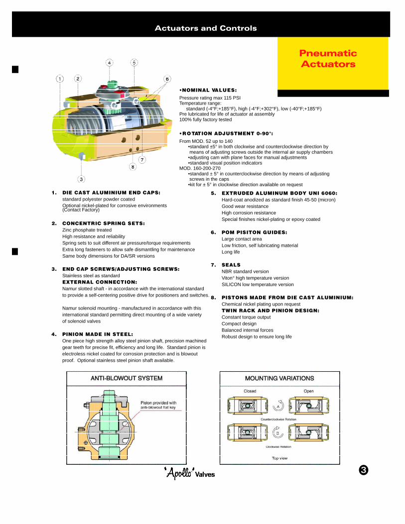
Models Fro m1 6 0 - 2 0 0 - 2 7 0
Actuators and Controls
ITEM DESCRIPTION MATERIAL TREATMENT1 Body Extruded aluminium Hard anodized 1 12 Anti-blowout pinion Steel Nickel plated 1 1
• 3 Lower pinion o-ring NBR 1 1• 4 Top pinion o-ring NBR 1 1• 5 Pinion bearing top POM 1 1
6 Pinion snap ring Steel Nickle plated 1 17 Piston Die cast aluminium 2 2
• 8 Piston o-ring NBR 2 2• 9 Bearing piston head PTFE 15% graphite 2 2•10 Bearing, piston back POM 4 6 4 6•11 Stop bolt o-ring NBR 2 212 Washer Stainless steel 2 213 Travel stop nut Stainless steel 2 214 Travel stop screw Stainless steel 2 215 External spring Steel Zinc-phosphate 016 Central spring Steel Zinc-phosphate 017 Internal spring Steel Zinc-phosphate 018 Left end cap Die cast aluminium Painted 1 119 Right end cap Die cast aluminium Painted 1 120 End cap screw Stainless steel 8 12 8 1221 End cap o-ring - large NBR 2 222 End cap o-ring - small NBR 2 223*** Precompressed spring Steel Zinc-phosphate 0
24*** Bearing PTFE 15% graphite 1 1• 25*** Pinion washer Stainless steel 1 1
UPON REQUEST CLOSED POSITION ADJUSTMENT26 Plate GGG40 Painted 1 127 Coupling Steel Nickel plated 1 1
• 28 Antifriction ring PTFE 1 129 Stop screw Steel Zinc plated 1 130 Stop bolt retaining nut Stainless steel 1 131 Fixing screws Stainless steel 4 4
QTY. QTY.DA SR
see springsetting atpage xx
see springsetting atpage xx
• Parts subject to wear 6,12, *** Valid for model 270 only
ONLY MODEL 270
UPON REQUEST CLOSED POSITION ADJUSTMENT
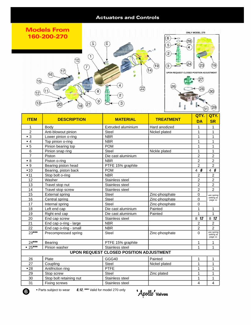
D i m e n s i o n sM o d e l s
3 2 - 1 6 0 - 2 0 0 - 2 7 0
8
Actuators and Controls
MOD. DRILLINGISO 5211 CH A B C D E F G H I L M N O P ØQ R S T U V W
32 F03 0.394 4.33 1.77 0.89 0.89 2.56 1.77 0.39 1.97 - 1.42
160 F10-F12 1.066 20.55 7.36 3.43 3.94 8.58 7.40 1.18 3.15 5.12 4.92
200 F14 1.417 22.64 8.58 4.29 4.29 10.59 9.41 1.42 3.15 5.12 5.51
270 F16 1.81 26.46 11.42 5.71 5.71 14.21 13.03 1.42 3.15 5.12 6.50
3/8-16 UNC2BX0.59
- 0.47 0.46 - 1/8” - - - -
4.02 1.26 1.38 3.21 1/4” 6.30 1.77 2.20 2.50
- 1.54 1.97 3.46 1/4” 7.48 2.03 2.52 3.11
- 2.05 1.97 4.76 1/4” 9.06 2.68 3.11 4.37
10-24 UNC2BX0.29”
1/4”-20 UNC2BX0.71”
5/8”-11 UNC2BX0.98”
3/4”-10 UNC2BX1.18”
NPT
-
-
-
Optional Closed Postition Adjustment
Double ActingA c t u a t o r
Actuators and Controls
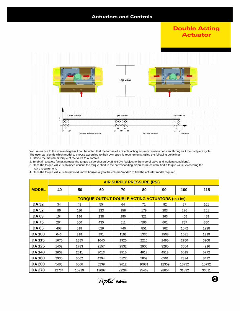
With reference to the above diagram it can be noted that the torque of a double acting actuator remains constant throughout the complete cycle.The user can decide which model to choose according to their own specific requirements, using the following guidelines:1. Define the maximum torque of the valve to automate.2. To obtain a safety factor,increase the torque value chosen by 25%-50% (subject to the type of valve and working conditions).3. Once the torque value is obtained consult the torque chart in the corresponding air pressure column, find a torque value exceeding the
valve requirement.4. Once the torque value is determined, move horizontally to the column “model” to find the actuator model required.
DA 32 34 43 55 64 71 82 87 101
DA 52 86 110 133 156 179 203 226 261
DA 63 154 196 238 280 321 363 405 468DA 75 284 360 435 511 586 661 737 850
DA 85 408 518 629 740 851 962 1072 1238
DA 100 646 818 991 1163 1336 1508 1681 1939
DA 115 1070 1355 1640 1925 2210 2495 2780 3208
DA 125 1409 1783 2157 2532 2906 3280 3654 4216
DA 140 2009 2511 3013 3515 4018 4513 5015 5772DA 160 2930 3662 4394 5127 5859 6591 7324 8422
DA 200 5488 6866 8239 9612 10981 12359 13732 15792
DA 270 12734 15919 19097 22284 25469 28654 31832 36611
AIR SUPPLY PRESSURE (PSI)
TORQUE OUTPUT DOUBLE ACTING ACTUATORS (In-Lbs)
MODEL 40 50 60 70 80 90 100 115
9
PRETENSIONED SPRING
Spring ReturnA c t u a t o r
10
Actuators and Controls
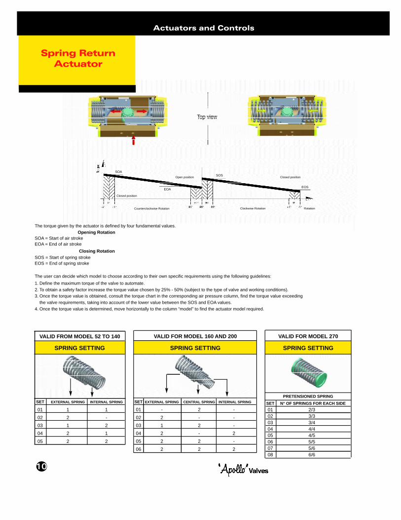
The torque given by the actuator is defined by four fundamental values.Opening Rotation
SOA = Start of air strokeEOA = End of air stroke
Closing RotationSOS = Start of spring strokeEOS = End of spring stroke
The user can decide which model to choose according to their own specific requirements using the following guidelines:1. Define the maximum torque of the valve to automate.2. To obtain a safety factor increase the torque value chosen by 25% - 50% (subject to the type of valve and working conditions).3. Once the torque value is obtained, consult the torque chart in the corresponding air pressure column, find the torque value exceeding
the valve requirements, taking into account of the lower value between the SOS and EOA values.4. Once the torque value is determined, move horizontally to the column “model” to find the actuator model required.
VALID FOR MODEL 160 AND 200 VALID FOR MODEL 270
SPRING SETTING
SET EXTERNAL SPRING INTERNAL SPRING
01 1 102 2 -03 1 204 2 105 2 2
VALID FROM MODEL 52 TO 140
SPRING SETTING
SET EXTERNAL SPRING CENTRAL SPRING INTERNAL SPRING
01 - 2 -02 2 - -03 1 2 -04 2 - 205 2 2 -06 2 2 2
SET N° OF SPRINGS FOR EACH SIDE01 2/302 3/303 3/404 4/405 4/506 5/507 5/608 6/6
SPRING SETTING
SOA
EOA
Closed position
Open position
Counterclockwise Rotation Clockwise Rotation
SOS Closed position
EOS
Rotation
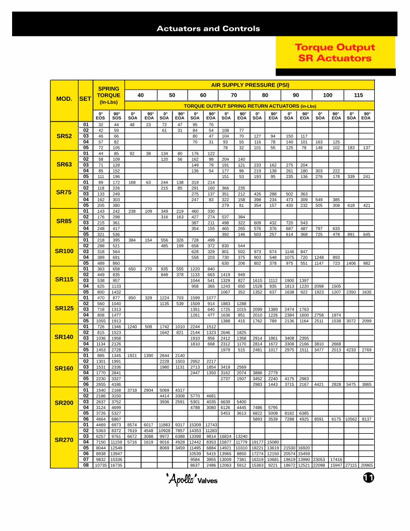
Torque OutputSR Actuators
11
Actuators and Controls
01 32 44 48 23 72 47 95 7002 42 59 61 31 84 54 108 7703 46 66 80 47 104 70 127 94 150 11704 57 82 70 31 93 55 116 78 140 101 163 12505 72 105 78 32 101 55 125 78 148 102 183 13701 44 85 92 38 134 80 176 12202 58 109 120 56 162 98 204 14003 71 128 149 79 191 121 233 162 275 20404 85 152 136 54 177 96 219 138 261 180 303 22205 111 196 151 53 193 95 235 136 276 178 339 24101 89 172 168 63 244 138 319 21402 118 226 215 85 291 160 366 23503 133 249 275 137 351 212 426 288 502 36304 162 303 247 83 322 158 398 234 473 309 549 38505 205 380 279 81 354 157 430 232 505 308 618 42101 143 242 238 109 349 219 460 33002 176 298 316 163 427 274 537 38403 215 361 387 211 498 322 609 432 720 54304 248 417 354 155 465 265 576 376 687 487 797 63305 321 536 392 146 503 257 614 368 725 478 891 64501 218 395 384 154 556 326 728 49902 288 521 485 199 658 372 830 54403 318 564 628 329 801 502 973 674 1146 84704 389 691 558 203 730 375 903 548 1075 720 1248 89305 489 860 630 206 802 378 975 551 1147 723 1406 98201 363 658 650 270 935 555 1220 84002 449 835 848 378 1133 663 1419 94903 538 957 1044 541 1329 827 1615 1112 1900 139704 625 1133 958 365 1243 650 1528 935 1813 1220 2098 150505 800 1432 1067 352 1352 637 1638 922 1923 1207 2350 163501 470 877 850 328 1224 703 1599 107702 560 1040 1135 539 1509 914 1883 128803 718 1313 1351 640 1725 1015 2099 1389 2474 176304 808 1477 1261 477 1636 851 2010 1226 2384 1600 2758 197405 1055 1913 1388 415 1762 789 2136 1164 2511 1538 3072 209901 726 1346 1240 508 1742 1010 2244 151202 815 1523 1642 821 2144 1323 2646 182503 1036 1958 1910 856 2412 1358 2914 1861 3408 235504 1134 2126 1810 668 2312 1170 2814 1672 3308 2166 3810 266805 1453 2728 1979 515 2481 1017 2975 1511 3477 2013 4233 276901 885 1345 1921 1390 2644 214002 1301 1991 2228 1503 2952 221703 1531 2336 1980 1131 2713 1854 3419 256904 1770 2841 2447 1350 3162 2074 3886 277905 2230 3327 2737 1507 3452 2240 4175 296306 2655 4186 2983 1443 3715 2167 4421 2828 5475 386501 1540 2168 3718 2904 5069 431702 2186 3150 4414 3308 5770 468103 2637 3752 3936 2591 5301 4035 6639 540004 3124 4699 4788 3080 6126 4445 7486 579505 3726 5327 5453 3613 6822 5008 8182 638506 4664 6867 5893 3539 7288 4925 8591 6175 10562 813701 4469 6973 8574 6017 11883 9317 15309 1274302 5363 8372 7619 4548 10928 7857 14353 1128303 6257 9761 6672 3088 9972 6388 13398 9814 16824 1324004 7150 11159 5716 1619 9016 4928 12442 8353 15877 11779 19177 1508005 8044 12549 8069 3459 11495 6884 14921 10310 18221 13619 21530 1692006 8938 13947 10539 5415 13965 8850 17274 12150 20574 1545907 9832 15336 9584 3955 13009 7381 16319 10681 19619 13990 23053 1741608 10735 16735 8637 2486 12063 5912 15363 9221 18672 12521 22098 15947 27115 20965
0° 90° 0° 90° 0° 90° 0° 90° 0° 90° 0° 90° 0° 90° 0° 90° 0° 90°EOS SOS SOA EOA SOA EOA SOA EOA SOA EOA SOA EOA SOA EOA SOA EOA SOA EOA
MOD. SETSPRINGTORQUE
(In-Lbs)
AIR SUPPLY PRESSURE (PSI)
TORQUE OUTPUT SPRING RETURN ACTUATORS (in-Lbs)
40 50 60 70 80 90 100 115
SR52
SR63
SR75
SR85
SR100
SR115
SR125
SR140
SR160
SR200
SR270
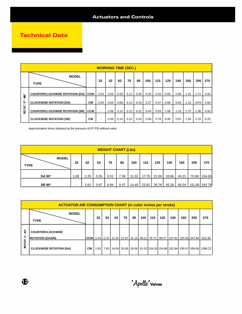
DA 90° 1.08 2.25 3.26 5.51 7.39 11.02 17.75 22.09 33.86 43.21 70.99 154.00
SR 90° - 2.62 3.97 6.94 9.37 14.40 23.92 26.76 45.28 65.04 111.00 192.79
Technical Data
12
Actuators and Controls
WORKING TIME (SEC.)
COUNTERCLOCKWISE ROTATION (DA) CCW 0.03 0.03 0.06 0.12 0.20 0.30 0.53 0.83 0.98 1.15 1.74 4.50
CLOCKWISE ROTATION (DA) CW 0.03 0.04 0.08 0.12 0.19 0.27 0.47 0.66 0.93 1.10 1070 4.50
COUNTERCLOCKWISE ROTATION (SR) CCW - 0.09 0.14 0.22 0.31 0.44 0.83 1.08 1.23 1.75 2.38 4.50
CLOCKWISE ROTATION (SR) CW - 0.09 0.14 0.22 0.33 0.46 0.78 0.90 0.97 1.34 2.19 6.20
MODEL
TYPE32 52 63 75 85 100 115 125 140 160 200 270
WEIGHT CHART (Lbs)
MODEL
TYPE32 52 63 75 85 100 115 125 140 160 200 270
ACTUATOR AIR CONSUMPTION CHART (in cubic inches per stroke)
COUNTERCLOCKWISE
ROTATION (DA/SR) CCW 2.44 6.10 11.50 21.97 31.12 48.21 78.72 99.47 137.91 220.30 347.84 915.36
CLOCKWISE ROTATION (DA) CW 1.83 7.93 14.04 26.85 39.06 61.02 104.35 134.86 192.84 290.47 599.86 1086.22
MODEL
TYPE32 52 63 75 85 100 115 125 140 160 200 270
Approximative times obtained at the pressure of 87 PSI without valve