Embed Size (px)
Citation preview
ME 270 – Fall 2019 Final exam review material
TOPIC Fall14 Fall15 Fall16 Fall17 Spring14 Spring15 Spring16 Spring17 Spring181 vectoroperations2 equilibriumofparticles 1a 1a 1b 1a 1a3 equilibriumofrigidbodies 3,5a 2,5a 2,4a 1b,5a 1a,2 1a,2,4a 1b,2,5a 1b,2,5a 5a4 equivalentsystems 2c 3a 5a5 centroids 1c 4d 3a6 hydrostaticloads 2a 1d 3d 1c7 friction 2b 1c 3c 2 1d,3 1d 1c 1c 2a,2b8 trusses 4 1b 1c 1b 1d,3a,3b 3 1a9 framesandmachines 3 1 1d 1c 3 3c 1d 1b10 SF/BMdiagrams 5b 4a,5b 4b 5b 5b 4b 4a,5b 4a,5b 3b,5b
axialstress 1f 3c 3e 3eshearstress-directshear 1d 1h 3d 4c 5a 3c 1cshearstress-torsion 1b 4b 3e 4 4d 5b 4b 4b 3c,4flexuralstress-bending 5c,5d 5c,5d,5f 4c,4e 5e 5d 4c,4d,4e 5c,5d 5c,5d 3d,5c
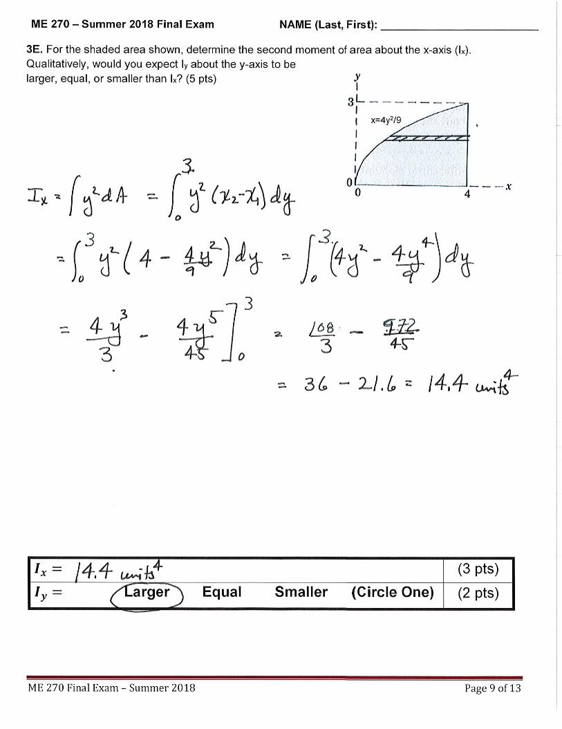
12 2ndareamoments 4c,4d 3b,4e 3a,3b,5d 4b,5c 5c,5d 4c,4d 4c,4d 1d,3aOther 1a 4a
ME270:TopicsofQuestionsfromPastFinalExams
11

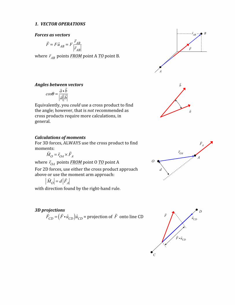
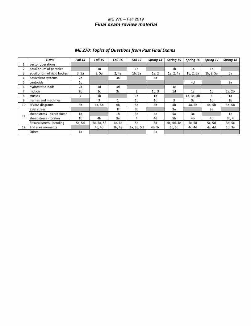
1.VECTOROPERATIONSForcesasvectors
!F = FuAB = F
!rAB!rAB
where !rAB pointsFROMpointATOpointB.
Anglesbetweenvectors
cosθ =
!a i!b!a!b
Equivalently,youcoulduseacrossproducttofindtheangle;however,thatisnotrecommendedascrossproductsrequiremorecalculations,ingeneral.CalculationsofmomentsFor3Dforces,ALWAYSusethecrossproducttofindmoments:
!MO = !rOA ×
!FA
where !rOA pointsFROMpointOTOpointA
For2Dforces,useeitherthecrossproductapproachaboveorusethemomentarmapproach:
!
MO = d!FA
withdirectionfoundbytheright-handrule.3Dprojections
!FCD =
!F i uCD( )uCD =projectionof
!F ontolineCD
A
B
!F
!rAB
!a
!b
A
!FA
!rOA
O
d
D !F
C
!F i uCD
uCD
A
B
!F
!rAB
!a
!b
A
!FA
!rOA
O
d
D !F
C
!F i uCD
uCD
A
B
!F
!rAB
!a
!b
A
!FA
!rOA
O
d
D !F
C
!F i uCD
uCD
A
B
!F
!rAB
!a
!b
A
!FA
!rOA
O
d
D !F
C
!F i uCD
uCD
equivalent
SystemI SystemII
y
x
y
x
w( x ) F d
Bequivalent
SystemI SystemII
B
F
M
A A
L L
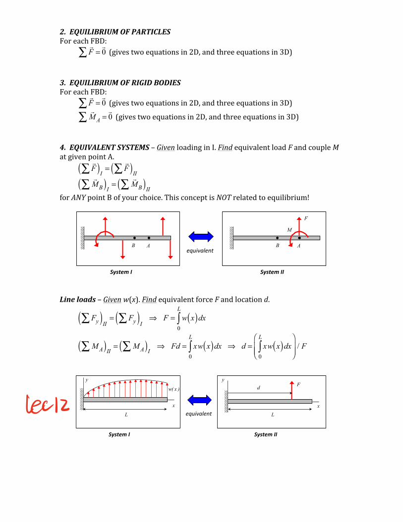
2.EQUILIBRIUMOFPARTICLESForeachFBD:
!F∑ =!0 (givestwoequationsin2D,andthreeequationsin3D)
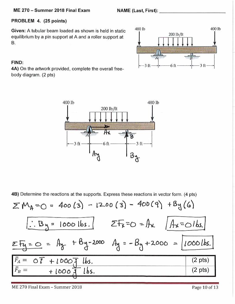
3.EQUILIBRIUMOFRIGIDBODIESForeachFBD:
!F∑ =!0 (givestwoequationsin2D,andthreeequationsin3D)
!
M A∑ =!0 (givestwoequationsin2D,andthreeequationsin3D)
4.EQUIVALENTSYSTEMS–GivenloadinginI.FindequivalentloadFandcoupleMatgivenpointA.
!F∑( )I
=!F∑( )II
!
M B∑( )I=
!M B∑( )II
forANYpointBofyourchoice.ThisconceptisNOTrelatedtoequilibrium!Lineloads–Givenw(x).FindequivalentforceFandlocationd.
Fy∑( )II= Fy∑( )I
⇒ F = w x( )dx0
L
∫
M A∑( )II= M A∑( )I
⇒ Fd = xw x( )dx0
L
∫ ⇒ d = xw x( )dx0
L
∫⎛
⎝⎜⎜
⎞
⎠⎟⎟
/ F
equivalent
SystemI SystemII
y
x
y
x
w( x ) F d
Bequivalent
SystemI SystemII
B
F
M
A A
Lech
a
b
x
y
x2 y( )
x1 y( )
dy
12
x2 + x1( )
y
a
b
x
y
y2 x( )
y1 x( )
dx
12
y1 + y2( )
x
a
b
x
y
x2 y( )
x1 y( )
dy
12
x2 + x1( )
y
a
b
x
y
y2 x( )
y1 x( )
dx
12
y1 + y2( )
x
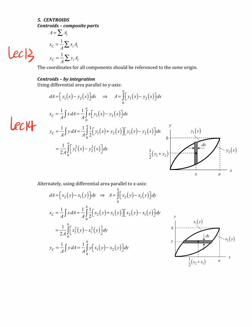
5.CENTROIDSCentroids–compositeparts A = Ai∑
xC = 1
Axi Ai∑
yC = 1
Ayi Ai∑
Thecoordinatesforallcomponentsshouldbereferencedtothesameorigin.Centroids–byintegrationUsingdifferentialareaparalleltoy-axis:
dA = y1 x( )− y2 x( )⎡⎣ ⎤⎦dx ⇒ A = y1 x( )− y2 x( )⎡⎣ ⎤⎦dx
0
a
∫
xC = 1
Ax dA∫ = 1
Ax y1 x( )− y2 x( )⎡⎣ ⎤⎦dx
0
a
∫
yC = 1A
y dA∫ = 1A
12
y1 x( ) + y2 x( )⎡⎣ ⎤⎦ y1 x( )− y2 x( )⎡⎣ ⎤⎦dx0
a
∫
= 12A
y12 x( )− y2
2 x( )⎡⎣
⎤⎦dx
0
a
∫
Alternately,usingdifferentialareaparalleltox-axis:
dA = x2 y( )− x1 y( )⎡⎣ ⎤⎦dy ⇒ A = x2 y( )− x1 y( )⎡⎣ ⎤⎦dy
0
b
∫
xC = 1A
x dA∫ = 1A
12
x2 y( ) + x1 y( )⎡⎣ ⎤⎦ x2 y( )− x1 y( )⎡⎣ ⎤⎦dy0
b
∫
= 12A
x22 y( )− x1
2 y( )⎡⎣
⎤⎦dy
0
b
∫
yC = 1
Ay dA∫ = 1
Ay x1 y( )− x2 y( )⎡⎣ ⎤⎦dy
0
b
∫
LeoB
lect
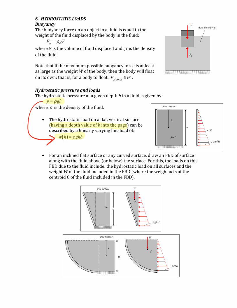
6.HYDROSTATICLOADSBuoyancyThebuoyancyforceonanobjectinafluidisequaltotheweightofthefluiddisplacedbythebodyinthefluid: FB = ρgV whereVisthevolumeoffluiddisplacedand ρ isthedensityofthefluid.NotethatifthemaximumpossiblebuoyancyforceisatleastaslargeastheweightWofthebody,thenthebodywillfloatonitsown;thatis,forabodytofloat: FB,max ≥W .HydrostaticpressureandloadsThehydrostaticpressureatagivendepthhinafluidisgivenby: p = ρgh where ρ isthedensityofthefluid.
• Thehydrostaticloadonaflat,verticalsurface(havingadepthvalueofbintothepage)canbedescribedbyalinearlyvaryinglineloadof:
w h( ) = ρghb
• Foraninclinedflatsurfaceoranycurvedsurface,drawanFBDofsurfacealongwiththefluidabove(orbelow)thesurface.Forthis,theloadsonthisFBDduetothefluidinclude:thehydrostaticloadonallsurfacesandtheweightWofthefluidincludedintheFBD(wheretheweightactsatthecentroidCofthefluidincludedintheFBD).
W
FB
fluidofdensityρ
free surface
ρgbH
W
C
H
h
free surface
h
ρgbH
W
C
H
Hw(h)
free surface
h
fluid
ρgbHG
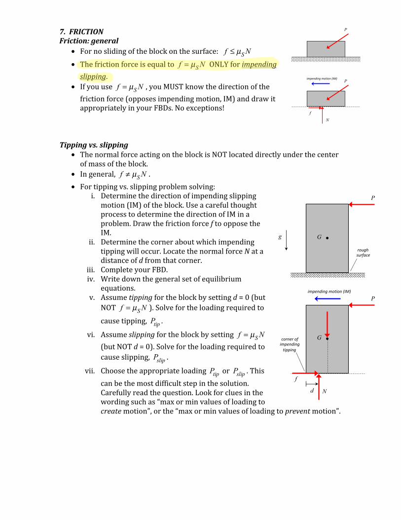
7.FRICTIONFriction:general
• Fornoslidingoftheblockonthesurface: f ≤ µS N • Thefrictionforceisequalto f = µS N ONLYforimpendingslipping.
• Ifyouuse f = µS N ,youMUSTknowthedirectionofthefrictionforce(opposesimpendingmotion,IM)anddrawitappropriatelyinyourFBDs.Noexceptions!
Tippingvs.slipping
• ThenormalforceactingontheblockisNOTlocateddirectlyunderthecenterofmassoftheblock.
• Ingeneral, f ≠ µS N .• Fortippingvs.slippingproblemsolving:
i. Determinethedirectionofimpendingslippingmotion(IM)oftheblock.UseacarefulthoughtprocesstodeterminethedirectionofIMinaproblem.DrawthefrictionforceftoopposetheIM.
ii. Determinethecorneraboutwhichimpendingtippingwilloccur.LocatethenormalforceNatadistanceofdfromthatcorner.
iii. CompleteyourFBD.iv. Writedownthegeneralsetofequilibrium
equations.v. Assumetippingfortheblockbysettingd=0(but
NOT f = µS N ).Solvefortheloadingrequiredtocausetipping, Ptip .
vi. Assumeslippingfortheblockbysetting f = µS N (butNOTd=0).Solvefortheloadingrequiredtocauseslipping, Pslip .
vii. Choosetheappropriateloading Ptip or Pslip .Thiscanbethemostdifficultstepinthesolution.Carefullyreadthequestion.Lookforcluesinthewordingsuchas“maxorminvaluesofloadingtocreatemotion”,orthe“maxorminvaluesofloadingtopreventmotion”.
g
P
G
roughsurface
P
Gcornerofimpendingtipping
f
N
impendingmotion(IM)
d
P
N f
Pimpendingmotion(IM)
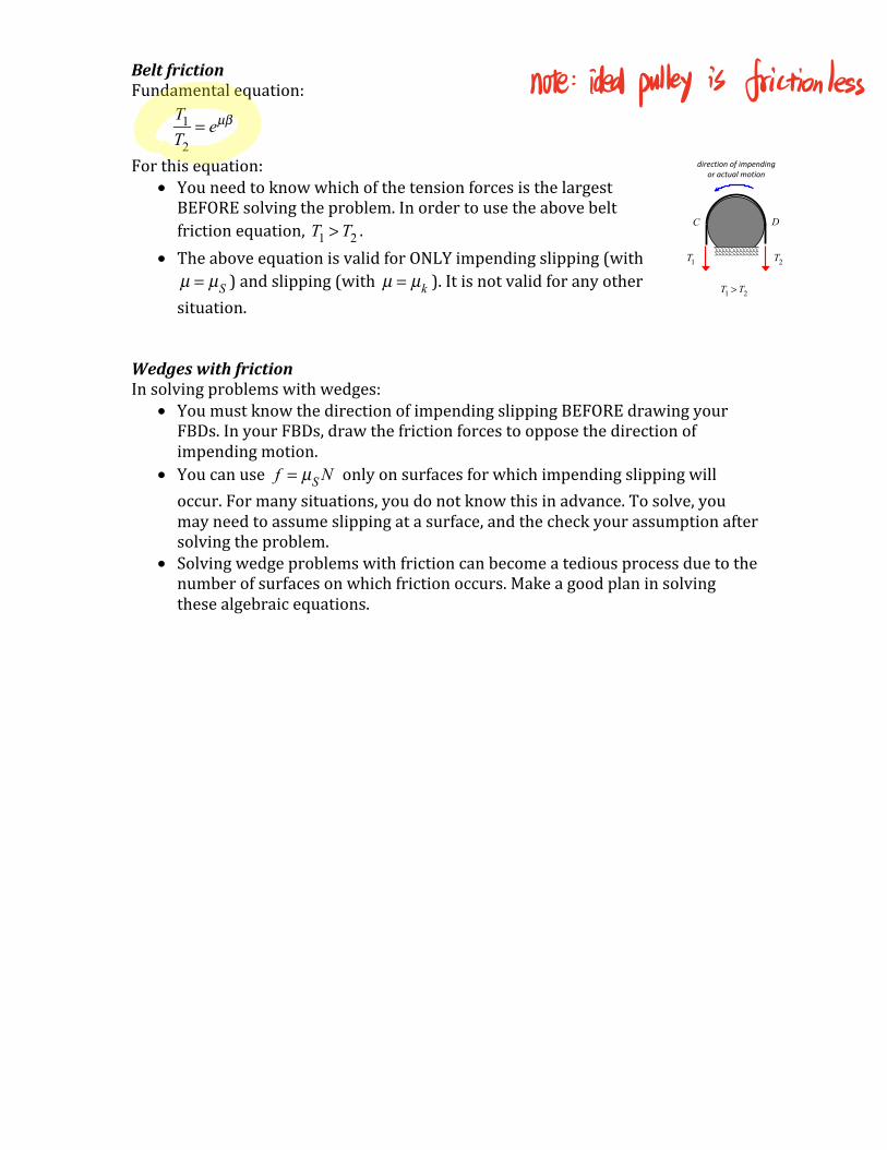
BeltfrictionFundamentalequation:
T1T2
= eµβ
Forthisequation:• YouneedtoknowwhichofthetensionforcesisthelargestBEFOREsolvingtheproblem.Inordertousetheabovebeltfrictionequation, T1 > T2 .
• TheaboveequationisvalidforONLYimpendingslipping(with µ = µS )andslipping(with µ = µk ).Itisnotvalidforanyothersituation.
WedgeswithfrictionInsolvingproblemswithwedges:
• YoumustknowthedirectionofimpendingslippingBEFOREdrawingyourFBDs.InyourFBDs,drawthefrictionforcestoopposethedirectionofimpendingmotion.
• Youcanuse f = µS N onlyonsurfacesforwhichimpendingslippingwilloccur.Formanysituations,youdonotknowthisinadvance.Tosolve,youmayneedtoassumeslippingatasurface,andthecheckyourassumptionaftersolvingtheproblem.
• Solvingwedgeproblemswithfrictioncanbecomeatediousprocessduetothenumberofsurfacesonwhichfrictionoccurs.Makeagoodplaninsolvingthesealgebraicequations.
directionofimpendingoractualmotion
C D
T1 T2
T1 > T2
note idealpulley is frictionless
8.TRUSSESItisgenerallyrecommendedthatyousolveforallreactionsonthetrussstructurebeforeattemptingtosolveforinternalloads.• Methodofjoints
Withthismethod:o DrawFBDsofindividualjointsinthetruss.o Itisrecommendedthatyoudrawallreactionsforcesonthejointsdueto
trussmembersusingthesameassumption(tensionorcompression).Forexample,ifyouchoosetodrawtheminTENSION,thenthememberforcespointOUTWARDfromthejoint.Ifyoufindanegativesolutionforanymemberforce,thenthatsaysthatyouroriginalassumptionwasincorrect.(Again,ifyouassumedamemberwasintension,findinganegativevaluefortheloadsaysthatthememberisincompression.)
o FromeachFBD,youcanwritedowntwoequilibriumequations.o Thismethodcanbecometedious,especiallyfortrusseswithalargenumber
ofjoints.
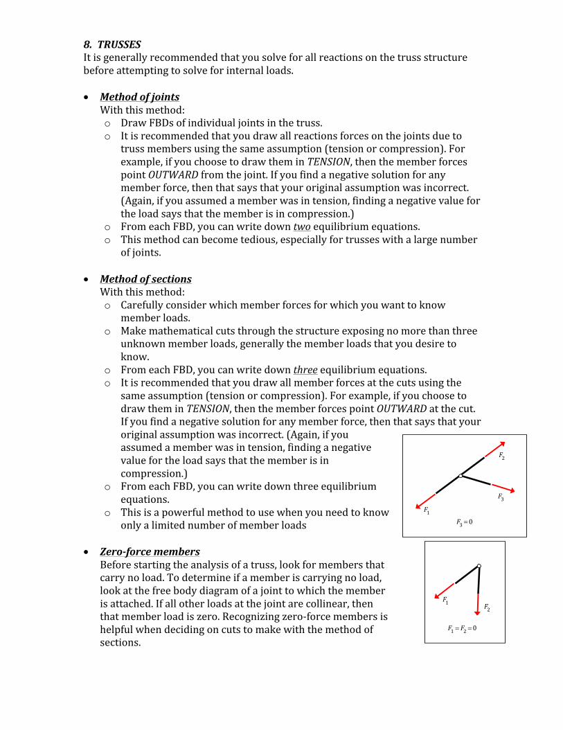
• MethodofsectionsWiththismethod:o Carefullyconsiderwhichmemberforcesforwhichyouwanttoknow
memberloads.o Makemathematicalcutsthroughthestructureexposingnomorethanthree
unknownmemberloads,generallythememberloadsthatyoudesiretoknow.
o FromeachFBD,youcanwritedownthreeequilibriumequations.o Itisrecommendedthatyoudrawallmemberforcesatthecutsusingthe
sameassumption(tensionorcompression).Forexample,ifyouchoosetodrawtheminTENSION,thenthememberforcespointOUTWARDatthecut.Ifyoufindanegativesolutionforanymemberforce,thenthatsaysthatyouroriginalassumptionwasincorrect.(Again,ifyouassumedamemberwasintension,findinganegativevaluefortheloadsaysthatthememberisincompression.)
o FromeachFBD,youcanwritedownthreeequilibriumequations.
o Thisisapowerfulmethodtousewhenyouneedtoknowonlyalimitednumberofmemberloads
• Zero-forcemembersBeforestartingtheanalysisofatruss,lookformembersthatcarrynoload.Todetermineifamemberiscarryingnoload,lookatthefreebodydiagramofajointtowhichthememberisattached.Ifallotherloadsatthejointarecollinear,thenthatmemberloadiszero.Recognizingzero-forcemembersishelpfulwhendecidingoncutstomakewiththemethodofsections.
F1
F2
F3
F3 =0
F1F2
F1 = F2 =0
9.FRAMESANDMACHINES• Generallystartouttheanalysisofframesandmachinesbyfirstdetermining
theexternalreactions.• Next,drawafreebodydiagramofeachmemberintheframe/machine.• NotethatmostmembersinframesandmachinesareNOTtwo-force
members.Asaresult,theloadingsatjointsduetoanontwo-forcememberareNOTalignedwiththemember;forthese,drawthereactionsashavingbothx-andy-components,withpossiblycouples.
• Makeaplanforyoursolution.Avoidsolvingforinternalreactionsthatyoudonotneed.Chooseyourmomentequationsaboutpointsthatallowyoutosolveoneequationforoneunknown,wheneverpossible.
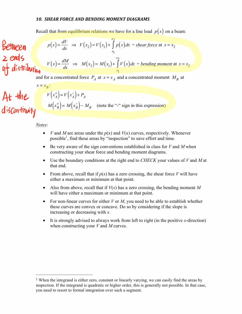
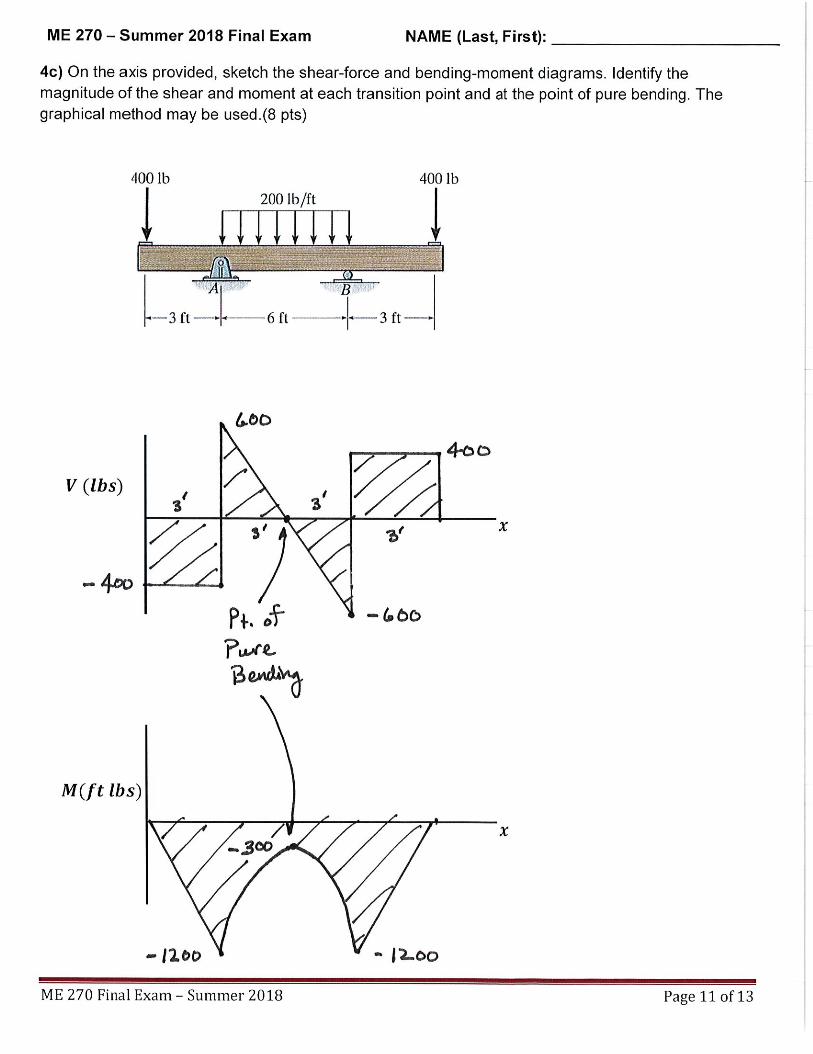
10.SHEARFORCEANDBENDINGMOMENTDIAGRAMSRecall that from equilibrium relations we have for a line load p x( ) on a beam:
p x( ) = dVdx
⇒ V x2( ) =V x1( ) + p x( )dxx1
x2
∫ = shear force at x = x2
V x( ) = dMdx
⇒ M x2( ) = M x1( ) + V x( )dxx1
x2
∫ = bending moment at x = x2
and for a concentrated force PA at x = xA and a concentrated moment M B at
x = xB :
V xA
+( ) =V xA−( ) + PA
M xB
+( ) = M xB−( )− M B (note the “-“ sign in this expression)
Notes:
• V and M are areas under the p(x) and V(x) curves, respectively. Whenever possible1, find these areas by “inspection” to save effort and time.
• Be very aware of the sign conventions established in class for V and M when constructing your shear force and bending moment diagrams.
• Use the boundary conditions at the right end to CHECK your values of V and M at that end.
• From above, recall that if p(x) has a zero crossing, the shear force V will have either a maximum or minimum at that point.
• Also from above, recall that if V(x) has a zero crossing, the bending moment M will have either a maximum or minimum at that point.
• For non-linear curves for either V or M, you need to be able to establish whether these curves are convex or concave. Do so by considering if the slope is increasing or decreasing with x.
• It is strongly advised to always work from left to right (in the positive x-direction) when constructing your V and M curves.
1When the integrand is either zero, constant or linearly varying, we can easily find the areas by inspection. If the integrand is quadratic or higher order, this is generally not possible. In that case, you need to resort to formal integration over such a segment.
Between
2ends
f distribution
At theiscontinuity
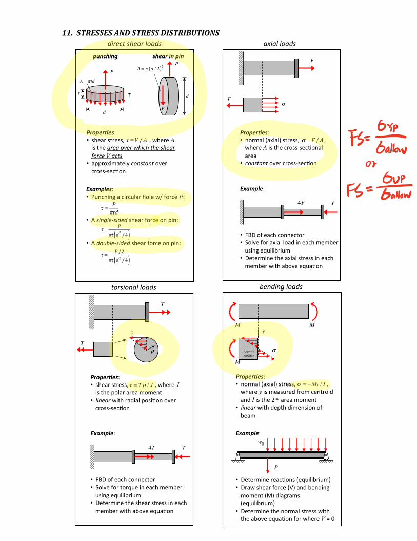
11.STRESSESANDSTRESSDISTRIBUTIONS
Stressesduetodirectshear,axial,torsionalandbendingloads
Proper6es:• shearstress,,whereAistheareaoverwhichtheshearforceVacts
• approximatelyconstantovercross-sec5on
τ =V /A
directshearloads
P
τt
d
A = πtd
P
V
d
A = π d / 2( )2punching shearinpin
Examples:• Punchingacircularholew/forceP:
• Asingle-sidedshearforceonpin:
• Adouble-sidedshearforceonpin:
τ = P
πtd
τ = P
πt d2 /4( )
τ = P /2
πt d2 /4( )
Stressesinstructuralmembersduetoaxial,torsionalandbendingloads
Proper6es:• normal(axial)stress,,whereAisthecross-sec5onalarea• constantovercross-sec5on
σ = F /A
Example:• FBDofeachconnector• Solveforaxialloadineachmemberusingequilibrium• Determinetheaxialstressineachmemberwithaboveequa5on
4F F
F
σF
axialloads
Proper6es:• shearstress,,whereJisthepolarareamoment
• linearwithradialposi5onovercross-sec5on
τ = Tρ / J
Example:• FBDofeachconnector• Solvefortorqueineachmemberusingequilibrium
• Determinetheshearstressineachmemberwithaboveequa5on
4T T
T
T
τ
ρ
Stressesinstructuralmembersduetoaxial,torsionalandbendingloads
torsionalloads
me270-cmk
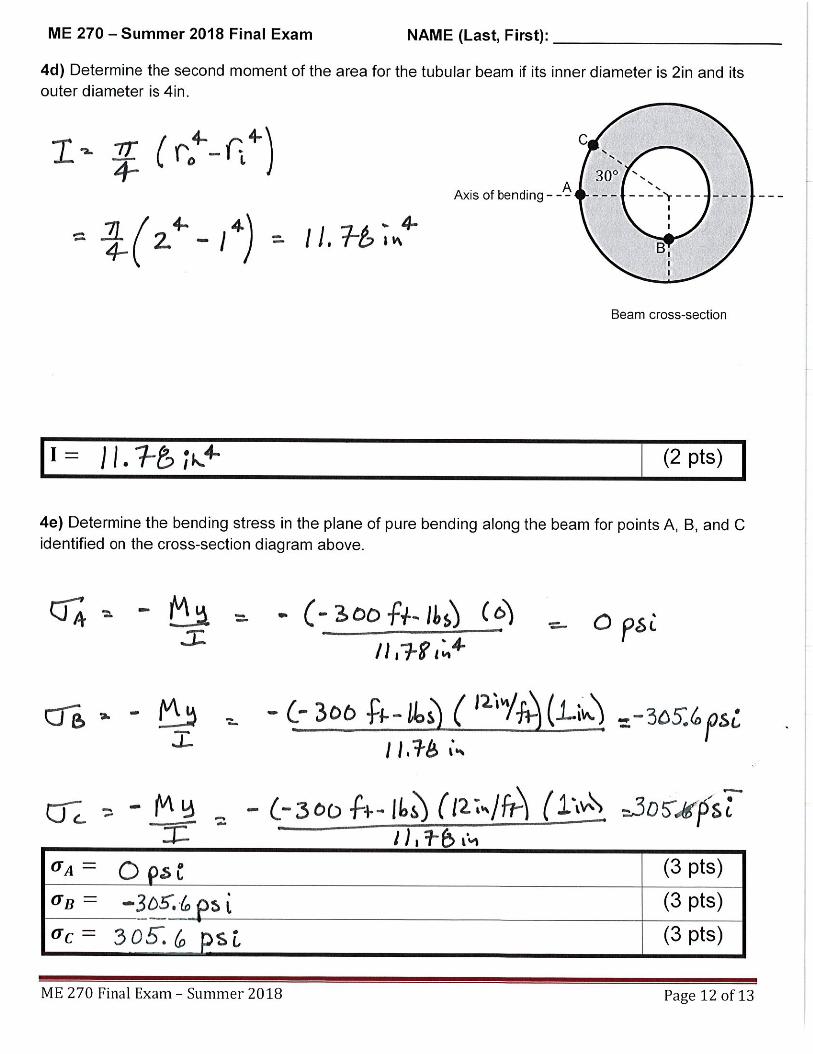
Proper6es:• normal(axial)stress,,whereyismeasuredfromcentroidandIisthe2ndareamoment• linearwithdepthdimensionofbeam
σ = −My / I
M
σ
M
M
y
neutral
Example:• Determinereac5ons(equilibrium)• Drawshearforce(V)andbendingmoment(M)diagrams(equilibrium)
• Determinethenormalstresswiththeaboveequa5onforwhereV=0
P
w0
bendingloads
surface
Fs OYLGallow02
FS Gallow
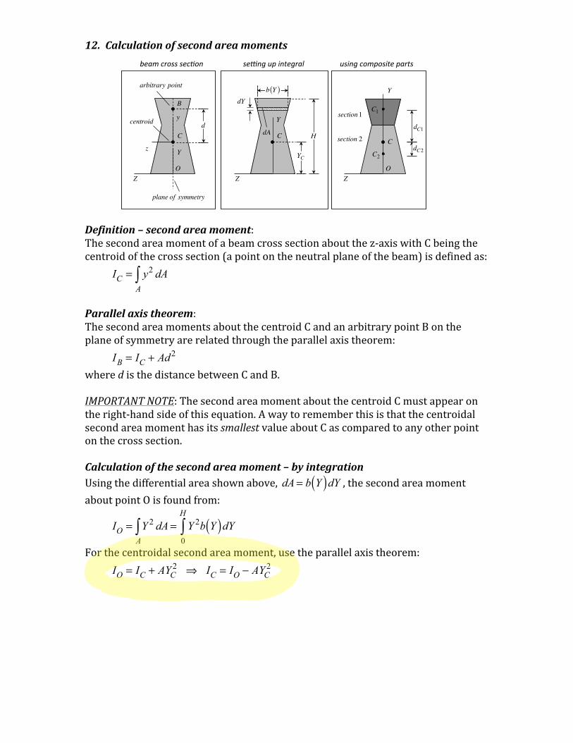
12.Calculationofsecondareamoments
Definition–secondareamoment:Thesecondareamomentofabeamcrosssectionaboutthez-axiswithCbeingthecentroidofthecrosssection(apointontheneutralplaneofthebeam)isdefinedas:
IC = y2 dA
A∫
Parallelaxistheorem:ThesecondareamomentsaboutthecentroidCandanarbitrarypointBontheplaneofsymmetryarerelatedthroughtheparallelaxistheorem: IB = IC + Ad2 wheredisthedistancebetweenCandB.IMPORTANTNOTE:ThesecondareamomentaboutthecentroidCmustappearontheright-handsideofthisequation.AwaytorememberthisisthatthecentroidalsecondareamomenthasitssmallestvalueaboutCascomparedtoanyotherpointonthecrosssection.Calculationofthesecondareamoment–byintegrationUsingthedifferentialareashownabove, dA = b Y( )dY ,thesecondareamomentaboutpointOisfoundfrom:
IO = Y 2 dA
A∫ = Y 2b Y( )dY
0
H
∫
Forthecentroidalsecondareamoment,usetheparallelaxistheorem: IO = IC + AYC
2 ⇒ IC = IO − AYC2
C
se#ngupintegral
dYb Y( )
dA
YC
Z
Y
Hd
C
B
Yz
Z
centroid
arbitrary point
plane of symmetry
y
beamcrosssec2on
O
C
usingcompositeparts
C2
C1section1
section 2
ZO
Y
dC2
dC1
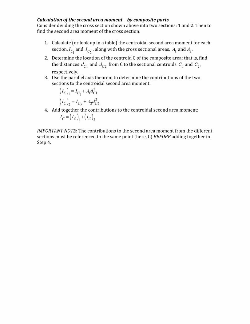
Calculationofthesecondareamoment–bycompositepartsConsiderdividingthecrosssectionshownaboveintotwosections:1and2.Thentofindthesecondareamomentofthecrosssection:
1. Calculate(orlookupinatable)thecentroidalsecondareamomentforeachsection,
IC1
and IC2
,alongwiththecrosssectionalareas, A1 and A2 .2. DeterminethelocationofthecentroidCofthecompositearea;thatis,find
thedistances dC1 and dC2 fromCtothesectionalcentroids C1 and C2 ,respectively.
3. Usetheparallelaxistheoremtodeterminethecontributionsofthetwosectionstothecentroidalsecondareamoment:
IC( )1 = IC1+ A1dC1
2
IC( )2 = IC2+ A2dC2
2
4. Addtogetherthecontributionstothecentroidalsecondareamoment:
IC = IC( )1 + IC( )2
IMPORTANTNOTE:Thecontributionstothesecondareamomentfromthedifferentsectionsmustbereferencedtothesamepoint(here,C)BEFOREaddingtogetherinStep4.