Embed Size (px)
Citation preview
Technical Service ManualAlaris® Auto-ID Module, Model 8600
Supports: Guardrails® Suite MX
August 2007
Alaris® Products
READY
SCANCANCEL
Alaris® Auto-ID ModuleTechnical Service Manual
General Contact Information
Cardinal HealthAlaris® ProductsSan Diego, California
cardinalhealth.com/alaris
Customer Advocacy - North America(Clinical and technical feedback.)Phone: 800.854.7128, ext. 7812
E-mail: [email protected]
Technical Support - North America(Maintenance and service information support; troubleshooting.)Phone, United States: 858.458.6003; 800.854.7128, ext. 6003
Phone, Canada: 800.387.8309
Customer Care - North America(Product return, service assistance, and order placement.)
Phone, United States: 800.482.4822Phone, Canada: 800.387.8309
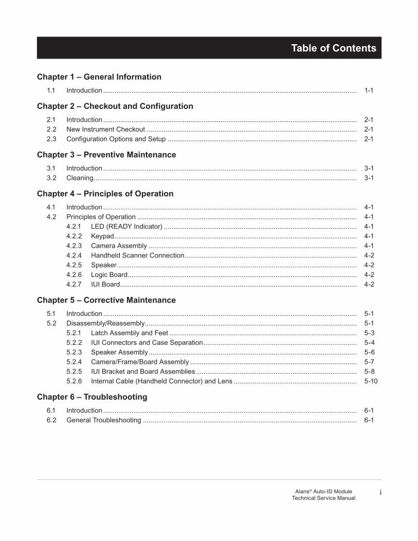
Table of Contents
iAlaris® Auto-ID ModuleTechnical Service Manual
Chapter 1 – General Information1.1 Introduction ...................................................................................................................................... 1-1
Chapter 2 – Checkout and Configuration2.1 Introduction ...................................................................................................................................... 2-12.2 New Instrument Checkout ............................................................................................................... 2-12.3 Configuration Options and Setup .................................................................................................... 2-1
Chapter 3 – Preventive Maintenance3.1 Introduction ...................................................................................................................................... 3-13.2 Cleaning ........................................................................................................................................... 3-1
Chapter 4 – Principles of Operation4.1 Introduction ...................................................................................................................................... 4-14.2 Principles of Operation .................................................................................................................... 4-1
4.2.1 LED (READy Indicator) ...................................................................................................... 4-14.2.2 Keypad ................................................................................................................................ 4-14.2.3 Camera Assembly .............................................................................................................. 4-14.2.4 Handheld Scanner Connection ........................................................................................... 4-24.2.5 Speaker ............................................................................................................................... 4-24.2.6 Logic Board ......................................................................................................................... 4-24.2.7 IUI Board ............................................................................................................................. 4-2
Chapter 5 – Corrective Maintenance5.1 Introduction ...................................................................................................................................... 5-15.2 Disassembly/Reassembly ................................................................................................................ 5-1
5.2.1 Latch Assembly and Feet ................................................................................................... 5-35.2.2 IUI Connectors and Case Separation ................................................................................. 5-45.2.3 Speaker Assembly .............................................................................................................. 5-65.2.4 Camera/Frame/Board Assembly ........................................................................................ 5-75.2.5 IUI Bracket and Board Assemblies ..................................................................................... 5-85.2.6 Internal Cable (Handheld Connector) and Lens ................................................................. 5-10
Chapter 6 – Troubleshooting6.1 Introduction ...................................................................................................................................... 6-16.2 General Troubleshooting ................................................................................................................. 6-1
ii
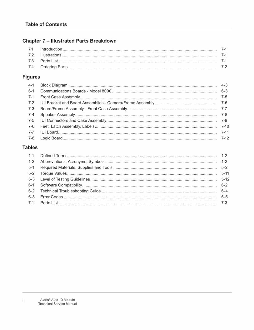
Table of Contents
Alaris® Auto-ID ModuleTechnical Service Manual
Chapter 7 – Illustrated Parts Breakdown7.1 Introduction ...................................................................................................................................... 7-17.2 Illustrations ....................................................................................................................................... 7-17.3 Parts List .......................................................................................................................................... 7-17.4 Ordering Parts ................................................................................................................................. 7-2
Figures4-1 Block Diagram ................................................................................................................................. 4-36-1 Communications Boards - Model 8000 ........................................................................................... 6-37-1 Front Case Assembly....................................................................................................................... 7-57-2 IUI Bracket and Board Assemblies - Camera/Frame Assembly ...................................................... 7-67-3 Board/Frame Assembly - Front Case Assembly .............................................................................. 7-77-4 Speaker Assembly ........................................................................................................................... 7-87-5 IUI Connectors and Case Assembly ................................................................................................ 7-97-6 Feet, Latch Assembly, Labels .......................................................................................................... 7-107-7 IUI Board .......................................................................................................................................... 7-117-8 Logic Board ...................................................................................................................................... 7-12
Tables1-1 Defined Terms ................................................................................................................................. 1-21-2 Abbreviations, Acronyms, Symbols ................................................................................................. 1-25-1 Required Materials, Supplies and Tools .......................................................................................... 5-25-2 Torque Values .................................................................................................................................. 5-115-3 Level of Testing Guidelines .............................................................................................................. 5-126-1 Software Compatibility ..................................................................................................................... 6-26-2 Technical Troubleshooting Guide .................................................................................................... 6-46-3 Error Codes ..................................................................................................................................... 6-57-1 Parts List .......................................................................................................................................... 7-3

1 G
EN
ER
AL IN
FO
RM
AT
ION
1-1Alaris® Auto-ID ModuleTechnical Service Manual
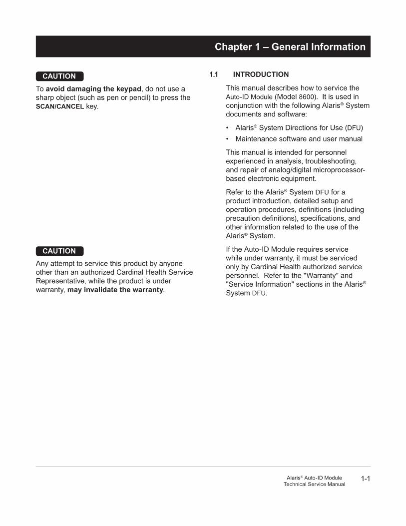
1.1 InTrOduCTIOn
This manual describes how to service the Auto-ID Module (Model 8600). It is used in conjunction with the following Alaris® System documents and software:
• Alaris® System Directions for Use (DFU)• Maintenance software and user manual
This manual is intended for personnel experienced in analysis, troubleshooting, and repair of analog/digital microprocessor- based electronic equipment.
Refer to the Alaris® System DFU for a product introduction, detailed setup and operation procedures, definitions (including precaution definitions), specifications, and other information related to the use of the Alaris® System.
If the Auto-ID Module requires service while under warranty, it must be serviced only by Cardinal Health authorized service personnel. Refer to the "Warranty" and "Service Information" sections in the Alaris® System DFU.
CauTIOnTo avoid damaging the keypad, do not use a sharp object (such as pen or pencil) to press the SCan/CanCel key.
CauTIOnAny attempt to service this product by anyone other than an authorized Cardinal Health Service Representative, while the product is under warranty, may invalidate the warranty.
Chapter 1 – General Information
1-2
General Information
Alaris® Auto-ID ModuleTechnical Service Manual
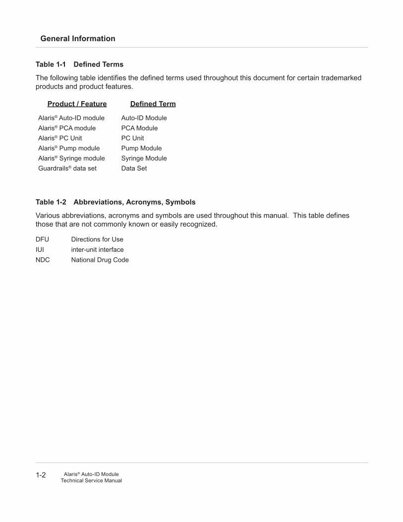
Table 1-1 Defined Terms
The following table identifies the defined terms used throughout this document for certain trademarked products and product features.
Product / Feature defined Term
Alaris® Auto-ID module Auto-ID ModuleAlaris® PCA module PCA ModuleAlaris® PC Unit PC UnitAlaris® Pump module Pump ModuleAlaris® Syringe module Syringe ModuleGuardrails® data set Data Set
Table 1-2 abbreviations, acronyms, Symbols
Various abbreviations, acronyms and symbols are used throughout this manual. This table defines those that are not commonly known or easily recognized.
DFU Directions for UseIUI inter-unit interfaceNDC National Drug Code

2 C
HE
CK
OU
T &
CO
NF
IGU
RA
TIO
N
2-1Alaris® Auto-ID ModuleTechnical Service Manual
CauTIOnShould an instrument be dropped or severely jarred, remove it from use immediately. It should be thoroughly tested and inspected by qualified service personnel to ensure proper function prior to reuse.
2.1 InTrOduCTIOn
This chapter describes Auto-ID Module initial setup and configuration.
2.2 new InSTruMenT CheCkOuT
Prior to placing a new instrument in use, perform a check-in procedure using the applicable maintenance software.
Contact Cardinal Health authorized service personnel if the instrument has physical damage or fails to satisfactorily pass the check-in test.
2.3 COnFIGuraTIOn OPTIOnS and SeTuP
Configure the Auto-ID Module using the applicable maintenance software.
Refer to the Alaris® System DFU for system configurable settings. Refer to the PC Unit/Pump Module Service Manual for instructions on how to change System Configuration parameters.
Chapter 2 – Checkout and Configuration

2-2
Checkout and Configuration
Alaris® Auto-ID ModuleTechnical Service Manual
THIS PAGEINTENTIONALLy
LEFT BLANK

3 P
RE
VE
NT
IVE
MA
INT
EN
AN
CE
3-1Alaris® Auto-ID ModuleTechnical Service Manual
warnInGFailure to perform regular and preventive maintenance inspections may result in improper instrument operation.
3.1 InTrOduCTIOn
Perform regular and preventive maintenance inspections to ensure that the Auto-ID Module remains in good operating condition.
• Perform regular inspections before each use.
• Perform preventive maintenance inspections once a year.
Use the applicable maintenance software to check in, upgrade/repair, diagnose, calibrate and perform preventive maintenance.
These requirements and guidelines are intended to complement the intent of the Joint Commission on Accreditation of Healthcare Organizations (JCAHO) requirements.
3.2 CleanInG
Refer to the Alaris® System DFU.
Chapter 3 – Preventive Maintenance

3-2
Preventive Maintenance
Alaris® Auto-ID ModuleTechnical Service Manual
THIS PAGEINTENTIONALLy
LEFT BLANK

4 P
RIN
CIP
LE
S O
F O
PE
RA
TIO
N
4-1Alaris® Auto-ID ModuleTechnical Service Manual
4.1 InTrOduCTIOn
This chapter describes the principles of operation for the Auto-ID Module.
Refer to the PC Unit/Pump Module Technical Service Manual for Alaris® System principles of operation.
4.2 PrInCIPleS OF OPeraTIOn
Circuit boards are not field repairable and must be returned to a Cardinal Health Service Center for repair.
4.2.1 led (ready Indicator)
A green LED on the front panel lights to confirm that the camera assembly (embedded scanner) or handheld scanner is ready to scan.
4.2.2 keypad
The keypad includes the SCan/CanCel key. Pressing once begins scanning, and pressing during scanning cancels the scan.
4.2.3 Camera assembly
The Camera Assembly reads bar codes (including linear and two-dimensional bar code formats) using technology similar to digital cameras. Bar code readers use high-intensity LEDs to illuminate the bar code image, allowing the code to be scanned regardless of ambient light conditions.
The Camera Assembly scans the bar code, then sends signals to decoding circuitry on the Logic Board.
Chapter 4 – Principles of Operation
4-2
Principles of Operation
Alaris® Auto-ID ModuleTechnical Service Manual
4.2.4 handheld Scanner Connection
Cardinal Health offers a handheld scanner that can be connected to the front panel of the Auto-ID Module. The Auto-ID Module is designed for use only with handheld scanners supplied by Cardinal Health.
4.2.5 Speaker
The speaker provides audible confirmation of key presses and successful scans.
4.2.6 logic Board
The Logic Board interfaces all of the Auto-ID Module components. Decoding circuitry on the Logic Board recognizes the bar code symbology, analyzes the content of the scanned code, and converts the data to a traditional data format.
The Logic Board receives its power from the PC Unit via the IUI Board. The Logic Board converts power to internal supply voltages and monitors supply voltages during operation.
A watchdog timer circuit is designed to put the Auto-ID Module into a safe state if the Logic Board main processor fails.
4.2.7 IuI Board
The IUI Board contains IUI circuitry that allows it to communicate with the PC Unit.
4-3
Principles of Operation
Alaris® Auto-ID ModuleTechnical Service Manual
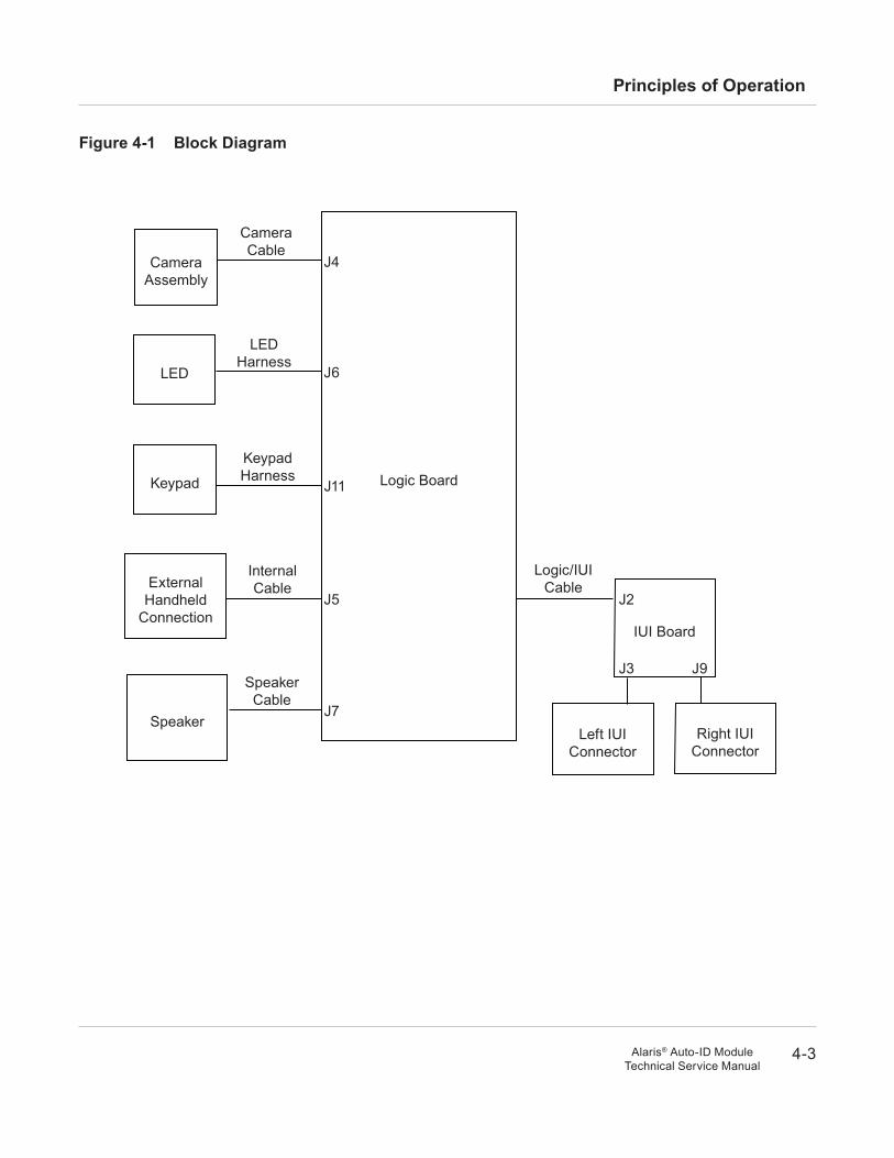
Figure 4-1 Block diagram
Camera Assembly
Logic Board
LED
Keypad
External Handheld
Connection
Speaker
IUI Board
J4
J6
J5
J11
J2
J7
Camera Cable
Keypad Harness
LED Harness
Internal Cable
Speaker Cable
Logic/IUI Cable
J3
Left IUI Connector
Right IUI Connector
J9

4-4
Principles of Operation
Alaris® Auto-ID ModuleTechnical Service Manual
THIS PAGEINTENTIONALLy
LEFT BLANK

5 C
OR
RE
CT
IVE
MA
INT
EN
AN
CE
5-1Alaris® Auto-ID ModuleTechnical Service Manual
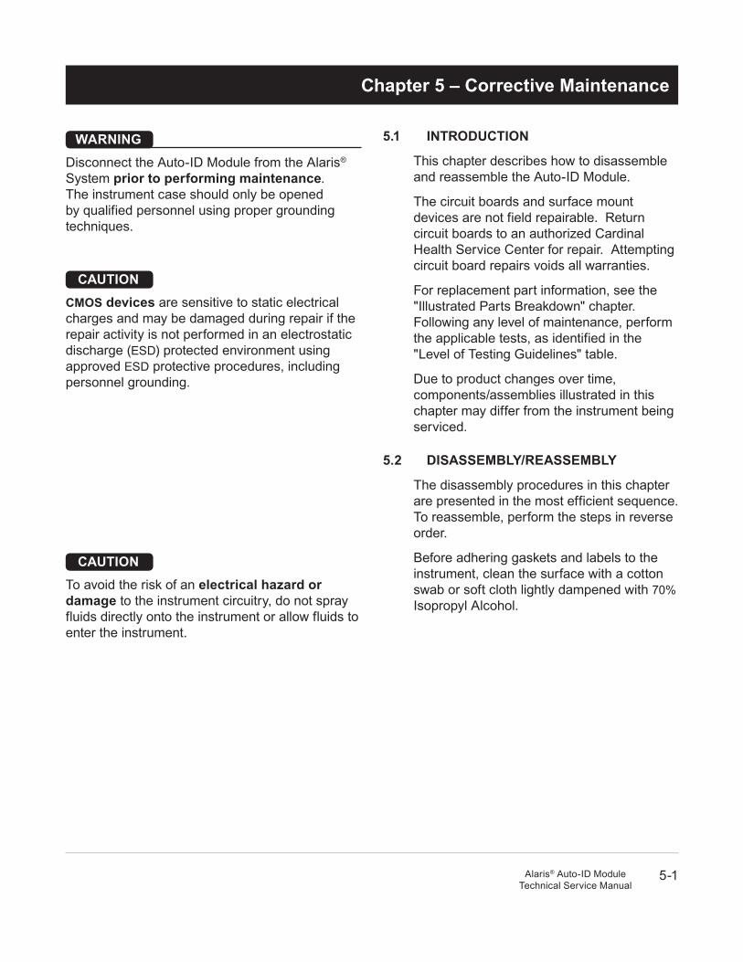
5.1 InTrOduCTIOn
This chapter describes how to disassemble and reassemble the Auto-ID Module.
The circuit boards and surface mount devices are not field repairable. Return circuit boards to an authorized Cardinal Health Service Center for repair. Attempting circuit board repairs voids all warranties.
For replacement part information, see the "Illustrated Parts Breakdown" chapter. Following any level of maintenance, perform the applicable tests, as identified in the "Level of Testing Guidelines" table.
Due to product changes over time, components/assemblies illustrated in this chapter may differ from the instrument being serviced.
5.2 dISaSSeMBly/reaSSeMBly
The disassembly procedures in this chapter are presented in the most efficient sequence. To reassemble, perform the steps in reverse order.
Before adhering gaskets and labels to the instrument, clean the surface with a cotton swab or soft cloth lightly dampened with 70% Isopropyl Alcohol.
warnInGDisconnect the Auto-ID Module from the Alaris® System prior to performing maintenance. The instrument case should only be opened by qualified personnel using proper grounding techniques.
CauTIOnCMOS devices are sensitive to static electrical charges and may be damaged during repair if the repair activity is not performed in an electrostatic discharge (ESD) protected environment using approved ESD protective procedures, including personnel grounding.
CauTIOnTo avoid the risk of an electrical hazard or damage to the instrument circuitry, do not spray fluids directly onto the instrument or allow fluids to enter the instrument.
Chapter 5 – Corrective Maintenance
5-2
Corrective Maintenance
Alaris® Auto-ID ModuleTechnical Service Manual
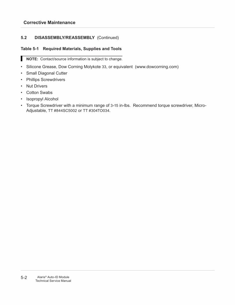
Table 5-1 required Materials, Supplies and Tools
nOTe: Contact/source information is subject to change.
• Silicone Grease, Dow Corning Molykote 33, or equivalent (www.dowcorning.com)• Small Diagonal Cutter• Phillips Screwdrivers• Nut Drivers• Cotton Swabs• Isopropyl Alcohol • Torque Screwdriver with a minimum range of 3-15 in-lbs. Recommend torque screwdriver, Micro-
Adjustable, TT #844SC5002 or TT #304TO034.
5.2 dISaSSeMBly/reaSSeMBly (Continued)
5-3
Corrective Maintenance
Alaris® Auto-ID ModuleTechnical Service Manual
5.2 dISaSSeMBly/reaSSeMBly (Continued)
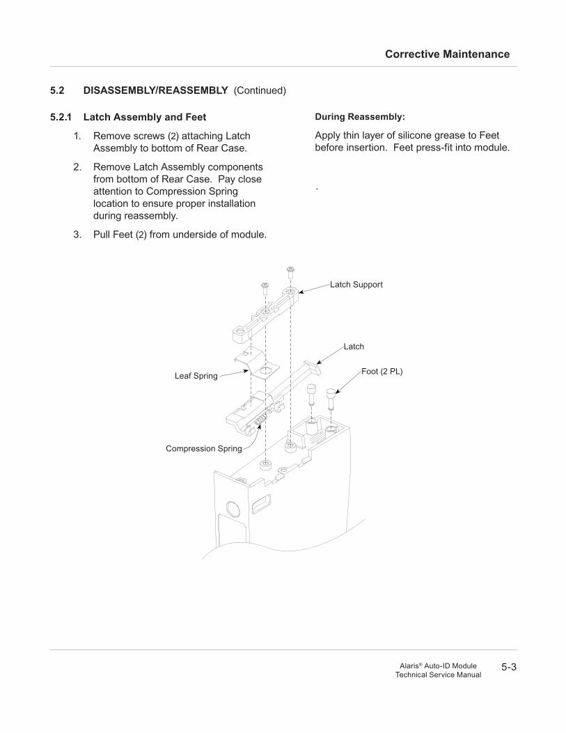
5.2.1 latch assembly and Feet
1. Remove screws (2) attaching Latch Assembly to bottom of Rear Case.
2. Remove Latch Assembly components from bottom of Rear Case. Pay close attention to Compression Spring location to ensure proper installation during reassembly.
3. Pull Feet (2) from underside of module.
during reassembly:
Apply thin layer of silicone grease to Feet before insertion. Feet press-fit into module.
Compression Spring
Foot (2 PL)
Latch
Latch Support
Leaf Spring
5-4
Corrective Maintenance
Alaris® Auto-ID ModuleTechnical Service Manual
5.2 dISaSSeMBly/reaSSeMBly (Continued)
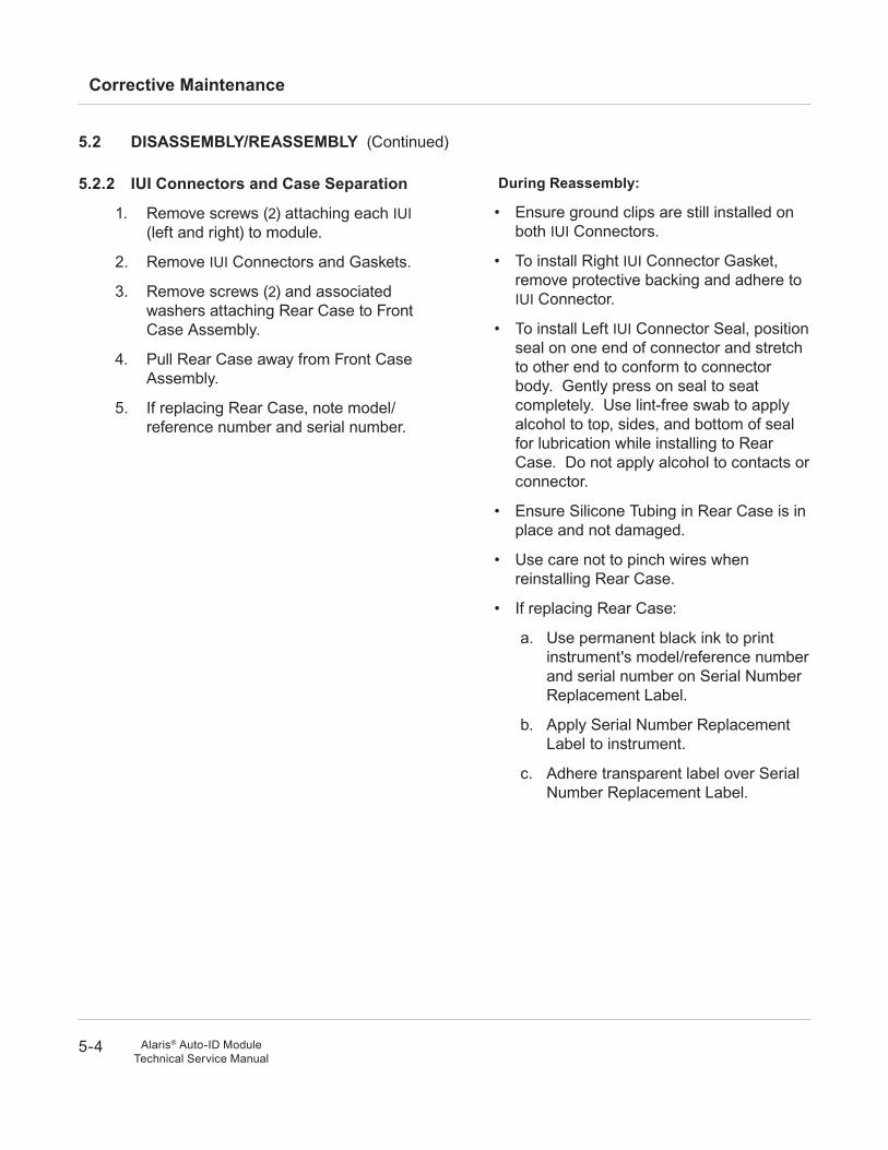
5.2.2 IuI Connectors and Case Separation
1. Remove screws (2) attaching each IUI (left and right) to module.
2. Remove IUI Connectors and Gaskets.
3. Remove screws (2) and associated washers attaching Rear Case to Front Case Assembly.
4. Pull Rear Case away from Front Case Assembly.
5. If replacing Rear Case, note model/reference number and serial number.
during reassembly:
• Ensure ground clips are still installed on both IUI Connectors.
• To install Right IUI Connector Gasket, remove protective backing and adhere to IUI Connector.
• To install Left IUI Connector Seal, position seal on one end of connector and stretch to other end to conform to connector body. Gently press on seal to seat completely. Use lint-free swab to apply alcohol to top, sides, and bottom of seal for lubrication while installing to Rear Case. Do not apply alcohol to contacts or connector.
• Ensure Silicone Tubing in Rear Case is in place and not damaged.
• Use care not to pinch wires when reinstalling Rear Case.
• If replacing Rear Case:
a. Use permanent black ink to print instrument's model/reference number and serial number on Serial Number Replacement Label.
b. Apply Serial Number Replacement Label to instrument.
c. Adhere transparent label over Serial Number Replacement Label.
5-5
Corrective Maintenance
Alaris® Auto-ID ModuleTechnical Service Manual
READY
SCANCANCEL
IUI Connector, Right
IUI Connector, Left
Silicone Tubing
Front Case assembly
5.2 dISaSSeMBly/reaSSeMBly (Continued)
5.2.2 IuI Connectors and Case Separation (Continued)
IUI Gasket
IUI Seal
5-6
Corrective Maintenance
Alaris® Auto-ID ModuleTechnical Service Manual
5.2 dISaSSeMBly/reaSSeMBly (Continued)
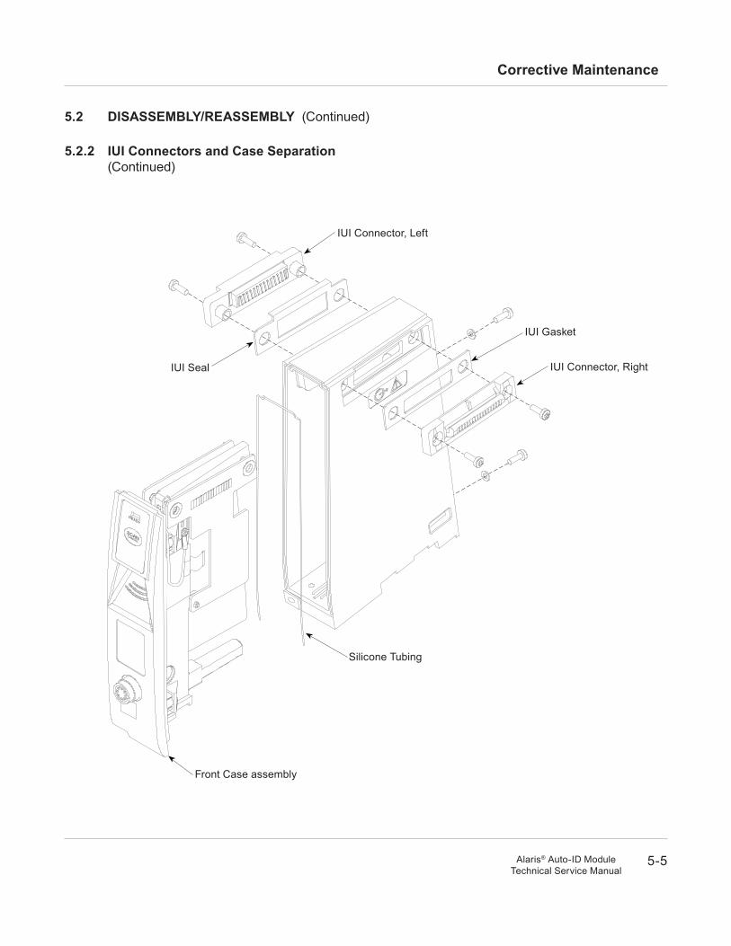
5.2.3 Speaker assembly
1. Disconnect Speaker Assembly cable from Logic Board J7.
2. Remove Speaker Assembly from Front Case.
during reassembly:
Speaker Assembly snaps into place when installed into Front Case.
J7
Logic Board
Speaker Assembly
5-7
Corrective Maintenance
Alaris® Auto-ID ModuleTechnical Service Manual
5.2 dISaSSeMBly/reaSSeMBly (Continued)
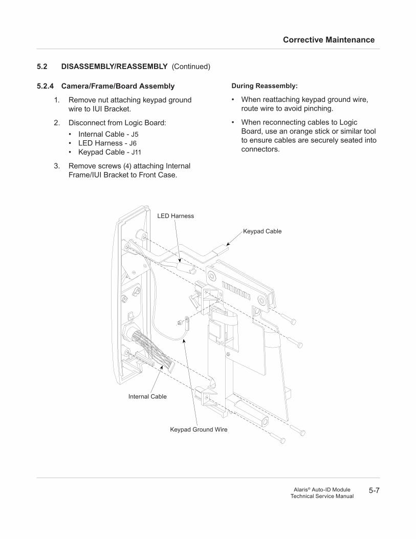
5.2.4 Camera/Frame/Board assembly
1. Remove nut attaching keypad ground wire to IUI Bracket.
2. Disconnect from Logic Board:• Internal Cable - J5• LED Harness - J6• Keypad Cable - J11
3. Remove screws (4) attaching Internal Frame/IUI Bracket to Front Case.
during reassembly:
• When reattaching keypad ground wire, route wire to avoid pinching.
• When reconnecting cables to Logic Board, use an orange stick or similar tool to ensure cables are securely seated into connectors.
Keypad Cable
Keypad Ground Wire
Internal Cable
LED Harness
5-8
Corrective Maintenance
Alaris® Auto-ID ModuleTechnical Service Manual
5.2 dISaSSeMBly/reaSSeMBly (Continued)
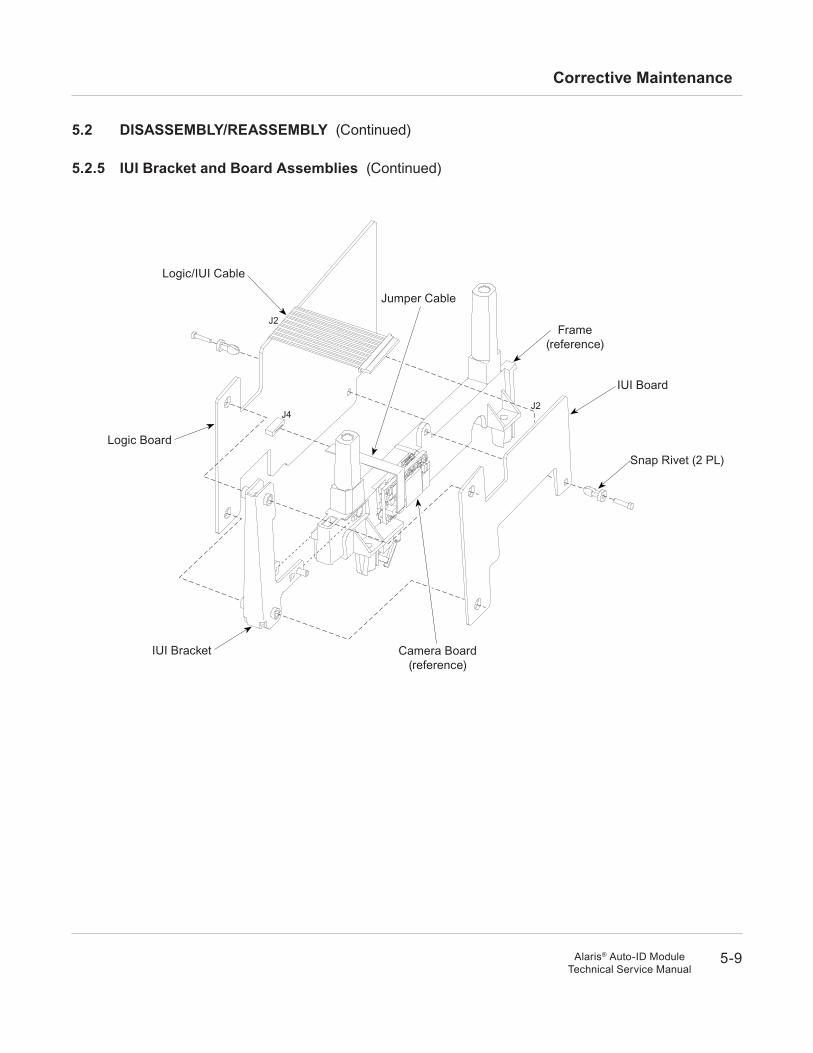
5.2.5 IuI Bracket and Board assemblies
IMPOrTanT: If the Jumper Cable, Camera/Frame Assembly or Logic Board needs to be replaced, identify the connector contact material before ordering a replacement. These parts are no longer being produced with lead contacts and cannot be mixed with the replacement gold contact parts. Lead versus gold contacts can be identified visually or by the "REF" number on the bar code / serial number label (on rear of instrument).
Contacts REF NumberLead 10016166 or lowerGold 10372286 or higher
If these parts are identified as having lead contacts and any of them need to be replaced, return the instrument to the factory for repair.
1. Disconnect Logic/IUI Cable from Logic Board J2.
2. Use small diagonal cutter to lift and remove plastic Snap Rivet attaching IUI Board to Frame.
3. Disconnect Jumper Cable from Logic Board J4.
4. Use small diagonal cutter to lift and remove Snap Rivet attaching Logic Board to Frame.
5. Detach IUI Bracket from Frame.
during reassembly:
• IMPOrTanT: Ensure Jumper Cable and cable's connectors on Logic Board and Camera Board all have same contact material. Do not mix gold contacts (new) with lead contacts (old).
• Frame and IUI Bracket snap together.
• When reconnecting cables, use an orange stick or similar tool to ensure cables are securely seated into connectors.
• When reconnecting Jumper Cable, ensure cable markings and black side of cable face away from Camera Assembly.
CauTIOnDo not cut rivet.
CauTIOnDo not cut rivet.
5-9
Corrective Maintenance
Alaris® Auto-ID ModuleTechnical Service Manual
5.2 dISaSSeMBly/reaSSeMBly (Continued)
5.2.5 IuI Bracket and Board assemblies (Continued)
J4J2
J2Frame
(reference)
Logic/IUI Cable
Jumper Cable
Snap Rivet (2 PL)
Logic Board
IUI Board
IUI Bracket Camera Board(reference)
5-10
Corrective Maintenance
Alaris® Auto-ID ModuleTechnical Service Manual
5.2 dISaSSeMBly/reaSSeMBly (Continued)
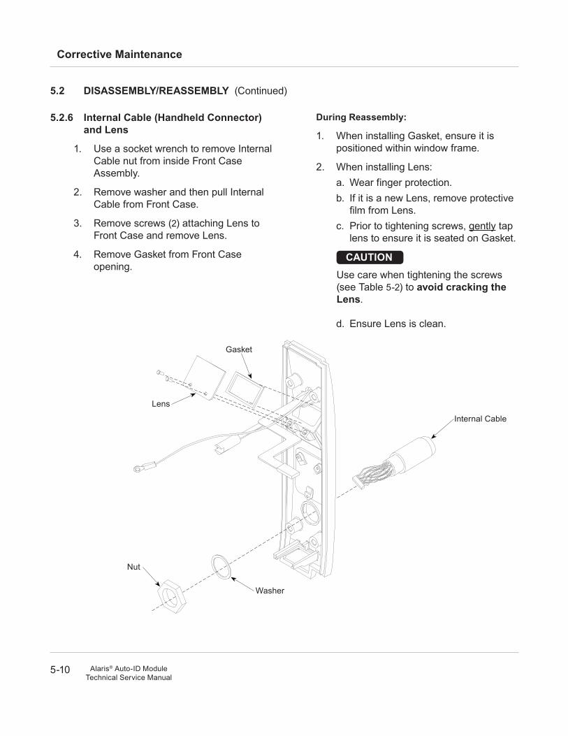
5.2.6 Internal Cable (handheld Connector) and lens
1. Use a socket wrench to remove Internal Cable nut from inside Front Case Assembly.
2. Remove washer and then pull Internal Cable from Front Case.
3. Remove screws (2) attaching Lens to Front Case and remove Lens.
4. Remove Gasket from Front Case opening.
during reassembly:
1. When installing Gasket, ensure it is positioned within window frame.
2. When installing Lens:a. Wear finger protection.b. If it is a new Lens, remove protective
film from Lens.c. Prior to tightening screws, gently tap
lens to ensure it is seated on Gasket.
d. Ensure Lens is clean.
CauTIOnUse care when tightening the screws (see Table 5-2) to avoid cracking the lens.
Internal Cable
Lens
Gasket
Nut
Washer
5-11
Corrective Maintenance
Alaris® Auto-ID ModuleTechnical Service Manual
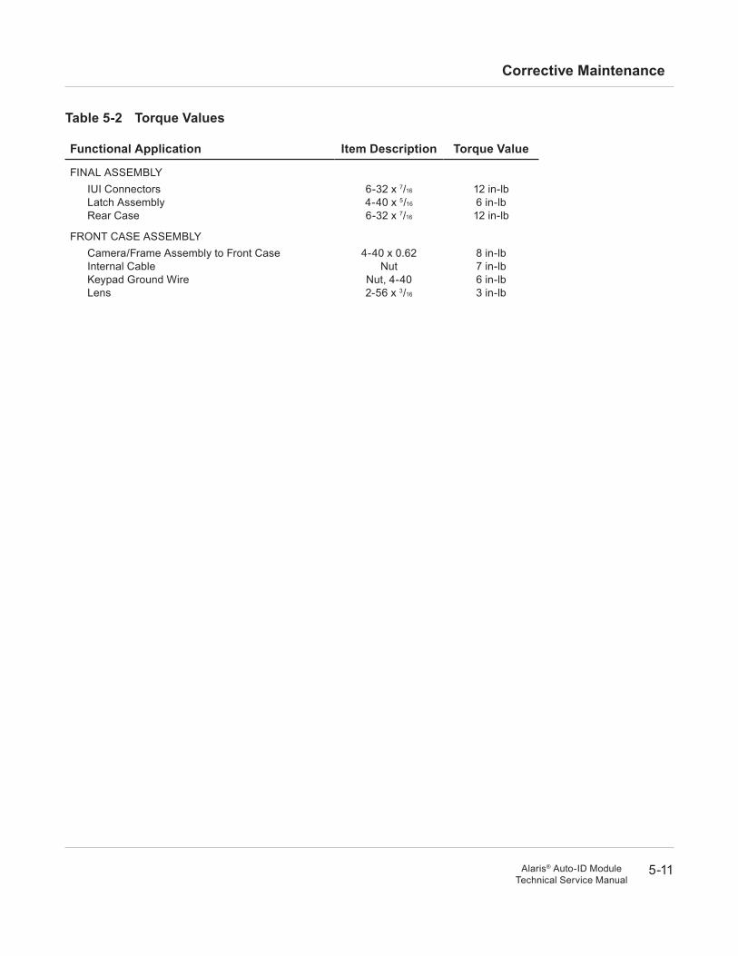
Table 5-2 Torque Values
Functional application Item description Torque Value
FINAL ASSEMBLyIUI ConnectorsLatch AssemblyRear Case
6-32 x 7/16
4-40 x 5/16
6-32 x 7/16
12 in-lb6 in-lb12 in-lb
FRONT CASE ASSEMBLyCamera/Frame Assembly to Front CaseInternal CableKeypad Ground WireLens
4-40 x 0.62Nut
Nut, 4-402-56 x 3/16
8 in-lb7 in-lb6 in-lb3 in-lb
5-12
Corrective Maintenance
Alaris® Auto-ID ModuleTechnical Service Manual
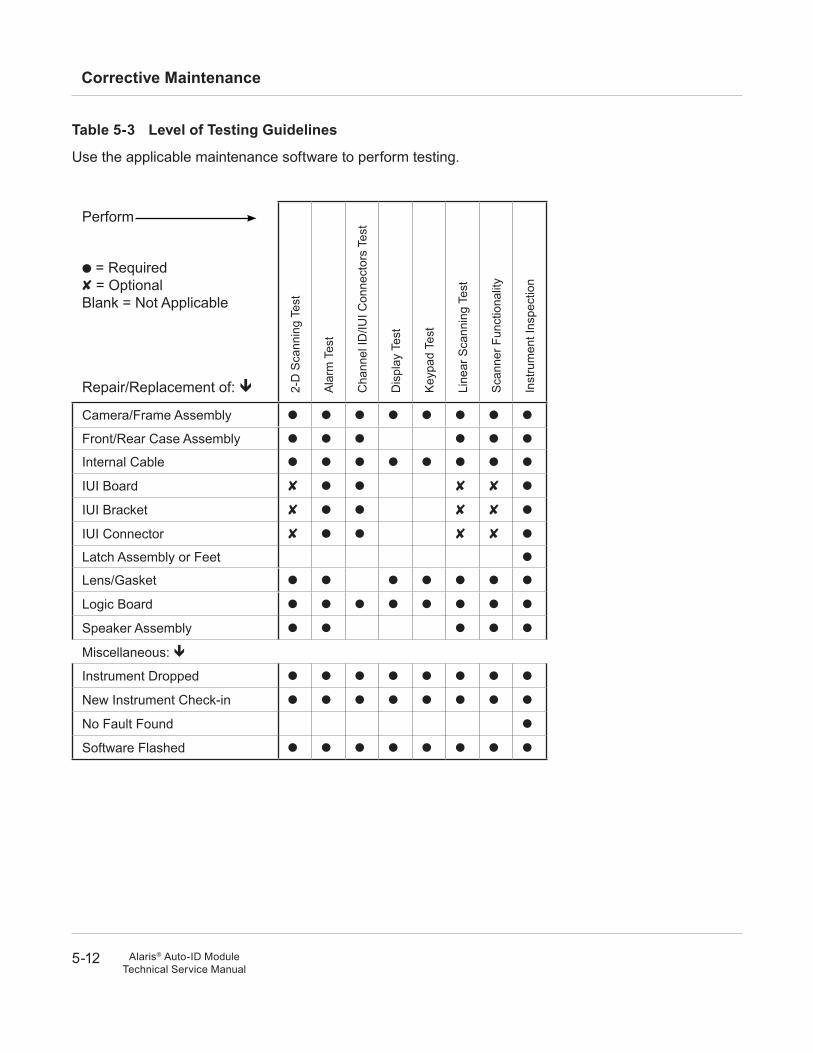
Table 5-3 level of Testing Guidelines
Use the applicable maintenance software to perform testing.
Perform
l = Required8 = OptionalBlank = Not Applicable
Repair/Replacement of: ê 2-D
Sca
nnin
g Te
st
Ala
rm T
est
Cha
nnel
ID/IU
I Con
nect
ors
Test
Dis
play
Tes
t
Key
pad
Test
Line
ar S
cann
ing
Test
Sca
nner
Fun
ctio
nalit
y
Inst
rum
ent I
nspe
ctio
n
Camera/Frame Assembly l l l l l l l l
Front/Rear Case Assembly l l l l l l
Internal Cable l l l l l l l l
IUI Board 8 l l 8 8 l
IUI Bracket 8 l l 8 8 l
IUI Connector 8 l l 8 8 l
Latch Assembly or Feet l
Lens/Gasket l l l l l l l
Logic Board l l l l l l l l
Speaker Assembly l l l l l
Miscellaneous: ê
Instrument Dropped l l l l l l l l
New Instrument Check-in l l l l l l l l
No Fault Found l
Software Flashed l l l l l l l l

6 T
RO
UB
LE
SH
OO
TIN
G
6-1Alaris® Auto-ID ModuleTechnical Service Manual
6.1 InTrOduCTIOn
This chapter contains possible technical problems that can occur while using the Auto-ID Module. See this chapter before attempting to service the Auto-ID Module. Refer to the PC Unit/Pump Module Technical Service Manual for Alaris® System information.
Use the information in this chapter to help diagnose and correct technical problems. Use the applicable maintenance software to perform required tests.
6.2 General TrOuBleShOOTInG
For the Alaris® System to function properly with the Auto-ID Module:
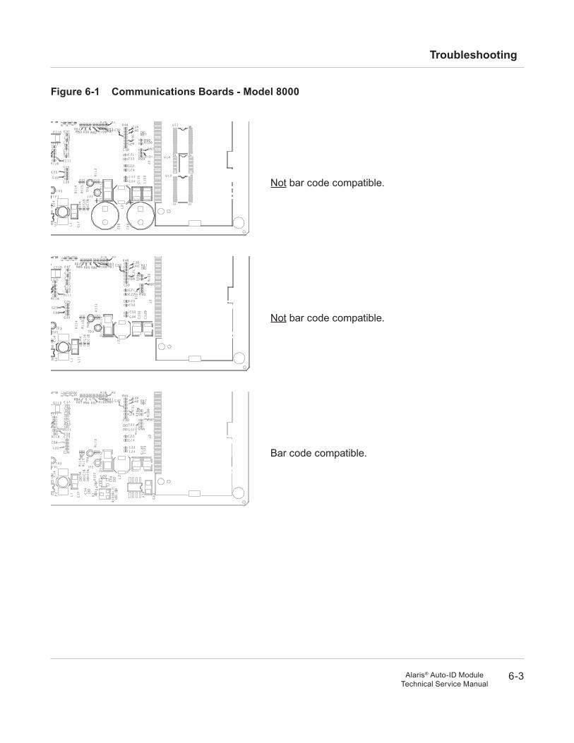
nOTe: The PC Unit will not recognize the Auto-ID Module if the software and Communications Interface Board (CIB) are not compatible.
• Auto-ID Module software must be 8.5.26.0 or later. Auto-ID Module, PC Unit and Wireless Main software must be compatible (see Table 6-1).
• Model 8000: CIB must be bar code compatible (see Figure 6-1).
• Default parsing rules (Auto-ID settings configured on PC Unit) must be set (using applicable maintenance software) to translate patient or clinician ID bar codes. Once settings are configured, IDs can be scanned to verify proper operation, even without a pumping module being attached.
CauTIOnClass 1 LED devices are safe under reasonably foreseeable conditions of operation, including the use of optical instruments for intrabeam viewing. To avoid potential harm, avoid looking into the beam.
Chapter 6 – Troubleshooting
6-2
Troubleshooting
Alaris® Auto-ID ModuleTechnical Service Manual
6.2 General TrOuBleShOOTInG (Continued)
• Data Set must have been wirelessly downloaded to PC Unit, and have proper aliases and/or NDCs set up for drugs. Once this is accomplished, scanner light comes on when a pumping module channel is accessed to set up a drug.
nOTe: To help determine whether or not a problem is related to the Data Set, it would be helpful to track (if possible) when a new Data Set is downloaded.
• A Pump Module, Syringe Module, or PCA Module must be attached as part of Alaris® System.
• PC Unit, pumping module, Auto-ID Module, and handheld scanner must be properly and securely connected.
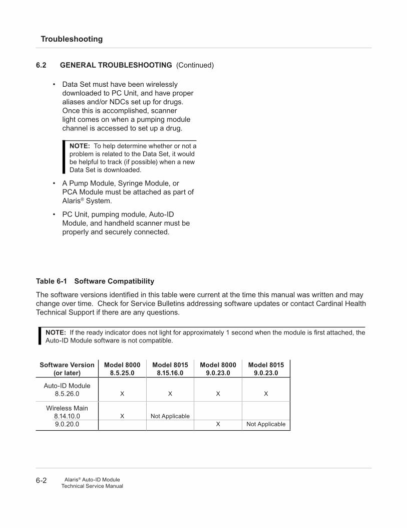
Table 6-1 Software Compatibility
The software versions identified in this table were current at the time this manual was written and may change over time. Check for Service Bulletins addressing software updates or contact Cardinal Health Technical Support if there are any questions.
nOTe: If the ready indicator does not light for approximately 1 second when the module is first attached, the Auto-ID Module software is not compatible.
Software Version (or later)
Model 80008.5.25.0
Model 80158.15.16.0
Model 80009.0.23.0
Model 80159.0.23.0
Auto-ID Module8.5.26.0 X X X X
Wireless Main8.14.10.09.0.20.0
X Not ApplicableX Not Applicable
6-3
Troubleshooting
Alaris® Auto-ID ModuleTechnical Service Manual
Figure 6-1 Communications Boards - Model 8000
Not bar code compatible.
Not bar code compatible.
Bar code compatible.
6-4
Troubleshooting
Alaris® Auto-ID ModuleTechnical Service Manual
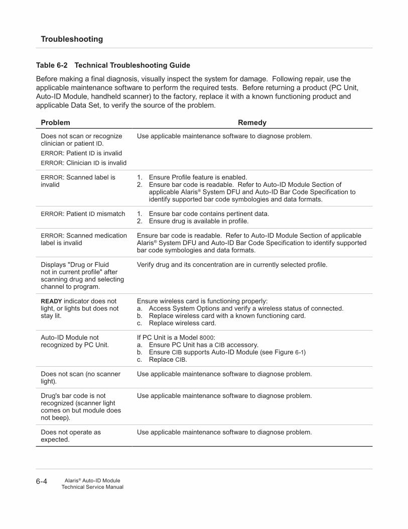
Table 6-2 Technical Troubleshooting Guide
Before making a final diagnosis, visually inspect the system for damage. Following repair, use the applicable maintenance software to perform the required tests. Before returning a product (PC Unit, Auto-ID Module, handheld scanner) to the factory, replace it with a known functioning product and applicable Data Set, to verify the source of the problem.
Problem remedy
Does not scan or recognize clinician or patient ID.ERROR: Patient ID is invalidERROR: Clinician ID is invalid
Use applicable maintenance software to diagnose problem.
ERROR: Scanned label is invalid
1. Ensure Profile feature is enabled.2. Ensure bar code is readable. Refer to Auto-ID Module Section of
applicable Alaris® System DFU and Auto-ID Bar Code Specification to identify supported bar code symbologies and data formats.
ERROR: Patient ID mismatch 1. Ensure bar code contains pertinent data.2. Ensure drug is available in profile.
ERROR: Scanned medication label is invalid
Ensure bar code is readable. Refer to Auto-ID Module Section of applicable Alaris® System DFU and Auto-ID Bar Code Specification to identify supported bar code symbologies and data formats.
Displays "Drug or Fluid not in current profile" after scanning drug and selecting channel to program.
Verify drug and its concentration are in currently selected profile.
ready indicator does not light, or lights but does not stay lit.
Ensure wireless card is functioning properly:a. Access System Options and verify a wireless status of connected.b. Replace wireless card with a known functioning card.c. Replace wireless card.
Auto-ID Module not recognized by PC Unit.
If PC Unit is a Model 8000:a. Ensure PC Unit has a CIB accessory.b. Ensure CIB supports Auto-ID Module (see Figure 6-1)c. Replace CIB.
Does not scan (no scanner light).
Use applicable maintenance software to diagnose problem.
Drug's bar code is not recognized (scanner light comes on but module does not beep).
Use applicable maintenance software to diagnose problem.
Does not operate as expected.
Use applicable maintenance software to diagnose problem.
6-5
Troubleshooting
Alaris® Auto-ID ModuleTechnical Service Manual
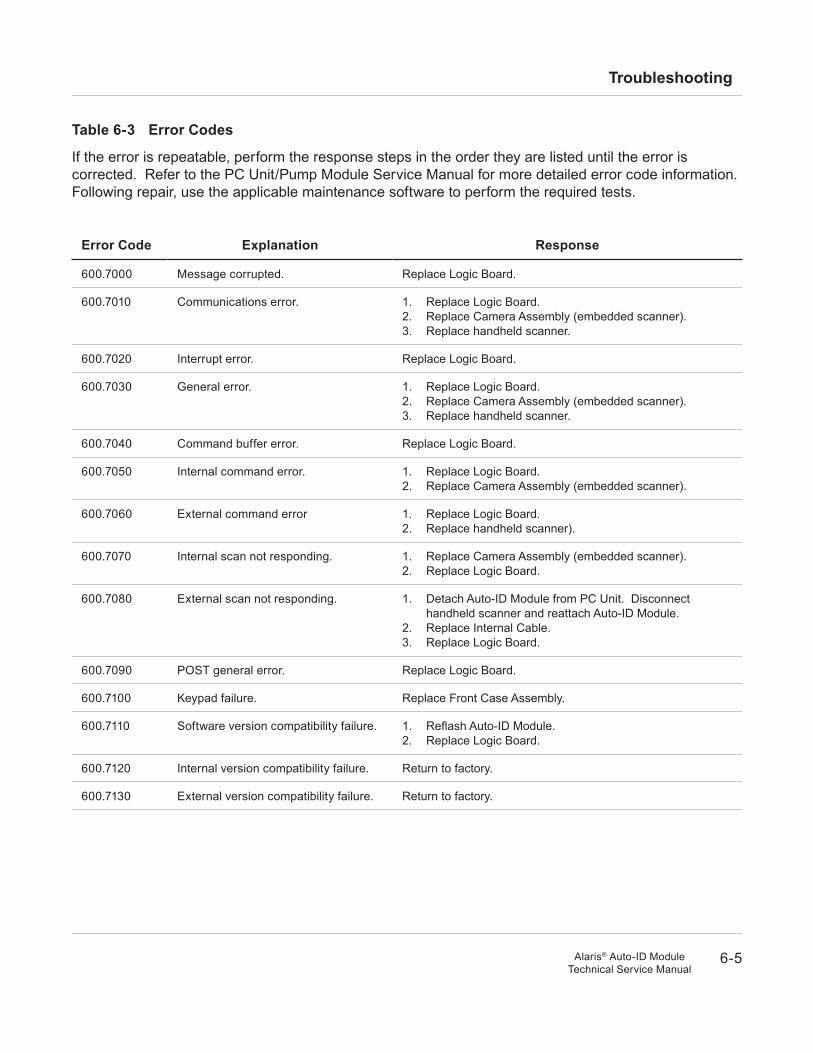
Table 6-3 error Codes
If the error is repeatable, perform the response steps in the order they are listed until the error is corrected. Refer to the PC Unit/Pump Module Service Manual for more detailed error code information. Following repair, use the applicable maintenance software to perform the required tests.
error Code explanation response
600.7000 Message corrupted. Replace Logic Board.
600.7010 Communications error. 1. Replace Logic Board.2. Replace Camera Assembly (embedded scanner).3. Replace handheld scanner.
600.7020 Interrupt error. Replace Logic Board.
600.7030 General error. 1. Replace Logic Board.2. Replace Camera Assembly (embedded scanner).3. Replace handheld scanner.
600.7040 Command buffer error. Replace Logic Board.
600.7050 Internal command error. 1. Replace Logic Board.2. Replace Camera Assembly (embedded scanner).
600.7060 External command error 1. Replace Logic Board.2. Replace handheld scanner).
600.7070 Internal scan not responding. 1. Replace Camera Assembly (embedded scanner).2. Replace Logic Board.
600.7080 External scan not responding. 1. Detach Auto-ID Module from PC Unit. Disconnect handheld scanner and reattach Auto-ID Module.
2. Replace Internal Cable.3. Replace Logic Board.
600.7090 POST general error. Replace Logic Board.
600.7100 Keypad failure. Replace Front Case Assembly.
600.7110 Software version compatibility failure. 1. Reflash Auto-ID Module.2. Replace Logic Board.
600.7120 Internal version compatibility failure. Return to factory.
600.7130 External version compatibility failure. Return to factory.

6-6
Troubleshooting
Alaris® Auto-ID ModuleTechnical Service Manual
THIS PAGEINTENTIONALLy
LEFT BLANK

7 IL
LU
ST
RA
TE
D P
AR
TS
BR
EA
KD
OW
N
7-1Alaris® Auto-ID ModuleTechnical Service Manual
7.1 InTrOduCTIOn
The illustrated parts breakdown is divided into major assemblies and individual parts.
7.2 IlluSTraTIOnS
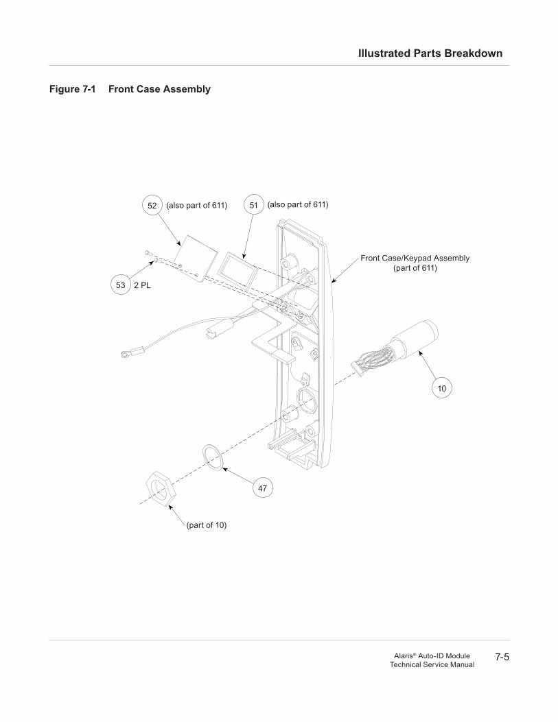
The exploded views serve as visual aids for identifying the parts of each assembly. If a part/assembly is identified with an item number (appearing in a bubble), that number corresponds with the item number on the parts list. If a part/assembly is not identified with an item number, it is available only as part of a higher assembly or kit.
Due to product changes over time, components/assemblies illustrated in this chapter may differ from the instrument being serviced.
7.3 ParTS lIST
The parts list provides the following information for saleable parts and assemblies:
Item: This number corresponds with number in illustration.
Part number: This is the Alaris® product number needed when placing an order.
When a part number is not provided, that part is either not sold by Cardinal Health, is provided as part of a kit or higher assembly, or can only be replaced/repaired by Cardinal Health authorized service personnel.
description: Descriptive information that may be helpful when placing an order.
QTy: Total number of each item used.
Chapter 7 – Illustrated Parts Breakdown
7-2
Illustrated Parts Breakdown
Alaris® Auto-ID ModuleTechnical Service Manual
7.4 OrderInG ParTS
Parts can be ordered by writing or calling Cardinal Health Customer Care (see "General Contact Information" at the beginning of this manual). When requesting a part, provide the following information:
• Product name and model number (for example, Auto-ID Module, Model 8600).
• Part number.
• Part description, as provided in parts list.
• For labels, specify required language.
7-3
Illustrated Parts Breakdown
Alaris® Auto-ID ModuleTechnical Service Manual
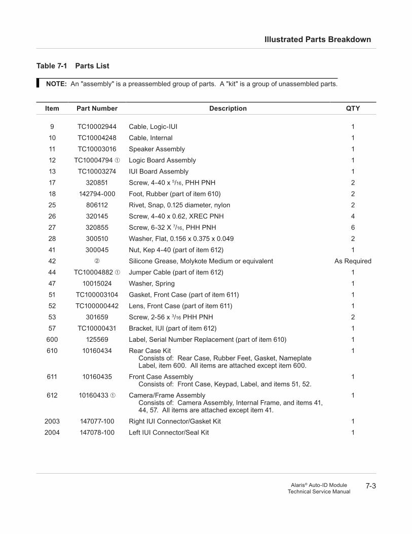
Table 7-1 Parts list
nOTe: An "assembly" is a preassembled group of parts. A "kit" is a group of unassembled parts.
Item Part number description QTy
9 TC10002944 Cable, Logic-IUI 1
10 TC10004248 Cable, Internal 1
11 TC10003016 Speaker Assembly 1
12 TC10004794 Logic Board Assembly 1
13 TC10003274 IUI Board Assembly 1
17 320851 Screw, 4-40 x 5/16, PHH PNH 2
18 142794-000 Foot, Rubber (part of item 610) 2
25 806112 Rivet, Snap, 0.125 diameter, nylon 2
26 320145 Screw, 4-40 x 0.62, XREC PNH 4
27 320855 Screw, 6-32 X 7/16, PHH PNH 6
28 300510 Washer, Flat, 0.156 x 0.375 x 0.049 2
41 300045 Nut, Kep 4-40 (part of item 612) 1
42 Silicone Grease, Molykote Medium or equivalent As Required
44 TC10004882 Jumper Cable (part of item 612) 1
47 10015024 Washer, Spring 1
51 TC100003104 Gasket, Front Case (part of item 611) 1
52 TC100000442 Lens, Front Case (part of item 611) 1
53 301659 Screw, 2-56 x 3/16 PHH PNH 2
57 TC10000431 Bracket, IUI (part of item 612) 1
600 125569 Label, Serial Number Replacement (part of item 610) 1
610 10160434 Rear Case KitConsists of: Rear Case, Rubber Feet, Gasket, Nameplate Label, item 600. All items are attached except item 600.
1
611 10160435 Front Case AssemblyConsists of: Front Case, Keypad, Label, and items 51, 52.
1
612 10160433 Camera/Frame AssemblyConsists of: Camera Assembly, Internal Frame, and items 41, 44, 57. All items are attached except item 41.
1
2003 147077-100 Right IUI Connector/Gasket Kit 1
2004 147078-100 Left IUI Connector/Seal Kit 1
7-4
Illustrated Parts Breakdown
Alaris® Auto-ID ModuleTechnical Service Manual
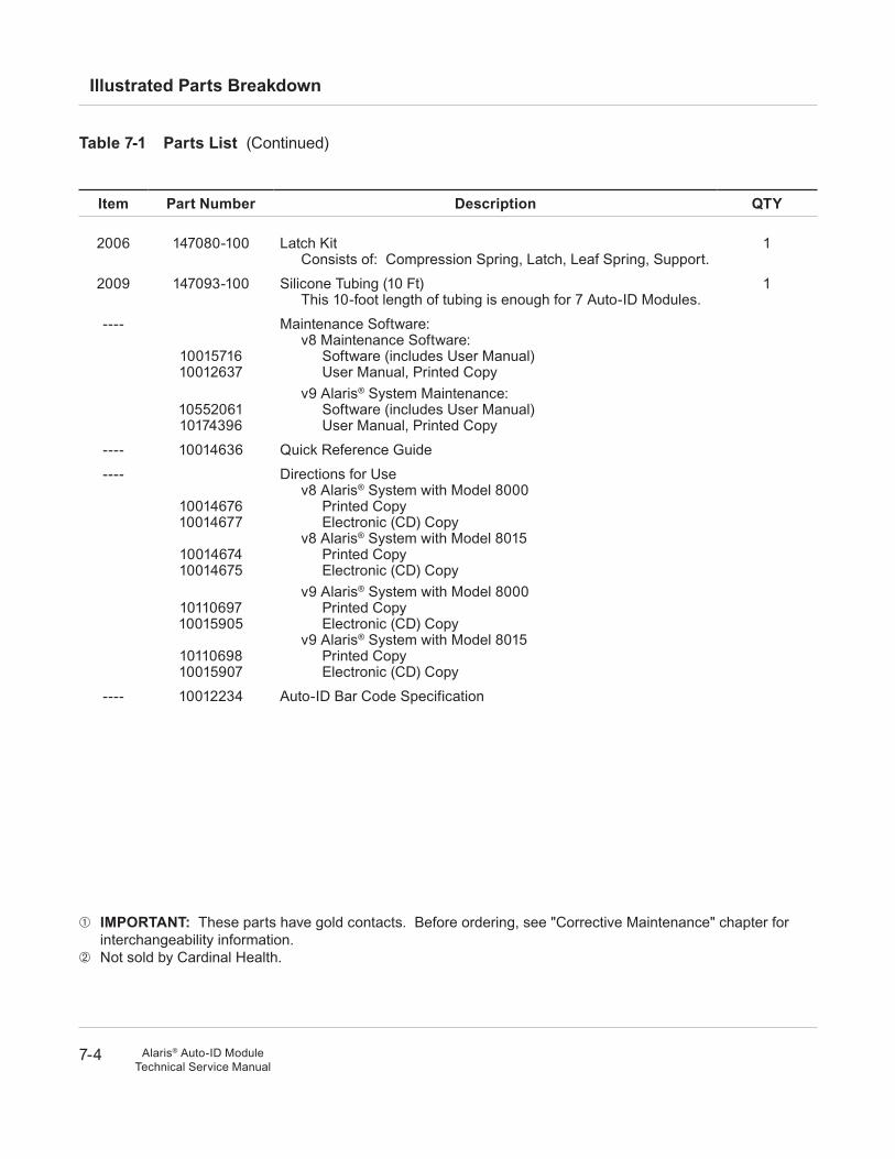
Table 7-1 Parts list (Continued)
Item Part number description QTy
2006 147080-100 Latch KitConsists of: Compression Spring, Latch, Leaf Spring, Support.
1
2009 147093-100 Silicone Tubing (10 Ft)This 10-foot length of tubing is enough for 7 Auto-ID Modules.
1
----
1001571610012637
1055206110174396
Maintenance Software:v8 Maintenance Software:
Software (includes User Manual)User Manual, Printed Copy
v9 Alaris® System Maintenance:Software (includes User Manual)User Manual, Printed Copy
---- 10014636 Quick Reference Guide
----
1001467610014677
1001467410014675
1011069710015905
1011069810015907
Directions for Usev8 Alaris® System with Model 8000
Printed CopyElectronic (CD) Copy
v8 Alaris® System with Model 8015Printed CopyElectronic (CD) Copy
v9 Alaris® System with Model 8000Printed CopyElectronic (CD) Copy
v9 Alaris® System with Model 8015Printed CopyElectronic (CD) Copy
---- 10012234 Auto-ID Bar Code Specification
IMPOrTanT: These parts have gold contacts. Before ordering, see "Corrective Maintenance" chapter for interchangeability information.
Not sold by Cardinal Health.
7-5
Illustrated Parts Breakdown
Alaris® Auto-ID ModuleTechnical Service Manual
Figure 7-1 Front Case assembly
2 PL53
52
10
47
(part of 10)
(also part of 611) (also part of 611)51
Front Case/Keypad Assembly(part of 611)
7-6
Illustrated Parts Breakdown
Alaris® Auto-ID ModuleTechnical Service Manual
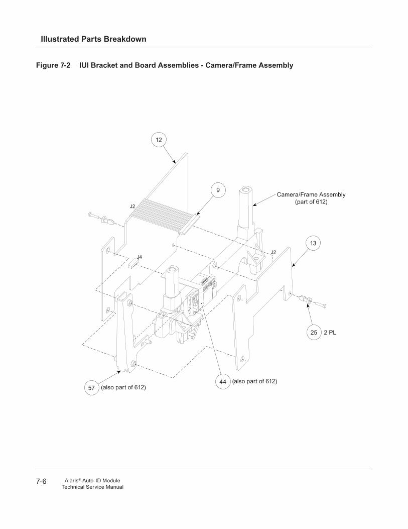
Figure 7-2 IuI Bracket and Board assemblies - Camera/Frame assembly
J4J2
J2
12
9
13
25
4457
(also part of 612)
2 PL
(also part of 612)
Camera/Frame Assembly(part of 612)
7-7
Illustrated Parts Breakdown
Alaris® Auto-ID ModuleTechnical Service Manual
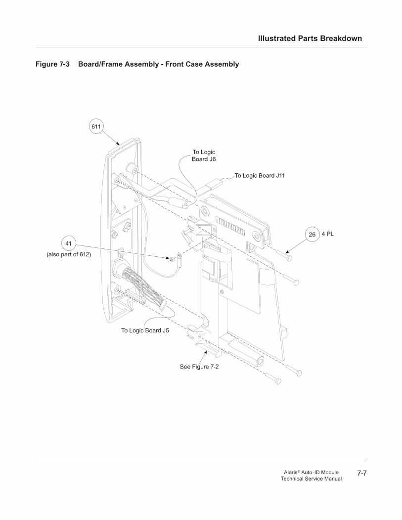
Figure 7-3 Board/Frame assembly - Front Case assembly
2641
To Logic Board J11
(also part of 612)
4 PL
To Logic Board J5
To Logic Board J6
611
See Figure 7-2
7-8
Illustrated Parts Breakdown
Alaris® Auto-ID ModuleTechnical Service Manual
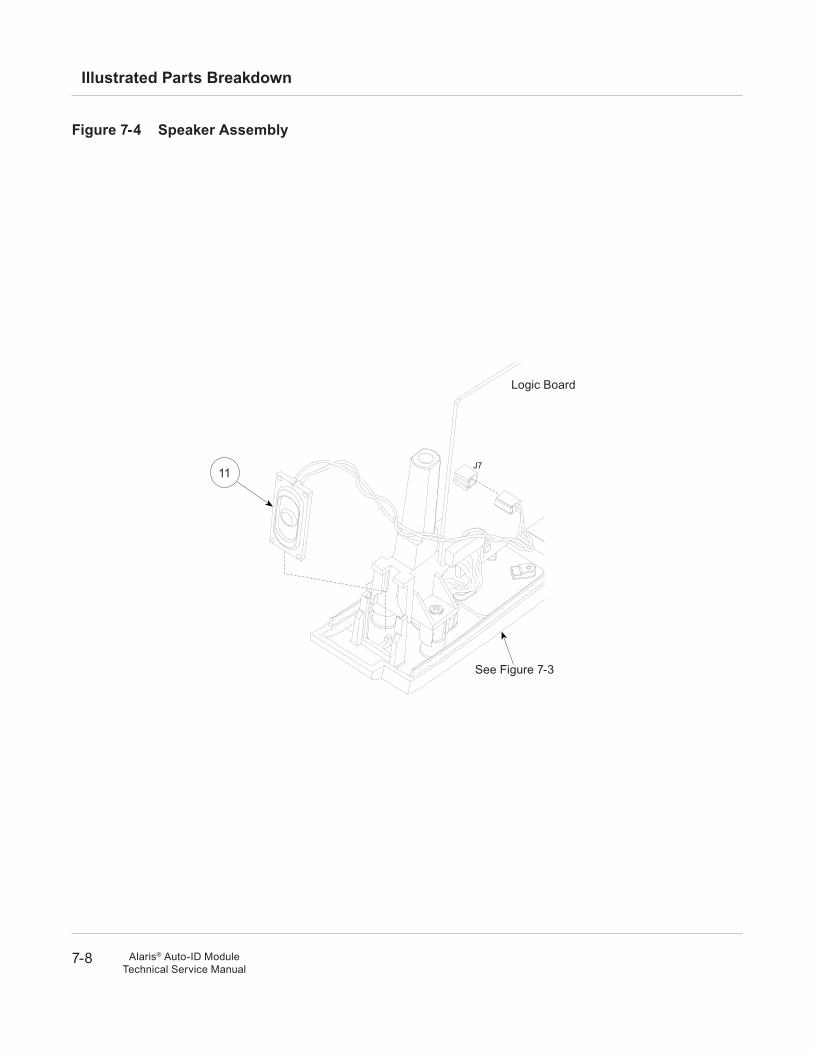
J7
Figure 7-4 Speaker assembly
11
Logic Board
See Figure 7-3
7-9
Illustrated Parts Breakdown
Alaris® Auto-ID ModuleTechnical Service Manual
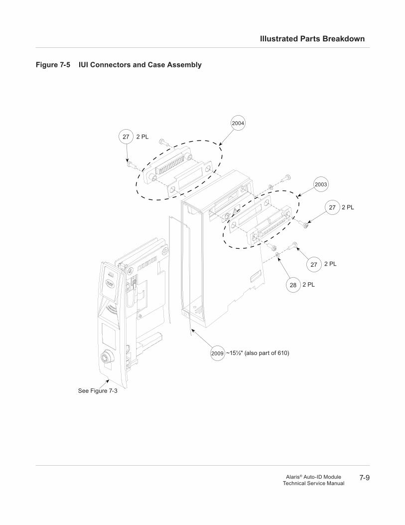
Figure 7-5 IuI Connectors and Case assembly
READY
SCANCANCEL
See Figure 7-3
27
27
27
28
2009
2004
2003
2 PL
2 PL
2 PL
2 PL
~15½" (also part of 610)
7-10
Illustrated Parts Breakdown
Alaris® Auto-ID ModuleTechnical Service Manual
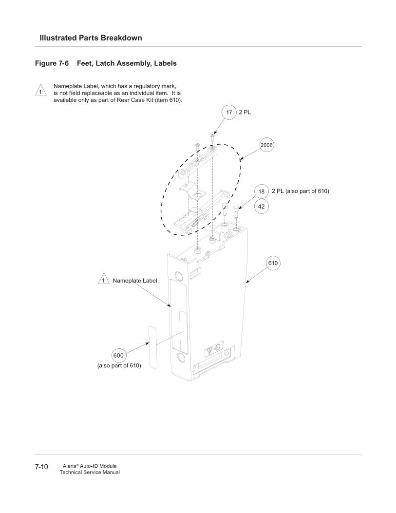
Figure 7-6 Feet, latch assembly, labels
1Nameplate Label, which has a regulatory mark, is not field replaceable as an individual item. It is available only as part of Rear Case Kit (item 610).
Nameplate Label1
600
610
18
42
2 PL (also part of 610)
2 PL17
2006
(also part of 610)
7-11
Illustrated Parts Breakdown
Alaris® Auto-ID ModuleTechnical Service Manual
J2
J1
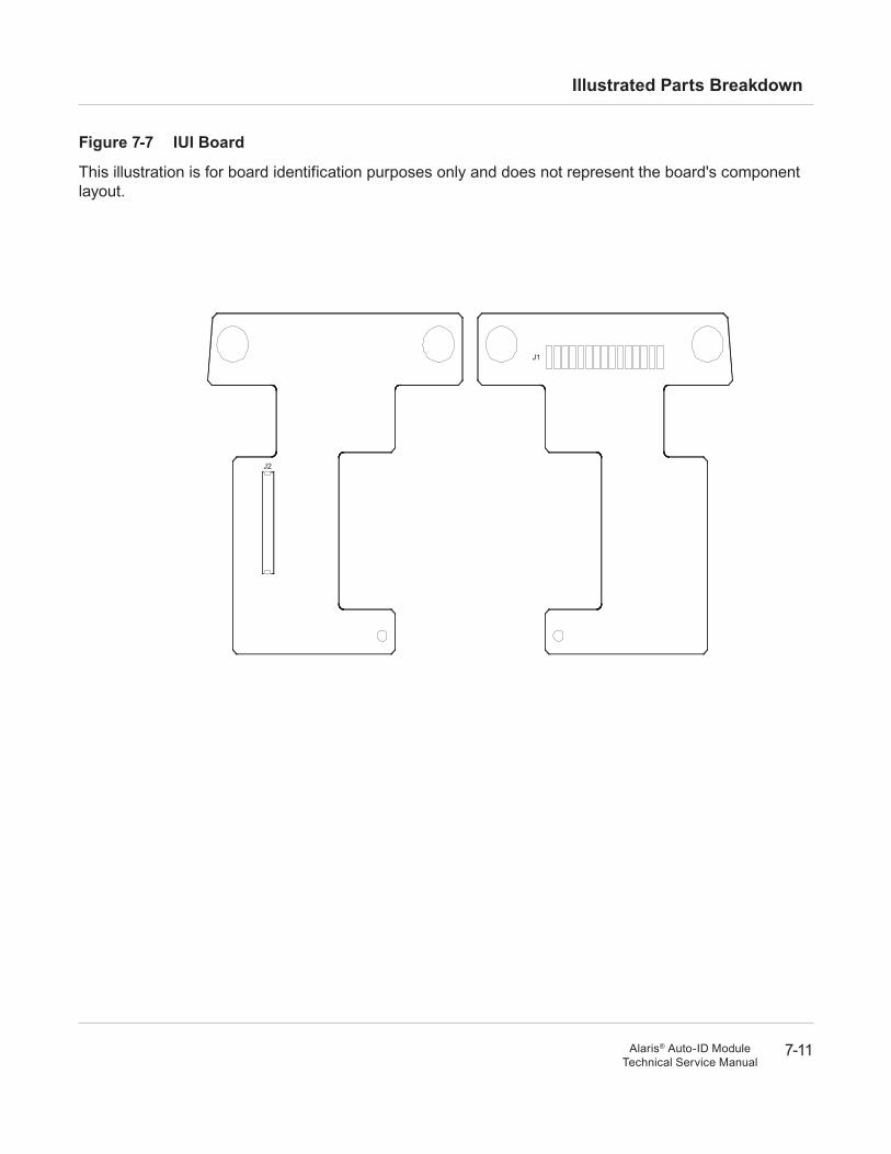
Figure 7-7 IuI Board
This illustration is for board identification purposes only and does not represent the board's component layout.
7-12
Illustrated Parts Breakdown
Alaris® Auto-ID ModuleTechnical Service Manual
J1
J2
J3
J11
J6
J10
J12 J7
J5
J4
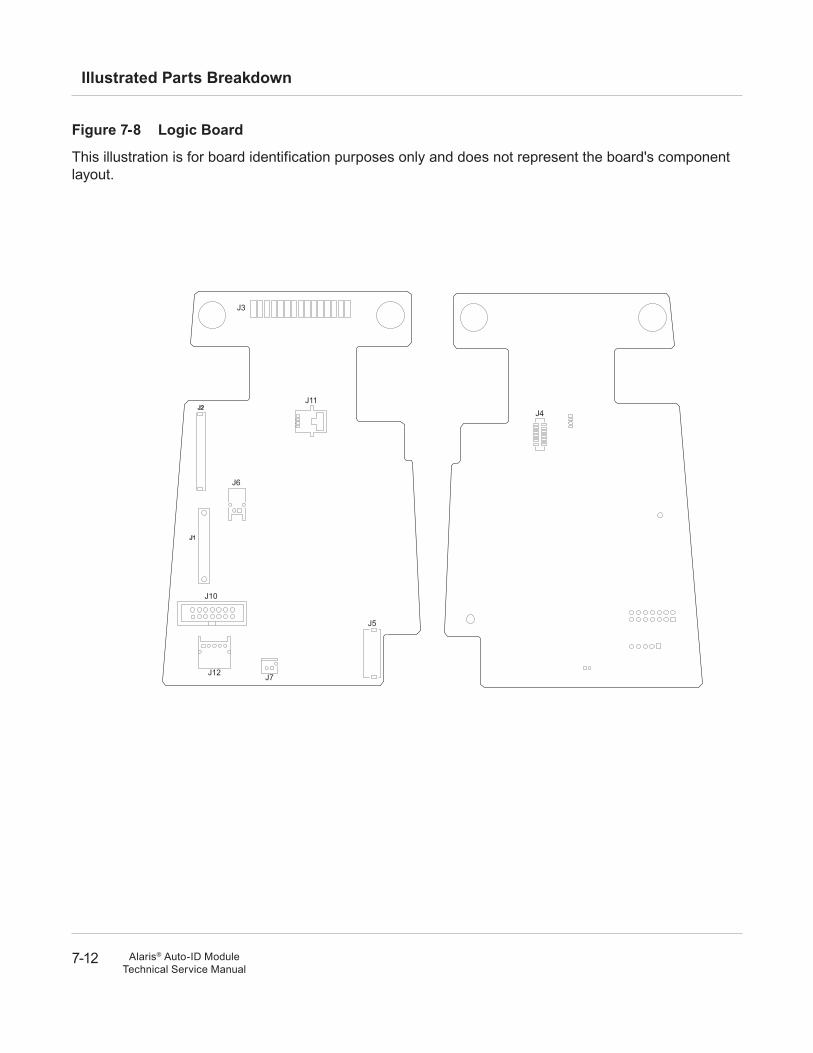
Figure 7-8 logic Board
This illustration is for board identification purposes only and does not represent the board's component layout.


Part Number 10099175 ©2007 Cardinal Health, Inc. or one of its subsidiaries. All rights reserved.
Alaris® and Guardrails® are registered trademarks of Cardinal Health, Inc. or one of its subsidiaries. All other trademarks belong to their respective owners.