Embed Size (px)
Citation preview

Technical Review of NEERI & NGRI Reports:
‘Assessment and Remediation of Hazardous Waste
Contaminated Areas in and around M/s Union
Carbide India Ltd., Bhopal’ (NEERI)
and
‘Geophysical Investigations to Assess Industrial Waste Dumped at UCIL, Bhopal’ (NGRI)
Authors
Dr. Stuart Gray
Jarlath Hynes
Joe Jackson
Dr. Jurgen Porst
The contributions made by Will Nicholls of Beyond Bhopal and Colin Toogood and Tim Edwards of the Bhopal Medical Appeal, UK in coordination and preparation of the report is gratefully acknowledged by the Bhopal survivors’ organizations.
1

Contents1.0Intoducton ................................................................................................................................................................. 3 2.0 Suitability of complet d asse s sment ............................................................................................................. 4 2.1 Model Approach ....................................................................................................................................................... 4
2.2 Insufcient NEERI desk tp study/ absence of Sampling and Analysis Plan ....................... 5 2.3 Use and Intrpretaton of Geophysical Data ....................................................................................... 7 2.4 Intrpretaton of Geology and Hydrogeological Regime ................................................................. 7 2.4 Qualit Issues ...................................................................................................................................................... 9
3.0 Suitabilit of Remedial Proposals ................................................................................................................. 11 4.0 Identfcaton of Key Issues raised by te report ................................................................................... 13 5.0 Recommendat ons for Furter Work .......................................................................................................... 14 References : ..................................................................................................................................................................... 16 Appendix 2 ...................................................................................................................................................................... 19 Appendix 3 ...................................................................................................................................................................... 21 Appendix 4 ...................................................................................................................................................................... 21
Overall Comments
This document presents a critical review of the NEERI and NGRI reports published in June 2010. It is being submitted following the invitation for comments extended by the Chairman, Bhopal Environmental Remediation Oversight Committee and Minister of State, Ministry of Environment and Forests, Government of India to the Bhopal survivors’ organizations on July 9, 2010 during a meeting held in Bhopal.
Both the NEERI and the NGRI report provide useful information, however, a number of key deficiencies have been identified in the site investigations and methodologies used. Critical results are misinterpreted, or missing, and a number of the conclusions reached, within the reports, are not supported by the evidence presented.
The scarcity of groundwater sampling, the absence of detailed investigation of the Solar Evaporation Ponds, false assumptions regarding groundwater flow direction, and the identified permeable nature of the black cotton soil all suggest that NEERI's conclusion that groundwater has not been contaminated from Union Carbide factory sources cannot be supported.
NEERI conducted a limited sampling campaign that was compromised and did not present analytical results for key contaminants of concern. Despite acknowledging the contamination found by previous investigations, NEERI did not follow-up these leads. Where groundwater contamination was detected, no explanation or theories were offered as to the source of this contamination.
Analysis of the geophysical data provided show that NEERI’s attempt to quantify the soils requiring remediation based purely on the estimated fill depth is overly simplistic. At this time
2

we still do not know how many aquifers there are, the groundwater flow direction in each, how they are recharged, and where they outcrop.
Overall, the current site assessment can only regarded as preliminary to a complete site investigation conducted to the highest international standards.
1.0 IntroductionThis report is a review of the following documents:
• Assessment and Remediation of Hazardous Waste Contaminated Areas in and around M/s Union Carbide India Ltd., Bhopal. (Sponsored by: Bhopal Gas Tragedy Relief and Rehabilitation Department Govt. of Madhya Pradesh, Bhopal) By National Environmental Engineering Research Institute Nehru Marg, Nagpur;
• Geophysical Investigations To Assess Industrial Waste Dumped At UCIL, Bhopal (Union Carbide India Ltd.) By National Geophysical Research Institute, Hyderabad. Ref: GAP 401 28(VSS).
These reports are referred to here as the NEERI report and the NGRI report respectively.
The basis of this assessment is to consider the following:
1. Suitability of completed assessment;
2. Discussion of quality issues and constraints;
3. Suitability of Remedial proposals;
4. Identification of key issues raised by the report;
5. Recommendations for further work.
The NEERI/NGRI reports look at the contamination of soil and groundwater, in and around the Union Carbide factory premises, due to the known dumping of toxic wastes at the Union Carbide factory site during operations and subsequent to its closure. Thus a degree of separation is needed between this issue and the Union Carbide gas disaster of December 1984. There are significant ‘legacy contamination’ issues, caused by other chemicals dumped as waste, that still pose a significant threat to human health and the environment.
NEERI’s report acknowledges that toxic wastes from production and related processes, were dumped both on the factory premises and just outside in three Solar Evaporation Ponds (SEPs). This information is consistent with the subsequent detection of these same substances in soil and water samples by other investigators (CSE 2009, BMA 2009, Greenpeace 1999-2004, Shristi 2002, Dikhshith et al 1990, MPPCB 2003-2006, Citizens Environmental Laboratory 1990) and strongly suggest that the groundwater has been, and continues to be, contaminated by these same substances.
3

2.0 Suitability of completed assessmentA review of the reports shows that the combined efforts of the NEERI and NGRI reports have broadly followed the following rationale:
• Summarise findings of selected historic reports;
• Geophysical (non-intrusive) investigation of selected areas to determine the depth of fill areas;
• Target shallow soil sampling based on the suspected dump areas revealed by geophysical survey (27nos. Surface and subsurface soil samples taken for analysis);
• Further soil sampling outside of Union Carbide factory (8nos. Locations and a total of 24nos. Samples collected);
• Drilling of 5nos. Boreholes (No’s A to E) and soil logging, sampling and chemical analysis;
• Development and monitoring of drilled wells and a further 8 nos. Wells in the vicinity of the site;
• Preliminary testing of hydrogeological properties using slug tests in wells A to E
• Analysis of soil samples for contaminants detected in previous investigations, as discussed by NEERI. See Appendix 1.
• Define the hydrogeological regime at the site;• Make recommendations for suitable remediation actions and provide a guide on potential
costs of those actions.
2.1 Model ApproachThe overall site assessment rationale does not conform to the approach generally adopted internationally, where a phased or tiered approach to site investigation and assessment is preferred (for example, in the UK, BS10175, 2001)
Particular elements of an investigation are managed pro–actively depending upon the findings of the previous phase. Subsequent phases can then be carefully targeted and this avoids unnecessary work being undertaken.
The phased approach typically consists of the following stages (BS10175, 2001):
Phase 1 Desk Study - Historical research and review of available information from sources such as archives, plans, records, previous study reports and test results. The desk study should examine the past activities at the site and assess them for potentially contaminative processes, determine the potential for the presence of contamination and identify the specific chemicals used/ disposed of at site, and collate existing evidence of any contamination. The report should also identify any potential receptors, e.g. humans, surface watercourses, aquifers, or ecological receptors and collate the information relating to the site’s environmental setting i.e. geology, hydrogeology and the location of potentially sensitive waters (lakes, ponds, rivers, springs, aquifers). This information is then used to undertake a qualitative risk assessment through the development of a conceptual model for the site. The conceptual model identifies any Significant Pollutant Linkages that may be present. If Significant Pollutant Linkages are present then a Phase 2 site investigation may be required to quantify the risk. The gathered desk study information can be used to target potential problem areas and identify specific contaminants of concern. This may be formally provided as a Sampling and Analysis Plan for implementation at Phase 2.
4

Phase 2 Intrusive Investigation - An intrusive site investigation is undertaken to investigate each aspect highlighted by the Phase 1 desk study, historical research, and walkover survey. This comprises exploratory holes constructed using the most appropriate method for the site to investigate the local subsurface strata.
The Phase 2 intrusive contaminated land investigation is designed and implemented using a variety of in situ exploratory methods, depending on factors such as sensitivity of the area, ground conditions (anticipated geology, hydrogeology, the expected presence of old foundations or other obstructions, which may have an impact on the technique selected), size of site and type of contaminants identified by the desk study as potentially present.
A systematic, grid-based sampling regime is necessary to map the true extent of soil contamination. The vertical and horizontal extent of soil and groundwater contamination must be delineated prior to the design of any remediation strategy. Additionally, where water contamination is suspected, semi-permanent water monitoring stations must be established in local communities.
Chemical analysis of soil and water/ groundwater samples for common contaminants (and particularly any specific contaminants identified at the Phase 1 assessment stage) is completed to establish the concentration and extent of any contamination present. A risk assessment, using the ‘source-pathway-receptor’ model, would then be carried out and this assessment may be qualitative where pollutant linkages can be discounted, or quantitative where a pollutant linkage is evidenced or cannot be discounted.
Phase 3 Remediation (Design, Execution and Validation) - If remediation is deemed necessary (i.e. quantitative risk assessment has identified any unacceptable risk), then a site-specific remediation methodology should be produced. This can include delineation of contamination hot spots, further soil sampling, chemical analysis and additional monitoring if more information is required to supplement the data from previous investigations. A wide range of remediation techniques are available and the methods chosen, whether involving removal or in-situ treatment, are dependent upon a range of factors including: contaminant type and distribution; environmental sensitivity of the site; intended end use; cost and timescale. Finally the site is re-assessed (post-remediation) to ensure that the objectives of the remediation have been met. This is evidenced in a ‘Completion Report’, normally made available to the relevant regulatory authorities and key stakeholders, for approval.
Arriving at an appropriate, comprehensive and cost-effective remediation strategy must be a science-based decision, as selecting unsuitable methods can lead to incomplete clean-up and exacerbation of contamination issues
Whilst some of these best practice approaches may have been adopted, there remain critical discrepancies which detract from the assessment to such a degree that the conclusions arrived at by NEERI are compromised and cannot be scientifically supported. These discrepancies are summarised below.
2.2 Insufficient NEERI desk top study/ absence of Sampling and Analysis Plan
At a site such as the Union Carbide factory in Bhopal, with such a heavily contaminative past use, a detailed process review and potential contaminant inventory are essential pre-requisites to a full understanding of the situation. Some detail is provided in the NEERI report with a list of chemicals that were known to have been disposed of in and around the factory between 1969-1984 and possibly afterwards. Appendix 3 contains a list of the substances involved and the quantities dumped on the Union Carbide factory site. However, many of these specific contaminants of concern, which were known to have been used and/ or disposed of on, site have apparently not been tested for or have had no results reported.
5

Appendix 4 lists substances that are normally associated with pesticide production, for which no formal sampling and analysis plan was developed.
The analytical methodologies quoted are to a high international standard and, if applied, an extensive array of substances could have been screened. However there remains doubt that much of this testing actually took place, as the results are not presented or discussed. Previous NEERI reports have only sought to identify the existence of certain functional groups (e.g chlorides), however the use of these referenced methods would indicate that accurate identifications were attempted. If so, this is extremely valuable information and the raw data should be released.
In addition, there is little discussion about the primary pesticide products, and their fate in the environment. As such, their isomers and break-down products may be present, and potentially harmful, but have not been tested for. For example, Carbaryl degrades to alpha naphthol (naphthol, the major degradate, is briefly discussed as a primary contaminant of the SEPs) but these minor compounds are not subject to analyses by NEERI. It is noted that the half-life of Carbaryl in soil is 12 days (Xu, 2000)
The NEERI desk-stop study has acknowledged, but not acted-upon, the findings of several credible contamination surveys performed by independent groups despite the fact that they contain numerous tests of the soil, surface water and the groundwater.
Chlorinated organic compounds, which were used as processing aids and solvents, on the Union Carbide factory site, are known to have been extensively dumped on-site, and have subsequently been detected in soil and water samples up to 3km away from the original source. The water sample test results strongly indicate the migration of contaminants, in one or other aquifers, in the form of a plume. NEERI has not followed-up on these previous findings and, despite presenting an extensive analytical methodology, only presents the findings for dichlorobenzene. Analyses for critical substances were either not performed or not presented.
Interestingly, where NEERI did find dichlorobenzene in water samples and sub-surface soil samples, they offer no theories as to the source of this contamination and instead simply dismiss the findings. There are no other local sources of dichlorobenzene or other chlorinated organics. NEERI’s failure to fully investigate these discrepancies is a major deficiency.
The list of substances in Appendix 4 should be considered in light of the known products and processes associated with the site, and mindful of the results from previous investigations which were acknowledged by NEERI but never followed-up. Best practice demands conservatism in creating a sampling and analysis plan, i.e. to include a potential contaminant of concern rather than exclude it. The desk-top study should be used to cross reference the site history, and past activities, with the list of potential contaminants in order that the locations of the sampling and physical investigations are targeted accordingly. Site observations of suspected contamination, e.g. visual identification of ‘tarry’ wastes or olfactory evidence (such as the over-whelming odours reported by NGRI) should similarly be accounted for in a prescriptive sampling and analysis plan. In the NEERI study some consideration was given to areas of known historic dumping, but this was limited to accessible areas and did not consider, in necessary detail, past production/ storage areas that may be areas of concern due to inadvertent releases.
Unless a representative number and distribution of sampling locations are specified the true extent of the contamination may be either under or over estimated. For example if only ‘dirty’ areas are investigated it may be wrongly concluded that the whole site is dirty, similarly, unless ‘clean’ areas are delineated, the extent of any contaminated ‘hot-spots’ cannot be defined. To this end the majority of guidance on planning site investigations recommends a regular grid pattern of investigation in addition to the targeted testing.
The tests contained in the earlier Greenpeace studies, and in the later studies by CSE, BMA et al provide a very strong body of evidence to support the theory of toxic contamination of
6

one or other of the local ground water aquifers and furthermore suggest the probable existence of a plume.
Given the nature of the findings contained within these reports, the NEERI desk-top study should recognise all of the reports and should propose an action plan to disprove, or otherwise, their findings. This is absolutely crucial as there is considerable evidence of below-ground and groundwater contamination including the possible existence of a solvent plume. However NEERI have largely avoided this discussion.
2.3 Use and Interpretation of Geophysical Data Measurements of resistivity were used to estimate the presence and extent of any dump areas and the methodology and data presentation appear sound. This approach is certainly useful in defining the make-up of the ground in the study areas, however it should be understood that this technique can only map the changes in the physical soil characteristics and not the chemical characteristics. For example, ‘fill’ material may over-lay natural soils to a depth of 2m but the underlying soils may be contaminated, as a result of downward percolation of liquid wastes, or leaching of solid wastes from the fill material above. As such it is not accurate to quantify the soils requiring remediation based purely on the estimated fill depth. These tests will give no information on soils strata or any faults or fissures within them.
2.4 Interpretation of Geology and Hydrogeological RegimeOverall, the hydrogeological investigation has provided some additional data to add to the overall body of data. However, as discussed within the NEERI report, there remain significant gaps in hydrogeological understanding of the area and the conclusions drawn by NEERI and NGRI are not all supported by the data. In particular, there are significant knowledge gaps regarding the number of aquifers and the groundwater flow direction within each.
Such site-specific information is absolutely crucial to the understanding of the sub-surface contamination and the true environmental issues at the site cannot be assessed without them. Both the NEERI and NGRI reports seek to address this issue by completing intrusive investigations and providing lithological logs of the trial excavations. These investigations have generally revealed a shallow Made Ground profile, overlying a silty clay (20m+) ‘Cotton Soil’ over an alluvial sand/ gravel band at depth within a suspected weathered Basalt formation. From a contamination fate perspective, the hydrogeological regime is of paramount importance as it will define how, where and when any mobile contaminants may migrate from their original sources. Unfortunately, there is insufficient information provided to determine an accurate geological/ hydrogeological model, for the following reasons:
1. Generic soil descriptions . (British Standard BS:5930) Guidance exists (British Standards BS ISO 25177:2008) on how to classify a clay, a silt, a silty clay, etc. The detail of the descriptions provided, within the NEERI/ NGRI reports, are insufficient to allow a broad consensus on the precise nature of the soils and the properties they possess.
2. Limited data . Due to the very limited range of exploratory boring (over a very large site area), interpolation between investigative locations is based on very broad assumptions of the geology. Assumptions based on these data are likely to be inaccurate
7
3. No aquifer information . There is no information regarding how many permanent aquifers there are, how they are recharged and where they outcrop. A more regional geological perspective is required. In addition, surface water/ groundwater interactions are not clearly defined. There are a number of issues with the NGRI groundwater model:
o No detail given regarding the number of model layers and the hydraulic conductivity value adopted for the silty clay overlying the sand aquifer.
o The rainfall recharge values seem high considering NGRI claims there is a low permeability clay barrier overlying the sand aquifer.
o The model domain must be defined by natural hydrogeological boundaries (such as geological boundaries, groundwater divides or rivers). NGRI have defined the model domain by the study area (essentially the Union Carbide factory boundary). NGRI have noted that there are some adjacent surface water bodies that may form General Head Boundaries. This seems to imply that there is connection between the surface water bodies and the sand aquifer.
4. Groundwater measurement. Whilst the logs provided indicate basic construction details including screen depths, they nevertheless omit crucial points. For example, there are no records of the behaviour of water when encountered by drilling (i.e. ‘strike’ depth and subsequent behaviour). This information is critical in allowing interpretation of both the likely groundwater regime and calculation of transmissivity/ hydraulic conductivity, for example
5. Unknown well depths. The depth ranges of the well screens are not known for the existing wells monitored for groundwater levels and groundwater quality. Without this information, it is not possible to determine which aquifer(s) the groundwater is from and therefore not possible to generate realistic groundwater level contour plots (based on these wells) or determine the groundwater flow direction. Based on the depths of these wells (55 - 68 m below ground level as reported in Table 4 of the NEERI report), it is likely that the groundwater is from an aquifer deeper than the sandy aquifer targeted by NGRI during drilling in January 2010. Therefore, the groundwater levels for the NGRI wells (A-E) should not be plotted together with the existing wells. This means that Figure 24, in the NGRI report, is potentially invalid. Since this figure was used to calibrate the numerical groundwater model, the model output is also invalid.
Physical characteristics. It is stated that the predominant near-surface geology is a clay with a hydraulic conductivity in the order of 10-9m/s. However the slug testing carried out by NGRI indicates a minimum hydraulic conductivity of 5.31m/d (equivalent of 6.15 x 10⁻⁵m/s), i.e. 4 orders of magnitude greater than the expected 10-9m/s. Since the well screens cross several different geological layers, the calculated transmissivity is not necessarily attributable to the 'sandy alluvium with pebble' layer only. It is recommended that shallower wells be installed at these locations to measure the transmissivity of the overlying 'silty clay' and the infiltration rate into this layer. Since there have been no subsurface investigations at the SEP outside the Union Carbide factory site, it is invalid to assume that a thick clay layer separates the pond and aquifer.
6. Potentiometric Surface. The potential surface of the groundwater has been reported (although there appears to be some confusion concerning the groundwater flow
8

direction, being reported variously as southeast [p.31] or northeast [p.40]), based on the reduced level measurement of the wells. Surveying the absolute elevation of these wells is likely to be subject to error, over the large distances between wells, and potentially problematical due to the presence of buildings and vegetation interrupting line-of-sight measurements. Furthermore it is understood that some of the wells used for measurement are also routinely extracted from. This could cause a local cone of depression which may interfere with the true potentiometric surface being identified. The fact that there is variable pumping of existing wells is another reason why the groundwater level contour plots generally cannot be relied upon to indicate groundwater flow direction.
2.4 Quality IssuesMany of the key contaminants tested for are volatile or semi-volatile organic compounds but there are also some volatile inorganics such as mercury. It is possible that, unless collected and preserved correctly, the volatile fractions are liable to volatilise and thereby provide a ‘false negative’ reading (i.e. a contaminated sample may be reported as non-contaminated). This is prevented by use of amber sample glassware with no air spaces in water samples. Further quality assurance (QA) methods should also be employed, and whilst the sampling protocol has been quoted as an American standard, no further detail has been provided on sample collection and preservation. Greater comfort would be provided if a fuller description of the adopted protocols were included.
No original chemical certification was provided with the reports. It is generally considered best practice to attach the original laboratory certification and that should include full details of the testing laboratory accreditation.
There is no evidence of Quality Control sampling for soil or groundwater. As a minimum, it would be necessary to collect duplicate samples (1 in 10 samples) for analysis at the primary laboratory as well as a secondary laboratory. In addition, laboratory quality control procedures have not been reported.
With regards to the water sampling and analysis, vertical delineation is required for groundwater, in addition to soil, since some of the contaminants of concern are Dense Non-Aqueous Phase Liquids (DNAPLs) and sink to the bottom of the aquifer. It is normally considered best practice to ‘dip’ potentially contaminated wells using a ‘dual-phase’ dip-meter to identify the presence (or absence) of any Non-Aqueous Phase Liquids (NAPLs): either lighter than water (LNAPL) which may be present as a layer floating on top of the water column; or DNAPLs which would sink through the water column until meeting a low permeability layer. Only when the absence of NAPLs is established should energetic purging take place (typically 3-5 well volumes), prior to sampling, thereby ensuring a representative sample is obtained. Where either LNAPL or DNAPL (or both) are present then selective sampling should be employed to assess the composition of any NAPLs as purging could expel LNAPL or fail to detect DNAPL. Many of the potential contaminants of concern at the site are DNAPLs and as such should be carefully assessed. This should also be considered in the well construction design (i.e. the monitoring wells should extend to a point at which DNAPL may be expected to accumulate [EPA 2000]).
This is an important concept, as it is well known from other, well investigated sites that chlorinated solvents can easily permeate to sub-surface groundwater where they become
9

trapped, forming a plume, and causing persistent contamination of water supplies for decades. Where there is groundwater movement, the solvent plume can expand and migrate, spreading the contamination further than the original source.
It is noted that water analysis results were ‘averaged’. All contamination testing provides a snap-shot of a dynamic system. Averaging of a series of results from the sample location is not considered best practice as it may ‘mask’ a spike in contaminant levels or other dynamic events.
The laboratory detection limits have not been reported. There is no comparison to any drinking water standards. As can be seen in table 4, Previous studies have found concentrations of solvents that greatly exceed limits set by WHO and EPA for safe drinking water.
The shallow soil sampling undertaken has focussed on both volatile and semi-volatile contaminants. It should be noted however that the nature of these contaminants is such that exposure to the elements (particularly wind and sun) would cause volatalisation even within the shallow soils (i.e. up to 0.3m+). The only chlorinated organic for which results were reported, dichlorobenzene, was detected in sub-surface soil and water samples, but not at the surface. The absence of VOCs and SVOCs in surface soils therefore cannot be considered conclusive evidence that VOCs and SVOCs are not present at depth. Further geochemical analysis of surface waters, SEP water and groundwater is required. It is possible to assess major cation (sodium, calcium, magnesium and potassium) and major anion (chloride, sulfate and alkalinity) concentrations to determine similarities between waters e.g. if a surface water and groundwater have a similar cation/anion signature, then it is likely that there is flow between them.
Finally, no ‘leachate’ testing has been completed. Leachate tests provide a good indication of how/ if soil based contamination may become mobile and leach out of the solid state and enter groundwater (BS 10175:2001) It is noted that the presence of over-grown and inaccessible areas has constrained the site investigation in terms of the geophysical transects and location of the borewells. Whilst these constraints may be unavoidable at this stage, it should be noted that the un-investigated areas are potentially contaminated and should be considered as such until confirmatory evidence to the contrary is provided.
Prior to detailed remediation design a fully un-constrained survey must be completed.
10
3.0 Suitability of Remedial Proposals
The remedial proposals put forward by the NEERI report are discussed below, with some critical comments:
• Proper fencing and security to Union Carbide factory premises and SEP area for preventing unauthorized access and use of these areas by public.
Securing the site is a very effective method of breaking a number of source-pathway-receptor pollutant linkages. However this does not mitigate against exposure to contaminants that may have migrated away from Union Carbide factory in groundwater.
• Immediate sealing of five contaminated wells so as to prevent use of water from these wells for any purpose by the residents.
Sealing of these wells is an effective measure in breaking those very specific pollutant linkages. However, it has not been conclusively disproven that a widespread contaminant plume exists, and therefore if another borewell is dug in the vicinity of a sealed well (for potable supply for instance) then it may be anticipated that this well would be contaminated also.
• Excavation and recovery of dumped materials. The incinerable wastes should be disposed of in TSDF at Pithampur. The non-incinerable wastes to be disposed of in an on-site secured landfill facility to be constructed at Union Carbide factory.
Off-site disposal of these materials may be an important solution in terms of source removal. However, these must be fully catalogued/ sampled and analysed, made safe for transportation and must only be removed if a suitable receiving facility, with a track record of safe and technical disposal, can be identified. Whilst it may be reasonably anticipated that off-site disposal of source contaminants will form an important element of a complete remediation, a detailed Remediation Options Appraisal should be completed before specific solutions are selected.
• Decontamination and decommissioning of plant, machineries and buildings prior to remediation of contaminated soil and groundwater.
As above this is likely to be an important pre-cursor to remediation, but given the significance of the plant structures, machinery and buildings as Modern Industrial Heritage and the survivors’ organization’s long pending demand that the plant structures, machinery and buildings be conserved as part of a memorial to the disaster it is critically important to involve experts from UNESCO (which has already expressed interest in this direction) and
11

the Archaeological Survey of India (ASI) for the preparation of a plan for decontamination, reconstruction and conservation.
• Under long-term measures, remediation of contaminated soil and groundwater was recommended. For remediation of contaminated soil, an on-site secured landfill facility was recommended. For contaminated groundwater, pump-and treat system was recommended.
Again as above, a detailed options appraisal should be completed and alternative remedial measures considered, and trials conducted where necessary, before selection of the most suitable remediation methods can take place. The proposal to create an on-site landfill raises a number of issues which would have to be satisfactorily addressed. These are too numerous to mention within the scope of this review, but key concerns would include:
- Quality of design;
- Suitability of local geology (see above, the ‘clay’ has been measured to be quite permeable);
- Quality of construction and selection of materials;
- Monitoring and long-term after-care.
The NEERI proposal to pump water from the 5 identified contaminated wells is not sufficient as a course of action to address the water contamination issues. Without a full testing programme this course of action does not sufficiently address the contamination issues highlighted by other, previous studies. The results of these studies should be followed-up by an appropriate testing programme. This is an absolute pre-requisite to further understanding and action.
Furthermore, this limited pump and treat action does not acknowledge the possible existence of a contaminant plume and may lead to a change in the potentiometric surface of the water body, which in turn can lead contaminated water to migrate preferentially to other well locations, should such a plume exist.
Notwithstanding these issues, pump and treat is generally considered ‘old’ technology for groundwater remediation, due to low treatment efficiencies and ongoing costs, and other, more passive, options (not requiring pumping) such as containment barriers or permeable reactive barriers might achieve a better result.
NEERI should elaborate the reasons underpinning the decision to proceed with pump and treat, and should reveal what other types of remediation processes were considered, and why more advanced novel and/ or in-situ, methods were rejected
• It is recommended that, BGTRRD should engage competent professional contractors for detailed engineering, and execution of various remedial measures recommended by NEERI.
It is of paramount importance tat te scheme is designed, built, managed and overse en by appropriate professionals. If th e remediaton contr actrs are to be responsible for all healt and safe ty issues arising th en th is is a matt er for concern. Th e NEERI proposal would necessitate an unpreceden te d removal of hazardous mate rial th at is likely to cause recontaminati on of th e surrounding environment. Assurances would be required th at th is work is being conduct d t te highest standards.
12

4.0 Identification of Key Issues raised by the reportTe NEERI report makes a number of conclusions tat are not appropriatly evidenced by th e informati on provided. Areas of po te nti al misunderstanding of th e sub-surface regime have been identfed. Specifcaly
• Total volume of soil contaminated is 650,000m3.
As discussed above, the extent of contaminated soils cannot be fully delineated at this stage.
• Groundwater is not contaminated due to seepage from Union Carbide factory dumps.
The scarcity of groundwater sampling locations, the absence of detailed investigation of the SEPs, and the identified permeable nature of the black cotton soil, suggest this conclusion cannot be supported.
• Contamination in wells attributed to surface water run-off.
Groundwater contamination has been clearly demonstrated outside of the factory site boundary. Wells consistently in use would generally be purged of surface water run-off and in any event, as discussed above, best practice in groundwater sampling is to purge 3-5 times the well volume to remove the effects of any surface water that may have percolated within the wells. Ionic balance analysis may indicate the age (and therefore the source) of the well-water. At this stage, the suggestion that the presence of contaminants in groundwater is a result of surface water run-off cannot be supported.
• Up-stream soils non-contaminated with metals?
There is no identified mechanism whereby ‘up-stream’ soils (within the top 1m) could become contaminated with metals originating from the site. However this may not apply to other more mobile substances, and thus raises concerns over the conceptual site model and/ or understanding of the site by NEERI.
• Site soils are not percolating to groundwater.
As above, this conclusion cannot be justified, based on the scant data, absence of leachate testing and other factors detailed within this report. Of particular note is the absence of a suitable conceptual site model.
• Contamination has not been found to be widespread.
NEERI conducted a limited sampling campaign that was severely compromised, and did not present analytical results for key contaminants of concern. Despite acknowledging the contamination found by previous investigations, NEERI did not follow-up these leads. Where groundwater contamination was detected, no explanation or theories were offered for the source of this contamination.
13

5.0 Recommendations for Further WorkThe work completed by NEERI and NGRI adds information of some value to the pool of knowledge regarding the former Union Carbide factory site. However it does not constitute a sufficiently detailed investigation to allow a suitable remediation approach to be adopted.
14

In terms of further work, reference should be made to the ‘model approach’ outlined above. The work completed to date (where fully evidenced with suitable lab certification etc.) can be assimilated into an assessment conforming to best practice. It is recommended that particular attention be given to the following areas (although not limited to):
• Detailed desk study, literature review and catalogue of all substances used on site, plus consideration of likely breakdown products of primary contaminants;
• Development of a Conceptual Site Model;
• Development of a formal Sampling and Analysis Plan (including details of all necessary Quality Control and Quality Assurance procedures, laboratory certification etc.), including provision for leachate testing and any other tests that may help inform the remediation method choice;
• Correct presentation of analytical results and release of all raw data;
• Detailed Health and Safety Plan for investigation and decommissioning of plant etc;
• Site investigation to consider the full shallow and deep soil horizon, with guidance drawn from the Conceptual Site model (this will determine how deep/ where to look for DNAPLs etc.);
• Site investigation to include an element of ‘grid’ investigation (it is not unusual for investigations of this nature to be based on a 25m or 50m grid);
• Dedicated monitoring wells to be designed and drilled solely for the purpose of investigating the groundwater body (or bodies), a number to be provided both inside and outside of the facility;
• Calibration of Conceptual Site model following site investigation;
• Risk based derivation of remedial targets;
• Remediation options appraisal (considering all potentially successful remediation methods) and trials as necessary.
15

References:BMA - The Bhopal Medical Appeal (on behalf of Sambhavna Trust Clinic) - Aio Häberli 2009. Analysis of chemical contaminants in groundwater and assessment of the qualitative and quantitative drinking water supply situation in the communities surrounding Union Carbide India Ltd. plant site in Bhopal. Published by The Bhopal Medical Appeal, Brighton, UK.
BS (2001) 10175 British Standards Code of practice - “Investigation of potentially contaminated sites".
BS (2008) British Standards (2008) EH/4 "Soil Quality" BS ISO 25177:2008
CSE - Centre for Science and Environment - Dr. Sapna Johnson, Mr. Ramakant Sahu, Dr. Nimisha Jadon, Ms Clara Duca. 2009. Contamination of soil and water inside and outside the Union Carbide India Limited, Bhopal. Published by Centre for Science and Environment, New Delhi.
CEL – Citizens Environmental Laboratory – Marco Kaloften 1990 Scientific analyses of groundwater and soil samples from in and around Union Carbide factory in Bhopal. Published by National Toxics Campaign Fund, USA
D’Silva, T.D.J., Lopes, A., Jones, R.L., Singhawangcha, S. and Chan, J.K. (1986). Studies of methyl isocyanate chemistry in the Bhopal incident. J. Org. Chem. 51: 3781-3788 DHHS (1998). Report on carcinogens. Summary. 8th Edition. US Department of Health and Human Services, 1998, 252pp.
Dikshith TSS, Kumar SN, Raizada RB, Srivastava MK and Ray PK, (1990) Residues of 1-naphthol in soil and water samples in and around Bhopal, India. Bull. Environ. Contam. Toxicol. 1990;44(1) 87-91
Dikshith, T.S.S., Raizada, R.B., Kumar, S.N., Srivastava, M.K., Kulshrestha, S.K. & Adholia, U.N. (1990) Residues of DDT and HCH in major sources of drinking water in Bhopal, India. Bull. Environ. Contam. Toxicol. 45: 389-393
EEC (1979) Council Directive 80/68/EEC of 17 December 1979 on the protection of groundwater against pollution caused by certain dangerous substances. OJ L 020: 43-48
Greenpeace: Labunska, I., Stephenson, A., Brigden, K., Stringer, R., Santillo, D. & Johnston, P.A. 1999. The Bhopal Legacy: Toxic contaminants at the former Union Carbide factory site, Bhopal, India: 15 years after the Bhopal accident. Greenpeace Research Laboratories, Department of Biological Sciences, University of Exeter, Exeter UK.
Greenpeace: Stringer, R., Labunska, I., Brigden, K. & Santillo, D. 2002. Chemical Stockpiles at Union Carbide India Limited in Bhopal: an investigation. Greenpeace Research Laboratories.
Greenpeace: Labunska, I & Santillo, D. 2004. High levels of chlorinated organic compounds, including tetrachloromethane, in water from well adjacent to former Union Carbide India Ltd pesticide plant, Bhopal (India). Greenpeace Research Laboratories.
IICT (1997) Indian Institute of Chemical Technology - studies on Disposal of Tar Residues of M/s UCIL Bhopal
Indian Drinking Water Standard (IS 10500);
IPCS (2009) Environmental Health Criteria 208 Carbon Tetrachloride http://www.inchem.org/documents/ehc/ehc/ehc208.htm#PartNumber:4
MPPCB (as references in BMA report)
16

National Environmental Engineering Research Institute (NEERI). 1990. Assessment of pollution damage due to Solar Evaporation Ponds at UNION CARBIDE FACTORY, Bhopal. Published by NEERI, Nagpur – 440 020, Madhya Pradesh Pradushan Nirawan Mandal, Bhopal.
Neilsen (ed). 2006. 'Practical Handbook of Environmental Site Characterisation and Groundwater Monitoring'. D. M.
Srishti. 2002. Toxic Present - Toxic Future: A Report on Human and Environmental Chemical Contamination around the Bhopal disaster site. H-2, Jangpura Extension, New Delhi – 110 014.
US EPA (1999) Current drinking water standards. National primary and secondary drinking water regulations. Office of Ground Water and Drinking Water. US Environmental Protection Agency. http://www.epa.gov/safewater/consumer/pdf/mcl.pdf
Victoria EPA (April 2000). Groundwater Sampling Guidelines. Section 4.14
WHO (1993) Guidelines for drinking-water quality. Vol.1: Recommendations. Second Edition, ISBN 92 4 154460 0, 188p.
Xu, S. 2000. ENVIRONMENTAL FATE OF CARBARYL. Environmental Monitoring & Pest Management. Department of Pesticide Regulation, Sacramento, CA, USA.
Appendix 1: Comparison of Sampling and Analytical results of NEERI (2010) and previous studies Total Area UNION CARBIDE FACTORY, SPE and surrounds.
Legend:● – Detected in Water samples● – Detected in Soil samples● – Detected in vegetation (crops)● – Detected in Human Breast Milk
17

Table 1: Chlorinated Organic Compounds
Chlorinated organics*MPPCB (2003 – 2006)
Greenpeace (1999 – 2004)
Shristi (2002)
BMA(2009)
Chloroform (trihalomethanes) ● ●●●● ●
Carbon tetrachloride
● ●
Dichloromethane (methylene chloride) ●●●● ●
Chloroethenes ●
Chlorobenzenes ●● ●●●
Dichlorobenzenes ● ● ●
Trichlorobenzenes ● ● ●● ●
Al det ct d substances are mainly proces sing aids tat are al confrmed as being used during Union Carbide factry operatons.
Only Shrist (2002) performed tstng on vegetat on and human breast milk samples .
Table 2: Pesticides and related isomers and breakdown products.
Pesticides and relatedMPPCB (2003 – 2006)
Greenpeace (1999 – 2004)
Shristi (2002)
CSE(2009)
Aldicarb ●●α-HCH, β-HCH, γ-HCH, δ-HCH (Lindane and isomers) ● ●●●● ●●α-Naphthol
Sevin (Carbaryl) ● ●●Table 3: Heavy Metals
Heavy MetalsGreenpeace
(1999 – 2004) Shristi (2002)
CSE(2009)
NEERI (2010)
Arsenic (As) ●Cadmium (Ca) ● ● ●Chromium (Cr) ● ●● ● ●Mercury (Hg) ● ●●● ●● ●
18

Nickel (Ni) ● ●●●● ●Lead (Pb) ● ●●●● ●● ●
Table 4 : Chlorinated organic compounds detec ted in water samples at radius up to 3km from UNION CARBIDE FACTORY site, and exceeding internat ional drink ing water standards.
Key:
Wate r standards exceed ed
Water analyses performed (ppb - normal ised)
Chlorina ted organicsMPPCB (2003 – 2006)
Greenpeace – Labunska
et al(1999 – 2004)
Shris t i (2002)
BMA
(2009)
Chloroform (tr ihalometh anes)●
2590●
1359●
259
Carbon ttachloride●
3410●
3790Dichlorometh ane (meth ylene chloride)
●1666
●19
Chloroe th enes●
250
Chlorobenzenes●56
●29
Dichlorobenzenes ●
93.11●
2875
Trichlorobenzenes●
12.95●
145●17
*Not: Conversion factrs used for standardizaton, assuming soluton densit for wate r (1.kg/Lite), and tat tace substances do not altr soluton densit.
1 microgram/Lite = 1 ppb
1ppm = 1000ppb
Al det ct d substances are mainly proces sing aids tat are al confrmed used during routne operatons at te Union Carbide factry, and dumped subsequent t sit closure (see Appendix 3)
Appendix 2Environmental Prot cton Agency (US) tst met od standards for chlorinatd organics and volati le organics:
19

Chlorinate d organics
EPA Metod-8081 htp://www.caslab.com/EPA-Metods/PDF/8081a.pdf
EPA Metod-8270 htp://www.epa.gov/region9/qa/pdfs/8270.pdf
Volatle organics
EPA Metod- 535 htt p://www.epa.gov/osw/hazard/te stmeth ods/sw846/pdfs/5035.pdf
EPA Metod-5021 htt p://www.epa.gov/osw/hazard/te stmeth ods/sw846/pdfs/5021.pdf
EPA Metod-8015 htp://www.caslab.com/EPA-Metods/PDF/8015b.pdf
EPA Metod- 5032 htt p://www.epa.gov/osw/hazard/te stmeth ods/sw846/pdfs/5032.pdf
EPA Metod- 8270C htt p://www.tr incol.edu/~henderso/te xtf~1/416%20not s/8270c.pdf
20
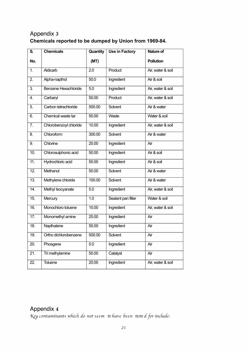
Appendix 3Chemicals reported to be dumped by Union from 1969-84.
S.
No.
Chemicals Quantity
(MT)
Use in Factory Nature of
Pollution
1. Aldicarb 2.0 Product Air, water & soil
2. Alpha-napthol 50.0 Ingredient Air & soil
3. Benzene Hexachloride 5.0 Ingredient Air, water & soil
4. Carbaryl 50.00 Product Air, water & soil
5. Carbon tetrachloride 500.00 Solvent Air & water
6. Chemical waste tar 50.00 Waste Water & soil
7. Chlorobenzoyl chloride 10.00 Ingredient Air, water & soil
8. Chloroform 300.00 Solvent Air & water
9. Chlorine 20.00 Ingredient Air
10. Chlorosulphonic acid 50.00 Ingredient Air & soil
11. Hydrochloric acid 50.00 Ingredient Air & soil
12. Methanol 50.00 Solvent Air & water
13. Methylene chloride 100.00 Solvent Air & water
14. Methyl Isocyanate 5.0 Ingredient Air, water & soil
15. Mercury 1.0 Sealant pan filter Water & soil
16. Monochloro toluene 10.00 Ingredient Air, water & soil
17. Monomethyl amine 25.00 Ingredient Air
18. Napthalene 50.00 Ingredient Air
19. Ortho dichlorobenzene 500.00 Solvent Air
20. Phosgene 5.0 Ingredient Air
21. Tri methylamine 50.00 Catalyst Air
22. Toluene 20.00 Ingredient Air, water & soil
Appendix 4Key contaminants which do not se em t have been tst d for include:
21

- Benzene Hexachloride- Carbon ttachloride- Chemical wast tar- Chlorobenzoyl chloride- Chloroform- Chlorine- Chlorosulphonic acid- Hydrochlroic acid- Meth anol- Metylene chloride- Metyl Isocyanat- Monochloro tluene- Monomet yl amine- Phosgene- Tri meth ylamine
Finaly, in additon t te above, according t te UK (former) Department of Environment, some key contaminants which may be expect d at Pest cide Works include:
Principal matrials relat d t manufactureOrganic solvents (halogenate d)
- dichlorometh ane- etylene dichloride- tifuoroacet c acid- tifuoroet anol- fuorobenzene- carbon ttachloride
Organic solvents (non-halogenate d)- ace to ne- meth anol- dimetyl formamide- aromatc hydrocarbons and derivatves eg benzene, to luene, phenols, pyridine
Organic acids- ace ti c- benzoic
Mineral acids- hydrochloric- sulphuric
Metals, metaloids and teir compounds- arsenic- copper eg copper arsenate s, cupric acetate ,- copper sulphate- chromium- lead eg lead arsenat- manganese- zinc- vanadium (used as a catalyst)- talium (used as a catalyst)
Bases- sodium hydroxide (solid or aqueous soluton)- calcium hydroxide
Typical pest cide groups, common examples and th eir uses
Metalic compounds (inorganic)- copper-chromium-arsenate s, copper salts, mercuric chloride mercuric oxide,
mercurous chloride - used as preservatves, fngicides and antfouling products
Organometall ic compounds- Organotn
tibutl tn oxide1 - used as a wood preservatve and antfouling product
22

- Organic arsenicals organic arsenicals (cacodylic acid – used as a herbicide)
Organophosphorus- dichlorvos, bromophos, diazinon, malath ion – used as insec ti cides
Organochlorine- aldrin, dieldrin, chlordane, DDT - used as insect cides- lindane - used as an insect cide and for vert brat contol
Carbamate s- aldicarb - used as a moluscicide and soil st rilant- aminocarb - used as an insect cide- maneb -used as an insect cide, fngicide and antfouling product
Organonitr ogen compounds- substi tute d ureas
diuron, linuron - used as herbicides- dinitoanilines
tifuralin, 2,4-dinitoaniline - used as herbicide- oth er nitr ogen derivatves
dinitocresol, dinoseb - used as herbicides and insect cides, dinocap - used as a fngicide
- tiazines atazine, simazine, propazine - used as herbicides
Phenoxyacids- 2,4 dichlorophenoxyacet c acid, mecoprop, 2,4,5 tr ichlorophenoxyacet c acid - used
as herbicidesPhenolics
- pentachlorophenol and oth er chlorinatd phenols - used as wood preservatvesMetal carboxylat s
- copper naphtenat , zinc naphtenat - used as wood preservatves and antfouling products
- zinc versatat - used as a wood preservatveQuatrnary ammonium (diphyridils) compounds
- diquat, paraquat - used as herbicidesPyretroids permetrin - used as an insect cide and preservatve
- resmeth rin, bioresmet rin - used as insect cides
Oth ersherbicides benzoic acids, eg:
- chloramben - anilides eg alachlor- chlorinatd aliphatc acids, eg sodium salts of tichloroacet c acid, dalapon (2,2
dichloropropanoic acid)- amines eg picloram- ammonium sulphamat
rodentcides pyriminil- warfarin
moluscicide metal dehyde
Oter pot ntal contaminants
Dioxins Impurites in, for example, organochloride compounds, phenoxyacids, chlorinatd phenols and benzenes, and may result fom combust on of chlorinatd organic compoundsChlorate sCoal tar residuesPolychlorinatd biphenyls (PCBs)Asbes to sFuel oilsCoal and ashEfuent teatment chemicals sodium bisulphat , hydrochloric acid, phosphoric acid - used as pH adjuste rs'Spent' actvatd carbon
23

Full details are available in th e DoE Industr y Profi le for Chemical Works: Pes ti cide Manufacturing Works: htp://www.doeni.gov.uk/SCH00195BJKI-e- e.pdf
24


![03 STI-Aquatest-09-11-12-NGRI[1] [Mode de compatibilité] · trapping of DNA origamis ... 2012, with presentation & discussion on novel bioanalytical detection schemes of special](https://img.pdfslide.us/doc/110x75/601d146b0ae5417a177ea71c/03-sti-aquatest-09-11-12-ngri1-mode-de-compatibilit-trapping-of-dna-origamis.jpg)