Embed Size (px)
Citation preview


TECHNICAL REVIEW No 4 - OCTOBER 1955
CONTENTS: Pago
A new Beat Frequency Oscillator 5
The Automatic Output Regulator of the Beat Frequency Oscillator Type 1014 18
Combined Units 23

We introduce:
A NEW BEAT FREQUENCY OSCILLATOR Type 1014
The Beat Frequency Oscillator Type 1014 is a new design, based on its predecessor Type 1012, and will meet most of the numerous requirements of a signal source for electrical, electro-acoustical and acoustical measurements in modern audio frequency technique. Fig. 1 shows a photo of the Oscillator.
r
Fig. 1. Photo of the Beat Frequency Oscillator, Type 1014.
The physical size and the principle of operation is the same as for the Type 1012. However, important changes are made in the electrical design of the instrument, and new, useful refinements have been added to those which existed in the older model. It is the intention here to describe these new features as well as to give a general description of the instrument.
The Beat Frequency Oscillator Type 1012 and its predecessor Type 1011, have been available on the market since 1949. Due to its design it appeared as a universal instrument for acoustical measurements and during the past years it has become so popular that it can now be found in almost every leading acoustic laboratorv all over the world.
5

However, as the Audio Frequency Spectrometer, Type 2109, was developed and brought onto the market there was a rising demand for a new B. F. O. which was able to synchronize completely with this instrument. Many types of selective measurements could then be performed automatically, and when investigations on electrical equipment are to be carried out on a large scale the advantages of automatic measurements are obvious.
The Beat Frequency Oscillator Type 1014 works on the heterodyne principle using two high frequency oscillators, one of which operates on a fixed frequency, while the frequency of the other can be varied with a variable capacitor.
The required audio frequency is then obtained as the difference between the two high frequencies and can be read off a large, illuminated scale, the pointer of which is connected to the variable capacitor.
Complete synchronization between the Spectrometer and the Oscillator requires that the frequency scale of the Oscillator be logarithmic from Ihe lowest frequencies up to the highest audio frequencies, i.e. a frequency scale according to specifications laid down in U. S. A. This scale will also prove to be advantageous for many types of measurements due to the more accurate scale reading obtained at the lower frequencies. The variable capacitor in the B. F. O. Type 1014 is thus designed to fulfil the requirement of a logarithmic frequency scale.
Fig. 2 shows a block diagram of the complete Oscillator.
Fig. 2. Block Diagram of the Beat Frequency Oscillator, Type 1014.
The fixed oscillator is tuned to 120 kc/s and can be frequency modulated by means of an arrangement as shown in fig. 2. The reactance tube circuit acts as a variable inductance and the modulation swing can be continuously varied from 0 to ± 200 c/s by means of a potentiometer.
0

The frequency modulation is incorporated in order that the acoustical properties of rooms may be studied, such as the reverberation time. When a frequency modulated signal is used for reverberation measurements the possibility of exciting only one of the eigentones of the room and thereby obtain a fluctuating measuring result due to the room resonances, is avoided.
The requirements of an accurate, well defined waveshape of the modulating signal, and the demands for linearity of the frequency modulation itself are not very strict, as long as the energy in the resulting frequency spectrum is approximately equally spaced over a wide frequency band around the center frequency at which the measurements are carried out.
A saw-tooth type of signal is found to give a satisfactory result as modulating voltage, when the frequency swing and modulation frequency are chosen correctly.
It has therefore been found convenient to use a blocking type oscillator, tuned to approx. 5 Mc/s, and the frequency of the saw-tooth oscillations is set by changing the grid resistor.
The following frequencies can be selected by means of a switch: 1—2—4— 8—16 and 32 c/s.
Furthermore, provision is made for external modulation. A voltage of approx. 7 volts is then necessary when a modulation swing of ± 200 c/s is required. To reduce the influence of the blocking oscillator when external modulation is used the impedance of the external generator must be low (Z; - 1 kQ).
As previously mentioned no special precautions have been taken as to obtain a perfect linear modulation. This must be taken into account when the external modulation is to be used for purposes requiring a certain degree of linearity.
A variable capacitor, inserted in the tuned circuit of the fixed oscillator, permits exact frequency selection in the range ± 50 c/s for any setting on the main scale. Thus, using this capacitor, frequencies down to zero may be obtained, even though the main scale is only calibrated from 20 c/s to 20 000 c/s,
Designed to be used with reverberation measurements, a noiseless switch makes it possible to disconnect the supply voltage to the anode of the 120 kc/s oscillator, thereby cutting off the audio frequency voltage delivered to the loudspeaker. The same performance can be obtained by remote control (see fig 2).
The output voltage from the fixed oscillator is fed to the grid circuit of a pentode, the grid bias of which is controlled by means of a regulating amplifier.
To obtain a high degree of regulation the working-point of the pentode is chosen on the non-linear portion of the la - Eg characteristic, near cut-off.
The purpose of this circuit is to control automatically the output power of the Beat-Frequency Oscillator by an A. F.-control voltage; for example, the
7

voltage from a standard microphone placed in the sound field of a loudspeaker which is fed from the Oscillator. In this case the output power of the Oscillator will be controlled so that a constant sound pressure is maintained on the standard microphone.
This regulating equipment, or "compressor" circuit, as it is usually called, also allows the output voltage, or current, from the B. F. O. to be kept constant during measurement, even if the load impedance is changed.
If a constant output voltage is required the output voltage from the Oscillator is used as control voltage. Similarly a constant current is obtained if the voltage drop across a resistor, connected in series with the load, is used as control voltage.
The maximum obtainable range of regulation is 45 db, and different regulation characteristics can be obtained, depending upon the position of the volume control. An example of obtainable regulation curves is shown in fig. 3, together with the measuring arrangement used.
Fig. 3. Regulation characteristics for different positions of the volume control.
The regulating amplifier has a linear frequency characteristic from 30 to 20 000 c/s and should have an input signal of approx. 1 volt on the grid of the A. F. amplifier tube for full regulation. The input impedance is approx. 100 kohms.
A variable potentiometer in the input circuit can be used as volume control for the output power from the Oscillator when the automatic regulation is employed.
8
In the B. F. O. Type 1012 the regulation was dependent upon the peak value of the regulating voltage. This proved to be a disadvantage for some applications where the regulating voltage was not a pure sine wave, and it has been found that a regulation, depending upon the average value was a more appropriate solution of the problems involved in many practical applications of the instrument. To overcome this disadvantage the compressor circuit has been redesigned, and the regulation obtained in Type 1014 is dependent upon the average value of the control voltage.
Furthermore the speed of regulation can be varied. Regulation speeds of 100—200—500 or 1000 db/sec may be chosen by changing the value of the capacitor in the R-C filter network for the rectified control voltage.
An advantage obtained from the possibility of varying the regulation speed is that instability in the regulating system of a measuring set-up may be avoided. A more detailed article deals with this problem. See page 9.
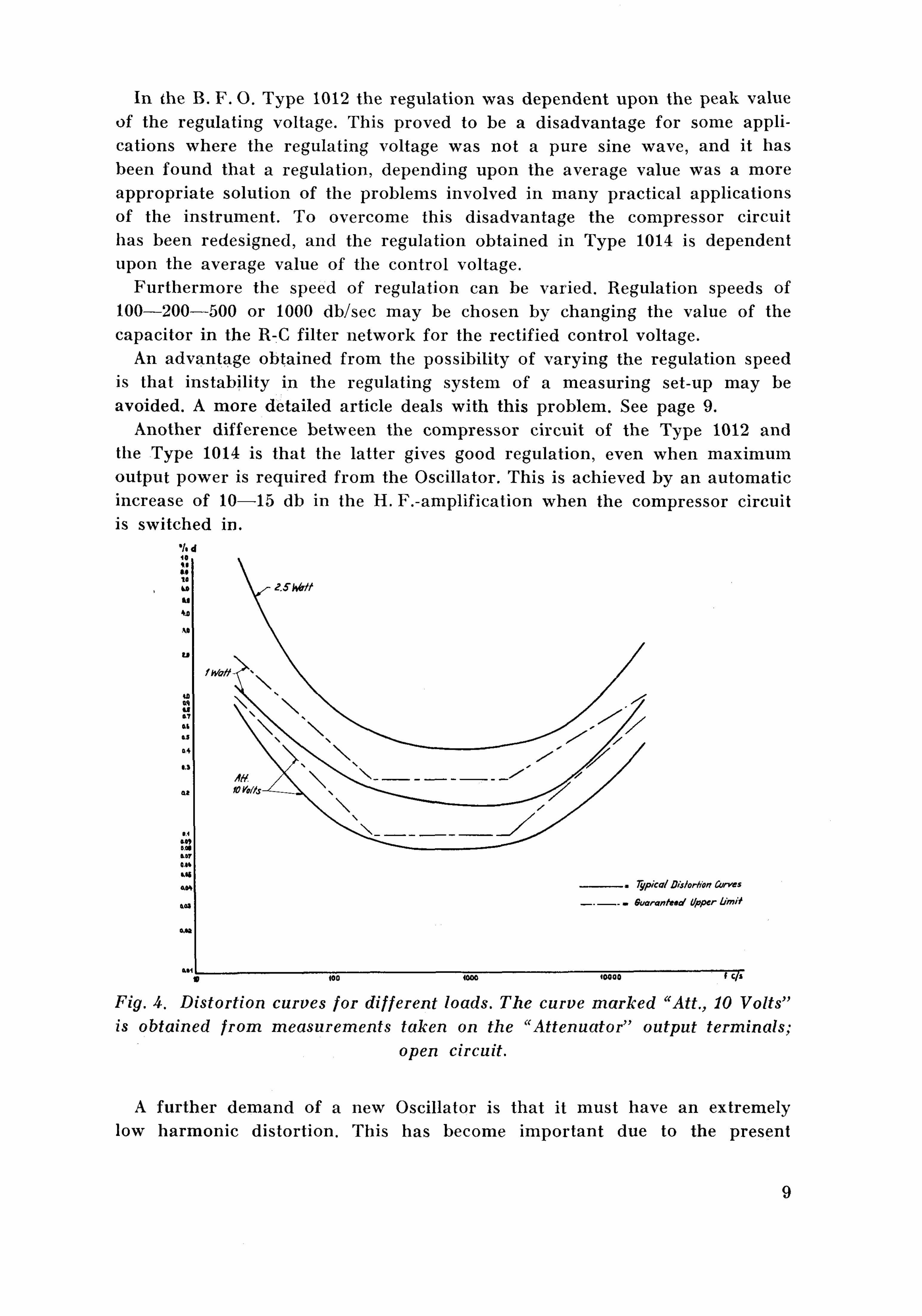
Another difference between the compressor circuit of the Type 1012 and the Type 1014 is that the latter gives good regulation, even when maximum output power is required from the Oscillator. This is achieved by an automatic increase of 10—15 db in the H. F.-amplification when the compressor circuit is switched in.
Fig. A. Distortion curves for different loads. The curve marked "Att., 10 Volts" is obtained from measurements taken on the "Attenuator" output terminals;
open circuit.
A further demand of a new Oscillator is that it must have an extremely low harmonic distortion. This has become important due to the present
9

progress in the high fidelity technique and a special circuit has been introduced, reducing the harmonic distortion to a minimum.
Some typical distortion curves are shown in fig. 4. The distortion is measured on the output terminals of the instrument, for different load values.
To secure a stable operation of the apparatus, and reduce the effect of the electrode capacities of the mixer tube, a neutrodyne stabilization is introduced in the mixer circuit.
In the mixer tube itself, which is one half of a twin triode, the 120 kc/s voltage is mixed with the output voltage from the variable oscillator. The frequency of the variable oscillator can be altered continuously from 120 to 100 kc/s by means of the specially designed variable capacitor. A worm gear. connected to the capacitor spindle, permits automatic tuning with the aid of an external motor, for example the motor in the Level Recorder Type 2304, and the worm gear can be set and released by means of a magnetic clutch.
The introduction of an electro-magnetic clutch is a great advantage as compared with the purely mechanical clutch used in the B. F. O. Type 1012. It is now possible to control the clutch remotely, and synchronization with other apparatus is greatly facilitated.
When the Type 1012 was used for automatic recording an unwanted curve appeared on the frequency calibrated paper for frequencies below 20 c/s and above 20 kc/s. This disadvantage is eliminated in the Type 1014 by short-circuiting the output of the Oscillator in this range.
A further arrangement whereby a particular frequency may be used as a marker, involves the use of the electro-magnetic clutch. This facility is particularly useful when uncalibrated paper is being employed. At the frequency selected the output of the Oscillator is short-circuited, while for all other frequencies the normal output voltage is available.
Basically, the short circuit is effected by closing a pair "of relay .contacts; these contacts are operated by a camdisc which is mounted concentrically on the tuning capacitor spindle. Normally the cam rotates with the spindle, being held in position by a spring-loaded friction clutch.
However, by means of a pawl the camdisc can be located at the point of its cycle where the short-circuiting relay is closed.
Because of the friction clutch, it is now possible to turn the capacitor and the scale pointer relative to, and independent of the cam. Release of the pawl, by means of the control switch, permits the cam to rotate once again with the capacitor.
As previously mentioned the mixer tube is of the triode type, and a low hum level is obtained in spite of the A. C.-heating of the filament. A low-pass filter is inserted in the anode circuit of the mixer tube. The cut-off frequency is 50 kc/s, whereby only the lower sideband, obtained from the frequency conversion, is passed on to the output amplifier. The attenuation of the upper sideband must be rather large due to the effect of the compressor, and is approx. 70 db.
10

The filter is basically the same as the one used in the Type 1012, but ha* been redesigned, and the coils are now wound on ferrox-cube cores, utilizing the low temperature coefficient and the high stability of this core material, as well as its extremely high Q-value.
The voltage from the low-pass filter is fed to the control grid of the first tube in the two-stage audio frequency output amplifier via a variable potentiometer. This potentiometer is used for continuous adjustment of the output power (volume control).
The output amplifier has not been changed from its original design in Type ■t
1012. However, to reduce the harmonic distortion produced in the output tube to a minimum the tube EL41 has been replaced by the new low distortion output tube EL84.
The gain of the amplifier is stabilized by means of negative voltage feedback, and the anode circuit of the output tube is coupled to the impedance matching circuit with the aid of an auto-transformer.
Four different output impedances are available and are indicated by 6, 60, 600 and 6000 ohms respectively.
It should be noted that the output impedance of the Oscillator itself is only approx. 10—20 % of the indicated values, but with correct loading a maximum output power is obtained with a minimum harmonic content.
Fur thermore , correct loading ensures the output voltage to be independent of the frequency to within ± 0.2 db in the range 50 to 10 000 c/s and to within ± 1 db for frequencies between 20 and 20 000 c/s.
A further arrangement makes it possible to connect the output transformer to an attenuator, variable in steps of 10 db from 125 /y.volts to 12.5 volts. The output impedance is constant and approx. 50 ohms. The accuracy of the at tenuator is approx. 2 %.
The voltage on the output terminals is indicated by a vacuum tube voltmeter which measures the average value of the A. F . voltage. It is calibrated in r. m. s. values of a sinusoidal voltage, and the accuracy in the frequency range 20—20 000 c/s is 2 % of full scale deflection.
The sensitivity of the voltmeter is automatically changed when the position of the output switches is altered. Full deflection of the meter is indicated on the switch.
The indicating meter is also used to locate a reference point on the scale. In the Type 1012 zero setting was obtained by adjusting the variable frequency oscillator and the fixed frequency oscillator to have the same frequency when the scale pointer was on zero. Indication was obtained by using a "magic eye" tuning indicator; this method was found to suffer from the fact that with age the screen of the tuning indicator deteriorated. It was therefore decided to use a reference point at the mains frequency and to display the beat between the output voltage and a sample of the mains voltage on the meter.
Before closing this discussion on the Beat Frequency Oscillator Type 1014
11
a few practical remarks on the new refinements introduced might be of r
interest: 1) First of all: A new variable capacitor which provides a completely loga
rithmic scale from 20 to 20 000 c/s is introduced. Advantages: More accurate scale-reading on the lower frequencies. Complete synchronization with the Audio Frequency Spectrometer Type 2109 is possible.
2) Extremely low harmonic distortion. This makes the Oscillator excellently suited as power source when distortion measurements are to be carried out on electronic or electro-acoustic devices.
3) Compressor action dependent on the average value of the regulating signal. That is the output from the Oscillator will not be influenced by sharp, unwanted voltage peaks occurring in the measuring system, and the regulating voltage as measured on a normal A. F. voltmeter will remain constant.
4) Variable speed of regulation. In most cases unstability and self-oscillations in the measuring arrangement can now be avoided.
5) Full output power available, even where the compressor circuit is switched in and in use.
6) No unwanted curves appear on the frequency calibrated paper for frequencies below 20 c/s and above 20 kc/s, when automatic recording of frequency characteristics is carried out.
7) Marking of a certain, prechosen frequency. Advantageous for applications where frequency calibrated paper cannot be used on the Level Recorder, or in other cases where a reference frequency is wanted.
8) Introduction of an electromagnetic clutch for easy synchronization with other instruments when automatic drive of the tuning capacitor is wanted.
9) Introduction of a socket with terminals for remote control. Various forms of remote control are thus possible:
1) Remote control of the magnetic clutch. 2) Remote control of "Oscillator Stop" for reverberation measure
ments. 3) External modulation.
A general description, as given in this text, indicates the main properties of the new Beat Frequency Oscillator. Further information, and examples of its application to normal measuring technique are given in the instruction manual for the instrument.
The applications suggested in the manual are "standard" measurements. However, emphasis has been made to show the "automatic measuring technique" which can be achieved by combining the different instruments obtainable.
V ■ ■ 1 1 i-i ii i i M ■ ■ — ^ ^ ^ » ^ ^ i - » ™ ■ ■ ■ I B M I ■—n r ^
Due to the changes in design, and new refinements introduced in the B. F. O. Type 1014, discussed in this article, it can be seen that reconstruction of already delivered Oscillators of the Type 1012 into a B. F. 0. of Type 1014 will be rather complicated and the factory can therefore not undertake such reconstructions (which must be done separately for each special case).
12

The Automatic Output Regulator of the Beat Frequency Oscillator Type 1014
by Jens T. Broch M. Sc.
For some acoustical applications of the Beat Frequency Oscillator Type 1012 the automatic output regulator employed in this Oscillator has proved to be unsatisfactory. Measuring systems in which a constant sound pressure mas required at a particular point in the sound field from a loudspeaker showed a tendency to instability. When the distance between the emitting sound source (loudspeaker) and the point at which the constant sound pressure was required became large, it was almost impossible to avoid instability. Even with smaller distances between loudspeaker and regulating microphone the possibility of the system becoming unstable was present when a large amount of "compression" was employed.
The automatic output regulator employed in the B. F. O. Type 101A is a completely new design compared with the one employed in Type 1012, and a further control named "Compressor Speed" has been added, providing the possiblity of perfectly stable operation of the regulating system when suitable distances are employed between the loudspeaker and the regulating microphone. At reasonable distances almost any amount of compression can be used without any risk of instability. The function of the new control is double. It provides a certain attenuation of level variations which could otherwise cause instability, and it acts at the same time as a phase regulator. To people familar with the performance of a servo-system this is easily seen. However, a discussion of its functioning will be given in this article, showing the basic properties of the regulating system based on the Nyquist theory of stability.
A measuring system in which automatic regulation of one of the physical quantities involved is employed can be treated by means of the methods used when dealing with ordinary servo-mechanisms.
However, in most practical cases complete mathematical analysis of a servo-mechanism is extremely complicated, and no attempt will be made here to give this type of treatment, because many of the physical principles involved might then be hidden by mathematical approximations.
Fig. 1 shows the basic measuring arrangement, and indicates how this can be transformed into the well-known form of feed-back system as normally treated in electronic amplifier theory.
The variables of the system are: 1) The closed loop amplification. 2) The distance between the emitting source (the loudspeaker) and the
measuring point (the regulating microphone at the point where a constant sound pressure is desired).
13

Starting with the closed loop amplification, this must be kept within certain limits if instability is to be avoided.
Fig. 1. Basic acoustical measuring arrangement, employing the compressor circuit of the B. F. O. The transformation of the arrangement into ordinary
four-terminal network theory is shown.
The mathematical expression for the closed loop amplification can be written: A
A — 1+kA where A is the open loop amplification, i.e. the amplification present when no forms of feed-back is employed in the system.
The most important feature of the above expression is that it is obvious that if the factor k makes the product kA equal to — 1 , an infinite closed loop amplification is present, and the system will start to oscillate, i.e. it is unstable.
To those familiar with electronic amplifier design and/or servo-mechanisms the Nyquist theory of stability is well known. This theory states that if a polar diagram is plotted of the factor kA, as a function of frequency, and the curve includes the point —1 the system will be instable.
There are thus twro factors which determine the stability of a given system: a) The absolute value of kA.
14
b) The phase relationship between the original input quantity and the quantity fed back to the input from the output of the "Black box" called A in fig. 1.
The phase relationship is almost exclusively determined by the measuring set-up (i.e. the distance between the loudspeaker and the regulating microphone). The new B. F. O. Type 1014 includes the possibility for changing this phase relationship slightly. However, a much more important feature of the new regulator employed in Type 1014 is that a variable attenuation of unwanted periodic level changes is incorporated. The adjustment is carried out by changing the R-C-combination in the feed-back (or regulating) amplifier, and is operated by the knob on the front panel marked "Compressor Speed".
The reason for naming this knob "Compressor Speed" is readily seen: If a sudden change in amplitude of the signal fed to the regulating microphone takes place, this change will reach its final value at the output of the regulating amplifier after a certain time delay, due to the R-C-network employed. The "speed" of the correction offered by the feed-back system therefore depends upon the properties of this network, and can be varied in steps from 1000 db/sec to 500 db/sec, 200 db/sec and 100 db/sec, as indicated round the switch.
Now, using the Nyquist method of analyzing a feed-back system, a periodic v
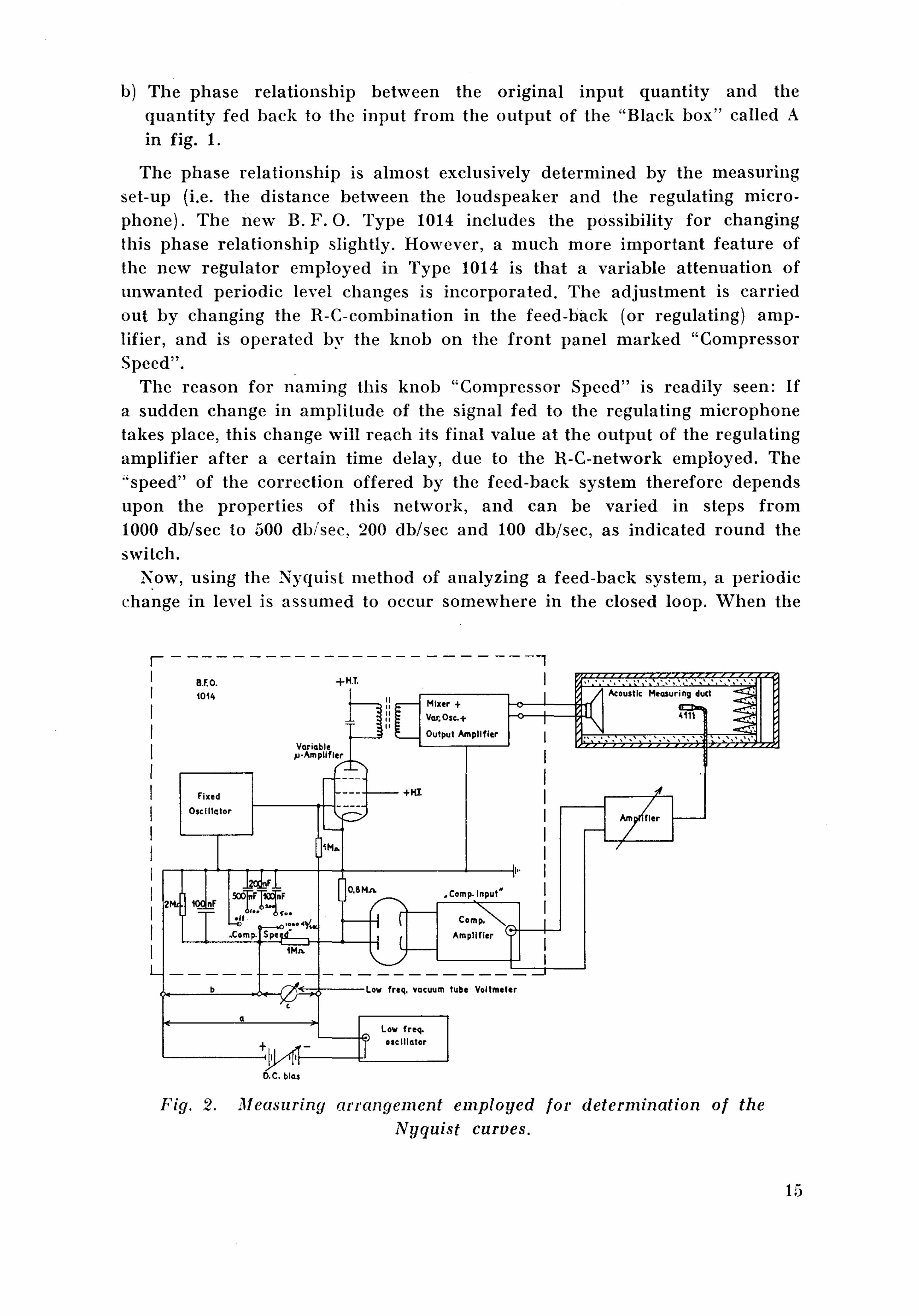
change in level is assumed to occur somewhere in the closed loop. When the
Fig. 2. Measuring arrangement employed for determination of the Nyquist curves.
15
frequency of this level change is varied a polar diagram can be plotted of the output voltage from the feed-back circuit.
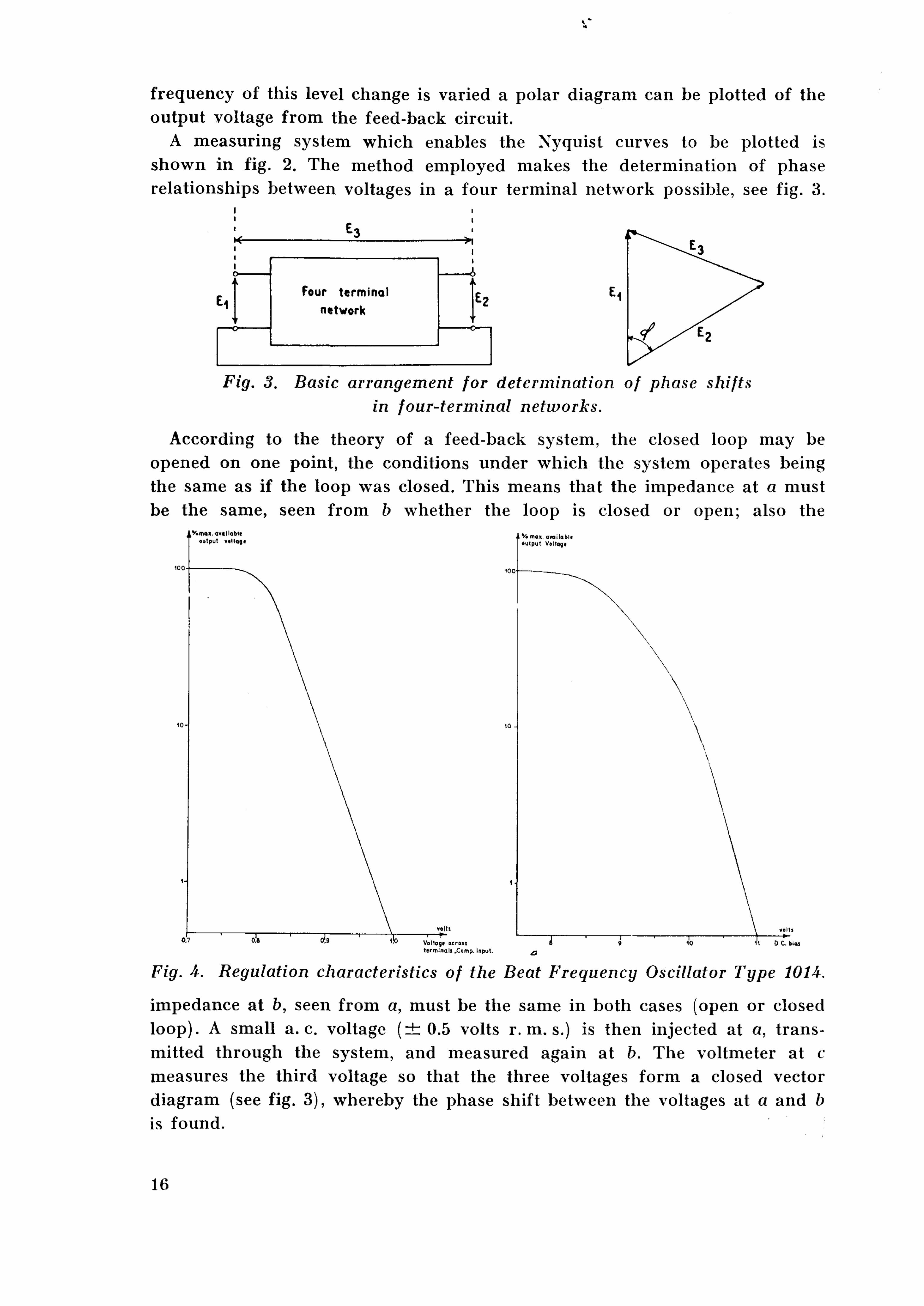
A measuring system which enables the Nyquist curves to be plotted is shown in fig. 2. The method employed makes the determination of phase relationships between voltages in a four terminal network possible, see fig. 3.
Fig. 3. Basic arrangement for determination of phase shifts in four-terminal networks.
According to the theory of a feed-back system, the closed loop may be opened on one point, the conditions under which the system operates being the same as if the loop was closed. This means that the impedance at a must be the same, seen from b whether the loop is closed or open; also the
Fig. A. Regulation characteristics of the Beat Frequency Oscillator Type 1014.
impedance at b, seen from a, must be the same in both cases (open or closed loop). A small a. c. voltage ( ± 0 . 5 volts r. m. s.) is then injected at a, transmitted through the system, and measured again at b. The voltmeter at c measures the third voltage so that the three voltages form a closed vector diagram (see fig. 3), whereby the phase shift between the voltages at a and b is found.
16

By varying the frequency of the voltage injected at a, and measuring the three voltages for each frequency the Nyquist diagram can be plotted. With regard to stability it is seen that the magnitude of the voltage injected at a is of no importance.
However, this value was chosen such that the influence of hum and other disturbing voltages was reduced to a minimum. (The maximum magnitude of disturbing voltages was measured to be 3 mV).
The Nyquist diagram was now plotted for three different, variable conditions. a) When different external amplification was present in the feed-back circuit. b) When the internal attenuation and phase relationship were changed by
means of the knob "Compressor Speed". c) When the distance between loudspeaker and microphone was changed.
Because of the principle of operation of the regulating system, a change of external amplification in the feed-back loop means a change of the working point on the regulating characteristic.
This characteristic is shown in fig. 4a. Fig. 4b shows the relationship
Fig. 5. Nyquist curves for different external amplification in the feed-bak loop.
between the D. C. voltage fed to the regulating tube and the A. C. output voltage from the B. F. O.
17

The curves are plotted with max. output voltage from the Oscillator to equal 100 %. The procedure followed when measuring the Nyquist curves was as follows:
Fig. 6. Nyquist curves for two different positions of the switch "Compressor Speed".
The D. C. working point was chosen, and the corresponding output voltage found from curve 4b. Then, from curve 4a, the correct input voltage to the regulating amplifier (compressor) was found and the system adjusted.
Starting with a) the Nyquist diagram for this case is shown in fig. 5. The different working points as well as the external amplification in the
feed-back loop from the output of the microphone to the terminals marked "Compressor" are indicated in the figure. The position of the knob "Compressor Speed" was "1000 db/sec".
It is seen that for an output voltage of 7 % from the B . F . O. ("Volume r
Control" knob in position max.) the system is unstable, and oscillates, the frequency of the oscillations being approx. 40 c/s.
The "feed-back amplification" was in this case 138 (43 db). (The potentiometer "Compressor voltage" was, of course, in position "max." for all measurements).
18

With an output voltage from the B. F. O. of 30 % the system is perfectly stable.
Fig. 6 shows the Nyquist diagrams for two different positions of the switch "Compressor Speed", the distance Loudspeaker-Microphone, as well as the working point and "feed-back amplification" being indicated on the figure.
It can be seen that a change in the R-C-network of the regulating amplifier in the B. F. O. ("Compressor Speed") has an effect analogous to the one obtained by reducing the "feed-back amplification", which was also to be expected. However, because the d. c. conditions of the regulating tube are not influenced the output from the B. F. 0 . remains constant.
Fig. 7. Nyquist curves for different distances between loudspeaker and regulating microphone. The operating conditions of the system were:
D. C. bias: —10.25 volts. OscilL output: 7% Ext. amplification: A3 db. Compressor Speed: 1000 db/sec.
Fig. 7 shows the effect on the Nyquist diagram when the distance between the loudspeaker and the microphone i? changed.
The frequency at which the system will oscillate is almost exclusively determined by the distance loudspeaker-microphone. This was also to be expected, as the phase shift due to the R-C-network in the feed-back circuit will be small compared with the one obtained from the "travelling wave".
19

The measurements were carried out under approx. free-field acoustical conditions, employing a sound measuring duct terminated by 100 % acoustic absorption for the frequency employed as "carrier" (3000 c/s).
Examining the shape of the Nyquist diagram a little closer the following approximative theory will hold:
If the magnitude of the product kA had been constant throughout the frequency range employed for plotting the curves, the curves would have been circles.
For the system employed the factor A can be considered as constant, as this factor is determined by the acoustic transmission line, i.e.
Px = p0e-ri = p 0 Be- i /n where y = a + j/? and e ~a = B = const.
The factor /? is defined by:
c where c is the velocity with which the sound wave travels, and co is the angular velocity of the periodic level changes.
Then: co co P X
= B p o ( c o s ("cj ') "J" s m ̂ ' ) ) This is the equation of a circle in the complex plane, centered at the origin
Now: p x A = ——^ = const.
p o B
However, the factor k will not be constant throughout the frequency range, which is most easily seen from the effect produced by the R-C-network in the regulating amplifier.
Fig. 5. Basic diagram of the R-C-network employed in the compressor amplifier.
Fig. 8 shows the basic diagram of this ne twork /and a frequency dependent attenuation will be obtained:
1 _
! E i V\ R^);+(0,R"C)
This means that when co —» (X)the radius of the "circle" kA will diminish to zero.
20
The shape of the Nyquist diagram must therefore be a spiral, as proved by the measurements.
The influence of the phase shift obtained by employing the switch «Compressor Speed" can be found from the formula:
o>Rs R C
The double effect of the switch "Compressor Speed" with regard to both attenuation (damping in a regular servo-mechanism) and phase shift is thus obvious.
Before closing the discussion of the automatic output regulator in the new B. F. O. Type 1014 some practical remarks should be added.
The introduction of the switch "Compressor Speed" enables, as previously mentioned, a control of the feed-back system with regard to stability without influencing the D. C. working point of the regulating tube in the B. F. O. Instability in an acoustical measuring system can therefore be avoided without changing the original output level from the Oscillator.
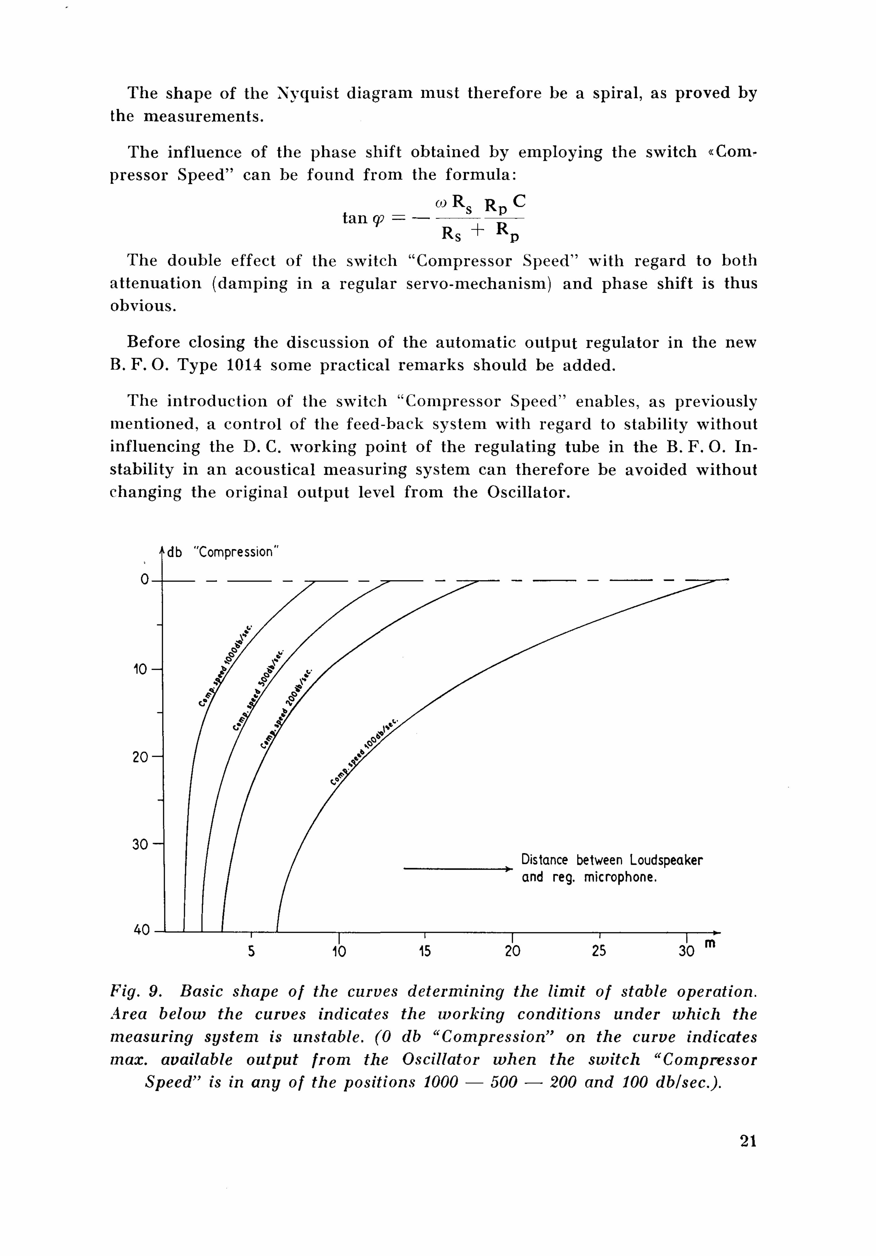
Fig. 9. Basic shape of the curves determining the limit of stable operation. Area below the curves indicates the working conditions under which the measuring system is unstable. (0 db "Compression" on the curve indicates max. available output from the Oscillator when the switch "Compressor
Speed" is in any of the positions 1000 — 500 — 200 and 100 dblsec).
21

4
When the distance between the sound source (loudspeaker) and the regulating microphone is varied the output voltage from the B. F. O. (i.e. the amount of external feed-back) that can be employed without any risk of instability also varies. The basic shape of the curves, showing the limit of stable operation for different positions of the switch "Compressor Speed" is shown in fig. 9. These curves will be true for acoustic free-field conditions, where no reflections of the sound waves take place.
Acknowledgement.
Thanks are due to Professor F. Ingerslev and S. C. Dalsgaard, M. Sc , of the Danish University of Technology, for providing the facilities necessary to obtain the curves shown in fig. 9.
22

Combined Units designed on the basis of the Beat Frequency Oscillator Type 1014
During the past years the automatic measuring technique which can be achieved by mechanically coupling our various instruments has become very popular.
In most cases the motor in the Level Recorder Type 2301 is used as the "driver", and the transmission coupling between the different instruments is carried out by means of flexible shafts.
However, two types of automatic measurements have achieved such popularity that it has been found convenient to place the instruments considered in two combined units, namely the Automatic Frequency Response Recorder and the Audio Frequency Spectrum Recorder.
The Automatic Frequency Response Recorder is a mechanically combined unit consisting of a Beat Frequency Oscillator and a Level Recorder.
Fig. 1. Photo of the Automatic Frequency Response Recorder, Type 3302.
The Unit employing the B. F. 0 . Type 10U and the Level Recorder Type 2304 is shown in fig. 1 and the type number is 3302.
23
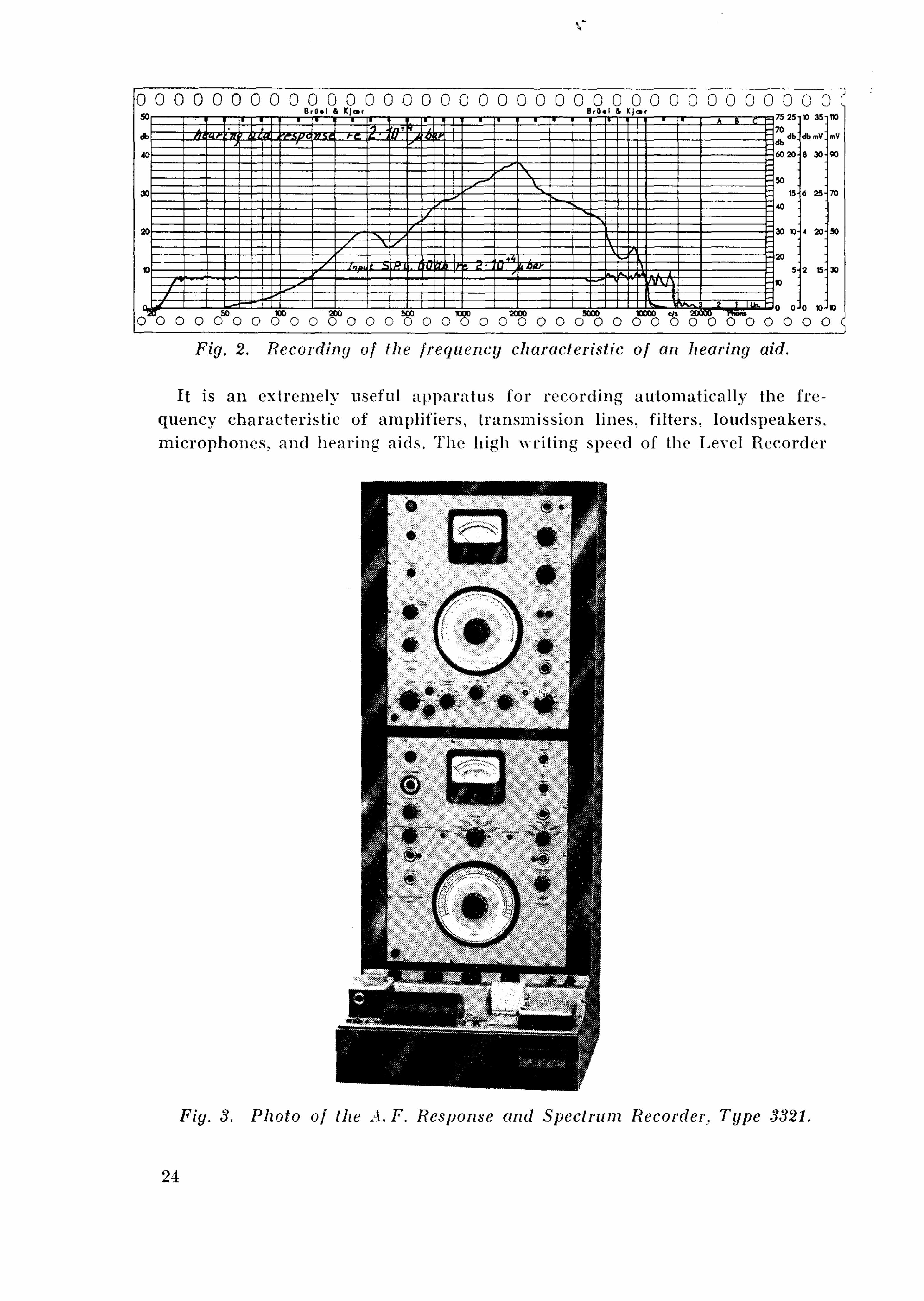
0"0 O O CO O 0"O O 0" o o o o o o "o o o"o o o o"o o o"o o o""o o"""o O O O O C Fig. 2. Recording of the frequency characteristic of an hearing aid.
It is an extremely useful apparatus for recording automatically the frequency characteristic of amplifiers, transmission lines, filters, loudspeakers, microphones, and hearing aids. The high writing speed of the Level Recorder
Fig'. 3. Photo of the A.F. Response and Spectrum Recorder, Type 3321.
24

Fig. 4. Recording of the first, second, third and fourth harmonic produced in an hearing aid.
also makes the equipment well suited to application in electro-acoustical and building acoustical research, e. g. for automatic recording of sound insulation of walls, windows, doors etc. and of reverberation time.
Fig. 2 shows a typical example of a frequency characteristic as obtained from the instrument.
The Audio Frequency Spectrum Recorder Type 2311 is a combined Unit consisting of the Spectrometer Type 2109 and the Level Recorder Type 2304. The instrument is used for automatic analysis of non-sinusoidal voltages, and when employed together with an Oscillator, selective measurements are easily carried out.
Due to the complete synchronization which can be achieved between the Spectrometer and the B. F. O. Type 1014 a third unit is now available: The A. F. Response and Spectrum Recorder, Type 3321. It consists of the B. F. O. Type 1014, the Spectrometer, Type 2109 and the Level Recorder Type 2304, a photo of the instrument is shown in fig. 3.
The field of application is most extensive. Almost any desired measurement in the audio frequency range can be carried out. from the simplest measurement of a. c. voltages to the more complicated automatic recording of harmonics produced in four-terminal networks. Selective measurements can be carried out automatically and registered on the Level Recorder. Combined with a Condenser Microphone Type 4111, noise measurements and analysis are readily performed. It combines all the good properties of the B. F. O., Spectrometer and Level Recorder in one single apparatus and is extremely well suited for laboratory work. When accurate production line tests are required, use of this instrument makes it possible to perform these tests automatically.
The instruments contained in the type 3321 may be used separately or together in various combinations.
25

The synchronization is not made automatic, but the synchronization procedure to be followed is simple.
As previously mentioned, automatic recording of harmonics is possible and an example is shown in fig, 4. A slight change in adjustment must be performed when the third harmonic is recorded. This is described in the instruction manual, and is readily carried out. Up to and including the 5th harmonic can then be automatically measured.
\ \
26