Embed Size (px)
Citation preview

T e c h n ic a l R e p o rt 2 0 14 UiS Subsea, University of Stavanger, Stavanger, Norway
Prepared for:
Marine Advanced Technology Education Centre International Remotely Operated Vehicle Competition 2014
Team members CEO Håkon Kjerkreit CFO Endre Nordahl-Pedersen
CTO Ørjan Mæhre
COO Ola Johansson
Propulsion Design Engineer Lars Ove Frette
Structural Design Engineer Petter Øydegard
Software Design Engineer Stian Sandve
Software Design Engineer Morten Wærsland
Electrical Design Engineer Martin Tienh Trinh
Electrical Design Engineer Erik Sævereid
Electrical Design Engineer Aksel Larsen Rasmussen
Electrical Design Engineer Svein Morten Velde Hauge
Electrical Design Engineer Kristian Sletten
R&D Engineer Sigurd Karolius Holand
Mentors: Rune Rosnes – Oceaneering Jørgen Olsen – Subsea 7 Professor Hirpa G. Lemu – University of Stavanger Professor Morten Tengesdal – University of Stavanger

A b s tr a c t UiS Subsea is a new student team established at the University of Stavanger in the academic
year 2013/2014. We are the first team from Norway to participate in the competition
organized by Marine Advanced Technology Education Center (MATE). The ultimate goal of
the competition is to design and construct a working Remotely Operated Vehicle (ROV),
which has to perform a series of tasks that are different every year. This year’s tasks include
visual inspection, creating photo mosaics and manipulating different locks and levers in the
pool.
The team decided to name our first ROV “Njord”. Njord is designed to perform the intended
tasks in the competition and further to be used at the university for many years to come, and
to serve as platform for research and technology development. The name Njord comes from
the Old Norse god Njörðr, the god associated with sea, seafaring, wind and fishing. This name
was chosen since Stavanger is regarded to be the place where Norway was first unified under
one monarch.
By developing the ROV and participating in the competition, UiS Subsea´s goal is to create
interest for subsea technology and the different challenges related to this field for students at
the University of Stavanger. The students participating in this event will gain valuable
experience in the field of subsea engineering and will be desirable as future employees for
companies in related fields.
This year’s team consists of 14 engineering students from Mechanical, Electrical and Computer Engineering.

Table of Contents Abstract ................................................................................................................................................... 2 Design Rationale ..................................................................................................................................... 4
Planning and Design ............................................................................................................................ 4 ROV Structure ...................................................................................................................................... 6 Buoyancy .............................................................................................................................................. 7 Electronics Housing ............................................................................................................................. 7 Power Regulation ................................................................................................................................. 7 Tether ................................................................................................................................................. 10 Cameras ............................................................................................................................................. 11 Thrusters ............................................................................................................................................ 11 Lights .................................................................................................................................................. 12 Manipulator ....................................................................................................................................... 12 Electrical Systems .............................................................................................................................. 13
Communication .............................................................................................................................. 13 Positioning System ........................................................................................................................ 14 Control System .............................................................................................................................. 15 Power Distrubution .......................................................................................................................... 8 Conductivity sensor ....................................................................................................................... 10
Safety ..................................................................................................................................................... 15 Safety Philosophy ............................................................................................................................... 16
Challenges and Troubleshooting ......................................................................................................... 16 Troubleshooting Techniques ............................................................................................................... 18 Lessons Learned ................................................................................................................................... 18 Reflections ............................................................................................................................................. 19 Future Improvements .......................................................................................................................... 19 Budget .................................................................................................................................................... 20 Acknowledgements ............................................................................................................................... 21 References ............................................................................................................................................. 22 Safety Checklist .................................................................................................................................... 22

D e s ig n R a tio n a le Since UiS Subsea participates in the MATE ROV Competition for the first time this year, preparations were conducted under a very tight schedule. This means that all systems had to be designed from scratch, but with time new team members acquired better experience that enabled us to design more systems simultaneously, resulting in increased complexity of the components to be designed. Stavanger is considered to be one of the cities in the world with the most technical expertise in the field of subsea engineering. This helped us get in touch with several industry mentors. Despite getting some equipment sponsored, our philosophy was to design as much as possible our selves. This can bee seen especially through the design of our thrusters.
Njord the ROV without the manipulator mounted.

Planning and Design The team used the Milestone Summary developed early in the project phase for planning of the entire project. This document stated the deadlines and important milestones of the project, and was useful for the development of the Gantt chart used by the team.
Since the team members had very little experience with designing and constructing ROVs, we started out with an introduction meeting with representatives from Oceaneering. The team started the design process in January 2014 with gathering of possible concepts for the design. The team started with the selection of design concepts in February, as the initial design of the frame was chosen. Most parts of the ROV went through several design revisions. This was especially visible on the design of the frame, since the frame had to be designed to incorporate all parts inside of the structure.
Project Management The team used techniques and techniques from Project Management theories including Work Breakdown Structure, Project Charter and Stakeholder Registers.
Figure 1 Milestone Summary
Concept Selection The team used several techniques for evaluation of ideas and the final concept selection. Since the team participated for the first time, lack of previous experience that could be used as a basis for decision-making. The team started with a brainstorming process for all design concepts. These brainstorming processes were performed with the team divided into a mechanical and electrical branch for organizational effectiveness. This was done so that the team members were able to participate in the concept decisions in the fields where they have their expertise.
Introduction Meeting,
Oceaneering
Team information meeting
Start of Design Phase
Choice of Design Concept
Electronics to be assembled
Start of Testing Phase
Qualification deadline MATE
ROV 2014
Deadline for Manipulator Design
Departure to Competition
nov..13 des..13 jan..14 feb..14 mars.14 apr..14 mai.14 juni.14
Milestone summary UiS Subsea 2014
Figure 2 Concept Selection Process

The two most common decision techniques used by the team was a concept selection process developed by the team (Figure 2) and the use of decision matrixes (Table 1). Feature Make own
thrusters Buy Seabotix thrusters
Bilge pump
Price 6 1 7 Reliability 6 9 2 Time consumption 2 9 5 Impact on engineering report 8 1 4 Total 22 20 19
Table 1 Decision Matrix for Thruster Design
Note: The table gives the evaluation critria and weighting used as a tool in the decision making process for the thruster design
Figure 3 - Thruster Design Development
ROV Structure The design of the frame went through several revisions as more knowledge of the parts that had to fit inside became available. By using HDPE 1000 with a specific density of 940 kg/m3, the buoyancy calculations on the frame became practically negligible since it is approximately the same specific density as water. The structure was waterjet cut from 12mm thick plates by using the CAD-files created in inventor.
Figure 4 ROV Frame Design

Buoyancy Divinycell H80 covered with polyester resin for protection and appearances. The desired shape of the buoyancy was designed with the use of computer aided design (CAD) software, namely AutoCAD Inventor® and machined using a water jet cutter at a local machining company, Smed T. Kristiansen.. The required volume was calculated by inserting the material specifications into the CAD software to calculate the required displacement. Since buoyancy is the weight of the volume of the water displaced, changing the materials in the CAD assembly file to the properties of water, and comparing it to the original calculations could do the calculations.
Figure 5 Buouancy Waterjet Cutting
Electronics Housing All electronics in the ROV is placed in one of three watertight electrical housings. The DC/DC converter gets the tether input, and converts the 48 Volt input to 24V for use in the thruster pod. The end caps are manufactured from solid bolts of aluminum and use several o-rings to prevent water from leaking into the electronics. The thrusters are connected to the electronics housing with the use of subsea connectors donated by Oceaneering.
Figure 6 Thurster Electronics Housing
Power Regulation The DC/DC converter was required since the motors for the thrusters operate on 24V DC, and the supplied voltage from the power source is 48V DC. The team decided to use a single DC converter for all the thrusters since a total of 1000W available for maneuvering is considered to be enough for the current ROV design. The housing for the DC converter is made out of stainless steel, and uses Burton subsea connectors for power in and out. The housing is sealed with the use of a custom-made flat rubber seal.

Figure 7 DC/DC Converter Housing Mechanical Drawing
Power Distribution Power distribution topside As specified in the competition rules, the topside has a fuse box with a 40A fuse. The fuse box also distributes the current over the 8 cords in the power cable.
B-B ( 1 : 5 )
C-C ( 1 : 5 )
B
B
CC
1 A4
Converterbox
DC01State Changes Date Name
Drawn
Checked
Standard
Date Name03.03.2014 Petter Ø
Håkon K
Toleranser i henhold til NS-ISO 2768-m
3,00
132,00
158,00
2,00
P4,00
6x
2,00
373,00
10,00
50,00
52,00
3,00
361,00
148,00
6,3
32,00
32,00
74,0
8P6,00 -7,00 DEEP
31,8
42,231,8 31,8
180,5
353,0010,00
340,00
5,00
Figure 8 Graphical Illustration of the Topside Fusebox

Power Distribution on the ROV On the system there are four different voltages available, 48V, 24V, 12V and 5V. There is a dedicated 24V converter for the thruster system that can supply up to 1000W. There is also a dedicated 5V converter for the electronics. The thruster system has its own converter to prevent variable currents to this system. The electronics system has its own converter to ensure stabile power supply to the STM-cards. All power regulation besides the thruster power is done inside the electronics housing by resistors. The power is then distributed to the components by the use of copper busbars. The power distribution system of the vessel is graphically illustrated in Figure 9. As can be seen in the figure, only one of the thruster motors is drawn in the illustration. There are also some outputs that are not in use at the moment.
Figure 9 Graphical Illustration of the Power Distrubution
Furthermore, as illustrated, all converters, except that of the 24 V, 1000W, are mounted on a card called “Power Unit”. This card is designed by one of the members of the team.
Figure 10 Power Unit Card

Conductivity sensor For the conductivity measurement, we have chosen a conductivity system from Atlas Scientific. It’s going to be an independent sensor with a system connected directly to the computer.
Tether The used tether is supplied by Innova AS, and features standard Burton Subsea Connectors at the ROV end. It consists of one power cable and one signal cable. The tether is expected to suit the needs for the team in many years to come. As a main solution for communication we used fiber optics that have sufficient bandwidth to send both the video feed and communication data from topside to the main node (CCU). This is a fragile solution, which is why we have a backup solution for communication. As a secondary solution for communication we have a multifunction cable that houses a twisted pair and cat5. This made it possible for us to separate the video feed from communication signals.
Figure 11 Testing of Tether with 3 Cameras Connected
The reason why we have two solutions for communication is that if the fiber optics breaks down we don’t have the equipment to fix it which mean that we won´t be able to get it fixed within reasonable time, and in this project time is a critical factor. The power cable consists of four pair of conductors, this means that we can spread the currents and limit the impact of variable currents from the thruster system on the other electronics. Three pairs is used for the thruster system, the last pair supply the rest of the ROV system.

Cameras Three cameras are mounted on the ROV system where two of them are movable in the “y-axis” (vertical). This is designed to improve the visibility of pilots and serve as a tool to help the pilot in the maneuvering. The servomotor mounted on the camera bracket provides this tilting function. The standard web used on the system can produce images up to 1080p, but due to a bottleneck in the available bandwidth at the “BlackBoxes” we can only run them at 720p. The housings are made out of Lexan tubes and POM endcaps. The internal camera bracket is designed in AutoDesk Inventor® and produced by 3D-printing. This made the parts easily modifiable since the design files were saved and available for new prints without much effort.
Thrusters The thrusters used by the team were designed from scratch. By using a pressurized housing with Simmering shaft seals and T-motor MT2826-11 380KV motors. The thrusters run on 24V DC power, and gave each thruster a measured maximum of 428W each. The thruster housings were designed by team members, and manufactured by IKM Technique AS from the design drawings. The thrusters are designed with a pressure compensating rubber plate in the back that keeps the pressure constantly at 50 000 Pa. For deep sea operations the thruster housings are designed to be oil filled, and have been tested in pressure tanks to withstand a pressure corresponding to 4600 meters.
Figure 12 Camera Housing
Figure 13 Thurster Design

Propellers The used propellers are designed by the team and manufactured using a Makerbot 3D-printer. Even though they are not the most durable propellers, the fact that they are cheap and easy to replace made them the most desirable for our use. The team tested several thruster designs, and found that most of the designs delivered a maximum thrust of a maximum of 2.2 kg. Since the difference in the thrust from each propeller design was negligible, the team decided to go with the design that proved to be most durable.
Lights The team designed several different solutions for the lights. After a lot of testing, the team decided to use two different types of lights. This was done due to the power consumed and the expected need for light at different places of the ROV. The lights are manufactured by the team with from an aluminum bolt, and use an o-ring to prevent leakages. LED lights are used due to the low power consumption and heat generated. The aluminum was chosen because of the
high heat conductivity coefficient for the material to lead any excess heat away from the LED light to avoid damage.
Manipulator Design The manipulator allows the ROV to intervene and grab objects and debris on the ocean floor. Njord is equipped with a 3-function manipulator including the gripper. It is designed, manufactured and water sealed by the team. The gripper is 3D printed in ABS and is actuated by a DC motor. The motor is connected to a worm gear system that connects to a set of claws by a hinge-mechanism. One advantage with the worm gear is that it is not back drivable. This ensures that the grippers will not open by it self when holding an object. The wrist joint is actuated by a servo that allows the gripper to rotate 180 degrees. This gives the manipulator an increased versatility when picking up objects. The last joint allows the arm to be lifted up and down and will be helpful in completing the given mission tasks. These two joints is constructed by a combination of 3D printed ABS and water cut HDPE.
Figure 15 Manipulator Arm
Figure 14 Light Housing

Electrical Systems The electrical system is designed by the electrical- and computer -engineers at UiS Subsea. The majority of the electronics is mounted on cards designed by members of this team. Most projects like these use Arduino cards but we have decided to use STM-cards. This is because it is not possible to fully take advantage of the Arduinos processor because of their interface and STM is the platform that is being used at our University.
Communication From topside to the ROV, we have as mentioned earlier two possible solutions, fiber optics or a multifunction cable. If the fiber optics is being used all the data is sent through the fiber between two boxes, where one is topside and the other is mounted on the ROV. On the vessel the signal has to be converted from USB to USART so the STM-cards can read the data. If the secondary solution is being used the data is sent using RS485 and twisted pair. Between the nodes on the ROV the team decided to use RS485 to USART. This secures a stabile communication platform with few errors. Figure 6 shows a graphical illustration of the communication system on the vessel. The fiber optics solution is not drawn in this illustration, but with that solution there is only one communication cable going down to the ROV and it all goes through the BlackBox.
Figure 16 ROV Communication System

Software The topside control system handles joystick inputs and data communication as well as presentation of camera feeds and sensor data to the pilots. The application is written in C# and is based on a three layered architecture (data, logic, presentation). Application flow is described in the flow chart shown below.
Figure 17 Software Flow Charts
Graphical User Interface The graphical user interface (GUI) is spread over two 22” monitors, one for the pilot and one for the co-pilot. Both windows present information about the ROVs state, and a selectable camera feed from one of the three cameras. The layout of the pilot’s window is designed to display only the most important information in a digital manner, while the co-pilot’s window is inspired by analogue instruments used in aviation and includes more details.
Figure 18 Graphical User Interface
Positioning System The dynamic positioning system is used to automatically maintain the ROV´s angular position and heading by using its own thrusters. By using different sensors like an accelerometer, gyroscope and magnetometer, it is possible to obtain information related to the ROV´s angular position. The sensor information allows the system to calculate the required thruster output from each thruster. The dynamic positioning system can also lock the position of the ROV to a fixed distance over the bottom by using an ultrasonic sensor.

Control System Because of the use brushless DC motors for the thrusters, we need motor-controllers for controlling the speed and direction of the motors. The team decided to use motor controllers made for RC, OS OCA-170HV. The motor controllers are placed inside the thruster electronics pod, and is supplied with 24VDC from a single 1000W DC converter. The Thruster Control Unit (TCU) card further controls the motor controller. The TCU-card has a microcontroller, which calculates the thruster-values based on the signals received and sets the pulse-width of the pulse-width signals for each motor controller.
Mussel Counter The team’s Computer Engineers were able to make a program that counts the number of mussels in a picture, and estimates the total number of mussels on the entire ship based on measured dimensions. This program will probably save some time for the team during the mission execution, and help the team be able to perform better on the other tasks.
Figure 20 Mussel Counter Software
Figure 19 Thruster Direction for Different Controller Inputs

S a fe ty Safety Philosophy Our safety philosophy this year is that no task has priority over safety at any time.This led to the implementation of the rule of using safety equipment at any time when operating or using machinery in the workshop. The plug of the electric components was always disconnected before anyone was allowed to start working on them. Mechanical Safety Mechanical safety has been a focus area since day one. Njord has been designed without any sharp edges that could possibly harm divers, personnel or the pool. Covers have been placed on all thrusters to avoid objects from interfering with the propellers, and to avoid potential dangers related to the rotating propellers. Warning labels have been placed on potentially dangerous components of the system. Materials have been chosen that does not harm the operational environment in any way. Electrical Safety The system has separate fuses for each motor and for all outputs from the main power unit. If the system does not receive acceptable data from the topside controller, the system stops all moving parts immediately. Operational Safety UiS Subsea uses a safety checklist every time Njord is in use. This ensures that no unsafe operations are performed, and prevents dangers to both personnel and equipment. When operating the system the team ensures that only the person responsible for tether management is near the poolside. Before lifting the ROV into the water, the mission commander ensures that all personnel keep their hands in safe distance to the thrusters. The mission commander also gives the command for the pilot not to keep clear of the controllers until all personnel are in safe distance from the ROV. Safety Incidents UiS Subsea sustained no major injuries during the project execution. The team had some minor injuries when assembling the thruster from the use of knives while removing old silicone glue on the thruster housings. This led to new safety rules for the team that required the use of protective gloves when using knives.
C h a lle n g e s a n d T ro u b le s h o o tin g Technical When the first testing of the complete system was performed, the picture from the camera revealed some bit errors. The picture below (Figure 4 ?) shows the effect of this error. The team came up with this list of possible reasons for the error:
- Noise from electrical current in the power cable. - Defect camera - Noise on the USB cable in the camera assembly

To identify the reason for the problems, the team replicated the operational environment of the ROV in the laboratory. The identified possible sources of error were then disconnected one at a time, and replaced until the component causing the bit error was found. The problem was found to be the power cable from the servo controlling the tilt function of the camera. This cable was replaced, and for the other cameras the team decided to use the original camera cable all the way to the electrical housing since the shielded cable prevents electrical noise from affecting the signal.
Figure 21 - Camera Bit Error
Interpersonal Challenge The cooperation between different disciplines of engineers was the most difficult interpersonal challenge faced by the team. This includes lack of understanding of what the others needed, and how much space was needed for the different components required. Using weekly team meetings where identified issues were explained for the others and discussed until a working solution was found solved this challenge.

T ro u b le s h o o tin g T e c h n iq u e s Testing Procedures Component testing Alpha testing of components was performed during the early phase of the project. The thrusters were tested in the pressure-testing tank at Oceaneering, and proved to be more than sufficient for sustaining the pressure at the maximum depths Njord will be operating at. Testing of Complete System Testing the complete system was done in the pool at the university. This test started by making sure every component was watertight. As the ROV was placed in the pool, the buoyancy was adjusted until it was almost neutral in the water. When this was done, the team started with testing of the thrusters, and adjusting the vectors in the controller software for the observed effects of joystick inputs.
Figure 22 ROV System Testing
L e s s o n s L e a rn e d Interpersonal Establishing a functioning cooperation between students with backgrounds in different disciplines such as Electrical and Mechanical Engineers can be a challenging task. Different understanding of how things should be done, and what is the most important task can lead to conflicts One major lesson learned through the project is the importance of determining who is responsible for the final implementation when designing two controller systems that are designed to work together. Technical

The other important issue learned in this project is that manufacturing of components takes more time than anticipated. The team suffered some major setbacks on the available testing time compared to the original plan due to critical components requiring a lot more time to manufacture than the team had planned for.
R e fle c tio n s The team feels that through the participation in the competition we have become more motivated students with a better understanding of how engineers work. All members got good training and experience in how to be a part of a bigger team and to work as a unit against a mutual goal. This has been a hectic semester with a lot of late hours at the University, many good memories have been created and a lot has been learnt. “Starting a new underwater robotics team at the University has been an interesting task requiring a lot of hard work and late hours. The contacts gained within the local subsea industry will probably be essential for future employement possibilities, and it seems to me that almost all team members have gained a lot of personal interest for the subsea and will seek future employment in ROV related companies.” Håkon Kjerkreit, CEO
F u tu r e Im p r o v e m e n ts Njord is UiS Subsea’s first attempt to design and build an ROV and there are a number of improvements that have been identified for future versions.
- Use of fluid power: This is to bring up the power to weight ratio on the manipulator. A hydraulic arm would also be easier to design, especially with increased degrees of freedom in mind. Even tough the use of fluid power increases the risks related to any fluid leaks, the team considers the increased power and maneuverability of the manipulator to outweigh these risks.
- Implementation of USB 3.0 system for more sensor capacities and higher camera resolution.
In the communication, there is a bottleneck in the video feed at the BlackBoxes. This is most likely because they don´t support USB 3.0. This prevents us from using all three cameras at the same time at high resolution settings. Limited bandwidth available for cameras is currently not a big problem for the team, but the team regards taking full advantage of the cameras (1080p, they are now running at 720p) would ease the job for the pilot and increase the usefulness of any inspection videos for customers. A way to improve this problem is to implement USB 3.0 or find cameras that support Cat5E (or another high speed system) directly.

B u d g e t Description Expenditures Donated
Electrical
Camera 416,78 Circuit boards 681,46 Conductivity sensor 231,78 Connectors 6711,41 DC/DC converter 529,55 Laser 87,47 Electrical components 2297,45 Lightning 227,85 Tether 75,09 Thrusters 3164,85 Power supply 4194,63
Mechanical
Buoyancy 838,93 Gears 162,42 Machineing 7500,00 Materials 1161,53 335,57 Tools 870,61 Tubing 208,27 Seals 1234,56 Screws and bolts 460,49
Computer Computer and monitors 1257,21
Computer cables 88,59 Joystick 68,46 USB/USB hub and extender 743,16
Other
Banking and card fee 33,72 Competition course 617,95 Miscellaneous 257,61 Office supplies 33,17 Shipping/customs/VAT 847,65 Website 14,60 Welfare (Coffee, pizza etc.) 496,05 Car rental 963,42 Accommodation 7634,23 Airline tickets 20419,46
Total NOK/USD exchange rate 5,96 49480,09 15385,91 Total income: Income sponsors 48657,72 15385,91 Student contribution 822,37

A c k n o w le d g e m e n ts MATE Center for hosting the competition. The University of Stavanger – Provides funds, materials and laboratory spaces. Oceaneering – Provides funds, subsea connectors and technical expertise Subsea 7 - Provides funds and technical expertise Innova AS - Provides funds, subsea connectors and technical expertise IKM Subsea – Provides funds Kongsberg Maritime – Provides funds Smed T. Kristiansen AS – Waterjet cutting of components IKM Technique AS– Manufacturing of thurster housing RTS AS – Providing us with fiberoptics Lie CNC AS – Manufacturing of components Depro AS – Manufacturing of components Envirex AS – Manufacturing of components Mundal Subsea AS – Provides Divinycell H80 for buoyancy. Professor Arnfinn Nergård, Professor Hirpa G. Lemu and Professor Morten Tengesdal for providing us with technical expertise and advice during the development of our ROV.

R e fe re n c e s Christ, R. D., & Wernli, R. L. (2011). The ROV Manual. Waltham: Butterworth-Heinemann. Moore, S. W., Bohm, H., & Jensen, V. (2010). Underwater Robotics Science, Design and Fabrication. Monterey: MATE.
A p p e n d ix e s
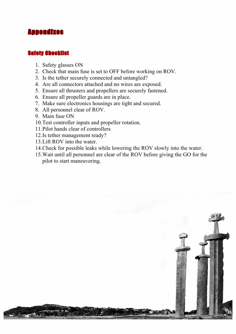
Safety Checklist
1. Safety glasses ON 2. Check that main fuse is set to OFF before working on ROV. 3. Is the tether securely connected and untangled? 4. Are all connectors attached and no wires are exposed. 5. Ensure all thrusters and propellers are securely fastened. 6. Ensure all propeller guards are in place. 7. Make sure electronics housings are tight and secured. 8. All personnel clear of ROV. 9. Main fuse ON 10. Test controller inputs and propeller rotation. 11. Pilot hands clear of controllers 12. Is tether management ready? 13. Lift ROV into the water. 14. Check for possible leaks while lowering the ROV slowly into the water. 15. Wait until all personnel are clear of the ROV before giving the GO for the
pilot to start maneuvering.

System Interconnection Diagram Communication
11
22
33
44
55
AA
BB
CC
Date: 18 m
ay 2014KiC
ad E.D.A.
Rev:
Size: A4Id: 1/1
Title: noname.sch
File: Oversikt com
.schSheet: /
Out
PilotJO
YSTICK
Out
Co-pilot
JOYSTIC
K
Out
Co-pilot
JOYSTIC
K
in in in
outout
TOPSID
E_CO
MPU
TER
inout
BLACKBO
X
inout
UM
R232R
in
MCUPCU
TCU
2xLi4xLi
2xAuServ
CC
U
inSonaLasePres
PCU
in5xmo
MC
U
in7MC
TCU
in
USB
USB
USB
USB
BLACKBO
X_RO
V
Sonar
Laser
Pressure
5xMotor
7xMotor
Camera
Camera
Camera
4xLights
2xLights
2xServo_camera
Twisted pair
Cat5E
RS485R
S485
RS485
PWM
PWM
PWM
TopsideR
OV
RS485
1
Com
ments:
1 - Aux is two extra servo outputs.
2 - Fiberoptics is also an alternative. This makes no changes w
hen the fiber also goes between tw
o "BlackBoxes"
2

System Interconnection Diagram Electrical
11
22
33
44
55
AA
BB
CC
Date: 18 m
ay 2014KiC
ad E.D.A.
Rev:
Size: A4Id: 1/1
Title:
File: Oversikt strøm
.schSheet: /
+1
+2
+3
+4
-5
-6
-7
-8
+in
-in
START_W
IRE
+1
-2
MAIN
_POW
ER
12
40A
FUSE
+ in
+ in
+ in
- in
- in
- in
+out
+out
+out
-out
-out
-out
SD-1000L-24
+ in
+ in
+ in
+out
+out
+out
+out
+out
+out
+out
24V_BUS
- in
- in
- in
-out
-out
-out
-out
-out
-out
-out
24V_BUS_G
ND
+ in- in
1out2out3out
MC
_THR
USTER
in 1
in 2
in 3
MO
TOR
1 2FUSE
48V+48V-
Aux 12V+Aux 12V-
Aux 24V+Aux 24V-
Aux 5V+Aux 5V-
BlackBox 5V+BlackBox 5V-
CC
U 5V+
CC
U 5V-
Light 12V+Light 12V-
Light 24V+Light 24V-
Manip 12V+
Manip 12V-
Manip 24V+
Manip 24V-
Manip 5V+
Manip 5V-
PCU
5V+PC
U 5V-
TCU
5V+TC
U 5V-
1
1 1 1 1 1 1 1 1 1 1 1 12
2 2 2 2 2 2 2 2 2 2 2 2
POW
ER_U
NIT
12
24V
Motor
12
12V
Motor
12
24V
2xLights
12
12V
4xLights
12
5V
BlackBox
12
5V
TCU
12
3V
Laser
12
5V
Sonar
12
5V
Pressure
12
34
PCU
12
5V
CCU
12
5V
MCU
48VDC
24VDC
48VDC
48VDC
/40A
1
Com
ents:1 - All seven m
otors are connected in the same w
ay. Only show
ing one in this schematic for better overview
.2 - Aux are extra outputs. 3 - All outputs on this card has a fuse, see ow
n schematic
2222
3
Topside
RO
V