Embed Size (px)
Citation preview

NIPPON STEEL & SUMITOMO METAL TECHNICAL REPORT No. 113 DECEMBER 2016
- 34 -
1. IntroductionSteel pipe piles, which have applicability to a large variety of
construction methods and types of ground, have been applied suc-cessfully to a number of foundation structures to date in the fields of bridges, harbors, and buildings. In particular, steel pipe piles exhibit excellent performance in terms of satisfying demand for shortening of the construction period as well as work with long piles, in com-parison with work with cast-in-place piles that require the placement of concrete on-site. Since steel pipes are manufactured in a factory and are then transported to a construction site for use as piles, these products are subject to a restriction on land area transportation that limits the length of a steel pipe pile to just over 10 m. For this rea-son, during construction work, the required pile length has to be ob-tained by jointing piles at the site. In recent situations in which there has been an increase in demand for reinforcement and renewal of infrastructures, cases where the work space is narrowed by existing structures around or above the site or where a stringent restriction on overhead space is imposed are increasing. Under such circum-stances where short-length steel pipes are frequently being used, de-mand for jointing many piles is especially increasing.
Self-shielded arc welding is used as a steel pipe pile jointing method at construction sites. Such work is performed by highly skilled welders, and the quality is strictly managed under appropri-ate conditions. However, there are numerous restrictions in joint welding. For instance, it is impossible to perform joint welding work under poor weather conditions or at a construction site that prohibits the use of fire. Furthermore, a scarcity of well-experienced
welders has become a problem in recent years. From this, demand to make the quality control of on-site welding stricter is growing as well. Against this backdrop, mechanical joints have been emerging in lieu of welded joints as a means of realizing enhancement of effi-ciency in on-site jointing work for steel pipe piles.
Nippon Steel & Sumitomo Metal Corporation has responded to these social demands so far by providing the Laqnican™ joint 1, 2) and the Hi-SHJ ™ (Hi-Shake Hand Joint).3) (the Hi-SHJ is a regis-tered trademark owned by Shintoku Kogyo Co., Ltd.). However, progress has been made in recent years in increasing the diameter, thickness, and strength of steel pipe piles themselves with the aim of rationalizing structures, leading to an increase in the application scope. Along with this, demand for simplification of on-site quality control, as well as demand for mechanical joints for further rational-ized use, is arising. In parallel with this trend, there is a strong desire for structural rationalization of the joints themselves. Reported in this paper are the features and performances of the Gachi-cam Joint ™, a new mechanical joint that has been developed in response to these demands.
2. Gachi-cam Joint —A New-model Mechanical Joint2.1 Outline of Gachi-cam Joint
An outline of the structure of the Gachi-cam Joint is shown in Fig. 1 and Photo 1. The Gachi-cam Joint is composed of a pin joint (on the inner pipe side of the joint), a box joint (on the outer pipe side of the joint), and an anti-rotation member. The pin joint and box joint have four gears each at an outer surface and an inner surface,
Technical Report UDC 624 . 154 . 7
* Senior Researcher, Steel Structures Research Lab., Steel Research Laboratories 20-1 Shintomi, Futtsu City, Chiba Pref. 293-8511
Development of the Mechanical “Gachi-cam Joint™” for Steel Pipe Piles and Steel Pipe Sheet Piles
Masashi KITAHAMA* Yoshiro ISHIHAMAHironobu MATSUMIYA Yoshinori FUJIIToshihiko SAKAMOTO Shinji TAENAKATadachika MOCHIZUKI Hiroyuki TANAKA
AbstractThe mechanical joint for steel pipe pile and steel pipe sheet pile is increasingly adapted
to the project of the reinforcement and renewal infrastructure instead of conventionally welded joints, because these projects require rapid construction, early-service and low alti-tude head construction condition. Because of these situations, authors have developed on the new mechanical joint “Gachi-cam Joint ™” with higher rationality and coverage.

NIPPON STEEL & SUMITOMO METAL TECHNICAL REPORT No. 113 DECEMBER 2016
- 35 -
respectively, and their structure is designed to transmit loads with these gears engaged with each other. The pin joint and box joint are already welded to a steel pipe in advance in a factory, and jointing work at a construction site will be completed by rotating the pin joint after inserting a pin joint gear into a circumferential direction groove of the box joint, followed by fixing the anti-rotation member to the joint part. The anti-rotation member is attached in order to prevent gear engagement from releasing due to relative rotation of the pin joint and box joint during the piling work. The joints are made as thin as possible using high-tensile steel of 880 N/mm2 class in tensile strength.2.2 Features of Gachi-cam Joint
The Laqnican joint has acquired a construction technology re-view and examination certificate 1) in the field of civil engineering and confirmatory examination, evaluation on private technologies for port and harbor construction 2) in the field of harbors, and the Hi-SHJ has acquired a certification 3) in the architectural field. A com-parison of Nippon Steel & Sumitomo Metal's mechanical joints is shown in Table 1. As its main structural members, the Laqnican joint uses a joint body, along with load-transmitting keys and set bolts that are made from materials different from those of the joint body. Therefore, this joint requires many parts and multiple types of steel materials, making the joint thick as a whole. For this reason, its
steel weight becomes heavier than that of other joints such as the Hi-SHJ, and the quality control burden regarding material quality, dimensions, etc. is relatively high, taking a longer time for delivery depending on the conditions.
Although the number of parts used in the Hi-SHJ is smaller than that used in the Laqnican joint as the Hi-SHJ transmits loads using the gears of the joint body, the range of the applicable diameter and plate thickness is relatively narrow. Moreover, the applicability of both the Laqnican joint and the Hi-SHJ to a high-strength steel pipe of SM570, etc. has not yet been confirmed. While adoption of high-strength steel pipes is increasingly considered from the standpoint of design load increase, sophistication of performance demanded, etc., the application of mechanical joints is particularly desired as higher-level execution management is required for in-situ welding of high-strength steel pipes. In this context, the development of me-chanical joints that are easy to manufacture and whose quality is easy to control, and also that excel in applicability, has been desired. The Gachi-cam Joint developed in response to these demands has the following features.(i) Gears that are integrated with the joint form a mechanism that
transmits loads when used, and its structural members consist only of a pin joint and box joint that are made from the same material. The small number of parts and part types used facili-tate quality control.
(ii) The scope of application includes steel pipes of 400–1 600 mm in diameter, and 6–30 mm in thickness. SM570 has been in-
Table 1 Comparison of mechanical joint
Name Gachi-cam Joint Laqnican Joint Hi-SHJ
Figure
Structural parts Joint with gear Joint and load transmission key Joint with gear
Applicable specification of steel pipe pile
Material: SKK400, SKK490, SM570Diameter: 400–1 600 mmThickness: 6–30 mm
Material: SKK400, SKK490Diameter: 400–1 600 mmThickness: 9–30 mm
Material: SKK400, SKK490Diameter: 400–1 200 mmThickness: 9–22 mm
Fig. 1 Shape of Gachi-cam Joint Photo 1 Photos of Gachi-cam Joint
NIPPON STEEL & SUMITOMO METAL TECHNICAL REPORT No. 113 DECEMBER 2016
- 36 -
cluded in the applicable materials in addition to SKK400, SKK490, etc.
(iii) The Gachi-cam Joint has a structure in which gears disperse loads when transmitting, and the larger the number of gears, the smaller the gear dimensions required for each gear, allow-ing a reduction in joint thickness. In addition, the Gachi-cam Joint has a tapered shape in which the plate in the part near the joint tip is made thin and the plate becomes thicker toward the foot of the joint, reducing the load shared by gears as the load approaches the joint tip. A four-step taper is employed for the joint as it has the best balance between the amount of machin-ing and section dimension, and thus the joint has a rational structure with a compact shape.
(iv) The joint has a structure in which gears equally divided in the circumferential direction engage with each other, and jointing work is easily completed only by rotating the joint just a few centimeters that corresponds to the width of one gear.
(v) It is possible to confirm that the gears of the pin joint and box joint are completely engaged with each other at a predeter-mined position by attaching an anti-rotation member after ro-tating the gears. This facilitates execution management.
3. Structural Performance of Mechanical Gachi-cam JointThe structural specifications of the Gachi-cam Joint are deter-
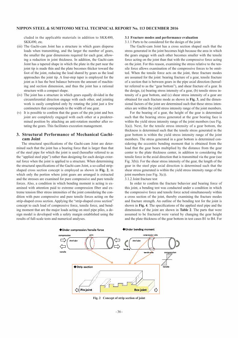
mined such that the joint has a bearing force that is larger than that of the steel pipe for which the joint is used (hereafter referred to as the “applied steel pipe”) rather than designing for each design exter-nal force when the joint is applied to a structure. When determining the structural specifications of the Gachi-cam Joint, a so-called strip-shaped cross section concept is employed as shown in Fig. 2, in which only the portion where joint gears are arranged is extracted and the stresses are examined for pure compressive and pure tensile forces. Also, a condition in which bending moment is acting is ex-amined with attention paid to extreme compression fiber and ex-treme tension fiber stress intensities of the joint considering the con-dition with pure compressive and pure tensile forces acting on the strip-shaped cross section. Applying the “strip-shaped cross section” concept to each load of compressive force, tensile force, and bend-ing moment that are the major loads acting on steel pipe piles, a de-sign model is developed with a safety margin established using the results of full-scale tests and numerical analyses.
3.1 Fracture modes and performance evaluation3.1.1 Parts to be considered for the design of the joint
The Gachi-cam Joint has a cross section shaped such that the stress generated in the joint becomes high because the area in which the gears engage with each other becomes smaller with the tensile force acting on the joint than that with the compressive force acting on the joint. For this reason, examining the stress relative to the ten-sile force allows examination of the compressive forces to be omit-ted. When the tensile force acts on the joint, three fracture modes are assumed for the joint: bearing fracture of a gear, tensile fracture of a section that is between gears in the pipe axial direction (hereaf-ter referred to as the “gear bottom”), and shear fracture of a gear. In the design, (a) bearing stress intensity of a gear, (b) tensile stress in-tensity of a gear bottom, and (c) shear stress intensity of a gear are obtained for each fracture mode as shown in Fig. 3, and the dimen-sional factors of the joint are determined such that these stress inten-sities are within the yield stress intensity range of the joint members.
For the bearing of a gear, the height of the gear is determined such that the bearing stress generated at the gear bearing face is within the yield stress intensity range of the joint members (see Fig. 3(a)). Next, for the tensile stress intensity of a gear bottom, the thickness is determined such that the tensile stress generated in the gear bottom is within the yield stress intensity range of the joint members. The stress generated in a gear bottom is determined con-sidering the eccentric bending moment that is obtained from the load that the gear bears multiplied by the distance from the gear center to the plate thickness center, in addition to considering the tensile force in the axial direction that is transmitted via the gear (see Fig. 3(b)). For the shear stress intensity of the gear, the length of the gear in the steel pipe axial direction is determined such that the shear stress generated is within the yield stress intensity range of the joint members (see Fig. 3(c)).3.1.2 Joint fracture test
In order to confirm the fracture behavior and bearing force of this joint, a bending test was conducted under a condition in which the compressive force and tensile force acted simultaneously within a cross section of the joint, thereby examining the fracture modes and fracture strength. An outline of the bending test for the joint is shown in Fig. 4. The specifications of the applied steel pipe and the dimensions of the joint are shown in Table 2. The parts that were assumed to be fractured were varied by changing the gear height and the plate thickness of the gear bottom in test cases B1 to B4. For
Fig. 2 Concept of strip section of joint

NIPPON STEEL & SUMITOMO METAL TECHNICAL REPORT No. 113 DECEMBER 2016
- 37 -
the shearing of the gear, considering the influence of bending shear-ing, etc., an ample margin is secured in the actual product specifica-tions by specifying the provisions for the dimensions in which the gear length in the steel pipe axial direction shall be twice the gear height. The state of fracture is shown in Fig. 5, while a summary of the test results is shown in Figs. 6 and 7, and it was confirmed that the fracture occurred on the extreme tension fiber side of the joint in all cases. The plotted test results shown in these figures indicate the maximum bending moment in this test, and these values are those when the fracture occurs. The dotted line in Fig. 6 represents the computational bearing strength of the joint when the bearing stress of the gear reaches the yield stress intensity of the joint material,
while the chain line indicates the limiting values for separation. The dotted line in Fig. 7 represents the computational bending strength of the joint when the tensile stress of the gear bottom reaches the yield strength intensity of the joint material.
Table 2 Specifications and targets of steel pipe pile
CaseSpecifications of joint
applied steel pipeHeight of gear
(mm)
Thickness between gears
(mm)B-1 SKK400 φ 800 × t 5 mm 2.4 6.6B-2 SKK400 φ 800 × t 9 mm 3.3 6.9B-3 SKK400 φ 800 × t 9 mm 4.2 7.2B-4 SKK400 φ 800 × t 13 mm 4.2 9.5
Fig. 7 Result of bending test (B-2, 3, 4)Fig. 4 Bending test (Case B-4)
Fig. 5 Failure mode of bending test
Fig. 6 Result of bending test (B-1, 2, 4)
Fig. 3 Verification item of joint

NIPPON STEEL & SUMITOMO METAL TECHNICAL REPORT No. 113 DECEMBER 2016
- 38 -
In B-1 where the gear height was lowered most, the maximum bearing force is determined by the separation fracture in which the gear engagement was released due to the elastic deformation of the joint. Although the computational bending strength of the joint that was determined by the bearing stress of the gear was higher than the above maximum strength, the actual product specifications are pro-vided with the lower limit in gear height as shown in the dotted line in Fig. 6, in order to avoid a phenomenon in which the engagement itself is released abruptly. In B-2, the maximum strength was deter-mined by the bearing fracture of the gear, while in B-3, the maxi-mum strength was determined by the tensile fracture at the gear bot-tom. Moreover, in B-4, the bearing fracture of the gear and the ten-sile fracture at the gear bottom occurred approximately at the same time. In Fig. 6, the maximum strengths in B-1, B-2, and B-4 are po-sitioned on the upper side of the straight line formed by the compu-tational values of the bending strength of the joint that is determined from the bearing stress of the gear, while in Fig. 7, the maximum strengths in B-3 and B-4 are positioned on the upper side of a straight line established by the computational values of the bending strength of the joint that is determined from the tensile stress of the gear bottom.
The above results experimentally confirmed that the fractures of the Gachi-cam Joint occurred in the modes that had been assumed in advance, and that the strengths were higher than those computa-tionally assumed. Furthermore, highly accurate design method had been developed by reflecting these results.3.2 Verification of performance by bending tests
Bending tests had been conducted in order to confirm that the bearing force of the joint for which specifications were determined according to the above-mentioned design method for the applied steel pipe was equal to or higher than the bearing force of steel pipes actually used. The specifications of the steel pipes to which the joint tested was applied are shown in Table 3. Test cases were set in order to include the minimum and maximum diameters as well as the minimum and maximum plate thicknesses within the scope of appli-cation. The test results confirm that the joint has a bending strength higher than that of these steel pipe bodies. The main test results are described as follows.
An image of the site of the bending tests for the joint is shown in Photo 2. In the one-directional bending test, the load was gradually increased in a pulsating manner. An example of the one-directional bending test results is shown in Fig. 8. After the steel pipe had reached its full plastic bending strength, no damage occurred in the joint in spite of a gradual decrease in the increasing amount of the load with an increase in displacement, which was caused by plasti-cization of the steel pipe, and, eventually the maximum load was
determined by the occurrence of local deformation that was generat-ed in the steel pipe in the vicinity of a loading point. The deformed spot is shown in Photo 3. The maximum load observed was 1.8 times the yield bending strength of the steel pipe, and 1.3 times the full plastic bending strength of the steel pipe.
In each test case in the one-directional bending test, it was con-firmed that the bending strength of the joint surpassed that of the steel pipe body when the load is applied up to the full plastic bend-ing strength of the steel pipe. In addition, it was confirmed in each case using the test pieces with “*” in Table 3 including the cases
Table 3 Bending test of steel pipe pile with Joint
Test type Specifications of joint applied steel pipe pile
Monotonic four-point bending test
SKK400 φ 400 × t 6 mm*SKK400 φ 800 × t 9 mmSKK490 φ 800 × t 16 mm*SKK490 φ 800 × t 24 mmSM570 φ 1 200 × t 19 mmSKK490 φ 1 219.2 × t 30 mmSKK400 φ 1 600 × t 19 mm*SKK490 φ 1 600 × t 25 mm
Cyclic bending test SKK490 φ 800 × t 16 mm
Photo 2 Photo of bending test (φ 1 600 × t 19 mm)
Fig. 8 Result of bending test (φ 1 600 × t 19 mm)
Photo 3 Photos of local deformation

NIPPON STEEL & SUMITOMO METAL TECHNICAL REPORT No. 113 DECEMBER 2016
- 39 -
shown in Fig. 8 that the bending strength of the joint surpassed the maximum bending strength of the steel pipe under a condition in which loading was continued until the load exceeds the full plastic bending strength of the applied steel pipe, causing the steel pipe to locally deform to reduce the load.
Moreover, in an alternating loading test, load was applied multi-ple times each in the positive and negative directions up to the yield bending strength and full plastic bending strength of each steel pipe. As a result, resistant performance was exhibited on both positive and negative sides approximately equivalent to the behaviors ob-served in the one-directional bending test, thus demonstrating that the joint was capable of sufficiently resisting even repeatedly acting loads such as inertial force applied at the time of earthquake.
The above results confirm that the use of steel pipes with the joint is possible even under extremely severe conditions that cause plasticizing in steel pipes such as a massive earthquake.3.3 Verification of performance by compression and tension tests
Figure 9 shows an outline of the compression test and tension test for the joint, and Fig. 10 shows the results of these tests. The strain values were obtained using strain gauges attached to the posi-tions in the axial direction shown in the joint cross-sectional views in Fig. 10. The test piece used was a half-scale model of the joint with specifications applicable to pipes of a typical size of 800 mm in diameter and 12 mm in thickness. The strain generated at the joint was elastic up to a load that was equivalent to the yield compressive strength and yield tensile strength of the steel pipe, thereby confirm-ing that the Gachi-cam Joint possesses a compressive strength and tensile strength that are equal to or higher than those of the steel pipe body.
4. Performance for Workability4.1 Workability of jointing
In order to demonstrate that this joint allows for simple and short-time jointing work, a construction test was conducted using a full-scale steel pipe pile. The test piece was composed of a steel pipe of 1 000 mm in diameter and 10 mm in thickness with the joint at-tached, and jointing work of the Gachi-cam Joint was carried out af-ter an upper pile was assembled using a crane on a vertically fixed lower pile. Photo 4 shows work at the test site and Table 4 shows the jointing test results. The entire jointing work from the position alignment of the steel pipe with the joint attached to the end of the work including the removal of the rotation tool took less than four minutes. The results confirm that the jointing work can be per-formed in a short period of time.4.2 Applicability to hammer and vibration driving methods
In the hammer driving method and the vibro-hammer driving method, it is inevitable that joints are subject to repeated impacting loads during the work. In order to confirm the applicability of the Gachi-cam Joint to these construction methods, the driving test shown in Photo 5 was implemented. The steel pipe pile used was a pile of 800 mm in diameter and 17 mm in thickness, and the Gachi-cam Joint was arranged in the junction area where a 4-m-long upper pile and a 16-m-long lower pile are jointed, under a condition in which the upper pile and lower pile have been jointed prior to driv-
Photo 4 Field test about mechanical joint
Table 4 Working time for connecting joint
Contents Working timePosition adjustment 31 sInsert and rotation 27 s
Fix of anti-rotation parts 45 sRelease rotation tool 102 s
Total 3 min 25 s
Photo 5 Driving test by hammer and vibro-hammerFig. 10 Result of compression test and tensile test
Fig. 9 Compression test and tensile test
NIPPON STEEL & SUMITOMO METAL TECHNICAL REPORT No. 113 DECEMBER 2016
- 40 -
ing. In order to simulate a bearing layer solid enough to support the load of a structure, piles were driven into a soil cement ground (uni-axial compressive strength of 4.7 N/mm2) that was prepared by mix-ing the in-situ ground with cement. For driving work using a ham-mer driving method, more than 3 000 strikes specified as the upper limit in the indices for execution management 4) were applied; and in the vibro-hammer driving method, continuous vibration was applied for over 60 minutes. As a result of the confirmation after the joint was removed after testing, no damage or other problem was found, thus verifying the applicability to both the hammer driving and the vibro-hammer driving methods, which involve severe loading con-ditions.4.3 Applicability to construction methods requiring rotating
torque Due to demand to mitigate environmental burdens during con-
struction work, construction methods directly rotating piles thereby generating low noise and little vibration are being increasingly used. Such methods include the NS ECO-PILE ™ method, which allows a steel pipe pile with pile tip blades to be put into the ground with al-most no wasted soil by rotating the pile, and the Gyropress method ™ that allows piles with a bit attached to the pile tip to be put into the ground by applying the rotating force and press-in force of a pile-driving machine utilizing existing piles to generate reaction force, among other methods. When the Gachi-cam Joint is applied to the methods as mentioned above, the anti-rotation members shown in Fig. 11 are used. The anti-rotation members consist of two types, anti-rotation plugs and anti-rotation keys, which can be se-lected according to the rotation torque required under the conditions according to the method used and the ground. Basically, anti-rota-tion plugs are used for methods where a relatively small rotation torque acts, and anti-rotation keys are used for methods such as the NS ECO-PILE method in which large rotation torque acts. Since the rotation torque necessary for driving varies depending on the ground condition, pile diameter, pile length, and capacity of the machine, the number of anti-rotation members to be installed, etc., should be selected according to the conditions.
Here, a torsion test and a driving test to demonstrate that the use of anti-rotation members allows for transmission of rotational torque via the joint, and that the joint incurs no damage, are described.4.3.1 Torsion test
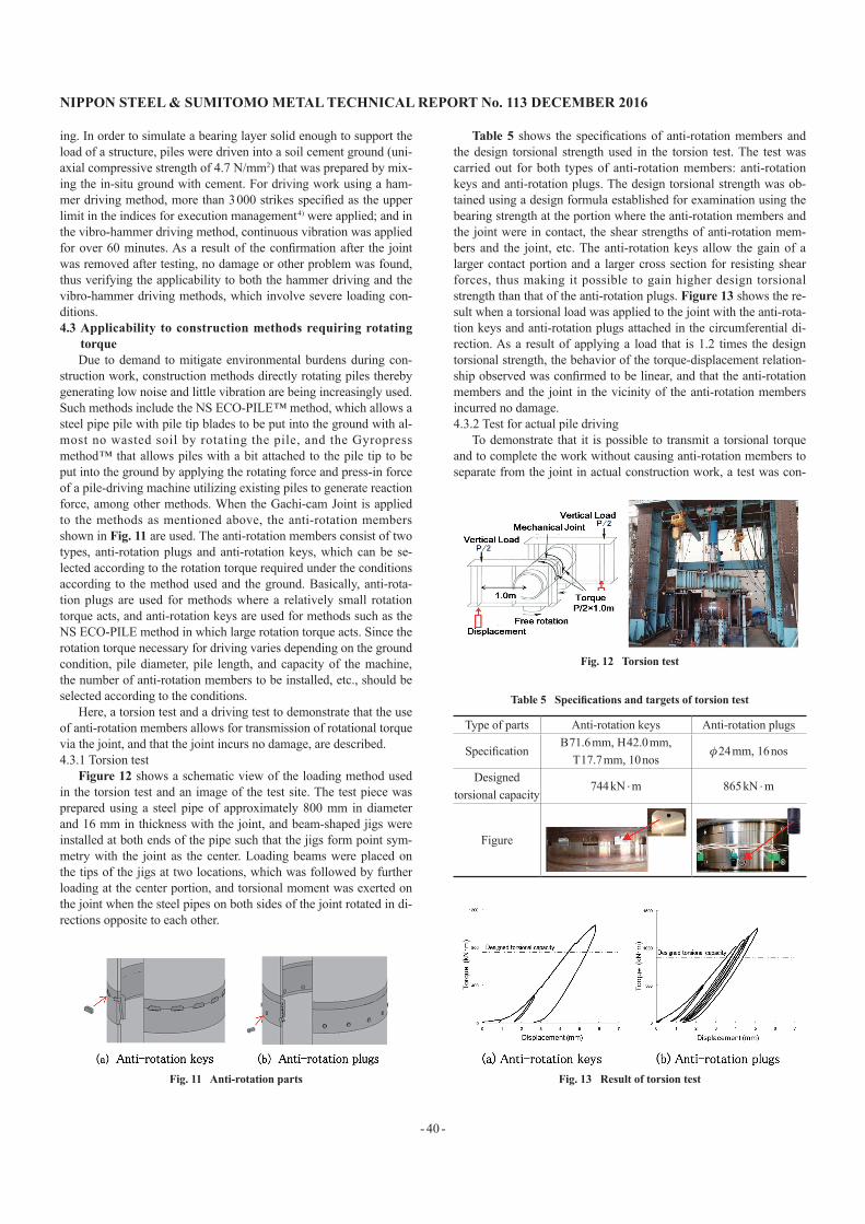
Figure 12 shows a schematic view of the loading method used in the torsion test and an image of the test site. The test piece was prepared using a steel pipe of approximately 800 mm in diameter and 16 mm in thickness with the joint, and beam-shaped jigs were installed at both ends of the pipe such that the jigs form point sym-metry with the joint as the center. Loading beams were placed on the tips of the jigs at two locations, which was followed by further loading at the center portion, and torsional moment was exerted on the joint when the steel pipes on both sides of the joint rotated in di-rections opposite to each other.
Table 5 shows the specifications of anti-rotation members and the design torsional strength used in the torsion test. The test was carried out for both types of anti-rotation members: anti-rotation keys and anti-rotation plugs. The design torsional strength was ob-tained using a design formula established for examination using the bearing strength at the portion where the anti-rotation members and the joint were in contact, the shear strengths of anti-rotation mem-bers and the joint, etc. The anti-rotation keys allow the gain of a larger contact portion and a larger cross section for resisting shear forces, thus making it possible to gain higher design torsional strength than that of the anti-rotation plugs. Figure 13 shows the re-sult when a torsional load was applied to the joint with the anti-rota-tion keys and anti-rotation plugs attached in the circumferential di-rection. As a result of applying a load that is 1.2 times the design torsional strength, the behavior of the torque-displacement relation-ship observed was confirmed to be linear, and that the anti-rotation members and the joint in the vicinity of the anti-rotation members incurred no damage.4.3.2 Test for actual pile driving
To demonstrate that it is possible to transmit a torsional torque and to complete the work without causing anti-rotation members to separate from the joint in actual construction work, a test was con-
Fig. 11 Anti-rotation parts
Fig. 12 Torsion test
Table 5 Specifications and targets of torsion test
Type of parts Anti-rotation keys Anti-rotation plugs
Specification B 71.6 mm, H 42.0 mm,
T 17.7 mm, 10 nosφ 24 mm, 16 nos
Designed torsional capacity
744 kN . m 865 kN
. m
Figure
Fig. 13 Result of torsion test

NIPPON STEEL & SUMITOMO METAL TECHNICAL REPORT No. 113 DECEMBER 2016
- 41 -
ducted using the Gyropress method , which is one of the construc-tion methods that uses rotational torque. Photo 6 shows the test site. The piles tested consisted of four single pipes of 800 mm in diame-ter and 6 m in length, and joints were attached to three locations where the joints were supposed to be installed at a construction site, and the specifications for anti-rotation members (anti-rotation keys: one location; anti-rotation plugs: two locations) were determined based on a control torque that is determined by the driving condi-tions. The piles were driven up to a depth of 21 m, while the piles were embedded about 2 m deep into the bearing layer with an N value over 50. According to the examination conducted after the piles were pulled out, it was confirmed that no damage or separation occurred in the joint body or any of the locations of the anti-rotation members. The results of the above torsion test and driving test veri-fy that the Gachi-cam Joint is also applicable to construction meth-ods that involve rotational torques.
5. ConclusionIn this paper, the development of the Gachi-cam Joint, a new-
model mechanical joint, is explained. A detailed consideration in-cluding issues regarding fracture tests has successfully led to the re-alization of a joint that is capable of satisfying both the required structural performance and thorough rationalization simultaneously. In addition, the driving test as conducted has verified favorable jointing workability, applicability to the hammer driving and vibro-hammer driving methods in which severe loads are applied during the work, and applicability to driving methods that involve applying rotational torques increasingly being adopted due to environmental performance. By offering this new-model joint, we would like to continue contributing to overcoming various issues surrounding the construction field, including a guarantee of the construction quality expected to be increasingly demanded from now on, scarcity of highly skilled workers, measures to cope with rapid work demands arising from needs for maintenance and renewal of existing struc-tures, and so forth.
References1) Public Works Research Center: Report of Construction Technology Re-
view and Certification, Mechanical Joint for Steel Pipe Piles and Steel Pipe Sheet Piles “Laqnican joint”. 2012
2) Coastal Development Institute of Technology: Report No. 03002 on Confirmatory Examination, Evaluation on Private Technologies for Port and Harbor Construction, Mechanical Joint for Steel Pipe Piles and Steel Pipe Sheet Piles “Laqnican joint”. 2009
3) The Building Center of Japan: BCJ Certification of Non-Welded Joint for Steel Pipe Piles “Hi-SHJ”. 2005
4) For instance, Japanese Technical Association for Steel Pipe Piles and Sheet Piles: Steel Pipe Pile—Design and Construction Work. 2009
Masashi KITAHAMASenior ResearcherSteel Structures Research Lab.Steel Research Laboratories20-1 Shintomi, Futtsu City, Chiba Pref. 293-8511
Toshihiko SAKAMOTOManagerKyushu Marketing BranchConstruction Products Dept.
Yoshiro ISHIHAMASenior ResearcherSteel Structures Research Lab.Steel Research Laboratories
Shinji TAENAKASenior Researcher, Ph.D.Steel Structures Research Lab.Steel Research Laboratories
Hironobu MATSUMIYASteel Structures Research Lab.Steel Research Laboratories
Tadachika MOCHIZUKILarge Diameter Pipe Quality Control Dept.Quality Management Div.Kimitsu Works
Yoshinori FUJIISenior ManagerFoundation Products Engineering Dept.-IConstruction Products Development Div.Construction Products Unit
Hiroyuki TANAKAGeneral Manager, Head of Dept., Dr. Eng.Foundation Products Engineering Dept.-IConstruction Products Development Div.Construction Products Unit
Photo 6 Driving test by Gyropress method


![[ARC2513] Building construction2 project 2](https://img.pdfslide.us/doc/110x75/55a8eb8b1a28abb32b8b458f/arc2513-building-construction2-project-2.jpg)