Embed Size (px)
Citation preview

Technical Report Documentation Page 1. Report No. R-1538
2. Government Accession No.
3. MDOT Project Manager 5. Report Date February 2010
4. Title and Subtitle Fifteen Year Performance Review of Michigan’s European Concrete Pavement 6. Performing Organization Code
7. Author(s) David L. Smiley
8. Performing Org. Report No. 10. Work Unit No. (TRAIS) 11. Contract No.
9. Performing Organization Name and Address Michigan Department of Transportation Construction and Technology Division P.O. Box 30049 Lansing, MI 48909
11(a). Authorization No. 13. Type of Report & Period Covered
12. Sponsoring Agency Name and Address Michigan Department of Transportation Construction and Technology Division P.O. Box 30049 Lansing, MI 48909
14. Sponsoring Agency Code
15. Supplementary Notes
16. Abstract In 1993, a special pavement demonstration project was constructed in Detroit on NB I-75 to evaluate the design features of some highly acclaimed European rigid pavements. The Michigan Department of Transportation (MDOT) and the Federal Highway Administration (FHWA) agreed to this project after an extensive inquiry of European pavements, including a 1992 technical tour of pavements in Germany and Austria to gain insight into their specific design features and construction practices for duplication with the Detroit project. MDOT has monitored the project’s performance for the past sixteen years since construction. The results from the I-75 European project continue to generate nationwide interest amongst pavement enthusiasts. This report is a compilation of the condition data of the Euro-pavement since its construction. Because MDOT considered this demonstration project a valuable research opportunity, a rigid pavement “control section” was included on NB I-75 adjacent to the one-mile long Euro-pavement. The control section represented MDOT’s standard rigid pavement design used during that era. This report also documents preservation contract work performed on both pavement sections in 2008 to repair pavement distress to extend their respective service lives. The report also describes investigative work into the cause of the distress that initiated the 2008 preservation project. Both the Euro-pavement and MDOT’s control section pavement are performing satisfactorily. Neither is showing a distinct performance trend to be able to predict either pavement’s eventual service life expectancy. In the interim, MDOT has benefited from the project by using its limited results to enhance its present rigid pavement design to extend its service life. 17. Key Words
18. Distribution Statement No restrictions. This document is available to the public through the Michigan Department of Transportation.
19. Security Classification - report Unclassified
20. Security Classification - pageUnclassified
21. No. of Pages 49
22. Price


MICHIGAN DEPARTMENT OF TRANSPORTATION MDOT
Fifteen Year Performance Review of Michigan’s European
Concrete Pavement
David L. Smiley
Construction and Technology Division Research Report R-1538
Michigan Transportation Commission Ted B. Wahby, Chairman
Linda Miller Atkinson, Vice Chairwoman Maureen Miller Brosnan, Jerrold Jung
Steven K. Girard, James S. Scalici Kirk T. Steudle, Director
Lansing, Michigan February 2010


TABLE OF CONTENTS Executive Summary .............................................................................................................1 Introduction..........................................................................................................................2 Project Background..............................................................................................................3 European Pavement Features...................................................................................3 Michigan Pavement Features...................................................................................6 Performance History ............................................................................................................7 Historical Condition Data ........................................................................................8 Current Pavement Condition..............................................................................................12 2008 Preventive Maintenance Project ...............................................................................18 Summary Review and Conclusions ...................................................................................21 Appendix............................................................................................................................23
i
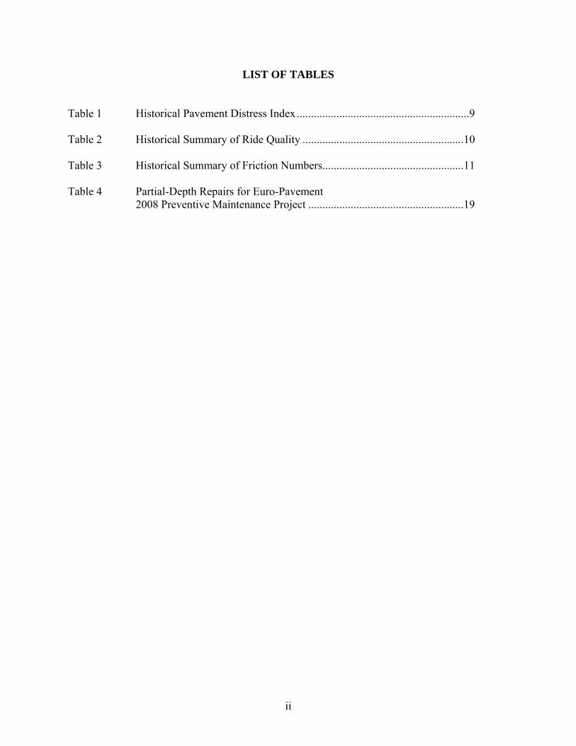
LIST OF TABLES Table 1 Historical Pavement Distress Index .............................................................9 Table 2 Historical Summary of Ride Quality .........................................................10 Table 3 Historical Summary of Friction Numbers..................................................11 Table 4 Partial-Depth Repairs for Euro-Pavement 2008 Preventive Maintenance Project .......................................................19
ii

LIST OF FIGURES Figure 1 European Demonstration Project Location..................................................2 Figure 2 European Pavement Section ........................................................................4 Figure 3 Present Condition of Exposed-Aggregate Surface ......................................5 Figure 4 Michigan Pavement Cross Section ..............................................................6 Figure 5 Typical Longitudinal Crack with Euro-Pavement .....................................12 Figure 6 Contrast in Crack Width per Depth of Euro-Pavement Longitudinal Crack ....................................................................................13 Figure 7 Beginning Spall of Euro-Pavement ...........................................................14 Figure 8 Spall on Both Sides of Transverse Joint of Euro-Pavement ......................14 Figure 9 High Severity Spall/Delamination of Euro-Pavement...............................15 Figure 10 Exposed Lean Concrete Base of Euro-Pavement ......................................20
iii

EXECUTIVE SUMMARY In 1993, a special demonstration project was constructed in Detroit on NB I-75 (Chrysler Freeway) to present some highly acclaimed features of European rigid pavements to pavement practitioners in the United States. The Federal Highway Administration (FHWA) and the Michigan Department of Transportation (MDOT) collaborated on the project to learn whether the unique features of European rigid pavements could be adapted cost-effectively to enhance the performance of more conventional pavement designs used in the United States. MDOT included the special one-mile long ‘Euro-pavement’ in a project to reconstruct I-75 from I-375 N’ly to north of the I-94 interchange in northwest Detroit. The pavement portion of NB I-75 directly south of the Euro-pavement has been used since construction as a Michigan ‘control section’ to compare its performance with the Euro-pavement. This report summarizes the performance of the Euro-pavement and the Michigan control section pavement since their construction 16 years ago. The European demonstration project still generates queries from pavement enthusiasts nationwide who actively follow its performance. This report also documents preservation repairs made to both pavements during a 2008 preventive maintenance project, including results from earlier field investigations in 2007 that looked for a cause for the pavement distress to be repaired. To date there is no clear indication as to which pavement section will eventually achieve the most cost-effective service life. The Euro-pavement’s initial construction cost was more than twice the cost of the Michigan pavement section, which can be mostly attributed to its special features (exposed aggregate texture, structural enhancements). Today, both pavements have a low distress index and similar ride quality values (RQI/IRI). A distinct performance trend has not developed for either pavement section to be able to estimate a definitive service life expectancy. However, considering its substantial initial cost factor, the future preservation cost of the Euro-pavement will need to be much lower than the Michigan pavement section to be cost equivalent for its service life. In the interim period, the project results have fortified some changes MDOT has made in designing and constructing rigid pavements to improve their long-term performance. The changes include a design shift from JRCP to JPCP that began shortly after the construction of the Euro-pavement project and continued through the 1990s. And, improvements have been made to enhance concrete pavement mixtures and their construction placement procedures under QC/QA control.
1

INTRODUCTION In 1993, the Michigan Department of Transportation (MDOT) and the Federal Highway Administration (FHWA) fulfilled an agreement to construct and evaluate a rigid pavement that assimilated unique European design features. MDOT included the special pavement section, known as the “European Pavement”, as part of the reconstruction of NB I-75 (IM 82251-30613A) that occurred during the fall of 1993. Figure 1 shows the Euro-pavement location, which is northwest of downtown Detroit. This report updates its performance after fifteen years of service and includes documentation of contracted maintenance repairs performed in 2008.
FIGURE 1
European Demonstration Project Location
2

PROJECT BACKGROUND In early 1992, the FHWA conducted a technical tour of several European countries to gain insight into their design and construction practices of concrete (rigid) pavements. The tour found1 that European countries are designing and constructing excellent concrete pavements for heavier truck loadings than are allowed in the United States. The European countries generally emphasize a longer service life by using higher quality materials and stringent construction practices. These factors increase initial cost, but are found to be acceptable to achieve the desired result. The findings from the FHWA technical tour encouraged a subsequent technical tour2 in October 1992, which included MDOT representatives. The tour’s purpose was to review specific design and construction techniques in Germany and Austria for application with U.S. projects, particularly with Michigan’s I-75 demonstration project in Detroit3. Michigan’s “European Pavement” demonstration project was constructed from July to November 1993. The approximately one-mile long project is located on NB I-75 (Chrysler Freeway) between Warren Avenue and Piquette Avenue, which includes the interchange with I-94. The portion of NB I-75 directly south of the Euro-pavement was also reconstructed at the same time (same contract) using MDOT’s concrete pavement design from that time period (see Michigan Pavement Features). Its’ performance has been contrasted with the Euro-pavement since their mutual construction. The details of both pavement’s design features and construction results are documented in previously published reports4 by MDOT and the FHWA. A summary reminder of the Michigan and Euro-pavement’s design features and construction are provided in this report. Greater detail, including as-constructed results, can be found in the cited references. European Pavement Features The Euro-pavement’s structural layer thicknesses and material characteristics were dictated from the German design catalog for the climatic, soil and traffic conditions similar to Detroit. The typical section is three to four lanes wide with the outer pavement slabs widened to 13.5 ft. from the conventional 12 ft. width. Figure 2 is a schematic of the Euro-pavement’s cross section.
1“Report on the 1992 US Tour of European Concrete Highways”, US Tech, Sponsors were: AASHTO, ACPA, FHWA, PCA, SHRP, TRB. 2“European Concrete Pavement Tour”, Michigan Department of Transportation, November 1992, authors Roger D. Till and Randy VanPortfliet. 3The I-75 project was intended to coincide with AASHTO’s annual meeting in Detroit, which was recognizing the 100th anniversary of the automobile. 4“Construction of European Concrete Pavement on Northbound I-75 – Detroit, Michigan”, Michigan Department of Transportation, Report No. R-1333, September 1994. “Demonstration Project No. 75 - Michigan Demonstration Project I-75 Detroit, Michigan”, Federal Highway Administration, March 1994.
3

FIGURE 2
European Pavement Section NB I-75
Subgrade and Subbase Sound, uniform structural support is highly emphasized with European designs, which the Euro-pavement represented. The local subgrade soil is a lacustrine silty clay. During construction, after the complete removal of the old I-75 pavement structure, it was thoroughly inspected for potential frost heaving and compaction was held to a minimum 95 percent of its maximum unit weight. A crushed limestone was used to construct the 16 in. thick (two 8 in. lifts) aggregate subbase. A well-graded aggregate (low permeability) was specified to comply with the German protocol. Compaction was required to be a minimum 100 percent of its maximum unit weight. Lean Concrete Base The 6 in. thick lean concrete base (LCB) was constructed on the aggregate subbase. The specified 2500 psi design strength was easily achieved. The mix design used a Type I Portland cement (420 lbs/cyd) from LaFarge Corporation, Alpena, a natural sand fine aggregate, and a crushed limestone (ASN 71-47) coarse aggregate. The non-reinforced slab has sawed transverse relief cuts (0.4D) at 15 ft. joint spacing that match location with the joint pattern in the two-layer, concrete surface pavement. Two-Layer Concrete Surface Pavement The 10 in. thick surface pavement consists of two-layers (placed wet on wet) using different concrete mixtures. The bottom layer is a nominal 7½ in. thick, while the top layer is 2½ in. thick. Separate batching facilities and delivery equipment were used to coordinate each concrete mixture. Verification coring during construction found the top and bottom layer thickness to be highly variable, but the overall slab thickness held to the 10 in. target. The same sources for cement and aggregate used for the lean concrete base were also used to construct the surface pavement, except the coarse aggregate for the top layer was changed. A crushed basalt stone (ASN 95-10) was used to meet the wear (polishing) requirements when exposed for the aggregate surface texture. The aggregate size was essentially uniform with a top size of ⅓ in. (8mm). Coarse 2NS sand filled the gradation gaps. The specified design strength
4

requirements for the layers were 5500 psi top-layer and 5000 psi bottom-layer. The compressive strength requirement was mostly achieved without difficulty, but some top-layer areas were found to have low strength with corresponding high total air content (ASTM C-457). Coring found no evidence of a cold joint between the two surface layers. Some partial bonding with the lean concrete base was also confirmed. Bonding between the LCB and the two-layer pavement was neither promoted, nor discouraged. Exposed Aggregate Surface The top layer of the two-layer surface pavement was constructed to expose the basalt aggregate to provide surface texture. The objective was to reduce tire interaction noise and improve frictional characteristics. The construction process followed a patented procedure (International Patent No. 0086188) that was developed by Robuco Ltd, of Belgium. Briefly, the freshly placed concrete was sprayed with a set retarder and then covered with two-mil plastic sheeting. The sheeting was removed the next day (after 20 hours) and the surface was brushed to expose the coarse aggregate. An average texture depth of about 1.0 mm was achieved, which was less than the intended target value of 1.1 to 1.5 mm. Figure 3 shows a typical photo example of the present texture condition. To date, there has been minimal loss of exposed stone.
FIGURE 3
Present Condition of Exposed-Aggregate Surface Transverse and Longitudinal Joints Transverse contraction joint spacing is 15 ft. that matches the relief cuts in the LCB. Expansion joints were installed only at the ending limits of the Euro-pavement. The 20 in. long by 1¼ in.
5
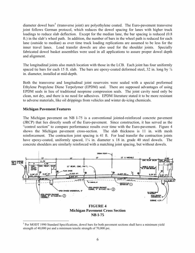
diameter dowel bars5 (transverse joint) are polyethylene coated. The Euro-pavement transverse joint follows German protocol, which reduces the dowel spacing for lanes with higher truck loadings to reduce slab deflection. Except for the median lane, the bar spacing is reduced (0.8 ft.) in the slab’s wheel path. In addition, the number of bars in the wheel path is reduced for each lane (outside to median) as over time truck loading replications are assumed to be less for the inner travel lanes. Load transfer dowels are also used for the shoulder joints. Specially fabricated dowel basket assemblies were used in all applications to assure proper dowel depth and alignment. The longitudinal joints also match location with those in the LCB. Each joint has four uniformly spaced tie bars for each 15 ft. slab. The bars are epoxy-coated deformed steel, 32 in. long by ⅞ in. diameter, installed at mid-depth. Both the transverse and longitudinal joint reservoirs were sealed with a special preformed Ethylene Propylene Diene Terpolymer (EPDM) seal. There are supposed advantages of using EPDM seals in lieu of traditional neoprene compression seals. The joint cavity need only be clean, not dry, and there is no need for adhesives. EPDM literature stated it to be more resistant to adverse materials, like oil drippings from vehicles and winter de-icing chemicals. Michigan Pavement Features The Michigan pavement on NB I-75 is a conventional jointed-reinforced concrete pavement (JRCP) that lies directly south of the Euro-pavement. Since construction, it has served as the “control section” to compare performance results over time with the Euro-pavement. Figure 4 shows the Michigan pavement cross-section. The slab thickness is 11 in. with mesh reinforcement. The contraction joint spacing is 41 ft. For load transfer the contraction joints have epoxy-coated, uniformly spaced, 1¼ in. diameter x 18 in. grade 40 steel dowels. The concrete shoulders are similarly reinforced with a matching joint spacing, but without dowels.
FIGURE 4
Michigan Pavement Cross Section NB I-75
5 Per MODT 1990 Standard Specifications, dowel bars for both pavement sections shall have a minimum yield strength of 40,000 psi and a minimum tensile strength of 70,000 psi.
6

The reconstruction of SB I-75, directly adjacent (same contract ending limits) to the Euro-pavement and Michigan pavement section, was also part of the contract work. It was re-built the following year in 1994. A contract revision was made to modify the southbound portion by shortening the transverse contraction joint spacing to 27 ft.6 from the 41 ft. that was used for the NB direction. All other design features of SB I-75 are the same as constructed for NB I-75. The aggregate for the open-graded drainage course (OGDC) is a Michigan series 5G gradation that was made by crushing the old I-75 concrete pavement. The OGDC is stabilized with Portland cement at 6 percent, by weight of the aggregate. A geotextile (non-woven fabric) separates the OGDC from the 12 in. thick sand subbase (original to I-75). During construction of NB I-75, however, the geotextile was inadvertently placed across the shoulder drain trench as the plan cross section drawing was misinterpreted. The drain type matches the Euro-pavement, but its location is under the shoulder, 2 ft. from the longitudinal joint. The specified design requirements for the concrete mixture were 3500 psi (28 day) compressive strength, 650 psi (28 day) flexure strength, 3 in. max. slump, 550 lbs/cyd min. Portland cement content, and a maximum 0.50 w/c ratio. The Euro-pavement and the Michigan section used the same coarse aggregate (carbonate7). The Michigan pavement surface texture is transverse tinned (non-skew) at a nominal ¾ in. spacing with some intended randomness.
PERFORMANCE HISTORY MDOT and FHWA agreed to closely monitor the performance of the Euro-pavement for the first five years after its construction. Yearly performance reports8 were prepared by MDOT for the project’s first three years. After about five years MDOT contracted with Michigan State University (MSU) to conduct a study9 to evaluate the cost effectiveness of both pavement sections by comparing their respective construction costs and any detectable performance trends that had occurred since construction. The MSU study found that condition data since construction showed no apparent trend for either pavement type to predict a clear outcome for their eventual service life duration. As an
6The Michigan DOT during this time period was using both joint spacings for JRCP depending upon the amount of anticipated truck traffic to correspond with the potential for transverse cracks developing. The change was made to 27 ft. on SB I-75 to allow a comparison in performance to take place. All other design features and material sources remained the same with NB I-75. 7The project specified a coarse aggregate with high durability requirements with a maximum dilation value of 0.008 percent per 100 freeze-thaw cycles per MTM 115. The aggregate sampling and acceptance requirements were also modified for this project and applied to both pavements. 8MDOT published the following three reports:
Report No. R-1338 – “First Year Performance of the European Concrete Pavement on Northbound I-75, Detroit, Michigan” February 1995. Report No. R-1343 – “Second Year Performance of the European Concrete Pavement on Northbound I-75, Detroit, Michigan” June 1996. Report No. unknown – “Third Year Performance of the European Concrete Pavement on Northbound I-75, Detroit, Michigan” March 1997.
9Report No. RC-1381 – “Cost Effectiveness of European Demonstration Project: I-75 Detroit” May 2000.
7

alternative, MSU used MDOT’s maintenance schedule10 for concrete pavement and their respective construction (bid item) costs for a hypothetical economic comparison. That analysis concluded the Euro-pavement’s initial capital cost11 could not exceed that of the conventional Michigan pavement cost by more than approximately 17 percent for both pavement types to be considered equivalent on an expected annualized cost basis. Historical Condition Data The primary performance parameters for comparing the Euro-pavement and Michigan section have been surface distress characteristics, ride quality and surface friction. The following discussion is an update from the last (third year - 1997) MDOT performance report. Current directional daily traffic is approximately 73,500 vehicles with 7 percent commercial volume. MDOT’s Pavement Management System (PMS) data files are the exclusive source for the following data. Surface Distress Michigan combines the extent and severity of surface distress features to create a “distress index (DI)” value. A newly constructed pavement has a DI equal to zero. When the pavement’s condition reaches a DI value of 50, preventive maintenance treatments are no longer considered to be cost effective to extend service life. Hence, major rehabilitation or reconstruction becomes the only cost-effective option. A DI value is created for each 0.1 mile increment of pavement. Freeway pavements, like I-75, are surveyed on a two year cycle. The right outside lane in each travel direction is normally selected for distress measurements, which are done at normal traffic speed by video taping the pavement’s surface. The tapes are later analyzed to quantify and document distress features. Table 1 is the historical summary of the pavement’s DI for the European and Michigan pavements since construction. The latest available data are for 2007. The data shows the average DI has not changed significantly for either pavement type since their construction. The higher European DI score in 1997 was related to a visual condition that was considered distress related, but dropped from future scoring after further investigation. The higher DI range value for 2007 for Euro-pavement is confined to a single 0.1 mile segment near the southerly limit of the pavement section. Isolated concentrations of distress are normally induced by adverse construction practices.
10MDOT uses an assumed schedule of needed preventive maintenance treatments during a pavement’s service life, which is estimated at 35 years. Each treatment action is intended to add service life. During design for pavement type selection, the life/cycle cost of equivalent flexible and concrete pavements are compared, if the pavement cost exceeds one million dollars. The type with the lowest cost is selected. 11The construction cost (using only pavement pay items) per unit area of the Euro-pavement was about 2½ times the cost of the Michigan section. The Euro-pavement cost included special features (exposed texture, joint seals, LCB) and adjustments to the paving schedule which inflated its overall project cost.
8
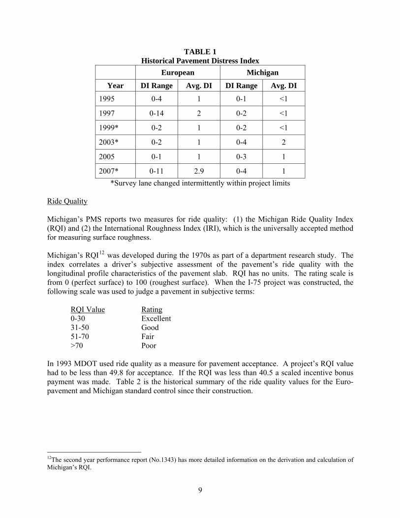
TABLE 1 Historical Pavement Distress Index
European Michigan
Year DI Range Avg. DI DI Range Avg. DI
1995 0-4 1 0-1 <1
1997 0-14 2 0-2 <1
1999* 0-2 1 0-2 <1
2003* 0-2 1 0-4 2
2005 0-1 1 0-3 1
2007* 0-11 2.9 0-4 1 *Survey lane changed intermittently within project limits
Ride Quality Michigan’s PMS reports two measures for ride quality: (1) the Michigan Ride Quality Index (RQI) and (2) the International Roughness Index (IRI), which is the universally accepted method for measuring surface roughness. Michigan’s RQI12 was developed during the 1970s as part of a department research study. The index correlates a driver’s subjective assessment of the pavement’s ride quality with the longitudinal profile characteristics of the pavement slab. RQI has no units. The rating scale is from 0 (perfect surface) to 100 (roughest surface). When the I-75 project was constructed, the following scale was used to judge a pavement in subjective terms: RQI Value Rating
0-30 Excellent 31-50 Good 51-70 Fair >70 Poor In 1993 MDOT used ride quality as a measure for pavement acceptance. A project’s RQI value had to be less than 49.8 for acceptance. If the RQI was less than 40.5 a scaled incentive bonus payment was made. Table 2 is the historical summary of the ride quality values for the Euro-pavement and Michigan standard control since their construction.
12The second year performance report (No.1343) has more detailed information on the derivation and calculation of Michigan’s RQI.
9

TABLE 2 Historical Summary of Ride Quality
European Michigan
Year RQI Range/avg.
IRI Range/avg.
RQI Range/avg.
IRI Range/avg.
Dec. 1993 30-52/41 73-106/94 30-69/44 44-98/53
Feb. 1995 43-54/47 74-139/102 34-52/43 53-99/72
Feb. 1997 40-50/48 65-105/80 29-54/40 45-90/66
1999 40-57/47 81-122/95 40-58/46 69-104/84
2001*
2003 42-53/48 80-107/91 32-54/45 72-180/93
2005 40-68/50 80-122/97 37-54/47 65-126/86
2007 46-79/60 79-180/115 43-65/54 66-121/88 *The 2001 data are not included because they have questionable accuracy due to a change in calculation method. After 2001, a profile for each wheel-path is measured, and then the two values are averaged to calculate the value shown for those years.
Neither pavement shows a definite trend, as the measurements are mixed. The IRI values have tended to increase at a more rapid rate than has RQI. As expected, the quality of ride has declined since construction, but overall is still acceptable. Surface Friction A Friction Number (FN) represents the available wet-sliding friction for a pavement surface at a test site. The value is determined using a tow trailer with full size tires in a locked position. Test parameters are in accordance with ASTM E-274. The field test values are converted to equivalent standard FN units using a correlation equation developed at the Field Test and Evaluation Center for Eastern States located in East Liberty, Ohio. Table 3 is a historical summary of FN values since construction for each lane. The November 1993 values were determined prior to traffic opening after paving. The April 1994 values were taken the following spring before SB I-75 traffic was detoured onto northbound to facilitate reconstruction of the southbound pavement.
10

TABLE 3 Historical Summary Of Friction Numbers
European Michigan
Lane Lane Date
1 2 3 1 2 3
Nov. 1992 35 36 42 49 46 44
April 1994 44 42 40 54 53 52
Oct. 1997 33 32 35 44 43 48
July 2000 40-43 35-41 35-36 53-60 45-53 37-50
July 2003 33-37 34-36 32-37 52-52 46-47 39-46
July 2006 39-42 34-42 33-36 55-55 45-49 44-47 Notes: Values for 1993, 1994, and 1997 are averages for project length. Values since are low and high values for project length. Lane 1 is adjacent to median concrete barrier.
Since the project has been opened to normal traffic, the FN values for both pavement surfaces have remained consistent. The Michigan tinned surface has consistently measured higher FN values, in contrast to the European exposed aggregate surface, which has stabilized in the middle 30s. The European exposed aggregate surface was intended to improve friction characteristics versus a traditional tinned surface. Early performance reports pondered reasons why this enhancement was not realized. The most likely possibility focused on the excessive aggregate spacing that increased macro-texture as the most plausible explanation. Noise Study The Euro-pavement’s exposed aggregate surface texture was intended to reduce noise levels from tire interaction with the pavement. In 1994, MDOT conducted an evaluation13 of both pavement sections to determine if any discernable differences existed. The study occurred when SB I-75 was being reconstructed and its traffic was shifted to the NB direction. NB I-75 traffic was detoured during construction of SB I-75. The study found the Leq14 noise levels for the Euro-pavement to be only 0.4 dBA quieter (76.0 vs. 76.4) than the tinned texture of the Michigan section.
13The complete report of the noise study is contained in MDOT’s 1st year performance report (R-1338). The Euro-pavement has been used as a test site for other national noise studies. 14 The “level equivalency” (Leq) considers the overall noise level measured. The measured locations were 56 ft. from the traffic lane, so they would capture all producers of noise.
11

CURRENT PAVEMENT CONDITION In 2006, the Metro Region reported that the Euro-pavement was developing longitudinal cracking (LC) and intermittent areas of severe surface spalling. This condition was found during routine field distress reviews of region-wide pavements. A more detailed condition review was made which justified the need for a Capital Preventive Maintenance (CPM) project. The Metro Region scheduled the CPM project for 2008 in conjunction with major bridge rehabilitation work along the I-75 corridor in Detroit. In February 2007, to prepare a fix plan for the CPM project, pavement cores of cracked and un-cracked slabs were made to help determine a cause for the distress. The coring was located only in the outside right lane that was closed to traffic. The field report for the February investigative work is included in the appendix. Euro-Pavement Distress Condition The longitudinal cracking is intermittent over the project length, but occurs mostly amongst groups of two and three contiguous slabs. Cracks have slight wander and occur in the right third of the slab width (13.5 ft.), shoulder side of the right wheel-path. It may skip to the next slab with a slight offset at a transverse joint. A picture of a slab with a typical longitudinal crack is shown in Figure 5, when it was replaced. Most cracking is occurring in the outside right lane.
FIGURE 5
Typical Longitudinal Crack with Euro-Pavement
12

The February 2007 coring found cracks to be full-depth through the 10 in. two-layer, surface pavement. There was no indication that the longitudinal cracks are reflective, as no cracking was found below in the lean concrete base. Where cracks existed, the cores found no bond between these pavement layers, as well as, no indication of scour or erosion at their interface. The crack width was noticeably wider through the 7½ in. carbonate portion of the 10 in. layer, which would indicate the cracks are forming bottom-up. Figure 6 is a core which depicts the contrast in crack width between the layers. Where multiple cores were taken in the same panel, the lower crack width (7½ in. portion) was wider near mid-panel, compared to near a transverse joint.
FIGURE 6
Contrast in Crack Width per Depth of Euro-Pavement Longitudinal Crack Areas of surface spalling were also cored. Visually, the spalling is not confined to any particular lane or location within the project limits, but does occur mostly adjacent to joints and cracks. The cores showed the spalling to more resemble a delamination action within the 2½ in. thick top-layer, and not at its interface with the carbonate layer. Sounding with a heavy metal rod or hammer produced a classic hollow-thud, indicating internal separation. Site inspection of the cores showed the top-layer concrete was poorly consolidated with indication of possible freeze-thaw deterioration. Figures 7 through 9 show a series of picture examples of the severity levels of the surface spalling from a starting condition without breakup to where patching with cold-patch becomes necessary.
13

FIGURE 7
Beginning Spall of Euro-Pavement Note: White substance in crack is salt (de-icing) residue.
FIGURE 8
Spall on Both Sides of Transverse Joint of Euro-Pavement
14

FIGURE 9
High Severity Spall/Delamination of Euro-Pavement Two consecutive panels without distress were cored near mid-panel to determine if any bond existed with the underlying lean concrete base (LCB). The cores found the layers bonded, such that minor disturbance and handling of the cores did not break the bond. 2007 FHWA Site Visit In early April 2007, FHWA representatives from Washington DC and their local Michigan Division office conducted a site review of the condition of the Euro-pavement and the Michigan control section to affirm the fix actions for the upcoming CPM project in 2008. The FHWA field report of their site review is included in the appendix. A summary of findings follows herein. As in February, the right outside lane of the Euro-pavement was closed to traffic for coring and to provide a closer visual inspection. Two adjacent panels exhibiting typical longitudinal cracking were cored through the cracks and in the adjacent shoulder over the outside drain trench. The cores through the cracks found the same condition as discovered in February. The cracks are full-depth, wider at the bottom, and there is no indication of scour occurring at contact with the LCB. Any bond with the LCB, if it ever existed, was non-existent at this time. The cores over the longitudinal edge drain trench15 were taken to determine how well the system was functioning. The core exposed the Michigan Series 34R (peastone) trench backfill. There was no indication that the trench liner may have been inadvertently placed over the trench backfill during construction. Several gallons of water were continuously poured into the core hole which freely dispersed into the trench backfill without backup. 15The center of the trench is directly below the longitudinal slab/shoulder joint. The 6 in. diameter pipe lies just above subgrade elevation.
15
At several locations, including the fore-mentioned core location, the drain pipes were inspected for possible obstructions with a video camera used for pipe inspections. The camera inspection began at the drain outlets at catch-basins along the outside edge (valley-gutter) of the shoulder. The camera inspection results were inconclusive. At all eight locations the camera could only enter the drain a short distance from the catch-basin due to severe bends in the 6 in. diameter corrugated plastic pipe. At most locations water was observed passing through the pipe into the drainage structure. No coring was done at surface spall/delamination areas as no additional confirmation of their condition was believed warranted. The FHWA recommendation was the delaminated areas should be repaired with traditional partial depth patching methods. The condition of the Euro-pavement joint seals was also discussed, as they are being considered for replacement during the CPM project. Since construction, the EPDM material has dropped lower in the joint cavity with occasional humping. In many areas the depressed area is significant enough, where debris, incompressibles, and de-icer material can lodge causing possible concrete damage. Both FHWA and MDOT review members agreed with MDOT’s previous recommendation to replace the EPDM seals with hot-pour rubber sealant, but to leave a group of EPDM seals in-place (see 2008 Preventive Maintenance Project) for future comparison. Possible Causes for Distress Deterioration The Euro-pavement is experiencing two distinct, but independent distress patterns: (1) longitudinal cracking near the right wheel-path and (2) delamination of the exposed aggregate surface layer adjacent to transverse cracks. Findings from the February and April site investigations provide the following plausible explanations: Longitudinal Cracking
● Water intrusion between the 10 in. two-layer surface slab and the LCB is occurring. There are two apparent sources for the water; (1) entry through the longitudinal shoulder joint and (2) internal ground seepage, under head pressure from the adjacent cut slopes16. FHWA opinion is that both theories are plausible, but the seepage hypothesis was favored because of the existing site condition17.
● Water upon entering the interface between the 10 in. surface slab and LCB, begins to
degrade any bond. During winter it freezes, then acting as a fulcrum lifts the outside edge of the 10 in. surface slab. The lifting action (ice formation) forms a gap (void space) adjacent to the ice formation, leaving that portion of the slab unsupported during truck loading. A tensile stress forms in the area of this gap at the bottom of the slab.
16The Euro-pavement section of I-75 is a cut section, typically 10-15 ft. below street grade. 17The back slopes exhibited seepage areas during the April site review. Occasionally, water was also ponding (from likely snow melt) in the grass area at the top of back slope between the service drive. Theory = Water is traveling under a head through the ground, eventually entering the pavement structure under the shoulder through the aggregate base.
16
From normal fatigue, especially during melting18, the crack initiates. Over time, the process continues and the crack propagates to the surface and free edge (joint). This postulate is supported by the fact that the LC is wider with depth (bottom-up initiated).
● The LC may also be related to a restrained differential lateral movement between the
layers from a varying bond condition and differing thermal gradients with the layers. Here, the LC would initiate along the bond perimeter, working inward from the longitudinal shoulder joint. Water entry at the interface would also exacerbate this action.
Top-Layer Delamination As stated, the surface delamination of the exposed aggregate surface layer is easier to explain. The delamination appears to be solely material-moisture related. The joint cavities are retaining water and de-icer (chloride) materials, providing a source for freeze-thaw action and/or degradation of the concrete’s air-void system from infilling. MDOT conducted a petrographic examination and hardened air determination of core samples to confirm this assumption. The report with results is included in the appendix. The examination did find the air-void system exhibited post-construction deposits, most likely a carbonate formation that is compromising freeze-thaw resistance. Measured entrained air properties are marginal per PCA guidelines. Although no permeability testing was performed, microscopic examination of the cores and broken pavement fragments indicates the concrete is definitely highly susceptible (permeable) to water entry. The concrete breakup is occurring under traffic loading after internal expansion cracking from freezing action. Additional testing was done to determine the split tensile strength and the coefficient of thermal expansion (CTE) of the Euro-concrete layers. Three cores (carbonate bottom layer) were tested for split tensile strength. The results were 441-581-664 psi with an average of 562 psi, which meets specification requirements. The top-layer concrete and the lean concrete base were tested for CTE by the University of Michigan (UM) using their modified version of AASHTO TP60-00. A description of their test modification and a report of the results are included in the appendix. The CTE for the carbonate layer was approximately 3.9 x 10⁻⁶/°F, while the basalt top-layer was 4.5 x 10⁻⁶/°F. If the CTE difference between the layers (top-layer being higher) was significant, it could be a cause for the distress. But, that is not likely the case with these results. Michigan Pavement – Condition Comparison Compared to the Euro-pavement, the Michigan pavement (control section) has no pronounced distress features. The distress condition of the Michigan JRCP has remained about the same for the past ten years since completion of the MSU study. A visual walking assessment was made in the spring of 2008 when the entire NB direction of I-75 was closed to traffic during bridge 18After ice melting, which is likely rapid, the slab’s edge would be precariously unsupported and subjected to high deflections. Whether re-contact between the layers occurs is subject to conjecture.
17

rehabilitation activities. The estimated amount of slab cracking remains unchanged since the 1997 MDOT third year performance report. About 25-30 percent of the 41 ft. long slabs are cracked transversely (1-2 cracks/slab) with very few longitudinal cracks. The cracks are mostly low severity, straight, tight, and have minimal associated spalling. This explains why the distress index for the Michigan section has remained basically unchanged over time. The slight increase is from associated distress forming along joints and cracks and not because of additional crack formation.
2008 PREVENTIVE MAINTENANCE PROJECT In November 2007, the contract (IM 82251-79138A) for pavement repairs for the Euro-pavement, as well as the Michigan control section, was awarded. The proposed work was a small portion of a major contract (BHO 82252-59295A) for extensive bridge repairs along the I-75 corridor through northern Detroit and Hamtramck. All pavement repairs were done in 2008 when NB I-75 was closed to traffic for bridge repairs. Pavement repairs were done in accordance with MDOT’s 2003 Standard Specifications for Construction and applicable project Special Provisions (SP), which are included in the appendix. The pavement repairs consisted of the following major work items: Michigan Control Section
● Resealing all transverse and longitudinal joints with low-modulus, hot-poured rubber sealant.
● Removal of a weight-in-motion scale necessitating full-depth pavement replacement. ● Sealing an estimated 1300 lft. of transverse cracking with hot-poured rubber sealant. ● Partial-depth patching (est. 4 syds.) along cracks/joints (SP).
The existing neoprene seals in the transverse contraction joints were removed and the joint cavity cleaned with oil-free compressed air (min. 90 psi.) before re-sealing. The existing longitudinal joints used hot-poured rubber sealant, which was removed and the joint cavity similarly cleaned. European Pavement
● Full-depth slab (10 in. pavement only) replacement (SP). ● Partial-depth repairs (SP). ● Resealing transverse and longitudinal joints with low-modulus, hot-poured rubber
sealant. ● Crack sealing (design est. 200 lft.) with hot-poured rubber sealant.
EPDM Seal Replacement All existing EPDM seals were removed, except for 20 transverse EPDM seals that were left-in-place across all lanes (sta 128+31 to 143+02), which are near the south limit of the Euro-pavement section. The performance of these remaining EPDM seals will be monitored over time.
18

Partial-Depth Repairs The most extensive pavement work was partial-depth patching of the Euro-pavement spalling. Table 4 is a summary of the as-constructed patch sizes and distribution among the lanes. There were 100 patches totaling 340 sft. (38 syds.), which exceeded the plan estimate of 24 syds. The plan quantity estimate was derived from a distress survey made in November 2006. The dispersed patch distribution amongst lanes does not reflect traffic usage (repetitions) as much as one might conclude, although the 55 patches in the middle lane and the relative larger (> 3 sft.) repair area may be indicative of traffic. The Euro-pavement section normally consists of three lanes, so that lane receives the most traffic, when it becomes the ‘outside’ lane. Most likely19 the patch distribution reflects the particular daily conditions when a lane was paved and the characteristics of the top-layer concrete, as described previously. Also, the project’s construction (paving) progress was controlled.20 The majority of the Euro-pavement was paved during September/October time period and opened to full traffic in late November. Michigan fall weather conditions are generally beneficial for concrete paving.
TABLE 4 Partial-Depth Repairs For Euro-Pavement
2008 Preventive Maintenance Project Lane
Size Patch (Sft.) Median Middle Middle Outside
<1 2 0 1 3
1-2 11 8 14 2
>2-3 3 4 5 2
>3 5 1 35 4
Total # Patches 21 13 55 11 The surface concrete was removed by sawing the perimeter and the body of the repair area to an approximate 2 in. depth. A maximum 30 lb. chipping hammer was used to break the concrete. The area was cleaned with high-pressure (min. 3000 psi) water. The concrete patching mixture used a Michigan Series 29A coarse aggregate (carbonate), Type I Portland cement, 0.45 w/c ratio, water reducer, with 5.0-8.0 percent entrained air. It had been previously decided to not replicate the original top-layer concrete mixture/exposed aggregate surface for patching, including full slab replacement. The surface received a broom finish and was sprayed with white-membrane curing compound. All joints and full-depth cracks were maintained through the repair area with isolation joint material.
19This assumption is solely the opinion of the author who visited the site frequently during construction and was the research project manager when the early performance of the Euro-pavement was being monitored. 20Relative short lengths of a single lane in different areas of the project were paved to comply with the modified progress schedule. The construction schedule was modified to benefit AASHTO attendees who frequented the project via site tours. Construction records were not reviewed to match these site areas with partial-depth repair locations.
19

Full-Depth Repair Euro-pavement full-depth pavement repairs for longitudinal cracking were made in only two areas21 in the outside lane. The repair area included the entire slab width. The SP included a schematic of the repair detail, which is included in the appendix. The lane ties were replaced with larger No. 9 epoxy-coated, deformed 18 in. long bars. The lean concrete base was not disturbed during the repair of the 10 in. surface pavement. As with the partial-depth repairs, the surface received a broom finish and was coated with white-membrane curing compound. No deterioration of the polyethylene dowel bar coating after 15 years of service was reported during slab removal. Figure 10 is a revealing picture of the lean concrete base after pavement removal showing standing water. The water is apparently unable to gravity drain through the shoulder interface to the underdrain trench. Whether this standing water is evidence of a non-existent drainage path or a clogged interface (pathway) is subject to conjecture. But, the condition is still relevant as it may provide confirmation of why design preferences for structural performance need to also account for the eventual onset of non-structural causes for deterioration.
FIGURE 10
Exposed Lean Concrete Base of Euro-Pavement (Note Standing Water)
21Sta 124+57 to 126+20 (11 slabs/212 syds.) and sta 170+87 to 171+24 (2.5 slabs/53 syds.)
20

SUMMARY REVIEW AND CONCLUSIONS Overall, the performance of the Euro-pavement has been satisfactory. However, the unexpected onset of the recent surface spalling condition is troublesome. Unfortunately, this condition will most likely continue to develop in areas where the top-layer concrete possesses the substandard material characteristics/properties that were previously discussed. A plausible explanation for the spalling problem is a combination of a concrete mixture designed for high compressive strength and post-construction compromise of the air-void protection system resulting in reduction in adequate freeze-thaw resistance. In addition, the Detroit freeway system, including this portion of I-75, receives considerable amounts of sodium chloride de-icing mixture for winter snow removal. Thus, speculation would conclude that a form of “salt scaling” is also contributing to the degradation (initiates with paste) of the top-layer concrete where the concrete’s (paste) air-void system becomes marginal and cannot preserve freeze-thaw protection. The Euro-pavement’s overall structural design, as expected, has demonstrated its ability to sustain heavy truck loadings without evidence of fatigue cracking. The exhibited longitudinal cracking has initiated by means unrelated to loading. The primary cause is attributed to unintended water entering the pavement structure. The site investigations prior to the 2008 CPM project concluded that water is entering the structure, probably through joints, and then is unable to further migrate to the underdrain located in the lower portion of the dense-graded aggregate base layer. Narrow saw cuts and tight relief cracks through impermeable concrete layers are not conducive conduits for water to find a gravity outlet. From a functional perspective the Euro-pavement is also satisfactory. Ride quality remains acceptable with no anticipated preservation plans to improve it. The exposed aggregate texture remains intact and still provides intangible benefits of less tire spray, a pleasing color contrast, and less tire noise, even though the measured noise benefits for this project are not distinguishable versus normal surface tinning. The performance of the Michigan control section has been very satisfactory since construction. Considering that JRCP is presently disfavored nationally as a design alternative, this long-slab reinforced concrete pavement is performing very well, both structurally and functionally. The minimal amount of preventive treatment needed after fifteen years of service attests to its performance thus far. MDOT believes the quality of the concrete coarse aggregate used contributed to this performance. The aggregate possesses high durability characteristics that have reduced the onset of associated distress along joint faces and transverse cracks. A recently completed department research study22 may provide an explanation for the success of the Michigan control section. The study confirmed that stabilization (asphalt or cement) of the open-graded base provides excellent, uniform support for the concrete slab which reduces joint deflection and improves load transfer efficiency from a ‘locking’ bonding action with the base. Although there is some mid-slab cracking, the cement stabilized open-graded base is preventing faulting. The study also provides a reminder that to achieve long-term performance base erosion must be prevented by assuring that water entering the structure doesn’t become entrapped. Both 22RC-1523 “Performance Evaluation of JRCP with Stabilized Open-Graded Drainage Course”, Principal Investigator, Dr. Will Hansen, University of Michigan.
21

of these findings are sensible, as applied to the I-75 project, and reaffirm traditional agreement amongst pavement practitioners for requirements to achieve long-term pavement performance. Today, the European project still generates queries from enthusiasts who actively follow its performance. Both MDOT and FHWA are committed to continue learning from this demonstration project to improve rigid pavement designs and their preservation methods in the quest to achieve a long-term, cost-effective service life. The 2008 preservation repairs will be followed during the years ahead to judge their success to extend pavement life. The European demonstration project has helped to initiate changes with MDOT rigid pavement designs and construction oversight. Today, MDOT constructs a jointed-plain concrete pavement (JPCP). To improve initial pavement quality and its accepted link to longer performance, MDOT has improved its concrete mix design for JPCP by removing an unwanted tendency for gap-graded aggregate blends to occur, which promote excessive paste content and its associated risk factors for early material-related distress formation. Coarse aggregate requirements for size and quality have also been improved. The performance of this demonstration project during the past 15 years has validated the benefits of this change. JPCP designs can reduce the tendency for transverse slab cracking, but to do so they require strict attention during construction to avoid excessive, troublesome curling and warping conditions that can emerge years after construction is completed. Thus, MDOT continues to improve its construction QC/QA requirements to achieve this assurance.
22

APPENDIX

SITE PAVEMENT CORING SUMMARY I-75 EUROPEAN PAVEMENT PROJECT
On Friday, February 2, 2007 a field site coring investigation was conducted of the European Pavement on NB I-75 in Detroit. The 1993 demonstration project has recently exhibited (past year) longitudinal cracking and scattered, severe spalling (surface delamination) in the proximity of transverse joints. The primary focus of the coring was to be the longitudinal cracking at the north end of the one mile project. MDOT’s TSC has scheduled a preventive maintenance project for 2008, so the coring was to verify crack depths and appropriate repair contract items. The outer right (truck) lane of the three lane pavement was closed to traffic from approximately Warren Avenue northerly to the project POE, north of I-94. The closure allowed a more thorough visual inspection of the pavement’s condition which led to additional coring. The weather was very cold, but partly sunny. The Metro Region did the coring (4 in. diameter). In addition to the coring crew, several persons from the Region office and TSC were present during the coring. Longitudinal Cracking The LC of concern exists in the last three panels at the north end. The cracks exist in the right one-third area of the panel toward the outside shoulder. They are contiguous across the panels with associated spalling with little wander. From the surface they appear as a fissure, thus not likely to be full-depth. The crack was cored in several locations among the effected panels. However, all cores found the cracks to be full-depth through the 10 in. top pavement, but did not penetrate the 6 in. lean concrete pavement. The cores showed high variability in thickness among all concrete mixtures. There was no indication of scour (or bond) at the interface between the lean concrete and the 10 in. top pavement. The crack width in the bottom (carbonate) layer of the 10 in. concrete was much wider than expected. Thus, the crack appears to initiate bottom-up. A core near a TJ found the crack in the proximity of the dowel, which showed no indication of corrosion. Additional Core Site As mentioned, the closure allowed an inspection of the right lane pavement. Considerable random surface cracking that resembles drying shrinkage was observed. A location was selected for coring about ¼ mile south of the POE with probable additional LC and surface delamination near a TJ. The LC location was similar to the north end and crossed two panels. The crack width was very tight being only noticeable due to a salt residue filling the crack at the surface. The salt residue also accented the “shrinkage cracking”. As at the north end, the LC was found to be full-depth. Although the crack width was very tight at the surface, it was remarkably wide through the carbonate concrete layer. The crack width contrast was dramatic at the layer interface, much unexpected. Again, there was no indication of bond at the interface with the lean concrete base which showed no scour or cracking. The cores also found (surprisingly) the sub-crack width wider away from the TJ, nearer mid-panel.
24

At the same location a core was also made to verify the extent (depth) of low severity surface delamination near a TJ that was found by sounding with a steel rod. The core verified delamination was present, which did not originate at the interface and was confined to the top concrete (trap rock) layer. The core showed the surface (trap rock) concrete is cracking laterally, perhaps an indication of freeze-thaw action. Finally, in the same area two consecutive panels were selected for coring that exhibited no indication of distress. Each was cored near mid-panel. Both cores found the 6 in. lean concrete bonded to the 10 in. top pavement with no indication of any subsurface-distress formation. The cores will be used for further material analysis to be decided. General Observations The cored concrete in distressed areas appears to be poorly consolidated. Honeycombing was evident in both layers of the 10 in. pavement. The dense-graded aggregate base (crushed carbonate stone) readily retained core water, if exposed to core the lean concrete layer. The crushed carbonate stone was specified to be well-graded to enhance its stiffness for slab support. Water entry through joint openings, primarily the shoulder joint, appears to contribute to LC. Cracking is definitely bottom-up – a likely tensile mechanism. Definite evidence of freeze-thaw action after crack initiates – primarily in surface concrete. Heavy chloride de-icing application for the Detroit freeway system may be an adverse factor in promoting F-T deterioration. Visual distress in right lane is very much non-uniform in extent and severity. Possible Causes for Deterioration Although limited coring was conducted due to closure time constraints, some plausible conclusions are evident: There are two distinct distress patterns occurring. They are longitudinal cracking (LC) and delamination of the surface concrete adjacent to transverse joints. A hypothesis for the LC could be that there is restrained differential lateral movement between the 10 in. and 6 in. concrete layers. Stress points occur from thermal movement depending on the extent and magnitude of any bond that exists between the layers. The LC is initiating not at a TJ, but somewhere mid-slab. The delamination is solely material-moisture related. Eventually, breakup of material results from loading. The joints are likely retaining water which is not getting to the underdrains or another gravity outlet providing a source for F-T action.
25

Unfortunately, both situations only become evident long after the deterioration begins below the surface. Thus, the true extent of the distress formation with the European pavement is unknown. Possible Future Actions Verify air content of concrete types in 10 in. pavement. Conduct freeze-thaw testing of concrete types by method and procedure to be determined. Possible permeability testing, although residual chloride from de-icing would affect results. In any case, MDOT will keep FHWA informed of project’s condition and investigation findings, as they are very interested in this past demonstration project that retains national interest. DLS: 2-09-07
26
PRELIMINARY REPORT: INVESTIGATION OF SPALLING AND CRACKING IN EUROPEAN CONCRETE PAVEMENT ON NORTHBOUND I-75 DETROIT, MI
Report Prepared By: Jon I. Mullarky, P.E
April 30, 2007
Following a 1992 FHWA sponsored SCAN Tour focusing on European concrete pavement practice; the Michigan Department of Transportation (MDOT) constructed an experimental pavement segment using procedures common Germany and Austria. A 1.3 mile section of Northbound I-75 (Chrysler Freeway) in downtown Detroit was constructed in the fall of 1993 that include the following features:
• Lean concrete base • Two layer concrete pavement with exposed aggregate surface treatment • Ethylene Propylene Diene Terpolymer (EPDM) joint seals
The pavement section has performed very well for 13 years; however some deterioration (spalling and longitudinal cracking) was noticed in the late winter of 2007. Cores extracted by MDOT revealed the longitudinal cracks promulgated upward from the interface between the lean concrete base and the lower layer of the two-course concrete pavement. Longitudinal cracks were observed in the outside wheel path of the right lane. Examination of cores from the spall areas indicated that the deterioration was confined to the surface layer of the two-course section. Deposits of material identified by MDOT’s petrographer as calcium carbonate were found in air-voids. OBSERVATIONS: On April 3, 2007, Suneel Vanikar, Charles Goodspeed and Jon Mullarky from FHWA’s Office of Pavement Technology, visited the site with representatives of the FHWA Michigan Division Office, MDOT and the Michigan Concrete Pavement Association. Significant observations from the visit:
• Moderate to severe spalling was occurring throughout the 1.3 mile Euro-pavement section, but was almost entirely confined to concrete immediately adjacent to joints. The EPDM joint material was depressed well below the pavement surface, leaving a cavity that contained debris and could trap water, road salt and ice.
• Longitudinal cracking was observed in the outside wheel path of the right (truck) lane. Only the right lane was closed for inspection, thus cracking in other lanes could not be confirmed due to traffic. Cracking was observed only at the bottom of vertical curves in deep cut sections. Shoulder and slope drains in the area were inspected by MDOT personnel and appeared to be plugged. The back slopes outside the concrete barrier on the right side of the pavement exhibited settlement and surface sliding. A considerable amount of spilled ready mixed concrete was observed n the shoulder adjacent to one of the non-functioning drain inlets. A core hole through the pavement and LCB at the longitudinal shoulder joint was filled with water and appeared to drain during a short drainage test. MDOT
27

personnel augered down to the clay subgrade back of the barrier wall. Water was observed in the select fill material just above the clay. At the location of longitudinal cracking near the I-94 overpass, water was observed flowing from the toe of a similar back slope in a cut section.
• Water could also enter the pavement through failed joint seals and pavement cracks.
• A clay-like material was observed just above the interface between the lean concrete base (LCBC) and the lower concrete pavement course, in the crack found in a core extracted by MDOT during the visit. There was no bond between the LCBC and the concrete pavement.
RECOMMENDATIONS: Two distinctly different mechanisms are appear to be causing the deterioration of the I-75 Euro- pavement section, spalling as a result of failure of the joint sealing system, and longitudinal cracking as a result of infiltration of water into the pavement structure adjacent to the right shoulder. Spalling In concrete pavement, spalling usually results from excessive stresses at a joint or crack caused by infiltration of incompressible materials and subsequent expansion and/or traffic loading. Spalling is usually found at the slab surface within 2 ft. of joints and is compounded by ingress of moisture and salts into the damaged surface. Traffic loading accelerates damage. The depressed EPDM joint seals of the I-75 pavement allow debris, and water to collect in the joint. Expansion from freezing water or blockage from incompressible debris creates the stress, results in the initial spall. The spalling can be repaired by partial depth patching in the spall areas. Replacement of the joint sealing system throughout the project should prevent additional spalling of the pavement. Longitudinal Cracks Longitudinal cracks in concrete pavement are often caused by a combination of heavy load repetition, loss of foundation support, and stress caused by curling and warping. In this case we believe the initiating cause is failure of the drainage system at the bottom of hills. This failure allows water, under considerable head pressure, to enter the pavement substructure. The water may be saturating the aggregate subase and infiltrating into the subgrade. The design detail shown in Figure 1 and observations on site also raise the possibility that water is being forced into the pavement structure between the lean concrete base and the concrete pavement. Water infiltration is on the right side of the pavement, under the shoulder and truck lane. Because of the pavement cross slope, the right tire of any axel would also place a somewhat greater load on the pavement than under the left tires. Fatigue cracking would probably initiate in the concrete pavement in the right wheel path midway between transverse joints. Loading, hydraulic fracture and pressure from freezing water in the crack along with curling and warping stress would be
28
factors causing debonding of the LCB from the upper pavement and crack to propagate in the wheel path. Repair efforts should be made to restore drainage in the deep cut sections. This may require additional drainage behind the barrier wall. Pavement panels exhibiting severe longitudinal cracking should be removed and replaced. Priority of Repairs Priority 1 Replace joint seal and repair spalling by partial depth patching. Priority 2 Restore drainage system in deep cut areas. Priority 3 Install additional drainage behind the barrier wall in deep cut areas and replace
severely cracked pavement panels.
29

OFFICE MEMORANDUM Michigan Department of Transportation
April 16, 2007 DATE: TO:
Andrew Bennett Engineering Technician Materials Technology Unit
FROM:
Robert Muethel Petrographic Specialist Petrography Group Petrographic Examination of Concrete Specimens from the I-75 European Pavement in Detroit, Project IM 82251/30613A
SUBJECT: This report presents the results of petrographic examination for possible presence of clay deposits, requested on concrete core specimens from the I-75 European pavement in Detroit. Sample Pieces of four-inch diameter concrete cores obtained from the I-75 European pavement in Detroit were received for examination to determine the nature of fine deposits on exposed crack surfaces on the specimens. Petrographic Examination Petrographic examination was conducted according to ASTM C856 Standard Practice for Petrographic Examination for Hardened Concrete, including visual examination using a stereomicroscope, and testing with dilute hydrochloric acid and water. Results Examination of the exposed crack surfaces found two types of deposits. One type is a tan to gray, soft powdery material. When tested with dilute hydrochloric acid, the material dissolved with strong effervescence, typical of concrete slurry generated during coring The other type of deposit is dark brown and cohesive. Testing with dilute hydrochloric acid produced no effervescence. The material did not become muddy with application of water, which would indicate the presence of clay. Water was noted to bead up, indicating the presence of an oily residue similar to that present in road grime.
30

Andrew Bennett Page 2 of 2 April 16, 2007 Remarks Examination of the deposits on crack surfaces of the core pieces indicated that the deposits appear to be slurry material generated during coring, and road grime that migrated into cracks in the concrete. The deposits did not have characteristics of clay.
CONSTRUCTION AND TECHNOLOGY DIVISION RWM:lw cc: J. Staton
31

OFFICE MEMORANDUM Michigan Department of Transportation
March 30, 2007 DATE: TO:
Andrew Bennett, ET Materials Technology
FROM:
Robert Muethel, Petrographic Specialist Petrography Group
SUBJECT:
Petrographic Examination and Determination of Hardened Air Void Content of Concrete from the I-75 Detroit European Pavement, Project IM 82251-30613A.
This report presents the results of petrographic examination and hardened air content determinations requested on a concrete core sample obtained from the I-75 European pavement, project IM 82251-30613A in Detroit. Sample A four-inch diameter concrete core obtained from the I-75 European pavement in Detroit was received for examination of the top and bottom courses. Sample Preparation and Analysis One-half inch thick slices were prepared from the top and bottom courses of the core, and then ground and polished for analysis by linear traverse measurement according to ASTM C457, Standard Test Method for Microscopical Determination of Parameters of the Air-Void System in Hardened Concrete. Petrographic examination was conducted according to ASTM C856 Standard Practice for Petrographic Examination for Hardened Concrete. Results Examination of the polished surfaces of both the top and bottom course specimens revealed a considerable quantity of air voids containing various amounts of white deposits, both as void linings and complete fillings. Many of the void deposits displayed sharp, angular crystal growths typical of calcium carbonate. The deposits effervesced vigorously when contacted with dilute hydrochloric acid, indicating the presence of carbonate compounds. The hardened air void distributions in both the top and bottom core slices were found to be typical of entrained concrete. The following table shows the results of the hardened air determinations, including the results of determinations that were conducted on top and bottom course specimens obtained from the newly constructed I-75 project in 1993.
32

R. Muethel 2 Mar 30, 2007
Specimen
Hardened Air,%
Voids per Inch
Specific Surface, In.
-1 Spacing
Factor, In. Top Course, 2007 6.2 10.0 644 0.008 Bottom Course, 2007 5.6 9.0 639 0.007 Top Course, 1993 7.1 9.3 525 0.008 Bottom Course, 1993 5.0 8.8 689 0.006
The air void intercepts recorded for this analysis included open voids and open portions of the partially-filled voids. Completely-filled original voids were not included. According to the Portland Cement Association Bulletin EB001.14, guidelines for adequate freeze-thaw resistance recommend specific surface greater than 600 in.-1 and spacing factor less than 0.008 inch. The concrete in both the top and bottom courses are shown to be at or near the guideline limits. Remarks The results of this examination indicate that the concrete in the core specimen has air void properties similar to the new concrete from the project analyzed in 1993. The measured parameters were found to be at or near the PCA guideline limits for adequate freeze-thaw resistance. Deposits noted in the air voids could lessen resistance to freezing and thawing. Many of the small voids, although open, contain linings of white deposits that could cause such voids to be impermeable to water, further reducing the freeze-thaw resistance of the concrete. CONSTRUCTION AND TECHNOLOGY DIVISION
RWM:ai cc: Attachments J. F. Staton
33

MODIFIED AASHTO TEST METHOD In pavement design, CTE is typically represented as an average value rather than a mix-specific input. This, however, may lead to erroneous evaluation of the pavement’s thermal response and potential development of distress. Conducting CTE tests will help pavement design engineers better predict the impact of mix-specific thermal expansion on pavement behavior. The American Association of State Highway and Transportation Officials (AASHTO) provisional test standard TP60-00 was adopted to measure the Coefficient of Thermal Expansion (CTE) of concrete in this study. In the AASTHTO TP60-00 test method, the specimen is heated in a water-bath from 50oF to 122oF (10oC to 50oC), and then cooled down to 50oF. The lengths and temperatures of specimen at the points of 50oF and 122oF are recorded for CTE calculation for each segment. The CTE value of the test specimen is taken as the average of the heating and cooling segments, provided the two values are within 0.5 micro strain/oF (0.3 micro strain/oC). Apparently, there are a few limitations in the AASHTO TP60-00 method for these reasons:
• The actual curve of temperature versus length change is unknown within each segment: thus it is unclear whether the thermal equilibrium is reached during the test.
• Only the water bath temperature is measured, which may not represent the concrete
specimen’s temperature. Therefore, a few modifications were made at U of M based on AASHTO TP60-00 to provide a better control on the measurement accuracy. The modifications are as follows:
• The modified method measures the entire curve of temperature versus length change of specimen, and the CTE value is calculated using only the linear part of the temperature versus length change curve to achieve accuracy (Figure 1 and 2).
• A companion specimen, with a thermal couple embedded at the center, is submerged in
the water for temperature monitoring. This temperature is taken as the temperature of the tested concrete specimen.
• Two specimens can be measured at the same time, which improves the test efficiency
(Figure 3).
34

-2.E-03
-1.E-03
0.E+00
1.E-03
2.E-03
3.E-03
40 55 70 85 100 115 130Temperature (0F)
Leng
th C
hang
e (in
)
Measured data points
-2.E-03
-1.E-03
0.E+00
1.E-03
2.E-03
3.E-03
40 55 70 85 100 115 130Temperature (0F)
Leng
th C
hang
e (in
)
heating phase
cooling phase
Measured data points
(a) AASHTO TP60-00 test method (b) U of M modified method
Figure 1 CTE Test Methods (AASHTO versus U of M)
Modified Calculation Method of CTE of Concrete
-1.E-03
0.E+00
1.E-03
2.E-03
3.E-03
4.E-03
40 55 70 85 100 115 130Temperature (0F)
Leng
th C
hang
e (in
)
raw data curve
data range for CTEcalculation2
550F~1100F
Figure 2
Calculation Method of CTE in the Modified Test Method
35

Figure 3
CTE Test Setup at U of M
LVDT
4’’ (diameter) x 7’’ (height) core
Water bath
Computer-controlled data acquisition system Circulator
36

Results of Field Cores from I-75
I-75 NB with trap rock
-0.004
-0.002
0
0.002
0.004
40 60 80 100 120 140Temperature (oF)
Leng
th c
hang
e (in
.)
Sta. 133+86 #1Sta. 133+86 #2
CTE=4.2x10⁻⁶/oF
CTE=4.9x10⁻⁶/oF
Figure 4
CTE of Cores with Trap Rock
37

I-75 lean concrete
0
0.002
0.004
0.006
0.008
0.01
0.012
40 60 80 100 120 140Temperature (oF)
Leng
th c
hang
e (in
.)
Sta. 173+94Sta. 174+10
CTE=3.88x10⁻⁶/oF
CTE=3.95x10⁻⁶/oF
Figure 5
CTE of Lean Concrete Cores
38

APPENDIX: Coefficient of Thermal Expansion
1. Scope 1.1 This test method covers the determination of the coefficient of thermal expansion (CTE)
of hydraulic cement concrete cores or cylinders. The specimens must be in a saturated condition.
2. Referenced Documents 2.1 AASTHTO Standards:
TP60-00 Standard Test Method for the Coefficient of Thermal Expansion of Hydraulic Cement Concrete
3. Apparatus and Supplies 3.1 A concrete saw capable of sawing the ends of a cylindrical specimen perpendicular to the
axis and parallel to each other. 3.2 Calipers suitable for measuring the specimen length to the nearest 0.004 in (0.1mm). 3.3 A temperature controlled water bath with a temperature range of 50oF (10oC) to 122oF
(50oC), capable of controlling the temperature to 0.18oF (0.1oC). 3.4 A rigid support frame for the specimen to be used during length change measurement.
The frame should be designed to have minimal influence on the length change measurements obtained during the test, and support the specimen such that the specimen is allowed to freely adjust to any change in temperature.
3.5 Three submersible temperature-measuring devices with resolution of 0.18oF or 0.1oC. 3.6 A reference concrete cylinder with a built-in thermal couple for measuring cylinder’s
temperature. 3.7 A submersible LVDT gage head with excitation source and digital readout, with a
minimum resolution of 0.00001 in. (0.00025 mm), and a range suitable for the test. 3.8 A computer-controlled data acquisition system capable of recording data continuously,
with thermal couples connected to it. 3.9 A micrometer or other suitable device for calibrating the LVDT over the range to be used
in the test.
39

4. Sample 4.1 Test specimens shall consist of drilled 4-in. diameter cores sampled from the concrete
structure being evaluated, or 4-in. diameter cylinders. The specimens shall be sawed perpendicular to the axis at a length of 7±0.08 in. The standard reference material used for calibration shall be the same length as the test specimen so that the frame does not have to be adjusted between calibration and testing. The sawed ends should be flat and parallel.
5. Procedure 5.1 The specimen shall be conditioned by submersion in saturated limewater at 73±4oF for
not less than 48 hours. 5.2 Place the measuring apparatus, with LVDT attached, in the water bath and fill the bath
with cold tap water. Place the three thermal couples in the bath at locations that will provide an average temperature for the bath as a whole.
5.3 Remove the specimen from the saturation tank and place the specimen in the measuring
apparatus located in the controlled temperature bath, making sure that the lower end of the specimen is firmly seated against the support buttons, and that the LVDT tip is seated against the upper end of the specimen.
5.4 Place the reference concrete cylinder, with an embedded thermal couple, in the water
bath for monitoring the temperature change in the tested specimen. 5.5 Set the temperature of the water bath to 50±2oF. When the bath reaches this temperature,
allow the bath to remain at this temperature until thermal equilibrium of the specimen has been reached, as indicated by consistent readings of the LVDT to the nearest 0.00001 in. taken every ten minutes over a one-half hour time period. The recorded data are the initial readings.
5.6 Set the temperature of the water bath to 122±2oF. Once the bath has reached 122±2oF,
allow the bath to remain at this temperature until thermal equilibrium of the specimen has been reached, as indicated by consistent readings of the LVDT to the nearest 0.00001 in. taken every ten minutes over a one-half hour time period. The recorded data are the second readings.
5.7 Set the temperature of the water bath to 50±2oF. When the bath reaches this temperature,
allow the bath to remain at this temperature until thermal equilibrium of the specimen has been reached, as indicated by consistent readings of the LVDT to the nearest 0.00001 in. taken every ten minutes over a one-half hour time period. The recorded data are the final reading.
40

6. Calculations 6.1 Calculate the Coefficient of Thermal Expansion, as follows:
TL
LCTE
a
Δ⎟⎠⎞⎜
⎝⎛Δ
= 0 (1)
Where: = actual length change of specimen during temperature change aLΔ
0L = measured length of specimen at room temperature TΔ = measured temperature change
systemmeasureda LLL Δ+Δ=Δ (2) Where:
measuredLΔ = measured length change of specimen during temperature change
systemLΔ = length change of the supporting frame during temperature change
ncalibratioinsystem LTL Δ−Δ⋅=Δ varα (3) Where:
varinα = CTE of invar used in the calibration run for determining the length change of the measuring apparatus
ncalibratioLΔ = measured length change of the 7-in. long invar bar which is used in the calibration run. The calibration run follows the same procedure as the one in determining the CTE of specimen.
6.2 The test result is the average of the two CTE values obtained from the two test segments
provided the two values are within 0.5x10⁻⁶/oF. If the two values are not within 0.5x 10⁻⁶/oF of each other, one or more additional test segments are completed until two successive test segments yield CTE values within 0.5x10⁻⁶/oF of each other. The final CTE is the average of these two CTE values of each cylinder.
41

MICHIGAN DEPARTMENT OF TRANSPORTATION
SPECIAL PROVISION
FOR PARTIAL DEPTH REPAIR
C&T:ARB 1 of 3 REVISED:04-18-07
a. Description.- This specification covers requirements for all labor, equipment, and materials necessary to remove all unsound concrete, reform the pavement joint groove, and patch the removal area with concrete. Complete all work according to the Standard Specifications for Construction, except as specified herein. A meeting between the Contractor and a MDOT representative will be held at the project site prior to the beginning of work to mark up all repairs as per the log and any additional repairs found at the time of the meeting. The Contractor is responsible for contacting the Engineer to schedule the on-site meeting.
b. Materials. - Use a concrete mixture that conforms to the following (per cubic yard). Mix Water (total) 282 pounds Net w/c Ratio 0.45 maximum Portland Cement, Type I 658 pounds 2NS Fine Aggregate, Dry 1476 pounds 29A Coarse Aggregate, Dry 1519 pounds Fine Agg to Total Agg Ratio 0.50 by absolute volume Water Reducer manufacturer recommendations Entrained Air 5.0 - 8.0 percent Slump 2 - 4 inches after addition of water reducer Values are assumed for the fine aggregate (specific gravity, 2.64; absorption, 0.95) and coarse aggregate (specific gravity, 2.72; absorption, 1.10; unit weight, 89 pcf). Make the necessary proportion adjustments for actual aggregate absorption and specific gravity and submit the adjusted mix design to the Engineer at least five days prior to concrete placement. Use curing compound meeting subsection 903.05.A of the Standard Specifications for Construction.
42

2 of 3 c. Construction Methods.- Repair Area Preparation.-Construct repair limits by sawing the perimeter of the repair area to depths of 2 inches ± 1/4 inch. Use concrete saws with a maximum blade diameter of 12 inches for sawing the perimeter of the repair area. Cut 2 inches beyond the widest and longest portion of the spalled or delaminated area to control the repair size. All Saw Cuts shall be parallel to the longitudinal and transverse joints. Construct repair areas to a minimum depth of 3 inches after chipping. All repairs shall be constructed to a minimum of 6 inches wide. Additional saw cuts can be made within the repair area to facilitate the removal of the unsound concrete by if necessary. Remove unsound concrete by hand chipping with a light weight chipping hammer (30 lb max.), unless otherwise approved by the Engineer. The slope of the bottom of the repair area shall not exceed 1 vertical to 4 horizontal, unless otherwise approved by the Engineer. Use a steel bar to sound all exposed surfaces after completing sawing and chipping to verify no delaminations remain. Remove any delaminated concrete detected and resound again. Clean the exposed surfaces with high pressure water using a 15 degree tip with a minimum pressure of 3000 psi. Prepare the concrete surface to meet a saturated surface dry condition immediately prior to concrete placement. Dispose of all waste material and debris as per subsection 204.03B of the Standard Specification for Construction. Concrete Placement.-Place and screed the concrete to the elevation of the surrounding pavement surface seal all edges with mortar by working concrete outward toward existing concrete pavement. Apply a broom finish to the concrete. Immediately after finishing, apply curing compound at 1 gallon per 100 ft2. Place concrete repairs at air temperatures of 50 to 90 degree F, inclusive. Insulate repairs when air temperature is below 60 degree F or when the concrete pavement temperature is below 50 degree F. Joint and Crack Relief.- Crack relief is required at all locations where the repair is intersected by a full-depth pavement crack. Prior to concrete placement, establish joint and crack relief through the full depth of the repair by sawing and installing a ¼-inch wide compressible isolation joint material extending 1 inch below and 3 inches beyond the repair boundaries as shown in the Partial Depth Concrete Pavement Repair Detail below. Maintain isolation joint material in a vertical orientation through the entire thickness of the repair. Re-establish transverse joint reservoirs in the same configuration as the existing pavement using a rigid compressible form wedged into position, or other suitable methods approved by the Engineer. A bond breaker is required on the surface of the form in contact with the patching material to prevent adhesion between the form and the patching material.
43

3 of 3
All dowel bars exposed in the repair area shall be coated with a heavy grease to prevent a bond between the dowel bar and the repair mortar. Opening to Traffic.-The repairs may be open to traffic when the new concrete has attained a flexural strength of 300 psi. d. Measurement and Payment.- Contract Item (Pay Item) Pay Unit Partial Depth Repair, Special......................................................square foot Payment for Partial Depth Repair, Special includes all labor and materials required to saw the repair limits, remove the unsound concrete, isolate and form the joint groove, and to furnish, place, consolidate, finish, and cure the concrete.
NOTE: Install ¼ inch wide compressible isolation joint material.
44

MICHIGAN DEPARTMENT OF TRANSPORTATION
SPECIAL PROVISION FOR
FULL DEPTH CONCRETE VARIABLE WIDTH REPAIR
C&T:ARB 1 of 2 C&T:APPR:TES:JFS:04-18-07
a. Description. This special provision sets forth requirements for full depth concrete variable width longitudinal repair of jointed plain concrete, at locations determined by the Engineer. Complete this work according to Section 603 of the Standard Specifications for Construction, except as modified herein.
b. Equipment. The drilling machine must produce drilled holes of proper diameter, depth,
and location as shown in Figure 1, Full Depth Centerline Repair, included in this special provision.
c. Construction. Ensure that all sawcuts for removal do not extend more than two inches
into the lean concrete base. The lean concrete base is to remain in place, undisturbed. Where a #7 lane tie bars are to be removed, replace with #9 deformed bars, according to Figure 1, Full Depth Variable Width Repair, provided in this special provision.
Construct the concrete pavement repair according to Figure 1, Full Depth Variable Width
Repair. Sawcut a reservoir where the new concrete meets the existing concrete, according to Figure 1, Full Depth Variable Width Repair. Make the sawcut when the concrete has hardened enough that no excess raveling or spalling occurs. Establish transverse joint reservoirs in the same configuration as the existing pavement.
d. Acceptance. Repair damage to any adjacent pavement, roadway structure, or
appurtenance that results from the repair operation prior to final acceptance, as directed by the Engineer. Repairing damage to any adjacent pavement is the burden of the contractor.
e. Measurement and Payment. The completed work as described will be paid for at the
contract unit price for the following contract items (pay items):
Contract Item (Pay Item) Pay Unit Pavt Repr, Rem – Special .....................................................................................Square
Yard Pavt Repr, Nonreinf, 10 inch – Special .................................................................Square
Yard Joint, Tied,
Longit……………………………………………………………………………….Foot
Pavt Repr, Rem – Special includes saw cuts as needed for concrete pavement removal; full depth removal and disposal of concrete and HMA patches; lifting the repair section out; loading, hauling, and disposing of the material removed. The lean concrete base is to remain in place.
45

Pavt Repr, Nonreinf, 10 inch – Special includes furnishing, placing, finishing, texturing, and curing the concrete; furnishing any additional concrete required to correct low base conditions; saw, clean, and prepare the transverse and longitudinal joint reservoir; and furnishing and installing joint sealant.
Joint, Tied, Longit includes drilling and cleaning the holes for the deformed bars; furnishing, mixing, and installing the grout; and furnishing and installing the deformed bars.
Figure1
46