Embed Size (px)
Citation preview

Embedded Power for Business-Critical Continuity
313
process yellow
3405
1797
1375
116
2607
652
242
2985
375
240
Rev. 02.26.10UFE/UFR Series
1 of 14
Technical Reference Note
UFE / UFR Series Up to 6000 Watts
Total Power: Up to 6000 WInput Voltage: 85 - 264 Vac# of Outputs: Single + AuxOutput: 24 V & 48 V
Product DescriptionThe UFE series is a digitally controlled high density bulk front end supply. Rated at 1300W for wide range input for 24V and 48V, this supply is well suited for Telecom/Datacom and Indus-trial applications. At high line input the 48V unit is rated at 2000W. The UFR is a 3 slot 1U rack for use with the UFE series power supplies. Up to 6 UFR’s can be parallelled for a total system power of 36KW.
InputInput range: 88 - 264 Vac
176 - 264 Vac
Switching frequency: 450 kHz, fixed
OutputOutput power: Auxuliary Output: 11 V ± 15%, 2.875 W
Line regulation: ± 0.15% max. (Low line to high line)
Load regulation: ± 0.15% max. (Full load to min. load)
Electrical Specifications
Thermal performance: -33 °C to +70 °C (Operating)-40 °C to +100 °C (Non-operating)
-40 °C (Cold start)
MTBF: 279, 069 hours (Telcordia SR-332 Issue 1)
Environmental Specifications
Special Features• Rack mounted chassis (1U, 19”)• 3 hot pluggable rectifiers per 1U
chassis, up to 4 kW redundant or 6 kW available power (180 - 264 Vac input)
• Up to 2.6 kW redundant or 3.9 kW available per shelf at 90 - 132 Vac input
• Stackable to 6U high to provide up to 36 kW available power
• Class B conducted EMI EN55022 (See Note 1)
• Automatic fan speed control with fault reporting
• Auxiliary standby output, 11 V at approximately 2.8 W
• High density up to 22 W/in3• High efficiency up to 91%• Floating as well as isolated main
output voltage allows positive or negative polarity operation
• EU directive 2002/95/EC compliant for RoHS
• 2 year warranty• PMBus compliant
Safety• VDE EN/IEC60950-1• UL/cUL60950-1
Rev. 02.26.10UFE/UFR Series
2 of 14
Embedded Power for Business-Critical Continuity
313
process yellow
3405
1797
1375
116
2607
652
242
2985
375
240
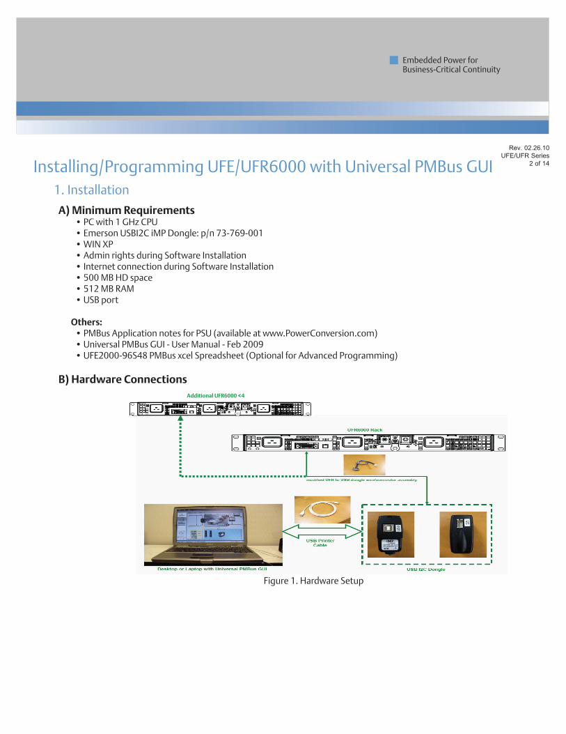
1. Installation
A) Minimum Requirements• PC with 1 GHz CPU• Emerson USBI2C iMP Dongle: p/n 73-769-001• WIN XP• Admin rights during Software Installation• Internet connection during Software Installation• 500 MB HD space• 512 MB RAM• USB port
Others:
• PMBus Application notes for PSU (available at www.PowerConversion.com)• Universal PMBus GUI - User Manual - Feb 2009• UFE2000-96S48 PMBus xcel Spreadsheet (Optional for Advanced Programming)
B) Hardware Connections
Installing/Programming UFE/UFR6000 with Universal PMBus GUI
Additional UFR6000 <4
Figure 1. Hardware Setup
Rev. 02.26.10UFE/UFR Series
3 of 14
Embedded Power for Business-Critical Continuity
313
process yellow
3405
1797
1375
116
2607
652
242
2985
375
240
1. Installation continued
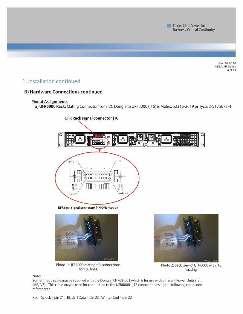
B) Hardware Connections continued
Pinout Assignments a) UFR6000 Rack: Mating Connector from I2C Dongle to URF6000 (J16) is Molex: 52316-2619 or Tyco: 2-5175677-4
UFR Rack signal connector J16
UFR rack signal connector PIN Orientation
Photo 1: UFR6000 mating = 3 connections for I2C lines
Photo 2: Back view of UFR6000 with J16 mating
Note:Sometimes a cable maybe supplied with the Dongle 73-769-001 which is for use with different Power Units (ref ; iMP/iVS). This cable maybe used for connection to the UFR6000 - J16 connection using the following color code references :
Red –Sclock = pin 21 , Black -SData = pin 23 , White- Gnd = pin 22
B) Hardware Connections continued
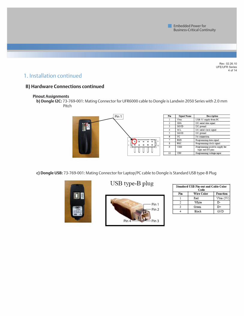
Pinout Assignments b) Dongle I2C: 73-769-001: Mating Connector for UFR6000 cable to Dongle is Landwin 2050 Series with 2.0 mm
Pitch
c) Dongle USB: 73-769-001: Mating Connector for Laptop/PC cable to Dongle is Standard USB type-B Plug
Rev. 02.26.10UFE/UFR Series
4 of 14
Embedded Power for Business-Critical Continuity
313
process yellow
3405
1797
1375
116
2607
652
242
2985
375
240
1. Installation continued
Pin 1
Rev. 02.26.10UFE/UFR Series
5 of 14
Embedded Power for Business-Critical Continuity
313
process yellow
3405
1797
1375
116
2607
652
242
2985
375
240
B) Hardware Connections continued
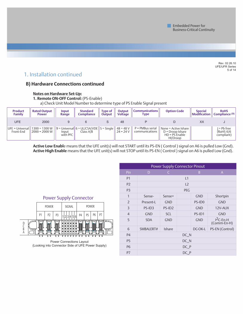
Notes on Hardware Set-Up:1. Remote ON-OFF Control: (PS-Enable) a) Check Unit Model Number to determine type of PS Enable Signal present
Active Low Enable means that the UFE unit(s) will not START until its PS-EN ( Control ) signal on A6 is pulled Low (Gnd).Active High Enable means that the UFE unit(s) will not STOP until its PS-EN ( Control ) signal on A6 is pulled Low (Gnd).
1. Installation continued
Product Family
UFE
UFE = UniversalFront-End
Input Range
9 = Universal Input
with PFC
Standard Compliance
6
6 = UL/CSA/VDE Class A/B
Rated Output Power
2000
1300 = 1300 W 2000 = 2000 W
Output Voltage
48
48 = 48 V 24 = 24 V
Type of Output
S
S = Single
Communications Type
C
P = PMBus serial communications
Special Modification
Option Code
None = Active IshareD = Droop IshareHD = PS Enable
HI/Droop
RoHS Compliance (9)
J
J = Pb free (RoHS 6/6 compliant)
UFE 2000 9 6 S 48 P D XX J
DCBA
POWER POWERSIGNAL
P1 P2 P3 P4 P5 P6 P71 2 53 64
Power Connections Layout(Looking into Connector Side of UFE Power Supply)
Power Supply Connector
Power Supply Connector Pinout
Pin D C B A
P1 L1
P2 L2
P3 PEG
1 Sense- Sense+ GND Shortpin
2 Present-L GND PS-ID0 GND
3 PS-ID3 PS-ID2 GND 12V-AUX
4 GND SCL PS-ID1 GND
5 SDA GND GND I2C-En-H(Comm-En-H)
6 SMBALERT# Ishare DC-OK-L PS-EN (Control)
P4 DC_N
P5 DC_N
P6 DC_P
P7 DC_P
Rev. 02.26.10UFE/UFR Series
6 of 14
Embedded Power for Business-Critical Continuity
313
process yellow
3405
1797
1375
116
2607
652
242
2985
375
240
B) Hardware Connections continued
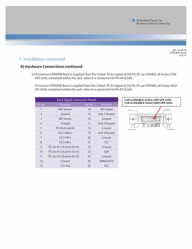
b) If Emerson UFR6000 Rack is supplied then the Global PS-En signal at J16 Pin #5 can ENABLE all Active LOW UFE Units contained within the rack when it is connected to Pin #4 (Gnd).
If Emerson UFR6000 Rack is supplied then the Global PS-En signal at J16 Pin #5 can DISABLE all Active HIGH
UFE Units contained within the rack when it is connected to Pin #4 (Gnd).
1. Installation continued
Rack Signal Connector Pinout
Pin No. Function Pin No. Function
1 48V Sense+ 14 48V Ishare
2 Ground 15 Unit 1 Present
3 48V Sense- 16 Ground
4 Ground 17 Unit 2 Present
5 PS-EN (Control) 18 Ground
6 DC1-OK0-L 19 Unit 3 Present
7 DC2-OK-L 20 Ground
8 DC3-OK-L 21 SCL
9 I2C-En-H-1 (Comm-En-H) 22 Ground
10 I2C-En-H-2 (Comm-En-H) 23 SDA
11 I2C-En-H-3 (Comm-En-H) 24 Ground
12 Ground 25 SMBALERT#
13 12V-Aux 26 N/C
Link to ENABLE Active LOW UFE Units Link to DISABLE Active HIGH UFE Units
Rev. 02.26.10UFE/UFR Series
7 of 14
Embedded Power for Business-Critical Continuity
313
process yellow
3405
1797
1375
116
2607
652
242
2985
375
240
B) Hardware Connections continued
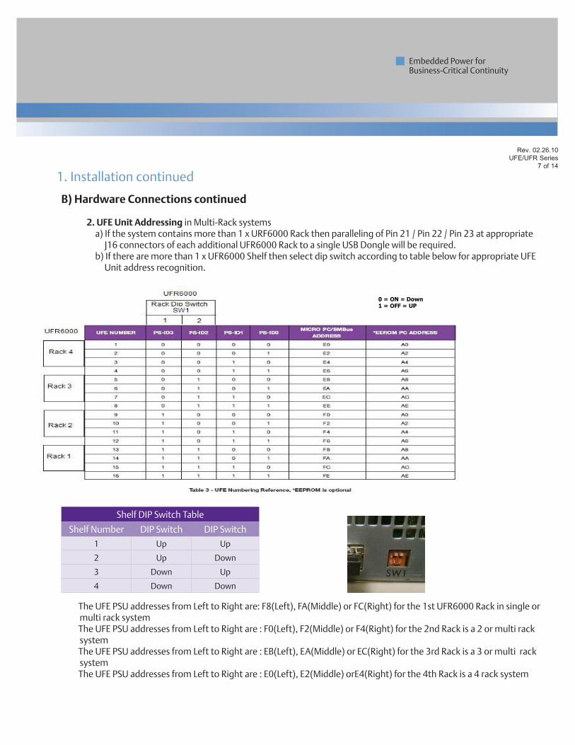
2. UFE Unit Addressing in Multi-Rack systems a) If the system contains more than 1 x URF6000 Rack then paralleling of Pin 21 / Pin 22 / Pin 23 at appropriate
J16 connectors of each additional UFR6000 Rack to a single USB Dongle will be required. b) If there are more than 1 x UFR6000 Shelf then select dip switch according to table below for appropriate UFE
Unit address recognition.
The UFE PSU addresses from Left to Right are: F8(Left), FA(Middle) or FC(Right) for the 1st UFR6000 Rack in single or multi rack system
The UFE PSU addresses from Left to Right are : F0(Left), F2(Middle) or F4(Right) for the 2nd Rack is a 2 or multi rack system
The UFE PSU addresses from Left to Right are : EB(Left), EA(Middle) or EC(Right) for the 3rd Rack is a 3 or multi rack system
The UFE PSU addresses from Left to Right are : E0(Left), E2(Middle) orE4(Right) for the 4th Rack is a 4 rack system
1. Installation continued
Shelf DIP Switch Table
Shelf Number DIP Switch DIP Switch
1 Up Up
2 Up Down
3 Down Up
4 Down Down
0 = ON = Down 1 = OFF = UP
Rev. 02.26.10UFE/UFR Series
8 of 14
Embedded Power for Business-Critical Continuity
313
process yellow
3405
1797
1375
116
2607
652
242
2985
375
240
C) Software Notes
1) Installation a) The Emerson Universal PMBus GUI requires a Software Framework/Platform in order to operate. The
preferred Framework is Microsoft .NET Framework 3.5. If not yet installed on your PC, download and install .Net 3.5 at http://www.microsoft.com/downloads/details.aspx?FamilyID=333325fd-ae52-4e35-b531- 508d977d32a6&DisplayLang=en
b) Create a Universal PMBus folder & extract contents of UniversalPMBusGUI_v00.09.00Beta_w-o_. NET3.5installer.zip to it. Universal PMBus GUI can be downloaded at this link http://www.powerconversion.com/pmbusgui
c) Inside Universal PMBus folder, run setup.exe d) Extract ail_HID_std.zip file in windows\system32 folder. This is the driver file for 73-769-001 USB I2C dongle. (Note : if your computer has a previous iMPGui installed then such can be found already).
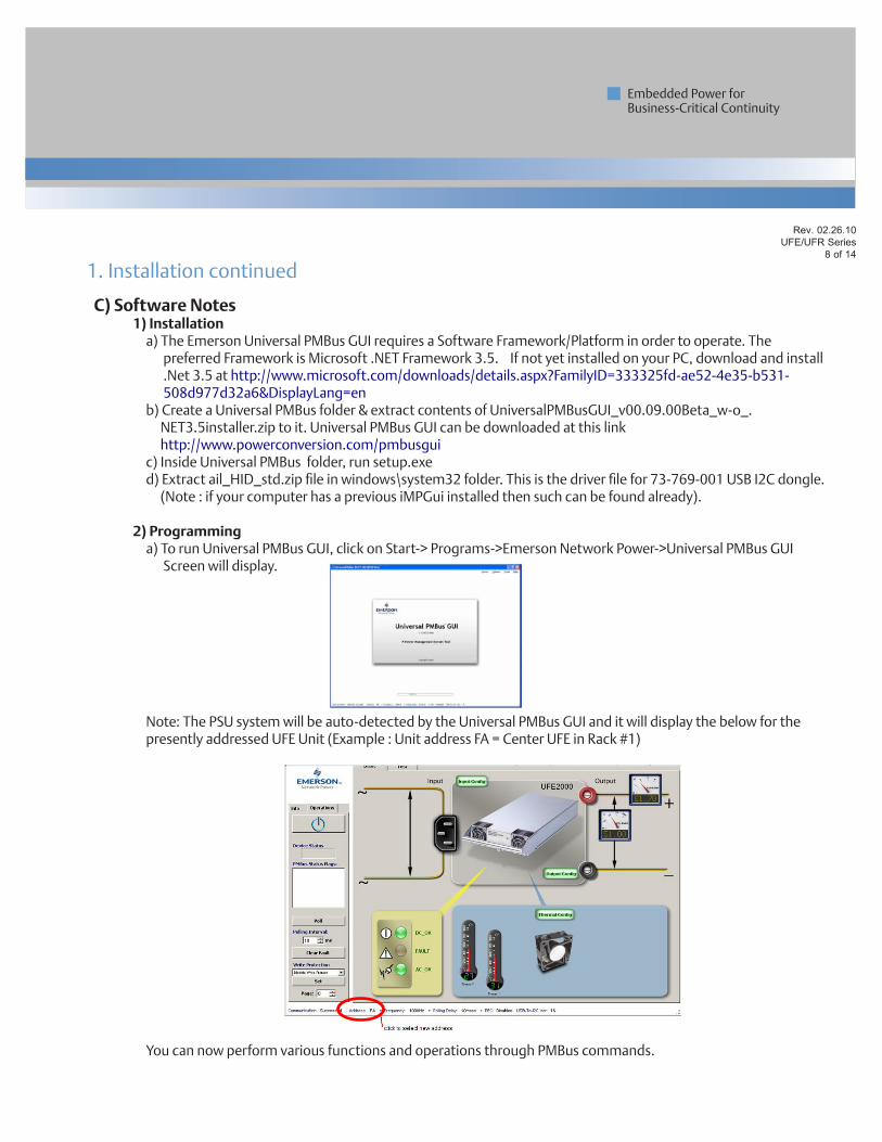
2) Programming a) To run Universal PMBus GUI, click on Start-> Programs->Emerson Network Power->Universal PMBus GUI
Screen will display.
Note: The PSU system will be auto-detected by the Universal PMBus GUI and it will display the below for the presently addressed UFE Unit (Example : Unit address FA = Center UFE in Rack #1)
You can now perform various functions and operations through PMBus commands.
1. Installation continued
Rev. 02.26.10UFE/UFR Series
9 of 14
Embedded Power for Business-Critical Continuity
313
process yellow
3405
1797
1375
116
2607
652
242
2985
375
240
C) Software Notes
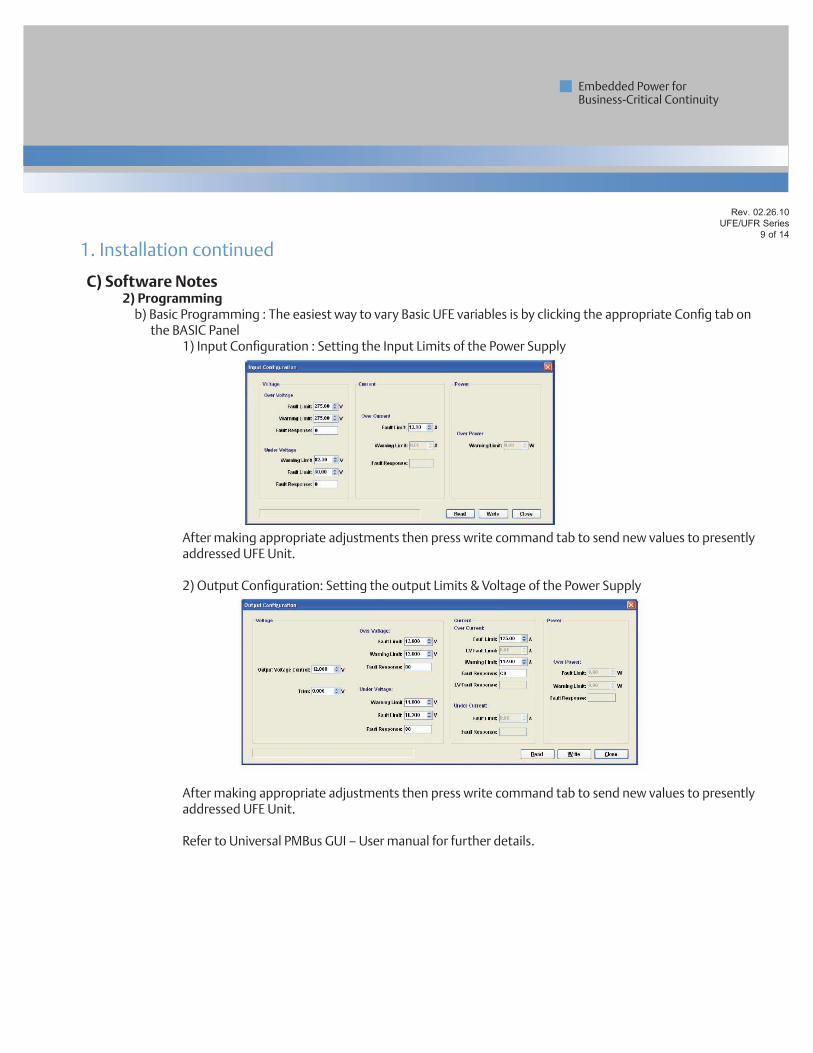
2) Programming b) Basic Programming : The easiest way to vary Basic UFE variables is by clicking the appropriate Config tab on
the BASIC Panel 1) Input Configuration : Setting the Input Limits of the Power Supply
After making appropriate adjustments then press write command tab to send new values to presently addressed UFE Unit.
2) Output Configuration: Setting the output Limits & Voltage of the Power Supply
After making appropriate adjustments then press write command tab to send new values to presently addressed UFE Unit.
Refer to Universal PMBus GUI – User manual for further details.
1. Installation continued
Rev. 02.26.10UFE/UFR Series
10 of 14
Embedded Power for Business-Critical Continuity
313
process yellow
3405
1797
1375
116
2607
652
242
2985
375
240
C) Software Notes
2) Programming b) Basic Programming : The easiest way to vary Basic UFE variables is by clicking the appropriate Config tab on
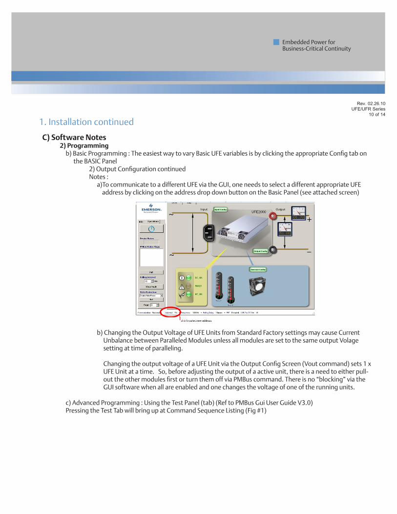
the BASIC Panel 2) Output Configuration continued Notes : a)To communicate to a different UFE via the GUI, one needs to select a different appropriate UFE
address by clicking on the address drop down button on the Basic Panel (see attached screen)
b) Changing the Output Voltage of UFE Units from Standard Factory settings may cause Current Unbalance between Paralleled Modules unless all modules are set to the same output Volage setting at time of paralleling.
Changing the output voltage of a UFE Unit via the Output Config Screen (Vout command) sets 1 x UFE Unit at a time. So, before adjusting the output of a active unit, there is a need to either pull- out the other modules first or turn them off via PMBus command. There is no “blocking” via the GUI software when all are enabled and one changes the voltage of one of the running units.
c) Advanced Programming : Using the Test Panel (tab) (Ref to PMBus Gui User Guide V3.0) Pressing the Test Tab will bring up at Command Sequence Listing (Fig #1)
1. Installation continued
Rev. 02.26.10UFE/UFR Series
11 of 14
Embedded Power for Business-Critical Continuity
313
process yellow
3405
1797
1375
116
2607
652
242
2985
375
240
C) Software Notes
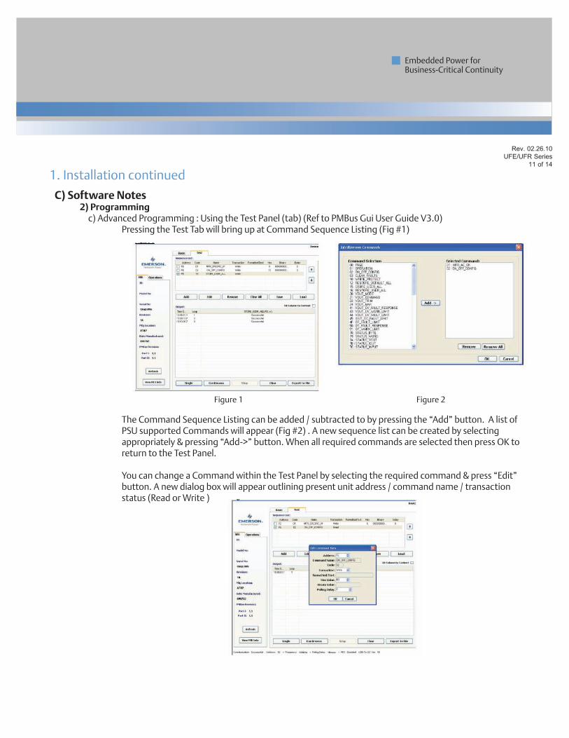
2) Programming c) Advanced Programming : Using the Test Panel (tab) (Ref to PMBus Gui User Guide V3.0) Pressing the Test Tab will bring up at Command Sequence Listing (Fig #1)
The Command Sequence Listing can be added / subtracted to by pressing the “Add” button. A list of PSU supported Commands will appear (Fig #2) . A new sequence list can be created by selecting appropriately & pressing “Add->” button. When all required commands are selected then press OK to return to the Test Panel.
You can change a Command within the Test Panel by selecting the required command & press “Edit” button. A new dialog box will appear outlining present unit address / command name / transaction status (Read or Write )
1. Installation continued
Figure 1 Figure 2
Rev. 02.26.10UFE/UFR Series
12 of 14
Embedded Power for Business-Critical Continuity
313
process yellow
3405
1797
1375
116
2607
652
242
2985
375
240
C) Software Notes
2) Programming c) Advanced Programming : Notes : a) The commands in the sequence list view are Read Transactions by default but can be selected to
Write via the “down” arrow. b) The appropriate Hex Code needs to be entered followed by “OK” button. The Hex Code is developed from the UFE2000-96S48 PMBus excel Spread sheet The excel spreadsheet has macros which will not run unless you enable such. When opening the spreadsheet, one needs to enable macros when asked and also verify that
the Analysis Tool Pak in excel is active. This is achieved by checking excel under Tools->Add-in options.
If such are not enabled then when you change the values in the command spreadsheet, the resultant value/s will not change
c) Pressing the “Single” or “Continuous” button executes the new command d) The Test Panel allows you to connect to multiple UFE Units because the Address Column is
changeable per command. You can also arrange the command sequence, save & load it for future use.
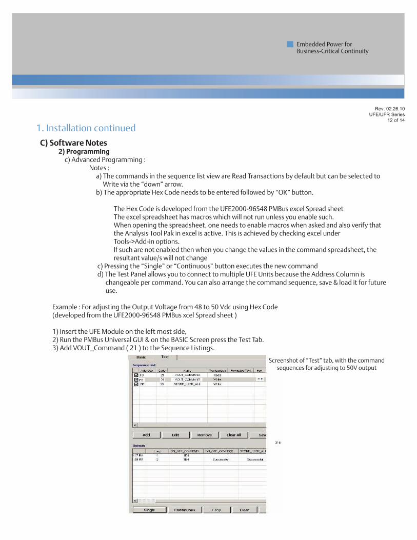
Example : For adjusting the Output Voltage from 48 to 50 Vdc using Hex Code (developed from the UFE2000-96S48 PMBus xcel Spread sheet ) 1) Insert the UFE Module on the left most side,2) Run the PMBus Universal GUI & on the BASIC Screen press the Test Tab.3) Add VOUT_Command ( 21 ) to the Sequence Listings.
1. Installation continued
Screenshot of “Test” tab, with the command sequences for adjusting to 50V output
Rev. 02.26.10UFE/UFR Series
13 of 14
Embedded Power for Business-Critical Continuity
313
process yellow
3405
1797
1375
116
2607
652
242
2985
375
240
C) Software Notes
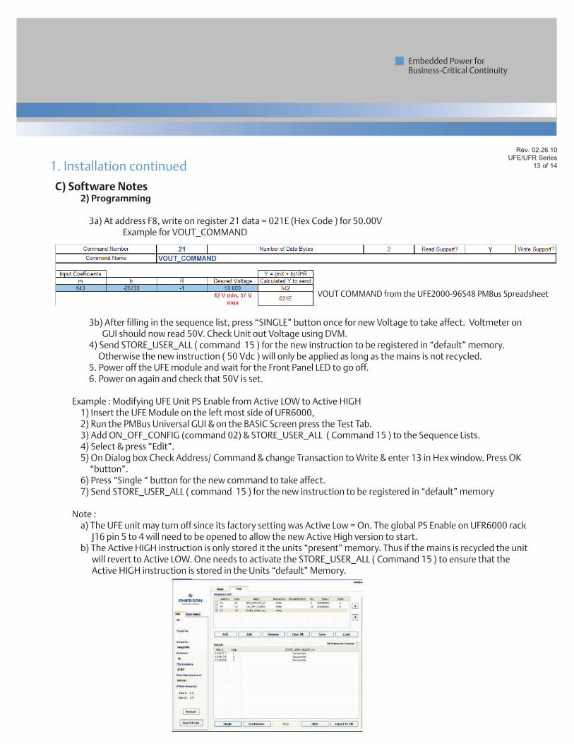
2) Programming 3a) At address F8, write on register 21 data = 021E (Hex Code ) for 50.00V Example for VOUT_COMMAND
3b) After filling in the sequence list, press “SINGLE” button once for new Voltage to take affect. Voltmeter on GUI should now read 50V. Check Unit out Voltage using DVM.
4) Send STORE_USER_ALL ( command 15 ) for the new instruction to be registered in “default” memory. Otherwise the new instruction ( 50 Vdc ) will only be applied as long as the mains is not recycled.
5. Power off the UFE module and wait for the Front Panel LED to go off. 6. Power on again and check that 50V is set.
Example : Modifying UFE Unit PS Enable from Active LOW to Active HIGH 1) Insert the UFE Module on the left most side of UFR6000, 2) Run the PMBus Universal GUI & on the BASIC Screen press the Test Tab. 3) Add ON_OFF_CONFIG (command 02) & STORE_USER_ALL ( Command 15 ) to the Sequence Lists. 4) Select & press “Edit”. 5) On Dialog box Check Address/ Command & change Transaction to Write & enter 13 in Hex window. Press OK
“button”. 6) Press “Single “ button for the new command to take affect. 7) Send STORE_USER_ALL ( command 15 ) for the new instruction to be registered in “default” memory
Note : a) The UFE unit may turn off since its factory setting was Active Low = On. The global PS Enable on UFR6000 rack
J16 pin 5 to 4 will need to be opened to allow the new Active High version to start. b) The Active HIGH instruction is only stored it the units “present” memory. Thus if the mains is recycled the unit
will revert to Active LOW. One needs to activate the STORE_USER_ALL ( Command 15 ) to ensure that the Active HIGH instruction is stored in the Units “default” Memory.
1. Installation continued
VOUT COMMAND from the UFE2000-96S48 PMBus Spreadsheet
Embedded Power for Business-Critical Continuity
Rev. 02.26.10UFE/UFR Series
14 of 14
Embedded Power for Business-Critical Continuity
313
process yellow
3405
1797
1375
116
2607
652
242
2985
375
240
Americas 5810 Van Allen WayCarlsbad, CA 92008USATelephone: +1 760 930 4600Facsimile: +1 760 930 0698
Europe (UK)Waterfront Business ParkMerry Hill, DudleyWest Midlands, DY5 1LXUnited KingdomTelephone: +44 (0) 1384 842 211Facsimile: +44 (0) 1384 843 355
Asia (HK)14/F, Lu Plaza2 Wing Yip StreetKwun Tong, KowloonHong KongTelephone: +852 2176 3333Facsimile: +852 2176 3888 For global contact, visit:www.PowerConversion.com
While every precaution has been taken to ensure accuracy and completeness in this literature, Emerson Network Power assumes no responsibility, and disclaims all liability for damages resulting from use of this information or for any errors or omissions.
Emerson Network Power and the Emerson Network Power logo are trademarks and service marks of Emerson Electric Co. ©2010 Emerson Electric Co.
EmersonNetworkPower.com
Embedded Computing
Embedded Power
Monitoring
Outside Plant
Power Switching & Controls
Precision CoolingRacks & Integrated Cabinets
Services
Surge Protection
Emerson Network Power. The global leader in enabling business-critical continuity.
AC Power
Connectivity
DC Power