Embed Size (px)
Citation preview

Technical Reference ManualLFXG®FiberFlex® Detector with GEN2000®
Electronics for Level Measurement
Document ID:31401
Nuclear


Revision history
Table 1: Revision history
Version Description Date
1.0 Initial release. Formerly 240694. 051201
1.1 Electronics Revision 090309
1.2 Added certification information and IECex label 090819
1.3 Changed company name, logo, and website 110301
Copyright© 2011 VEGA Americas, Inc., Cincinnati, Ohio. All rights reserved.
This document contains proprietary information of VEGA Americas, Inc. It shall not be reproduced in whole or in part, in any form, without the expressed written permission of VEGA Americas, Inc.
The material in this document is provided for informational purposes and is subject to change without notice.
FiberFlex is a registered trademark of the VEGA Americas, Inc.
VEGAView and Ohmview 2000 are registered trademarks of the VEGA Americas, Inc.
HART® is a registered trademark of The HART® Communication Foundation.
ISO 9001 approval by Lloyd’s Register Quality Assurance Limited, to the following Quality Management System Standards: ISO 9001:2000, ANSI/ASQC Q9001-2000, Approval Certificate No. 107563.
VEGA Americas, Inc.
4170 Rosslyn Drive
Cincinnati, Ohio 45209-1599 USA Voice:
( 5 1 3 ) 2 7 2 - 0 1 3 1 FAX:
( 5 1 3 ) 2 7 2 - 0 1 3 3 Web site www.vega-americas.com
WARNING
Use this equipment only in the manner that this manual describes. If you do not use the
equipment per VEGA specifications, the unit is not CE compliant, and may be damaged or
cause personal injury.

Preface
ii LFXG-H Technical Reference Manual
NOTES

Preface
LFXG-H Technical Reference Manual iii
Contents
Table 1: Revision history i Contents iii Explanation of symbols xii Table 2: Explanation of symbols xii
HART software screens xiv Figure 1: HART screen—gauge not connected xiv Figure 2: HART screen—gauge connected xv
Your comments xvi
Chapter 1 : Introduction 1
Nuclear materials notice 1 Unpacking the equipment 2 Storing the equipment 3
Storing the source holder 3 Storing the detector 3
Certifications 3 Safety Information for EX Areas 4 Figure 3: IECex Label 4
LFXG-H specifications 5 Table 3: LFXG-H specifications 5
Typical applications 6 Pulp and Paper 6 Chemical 6 Food and beverage 6 Water and wastewater 6
Where to find help 7 VEGA Customer Service 7 Table 4: Contact information 7 Principle of operation 8 System overview 8 Figure 4: System overview 8 Figure 5: Typical source holder 9 Scintillator model LFXG-H 10 Figure 6: LFXG-H exploded view 10
Communicating with the gauge 11 Using a universal hand-held terminal 11 Figure 7: HART hand-held communicator 12 Using VEGA View software on a PC 13 Figure 8: VEGA View software 13 Using Ohmview 2000 Software on a PC 15 Figure 9: Ohmview 2000 software 15 Figure 10: Example of an Ohmview 2000 CD label 16
The HART screens menu structure 17 Figure 11: Online menu 17
Chapter 2 : Installation 19
Testing on the bench 19 Figure 12: Bench test setup 19
Location considerations 20 Stable temperature 20 Protect insulation 20 Avoid internal obstructions 20

Preface
iv LFXG-H Technical Reference Manual
Avoid external obstructions 21 Avoid source cross-talk 21
Mounting the measuring assembly 22 Figure 13: Conduit and bracket mounting 22
Wiring the equipment 23 Figure 14: LFXG-H internal and external ground screw 23 Figure 15: Interconnect 24 Table 5: Terminal names and descriptions 24 Power 25 Switch for CE compliance 25 Output current loop 25 Communication 26 Process alarm override switch 26 Conduit 26
Commissioning the gauge 27 Can you remove the source holder lock? 27 Field service commissioning call checklist 30
Chapter 3 : Calibration 31
Current loop (analog output) calibration 32 Figure 16: Measuring the current loop output 32 Calibrating the current loop 33 Procedure 1: Calibrating the current loop 33
Choosing the calibration method 34 Table 6: Calibration methods 34
Standard method of calibration 35 Figure 17: Standard method calibration flow chart 35 Table 7: Standard method calibration 36
Simple method of calibration 37 Figure 18: Simple method calibration flow chart 37 Table 8: Simple method calibration 38
Theory of calibration 39 Both calibration methods 39 Both calibration methods 39 Standard calibration method 39 Figure 19: Linearizer data collected at various process levels 39 Simple calibration method 40 Standard calibration method 40 Simple calibration method 40 Figure 20: Raw counts vs. actual level with linearizers 40 Standard calibration method 40 Simple calibration method 40 Figure 21: %Count range vs. %span (shown in linearizer table) 41 Both calibration methods 41 Figure 22: Indicated level vs. actual level 41
Choosing the linearizer type 42 Non-linear table 42 Table, linear 42 Choosing a linearizer method 43 Procedure 2: Choosing a linearizer method 43 Checking the gauge repeatability 43 Performing a data collect 44 Procedure 3: Performing a data collect 44
Calibrating the gauge 44 Table 9: Standard calibration sensor counts and levels record 45

Preface
LFXG-H Technical Reference Manual v
Step 1: Set low level 46 Setting the cal low level 46 Procedure 4: Setting the cal low level 46 Step 2: Set high level 47 Setting the cal high level 47 Procedure 5: Setting the cal high level 47 Step 3: Collecting linearizer table data 48 Collecting linearizer table data 48 Procedure 6: Collecting linearizer table data 48 Step 4: Calculating the linearity 49 Calculating a new linearizer table 49 Procedure 7: Calculating the linearizer 49 Step 5: Calculate calibration 50 Calculating the calibration result 50 Procedure 8: Calculating the calibration result 50
When a new calibration may be necessary 51 Periodic process standardization 51 Automatic standardization reminder 51 Performing a standardization 52 Standardizing the gauge 52 Procedure 9: Standardizing the gauge 52
Chapter 4 : Advanced functions 53
Process chain 53 Primary channel 53 Temp 53 Sensor cnts 53 TC counts 53 Raw counts 53 Adj counts 54 SD counts 54 Stdz counts 54 % Cnt range 54 % of span 54 Figure 23: % counts range vs. % process span 54 Raw level 55 Uncomp Lvl 55 Level 55 Process variables 55 Counts low 55 Counts high 55 Max level 55 Min level 55 Temp comp gain 55 Uniformity gain 55 Source decay gain 55 Stdz gain 55 HV setting 56 Aux channel chain 56 Aux raw counts 56 Filt counts 56
Min/Max history 56 Temp min/max 56 Sensor min/max 56 Aux in min/max 56
Preface
vi LFXG-H Technical Reference Manual
Last reset 56 Resetting the minimum and maximum history 57 To reset the minimum and maximum history 57 Procedure 10: Resetting the minimum and maximum history 57
New hardware or EEPROM corrupt 58 Proper response to "New hardware found" message if new hardware has been installed 59 If a new CPU board has been installed 59 Procedure 11: New Hardware Found message with new CPU board 59 Proper response to "New hardware found" message if new hardware has not been installed 59 CPU EEPROM Corrupt message or Sensor EEPROM Corrupt message 59 To repair the corruption from the EEPROM backup 60 Procedure 12: Repairing corrupted EEPROM 60
Test modes 61 Milliamp output test mode 61 Start milliamp output test mode 62 Procedure 13: Start mA output test mode 62 Exit milliamp output test mode 62 Procedure 14: Exit mA output test mode 62 Sensor test mode 63 Start sensor test mode 64 Procedure 15: Start Sensor test mode 64 Exit sensor test mode 64 Procedure 16: Exit Sensor test mode 64 Auxiliary input test mode 65 Start auxiliary input test mode 65 Procedure 17: Start Auxiliary test mode 65 Exit auxiliary input test mode 65 Procedure 18: Exit Auxiliary test mode 65 Relay test mode 66 Start relay test mode 66 Procedure 19: Start Relay test mode 66 Exit relay test mode 66 Procedure 20: Exit Relay test mode 66 Temperature test mode 67 Procedure 21: Start Temperature test mode 67 Exit temperature test mode 67 Procedure 22: Exit Temperature test mode 67
Other advanced functions 68 Checking the sensor voltage, poll address, equipment version, serial numbers, and temperature coefficients 68 Sensor voltage 68 Poll address 68 Firmware version 68 Hardware version 68 CPU Serial Number 68 Sensor Serial Number 68 View temperature coefficients 68 Checking the sensor voltage, poll address, version, and serial numbers 69 Procedure 23: Checking equipment version and serial numbers 69
Select gauge type 70 Procedure 24: Select gage type 70
Select gauge location 70 Procedure 25: Select gage location 70

Preface
LFXG-H Technical Reference Manual vii
Chapter 5 : Diagnostics and repair 71
Software diagnostics 71
Alarms 72 Table 10: Alarm type summary 72
Diagnostic 73 History information 74 Summary of diagnostic alarm conditions 75 Table 11: Diagnostic alarm conditions 75 Procedure 26: Viewing and acknowledging diagnostic alarms 76
Analog 77 Process 77 X-ray 78
Auxiliary x-ray alarm system 78 Figure 24: X-ray interference alarm output 78
Hardware diagnostics 79 Figure 25: GEN2000 circuit boards 79 Figure 26: GEN2000 circuit board components - simplified 80 Test points 80 Table 12: Power supply board test point labels and descriptions 80 Table 13: CPU test point labels and descriptions 80 Jumpers 81 Table 14: Jumper settings 81 LED indicators 82 Figure 27: LED indicators 82 FLASH corrupt LED pattern 83 Table 15: Power supply board LED summary 83 Power Supply Board LED summary table 83 CPU Board LED summary table 84 Table 16: CPU board LED summary 84
Troubleshooting 85 Communication problem flowchart 86 Figure 28: Communication problem flowchart 86 Transmitter not responding flowchart – part 1 87 Figure 29: Transmitter not responding flowchart – Part 1 87 Transmitter not responding flowchart – part 2 88 Figure 30: Transmitter not responding flowchart – part 2 88
Maintenance and repair 89 Periodic maintenance schedule 89 Table 17: Periodic maintenance schedule 89 Source wipe and shutter check recording 89 Recording a source wipe or shutter check 89 Procedure 27: Recording a source wipe or shutter check 89 Check when the next source wipe or shutter check is due 90 Procedure 28: Check due date of source wipe or shutter check 90 Spare parts 90
Field repair procedures 91 Replacing the CPU or Power supply board 92 Replace the CPU or Power supply board 93 Procedure 29: Replacing the CPU or power supply board 93 Requesting field service 94 Returning equipment for repair to VEGA 94 Returning equipment for repair 95 Procedure 30: Returning equipment for repair 95
Appendix I: Initial factory setup 97

Preface
viii LFXG-H Technical Reference Manual
Process parameters 98 Units 98 Level units 98 Custom units 98 Setting the process units 98 Procedure 31: Setting the process units 98 Setting custom units 99 Procedure 32: Setting custom units 99 Calibration parameters 99 Data coll interval 99 Warn % span cal 99 Process stdz type 100 Default std 100 Stdz interval 100 Setting the calibration parameters 100 Procedure 33: Setting the calibration parameters 100
Filtering 101 Type (RC exponential or rectangular window) 101 RC exponential 101 Figure 31: RC exponential filtering 101 Rectangular window filtering 102 Figure 32: Rectangular window filtering 102 Damping 102 Fast response cutoff 102 Selecting a filter type, damping, and fast cutoff 103 Procedure 34: Selecting a filter type, damping, and fast cutoff 103 Span settings 104 Process span 104 Setting process span 104 Procedure 35: Setting the process span 104 Current loop span 105 Table 18: Setting process values of 0% and 100% 105 Procedure 36: Setting the current loop span 105
System parameters 106 Time 106 Date 106 Setting the time and date 106 Procedure 37: Setting the time and date 106 Source type 107 Procedure 38: Setting the source type 107 Source function 107 Wipe Interval 107 Record wipe 107 Shut chk Interval 107 Record shut chk 108
Next wipe/Shut due 108
Tag 108 Setting the tag identifier 108 Procedure 39: Setting the tag identifier 108 System information 109 Message 109 Procedure 40: Setting the system information message 109 Descriptor 109 Procedure 41: Setting the descriptor 109
Setting up alarms 110

Preface
LFXG-H Technical Reference Manual ix
Diagnostic alarm setup 111 Table 19: Diagnostic alarm conditions 111 Setting the diagnostic alarm conditions 112 Procedure 42: Setting the relay as a diagnostic alarm 112 Setting the relay as a diagnostic alarm 112 Procedure 43: Setting the diagnostic alarm conditions 112 Analog alarm setup 113 Table 20: Analog alarm conditions 113 Setting the analog alarm output 113 Procedure 44: Setting the analog alarm output 113 Process alarm setup 114 Table 21: Process relay set alarm conditions 114 Setting up the process alarm 115 Procedure 45: Setting up the process alarm 115 X-ray alarm setup 116 Figure 33: X-ray interference alarm output 116 Threshold 116 Dither level 116 Cycle period 116 Dither time 117 Table 22: X-ray alarm conditions 117 Setting up the x-ray alarm parameters 117 Procedure 46: Setting up the x-ray alarm parameters 117 Setting the relay as an x-ray alarm 118 Procedure 47: Setting the relay as an x-ray alarm 118
Auxiliary input settings 119 Input filter 119 Setting the auxiliary input filter 120 Procedure 48: Setting the input filter 120
Appendix II: Special applications 121
Multiple detectors summation 122 Figure 34: Multiple detectors summation 122 Special drawings from VEGA 123 Notes on the frequency output detector 123 LFXG-F spare parts 124 Table 23: LFXG-F spare parts 124 Installation requirements 124 Figure 35: Placement of multiple detectors 125 Detector wiring 126 Figure 36: Interconnect—Multiple detector 126 Figure 37: Multiple detector interconnect terminals 127 Initial settings and calibration requirements 128 Table 24: Initial setting and calibration locations 128 Setting up summation mode 129 Procedure 49: Setting up summation mode 129 Calibrating with multiple detectors summation 129
NORM (naturally occurring radioactive material) compensation 130 Figure 38: NORM compensation system 130 Special drawings for NORM Compensation 131 Installation requirements 132 Figure 39: Placement of detectors for NORM compensation 132 Detector wiring 132 Figure 40: Interconnect— LFXG-F with LFXG-H 133 Figure 41: Dual detector interconnect terminals 134

Preface
x LFXG-H Technical Reference Manual
Initial settings and calibration requirements for NORM compensation 135 Setting up NORM compensation 135 Procedure 50: Setting up NORM compensation 135 Calibrating with NORM compensation 136 Procedure 51: Calibrating with NORM compensation 137
GEN2000 Local RS-485 Network 138 Installation requirements 139 Figure 42: Typical installation—vapor compensation & auto zero 139 Detector wiring 140 Figure 43: Interconnect—GEN2000 RS-485 multiple detectors/transmitters 140 Software 141 Figure 44: Ohmview 2000 Launcher program 141 Figure 45: Ohmview 2000 RS-485 main screen 142 Figure 46: RS-485 Master Main menu screen 143 Responder Gauge Data 144 Figure 47: RS-485 Responder gauge data screen 144 Responder Function 145 Figure 48: RS-485 Responder Function screen 145 Figure 49: Responder function pull-down menu 146 Procedure 52: Changing the Responder unit function 146 Communication Statistics 147 Figure 50: RS-485 Communication Statistics screen 147 Master Configuration 148 Figure 51: RS-485 Master Configuration screen 148 Responder Main menu 149 Procedure 53: Connecting directly to a Responder 149 Figure 52: Responder Main Screen 149 Initial setup 150 Procedure 54: Setting up GEN2000 RS-485 local network 150 Procedure 54: Setting up GEN2000 RS-485 local network (continued) 151 Procedure 54: Setting up GEN2000 RS-485 local network (continued) 151
Auto Zero feature 153 Setting up the Auto Zero feature 153 Procedure 55: Setting up GEN2000 RS-485 local network 154 Procedure 55: Setting up GEN2000 RS-485 local network (continued) 155
Vapor pressure compensation 156 Figure 53: Vapor compensation system 156 Installation requirements 157 Detector wiring 157 Figure 54: Interconnect DSGH with LFXG-H 157 Algorithm for vapor comp 158 Variable definitions 158
Reference counts 158 Vapor density counts 158 VC gain 158
Initial settings and calibration for vapor comp 159 Setting up vapor compensation 159 Procedure 56: Setting up vapor compensation 159 Calibrating with vapor compensation 160 Calibrating with vapor compensation 160 Procedure 57: Calibrating with vapor compensation 160 Procedure 55: Calibrating with vapor compensation (continued) 161
Internal heater kit for applications requiring a –50 C rating 162 Table 25: Heater kit part numbers 162 Changes to specifications 162

Preface
LFXG-H Technical Reference Manual xi
Appendix III: Preserving information from SmartPro to the LFXG-H 163
Preserving information from SmartPro 163 Table 26: Smart Pro data record 164 Table 27:Linearizer record 165 Table 33: Linearizer record (continued) 166
Appendix IV: HART menus and screens 167
Figure 55: HART screen—Transmitter not connected 168 Figure 56: HART screen—Online 169 Figure 57: Initial setup 170 Figure 58: Process parameters 171 Figure 59: System parameters 172 Figure 60: Alarms 173 Figure 61: Auxiliary input 174 Figure 62: View settings 175 Figure 63: Calibrations 176 Figure 64: Initial cal 177 Figure 65: Process stdz 178 Figure 66: Data collect 178 Figure 67: Current loop Cal 178 Figure 68: Linearizer 179 Figure 69: Gauge status 180 Figure 70: Advanced Fxns 181 Figure 71: Process chain 182 Figure 72: Min/max history 183 Figure 73: New hardware 184 Figure 74: Test mode 185 Figure 75: Other advanced 186 Figure 76: Select gage type 187 Figure 77: Select gage location 187

Preface
xii LFXG-H Technical Reference Manual
Explanation of symbols Table 2 lists the symbols that the manual and instrument use.
Table 2: Explanation of symbols
Radiation notice
In the manual, information concerning radioactive materials or radiation safety information is found in the accompanying text.
Caution! The text next to this symbol contains the warning of potential damage to equipment or people.
Attention! Le texte apparaissant près de ce symbole vous informe d’un danger possible pour l’équipement ou pour l’usager.
AC current or voltage
On the instrument, a terminal to which or from which an alternating (sine wave) current or voltage may be applied or supplied.
DC current or voltage
On the instrument, a terminal to which or from which a direct current voltage may be applied or supplied.
Potentially hazardous voltages
On the instrument, a terminal on which potentially hazardous voltage exists.

Preface
LFXG-H Technical Reference Manual xiii
Notes
Preface
xiv LFXG-H Technical Reference Manual
HART software screens
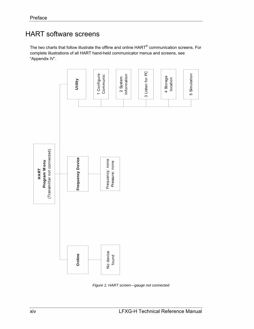
The two charts that follow illustrate the offline and online HART® communication screens. For complete illustrations of all HART hand-held communicator menus and screens, see “Appendix IV”.
On
lin
e
No
de
vice
fou
nd
Uti
lity
Fre
qu
en
cy D
ev
ice
2 S
yste
mIn
form
atio
n
3 L
iste
n f
or
PC
HA
RT
Pro
gra
m M
en
u(T
ran
smit
ter
no
t co
nn
ect
ed
)
5 S
imu
lati
on
4 S
tora
ge
loca
tio
n
1 C
on
fig
ure
Co
mm
un
icFr
eq
ue
ncy
: n
on
eP
ress
ure
: n
on
e
Figure 1: HART screen—gauge not connected

Preface
LFXG-H Technical Reference Manual xv
3 M
ain
men
u1
Lev
el
##
.##
%#
#.#
# m
A
2 C
ur
ou
t
1 In
itia
l set
up
2 C
alib
rati
ons
3 G
auge
sta
tus
4 A
dvan
ced
Fxns
HA
RT
scre
en f
eatu
res
(Tra
nsm
itte
r con
nect
ed)
Figure 2: HART screen—gauge connected

Preface
xvi LFXG-H Technical Reference Manual
Your comments
VEGA values your opinion! Please fill out this page so that we can continually improve our technical documentation.
Manual: LFXG-H Technical Reference Manual
Date: ______________
Customer Order Number: ___________________
How we can contact you (optional if you prefer to remain anonymous):
Name: _________________________
Title: _________________________
Company: __________________________
Address: __________________________
__________________________
__________________________
Did you find errors in this manual? If so, specify the error and page number.
Did you find this manual understandable, usable, and well organized? Please make suggestions for improvement.
Was information you needed or would find helpful not in this manual? Please specify.
Please send this page to:
VEGA Americas, Inc. Director of Engineering 4241 Allendorf Drive Cincinnati, OH 45209-1599

Preface
LFXG-H Technical Reference Manual xvii
Notes


LFXG-H Technical Reference Manual 1
Chapter 1: Introduction
Nuclear materials notice
This equipment contains radioactive source material that emits gamma radiation. Gamma radiation is a form of high-energy electromagnetic radiation. Only persons with a specific license from the U.S. NRC (or other regulating body) may perform the following to the source holder:
Dismantle
Install
Maintain
Relocate
Repair
Test
VEGA Field Service engineers have the specific license to install and commission nuclear gauges, and can instruct you in the safe operation of your level gauge. To contact VEGA Field Service, call 513-272-0131. Users outside the U.S. and Canada may contact their local representative for parts and service.
Note: Special instructions concerning your source holder are found in the envelope that was shipped with the source holder and the “Radiation Safety for U.S. General and Specific Licensees, Canadian, and International Users” manual and the “Radiation Safety Manual Addendum of Reference Information” CD. Please refer to this document for radiation safety information.

Introduction
2 LFXG-H Technical Reference Manual
Unpacking the equipment
CAUTION!
Make sure that you are familiar with radiation safety practices in accordance with your U.S. Agreement State, U.S. NRC, or your country’s applicable regulations before unpacking the equipment.
Unpack the unit in a clean, dry area
Inspect the shipment for completeness, by checking against the packing slip
Inspect the shipment for damage during shipment or storage
If the detector is included as a separate package in the shipment, inspect the assembly for damage that may have occurred during shipment or storage
If there was damage to the unit during shipment, file a claim against the carrier, reporting the damage in detail. Any claim on the VEGA for shortages, errors in shipment, etc., must be made within 30 days of receipt of the shipment
If you need to return the equipment, see the section “Returning equipment for repair to VEGA” in the “Diagnostics and Repair” chapter
After you unpack the equipment, inspect each source holder in the shipment to assure that the operating handle is in the OFF position. In the event that you find the handle in the ON position, place it in the OFF position immediately and secure it.
Note: Most source holder models accept a lock. Call VEGA Field Service immediately for further instructions, at 513-272-0131, if the source holder has one of the following conditions:
Does accept a lock and there is no lock on it
The lock is not secured
You are unable to secure the lock
The operating handle does not properly move into the off position

Introduction
LFXG-H Technical Reference Manual 3
Note: Low activity source holders have different requirements than the typical source holders. For example, since they usually do not have shutters – the shutter check test is not required. Contact VEGA for further information regarding the low activity source holders.
Storing the equipment
Storing the source holder If it is necessary to store the source holder, do so in a clean, dry area. Be sure the source holder shutter is in the OFF or CLOSED position. Check the current local regulations (U.S. NRC, Agreement State, or other) to determine if this area must have any restrictions.
Storing the detector Avoid storage at temperatures below freezing. Store the detector indoors in an area that has temperature-control between +10 C and +35 C (+50 F and +95 F) and less than 50% relative humidity. Store equipment in dry conditions until installation.
Certifications
This gauge is designed for certi�cation compliance from the following agencies:
ATEX Standard
CCOE (India)
CEPEL/INMETRO (Brazil)
CSA
FM Standard
GOST-B Standard
GOST-R Standard
IECex
JIS (Japan)
KTL (Korea)
NEPSI (China)

Introduction
4 LFXG-H Technical Reference Manual
MAR 2000
MODEL: GEN2000 TM
CONTACT RATINGS:240VAC, 2A, OR 24VDC, 2A, OR 1/4HP @ 120VAC
Ex d IIC T6 Ta = -20°C TO +60°C OR
Patent No. 6,198,103
IP66Ex d IIB+H2 T6 Ta = -50°C TO +60°C,
IECEx CSA 09.0005X
CINCINNATI, OHIO U.S.A. 45209
INPUT:115V , 25 W, 50/60 Hz
WARNING: USE A CABLE OR WIRING RATED FOR AT LEAST 90° CWARNING: POTENTIAL ELECTROSTATIC CHARGING HAZARD - SEE INSTRUCTIONSWARNING: DO NOT OPEN WHEN AN EXPLOSIVE ATMOSPHERE MAY BE PRESENT
2478
61
Safety Information for EX Areas Please note the EX-speci�c safety information for installation and operation in EX areas.
Figure 3: IECex Label

Introduction
LFXG-H Technical Reference Manual 5
LFXG-H specifications
Table 3: LFXG-H specifications
System Accuracy 1% of span typical Accuracy depends on specific application parameters
Active Lengths Flexible detector 305–7,010mm (12–276”) in 305mm (12”) increments
Typical Sources Cesium-137 0.66MeV gamma radiation emitter, 30.2 year half life
Cobalt-60 1.2 & 1.3MeV gamma radiation emitter, 5.3 year half life
Power Requirements*
AC 100–230 10% VAC (90–250VAC) at 50/60 Hz, at 15VA maximum power consumption (25VA max with heater) CE compliance requires 100–230 10% VAC
DC 20–60VDC (less than 100mV, 1/1,000 Hz ripple) at 15VA CE compliance requires 24VDC10%
Wiring 1.63–0.643mm (#14–22AWG)Signal Cable Maximum length 1,000 m (3,280ft)
HART signal 1.02–0.643mm (#18–22 AWG) two conductor shielded
GEN2000TM Electronics Housing
4-wire hookup with DC
1.02–0.643mm (#18–22 AWG) four conductor shielded
Certification to CSA and UL standards
Designed to meet National Electric Code (U.S. & Canada)
Class l, Groups A, B, C & D, Div 1 & 2 Class ll, Groups E, F & G, Div 1 & 2
CENELEC certification
EExd llC T5 (pending)
Enclosure rat ing NEMA 4X IP-66
Ambient temperature –20 C … –60 C (–4 F … 140 F) option for lower temperatures available
Humidity 0–95%, non-condensing
Vibration Tested to IEC 68-2-6, IEC 68-2-27, and IEC 68-2-36
Material Cast aluminum ASTM A 357
Paint Polyester Powder Coating
Weight Housing detector 0.0015xLength(mm)+5.44kg (0.084xLength(inches)+12lb)
Current Loop Output
Rating 4 … 20 mA, isolated, into 250–800
Power Jumper selectable: source (active) or sink (passive) mode.
Relay Output Software user-settable
Diagnostic alarm or process high/low alarm function
Rating 6A at 240VAC, or 6A 24VDC (SPDTForm C), or 1/4HP at 120VAC
HART ® Communication
HART Protocol BEL202 FSK standard current loop output
PC interface HART modem and VEGA communications software package
Optional hand-held interface
HART Communicator model 275 hand-held terminal with VEGA device descriptions loaded
Auxiliary Input Capability
Type Frequency input (0/100 kHz)
Possible function Optional NORM or vapor phase compensation, multiple gauge linking, & others
Electronics On-board memory FLASH and two EEPROMs
Real-time clock Maintains time, date, source decay compensation, and is Y2K compatible
Diagnostics LED indication +6V, Memory Corruption, HART, CPU Active, Auxiliary, High Voltage, Relay & Field Strength
* Power specifications change to 115VAC or 230VAC if an internal heater kit is used. For more information, see page 162.

Introduction
6 LFXG-H Technical Reference Manual
Typical applications
VEGA level gauges accurately indicate the level of liquids or bulk materials throughout a range on vessels, reactors, or tanks.
In order to achieve a level indication over the desired length, it may be necessary to use more than one detector. The manner in which these multiple detectors link together depends upon the types of detectors used. Specific details on using multiple detectors are available in “Appendix II: Special Applications”.
The accuracy of quality control systems that use VEGA nuclear level gauges is profitable to a wide range of industry operations. A number of applications that use a level gauge are:
Pulp and Paper Liquors
Bleach plant chemicals
Coating chemical storage
Lime mud
Wastewater treatment tanks
Chemical Low pressure/low vapor chemical storage
Settlers
Surge tanks
Food and beverage Food slurries
Pastes
Syrups
Dough level
Intermediate batch storage
Water and wastewater Settling/aeration tanks
Clarifiers
Sludge holding tanks
Wet wells

Introduction
LFXG-H Technical Reference Manual 7
Where to find help
If you need help finding information, check the Index and Table of Contents within this manual. In addition, the gauge has “Help” screens that you can view using the universal hand-held terminal, VEGA View™, or Ohmview 2000™ software. These help screens are useful references for definitions of parameters and hints.
VEGA Customer Service VEGA Customer Service has Field Service Engineers located across the U.S. for on-site service to U.S. and Canada. In many cases, a Field Service Engineer is at your plant for the start up of your gauge. In addition, Field Service Engineers regularly assist customers over the phone.
If you have a question or need help, call Customer Service during office hours. If your problem is an emergency (for example, line shut down because of VEGA equipment), you can reach us 24-hours a day.
Table 4: Contact information
VEGA Phone 513-272-0131
VEGA FAX 513-272-0133
In addition, VEGA provides field service for customers outside the U.S. and Canada. Customers outside the U.S. and Canada can also contact their local VEGA representative for parts and service.
When calling with a question, if possible, please have the following information ready:
VEGA Customer Order (C.O.) Number—Locate on the engraved label on the source holder
Sensor serial number—Locate on the sensor housing inside the external housing

Introduction
8 LFXG-H Technical Reference Manual
Principle of operation VEGA’s continuous level gauge is a nuclear gauge that receives a shaped or collimated beam of radiation, through the process material, from the source holder. The material in the vessel acts as a shield that prevents a portion of the detector from exposure to the radiation field. As the level decreases, the detector senses more radiation. As the level increases, the detector senses less radiation.
Calibration of the level gauge associates the detector readings, known as counts, with the level of the material in engineering units. The output range of the gauge is a 4 … 20 mA current loop signal, in proportion to the level of the process. See “Appendix I,” for examples of process value settings.
System overview The LFXG-H flexible detector uses VEGA’s GEN2000® electronics. The GEN2000 is VEGA’s newest compact electronics that support 4 … 20 mA HART® protocol, frequency, or field bus output. The level measurement system consists of three main components:
1. Source holder
2. FiberFlex flexible detector assembly LFXG-H
3. Communication device (HART modem with PC or HART Communicator model 275)
Figure 4: System overview

Introduction
LFXG-H Technical Reference Manual 9
The following statements describe the source holder:
A cast or welded steel device that houses a radiation-emitting source capsule
Directs the radiation in a narrow collimated beam through the process vessel
Shields the radiation elsewhere
The model chosen for each particular system depends on the source capsule inside and the radiation specification requirements
A shutter on the source holder either completely shields the radiation (source off) or allows it to pass through the process (source on)
Figure 5: Typical source holder
Introduction
10 LFXG-H Technical Reference Manual
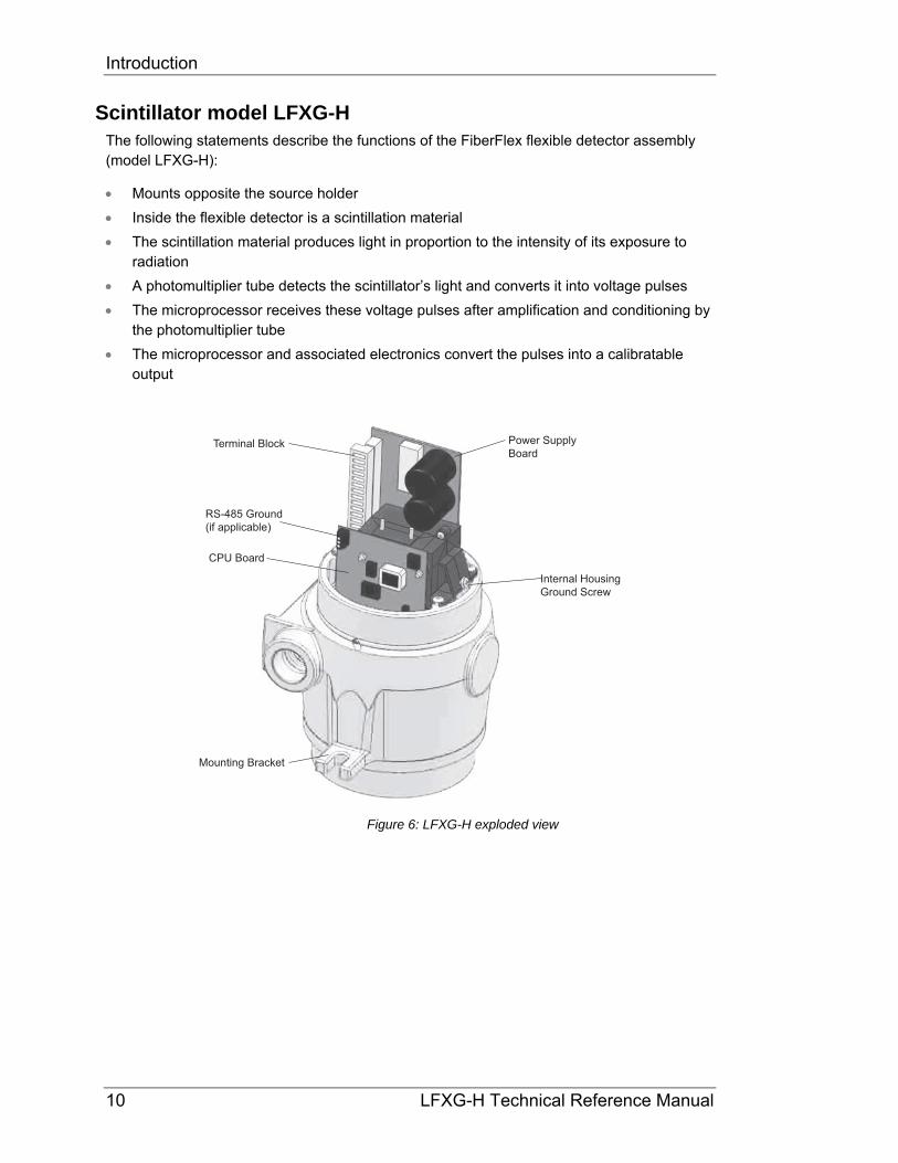
Scintillator model LFXG-H The following statements describe the functions of the FiberFlex flexible detector assembly (model LFXG-H):
Mounts opposite the source holder
Inside the flexible detector is a scintillation material
The scintillation material produces light in proportion to the intensity of its exposure to radiation
A photomultiplier tube detects the scintillator’s light and converts it into voltage pulses
The microprocessor receives these voltage pulses after amplification and conditioning by the photomultiplier tube
The microprocessor and associated electronics convert the pulses into a calibratable output
Terminal Block
RS-485 Ground(if applicable)
CPU Board
Mounting Bracket
Internal HousingGround Screw
Power SupplyBoard
Figure 6: LFXG-H exploded view

Introduction
LFXG-H Technical Reference Manual 11
Communicating with the gauge
The VEGA continuous level gauge is a transmitter, so it produces the current loop signal directly at the measurement site.
Use either a HART Communicator or HART modem and VEGA View or Ohmview 2000 software with a PC to enable the following:
Initial setup
Calibration
Other communication with the gauge
You can make a connection anywhere along the 4 … 20 mA current-loop line. After setup and calibration of the level gauge, there are no day-to-day requirements for external electronics.
Using a universal hand-held terminal VEGA’s LFXG-H level gauge is compatible with the Fisher-Rosemount HART Communicator. The HART (Highway Addressable Remote Transducer) Communicator uses the Bell 202 Frequency Shift Keying technique to superimpose high frequency digital communication signals on the standard 4 … 20 mA current loop. To function, the minimum load resistance on the 4 … 20 mA loop must be 250ohms ().
Refer to the instruction manual for your HART Communicator for information on the following:
Key usage
Data entry
Equipment interface

Introduction
12 LFXG-H Technical Reference Manual
Figure 7: HART hand-held communicator
In order to effectively use the features in VEGA’s level gauge, you must use VEGA’s device description (DD) to program the HART communicator. You may purchase a universal hand-held terminal, programmed with the device, through VEGA (VEGA part number 236907).
Use firmware 2000.00 or higher when you use the hand-held HART communicator to make NORM or vapor compensation. See “Appendix II: Special Applications” for further information concerning NORM and vapor compensation.
Introduction
LFXG-H Technical Reference Manual 13
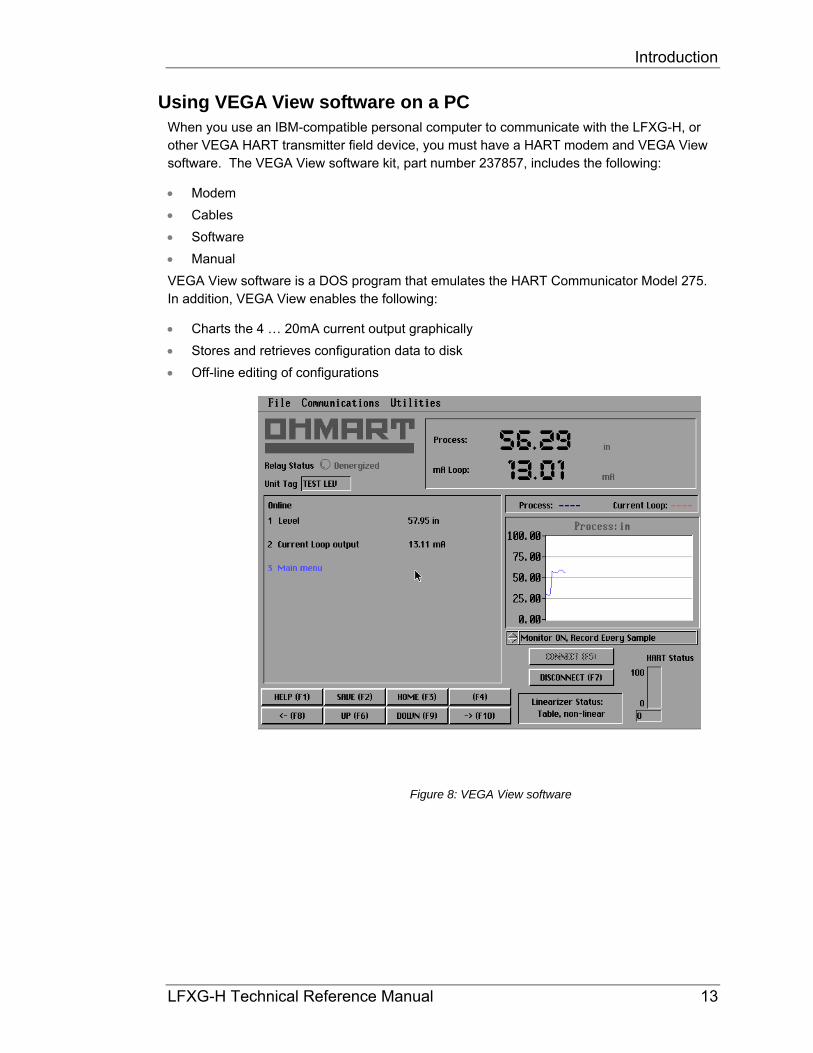
Using VEGA View software on a PC When you use an IBM-compatible personal computer to communicate with the LFXG-H, or other VEGA HART transmitter field device, you must have a HART modem and VEGA View software. The VEGA View software kit, part number 237857, includes the following:
Modem
Cables
Software
Manual
VEGA View software is a DOS program that emulates the HART Communicator Model 275. In addition, VEGA View enables the following:
Charts the 4 … 20mA current output graphically
Stores and retrieves configuration data to disk
Off-line editing of configurations
Figure 8: VEGA View software

Introduction
14 LFXG-H Technical Reference Manual
Note: There are some minor differences in operation of the VEGA View software and the hand-held communicator. Most significantly, VEGA View software writes entries immediately to the level transmitter, but a communicator only sends changes after pressing F2 to send.
This manual’s instructions are for the hand-held communicator, but most procedures use exactly the same steps.
Refer to the VEGA View User Manual that accompanies the software diskette for complete instructions for using VEGA View software.

Introduction
LFXG-H Technical Reference Manual 15
Using Ohmview 2000 Software on a PC When you use an IBM-compatible personal computer with windows and a Pentium processor to communicate with the DSGH, or other VEGA HART transmitter field devices, you must have a HART modem and Ohmview 2000 software. The Ohmview 2000 software kit, part number 243008, includes the following:
Modem
Cables
Software
Ohmview 2000, RS-485 Network, Ohmview 2000 Logger, and Ohmview 2000 Configurator software is a window’s program that emulates the HART Communicator Model 275. In addition, Ohmview 2000 enables the following:
Charts the 4 … 20mA current output graphically
Stores and retrieves configuration data to disk
Off-line editing of configurations
Figure 9: Ohmview 2000 software
Note: There are some minor differences in operation of the Ohmview 2000 software and the hand-held communicator. Most significantly, Ohmview 2000 software writes entries immediately to the transmitter, but a communicator only sends changes after pressing F2 to send.
This manual’s instructions are for the hand-held communicator, but most procedures use exactly the same steps.

Introduction
16 LFXG-H Technical Reference Manual
Refer to the Ohmview 2000 Electronic User Manual that accompanies the software diskette for complete instructions for using Ohmview 2000 software.
The Ohmview 2000 software includes the main Ohmview 2000 software, HART Communication Server, Launcher program, Ohmview 2000 Logger, Ohmview 2000 File Configurator, and the Ohmview 2000 Electronic User Manual. When you insert the disk into your CD drive, the program automatically starts installing these programs onto your hard drive. The HART Communication Server must always be on when using Ohmview 2000’s main program and Ohmview 2000 Logger.
Figure 10: Example of an Ohmview 2000 CD label
Compatible with Windows 95, 98, 2000, NT, and XP
Ohmview 2000 version 1.0.2
Software for Ohmart level and density gauges
Part # 243008

Introduction
LFXG-H Technical Reference Manual 17
The HART screens menu structure
In both the hand-held HART Communicator and the VEGA View or Ohmview 2000 software, the user-interface for HART functions is in a menu structure. When the HART Communicator, or VEGA View, Ohmview 2000 starts up, the Online menu displays.
3 M
ain
men
u1
Lev
el
##
.##
%#
#.#
# m
A
2 C
ur
ou
t
1 In
itia
l set
up
2 C
alib
rati
ons
3 G
auge
sta
tus
4 A
dvan
ced
Fxns
HA
RT
scre
en f
eatu
res
(Tra
nsm
itte
r con
nect
ed)
Figure 11: Online menu
For a detailed list of HART screen sub-menus, see “Appendix IV” of this manual.

Introduction
18 LFXG-H Technical Reference Manual
Notes

LFXG-H Technical Reference Manual 19
Chapter 2: Installation
Testing on the bench
To ensure a quick start up after installation, you can test the detector assembly with the HART compatible communication device (either a universal hand-held terminal or a personal computer with a HART modem and VEGA software). Bench testing enables you to check the following:
Power
Communication
Initial setup software parameters
Some diagnostics
Figure 12: Bench test setup
Note: You may need to reset the time and date if the transmitter has not had power for over 28 days. The Real Time Clock Fail message may display. It is important to enter the correct time and date, because the clock is the basis for source decay calculations. For instructions to set the time and date, see page 106.
Many users choose to calibrate the current loop output “on the bench” before mounting the detector on the process. Refer to page 33 for further information on calibration of the current loop.
PC running Ohmart View
250 to 800ohmload resistor(optional)
HART modem
Mini clips
RS-232 cable
FiberFlexterminals 13&14
H1
H2
Transmittertest points

Installation
20 LFXG-H Technical Reference Manual
Location considerations
At the time you ordered the level transmitter, VEGA sized the source for optimal performance. Notify VEGA prior to installation of the gauge if the location of the gauge is different from the original order location. Proper location of the level gauge can sometimes mean the difference between satisfactory and unsatisfactory operation.
Note: Try to locate the source holder in such a place that process material will not coat it. This ensures the continuing proper operation of the source ON/OFF mechanism. Many regulatory agencies (for example, the U.S. NRC) require periodic testing of the ON/OFF mechanism. Refer to the “Radiation Safety for U.S. General and Specific Licensees, Canadian, and International Users” manual and the “Radiation Safety Manual Addendum of Reference Information” CD that came with the source holder and the appropriate current regulations for details.
Stable temperature Mount the level gauge on a portion of the line where the temperature of the process material is relatively stable. Process temperature can effect the gauge indication. The amount of the effect depends upon the following:
Sensitivity of the gauge
Temperature coefficient of the process material
Protect insulation If insulation is between the measuring assembly and the process, protect the insulation from liquids. The absorption of a liquid, such as water, can affect the gauge indication because it blocks some radiation.
Avoid internal obstructions The best possible installation of a nuclear level gauge is on a vessel that has no internal obstructions (agitator, baffle, manways, and so forth) directly in the path of the radiation beam. If one of these obstructions is present, it can shield the radiation from the detector, causing an erroneous reading. If the vessel has a central agitator, the source holder and detector can mount to the vessel on an arc other than a diameter, so that the beam of radiation does not cross the agitator. You can also avoid other obstructions this way.

Installation
LFXG-H Technical Reference Manual 21
Avoid external obstructions Any material in the path of the radiation can affect the measurement. Some materials that are present when the gauge initially calibrates pose no problem because the calibration accounts for their effect. Examples of these materials are:
Tank walls
Liners
Insulation
However, when the materials change or you introduce new ones, the gauge reading can be erroneous.
Examples of these situations are:
Insulation that you add after calibration absorbs the radiation and causes the gauge to erroneously read upscale.
Rapidly changing tank conditions due to material buildup. Regular standardizations compensate for slowly changing tank conditions due to material buildup. See the “Calibration” chapter for information on standardization.
Avoid source cross-talk When multiple adjacent pipes or vessels have nuclear gauges, you must consider the orientation of the source beams so that each detector senses radiation only from its appropriate source. The best orientation, in this case, is for the source holders to be on the inside with radiation beams pointing away from each other.

Installation
22 LFXG-H Technical Reference Manual
Mounting the measuring assembly
There are two types of mounting options. The first type is the bracket mount. The L bracket supports the electronics housing. For this type of mounting, the conduit clamps should be spaced every 18”.
The second type of mounting is the conduit mount. This type of mount consists of an adapter with a 2” conduit coupler (part number 240721). It provides an air hose fitting for applications that need to cool the detector. The pole mount requires a nipple and union. Figure 13 illustrates the two mounting types.
Note: The detector active area (where it is possible to make a level measurement) is between 1” from the bottom of the detector to the end of the flexible conduit. Mount the detector so that this area spans the desired measurement length.
Note: On most source holders, the handle operates a rotating shutter. When installing or removing the assembly from the pipe, you must turn the handle to the closed or OFF position and lock the handle with the combination lock that VEGA provides.
Figure 13: Conduit and bracket mounting
Conduit mounting
Bracket mounting

Installation
LFXG-H Technical Reference Manual 23
Wiring the equipment
Note: You may have received an interconnect drawing from VEGA or the engineering contractor. If the instructions on the drawing differ from the instructions in this manual, use the drawing. It may contain special instructions specific to your order.
Use the drawing notes and the steps that follow to make the input and output connections. Make the connections at the removable terminal strips mounted on the CPU board. Access the CPU board by removing the explosion-proof housing cap.
VEGA provides an internal and external ground screw for connection of the power Earth ground wire. After removing the top cover, the location of the internal ground screw is at the front of the housing. The location of the external ground screw is next to the conduit entry.
Note: Not all connections are required for operation. See Table 5: Terminal names and descriptions.
Terminal Block
RS-485 Ground(if applicable)
CPU Board
Mounting Bracket
Internal HousingGround Screw
Power SupplyBoard
Figure 14: LFXG-H internal and external ground screw

Installation
24 LFXG-H Technical Reference Manual
Power in [L]
- mA+ mA- Aux+ Aux
Power in [N]Relay NORelay CRelay NC
LFXG-H
Relay
123456789
1011121314
- 6VCOM+ 6V- Freq+ Freq
Figure 15: Interconnect
Table 5: Terminal names and descriptions
Terminal
Name Description
1 L1 AC or DC power input2 L2 AC or DC power input3 RY NO Relay normally open4 RY C Relay common5 RY NC Relay normally closed6 Freq+ Not used in HART applications
7 Freq– Not used in HART applications8 +6 Auxiliary input power9 COM Auxiliary input power common10 –6 Auxiliary input power11 Aux+ Auxiliary input frequency signal 12 Aux– Auxiliary input frequency signal13 mA+ Positive current loop output14 mA– Negative current loop output
Note: The power input terminals are not polarity sensitive.

Installation
LFXG-H Technical Reference Manual 25
Power
CAUTION!
DO NOT APPLY POWER until a thorough check of all the wiring is complete!
The AC power source voltage input is 100–230VAC10% (90–250VAC) at 50/60 Hz, at 15VA (without heater) or 25VA (with optional heater) maximum power consumption. AC power must not be shared with transient producing loads.
The DC power source voltage input is 20–60VDC (less than 100mV, 1/1,000 Hz ripple) at 15VA maximum power consumption. DC power cable can be part of a single cable 4-wire hookup, or can be separate from output signal cable. (See "Output current loop " section)
Use wire between 1.63 to 0.643mm (#14 –#22AWG) for power wiring.
Switch for CE compliance For CE compliance, install a power line switch no more than one meter from the operator control station.
Output current loop Output signal is 4 … 20 mA into 250–800ohms (). HART communication protocol (BEL202 FSK standard) is available on these connections. The output is isolated to standard ISA 50.1 Type 4 Class U.
When using signal (current loop or 4 … 20 mA output) cables that VEGA did not supply, the cables should meet the following specifications:
Maximum cable length is 1,000m (3,280ft)
All wires should be 1.02–0.643mm (#18 or #22AWG)
If using DC power, signal and power can run on a single cable 4-wire hookup (two wires for power, two for 4 … 20 mA).

Installation
26 LFXG-H Technical Reference Manual
Communication The HART hand-held terminal can connect anywhere across the 4 … 20 mA wires to communicate with the level transmitter. A minimum requirement is a 250 load-resistance on the current loop. The hand-held terminal is Rosemount model 275 or equivalent (VEGA number 236907).
A HART modem may also connect across the 4 … 20 mA wires to enable communication between the level transmitter and an IBM compatible PC.
Process alarm override switch If the output relay is set as a process alarm relay (high or low-level alarm), you can install an override switch to manually deactivate the alarm. If you do not install an override switch, the process alarm relay de-energizes only when the measured level is out of the alarm condition. The function of the output relay is set in the Alarms screen from the Initial Setup menu.
Conduit Conduit runs must be continuous and you must provide protection to prevent conduit moisture condensation from dripping into any of the housings or junction boxes. Use sealant in the conduit, or arrange the runs so that they are below the entries to the housings and use weep holes where permitted.
You must use a conduit seal-off in the proximity of the housing when the location is in a hazardous area. Requirements for the actual distance must be in accordance with local code.
If you use only one conduit hub, plug the other conduit hub to prevent the entry of dirt and moisture.

Installation
LFXG-H Technical Reference Manual 27
Commissioning the gauge
The process of commissioning the gauge includes the following:
Taking appropriate radiation field tests
Checking the pre-programmed setup parameters
Calibrating on process
Verifying the working of the gauge.
VEGA Field Service Engineers typically commission the gauge. It is necessary to remove the source holder lock the first time the gauge takes measurements in the field. Only persons with a specific license from the U.S. NRC, Agreement State, or other appropriate nuclear regulatory body may remove the source holder lock.
Note: Users outside the U.S. must comply with the appropriate nuclear regulatory body regulations in matters pertaining to licensing and handling the equipment.
Can you remove the source holder lock? If you are in doubt whether you have permission to remove the source holder lock…Do not!
The license sets limits on what the user can do with the gauge. Licenses fall into two categories:
1. General
2. Specific

Installation
28 LFXG-H Technical Reference Manual
It is up to the user to review the license to determine if they have the appropriate permission to perform any of the following:
Disassemble
Install
Relocate
Repair
Test
Unlock
Note: Low activity source holders have different requirements from a typical source holder. Contact VEGA Americas, Inc. for information regarding low activity source holders..

Installation
LFXG-H Technical Reference Manual 29
You can remove the source lock if installation of the gauge is in the U.S. and you have the specific license to remove the source holder lock. Confirm that your license specifically states that you have the permission to perform this operation and then contact VEGA Field Service Radiation Safety for the combination.
Do not remove the lock if the gauge has a general license tag, installation is in the U.S., and you do not have the specific license that gives you permission to remove the lock. You can verify whether the gauge is a general license gauge by checking the source holder for the general license tag. If it is not there, it is not a general license device.
If you do not have permission to remove the source holder lock, an VEGA Field Service Engineer or another person with this specific license must remove it for you.

Installation
30 LFXG-H Technical Reference Manual
Field service commissioning call checklist In many U.S. installations, an VEGA Field Service Engineer commissions the gauge. To reduce service time and costs, use this checklist to ensure the gauge is ready for commission before the Field Service Engineer arrives:
Mount the source holder and detector per the certified drawings found in the custom information folder in this manual, allowing access for future maintenance
Make all wiring connections per the certified drawings and the “Wiring the Equipment” section in this manual. Tie in the wiring from the field transmitter analog output to the DCS/PLC/chart recorder
Ensure that the AC power to the transmitter is a regulated transient-free power source. UPS type power is the best
If using DC power, verify that the ripple is less than 100mV
Note: The equipment warranty is void if there is damage to the gauge due to incorrect wiring not checked by the VEGA Field Service Engineer.
Have process ready for calibration
When possible, it is best to have process available near both the low and high end of the measurement span
When possible, it is best to be able to completely fill and empty the vessel, at the high and low levels for the initial calibration procedure, and when possible at 10% increments in between for the linearization procedure
Do not remove the lock on the source holder. Notify VEGA Field Service if there is
damage to the lock or it is missing.

LFXG-H Technical Reference Manual 31
Chapter 3: Calibration
All of these functions group together in the Calibrations screens. See “Appendix IV” of this manual for Calibrations menus and screens.
Before using the level transmitter to make measurements, you must perform the following:
Calibrate it to relate the detection of radiation from the source to the level of the process material
Calibrate the current loop to a reference ammeter or the DCS
Periodically, you must standardize the system on process to adjust for changes over time
Calibration establishes a reference point or points that relate the detector output to actual (or known) values of the process.
You must perform a calibration before the gauge can make measurements of any accuracy. Perform the calibration after the installation and commission of the gauge at the actual field site.
You do not need to repeat the calibration procedures as long as certain critical process and equipment conditions remain the same. See “When a New Calibration May Be Necessary” in this manual. The gauge requires only a periodic standardization to compensate for changing conditions.

Calibration
32 LFXG-H Technical Reference Manual
Current loop (analog output) calibration
Calibrating the current loop adjusts the 4 … 20 mA output to a reference—either the PLC/DCS or a certified ammeter. It forces the 4 and 20 mA outputs to the external reference. The VEGA factory pre-adjusts the current loop with a certified ammeter, so it is very close to the outputs required.
To correlate the 4 … 20 mA to the process value, set the span of the current loop output in the Loop Span screen from the Initial setup, Process parameters, Spans, Current Loops Span menu. See the “Appendix I, Initial Factory Setup” section for details.
Note: The current loop and process spans are independent and set separately. The current loop span sets the level indications for the 4 and the 20 mA outputs. The process span sets the endpoints of the calibration curve. The current loop span and process span are set in the Initial setup screen from the Main menu.
A quick way to check the span settings is to use the View settings menu from the Initial setup menu.
A direct measurement of the current is preferable. Take this measurement by hooking the meter up in series with the instrument and the DCS. However, if you know the resistance of the DCS, use a voltage measurement to calculate the current.
Detector housing Terminal blockpins 13 & 14
Current meter
Rt
DCS DCSRt
Volt meter
Terminal blockpins 13 & 14
Detector housing
Figure 16: Measuring the current loop output
Calibration
LFXG-H Technical Reference Manual 33
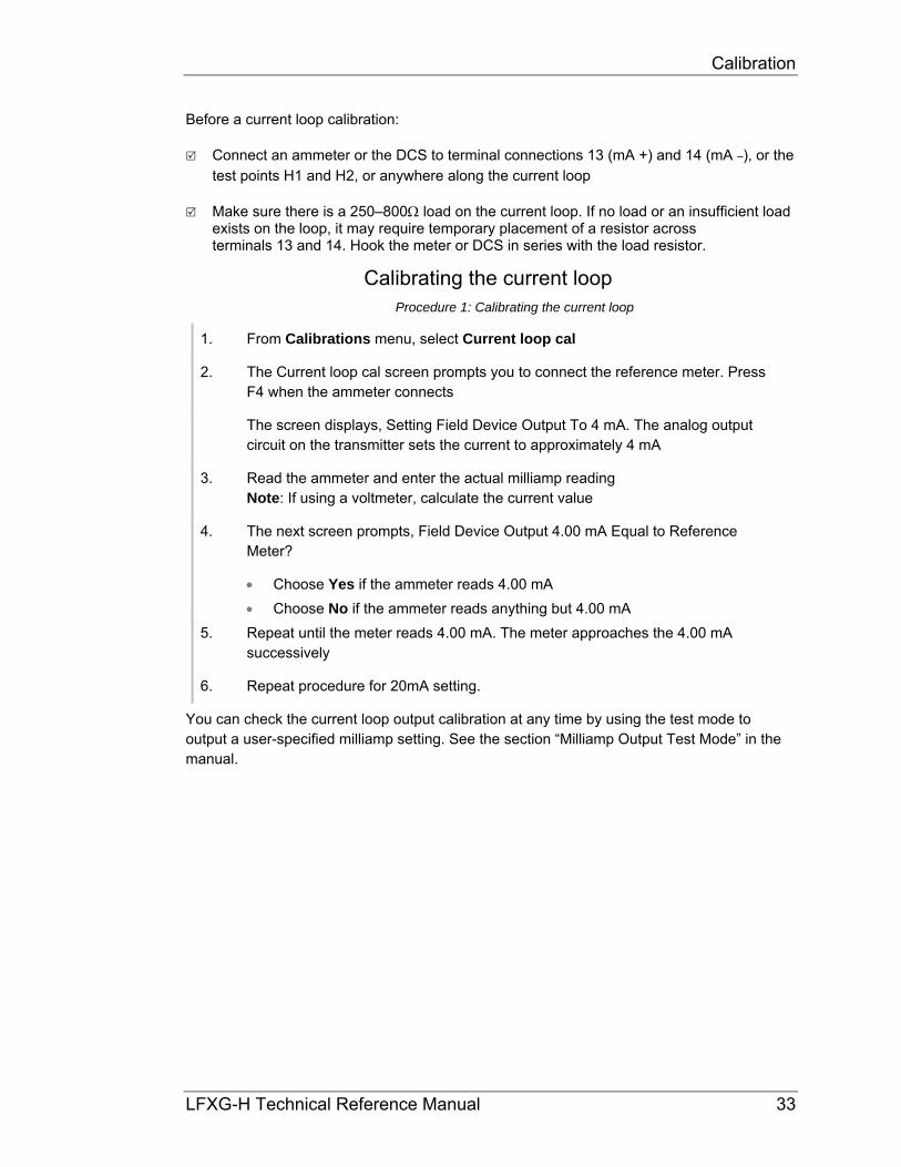
Before a current loop calibration:
Connect an ammeter or the DCS to terminal connections 13 (mA +) and 14 (mA –), or the test points H1 and H2, or anywhere along the current loop
Make sure there is a 250–800 load on the current loop. If no load or an insufficient load exists on the loop, it may require temporary placement of a resistor across terminals 13 and 14. Hook the meter or DCS in series with the load resistor.
Calibrating the current loop Procedure 1: Calibrating the current loop
1. From Calibrations menu, select Current loop cal
2. The Current loop cal screen prompts you to connect the reference meter. Press F4 when the ammeter connects
The screen displays, Setting Field Device Output To 4 mA. The analog output circuit on the transmitter sets the current to approximately 4 mA
3. Read the ammeter and enter the actual milliamp reading Note: If using a voltmeter, calculate the current value
4. The next screen prompts, Field Device Output 4.00 mA Equal to Reference Meter?
Choose Yes if the ammeter reads 4.00 mA
Choose No if the ammeter reads anything but 4.00 mA
5. Repeat until the meter reads 4.00 mA. The meter approaches the 4.00 mA successively
6. Repeat procedure for 20mA setting.
You can check the current loop output calibration at any time by using the test mode to output a user-specified milliamp setting. See the section “Milliamp Output Test Mode” in the manual.

Calibration
34 LFXG-H Technical Reference Manual
Choosing the calibration method
For each installation, the user must choose one of two ways to calibrate the level transmitter. The best calibration method depends on how you use the continuous level transmitter. Read the following table to decide which method to use.
Table 6: Calibration methods
Standard method Simple method
Use the standard method if…the gauge is required to be repeatable and accurately indicate the level of process throughout the span.
Use the simple method if…the gauge is only required to be repeatable, but need not accurately indicate the level of process.
Typically used for vessels in which it is critical to know the accurate level.
Typically used for surge bins or other vessels under control that maintains one level.
The linearizer type chosen must be “Non-linear table” The linearizer type chosen must be “Linear table”
Note: The simple calibration method produces a measurement indication that is repeatable but not accurate between the Cal Low Level and Cal High Level points. The measurement indication is not linear with respect to the actual process level.
In some applications, accuracy is not critical and this method is valid.
If your application requires a linear or accurate indication of the actual process level, you must use the standard method of calibration

Calibration
LFXG-H Technical Reference Manual 35
Standard method of calibration
Figure 17 illustrates the steps to prepare for and perform a standard method calibration.
Are process units setcorrectly?
Is linearizer set to Table,non-linear?
Start
Change units in Initial setupscreens
Change linearizer to Table, non-linearin Calibrations/ Linearizer screen
Collect linearizer data on knownsamples using the function Collect
data point in the Linearizer screens
Perform Calc linearityfunction in the
Linearizer screens
Perform Cal resultfunction in Initial cal
screens
Is process span setcorrectly?
Perform Set Cal low level and SetCal high level steps (in any
sequence) in Initial cal screens.
Change measurement span inInitial setup screens
Yes
Yes
Yes
No
No
No
Perform these datacollection steps in any
sequence
Figure 17: Standard method calibration flow chart

Calibration
36 LFXG-H Technical Reference Manual
Table 7: Standard method calibration
Standard method calibration
Step in flow chart Manual heading Page
Check process engineering units Units 98
Check process span Span settings, process span 103
Check linearizer type, set to table, non-linear Choosing the linearizer type 38
Check the repeatability of measurement Checking the gauge repeatability 43
Perform “Set Cal low level” and “Set Cal high level”
Step 1: Set low level Step 2: Set high level
46 47
Collect linearizer data on known samples Step 3: Collecting linearizer table data 47
Perform “Calc linearity” Step 4: Calculating the linearity 49
Perform “Cal result” Step 5: Calculate calibration 49

Calibration
LFXG-H Technical Reference Manual 37
Simple method of calibration
Figure 18 illustrates the steps to prepare for and perform a simple method calibration.
Are process units setcorrectly?
Is linearizer set to Table,linear?
Start
Change units in Initial setupscreens
Change linearizer to Table, linear inCalibrations/ Linearizer screen
Perform Cal resultfunction in Initial cal
screens
Is process span setcorrectly?
Perform Set Cal low level and SetCal high level steps (in any
sequence) in Initial cal screens.
Change measurement span inInitial setup screens
Yes
Yes
Yes
No
No
No
Figure 18: Simple method calibration flow chart
Calibration
38 LFXG-H Technical Reference Manual
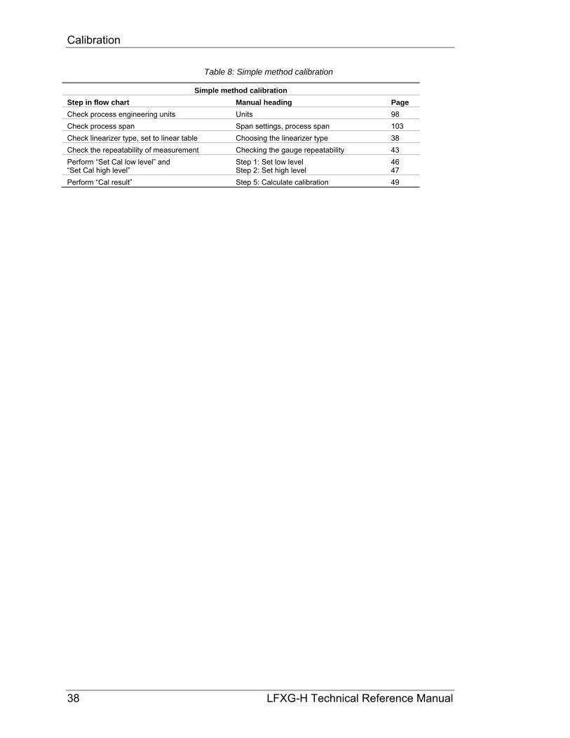
Table 8: Simple method calibration
Simple method calibration
Step in flow chart Manual heading Page
Check process engineering units Units 98
Check process span Span settings, process span 103
Check linearizer type, set to linear table Choosing the linearizer type 38
Check the repeatability of measurement Checking the gauge repeatability 43
Perform “Set Cal low level” and “Set Cal high level”
Step 1: Set low level Step 2: Set high level
46 47
Perform “Cal result” Step 5: Calculate calibration 49

Calibration
LFXG-H Technical Reference Manual 39
Theory of calibration
This section explains both the standard and simple methods of calibration.
Both calibration methods Enter the values that define the maximum and minimum levels to measure in the Process span screens, from the Initial setup, Process parameters, Spans menus. These parameters are Max Level and Min Level, and must be set correctly before any of the calibration steps.
Both calibration methods Collection of data points nearest the Maximum (but not higher) and Minimum (but not lower) levels occurs during calibration. Refer to the “Two Point Cal“ procedure in this manual for the steps necessary to collect these data points. In Figure 19, stars indicate the Maximum and minimum level data points.
Standard calibration method A standard calibration method requires collection of intermediate data points. Use the Linear data collect function from the Calibrations, Linearizer menus to collect these data points. In Figure 19, circles indicate the intermediate data points.
CalLowLevel
CalHighLevel
RawSensorCounts
Actual Level (eng units)
Cal LowCounts
Cal HighCounts
MaxLevel
MinLevel
Figure 19: Linearizer data collected at various process levels

Calibration
40 LFXG-H Technical Reference Manual
Simple calibration method The simple method of calibration does not require collection of intermediate data points.
Standard calibration method Internal software calculates a linearizer curve based on data points. The curve is the most accurate between the Cal Low Level and Cal High Level, as shown in Figure 20. For this reason, it is best to take the Cal Low and Cal High samples as close as possible to the Min Level and Max Level to maximize the accuracy within the span.
Simple calibration method Based on the Cal Low Level and Cal High Level, the internal software calculates a straight line between the Min Level and Max Level.
CalLowLevel
CalHighLevel
RawSensorCounts
Actual Level (eng units)
Cal LowCounts
Cal HighCounts
MaxLevel
MinLevel
Standard
Simple
Figure 20: Raw counts vs. actual level with linearizers
Standard calibration method The linearizer curve maps on two axes so that it indicates % Count Range vs. % Span, as shown in Figure 21. To construct the linearizer table, a data point calculates for every 2.5% of the span. View or edit these points in the Linearizer table screen.
Simple calibration method The internal software calculates a straight line between the Min Level and Max Level based on the Cal Low Level and Cal High Level.

Calibration
LFXG-H Technical Reference Manual 41
%CountRange
% Span100%
0%
0%
100%
Standard
Simple
Figure 21: %Count range vs. %span (shown in linearizer table)
Both calibration methods Figure 22 illustrates the effect on the final output of using the non-linear table vs. the linear table for the linearizer. Using the non-linear table linearizer in the standard method produces a linear output. Using the linear table linearizer table produces a non-linear output.
IndicatedLevel
ActualLevel
Max Level
Min Level
Min Level
Max Level
Standard
Simple
Figure 22: Indicated level vs. actual level
Calibration
42 LFXG-H Technical Reference Manual
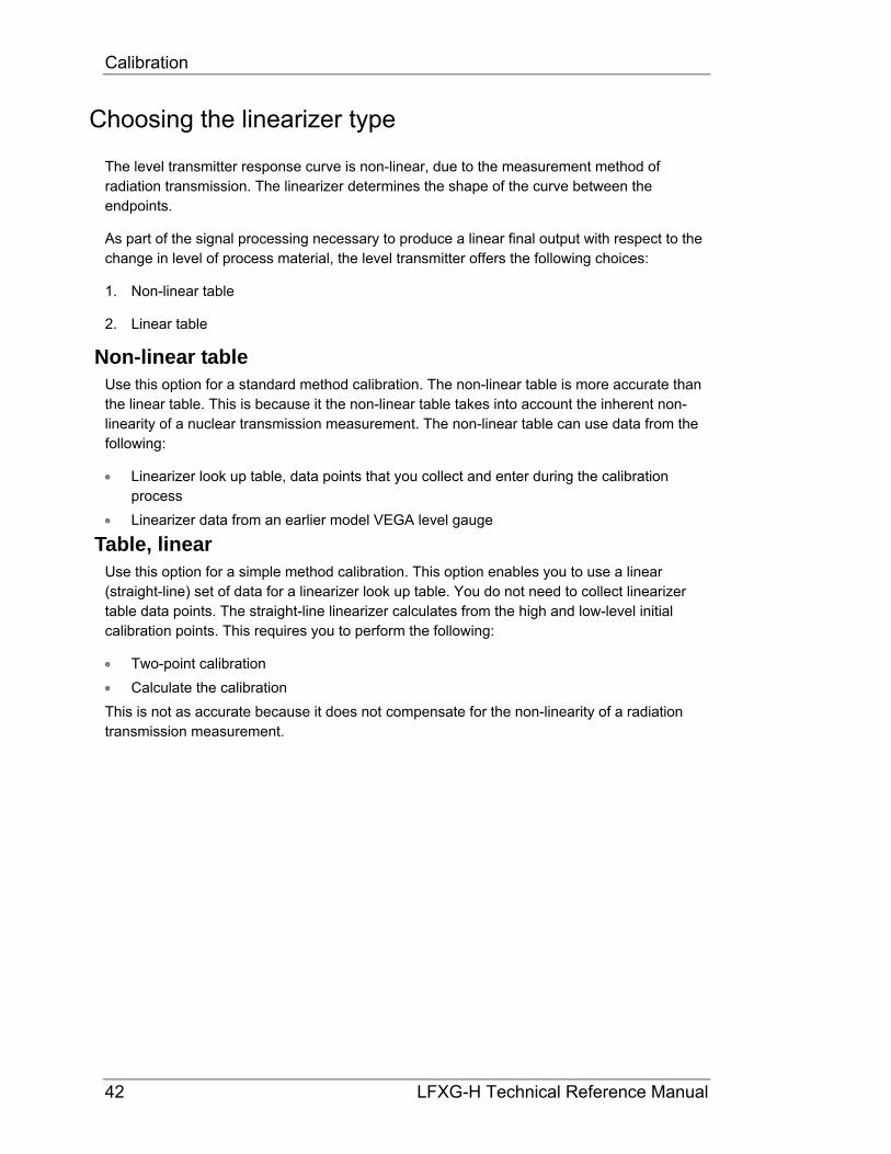
Choosing the linearizer type
The level transmitter response curve is non-linear, due to the measurement method of radiation transmission. The linearizer determines the shape of the curve between the endpoints.
As part of the signal processing necessary to produce a linear final output with respect to the change in level of process material, the level transmitter offers the following choices:
1. Non-linear table
2. Linear table
Non-linear table Use this option for a standard method calibration. The non-linear table is more accurate than the linear table. This is because it the non-linear table takes into account the inherent non-linearity of a nuclear transmission measurement. The non-linear table can use data from the following:
Linearizer look up table, data points that you collect and enter during the calibration process
Linearizer data from an earlier model VEGA level gauge
Table, linear Use this option for a simple method calibration. This option enables you to use a linear (straight-line) set of data for a linearizer look up table. You do not need to collect linearizer table data points. The straight-line linearizer calculates from the high and low-level initial calibration points. This requires you to perform the following:
Two-point calibration
Calculate the calibration
This is not as accurate because it does not compensate for the non-linearity of a radiation transmission measurement.

Calibration
LFXG-H Technical Reference Manual 43
Choosing a linearizer method Procedure 2: Choosing a linearizer method
1. From the Online menu, select Main menu
2. From the Main menu, select Calibrations
3. From the Calibrations menu, select Linearizer
4. From the Linearizer menu, choose Select linearizer
5. On the Select linearizer screen, the currently used linearizer is displayed on the second line
6. From the Select linearizer screen, select either:
Table, non-linear
Table, linear
7. Press F4 to enter.
Refer to “Appendix III” for further instructions if you choose the Table, linear option.
Checking the gauge repeatability
Check the level transmitter measurement repeatability before performing the calibration.
Access the Data collect function in the Data Collect screen, from the Calibrations menu to enable simple measurement of the process, without altering the calibration or standardization values. It enables the system to measure the process and report the number of sensor counts. For more information about counts and the calculations performed to produce the final process value, see the “Process Chain” section in the “Advanced Functions” chapter.
You can perform a data collect three or four times on the same level to check the repeatability of the sensor. If the sensor counts vary widely, you should increase the Data collection interval parameter from the Initial setup menu, Process parameters menu, Data coll interval screen. Refer to page 99 for further information.

Calibration
44 LFXG-H Technical Reference Manual
Performing a data collect Procedure 3: Performing a data collect
1. From the Main menu, select Calibrations
2. From the Calibrations menu, select Data collect
3. At the prompt, select Yes to enable the data collection to take place. The on-screen counter displays the time left. Press F3 to abort if necessary to discontinue data collect
4. After data collection, the screen displays the number of counts (cnts) output by the sensor. Make note of the counts value
5. Repeat as often as necessary if checking repeatability.
Calibrating the gauge
The standard calibration method involves five main steps:
1. Setting the low level and collecting Cal low data*
2. Setting the high level and collecting Cal high data*
3. Collecting linearizer data*
4. Calculating the linearizer
5. Calculating the calibration
* Perform these data collection steps in any sequence. Your ability to empty and fill the vessel determines the best
sequence.
The simple calibration method skips Step 3 and 4.
If using the standard calibration method, you may find it helpful to record the sensor counts and levels at each step on Table 9.

Calibration
LFXG-H Technical Reference Manual 45
Table 9: Standard calibration sensor counts and levels record
Data type Sensor counts Actual level (eng units)
Cal low level (usually empty) Linearizer data point 0
Linearizer data point 1
Linearizer data point 2
Linearizer data point 3
Linearizer data point 4
Linearizer data point 5
Linearizer data point 6
Linearizer data point 7
Linearizer data point 8
Linearizer data point 9
Cal high level (usually full)
and
Linearizer data point 10

Calibration
46 LFXG-H Technical Reference Manual
Step 1: Set low level Setting the low level for calibration requires the following activities
Measurement with the level transmitter of the low process level
Entry of the actual level
This sets the low end (sometimes referred to in the U.S. as “zero”) of the calibration curve. Perform this procedure either before or after setting the high level.
Note: You must perform data collection for the low and high level within ten days of each other for a good calibration. The low and high values must be more than 10 percent of the process span apart for the most accurate calibration.
Increasing the process span usually increases the gauge accuracy.
Before starting the cal low data collection:
Fill vessel to its low level
Have actual level value ready to enter
Setting the cal low level Procedure 4: Setting the cal low level
1. From the Main menu, select Calibrations
2. From the Calibrations menu, select Initial cal
3. From the Initial cal menu, select Two point cal
4. From the Two point cal menu, select Set Cal low level
5. The prompt, Set process to desired value. Take data? displays. Select Yes to enable the data collection to take place. The on-screen counter displays the time left. If necessary, press F3 to discontinue data collection
6. After collection of the data, the screen prompts you to input the actual value. Input the actual value in engineering units
7. If using a hand-held Communicator, press F2 to send the calibration setting to the level gauge.

Calibration
LFXG-H Technical Reference Manual 47
Step 2: Set high level Setting the high level for calibration requires the following activities:
Measurement with the level transmitter of the high process condition
Entry of the actual level
This sets the “gain” of the calibration curve. Perform this procedure either before or after setting the low level.
Note: You must perform data collection for the low and high level within ten days of each other for a good calibration. The low and high values must be more than 10 percent of the process span apart for the most accurate calibration.
Increasing the process span usually increases the gauge accuracy.
Before starting the cal high data collection:
Fill vessel or pipe with high process, or close the source holder shutter to simulate high process
Have actual level ready to enter
Setting the cal high level Procedure 5: Setting the cal high level
1. From the Main menu, select Calibrations
2. From the Calibrations menu, select Initial cal
3. From the Initial cal menu, select Two point cal
4. From the Two point cal menu, select Set Cal high level
5. The prompt, Set Process To High Calibration Point. Take Data? displays. Select Yes to allow the data collection to take place. The on-screen counter displays the time left. If necessary, press F3 to discontinue data collection
6. After data collection, the screen prompts you to input the actual value in engineering units. The prompt, Input Actual Value, displays. Enter the actual level in engineering units
7. If using a hand-held communicator, press F2 to send the calibration setting to the level transmitter.
Calibration
48 LFXG-H Technical Reference Manual
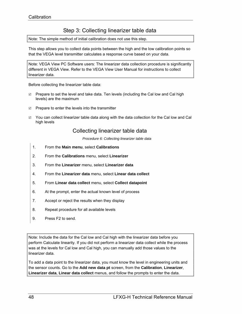
Step 3: Collecting linearizer table data
Note: The simple method of initial calibration does not use this step.
This step allows you to collect data points between the high and the low calibration points so that the VEGA level transmitter calculates a response curve based on your data.
Note: VEGA View PC Software users: The linearizer data collection procedure is significantly different in VEGA View. Refer to the VEGA View User Manual for instructions to collect linearizer data.
Before collecting the linearizer table data:
Prepare to set the level and take data. Ten levels (including the Cal low and Cal high levels) are the maximum
Prepare to enter the levels into the transmitter
You can collect linearizer table data along with the data collection for the Cal low and Cal high levels
Collecting linearizer table data Procedure 6: Collecting linearizer table data
1. From the Main menu, select Calibrations
2. From the Calibrations menu, select Linearizer
3. From the Linearizer menu, select Linearizer data
4. From the Linearizer data menu, select Linear data collect
5. From Linear data collect menu, select Collect datapoint
6. At the prompt, enter the actual known level of process
7. Accept or reject the results when they display
8. Repeat procedure for all available levels
9. Press F2 to send.
Note: Include the data for the Cal low and Cal high with the linearizer data before you perform Calculate linearity. If you did not perform a linearizer data collect while the process was at the levels for Cal low and Cal high, you can manually add those values to the linearizer data.
To add a data point to the linearizer data, you must know the level in engineering units and the sensor counts. Go to the Add new data pt screen, from the Calibration, Linearizer, Linearizer data, Linear data collect menus, and follow the prompts to enter the data.

Calibration
LFXG-H Technical Reference Manual 49
Step 4: Calculating the linearity
Note: The simple method of initial calibration does not use this step.
After collecting the data for a linearizer table, the transmitter uses the data to calculate a new calibration linearizer table. The Calc linearity function initiates this calculation. You must perform this step before the Calculate Calibration step, described in the next section.
Calculating a new linearizer table Calculate the linearizer after you perform the following steps:
Select non-linear table for the linearizer curve
Collect linearizer data
Procedure 7: Calculating the linearizer
1. From the Main menu, select Calibrations
2. From the Calibrations menu, select Linearizer
3. From the Linearizer menu, select Linearizer data
4. From the Linearizer data menu, select Linear data collect
5. From the Linear data collect menu, select Calc linearity
6. At the prompt, select Yes to proceed with the linearity calculation. The linearizer table calculates based on the level values
7. Press F2 to save.

Calibration
50 LFXG-H Technical Reference Manual
Step 5: Calculate calibration After collecting the high and low level calibration data and calculating the linearity, the level transmitter is ready to make the calibration calculation.
Calculating the calibration result Procedure 8: Calculating the calibration result
1. From the Main menu, select Calibrations
2. From the Calibrations menu, select Initial cal
3. From the Initial cal menu, select Two point cal
4. From the Two point cal menu, select Cal result
5. The screens display the results of the cal low and cal high sensor counts and values. Review the values. You can manually edit the counts and actual or new data can be collected by repeating the Set low and Set high procedures, or press F4 to continue
6. The prompt, Proceed with Calibration Calculation?, displays. Select Yes to proceed with the calculation
7. Press F2 to save.

Calibration
LFXG-H Technical Reference Manual 51
When a new calibration may be necessary
Under most circumstances, you do not need to repeat the calibration procedure. The system requires only periodic standardization to compensate for drifts over time. However, certain events necessitate a new initial calibration. The events are:
Measurement of a new process application (contact VEGA for recommendation)
Process requires a new measurement span
Entry of a new measurement span setting into the software
Installation of a new radiation source holder
Moving the level transmitter to another location (in U.S. only specifically licensed persons may relocate the gauge)
Changes to the process vessel, for example: lining, insulation, or agitator
Excessive build up or erosion of vessel that standardization cannot compensate for (check standardize gain)
Standardize gain is greater than 1.2 after a standardization, indicating it made a 20% adjustment from the initial calibration
Periodic process standardization Standardization adjusts the system by resetting one point of the calibration curve to an independently measured or known level.
The frequency of standardization depends on several factors, including desired accuracy of the reading.
During the standardization procedure, the system displays either:
A default value for the standardization condition
A prompt to enter the actual level of the standardization condition
The Initial factory setup appendix details how to set up the software for either prompt.
Automatic standardization reminder If you enable the standardization due alarm, the level transmitter alarms when standardization is due. The standardize interval is programmed into the calibration parameters setup. Refer to “Appendix I, Initial Factory Setup”, for details on the following subjects:
Output relay setup
Standardization due alarm
Standardization interval

Calibration
52 LFXG-H Technical Reference Manual
Performing a standardization Standardizing the gauge Procedure 9: Standardizing the gauge
1. From the Main menu, select Calibrations
2. From the Calibrations menu, select Process stdz
3. The Process stdz screen prompts if you want to take data. Select Yes if you are ready with the standardization material in the process vessel to continue the standardization procedure. The timer counts down while it is collecting data
4. Depending on how the system is set up, it displays one of the following:
The message, Gage Set up to Use Default Value, indicates the system is using the default value as the actual value of the standardization material
A screen that displays the detector counts, the calculated process value, and a field for the user to input the actual value of the level. The prompt asks, Edit Counts? Select No to continue or Yes to input the average counts
5. Press F2 to send.

LFXG-H Technical Reference Manual 53
Chapter 4: Advanced functions
Functions not required for normal operation of the transmitter are found in the software menu structure under the heading, Advanced Fxns. These functions are primarily for use by VEGA personnel for advanced troubleshooting and repair. This chapter gives a basic explanation of these functions.
Note: VEGA strongly recommends that you ask our advice before using any of these advanced functions.
Process chain
The process chain is a description of the transmitter software’s calculation of a level measurement from a radiation reading. In the Process chain screen, you can view intermediate values of the calculation to verify proper functionality of the software.
Primary channel Press the hot spot key () on the hand-held communicator to display the Primary channel screen. The display values for the Primary channel screen are:
Temp Temperature displays the internal probe’s measurement of the sensor temperature.
Sensor cnts Displays the sensor counts that are true counts output, from the sensor, before application of the following:
Temperature compensation
Standardize
Sensor uniformity gains
TC counts Displays temperature compensated counts that are sensor counts with application of temperature compensation.
Raw counts Displays raw counts that are temperature compensated counts with application of uniformity gain.

Advanced functions
54 LFXG-H Technical Reference Manual
Adj counts Displays adjusted or sum counts that are raw counts plus auxiliary raw counts. In most applications, this does not use auxiliary input, so sum counts are equal to raw counts.
SD counts Displays source decay counts that are sum counts with application of source decay gain.
Stdz counts Displays standardize counts that are source decay counts with application of standardization gain.
% Cnt range Displays compensated measurement counts that express as a percent of the counts at the high and low-endpoints of the calibration (determined with the two point initial calibration.) This quantity shows where the current measurement is in relation to the total count range.
% count range = 100 x (CL – CS) / (CL – CH )
where
CS = sum counts CL,CH = counts at Cal low level and Cal high level CL–CH = counts range
% of span The percent process span indicates the measurement value as a percent of the measurement span. The maximum and minimum level values are input in the Initial setup screens. A graph of percent count range vs. percent process span indicates the non-linearity of the radiation transmission measurement. If using a table linearizer, the values in the table are percent count range and percent process span.
Figure 23: % counts range vs. % process span
% process span
% c
ount
s ra
nge
50%
30%

Advanced functions
LFXG-H Technical Reference Manual 55
Raw level Raw level displays the level in inches without the time constant or rectangular window filter.
Uncomp Lvl Uncompensated level displays the level in inches without the time constant or rectangular window filter.
Level Level displays the process value that is the level or other indication in engineering units, after applying the filter. This value relates to the current loop output.
Process variables The display values for the Process variables screen are:
Counts low Displays the counts-low that is the temperature and sensor uniformity gain compensated counts from the sensor at the Cal low level. Determination of the Cal low level occurs during the initial calibration procedure.
Counts high Displays the counts-high that is the temperature and sensor uniformity gain compensated counts from the sensor at the Cal high level. Determination of the Cal high level occurs during the initial calibration procedure.
Max level Displays the maximum level that is the value, in process units, as entered in the Initial setup screens. Use this to calculate the measurement span.
Min level Displays the minimum level that is the value, in process units, as entered in Initial setup screens. Use this to calculate the measurement span.
Temp comp gain Temperature compensation gain displays the current value of the temperature compensation gain. Use this to adjust for inherent sensor output change with temperature.
Uniformity gain Uniformity gain displays the current of the uniformity gain. Use this to force all level sensors to output the same counts at a given radiation field. Most level applications do not use uniformity gain and have it set as default value of 1.0.
Source decay gain Source decay gain displays the current value of the source decay gain. Use this to compensate for the natural decay of the radiation source, which produces a lower field over time.
Stdz gain

Advanced functions
56 LFXG-H Technical Reference Manual
Displays the current value of the standardize gain that adjusts with each standardize procedure.
HV setting HV setting displays the HV setting feature that is the set point for sensor high voltage.
Aux channel chain The display values for the Aux channel chain screen are:
Aux raw counts The Auxiliary raw counts field displays the frequency-input counts from optional auxiliary input.
Filt counts Filtered counts displays the filtered auxiliary counts. The filter dampening value is the number to enter for the auxiliary input filter time constant.
Min/Max history
The min/max history displays the minimum and maximum value for parameters since the last min/max reset. The display values are:
Temp min/max Temperature minimum and maximum displays the internal temperature of the scintillator sensor in the LFXG-H model level transmitter.
Sensor min/max The sensor minimum and maximum field displays raw uncompensated counts from the detector.
Aux in min/max Auxiliary minimum and maximum displays auxiliary input (if used) counts.
Last reset Displays the date of the last min/max reset.

Advanced functions
LFXG-H Technical Reference Manual 57
Resetting the minimum and maximum history You can reset the minimum and maximum history values so that they record from the time of the reset.
To reset the minimum and maximum history Procedure 10: Resetting the minimum and maximum history
1. From the Main menu, select Advanced Fxns
2. From the Advanced Fxns menu, select Min/max history
3. From the Min/max history screen, select Reset min/max
4. When prompted, select Yes to reset the min/max values. Or select No to cancel
5. Press F2 to save.

Advanced functions
58 LFXG-H Technical Reference Manual
New hardware or EEPROM corrupt
The transmitter contains two electrically erasable programmable read only memory (EEPROM) chips. The EEPROMs store all data specific to that sensor/electronics pair for the installation. The locations of the EEPROMs are:
On the CPU board
On the sensor board
Each EEPROM contains a backup of the other EEPROM. The system monitors both EEPROMs at power-up to assure an accurate backup.
If you install a new CPU board, the EEPROM backups on the CPU and sensor boards do not match. The software signals the discrepancy with the error message, New Hardware Found. The transmitter does not automatically perform a backup in case the discrepancy is not due to new hardware, but some corruption of the EEPROM.
Note: Only use the New hardware functions if you replace the CPU board.
This function is not necessary if installing a completely new detector assembly. The new detector assembly includes the CPU board and the sensor assembly.

Advanced functions
LFXG-H Technical Reference Manual 59
Proper response to "New hardware found" message if new hardware has been installed
When you install a new CPU board, you must verify installation in the New hardware screen. This function enables new backups of the EEPROMs.
If a new CPU board has been installed Procedure 11: New Hardware Found message with new CPU board
1. From the Main menu, select Advanced Fxns
2. From the Advanced Fxns menu, select New hardware
3. From the New hardware menu, select New CPU board
4. The prompt, Verify New CPU Board Installed displays. Select Yes to allow new backups on the EEPROMs or select No to cancel.
Proper response to "New hardware found" message if new hardware has not been installed
CPU EEPROM Corrupt message or Sensor EEPROM Corrupt message
If there has not been an installation of a new CPU board and the error message, New Hardware Found, displays, then one of the EEPROMs is probably corrupt. You normally can repair the corruption with the EEPROM backup.
CAUTION!
If you suspect that an EEPROM is corrupt, we recommend you call VEGA Field Service for advice before performing the following procedure.
Advanced functions
60 LFXG-H Technical Reference Manual
To repair the corruption from the EEPROM backup Procedure 12: Repairing corrupted EEPROM
1. From the Main menu, select Advanced Fxns
2. From the Advanced Fxns menu, select New hardware
3. From the New hardware menu, select No new hardware
4. At the prompt, Do You Want To Reconcile Differences?, select Yes to allow restoration from backups on the EEPROMs. Or select No to cancel.

Advanced functions
LFXG-H Technical Reference Manual 61
Test modes
Five independent test modes are available. These test modes are:
1. mA Out test mode
2. Sensor test mode
3. Aux Inp test mode
4. Relay test mode
5. Temperature test
In the test modes, the transmitter stops measuring the process material and allows manual adjustment of critical variables for troubleshooting. The test modes enable independently. However, you can use them in combination to test multiple variable effects. All of the test modes time out automatically after one hour if you do not manually exit.
CAUTION!
While in a test mode, the transmitter is not measuring process and so its current output does not reflect the process value. If your DCS is controlling from the transmitter’s current output, be sure to remove the system from automatic control before entering a test mode. The software screens prompt you to do so before entering test mode.
Milliamp output test mode Use the milliamp output test mode to manually force the current output to a specified value. This is useful for verifying the current loop calibration. Instructions to calibrate the current loop are available in the “Calibration” chapter of this manual.
Note: While in milliamp test mode, the HART communication may post a Status error. This is expected and not an indication of a failure. If the message, Status Error—Ignore Next xx Occurrences? displays, select Yes to ignore the Status Error.

Advanced functions
62 LFXG-H Technical Reference Manual
Start milliamp output test mode Procedure 13: Start mA output test mode
1. From the Main menu, select Advanced Fxns
2. From the Advanced Fxns menu, select Test mode
3. From the Test mode menu, select mA Out test mode
4. From the mA Out test mode menu, select Enter mA test mode
5. At the prompt, enter the value of the current output you want to force
6. At the prompt, select Yes to start the test mode and send new data
7. The transmitter continues functioning in milliamp test mode until it times out after one hour, or until you choose Exit mA test mode.
Exit milliamp output test mode Procedure 14: Exit mA output test mode
1. From the Main menu, select Advanced Fxns
2. From the Advanced Fxns menu, select Test mode
3. From the Test mode menu, select mA Out test mode
4. From the mA Out test mode menu, select Exit mA test mode
5. At the prompt, select Yes to exit the test mode.

Advanced functions
LFXG-H Technical Reference Manual 63
Sensor test mode The sensor test mode simulates the sensor output at a user-defined number of raw counts. This is before application of the following:
Temperature compensation
Sensor uniformity gain
Standardize gain
The true sensor output is ignored while the transmitter is in sensor test mode.
Sensor test mode is extremely useful for verifying the electronics’ and software response to input counts without having to perform the following:
Change the process
Shield the source
Vary the radiation field
While in sensor test mode, after entering the desired number of counts, it may be useful to look at the Process chain screen to view the variables affected by the raw counts value. To view the Process chain screen, back out of the test mode screens pressing the LEFT ARROW. The transmitter continues to operate in sensor test mode until it times out after one hour or until you choose Exit test mode.

Advanced functions
64 LFXG-H Technical Reference Manual
Start sensor test mode Procedure 15: Start Sensor test mode
1. From the Main menu, select Advanced Fxns
2. From the Advanced Fxns menu, select Test mode
3. From the Test Mode menu, select Sensor test mode
4. From the Sensor test mode menu, select Enter test mode
5. At the prompt, enter the value of the new counts you want to force
6. At the prompt, select Yes to start the test mode and send new data
7. The transmitter continues functioning in sensor test mode until it times out after one hour, or until you choose Exit test mode.
Exit sensor test mode Procedure 16: Exit Sensor test mode
1. From the Advanced Fxns menu, select Test mode
2. From the Test mode menu, select Sensor test mode
3. From the Sensor test mode menu, select Exit test mode
4. At the prompt, select Yes to exit the test mode.

Advanced functions
LFXG-H Technical Reference Manual 65
Auxiliary input test mode The auxiliary input test mode simulates the auxiliary input frequency at a user-defined number of counts. The effect of auxiliary input counts depends on the auxiliary input mode. Examples are:
Temperature probe
Flow meter
Second transmitter
While in auxiliary input test mode, after you enter the desired number of counts, it may be useful to look at the Process chain screen to view the variables affected by the auxiliary input counts value. To view the Process chain screen, back out of the test mode screens using the LEFT ARROW. The transmitter continues to operate in auxiliary input test mode until it times out after one hour or until you choose Exit auxiliary input test mode.
Start auxiliary input test mode Procedure 17: Start Auxiliary test mode
1. From the Main menu, select Advanced Fxns
2. From the Advanced Fxns menu, select Test mode
3. From the Test Mode menu, select Aux Inp test mode
4. From the Aux Inp test mode menu, select Aux Inp test mode
5. At the prompt, select Yes to adjust counts
6. Input the Aux counts that you want to force
7. At the prompt, select Yes to start test mode and send new data
The transmitter continues functioning in auxiliary test mode until it times out after one hour, or until you choose Exit Aux test mode.
Exit auxiliary input test mode Procedure 18: Exit Auxiliary test mode
1. From the Advanced Fxns menu, select Test mode
2. From the Test mode menu, select Aux Inp test mode
3. From the Aux Inp test mode menu, select Exit Aux test mode
4. At the prompt, select Yes to exit the test mode.

Advanced functions
66 LFXG-H Technical Reference Manual
Relay test mode Relay test mode enables the user to manually toggle the relay on or off to test the contacts. This is useful for verifying the functioning of alarm annunciators.
Start relay test mode Procedure 19: Start Relay test mode
1. From the Main menu, select Advanced Fxns
2. From the Advanced Fxns menu, select Test mode
3. From the Test Mode menu, select Relay test mode
4. From the Relay test mode menu, select Enter mA test mode
5. At the prompt, select Energize relay or De-energize relay
The transmitter continues functioning in Relay test mode until it times out after one hour, or until you choose Exit relay test.
Exit relay test mode Procedure 20: Exit Relay test mode
1. From the Advanced Fxns menu, select Test mode
2. From the Test mode menu, select Relay test mode
3. From the Relay test mode menu, select Exit relay test.

Advanced functions
LFXG-H Technical Reference Manual 67
Temperature test mode The temperature test mode enables the user to manually force the LFXG-H sensor temperature probe output to a specified value. This is useful for verifying the scintillator sensor temperature compensation. Start temperature test mode
Procedure 21: Start Temperature test mode
1. From the Main menu, select Advanced Fxns
2. From the Advanced Fxns menu, select Test mode
3. From the Test mode menu, select Temperature test mode
4. From the Temperature test mode menu, select Enter Temp. test
5. At the prompt, enter the value of the new temperature you wish to force
The transmitter continues functioning in Temperature test mode until it times out after one hour, or until you choose Exit Temp. test mode.
Exit temperature test mode Procedure 22: Exit Temperature test mode
1. From the Advanced Fxns menu, select Test mode
2. From the Test mode menu, select Temp. test mode
3. From the Temp. test mode menu, select Exit Temp. test mode
4. At the prompt, select Yes to exit the test mode.

Advanced functions
68 LFXG-H Technical Reference Manual
Other advanced functions
Checking the sensor voltage, poll address, equipment version, serial numbers, and temperature coefficients
When performing diagnostics, it may be important to know the following information:
Sensor voltage
Poll address
Version of firmware on the FLASH installed on the level transmitter
Hardware version number
Equipment serial numbers
Temperature coefficients
Sensor voltage Sensor voltage displays the scintillator sensor voltage
Poll address Poll address displays the HART poll address of the transmitter. Each transmitter in a current loop must have a unique poll address. This value is meaningful only when multiple transmitters connect on the same loop.
Firmware version Firmware version displays the firmware version number.
Hardware version Hardware version displays the hardware version number.
CPU Serial Number CPU Serial Number displays the CPU serial number.
Sensor Serial Number Sensor Serial Number displays the sensor serial number.
View temperature coefficients The algorithm that compensates for variations in measurement output with changes in temperature uses temperature coefficients. The VEGA factory determines the coefficients through rigorous testing. You cannot change these values through normal operation.

Advanced functions
LFXG-H Technical Reference Manual 69
Checking the sensor voltage, poll address, version, and serial numbers
Procedure 23: Checking equipment version and serial numbers
1. From the Main menu, select Advanced Fxns
2. From the Advanced Fxns screen, select Other advanced
3. From the Other advanced screen, select one of the following:
Sensor voltage
Poll addr
Firmware ver
Hardware ver
CPU Serial No.
Sensor Serial No.
View Temp. coefs

Advanced functions
70 LFXG-H Technical Reference Manual
Select gauge type
VEGA’s nuclear density gauges use much of the hardware and software of the VEGA HART Level transmitters. If your level transmitter indicates PV or Density as the process variable, it was set incorrectly for a level type application. Select gage type enables the users to set the software to operate as either a density or a level gage.
Procedure 24: Select gage type
1. From the Main menu, select Advanced Fxns
2. From the Advanced Fxns menu, choose Select gage type
3. From the Select gage type menu, select Level
4. If using a HART hand-held communication device, press F2 to send.
Select gauge location
The local gauge refers to a gauge that has its sensor electronics and processing electronics all contained in the same housing. Set a gauge to remote if the sensor electronics and processing electronics are in separate housings and the process signal connects to the auxiliary input of the processing electronics.
Procedure 25: Select gage location
1. From the Main menu, select Advanced Fxns
2. From the Advanced Fxns menu, choose Select Gage Locati
3. From the Select Gage Locati menu, select either Local or Remote
4. If using a HART hand-held communication device, press F2 to send.

LFXG-H Technical Reference Manual 71
Chapter 5: Diagnostics and repair
Software diagnostics
The system alerts users to potential problems by:
Posting messages on the HART screens
Energizing the output relay
Distinctly changing the current loop output
Tracking the status and history of the four current alarms on the Gauge status screen

Diagnostics and repair
72 LFXG-H Technical Reference Manual
Alarms
There are four basic alarms. They are:
1. Diagnostic
2. Analog
3. Process
4. X-ray
Table 10: Alarm type summary
Alarm type Trigger relay Display HART
message Current loop output
affected Gauge status and
history
Diagnostic Yes Optional No Yes
Analog No No Yes No
Process Yes No No No
X-ray Yes No Yes No
Note: Instructions for setting alarms and their parameters are in Appendix I of this manual.

Diagnostics and repair
LFXG-H Technical Reference Manual 73
Diagnostic
This alarm provides information about the transmitter system and when periodic procedures are due. The system alerts you by the following means:
Appears on the Diagnostics|Gauge status screen (only indicates the status)
HART messages appear when the LFXG-H connects to the system (if it is set up) Note: Because some conditions are self-repairing (for example, RAM and EEPROM corruption) they appear in the history screens but not in the diagnostic screens.
Note: The following exceptions acknowledge once you have performed the proper procedure:
Source wipe due
Shutter check due
Standardize due

Diagnostics and repair
74 LFXG-H Technical Reference Manual
History information Information about critical events store in the Diagnostics|Gauge status|View History|Diagnostic history screens. Use these screens to view the newest and oldest trigger records of the following events:
RAM corrupt
Sensor EEPROM corrupt
FLASH corrupt
Real time clock fail
Sensor temperature fail
Standardize due
Source wipe due
New hardware found
CPU EEPROM
Alarm type 1
Alarm type 2
Shutter check due
Sensor fail
Process out of range
Sensor voltage out of spec
Use this information to determine if a problem has recently occurred and internally repaired. An example of this would be an EEPROM corruption.

Diagnostics and repair
LFXG-H Technical Reference Manual 75
Summary of diagnostic alarm conditions Table 11: Diagnostic alarm conditions
Alarm name
Normal/ Error
HART message Problem description Recommendations
RAM status Pass/ Fail
RAM corrupt There has been a corruption of the RAM memory. It has been resolved internally.
Repeated triggering of this alarm indicates a possible hardware problem.*
Sensor EEPROM status
Pass/ Fail
Sensor EEPROM corrupt
Non-critical memory corruption has occurred on the CPU board EEPROM and may not have been resolved internally.
To check if the problem is recurring, acknowledge the alarm and then cycle power to the unit. If alarm occurs again, it indicates a hardware problem. See page 93.
Real time clock test
Pass/ Fail
Real time clock fail
The clock has failed. This can result in a miscalculation of timed events.
Note: You must reset the time and date if the LFXG-H was without power for the past 28 days. To resolve, try to reset the time and date. If it does not reset call VEGA Field Service.
Sensor temp probe test
Pass / Fail
Sensor temp probe fail
The sensor temperature probe may not be functioning. This can result in erroneous measurements.
Check the sensor temperature on the Advanced Fxns|Process chain|Primary channel screen. If the temperature reads –0.5 C constantly, the probe is broken and the sensor assembly may need replacement.*
Standardize due?
No/ Yes
Standardize due
A standardize procedure is due.
Alarm acknowledges when you complete the process standardize procedure in the Calibrations|Process stdz screen.
Source wipe due?
No/ Yes
Source wipe due
A source wipe is due. Alarm acknowledges when you log a source wipe. Refer to page 89 for more information.
CPU EEPROM status
Pass/ Fail
CPU EEPROM corrupt
There has been a corruption of the non-critical memory on the CPU board EEPROM and it may not have been resolved internally.
To check if the problem is recurring, acknowledge the alarm and then cycle power to the unit. If the alarm occurs again, it indicates a hardware problem. See page 93.
Alarm type 1
Not used Not used in standard software.
Consult VEGA for special software

Diagnostics and repair
76 LFXG-H Technical Reference Manual
Alarm type 2
Not used Same as above. Same as above.
Shutter check due?
No/ Yes
Shutter check due
A source holder shutter check is due.
Alarm acknowledges when you log a shutter check. See page 89.
New hardware found?
No/ Yes
New hardware found
The CPU board detects a configuration mismatch.
The CPU board or sensor assembly may have been replaced, or one of the EEPROM configurations is erroneous. Refer to page 92 for more information.
Sensor status?
Pass/ Fail
Sensor fail Less than 1 count seen in the last 10 seconds (as configured by Field Service).
Indicates the sensor is malfunctioning.*
Process out of range?
No/ Yes
Process out of measurement range
Current process value is outside of the minimum or maximum level span setting.
*
Sensor voltage status
Pass/ Fail
Sensor high voltage fail
The high voltage on the PMT is outside the usable range.
Check wiring on CN2..*
*Consult VEGA field service.
Procedure 26: Viewing and acknowledging diagnostic alarms
1. Select Gauge status|Diagnostics from the main menu (the first diagnostic condition appears)
2. Press F4 to view all the conditions
3. If a diagnostic condition is in alarm:
Select Acknowledge alarm to clear
Or,
Press NEXT to Ignore the alarm
The “Current Status Complete” message appears after viewing all of the conditions.
Note: If the relay is set as a diagnostic alarm, you must acknowledge all diagnostic alarms to reset the relay.

Diagnostics and repair
LFXG-H Technical Reference Manual 77
Analog This alerts when the detector indicates the current loop set point value indicates zero counts. No messages appear. if this alarm is on, check for the following:
Source holder shutter is in the open or on position to create the necessary radiation field
Extreme build-up on walls or other material is shielding the detector from the radiation field
Electrical connection damage or disconnection between the sensor assembly and the CPU board
This alarm acknowledges when the 2 mA or 22 mA current loop output value becomes stable.
Process
This alarm causes the relay output to trip when the process level is above or below a setpoint. This alarms only works with the output relay. No messages or Gauge status menu items display this information. This alarm acknowledges when the process value returns back to the setpoint value. Note: If necessary, you can install a process alarm override switch to manually turn off an annunciator when the level transmitter relay energizes.

Diagnostics and repair
78 LFXG-H Technical Reference Manual
X-ray
This alarm compensates for false indicated process values that occur when the gauge detects external radiographic sources. For example, vessel weld inspections often use portable radiographic (x-ray) sources. X-rays that the gauge detects cause a false low reading and adversely affect any control based on the gauge output. The x-ray alarm can perform the following actions:
Alter the current loop output to indicate the alarm condition
Trip the output relay, if the relay is set up to do so
The LFXG-H alarms when it detects a radiation field above a set threshold. The gauge sets the current loop output at its value 10 seconds before the condition. It periodically dithers the output about the average, cycling until the radiation field is back to the normal level or until a time-out period of 60 minutes.
The standard x-ray alarm only triggers when the counts are greater than the cal low count value. These counts are found on the process variable menu. If the x-ray source is setup so that the counts increase but do not go above the cal low counts, the x-ray alarm does not trigger and the gauge reads the x-ray interference as a true process shift.
Auxiliary x-ray alarm system This alarm detects x-rays that are causing process changes. This extra VEGA system places a second detector outside of the radiation beam of the primary detector. The second detector only monitors x-ray interference. This detector has a frequency output that wires to the auxiliary input of the primary detector. The primary detector’s programming triggers the x-ray alarm when the counts of the secondary detector are above a threshold. Contact VEGA for more information about the x-ray interference detection method.
Figure 24: X-ray interference alarm output
Ditherlevel
Dithertime
Cycle period
time (ms)
curr
ent
loo
pou
tput
(m
A)
output10s beforex-ray

Diagnostics and repair
LFXG-H Technical Reference Manual 79
Hardware diagnostics
Two circuit boards in the LFXG-H are field replaceable. They are the:
1. Power supply board
2. CPU board
Terminal Block
RS-485 Ground(if applicable)
CPU Board
Mounting Bracket
Internal HousingGround Screw
Power SupplyBoard
Figure 25: GEN2000 circuit boards

Diagnostics and repair
80 LFXG-H Technical Reference Manual
The figure below is a simplified component layout.
Figure 26: GEN2000 circuit board components - simplified
Test points Test points are located on the power supply and CPU board..
Table 12: Power supply board test point labels and descriptions
Power supply board test point label
Description
H1 HART connection
H2 HART connection
TP1 Isolated ground
TP2 Loop current test point 200mV/mA loop current. Referenced to isolated ground.
Table 13: CPU test point labels and descriptions
CPU test point label Description
Count Raw input signal coming from preamp.
GND Logic ground
U5 pin 8 +5V power supply test points referenced to Logic ground.

Diagnostics and repair
LFXG-H Technical Reference Manual 81
Jumpers Jumpers JP1 and JP2 on the power supply board set the current loop source or sink mode. Do not change the jumpers from the current setting without consulting VEGA Field Service.
The jumpers for the current loop power source or sink mode are set as follows:
Table 14: Jumper settings
Mode Jumper setting
Source mode (LFXG-H current loop is self-powered) JP1 1–2, JP2 2–3
Sink mode (LFXG-H current loop is DCS-powered) JP1 2–3, JP2 1–2
The LFXG-H does not use jumpers J1-J4 on the CPU board.

Diagnostics and repair
82 LFXG-H Technical Reference Manual
LED indicators Check the basic functioning of the LFXG-H at the instrument with LED indicators on the CPU board. They are visible when you remove the explosion-proof housing pipe cap.
See the Tables on page 84 for the summary of the LED indications.
FIE
LD
Of f
On
Blinking
ME
M
HA
RT
CP
U
AU
X
HV
FIE
LD
HV
AU
X
CP
U
HA
RT
ME
M
Normal Flash Corrupt
Figure 27: LED indicators

Diagnostics and repair
LFXG-H Technical Reference Manual 83
FLASH corrupt LED pattern The FLASH chip stores the device description (DD) software. The transmitter does not operate if the FLASH chip is corrupt. A HART device that connects to the transmitter displays the message, No Device Found. In this situation, the LED bank displays a distinctive pattern. Call VEGA Field service to report this condition.
Table 15: Power supply board LED summary
Power Supply Board LED summary table LED Description Normal condition Error condition Recommendation
+6V +6V DC voltage level to electronics
ON OFF—electronics are not receiving +6V DC voltage required for functioning.
Verify +6V on test points. Check fuse on Power Supply board. Check power input terminals 1, 2.
+24V Analog output loop voltage
ON OFF—24V not present on 4 … 20 mA output. 4 … 20 mA output and HART communications are bad.
Check loop wiring and jumpers JP1, JP2 on Power Supply board. Replace Power Supply board.
Relay Relay condition indicator
ON when relay is energized. OFF when relay is de-energized.
None Check against relay output terminals 3, 4, & 5. If no relay output, replace Power Supply board.

Diagnostics and repair
84 LFXG-H Technical Reference Manual
CPU Board LED summary table Table 16: CPU board LED summary
LED Description Normal condition Error condition Recommendation
Mem Memory corruption (EEPROMs, FLASH)
OFF 1 blink: CPU EEPROM corrupt
2 blinks: Sensor EEPROM corrupt
3 blinks: Both EEPROMs corrupt
4 blinks: RAM corrupt
5 blinks: Memory mismatch
ON solid: combination of errors
Check software diagnostics. Call VEGA Field Service.
HART HART communication indicator
ON—blinks when receiving HART messages
None Check HART device connection on loop and HART device functioning.
CPU Central processing unit on CPU board “heartbeat”
Blinks at rate of 1 time per second
LED does not blink. CPU not functioning.
Check power input. Replace CPU board.
Aux Auxiliary input frequency signal indicator
Blinks if auxiliary input present. OFF if no auxiliary input present
None Check auxiliary input wiring terminals 11 and 12 with a meter for frequency signal. Check auxiliary input equipment.
HV Sensor high voltage
ON—high voltage is in spec
OFF—high voltage is out of spec Call VEGA Field Service
Field Radiation field indicator
Cycles in proportion to radiation field intensity at detector. ON for 10 seconds for each mR/hr, then off for two seconds. (Can use LED 5 that blinks 1 time/sec to time LED 9 for field indicator.)
None A 1mR/hr (2,580nC/kg/hr) field is usually required for a measurement. Check for closed source shutter, buildup, & insulation.

Diagnostics and repair
LFXG-H Technical Reference Manual 85
Troubleshooting
Use the following flow charts to determine the source of a problem. They cover three topics:
HART communication problems
LFXG-H transmitter not responding
Measurement not correct
Hardware troubleshooting is only available at the board level.

Diagnostics and repair
86 LFXG-H Technical Reference Manual
Communication problem flowchart
Figure 28: Communication problem flowchart
Get"Device not found"message on HART
device?
Get "Factoryfirmware vXXX" or
"Firmware non-HARTmessage"?
Communicationproblem
suspectedStart
Check current loop wiringconnections. Check thatload on loop is less than
800 ohm.
Hook up HART device attransmitter at test points
H1 and H2
Check current loop wiringconnections. check that loadon loop is less than 800 ohm.
Are current loopwiring connections
OK?
Doestransmitter
communicate withhand held terminal
or modem?
Is HHT ormodem operatingproperly? (Check
on anothertransmitter)
Add 250 ohm load resistoracross current loop
Yes
Yes
Yes
Yes
No
No
No
Firmware version is incorrect fortag. If you are daisy-chaining
multiple detectors, see manualsection. Or, call Ohmart Field
Service to replace.
Get "Lost connection to unit" or "Device
disconnected" ?
Iscurrent
across load resistorbetween 2 &
22 mA?
Is load on 4 to 20mAloop between 250 and
800 ohm?
Correct wiringconnections.
Refer to HART device manual fortroubleshooting or Replace HART
device
Go toB
Go toA
A
B C
DGo to
A
Go toD
Go toC
Go to"Transmitter
NotResponding"
flowchart
Go to"Transmitter
NotResponding"
flowchart
No
No No
NoNo
Yes
Yes
Yes
Yes Yes
Go toA
Yes

Diagnostics and repair
LFXG-H Technical Reference Manual 87
Transmitter not responding flowchart – part 1
Figure 29: Transmitter not responding flowchart – Part 1
Are 5V, 30V, and -5Von CPU board test points([5V-IsoG] [ISO30v-IsoG]
[-5V-IsoG] ?
Remove pipe capfrom transmitter
housing. Are all LEDlights OFF?
The transmitter is notresponsive. HARTcommunication is
OK.Start
Check wiring between CPUboard CN3 and power
supply board TB2 and TB1.(Refer to power diagram)
Remove CN2(15-pin connector) from
CPU board to isolatepower from sensor.
Remove CN2 (15-pinconnector) from CPU board to
isolate power from sensor.
Is transmitter ACor DC powered?
Is 24VDC presentbetween power supplyboard TB2 pints 1&4?
Is 24VDC present betweenpower supply board TB2
pins 1 & 4?
Check power source andinterconnect wiring.
Yes
Yes
Yes
No
No
Check wiring atCPU board CN2 T1(-5V)T2(+ 5V). If wiring OK,sensor is shorting out
power. Replace sensor.
Do LEDs go on?
Is power at inputterminal strip?
AC at term 1,2,3DC at 3,6,7
LED bank bad.Replace CPU board.
Check wiring atCPU board CN2 T1(-5V), T2(+ 5V).If wiring OK, sensor is shorting out
power. Replace sensor.
Goto E
E
Goto G
Goto F
No
No
No
No
AC
DC
F
Yes
DC distributionbad. Replace CPU
board.
DC power bad.Replace power supply board.
Yes
Power distribution checks

Diagnostics and repair
88 LFXG-H Technical Reference Manual
Transmitter not responding flowchart – part 2
Figure 30: Transmitter not responding flowchart – part 2
Is analog outputlocked at either2mA or 22mA?
Check all other LEDconditions.
Is LED 2 OFF?
CPU may be locked up(LED 5 not flahsing).
Cycle power.
Yes
Yes
No
No
Analog alarm is set. Seemanual section onanalog alarms for
diagnostics.
Is CPU LED 5flashing?
Call Ohmart Field Service U.S.513-272-0131
NoLED 2 flashing or ONindicates a memory
problem. See manual LEDtable for more info.
Yes
Analog alarm checks
G
CPU locked up.Replace CPU board.
Yes
LED Diagnostics checks

Diagnostics and repair
LFXG-H Technical Reference Manual 89
Maintenance and repair
Periodic maintenance schedule Since the LFXG-H contains no moving parts, very little periodic maintenance is required. We suggest the following schedule to prevent problems and to comply with radiation regulations:
Table 17: Periodic maintenance schedule
Description Frequency Procedure
Standardize As required by process conditions, usually at least once a month Calibration chapter
Source holder shutter check
Every six months unless otherwise required by applicable nuclear regulatory agency
Radiation safety instructions shipped separately with source holder and following instructions
Source wipe
Every three years unless otherwise required by applicable nuclear regulatory agency
Radiation safety instructions shipped separately with source holder and following instructions
Source wipe and shutter check recording The LFXG-H can automatically remind users when a source wipe and shutter check are due, using the diagnostic alarms. If you use this feature, you must record the source wipes and shutter checks in the software to acknowledge the alarm and to reset the timer.
Perform the following procedure after a source wipe or a shutter check. Refer to the “Radiation Safety for U.S. General and Specific Licensees, Canadian, and International Users” manual and the “Radiation Safety Manual Addendum of Reference Information” CD.
Recording a source wipe or shutter check Procedure 27: Recording a source wipe or shutter check
1. From the Main menu, select Initial setup
2. From the Initial setup menu, select System parameters
3. From the System parameters menu, select Source function
4. From the Source function menu, select Record wipe, or select Record shut chk
5. At the prompt, select Yes to start recording.

Diagnostics and repair
90 LFXG-H Technical Reference Manual
Check when the next source wipe or shutter check is due Procedure 28: Check due date of source wipe or shutter check
1. From the Main menu, select Initial setup
2. From the Initial setup menu, select System parameters
3. From the System parameters menu, select Source function
4. From the Source function menu, select Next wipe/shut due
5. From the Next wipe/shut due menu, select Next wipe due to view the due date
6. From the Next wipe/shut due menu, select Next shut chk due to view the due date
7. Press F4 to exit.
Spare parts Contact VEGA Field Service at +1 513-272-0131 for parts, service, and repairs.
Outside the U.S., contact your local VEGA representative for parts, service, and repairs.

Diagnostics and repair
LFXG-H Technical Reference Manual 91
Field repair procedures
Very few parts are field repairable, but you can replace entire assemblies or boards. The following parts are replaceable:
CPU circuit board
Power supply circuit board
Use great care to prevent damage to the electrical components of the gauge. VEGA recommends appropriate electrostatic discharge procedures.

Diagnostics and repair
92 LFXG-H Technical Reference Manual
Replacing the CPU or Power supply board You may have to replace a circuit board if there is damage to one of its components. Before replacing a circuit board, check the troubleshooting flowcharts or call VEGA Field Service to be sure a replacement is necessary.
The sensor EEPROM contains a backup of the CPU board EEPROM. After physically replacing the CPU board, you must perform a memory backup to update the CPU board EEPROM with the information in the sensor board EEPROM. Perform the memory back up in the Advanced Fxns|New hardware screen.

Diagnostics and repair
LFXG-H Technical Reference Manual 93
Replace the CPU or Power supply board Procedure 29: Replacing the CPU or power supply board
1. Shut off the power to the LFXG-H
2. Remove the housing cover
3. Remove the plastic electronics cover
4. Remove the terminal wiring connector
5. Remove the three (3) screws holding the electronics package in place.
6. Carefully pull the electronics package out of the housing.
7. Remove the appropriate board from the clamshell assembly by removing the
Note: If you are changing the CPU board, you must move the old firmware chip
8. Carefully reconnect any ribbon cables.
9. Install the electronics package in the housing.
10. Replace the three (3) mounting nuts.
11. Reconnect the terminal wiring connector.
12. Install the plastic electronics cover
13. Install the housing cover.
14. Turn on the power to the unit.
15. Connect a HART communicator to the unit and verify that the unit is operational.
Note: If you change the CPU board, a New Hardware Found error message displays when you connect with the HART communicator. This is normal. Follow the procedure on page 59 for installing new hardware so that the non-volatile memory on the CPU can configure properly.
Mounting Nuts

Diagnostics and repair
94 LFXG-H Technical Reference Manual
Requesting field service To request field service within the U.S. and Canada; call 513-272-0131 from 8:00 A.M. to 5:00 P.M. Monday through Friday. For emergency service after hours, call 513-272-0131 and follow the voice mail instructions.
Returning equipment for repair to VEGA When calling VEGA to arrange repair service, have the following information available:
Product model that is being returned for repair
Description of the problem
VEGA Customer Order (C.O.) Number
Purchase order number for the repair service
Shipping address
Billing address
Date needed
Method of shipment
Tax information

Diagnostics and repair
LFXG-H Technical Reference Manual 95
Returning equipment for repair Procedure 30: Returning equipment for repair
1. Call VEGA Nuclear Products Repair at 513-272-0131 between Monday and Friday, 8:00 A.M. to 5:00 P.M. United States Eastern Standard Time
2. VEGA assigns the job a material return authorization (MRA) number
Please note: VEGA reserves the right to refuse any shipment that does not have a MRA number assignment.
3. Indicate the MRA on the repair service purchase order
4. Clearly mark the shipping package with the MRA number
5. Send the confirming purchase order and the equipment to: VEGA Americas, Inc. Attention: Repair Department 4170 Rosslyn Drive Cincinnati, OH 45209-1599 USA
Note: You must first contact VEGA and receive a material return authorization number (MRA) before returning any equipment to VEGA. VEGA reserves the right to refuse any shipment not marked with the MRA number.

Diagnostics and repair
96 LFXG-H Technical Reference Manual
Notes

LFXG-H Technical Reference Manual 97
Appendix I: Initial factory setup
Perform all setup functions from the Initial setup menu. These functions include the following:
Process parameters
System parameters
Alarms
Auxiliary inputs
Spans setup
Perform setup before the initial calibration, since some parameters are necessary for calibration. Some of these parameters are:
Units
Data collect times

Appendix I: Initial factory setup
98 LFXG-H Technical Reference Manual
Process parameters
Units Level units
The following engineering units are available for a level measurement:
In—inches
ft—feet
cm—centimeters
mm—millimeters
m—meters
%—percent
Spcl—special (used in conjunction with Custom units, below)
Custom units You can program a custom unit if the unit you require is not in the standard list. Choose the unit Spcl (Special) from the Units screen. Enter the numeric conversion factor in the form:
x custom units / inch
Setting the process units Procedure 31: Setting the process units
1. From the Main menu, select Initial setup
2. From the Initial setup menu, select Process parameters
3. From the Process parameters menu, select Process units
4. From the Process units menu, select Level units
5. From the Level units screen, scroll through the list and choose the correct level unit for your process by pressing F4 to enter. You will need to enter a custom unit if the unit you want is not in the list. See the procedure for setting custom units in this section
6. After selecting the units, press F2 to send the information to the transmitter. This ensures that other setup and calibration functions you perform use the desired engineering units.

Appendix I: Initial factory setup
LFXG-H Technical Reference Manual 99
Setting custom units Procedure 32: Setting custom units
1. From the Main menu, select Initial setup
2. From the Initial setup menu, select Process parameters
3. From the Process parameters menu, select Process units
4. From the Process units menu, select Custom units
5. From the Custom units screen, select Conversion to length
6. Enter the conversion factor in factor in custom units per inch
7. Press F4 to enter
8. Press the LEFT ARROW to move back to the Process units menu
9. From the Process units menu, select Level units
10. In the Level units screen, select Spcl as the units
11. If using a hand-held HART Communicator, press F2 to send the units to the transmitter. This ensures that other setup and calibration functions use the correct engineering units.
Calibration parameters
Data coll interval Data collection interval is the time in seconds over which the system collects a process measurement. Use this interval time to collect data for:
Initial calibration
Linearizer curve
Standardization
Warn % span cal
Warning percentage span calibration is the difference between the two initial calibration points (cal low level and cal high level) as a percent of level span that causes a warning to appear. For a good calibration, it is important for the two initial calibration points to be as far apart as possible. The default value is 10%. The user typically does not need to change this value for most applications.

Appendix I: Initial factory setup
100 LFXG-H Technical Reference Manual
Process stdz type Process standardize type determines how you enter the actual process value of a standardize sample. If this is set as Use Lab sample value, the software screens prompt entry of the sample value during a standardize. If this is set as Use Default value, the software always uses the Default standardize level as the sample value.
Default std Default standardize is the default level value in engineering units that you use in the standardization procedure. At standardization, enter the actual level of the process material to override this default.
Stdz interval Standardize interval is the interval in days between standardize alarms. The level transmitter alarms to indicate that a standardize procedure is due if the diagnostic alarm, Standardize due, is toggled on.
Setting the calibration parameters Procedure 33: Setting the calibration parameters
1. From the Main menu, select Initial setup
2. From the Initial setup menu, select Process parameters
3. From the Process parameters menu, select Cal parameters
4. From the Cal parameters menu, select the calibration parameters to view or edit, as needed. Refer to the help screens (F1) or page 99 in this manual for descriptions. View or edit the following parameters:
Data coll interval
Warn % cal span
Process stdz type
Default std
Stdz interval
5. If using a hand-held HART Communicator, press F2 to send the updated calibration parameters to the transmitter.

Appendix I: Initial factory setup
LFXG-H Technical Reference Manual 101
Filtering
This feature enables change to the response time of the system by increasing or decreasing the averaging time that is used to filter the noise in the signal. An increased time for averaging enables the accumulation of a greater number of readings and therefore produces a greater statistical accuracy. However, this is at the expense of response time to changes in the process.
Type (RC exponential or rectangular window) The level transmitter offers a choice of signal filters, RC exponential or rectangular window. The level transmitter has a sample rate of about 1 sample/second, but process variables generally change measurably on the order of minutes. Electrical and source noise occur on the order of seconds, so they can be filtered out with a low pass filter, leaving only the change in the process variable in the signal.
RC exponential RC exponential filtering simulates the traditional Resistance/Capacitance filtering. It provides an infinite impulse, in which all of the previous samples contribute less and less to the average, but all contribute somewhat. The most recent samples are weighted most heavily in computing the average. Compared to rectangular window filtering, RC exponential filtering provides a quicker response to step changes in the process but has a larger noise band.
Figure 31: RC exponential filtering

Appendix I: Initial factory setup
102 LFXG-H Technical Reference Manual
Rectangular window filtering Rectangular window filtering computes an average based only on a specified (finite) number of samples. All samples are weighted equally in the average. Although it provides a slower step response (since the most recent measurements are weighted the same as those further back in time), it produces a less noisy signal. Generally, rectangular window linear averaging by itself produces results similar to combining RC exponential filtering with the fast cutoff feature.
Figure 32: Rectangular window filtering
Damping The type of filter you choose determines the damping function.
With the RC exponential method, the damping entry is equivalent to a time constant, that is, the amount of time (in seconds) that it takes for the gauge reading to achieve 63.2% of a step change in process. A range of integer values from 1–600 seconds is possible for this time constant entry.
With the rectangular window filtering, the damping entry determines how many samples to use when calculating the average, responding to 100% of a process step change. The maximum damping entry is 100 with this type of filtering.
Fast response cutoff Fast response cutoff temporarily bypasses the RC or digital filtering when the change in process exceeds this value (in engineering units) between successive samples. This enables the level transmitter to respond immediately to large step changes while filtering the smaller variations in the signal caused by noise and normal process variations. To turn off the fast cutoff filter, set the value to zero.
Appendix I: Initial factory setup
LFXG-H Technical Reference Manual 103
Selecting a filter type, damping, and fast cutoff Procedure 34: Selecting a filter type, damping, and fast cutoff
1. From the Main menu, select Initial setup
2. From the Initial setup menu, select Process parameters
3. From the Process parameters menu, select Filtering
4. From the Filtering menu, select Filter type
5. On the Filter type screen, the currently used filter type displays as either RC Exp Filter or Rect Window Filter. To change the filter type, select either RC Exp Filter or Rect Window Filter. Press F4 to enter
6. From the Filtering menu, select Damping
7. From the Damping screen, enter the damping desired and F4 to enter. Refer to the help screens (F1) or page 101 in this manual for details
8. From the Filtering menu, select Fast cutoff
9. From the Fast cutoff screen, enter the cutoff value desired and press F4 to enter. Refer to the help screens (F1) or page 101 in this manual for details
Note: To turn off Fast cutoff, enter 0 as the value.
10. If using a hand-held HART Communicator, press F2 to send the updated filtering parameters to the transmitter.

Appendix I: Initial factory setup
104 LFXG-H Technical Reference Manual
Span settings The spans for the process, current loop, and any optional auxiliary input are set in the Spans screen from the Initial setup, Process parameters menus.
Process span Process span is the anticipated lowest and highest level (Min and Max level) measurement with the gauge. The level transmitter calibrates within these settings. These define the endpoints for the calibration and linearizer curve. This does not define the span for the output current loop. Refer to the “Current Loop Span” procedure in this section.
Note: The Min and Max Level values for the process span are essential to proper calibration of the system. You must enter the Min and Max level for process span before you perform an initial calibration. You must perform a new initial calibration procedure if the values for the process span Min or Max levels change.
Modify the span setting if the level transmitter moves from its intended location, or is measuring on a different span. It is a good practice to verify that the setting is correct before performing an initial calibration.
Setting process span Procedure 35: Setting the process span
1. From the Main menu, select Initial setup
2. From the Initial setup menu, select Process parameters
3. From the Process parameters menu, select Spans
4. From the Spans menu, select Process span
5. From the Process span screen, set both the minimum and maximum values for the measurement span
6. Press F2 to send the setting to the transmitter.

Appendix I: Initial factory setup
LFXG-H Technical Reference Manual 105
Current loop span The current loop output can be set to be either “forward acting” or “reverse acting” by choosing the appropriate values of 4 mA Level and 20 mA Level. A forward acting output is proportional to the level and a reverse acting output is inversely proportional to the level. See Table 18 for an example of settings for process values of 0% and 100%:
The current loop span is the lowest and highest level to be indicated by the 4 … 20 mA current loop (analog output). These settings do not have to be the same as the process span settings (Min level and Max level), but must be within the boundaries set for the process span. The screens prompt entry of a 4 mA level and a 20 mA level.
Table 18: Setting process values of 0% and 100%
Forward acting (proportional) Reverse acting (inversely proportional)
4 mA Level 20 mA Level 4 mA Level 20 mA Level
0% 100% 100% 0%
Procedure 36: Setting the current loop span
1. From the Main menu, select Initial setup
2. From the Initial setup menu, select Process parameters
3. From the Process parameters menu, select Spans
4. From the Spans menu, select Current loop span
5. From the Current loop span menu, select 4 mA Level
6. In the 4 mA Level screen, enter the minimum value for the measurement span
7. From the Current loop span menu, select 20 mA Level
8. In the 20 mA Level screen, enter the maximum value for the measurement span
9. Press F2 to send the setting to the transmitter.

Appendix I: Initial factory setup
106 LFXG-H Technical Reference Manual
System parameters
The system parameters define settings for the internal operation of the level transmitter and the radiation source.
Time Current time in HH:MM:SS as set in the real time clock. The time maintains during power failure for up to 28 days. It is important to enter the correct time and date, because they are used for several internal calculations. Time reverts to 00:00:00 on clock failure.
Date Current date in MM/DD/YY (month, day, year) format. The date reverts to 00/00/00 on failure.
Setting the time and date Procedure 37: Setting the time and date
1. From the Main menu, select Initial setup
2. From the Initial setup menu, select System parameters
3. From the System parameters menu, select the Time and Date
4. From the Time and Date menu, select Time
Enter the current time
Press F4 to save the time setting
Press the LEFT ARROW key to return to the previous Time and Date screen
5. From the Time and Date screen, select Date
Enter the current Date
Press F4 to save the date setting
6. If using a hand-held HART Communicator, press F2 to send the updated parameters to the transmitter.

Appendix I: Initial factory setup
LFXG-H Technical Reference Manual 107
Source type Use the Source type feature to view or enter the isotope in the source holder that produces the radiation signal. The VEGA factory enters this parameter based on information received at the time of the order. You can check the isotope type against the source holder label.
Procedure 38: Setting the source type
1. From the Main menu, select Initial setup
2. From the Initial setup menu, select System parameters
3. From the System parameters menu, select Source type
4. In the Source type screen, select one of the following source types:
Cs 137
Co 60
Am 241
Cf 252
No source
5. Press F4 to enter
6. If using a hand-held HART communicator, press F2 to send the updated parameters to the transmitter.
Source function Wipe Interval
Use the Wipe interval feature to view or enter the interval in days between successive source wipe diagnostic alarms. Check with current applicable regulations.
Record wipe Use the Record wipe feature to record the date and time when you perform a source wipe. This resets the diagnostic alarm “source wipe due.” For more information, see the “Diagnostics and Repair” chapter.
Shut chk Interval Use the Shutter check interval feature to enter the number of days between successive shutter check diagnostic alarms. Check with current applicable regulations for recommendations on shutter check intervals.
Appendix I: Initial factory setup
108 LFXG-H Technical Reference Manual
Record shut chk Use the Record shutter check feature to record the date and time when you perform a shutter check. This resets the diagnostic alarm “shutter check due.” For more information, see the “Diagnostics and Repair” chapter.
Next wipe/Shut due Use the Next wipe and Shutter check due features to view or enter the due date for the next source wipe and shutter check. For more information, see the “Diagnostics and Repair” chapter.
Tag The tag is a unique eight-digit identifier for instrument. If provided at the time of your order, this parameter is entered at VEGA factory prior to shipment. Otherwise, you can enter it on this screen.
Setting the tag identifier Procedure 39: Setting the tag identifier
1. From the Main menu, select Initial setup
2. From the Initial setup menu, select System parameters
3. From the System parameters menu, select Tag
4. In the Tag screen, enter the eight digit identifier for the instrument
5. Press F4 to enter
6. Press F2 to send the updated parameters to the transmitter.

Appendix I: Initial factory setup
LFXG-H Technical Reference Manual 109
System information Message
Use this text field to record information or messages. For example, this is where you can record a message to operators or notes about the gauge.
Procedure 40: Setting the system information message
1. From the Main menu, select Initial setup
2. From the Initial setup menu, select System parameters
3. From the System parameters menu, select System info
4. From the System info menu, select Message
5. In the Message screen enter messages or notes for the operator
6. Press F4 to enter
7. If using a hand-held HART communicator, press F2 to send the updated parameters to the transmitter.
Descriptor This is a shorter message field to record information or messages.
Procedure 41: Setting the descriptor
1. From the Main menu, select Initial setup
2. From the Initial setup menu, select System parameters
3. From the System parameters menu, select System info
4. From the System info menu, select Descriptor
5. In the Descriptor screen enter a short message or note for the operator
6. Press F4 to save
7. If using a hand-held HART Communicator, press F2 to send the updated parameters to the transmitter.

Appendix I: Initial factory setup
110 LFXG-H Technical Reference Manual
Setting up alarms
Four types of alarms are available:
1. Diagnostic
2. Analog
3. Process
4. X-ray
The “Diagnostics and Repair” chapter thoroughly explains use and acknowledgement of alarms. When you set up alarms, the following options are available:
Which alarm type triggers the output relay
Which diagnostic messages appears on the HART display screens
The output level of the analog alarm
Specialized parameters of the x-ray alarm

Appendix I: Initial factory setup
LFXG-H Technical Reference Manual 111
Diagnostic alarm setup Diagnostic alarms give information about the condition of the level transmitter and can provide reminders to perform periodic maintenance procedures. The reminders appear as messages on the HART screens, when a HART device connects to the level transmitter. In addition, if the level transmitter relay is set as a diagnostic alarm, the condition trips the relay on.
In the setup, there is a list of every diagnostic alarm condition that can toggle On or Off. If the condition flag is Off, that condition does not cause the diagnostic alarm relay to trigger and no HART message appears. The following table lists the available diagnostic alarms conditions. See the “Diagnostics and Repair” chapter, page 78 for more details.
Table 19: Diagnostic alarm conditions
RAM corrupt Standardize due CPU EEPROM corrupt
Sensor EEPROM corrupt Source wipe due Alarm Type 1
Flash corrupt New hardware found Alarm Type 2
Real time clock Sensor fail Shutter check due
Sensor temp Sensor high voltage fail Process out of measurement range

Appendix I: Initial factory setup
112 LFXG-H Technical Reference Manual
Setting the diagnostic alarm conditions Procedure 42: Setting the relay as a diagnostic alarm
1. From the Main menu, select Initial setup
2. From the Initial setup menu, select Alarms
3. From the Alarms menu, select Mode configuration
4. From the Mode configuration menu, select Diagnstic alarm
5. If using a hand-held HART communicator, from the Diagnstic alarm menu, select Diagnstic Gp1 (Diagnostic Group 1). If using VEGA View, proceed to the next step
6. From the Diagnstic Gp1 screen, scroll through the list of diagnostic conditions that can be used to activate the relay
Toggle the conditions On or Off with the F2 key
Press F4 to enter
Press the LEFT ARROW key to return to the Diagnstic alarm screen
7. If using a hand-held HART Communicator, from the Diagnstic alarm menu, select Diagnstic Gp2 (Diagnostic Group 2)
8. From the select Diagnstic Gp2 screen, scroll through the list of diagnostic conditions and toggle the conditions On or Off
9. If using a hand-held HART communicator, press F2 to send the setting to the transmitter.
Setting the relay as a diagnostic alarm Procedure 43: Setting the diagnostic alarm conditions
1. From the Main menu, select Initial setup
2. From the Initial setup menu, select Alarms
3. From the Alarms menu, choose Set relay function
4. From the Set relay function menu, select Diagnstic and press F4 to enter
5. If using a hand-held HART communicator, press F2 to send the setting to the transmitter.

Appendix I: Initial factory setup
LFXG-H Technical Reference Manual 113
Analog alarm setup The analog alarm uses the current loop analog output to signify that the sensor is outputting zero counts. In this case, the analog output sets to either 2mA or 22mA, and no longer tracks the process level.
The user can choose the 2mA or the 22mA setting for the analog alarm.
Table 20: Analog alarm conditions
Alarm out 22mA Alarm out 2mA
Setting the analog alarm output Procedure 44: Setting the analog alarm output
1. From the Main menu, select Initial setup
2. From the Initial setup menu, select Alarms
3. From the Alarms menu, select Mode configuration
4. From the Mode configuration menu, select Analog alarm
5. From the Analog alarm menu, select Alarm output
6. From the Alarm output menu, select either 22mA or 2mA
7. Press F4 to enter
8. If using a hand-held HART communicator, press F2 to send the change to the transmitter.

Appendix I: Initial factory setup
114 LFXG-H Technical Reference Manual
Process alarm setup Use the process alarm setup to make the relay output a high or low process alarm. For a low limit, a process level below a set point energizes the relay; for a high limit, a process level above a set point energizes the relay.
Process alarms only work in conjunction with the output relay. No HART messages post that relate to the process alarm.
You cannot use a relay as a diagnostic or x-ray alarm if you have set it as a process alarm.
Table 21: Process relay set alarm conditions
Relay action limit—High limit Relay action limit—Low limit Relay setpoint %

Appendix I: Initial factory setup
LFXG-H Technical Reference Manual 115
Setting up the process alarm Procedure 45: Setting up the process alarm
1. From the Main menu, select Initial setup
2. From the Initial setup menu, select Alarms
3. From the Alarms menu, choose Set relay function
4. From Set relay function menu, select Process and press F4 to enter
5. Press the LEFT ARROW key to return to the Alarms menu
6. From the Alarms menu, select Mode configuration
7. From the Mode configuration menu, select Process relay set
8. From the Process relay set menu, select Relay action
9. From the Relay action screen, select either High limit or Low limit
10. From the Process relay set menu, select Relay setpoint
11. From the Relay setpoint screen, enter the numeric value of the alarm setpoint in process units and press F4 to enter when finished entering the value
12. If using a hand-held HART communicator, press F2 to send the setting to the transmitter.

Appendix I: Initial factory setup
116 LFXG-H Technical Reference Manual
X-ray alarm setup The x-ray alarm compensates for false indicated process values that occur when external radiographic sources the gauge detects. Vessel weld inspections often use portable radiographic sources. Detection of x-rays by the gauge causes a false low reading and adversely affects any control based on the gauge output.
The x-ray alarm distinctly changes the current loop mA output in response to a marked increase in radiation field. It can also trigger the output relay, if set up to do so.
When the gauge detects a radiation field above a set threshold (as a percentage of the cal low counts value), it sets the current loop output at its value 10 seconds before the detection of the x-ray interference. It periodically dithers the output about the average, cycling until the radiation field is back to the normal level or until a time-out period of 60 minutes. See the following figure for a diagram of the current loop output in x-ray interference mode.
Ditherlevel
Dithertime
Cycle period
time (ms)
curr
ent
loo
po
utp
ut (
mA
)
output10s beforex-ray
Figure 33: X-ray interference alarm output
Note: Only VEGA Field Service can adjust the time-out period of 60 minutes and the reversion to 10 seconds before the x-ray detection.
In the Initial setup screens, you can adjust the parameters shown in Figure 33. The parameters are:
Threshold Threshold is the percentage beyond the calibration low counts that triggers x-ray interference suppression. Default value 1%.
Dither level Dither level is the magnitude in mA above and below the average output of the current loop dithering. Default value 1mA.
Cycle period Cycle period is the repetition rate for presenting the current loop dither in x-ray interference output mode. Default value 1s.

Appendix I: Initial factory setup
LFXG-H Technical Reference Manual 117
Dither time Dither time is the percentage of the cycle period to output the dither. Default value 1%.
Table 22: X-ray alarm conditions
Threshold Dither level
Dither time Cycle period
Setting up the x-ray alarm parameters Procedure 46: Setting up the x-ray alarm parameters
1. From the Main menu, select Initial setup
2. From the Initial setup menu, select Alarms
3. From the Alarms menu, select Mode configuration
4. From the Mode configuration menu, select Xray alarm
5. Edit the following values as necessary:
Threshold
Dither level
Cycle period
Dither time
6. If using a hand-held Communicator, press F2 to send the changes to the transmitter.

Appendix I: Initial factory setup
118 LFXG-H Technical Reference Manual
Setting the relay as an x-ray alarm Procedure 47: Setting the relay as an x-ray alarm
1. From the Main menu, select Initial setup
2. From the Initial setup menu, select Alarms
3. From the Alarms menu, choose Set relay function
4. From the Set relay function menu, select X-ray
5. Press F4 to enter
6. If using a hand-held HART Communicator, press F2 to send the setting to the transmitter.

Appendix I: Initial factory setup
LFXG-H Technical Reference Manual 119
Auxiliary input settings
The auxiliary input is an option for the HART level transmitter to receive a frequency signal. With special software, the frequency signal incorporates into the final output.
The software provides special settings for three typical uses of a frequency input:
Summation mode
NORM compensation
Vapor pressure compensation
Note: Refer to Appendix II, for complete application information on using the following compensation or application methods:
Summation
NORM
Vapor pressure
RS-485 Local Network
Auto Zero
Input filter Input filter is the auxiliary input signal with application of the time constant. The filter type (RC or rectangular window) applied to the auxiliary input is the same as the primary channel.

Appendix I: Initial factory setup
120 LFXG-H Technical Reference Manual
Setting the auxiliary input filter Procedure 48: Setting the input filter
1. From the Main menu, select Auxiliary input
2. From the Auxiliary input menu, select Filter TC
3. In the Filter TC screen, input the value for the filter time constant
4. Press F4 to enter
5. If using a hand-held HART Communicator, press F2 to send the setting to the transmitter.

LFXG-H Technical Reference Manual 121
Appendix II: Special applications
This chapter provides application specific information for special installations.
If your application is not in this chapter, you may find application specific information on the certified drawings provided by VEGA or the engineering contractor. If you have other application questions, contact VEGA Field Service in the U.S. or Canada at 513-272-0131 or your local rep outside of the U.S. or Canada.
Note: To use the compensation features of the HART gauge, you must be using VEGA View 2.0 (or higher) or have a HART hand-held communicator programmed with the VEGA COMP device description.

Appendix II: Special applications
122 LFXG-H Technical Reference Manual
Multiple detectors summation
Some applications require a measurement length longer than the maximum level transmitter detector length.
Figure 34: Multiple detectors summation
sourceholder
Hand held terminal or PC
4 to 20mAcurrent loop
Frequency output to HARTtransmitter
FiberFlex withfrequency output
LFXG-F
FiberFlex with HARTLFXG-H

Appendix II: Special applications
LFXG-H Technical Reference Manual 123
Special drawings from VEGA Identification of applications that require multiple detectors occurs at the time of order. The end user, engineering contractor (or both) receive certified drawings for the exact equipment ordered. Refer to the drawings along with this section of the manual.
Note: If the instructions on the drawings and this manual differ, follow the drawing instructions. They will be specific to your order.
Notes on the frequency output detector You may not receive a separate manual for the detector that provides the frequency output for the HART level transmitter, especially if ordered as part of a complete system that included a HART level transmitter. The certified drawings and this manual section have sufficient information, in most cases.
Some special notes about the frequency output detector are below:
Model LFXG-F uses much of the same hardware as the model LFXG-H (the HART level transmitter model). They look similar; so verify that you are installing the correct detector as the frequency output slave detector.
Model LFXG-F uses a different version of firmware than LFXG-H. This firmware enables a frequency output instead of the HART output.
Some spare parts are unique to the frequency output models. See the following tables for the spare part descriptions and part numbers.

Appendix II: Special applications
124 LFXG-H Technical Reference Manual
LFXG-F spare parts Table 23: LFXG-F spare parts
Description VEGA part number
Power supply board 239747
LFXG-F CPU board 241110
125 mA fuse on power supply board 238661
2.0A fuse on power supply board 240539
Installation requirements
A multiple detector application consists of one HART level transmitter and one (or more) level gauges that output a frequency to the HART transmitter. Follow these installation guidelines:
Install the detector with the HART output (model LFXG-H) at the top of the vessel. Install the other detector(s) beneath the HART detector.
The mounting tabs of the detectors define the active, or sensing, length. Offset the detectors vertically so that the end of the top detector’s active length corresponds to the beginning of the bottom detector’s active length.
Place all detectors in the radiation beam.

Appendix II: Special applications
LFXG-H Technical Reference Manual 125
Figure 35: Placement of multiple detectors
HA
RT
det
ecto
rac
tive
len
gth
Ove
rall
acti
ve le
ng
th
Freq
uen
cy o
ut
det
ecto
rac
tive
len
gth

Appendix II: Special applications
126 LFXG-H Technical Reference Manual
Detector wiring Multiple detectors application require (at least) one frequency output detector and only one HART output detector.
Figure 36: Interconnect—Multiple detector
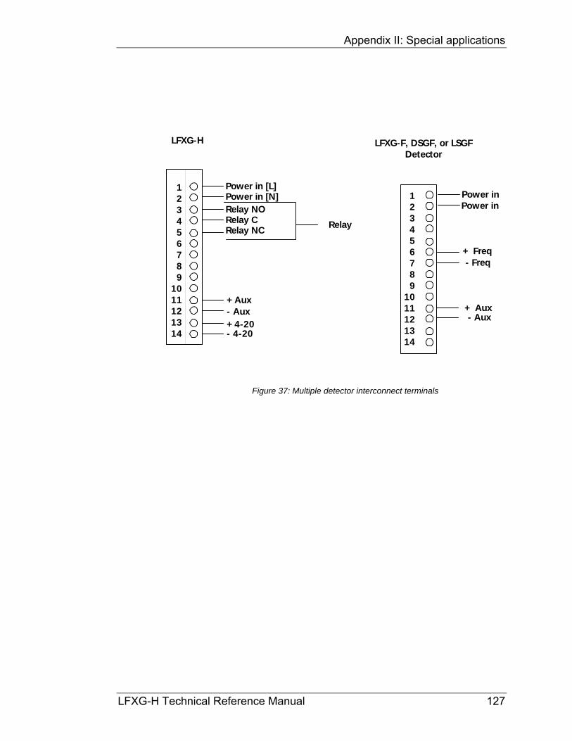
Appendix II: Special applications
LFXG-H Technical Reference Manual 127
Figure 37: Multiple detector interconnect terminals
Power in [L]
- 4-20+ 4-20- Aux+ Aux
Power in [N]Relay NORelay CRelay NC
LFXG-H
Relay
123456789
1011121314
123456789
1011121314
Power in
- Aux+ Aux
- Freq+ Freq
LFXG-F, DSGF, or LSGFDetector
Power in

Appendix II: Special applications
128 LFXG-H Technical Reference Manual
Initial settings and calibration requirements Refer to these sections of this manual for more details:
Table 24: Initial setting and calibration locations
Setting Manual heading Page Select Summation mode in Initial setup Setting up summation mode 129 Set span for total of all detectors Span settings 103 Calibrate according to guidelines in calibration chapter Initial process calibration 31
Appendix II: Special applications
LFXG-H Technical Reference Manual 129
Setting up summation mode Procedure 49: Setting up summation mode
1. From the Main menu, select Initial setup
2. From the Initial setup menu, select Auxiliary input
3. From the Auxiliary input menu, select Compensation
The compensation screen displays the current type of auxiliary input
4. From the Compensation menu, select Type
6. From the Type menu, select Summation
7. Press F4 to enter
8. If using a hand-held HART communicator, press F2 to send the settings to the transmitter.
Calibrating with multiple detectors summation The calibration procedures are the same with one or multiple detectors. The summing of the counts from multiple detectors is invisible to the user.
When setting the span, set it for the length that is the total of all the detectors.
Note: In many cases, you cannot fill or empty the process vessel for calibration. Use the following hints in these situations: With the vessel empty, open the source holder shutter to simulate low level (“set low level”) in software. Close the source holder shutter to simulate high level (“set high level” in software.)

Appendix II: Special applications
130 LFXG-H Technical Reference Manual
NORM (naturally occurring radioactive material) compensation
Products that contain natural radioactive materials (for example, radon) may require special compensation of the level measurement. The radiation emitted by the product material can interfere with the measurement, since the detector cannot differentiate between the radiation from the source and the radiation from the product.
Achieve compensation of the measurement by using a second detector that measures only the radiation emitted by the product material. A primary detector measures the process level measurement. The signal from the secondary detector is input to the primary detector. The primary detector runs an algorithm to subtract the effect of the material’s radiation from the source holder’s radiation.
Figure 38: NORM compensation system
sourceholder
frequency
Frequency outputFiberFlex LFXG-F
HART FiberFlex LFXG-Hwith S86 option
4 to 20mA

Appendix II: Special applications
LFXG-H Technical Reference Manual 131
Special drawings for NORM Compensation Ideally, identification of applications requiring NORM compensation occurs at the time of order. The end user, engineering contractor (or both) may have received certified drawings for the exact equipment ordered. Refer to the drawings along with this section of the manual.
Note: If the instruction on the drawings and this manual differ, follow the drawing instructions. They are specific to your order.
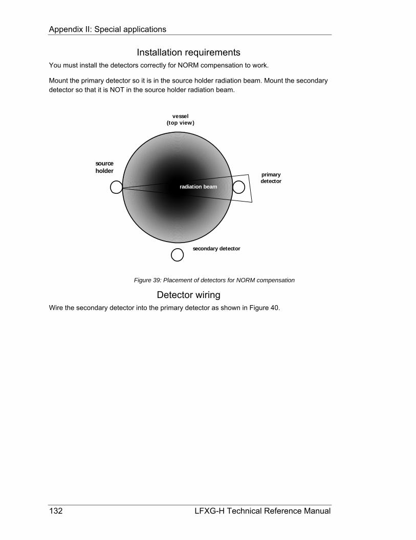
Appendix II: Special applications
132 LFXG-H Technical Reference Manual
Installation requirements You must install the detectors correctly for NORM compensation to work.
Mount the primary detector so it is in the source holder radiation beam. Mount the secondary detector so that it is NOT in the source holder radiation beam.
sourceholder
radiation beam
vessel(top view)
primarydetector
secondary detector
Figure 39: Placement of detectors for NORM compensation
Detector wiring Wire the secondary detector into the primary detector as shown in Figure 40.

Appendix II: Special applications
LFXG-H Technical Reference Manual 133
Figure 40: Interconnect— LFXG-F with LFXG-H
LFXG-H, DSG-H, or LSG-H
Power cableper local code
Power cableper local code
CENELEC ground
CENELEC ground
CENELEC ground
Housing ground
Housing ground
AuxiliaryFrequency
Input
Output signal cable
LFXG-F,DSG-F,
orLSG-F
Sensor location Control room
System architecture
PC
mA Input
DCS
M odem(optional)
Hand-held
terminal
(optional)
Output signal
Relay
PowerEarth ground
PowerEarth ground
123456789
1011121314
1234567
89
10111213
14

Appendix II: Special applications
134 LFXG-H Technical Reference Manual
Figure 41: Dual detector interconnect terminals
Power in [L]
- 4-20+ 4-20- Aux+ Aux
Power in [N]Relay NORelay CRelay NC
LFXG-H
Relay
123456789
1011121314
123456789
1011121314
Power in
- Aux+ Aux
- Freq+ Freq
LFXG-F, DSGF, or LSGFDetector
Power in

Appendix II: Special applications
LFXG-H Technical Reference Manual 135
Initial settings and calibration requirements for NORM compensation
Specific software settings and calibration procedures are required for NORM compensation.
Setting up NORM compensation Procedure 50: Setting up NORM compensation
1. From the Main menu, select Initial setup
2. From the Initial setup menu, select Auxiliary input
3. From the Auxiliary input menu, select Compensation
The compensation screen displays the current type of auxiliary input.
4. From the Compensation menu, select Type
6. From the Type menu, select Compensation
7. Press F4 to enter.
8. If using a hand-held HART communicator, press F2 to send the settings to the transmitter

Appendix II: Special applications
136 LFXG-H Technical Reference Manual
Calibrating with NORM compensation Before calibrating, make sure the NORM compensation option is set up. Refer to Procedure 50.
Note: To calibrate the NORM compensation system, you must be able to fill the vessel to the maximum level with radioactive product.

Appendix II: Special applications
LFXG-H Technical Reference Manual 137
Procedure 51: Calibrating with NORM compensation
1. Set the product level to maximum
2. Turn the source holder shutter to “OFF” (this ensures that the only radiation picked up by the detector comes from the product and not the source)
3. Perform a data collect of the primary sensor
From the Main menu, select Calibrations
From the Calibrations menu, select Data collect
Record the value of the counts from the primary data collect.
4. From the Main menu, select Initial setup
5. From the Initial setup menu, select Auxiliary input
6. From the Auxiliary input menu, select NORM
7. From the NORM menu, select Aux data collect
8. At the prompt, select Yes to take data. Record the value of the counts from the Auxiliary data collect
9. From the NORM compensation screen, select Gain. Adjust the gain value as follows:
Compare the counts from the primary and auxiliary data collects
If the auxiliary channel data collect counts are higher than the primary sensor data collect counts, adjust the NORM compensation gain down. Select Yes to accept the counts and press F4 to enter
If the auxiliary counts are lower than the primary counts, adjust the NORM compensation gain up
10. Repeat the auxiliary data collect and gain adjustment steps until the auxiliary channel counts are within +/–10% of the primary sensor counts
11. If using a hand-held HART communicator, press F2 to send the settings to the transmitter
12. Follow the procedures for performing a Two-point calibration and linearizer curve from the Calibration chapter of this manual. These procedures require changing the product level from minimum to maximum and collecting data
13. Complete the linearization and calibration with the procedures “Calculate linearity” and “Calculate calibration”. See pages 49 and 50.

Appendix II: Special applications
138 LFXG-H Technical Reference Manual
GEN2000 Local RS-485 Network
This feature supports gauging systems that require two or more measurement systems that interact to provide a single compensated measurement.
The RS-485 network has the following gauge types:
Master
Responder
The gauges use the half-duplex RS-485 communication network. The gauges transfer specific information between each other in the field with only the master gauge actually communicating with the control room.
The master gauge has the following features:
Initiates all communication on the network
Keeps a list of expected gauges on the network and cycles through each gauge requesting a response
Update the tag, count information from the responder gauges, and track the network health
The responder gauges have the following features:
Have a unique address for their reply
Have a table listing other network gauges with information that it requires and the function of that data.
Can listen to all of the responses of the other gauges, which enables each responder gauge to update the count information from other gauges (if setup to do so)
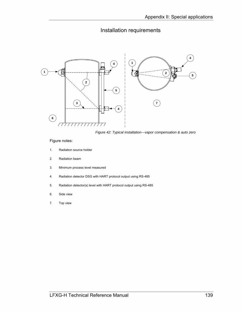
Appendix II: Special applications
LFXG-H Technical Reference Manual 139
Installation requirements
Figure 42: Typical installation—vapor compensation & auto zero
Figure notes:
1. Radiation source holder
2. Radiation beam
3. Minimum process level measured
4. Radiation detector DSG with HART protocol output using RS-485
5. Radiation detector(s) level with HART protocol output using RS-485
6. Side view
7. Top view
5
4
2
6
4
5
4
3
1
2
1
7
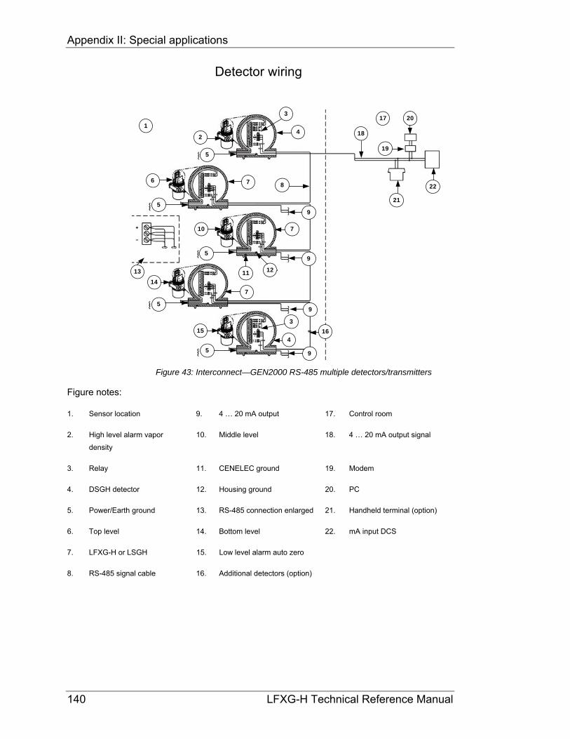
Appendix II: Special applications
140 LFXG-H Technical Reference Manual
Detector wiring
Figure 43: Interconnect—GEN2000 RS-485 multiple detectors/transmitters
Figure notes:
1. Sensor location 9. 4 … 20 mA output 17. Control room
2. High level alarm vapor
density
10. Middle level 18. 4 … 20 mA output signal
3. Relay 11. CENELEC ground 19. Modem
4. DSGH detector 12. Housing ground 20. PC
5. Power/Earth ground 13. RS-485 connection enlarged 21. Handheld terminal (option)
6. Top level 14. Bottom level 22. mA input DCS
7. LFXG-H or LSGH 15. Low level alarm auto zero
8. RS-485 signal cable 16. Additional detectors (option)
14
5
10
5
6
3
7
42
1
13
15
5
5
16
9
7
7
9
9
5
21
19
20
22
18
4
9
8
11 12
3
17

Appendix II: Special applications
LFXG-H Technical Reference Manual 141
Software To setup the RS-485 network you must have firmware version 2000.30 or 2000.30C or higher, Ohmview 2000 version 2.0.0 or higher, and a HART modem with a connection to a communication port.
The Ohmview 2000 Launcher program has the RS-485 feature. Select this feature to setup the RS-485 network, choose compensation types, and view information about the gauges.
Figure 44: Ohmview 2000 Launcher program
Click RS-485 Network to start th fi ti

Appendix II: Special applications
142 LFXG-H Technical Reference Manual
Note: If it does not connect, click Disconnect, click Exit and entirely close Ohmview 2000. Wait for 30 seconds and open the program again using the Launcher program. Select another port. After selecting the proper port with the HART modem, the program remembers the last port used and selects it again.
Figure 45: Ohmview 2000 RS-485 main screen
Select the proper Port (1-4)
Click Connect
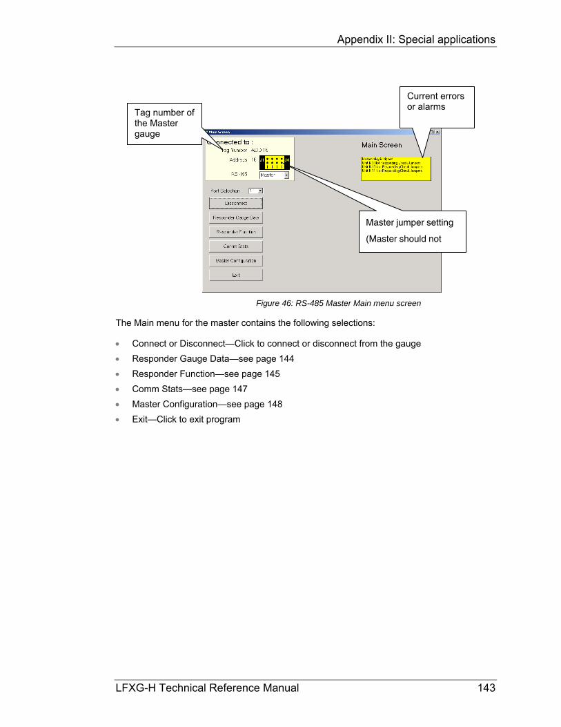
Appendix II: Special applications
LFXG-H Technical Reference Manual 143
Figure 46: RS-485 Master Main menu screen
The Main menu for the master contains the following selections:
Connect or Disconnect—Click to connect or disconnect from the gauge
Responder Gauge Data—see page 144
Responder Function—see page 145
Comm Stats—see page 147
Master Configuration—see page 148
Exit—Click to exit program
Master jumper setting (Master should not
Tag number of the Master gauge
Current errors or alarms
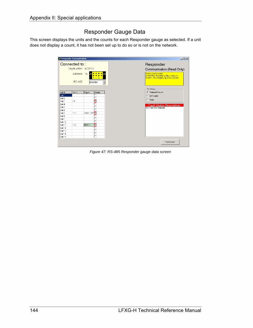
Appendix II: Special applications
144 LFXG-H Technical Reference Manual
Responder Gauge Data This screen displays the units and the counts for each Responder gauge as selected. If a unit does not display a count, it has not been set up to do so or is not on the network.
Figure 47: RS-485 Responder gauge data screen

Appendix II: Special applications
LFXG-H Technical Reference Manual 145
Responder Function Use this screen to select the function for different units.
Figure 48: RS-485 Responder Function screen
The functions available for each responder are:
Not Used
Summation
Vapor Comp
Auto Zero
External Summation

Appendix II: Special applications
146 LFXG-H Technical Reference Manual
Figure 49: Responder function pull-down menu
To change the function for a unit, perform the following steps:
Procedure 52: Changing the Responder unit function
1. Select the Function cell next to the unit number
2. From the pull-down menu, select the proper function type
3. Click Accept Function

Appendix II: Special applications
LFXG-H Technical Reference Manual 147
Communication Statistics Use this screen to view the number of times the Master unit has sent messages to the Responder units and the number of times the responder units have replied.
Figure 50: RS-485 Communication Statistics screen
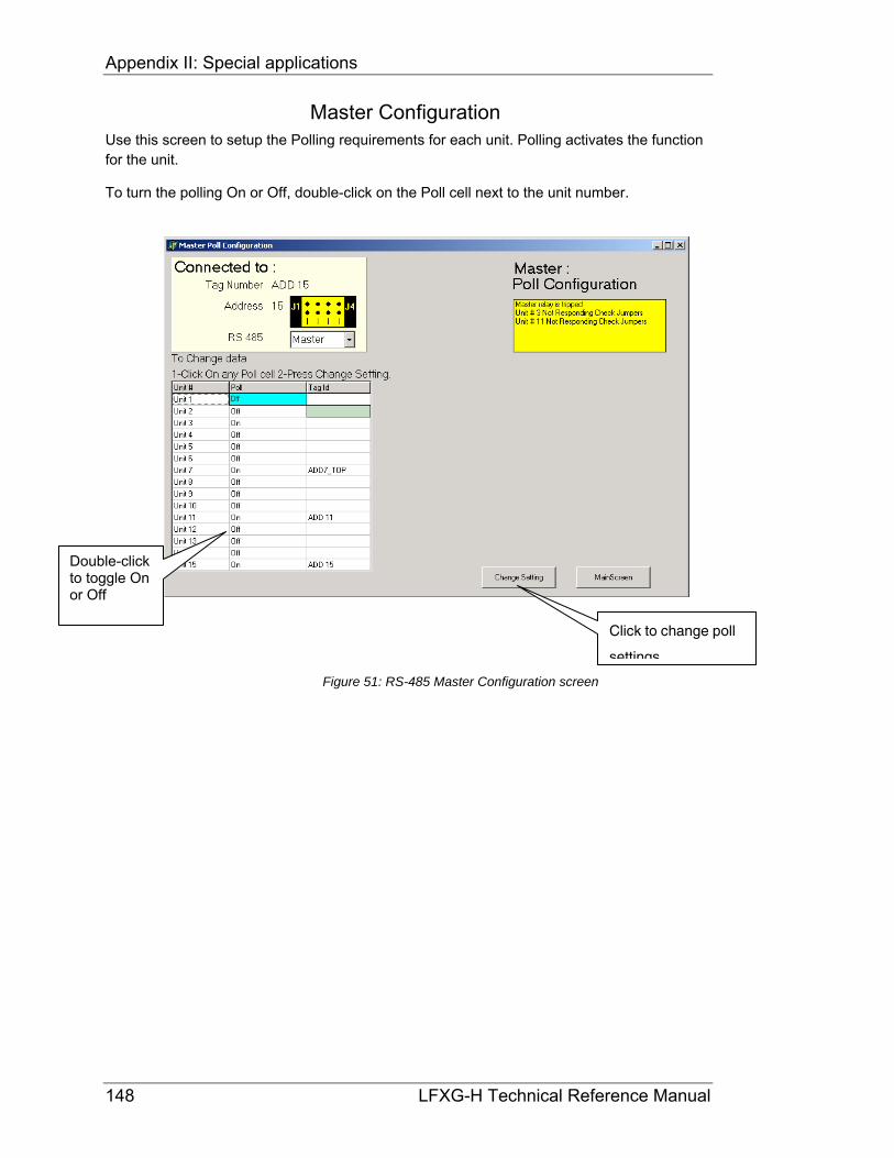
Appendix II: Special applications
148 LFXG-H Technical Reference Manual
Master Configuration Use this screen to setup the Polling requirements for each unit. Polling activates the function for the unit.
To turn the polling On or Off, double-click on the Poll cell next to the unit number.
Figure 51: RS-485 Master Configuration screen
Double-click to toggle On or Off
Click to change poll settings

Appendix II: Special applications
LFXG-H Technical Reference Manual 149
Responder Main menu To setup and test a specific responder unit, connect the HART modem jumpers anywhere along the 4 … 20 mA output.
Procedure 53: Connecting directly to a Responder
1. Open Ohmview 2000 Launcher
2. Select the communication port number that connects to the HART modem
3. Click Connect
The Responder Main Menu screen displays
Figure 52: Responder Main Screen
The following choices are available on this menu:
Responder Gauge Data (see page 144)
Responder Function (see page 145)
Connect or Disconnect –Click to connect or disconnect from gauge
Exit—Click to close program

Appendix II: Special applications
150 LFXG-H Technical Reference Manual
Initial setup Perform the following steps to set up the GEN2000 RS-485 local network:
Procedure 54: Setting up GEN2000 RS-485 local network
1. Check the wiring connections for power, network and analog output for all gauges
2. Disconnect the RS-485 network from the master gauge
3. Verify that the master gauges has no jumpers made (address F)
4. Power up the master gauge
5. Use the RS-485 configuration program to disable the RS-485 local network
From the Main Screen pull-down menu, select Off
6. Re-connect the RS-485 wiring on the master gauge
Note: Wire the Master gauge relay as the RS-485 Network Fault relay. Failure to use this relay can result in significant measurement error from incorrect compensation or no compensation
7. Confirm that all of the gauges have a unique address jumper configuration
8. Power up all network gauges
9. Confirm all hardware is functioning properly
When directly connected to a responder gauge, the jumper

Appendix II: Special applications
LFXG-H Technical Reference Manual 151
Procedure 54: Setting up GEN2000 RS-485 local network (continued)
10. Run the RS-485 configuration program and configure the master gauge to poll all of the gauges on the network
11. Verify all gauges are communicating as expected
12. Populate the master table to continuously poll all gauges
13. Enable the RS-485 local network using the configuration program – continuous communication starts
Procedure 54: Setting up GEN2000 RS-485 local network (continued)
14. Continue to monitor the RS-485 network to verify that all of the gauges are responding as expected and that the relay is not in an alarm condition
Double click on the Poll cell to toggle On
Click Change

Appendix II: Special applications
152 LFXG-H Technical Reference Manual
15. For each gauge on the RS-485 local network:
Use the RS-485 Configuration software to configure the Responder table
Verify that the Responder table contains all of the units required for the particular gauge
Verify the Responder table is updating
16. Connect to each gauge using Ohmview 2000 and setup each gauge for the particular application. Access the Ohmview 2000 electronic manual under Help for further information on setting up the gauge.

Appendix II: Special applications
LFXG-H Technical Reference Manual 153
Auto Zero feature
Use this feature with the RS-485 network to provide data to the primary level gauge. The counts feed into the level gauge from the low point indicator on the vessel. When the level gauge senses a preset threshold value, it implements the Auto Zero feature. This feature resets the zero point.
Setting up the Auto Zero feature To enable this feature using Ohmview 2000’s RS-485 Network program, you must have firmware 200030 or 30C or higher for GEN2000 instruments.

Appendix II: Special applications
154 LFXG-H Technical Reference Manual
Procedure 55: Setting up GEN2000 RS-485 local network
1. Determine the gauge and unit number for your point level indicators
2. Fill the vessel until the process is just above the low process indicator and record the count
3. Fill the vessel until the process is just below the low process indicator and record the count
4. Calculate the 50% level of the two count totals. This number is your auto zero threshold
5. Open the OHMVIEW 2000 Launcher program
6.
7.
This connects to the gauge that attaches to your HART modem
Click RS-485 NETWORK
Click Connect

Appendix II: Special applications
LFXG-H Technical Reference Manual 155
Procedure 55: Setting up GEN2000 RS-485 local network (continued)
8.
9.
10. The Auto Zero feature is enabled.
Click Responder Function
Select Responder and Select Auto Zero
Enter the Auto Zero SetPoint and click Accept Threshold
Click Accept Function

Appendix II: Special applications
156 LFXG-H Technical Reference Manual
Vapor pressure compensation
A nuclear level gauge works on the principle that the product shields the detector from the radiation beam, allowing more or less radiation to strike the detector as the product level falls and rises. For an accurate level indication, the variation in the detector output should depend only on the product level.
However, vapor pressure variations in the headspace of the vessel can cause erroneous product level indications. This is because the vapor also blocks some of the radiation. When the pressure is higher, more radiation is blocked; when the vapor pressure is lower, less is blocked. Therefore, even at the same product level, the detector can receive varying amounts of radiation, depending on the head vapor pressure.
You can compensate for this by using a point detector (model DSGH) to separately measure the radiation passing through the vapor space. This detector signal and the signal from the continuous level detector combine to eliminate the effect of the vapor pressure on the level indication.
Figure 53: Vapor compensation system
FiberFlexLFXG-F
with S85 option
frequency
4 to 20mA
DSGH
sourceholder

Appendix II: Special applications
LFXG-H Technical Reference Manual 157
Installation requirements A vapor compensation system requires two detectors: the point detector (model DSGH) to measure the vapor space, and the continuous level detector to measure the product level.
Both must be in the radiation beam from the source holder. Mount the DSGH so that it is above the highest expected product level.
Detector wiring The level detector provides a frequency signal to the DSGH. The output of the DSGH is the calibrated, vapor compensated, 4 … 20 mA signal for control and HART communication. Figure 54 illustrates the interconnection between the density gauge and the level gauges.
Figure 54: Interconnect DSGH with LFXG-H
Sensor Location
Control Room
Optional hand-held terminal
mA input
DCS
Optional modem
Output signal
PC
M od
Hand-held
Terminal
SYSTEM ARCHITECTURE
Relay
DSGH
Cenelec Ground
Housing ground
Cenelec Ground
Housing ground
Output signal cable
Power cable per local codes
PowerEarth ground
Power cable per local codes
Auxiliary frequency input
LFXG-For LSGF
PowerEarth ground

Appendix II: Special applications
158 LFXG-H Technical Reference Manual
Algorithm for vapor comp The vapor compensation algorithm adjusts the percent span based on a percent change in vapor density from a reference density. (Refer to the Calibration chapter for a complete discussion of continuous level gauge calibrations.)
Each time the gauge computes a level measurement, a new Cal low counts value calculates, which changes the percent span. The algorithm for calculating the cal low counts is:
New cal low counts=cal low counts * (1–(vc gain * % change in vapor density counts))
Where:
% change in vapor density counts=(reference counts–vapor density counts)/reference counts
Variable definitions
Reference counts Reference counts are counts from DSGH at reference pressure condition (determined during first step of calibration).
Vapor density counts Vapor density counts are counts from DSGH at current pressure condition.
VC gain VC gain is the vapor compensation gain (user enters value during calibration)

Appendix II: Special applications
LFXG-H Technical Reference Manual 159
Initial settings and calibration for vapor comp Setting up vapor compensation
Procedure 56: Setting up vapor compensation
1. Perform the following steps to set the DSGH up as a level gauge:
From the Main menu, select Advanced Fxns
From the Advanced Fxns menu, choose Select Gage type
From the Select Gage type menu, select Level
Press F2 to send to the transmitter
2. Return to the Main menu
3. Perform the following steps to select Vapor compensation:
From the Main menu, select Auxiliary input
From the Auxiliary input menu, select Compensation
From the Compensation menu, select Type
From the Type menu, select Vapor
Press F4 to enter. You return to the Compensation menu
4. Return to the Auxiliary input menu.
5. From the Auxiliary input menu, select Filter TC
6. Set the filter time constant. For best response, this value should be five seconds. If this value is too large (>10sec), the system response slows, with long settling times on the final output
7. From the Compensation menu, select Vapor
8. From the Vapor menu, select Gain
Set the Gain to 1.0
You adjust it again during the calibration procedure
9. If using a hand-held HART communicator, press F2 to send the settings to the transmitter.

Appendix II: Special applications
160 LFXG-H Technical Reference Manual
Calibrating with vapor compensation Before calibrating, make sure the vapor compensation option is set up (see Procedure 56).
Note: To calibrate the vapor pressure compensation system, you must be able to adjust both the product level and the vapor pressure.
Calibrating with vapor compensation Procedure 57: Calibrating with vapor compensation
1. Set the vapor pressure to a typical pressure (this is the reference pressure). At this point, the product level is not important, as long as the density gauge is not blocked by the product
2. From the Main menu, select Initial setup
3. From the Initial setup menu, select Auxiliary input
4. From the Auxiliary input menu, select Vapor
5. From the Vapor menu, select Aux data collect (This determines the reference counts for the vapor compensation algorithm.)
6. At the prompt, select Yes to take data.
When data collection is complete, select Yes to save the vapor pressure reference counts
7. If using a hand-held HART Communicator, press F2 to send the settings to the transmitter
8. Return to the Main menu
9. Follow the procedures for performing a Two-point calibration and linearizer curve from the Calibration chapter of this manual.
These procedures require changing the product level from minimum to maximum and collecting data
During the calibration and linearization procedure, maintain the reference pressure in the headspace
10. Complete the linearization and calibration with the procedures “Calculate linearity” and “Calculate calibration”. See pages 49 and 50
11. Set the product to the lowest possible level while at the maximum pressure

Appendix II: Special applications
LFXG-H Technical Reference Manual 161
Procedure 55: Calibrating with vapor compensation (continued)
12. Set the vapor density to its highest possible value
13. Note the level indication (it will likely be upscale)
14. From the Initial setup menu, select Auxiliary input
15. From the Auxiliary input menu, select Vapor
16. From the Vapor menu, select Gain
17. Adjust the vapor compensation gain value until the level indication reads the correct, minimum level value
18. Press F2 to send to the transmitter.

Appendix II: Special applications
162 LFXG-H Technical Reference Manual
Internal heater kit for applications requiring a –50 C rating
A heater kit option is available for the LFXG-H for applications that require a –50˚C (–58 ˚F) temperature rating. With the heater option, the internal temperature of the unit rises approximately 30 ˚C (54 ˚F) degrees.
The features of the heater are as follows:
The heater kit does not affect the functionality of the LFXG-H in any way. There is no requirement for special firmware
The factory installs the internal heater kit if you order it with the LFXG-H
Retrofits are available for previously installed equipment
Three different kits are available, one for 115VAC, one for 220VAC, and one for 24VDC. The part numbers are shown below:
Table 25: Heater kit part numbers
Heater kit power VEGA Part Number115 VAC 240723220 VAC 24072424VDC 241912
Changes to specifications The power rating changes from the specifications on page 5 of this manual when you install the heater kit on the LFXG-H.
With the installation of the heater, the maximum power consumption increases to 25W.
The unit is either 115VAC10% or 220VAC10% instead of the standard 90–270VAC range or 24VDC.
Notes
LFXG-H Technical Reference Manual 163
Appendix III: Preserving information from SmartPro to the LFXG-H
This appendix describes how to preserve information from an existing level gauge to the LFXG-H.
Preserving information from SmartPro
If you have existing Smart Pro electronics (Smart Pro or Smart Pro Pac), you can preserve information on setup and calibration from the Smart Pro electronics. This information can transfer to the new transmitter electronics, saving a great deal of time commissioning the gauge.
Note: Smart 1 and Smart 2 electronics users can preserve the information from their systems and transfer it to the HART electronics. We recommend consulting VEGA Field Service for help on your individual installation.
Note: EDS users cannot transfer information to the HART electronics. You must perform new setup and calibration procedures.
After the new electronics are installed, refer to “Appendix I: Initial Factory Setup” to enter the correct parameters. Proceed to the “Calibration” chapter for instructions to calibrate the gauge.

Appendix III: Retrofitting HART electronics
164 LFXG-H Technical Reference Manual
Use the following table to record data from the Smart Pro:
Table 26: Smart Pro data record
Smart Pro parameter Smart Pro screen/item ValueCorresponding
HART parameter
Standardize parameter 520/25 -
Standardize parameter 520/26 -
Process low value (Low sample input) 520/32 Cal low level
Process high value (High sample input) 520/33 Cal high level
Cal low counts 520/39 Counts low
Cal high counts 520/40 Counts high
Time constant 527/0 Filter
Fast response filter (chrontrol) 527/1 Threshold
Span 527/2 N/A
Output min 527/10 4 mA level
Output max 527/11 20 mA level
Linearizer curve On/Off 528/41 N/A
Low product value 528/42 Min level
High product value 528/43 Max level
Use Table 27 to record the linearizer table information. Transferring this information makes a new initial calibration procedure unnecessary. (If you prefer to do a new initial calibration, refer to the Calibration chapter of this manual for instructions.)
To calculate the new value to enter into the HART version linearizer table, divide the Smart Pro value of each point by 100. For example, if the Smart Pro value of point 2 is 630, enter 6.30 as the corresponding HART 5.0% point.

Appendix III: Retrofitting HART electronics
LFXG-H Technical Reference Manual 165
Table 27:Linearizer record
Linearizer table points
Smart Pro Screen/item Smart Pro Value
HART Linearizer table point (%span)
HART Linearizer table (Smart Pro Value 100)
0 528/0 0.0% 1 528/1 2.5% 2 528/2 5.0% 3 528/3 7.5% 4 528/4 10.0 5 528/5 12.5 6 528/6 15.0 7 528/7 17.5 8 528/8 20.0 9 528/9 22.5 10 528/10 25.0 11 528/11 27.5 12 528/12 30.0 13 528/13 32.5 14 528/14 35.0 15 528/15 37.5 16 528/16 40.0 17 528/17 42.5 18 528/18 45.0 19 528/19 47.5 20 528/20 50.0 21 528/21 52.5 22 528/22 55.0 23 528/23 57.5 24 528/24 60.0 25 528/25 62.5 26 528/26 65.0 27 528/27 67.5 28 528/28 70.0 29 528/29 72.5

Appendix III: Retrofitting HART electronics
166 LFXG-H Technical Reference Manual
Table 33: Linearizer record (continued)
Linearizer table points
Smart Pro Screen/item Smart Pro Value
HART Linearizer table point (%span)
HART Linearizer table (Smart Pro Value 100)
30 528/30 75.031 528/31 77.532 528/32 80.033 528/33 82.534 528/34 85.035 528/35 87.536 528/36 90.037 528/37 92.538 528/38 95.039 528/39 97.540 528/40 100.0

LFXG-H Technical Reference Manual 167
Appendix IV: HART menus and screens
The following charts illustrate the HART hand-held communicator menus and screens. See the “VEGA View User Manual” for illustrations of the VEGA View HART menus and screens.

Appendix IV: HART menus and screens
168 LFXG-H Technical Reference Manual
Figure 55: HART screen—Transmitter not connected
On
lin
e
No
de
vice
fou
nd
Uti
lity
Fre
qu
en
cy D
ev
ice
2 S
yste
mIn
form
atio
n
3 L
iste
n f
or
PC
HA
RT
Pro
gra
m M
en
u(T
ran
smit
ter
no
t co
nn
ect
ed
)
5 S
imu
lati
on
4 S
tora
ge
loca
tio
n
1 C
on
fig
ure
Co
mm
un
icFr
eq
ue
ncy
: n
on
eP
ress
ure
: n
on
e

Appendix IV: HART menus and screens
LFXG-H Technical Reference Manual 169
3 M
ain
men
u1
Lev
el
##
.##
%#
#.#
# m
A
2 C
ur
ou
t
1 In
itia
l set
up
2 C
alib
rati
ons
3 G
auge
sta
tus
4 A
dvan
ced
Fxns
HA
RT
scre
en f
eatu
res
(Tra
nsm
itte
r con
nect
ed)
Figure 56: HART screen—Online

Appendix IV: HART menus and screens
170 LFXG-H Technical Reference Manual
Init
ial s
etu
p
1 P
roce
ssp
aram
eter
s2
Sys
tem
par
amet
ers
3 A
larm
s4
Au
xilia
ryin
pu
t5
Vie
wse
ttin
gs
1 Pr
oces
s un
its
1 Ti
me
and
date
2 C
alp
aram
eter
s
3 Fi
lter
ing
4 Sp
ans
2 So
urce
typ
e
3 So
urce
func
tion
4 Ta
g
5 Sy
stem
info
1 Se
l rel
ayfu
ncti
on
2 M
ode
conf
igur
atio
n
1 Fi
lter
TC
2 C
ompe
nsat
ion
1 M
ax L
evel
2 M
in L
evel
3 20
mA
Lev
el
4 4m
A L
evel
Figure 57: Initial setup

Appendix IV: HART menus and screens
LFXG-H Technical Reference Manual 171
Leve
l uni
tsin ft cm m
mm % Sp
cl
Pro
cess
par
amet
ers
1 P
roce
ss u
nit
s2
Cal
par
amet
ers
3 F
ilter
ing
4 S
pan
s
1 Le
vel u
nits
1 D
ata
coll
inte
rval
##
.#
2 C
usto
m u
nits
2 W
arn
% c
alsp
an #
#.#
3 Pr
oces
s St
dco
nfig
4 St
dz in
terv
al#
##
1 Fi
lter
typ
e
2 D
ampi
ng#
.#s
1 Pr
oces
s sp
an
2 C
urre
nt
loo
psp
an
1 C
onve
rsio
n to
lngt
hU
nits
/in
#.#
##
#
1 P
roce
ss S
tdz
Type
2 D
efau
lt st
d#
.##
##
Use
Lab
sam
ple
valu
eU
se D
efau
lt va
lue
3 Fa
st c
utof
f#
.##
##
1 M
ax L
evel
#
##
.##
%2
Min
Lev
el #
.##
%
RC
Exp
Filt
erR
ect
Win
dow
Filt
er
1
4 m
A D
ensi
ty #
.##
%2
20
mA
Den
sity
##
#.#
#%
3 P
V u
nit
%
Figure 58: Process parameters
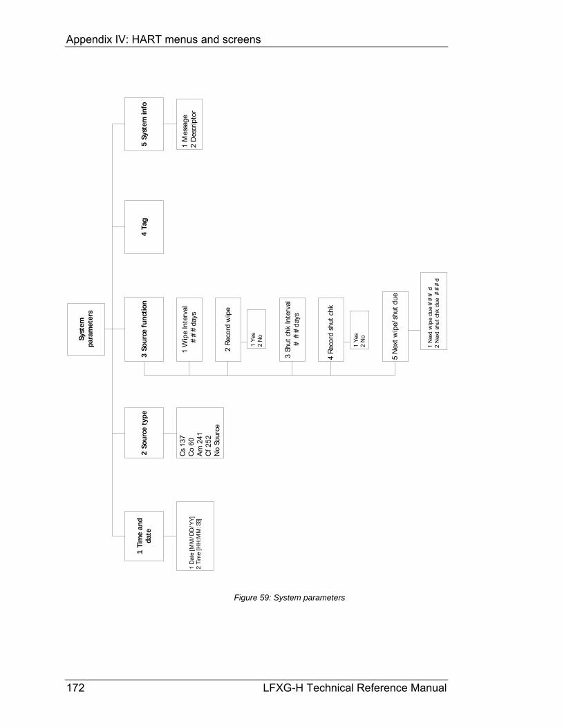
Appendix IV: HART menus and screens
172 LFXG-H Technical Reference Manual
Sy
stem
par
amet
ers
1 T
ime
and
dat
e
1 D
ate
[MM
/DD
/YY
]2
Tim
e [H
H:M
M:S
S]
2 S
ou
rce
typ
e
Cs
137
Co
60 A
m 2
41 C
f 25
2 N
o So
urce
3 S
ou
rce
fun
ctio
n
2 R
ecor
d w
ipe
5 N
ext
wip
e/sh
ut d
ue
3 Sh
ut c
hk In
terv
al#
##
days
4 R
ecor
d sh
ut c
hk
1 W
ipe
Inte
rval
##
#da
ys
1 N
ext
wip
e du
e #
##
d2
Nex
t sh
ut c
hk d
ue
##
#d
1 Y
es 2
No
1 Y
es 2
No
4 T
ag
1 M
essa
ge2
Des
crip
tor
5 S
yste
m in
fo
Figure 59: System parameters

Appendix IV: HART menus and screens
LFXG-H Technical Reference Manual 173
Ala
rms
1 S
el r
elay
fun
ctio
n2
Mo
de
con
fig
ura
tio
n
1 R
ly f
xn
2 A
nalo
g al
arm
3 Pr
oces
s re
lay
set
4 X
ray
alar
m
1 D
iagn
osti
c al
arm
1 Th
resh
old
#.#
%2
Dith
er le
vel #
.#m
A3
Cyc
le p
erio
d #
#.#
s4
Dith
er t
ime
##
.#%
Dia
gnos
tic
Gp
1
Dia
gnos
tic
Gp
2
RA
M c
orru
pt
Sens
or E
EPR
OM
co
FLA
SH c
orru
pt
Rea
l tim
e cl
ock
Sens
or t
emp
Stan
dard
ize
due
Sour
ce w
ipe
due
New
ha
rdw
are
fou
Off
/On
Off
/O
n
Off
/On
Off
/On
Off
/On
Off
/On
Off
/On
Off
/On
CPU
EEP
RO
M c
orru
Ala
rm T
ype
1
Ala
rm T
ype
2
Shut
ter
chec
k du
Proc
ess
out
of r
Off
/On
Off
/O
n
Off
/On
Off
/On
Off
/On
2 R
elay
set
poin
t #
.##
##
%
1 R
elay
act
ion
___
limit
Hig
h lim
it L
ow li
mit
1 A
larm
out
##
mA
22
mA
2
mA
Dia
gnst
ic P
roce
ss X
-ray
Figure 60: Alarms

Appendix IV: HART menus and screens
174 LFXG-H Technical Reference Manual
Au
xilia
ry in
pu
t
1 F
ilter
TC
#.#
s2
Co
mp
ensa
tio
n
1 Ty
pe
1 G
ain
#.#
##
#2
Aux
dat
a co
llect
2 N
o ite
ms
NO
RM
Vap
orSu
mm
atio
n
1 H
ardw
are
ver
#.#
#
NO
RM
Sum
mat
ion
Vap
or
No
Ite
ms
1 R
ef C
ount
s2
Aux
dat
a co
llect
3 G
ain
4 %
Ref
Cha
nge
5 A
dj C
al L
ow C
ount
s
1 H
ardw
are
Ver
#.#
#
Off
NO
RM
Vap
ort
Sum
mat
ion
Figure 61: Auxiliary input

Appendix IV: HART menus and screens
LFXG-H Technical Reference Manual 175
Vie
w s
etti
ng
s
1 M
ax L
evel
##
#.#
# %
2 M
in L
evel
#.#
#%
4 4
mA
Lev
el#
.##
%3
20
mA
Lev
el#
##
.##
%
Figure 62: View settings

Appendix IV: HART menus and screens
176 LFXG-H Technical Reference Manual
Cal
ibra
tio
ns
1 I
nit
ial c
al2
Pro
cess
std
z3
Dat
a co
llect
Cou
nts
##
.##
##
4 C
urr
ent
loo
pca
l5
Lin
eari
zer
Figure 63: Calibrations

Appendix IV: HART menus and screens
LFXG-H Technical Reference Manual 177
Init
ial c
al
1 T
wo
po
int
cal
1 Se
t C
al lo
w le
vel
2 Se
t C
al h
igh
leve
l
3 C
al r
esul
t
Set
proc
ess
to t
he lo
w c
alib
ratio
npo
int.
Tak
e da
ta?
1 N
o2
Yes
1 Y
es2
No
1 Y
es2
No
Gau
ge #
#.#
##
cnts
Cal
c #
.##
%In
put
actu
al v
alue
#.#
#%
Edit
Low
cal
poi
nt v
alue
?C
ount
s #
#.#
##
Val
ue #
.##
%D
ate
MM
/DD
/YY
Low
cal
ibra
tion
poin
tC
ount
s #
#.#
##
Low
cal
ibra
tion
valu
e #
.##
%
Set
proc
ess
to t
he h
igh
calib
ratio
npo
int.
Tak
e da
ta?
1 N
o2
Yes
Edit
Hig
h ca
l poi
nt v
alue
?C
ount
s##
.##
#V
alue
#.#
#%
Dat
e M
M/D
D/Y
Y
Hig
h ca
libra
tion
poi
ntC
ount
s #
#.#
##
Hig
h ca
libra
tion
valu
e #
.##
%
Proc
eed
with
cal
ibra
tion
calc
ulat
ion?
1 Y
es2
No
Gau
ge #
#.#
##
cnts
Cal
c #
.##
%In
put
actu
al v
alue
#.#
#%
1 S
elec
t ca
lty
pe
Figure 64: Initial cal

Appendix IV: HART menus and screens
178 LFXG-H Technical Reference Manual
Pro
cess
std
z
Gau
ge #
##
cnt
sC
alc
#.#
##
# %
Inpu
t ac
tual
val
ue #
.##
##
%
Set
proc
ess
to d
esir
ed v
alue
.Ta
ke d
ata?
1 Y
es2
No
Avg
cou
nts:
##
#
Edit
cou
nts?
1 N
o2
Yes
Figure 65: Process stdz
Dat
a co
llect
Cou
nts
##
.##
##
Set
proc
ess
to d
esir
ed v
alue
.Ta
ke d
ata?
Cou
nts
##
.##
#
1 Y
es2
No
Figure 66: Data collect
Cu
rren
t lo
op
Cal
Ente
r m
eter
val
ue #
.##
Fld
dev
outp
ut 2
0.00
mA
equ
alto
ref
eren
ce m
eter
?
Ente
r m
eter
val
ue #
.##
Fld
devi
ce o
utpu
t 4.
00m
A e
qual
to r
efer
ence
met
er?
1 Y
es2
No
1 Y
es2
No
Con
nect
ref
eren
ce m
eter
Figure 67: Current loop Cal

Appendix IV: HART menus and screens
LFXG-H Technical Reference Manual 179
Lin
eari
zer
1 S
el L
evel
lin
typ
e2
Lin
eari
zer
dat
a
Tab
le,
no
n-l
inea
rTa
ble,
line
ar
Perc
ent
cou
nt r
ange
: #
.##
#%
Perc
ent
span
: #
.##
##
%Ed
it p
erce
nt s
pan
?
2 Li
near
dat
a co
llect
1 Li
near
izer
tab
le
1 Y
es2
No
Dat
apoi
nt #
Co
unts
##
Val
ue #
.##
##
%
Val
ue #
.##
%C
ount
s##
.##
#
Pro
ceed
with
line
arit
y ca
lcu
lati
on?
1 C
olle
ct d
atap
oint
2 V
iew
/edi
tda
tapt
s
4 C
alc
linea
rity
Pro
cess
: 0.
00%
Cou
nts:
##
##
Inpu
t va
lue
in %
#.#
##
#1
Acc
ept
2 R
ejec
t
1 S
elec
tLi
nea
rize
r
1 N
o2
Yes
Per
cen
t co
unt
rang
e: #
.##
#%
Per
cen
t sp
an:
#.#
##
#%
Edit
perc
ent
span
? (e
very
2.5
% f
rom
0to
100
.00%
)
1 N
EXT
2 D
ELET
E
3 E
DIT
Dat
apoi
nt
#
Ente
r n
ew c
ount
s #
#En
ter
valu
e in
% #
#.#
##
#
3 A
dd
new
dat
a pt
Ente
r ne
w c
oun
ts #
#En
ter
valu
e in
% #
#.#
##
#
Figure 68: Linearizer

Appendix IV: HART menus and screens
180 LFXG-H Technical Reference Manual
Gau
ge
stat
us
1 R
ly s
tat
Engz
De-
engz
2 C
ur
ou
t#
#.#
#m
A3
Dia
gn
ost
ics
4 V
iew
his
tory
1 S
tdz
hist
ory
2 D
iag
nost
ichi
stor
y
Dat
e :
MM
/DD
/YY
Cou
nts:
##
Leve
l: #
.##
RA
M c
orru
ptSe
nsor
EEP
RO
M c
orru
ptFL
ASH
co
rrup
tR
eal T
ime
clo
ck f
ail
Sens
or t
emp
erat
ure
fai
lSt
anda
rdiz
e d
ueSo
urc
e w
ipe
due
New
har
dwar
e fo
und
CP
U E
EPR
OM
Ala
rm T
ype
1A
larm
Typ
e 2
Shu
tter
che
ck d
ueSe
nsor
fai
lPr
oces
s ou
t of
ran
ge
Sens
or v
olta
ge o
ut
of
spec
New
est
MM
/DD
/YY
MM
/DD
/YY
MM
/DD
/YY
MM
/DD
/YY
MM
/DD
/YY
MM
/DD
/YY
MM
/DD
/YY
MM
/DD
/YY
MM
/DD
/YY
MM
/DD
/YY
MM
/DD
/YY
MM
/DD
/YY
MM
/DD
/YY
MM
/DD
/YY
MM
/DD
/YY
Old
est
MM
/DD
/YY
MM
/DD
/YY
MM
/DD
/YY
MM
/DD
/YY
MM
/DD
/YY
MM
/DD
/YY
MM
/DD
/YY
MM
/DD
/YY
MM
/DD
/YY
MM
/DD
/YY
MM
/DD
/YY
MM
/DD
/YY
MM
/DD
/YY
MM
/DD
/YY
MM
/DD
/YY
RA
M s
tatu
sSe
nsor
EEP
RO
M s
tatu
sFL
ASH
mem
ory
stat
usR
eal t
ime
cloc
k te
stSe
nsor
tem
p p
rob
e te
stSt
anda
rdiz
e d
ue ?
Sou
rce
wip
e du
e?C
PU
EEP
RO
M s
tatu
sA
larm
Typ
e 1
Ala
rm T
ype
2Sh
utt
er c
heck
due
?N
ew h
ardw
are
foun
d?
Sens
or s
tatu
sPr
oces
s ou
t of
ran
ge?
Sens
or v
olta
ge s
tatu
s
Pass
Pass
Pass
Pass
Pass
No
No
Pass
Pass
Pass
No
No
Pass
No
Pass
Figure 69: Gauge status

Appendix IV: HART menus and screens
LFXG-H Technical Reference Manual 181
Ad
va
nce
dF
xn
s
1 P
roce
ssch
ain
2 M
in/m
ax
his
tory
3 N
ew
ha
rdw
are
4 T
est
mo
de
1 P
rim
ary
chan
ne
l
3 A
ux
chan
ne
lch
ain
2 P
roce
ssva
riab
les
7 S
ele
ct g
ag
elo
cati
6 S
ele
ct g
ag
ety
pe
5 O
the
ra
dv
an
ced
1 N
ew
CP
Ub
oar
d
3 N
o n
ew
har
dw
are
2 N
ew
se
nso
r
1 m
A t
est
mo
de
3 A
ux
In
p t
est
mo
de
2 S
en
sor
test
mo
de
4 R
ela
y te
stm
od
e4
Har
dw
are
ver
5 T
em
pe
ratu
rete
st
1 S
en
sor
volt
age
3 F
irm
war
e
ver
2 P
oll
add
ress
5 C
PU
Se
rial
No
.
7 V
iew
Te
mp
coe
ffs
6 S
en
sor
Seri
al
No
.
Sele
ct g
age
typ
eSe
lect
gag
elo
cati
on
Figure 70: Advanced Fxns

Appendix IV: HART menus and screens
182 LFXG-H Technical Reference Manual
Pro
cess
ch
ain
1 P
rim
ary
chan
nel
2 P
roce
ssva
riab
les
3 A
ux
chan
nel
chai
n
Aux
raw
cou
nts
Filt
coun
ts0 0
1 Te
mp
2 Se
nsor
cnt
s3
TC c
ount
s4
Raw
cou
nts
5 A
dj c
ount
s6
SD c
ount
s7
Stdz
cnt
s8
%C
nt
rang
e9
% o
f sp
anR
aw L
evel
Unc
omp
Lvl
Leve
l
##
.# d
eg C
##
##
##
##
##
##
##
.##
#.#
##
##
#.#
##
##
#.#
##
##
.##
##
%
1 C
ount
s lo
w2
Cou
nts
high
3 M
ax L
evel
4 M
in L
evel
5 Te
mp
Com
p ga
in6
Uni
form
ity g
ain
7 So
urce
Dec
ay g
ain
8 St
dz g
ain
9 H
V S
ettin
g
##
##
##
##
##
##
.##
##
%#
.##
##
%#
##
##
.##
##
#.#
##
##
##
#
Figure 71: Process chain

Appendix IV: HART menus and screens
LFXG-H Technical Reference Manual 183
Min
/max
his
tory
1 T
emp
min
/max
2 Se
nsor
min
/max
3 A
ux in
min
/max
4 R
eset
min
/max
5 La
st r
eset
MM
/DD
/YY
Figure 72: Min/max history

Appendix IV: HART menus and screens
184 LFXG-H Technical Reference Manual
New
har
dw
are
1 N
ew C
PU
bo
ard
1 N
o2
Yes
1 N
o2
Yes
1 N
o2
Yes
Ver
ify
new
CP
U b
oard
inst
alle
d
3 N
o n
ewh
ard
war
e2
New
sen
sor
Do
you
wan
t to
rec
onci
le d
iffe
renc
es?
Ver
ify
new
sen
sor
inst
alle
d
Figure 73: New hardware

Appendix IV: HART menus and screens
LFXG-H Technical Reference Manual 185
Test
mo
de
1 m
A O
ut
test
mo
de
2 Ex
it m
Ate
st m
ode
1 En
ter
mA
test
mod
e 1 Y
es2
No
1 Y
es2
No
1 A
ux In
p te
stm
ode
1 En
ergi
zere
lay
1 E
nter
Tem
p. t
est
Ou
tpu
t cu
rren
t =
##
.##
Adj
ust
curr
ent?
1 E
nter
tes
tm
ode
2 S
enso
r te
stm
od
e4
Rel
ay t
est
mo
de
3 A
ux
Inp
tes
tm
od
e5
Tem
per
atu
rete
st
Raw
co
unts
= #
#A
djus
t co
unt
s?
Inpu
t ne
w c
oun
ts#
#
Thi
s w
ill e
xit
test
mod
e.Ex
it?
Out
put
curr
ent
=#
.##
Adj
ust
curr
ent?
Star
t m
ode
/sen
d n
ew d
ata?
Inp
ut n
ew o
utp
ut
curr
ent
##
.##
1 Y
es2
No
1 Y
es2
No
1 Y
es2
No
1 Y
es2
No
1 Y
es2
No
1 Y
es2
No
1 Y
es2
No
Wan
t to
exi
t ch
ang
e lo
op?
1 Y
es2
No
Star
t m
ode
/sen
d n
ew d
ata?
1 Y
es2
No
Aux
cou
nts
= #
Ad
just
co
unts
?
1 Y
es2
No
Raw
cou
nts
= #
Adj
ust
cou
nts?
Star
t m
ode
/sen
d n
ew d
ata?
1 Y
es2
No
3 Ex
it r
elay
tes
t
2 D
e-en
ergi
zere
lay
2 Ex
it a
uxte
st m
ode
2 Ex
it T
emp.
test
mod
e2
Exit
tes
tm
ode
This
will
exi
t te
st m
ode.
Exit?
This
will
exi
t te
st m
ode.
Exit?
Thi
s w
ill e
xit
test
mo
de.
Exit
?
Aux
cou
nts
= #
Ad
just
co
unts
?C
urr
ent
tem
per
atu
re =
##
.#
Inp
ut n
ew a
ux c
oun
ts#
.#
Send
new
tem
per
atu
re?
#.#
1 Y
es2
No
1 Y
es2
No
Figure 74: Test mode

Appendix IV: HART menus and screens
186 LFXG-H Technical Reference Manual
Oth
erad
van
ced
1 S
enso
rvo
ltag
e#
##
#V
2 P
oll
add
r#
4 H
ard
war
e ve
r#
.##
3 F
irm
war
e ve
r#
.##
5 C
PU
Ser
ial
No
.A
AA
AA
#A
A
1 V
iew
Tem
p. C
oefs
2 T0
Coe
f #
.##
##
##
2 T1
Coe
f #
.##
##
##
3 T2
Coe
f #
4 T3
Coe
f #
6 S
enso
r Se
rial
No
.A
AA
AA
#A
A
7 V
iew
Tem
pco
efs
Figure 75: Other advanced

Appendix IV: HART menus and screens
LFXG-H Technical Reference Manual 187
Sele
ct g
age
typ
e
CA
UTI
ON
Cha
ngin
g ga
ge t
ype
fund
amen
tally
cha
nges
gage
ope
rati
on.
See
man
ual b
efor
e pr
oced
ing.
Leve
lD
ensi
ty
Sele
ct g
age
type
Figure 76: Select gage type
Sele
ct g
age
loca
ti
CA
UTI
ON
Cha
ngin
g ga
ge lo
cati
on f
unda
men
tally
cha
nges
gage
ope
rati
on.
See
man
ual b
efor
e pr
oced
ing.
Loca
lR
emot
e
Sele
ct g
age
loca
tion
Figure 77: Select gage location

Appendix IV: HART menus and screens
188 LFXG-H Technical Reference Manual
Notes

LFXG-H Technical Reference Manual 189
Index % count range, 54 % process span, 54 20mA Level, 105 4mA Level, 105 active area
between mounting brackets, 22 Adj counts, 54 Advanced Functions, 53 Advanced Fxns, 53 alarm
analog alarm, 113 setup, 110
Alarm out 2 mA alarm setup, 113
Alarm out 22 mA alarm setup, 113
Ammeter, 33 analog alarm
selecting 2mA or 22mA, 113 analog output. See current loop output applications, 6 Auto Zero feature, 153 Aux channel chain, 56 Aux input test, 61 Aux min/max, 56 Aux raw counts, 56 auxiliary input, 119 Auxiliary input test mode, 65 Cable
length, 25 size, 25
Calculate linearity, 49 calibration
current loop (analog output), 32 initial simple method of, 37 initial standard method of, 35
Calibration, 31 initial, 44 results, 50 standard or simple, 34
Calibrationtable, 45 CE compliance, 25 Changes
process vessel, 51 Commissioning, 27 Communication, 26 Conduit, 26 Counts high, 55 Counts low, 55 CPU, 58
new board, 59 CPU board
jumpers, 81 replacing, 92
CPU EEPROM corrupt, 60 alarm acknowledge, 75 alarm setup, 111 in diagnostic history, 74
CPU EEPROM status diagnostics check, 75
CPU serial number, 68 current loop
calibrating on the bench, 19 calibration, 32 power source or sink mode, 81 span, 105
current loop output test mode, 61 custom units, 98 Customer Order (C.O.) Number, 7
required for repairs, 94 Cycle period, 116
alarm setup, 117 Damping, 102 Data collect, 43 Data collection interval, 99
using data collect on sample to check interval, 43 Date, 106 Default standardize level, 100 Descriptor
user defined in System information, 109 device description, 12 diagnostic alarm
setting relay as, 112 diagnostic history, 74 Dither level, 116
alarm setup, 117 Dither time, 117
alarm setup, 117 drawings, 123 EEPROM, 58
corrupt, 59 EEPROM corruption repair, 60 Equipment
wiring, 23 Fast response cutoff, 102 Field service. See Ohmart Customer Service Field Service checklist, 30 filtering, 101
damping, 102 fast response cutoff, 102 of auxiliary input, 119 RC, 101 rectangular window, 102
Firmware version, 68 Flash corrupt
alarm setup, 111 FLASH corrupt
in diagnostic history, 74 FLASH corrupt LED pattern, 83 gain, 47 Gauge
moving, 51 repeatability, 43
GEN2000 Local RS-485 Network, 138 grounding, 23 hand-held terminal, 11 Hardware version, 68 HART, 11 HART Communicator, 11 HART HHT screens and menus, 167

Index
190 LFXG-H Technical Reference Manual
HART load resistance, 11 Heater, 162 High level
setting, 47 High voltage
displayed in process chain, 56 History information, 74 hot spot key, 53 initial calibration
new required, 51 theory of, 39
input filter, 120 jumpers, 81 Level instead of density is indicated. See
Select gauge type Licenses
General and Specific, 28 linear table, 42 Linearity, 49 linearizer
linear table, 42 non-linear table, 42
Linearizer choosing, 42
Linearizer record, 165 Linearizer table
new, 49 Linearizer table data, 48 Low level
setting, 46 low temperature application, 162 mA output test, 61 Max and min history
reset, 57 Max level, 55 Max Level, 39
entry in initial setup, 104 Measurement span
new, 51 Message
user defined in System information, 109 milliamp output test mode, 61 Min level, 55 Min Level, 39
entry in initial setup, 104 Min/Max history, 56 New hardware
advanced function, 58 New hardware found
alarm acknowledge, 76 alarm setup, 111 diagnostics check, 76 in diagnostic history, 74
New hardware found message responses to, 59
Next wipe/shutter check due, 108 No device found message, 83 non-linear table, 42 NORM
drawings, 131 NORM comp
setting up, 135 differences with communicator, 14, 15
Ohmview 2000, 11 Output current, 25
percent count range, 54 percent process span, 54 poll address, 68 Poll address, 68 Power
AC, 25 DC, 25
Primary channel, 53 process alarm
setting relay as, 115 Process alarm, 78 Process alarm override switch, 26 Process application
new, 51 Process chain, 53 Process out of measurement range
alarm setup, 111 Process out of range
alarm acknowledge, 76 diagnostics check, 76 in diagnostic history, 74
Process standardize type, 100 Process variables, 55 Process vessel
build up or erosion, 51 Process vessel changes, 51 PV (process value), 55 RAM corrupt
alarm acknowledge, 75 alarm setup, 111 in diagnostic history, 74
RAM status diagnostics check, 75
Raw counts, 53 Raw level, 55 Real time clock fail
alarm acknowledge, 75 alarm setup, 111 in diagnostic history, 74
Real time clock test diagnostics check, 75
Record shutter check, 108 Record wipe, 107 Relay, 114 Relay action limit—High limit
alarm setup, 114 Relay action limit—Low limit
alarm setup, 114 relay settings
diagnostic alarm, 112 process alarm, 115 x-ray alarm, 118
Relay test, 61 Relay test mode, 66 repairs
material return authorization (MRA) number, 95 returning equipment to Ohmart, 94
Reset last date, 56
Results calibration, 50
RS-485 Communication Statistics, 147 Master configuration, 148 responder function, 146

Appendix IV: HART menus and screens
LFXG-H Technical Reference Manual 191
Responder menu, 149 RS-485 Network, 153
responder function, 145 responder gauge data, 144 setting up, 150
RS-485 network wiring, 141 RS-485 software, 141 SD (source decay) counts, 54 Select gage location, 70 Select Gage Location, 70 Select gage type, 70 Select gauge type, 70 Sensor counts, 53 Sensor EEPROM corrupt, 60
alarm acknowledge, 75 alarm setup, 111 in diagnostic history, 74
Sensor EEPROM status diagnostics check, 75
sensor fail in diagnostic history, 74
Sensor fail alarm acknowledge, 76 alarm setup, 111
Sensor high voltage fail alarm acknowledge, 76 alarm setup, 111
Sensor min/max, 56 Sensor serial number, 68 Sensor status
diagnostics check, 76 sensor temp probe
alarm acknowledge, 75 Sensor temp probe test
diagnostics check, 75 sensor temperature
alarm setup, 111 in diagnostic history, 74
Sensor test, 61 Sensor test mode, 63 sensor voltage, 68 Sensor voltage, 68 Sensor voltage out of spec
in diagnostic history, 74 Sensor voltage status
diagnostics check, 76 serial numbers, 68 Setting
zero, 46 shutter check
alarm setup, 111 frequency, 89 recording when complete, 89 setting the interval, 107
shutter check due alarm acknowledge, 76
Shutter check due diagnostics check, 76 in diagnostic history, 74
Shutter check interval, 107 Smart Pro
transferring data from, 163 Smart Pro data record, 164 Source decay gain
displayed in process chain, 55
source holder, 9 Source holder
new, 51 source holder lock, 27 Source type, 107 source wipe
alarm setup, 111 frequency, 89 recording when complete, 89 setting the interval, 107
source wipe due alarm acknowledge, 75 diagnostics check, 75 in diagnostic history, 74
span current loop (analog output), 105 process, 104 setup, 104 with multiple detectors, 129
spare parts, 90 frequency output detectors, 124
specifications heater kit changes, 162 LFXG-H, 5
Standardization auto reminder, 51 periodic, 51
standardize due alarm acknowledge, 75 alarm setup, 111 diagnostics check, 75 in diagnostic history, 74
standardize gain, 51 Standardize gain, 51
displayed in process chain, 55 Standardize interval, 100 Standardizing
gauge, 52 Status Error, 61 Stdz (standardize) counts, 54 storage, 3 System parameters, 106 Tag, 108 TC (temperature compensated )counts, 53 Temp (sensor temperature), 53 Temp comp gain, 55 temperature coefficients, 68 Temperature test, 61 Temperature test mode, 67 Terminal, 25 Terminals
jumpers, 25 Test modes, 61 Threshold, 116
alarm setup, 117 Time, 106 time and date
failure after extended power-down, 106 re-set if extended power down, 19
Uncompensated level, 55 Uniformity gain, 55 units, 98 vapor compensation
calibrating, 160 setting up, 159

Index
192 LFXG-H Technical Reference Manual
Vapor compensation, 158 installation requirements, 157
Vapor Compensation, 156 VEGA Customer Service, 7
Field Service, 7 VEGA Field Service, 1, 94 VEGAView, 11 VEGA View software
VEGA View Software, 13, 15 version numbers, 68 vessel agitators effect, 20 View settings screen, 32 Wipe interval, 107 x-ray alarm, 78
setting parameters, 117 setting relay as, 118

VEGA Americas, Inc.4170 Rosslyn DriveCincinnati, Ohio 45209 USAPhone: 1.513.272.0131Fax: 1.513.272.0133E-mail: [email protected]
31401-US-110301Subject to change without prior notice
© VEGA Americas, Inc. Cincinnati, Ohio, USA 2011
All statements concerning scope of delivery, application, practical use, and operating conditions of the sensors and processing systems correspond to the information available at the time of printing.