Embed Size (px)
Citation preview
GE Medical Systems
TechnicalPublications
Direction 2204858Revision 1
LOGIQ 500 V/R 4.00CONFORMANCE STATEMENTfor DICOM
Copyright 2003 By General Electric Co.
Do not duplicate

GE Medical Systems

LOGIQ 500 V/R 4.00GE MEDICAL SYSTEMS CONFORMANCE STATEMENTDIRECTION DIRECTION 2204858 REV 1
i
THIS PAGE LEFT INTENTIONALLY BLANK
LOGIQ 500 V/R 4.00GE MEDICAL SYSTEMS CONFORMANCE STATEMENTDIRECTION DIRECTION 2204858 REV 1
i
TABLE OF CONTENTS
1. INTRODUCTION 1-1
1.1. OVERVIEW 1-1
1.2. OVERALL DICOM CONFORMANCE STATEMENT DOCUMENT STRUCTURE 1-1
1.3. INTENDED AUDIENCE 1-3
1.4. SCOPE AND FIELD OF APPLICATION 1-3
1.5. IMPORTANT REMARKS 1-4
1.6. REFERENCES 1-4
1.7. DEFINITIONS 1-5
1.8. SYMBOLS AND ABBREVIATIONS 1-5
2. NETWORK CONFORMANCE STATEMENT 2-1
2.1. INTRODUCTION 2-1
2.2. IMPLEMENTATION MODEL 2-1
2.3. AE SPECIFICATIONS 2-4
2.4. COMMUNICATION PROFILES 2-9
2.5. EXTENSIONS / SPECIALIZATIONS / PRIVATIZATIONS 2-10
2.6. CONFIGURATION 2-10
2.7. SUPPORT OF EXTENDED CHARACTER SETS 2-11
3. ULTRASOUND (US) INFORMATION OBJECT IMPLEMENTATION 3-1
3.1. INTRODUCTION 3-1
3.2. US IOD IMPLEMENTATION 3-1
3.3. US ENTITY-RELATIONSHIP MODEL 3-1
3.4. IOD MODULE TABLE 3-3
3.5. INFORMATION MODULE DEFINITIONS 3-4
4. SC INFORMATION OBJECT IMPLEMENTATION 4-1
LOGIQ 500 V/R 4.00GE MEDICAL SYSTEMS CONFORMANCE STATEMENTDIRECTION DIRECTION 2204858 REV 1
ii
4.1. INTRODUCTION 4-1
4.2. SC IOD IMPLEMENTATION 4-1
4.3. SC ENTITY-RELATIONSHIP MODEL 4-1
4.4. IOD MODULE TABLE 4-3
4.5. INFORMATION MODULE DEFINITIONS 4-4
5. PRINT MANAGEMENT SOP CLASS DEFINITION 5-1
5.1. INTRODUCTION 5-1
5.2. BASIC PRINT MANAGEMENT META SOP CLASSES 5-1
5.3. PRINT MANAGEMENT SOP CLASS DEFINTIONS 5-2
5.4. PRINT MANAGEMENT IODS 5-6
5.5. INFORMATION MODULE DEFINITIONS 5-7
LOGIQ 500 V/R 4.00GE MEDICAL SYSTEMS CONFORMANCE STATEMENTDIRECTION DIRECTION 2204858 REV 1
1-1
1. INTRODUCTION
1.1. OVERVIEW
This DICOM Conformance Statement is divided into Sections as described below:
Section 1 (Introduction), which describes the overall structure, intent, andreferences for this Conformance Statement
Section 2 (Network Conformance Statement), which specifies the GEMSequipment compliance to the DICOM requirements for the implementation ofNetworking features.
Section 3 (Ultrasound Information Object Implementation), which specifies theGEMS equipment compliance to the DICOM requirements for the implementationof an Ultrasound Information Object.
Section 4 (Secondary Capture Information Object Implementation), which specifiesthe GEMS equipment compliance to DICOM requirements for the implementationof a Secondary Capture Information Object.
Section 5 (Print Management Implementation), which specifies the GEMSequipment compliance to DICOM requirements for the implementation of the BasicPrint Meta SOP Classes (Gray and Color).
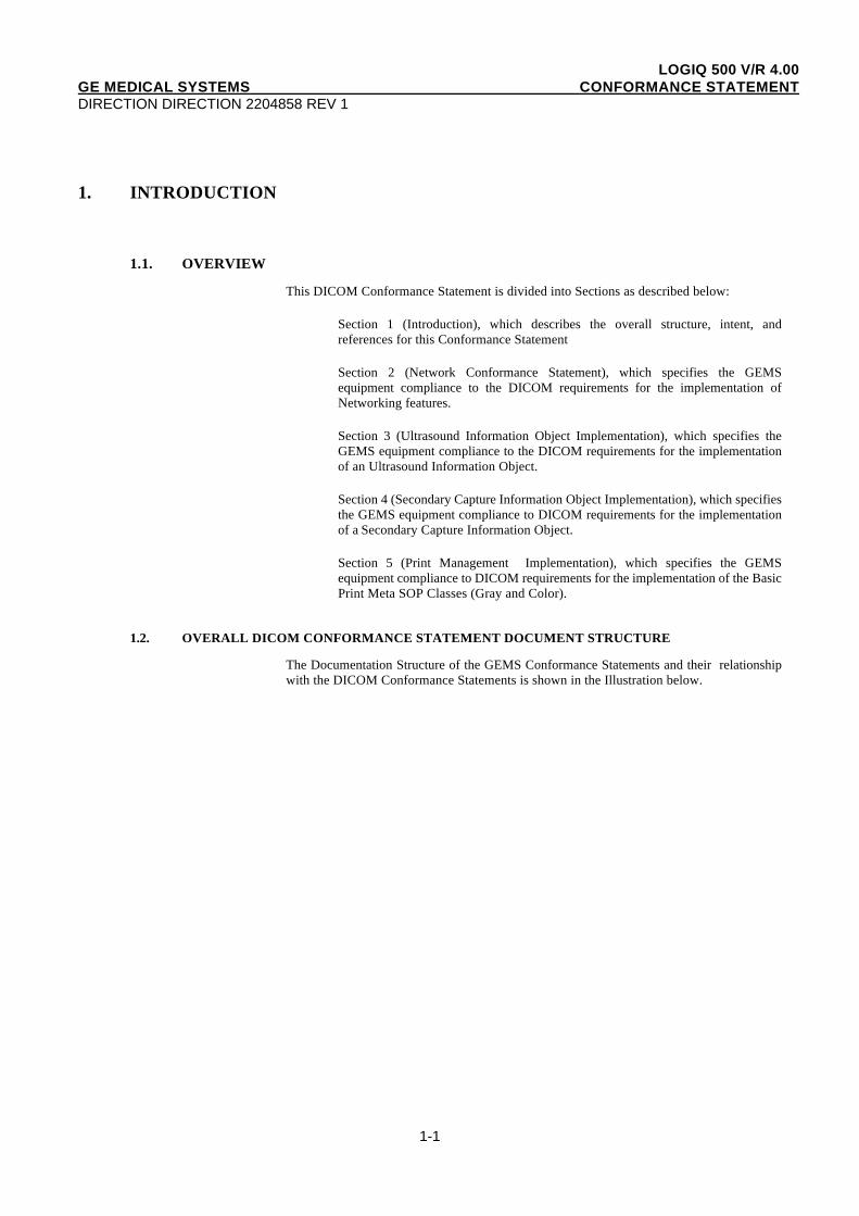
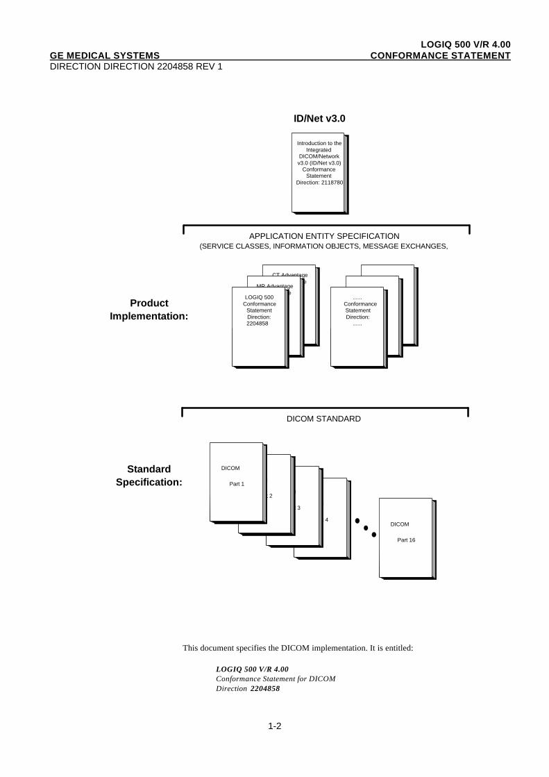
1.2. OVERALL DICOM CONFORMANCE STATEMENT DOCUMENT STRUCTURE
The Documentation Structure of the GEMS Conformance Statements and their relationshipwith the DICOM Conformance Statements is shown in the Illustration below.
LOGIQ 500 V/R 4.00GE MEDICAL SYSTEMS CONFORMANCE STATEMENTDIRECTION DIRECTION 2204858 REV 1
1-2
Introduction to theIntegrated
DICOM/Networkv3.0 (ID/Net v3.0)
ConformanceStatement
Direction: 2118780
DICOM
Part 4
DICOM
Part 3
DICOM
Part 2
DICOM
Part 1
DICOM
Part 16
ID/Net v3.0
APPLICATION ENTITY SPECIFICATION(SERVICE CLASSES, INFORMATION OBJECTS, MESSAGE EXCHANGES,ETC.)
DICOM STANDARD
ProductImplementation:
StandardSpecification:
CT AdvantageConformance
StatementDirection:
MR AdvantageConformance
StatementDirection:
LOGIQ 500Conformance
StatementDirection:2204858
...... Conformance
StatementDirection:
......
This document specifies the DICOM implementation. It is entitled:
LOGIQ 500 V/R 4.00Conformance Statement for DICOMDirection 2204858
LOGIQ 500 V/R 4.00GE MEDICAL SYSTEMS CONFORMANCE STATEMENTDIRECTION DIRECTION 2204858 REV 1
1-3
This DICOM Conformance Statement documents the DICOM Conformance Statementand Technical Specification required to interoperate with the GEMS network interface.Introductory information, which is applicable to all GEMS Conformance Statements, isdescribed in the document:
Introduction to the Integrated DICOM/Network v3.0 (ID/Net v3. 0)Conformance StatementDirection: 2118780.
This Introduction familiarizes the reader with DICOM terminology and general concepts. Itshould be read prior to reading the individual products' GEMS Conformance Statements.
The GEMS Conformance Statement, contained in this document, also specifies the LowerLayer communications which it supports (e.g., TCP/IP). However, the TechnicalSpecifications are defined in the DICOM Part 8 standard.
For more information including Network Architecture and basic DICOM concepts, pleaserefer to the Introduction.
For the convenience of software developers, there is "collector" Direction available. Byordering the collector, the Introduction described above and all of the currently publishedGEMS Product Conformance Statements will be received. The collector Direction is:
ID/Net v3.0 Conformance StatementsDirection: 2117016
For more information regarding DICOM, copies of the Standard may be obtained onthe Internet at http://medical.nema.org. Comments on the standard may be addressed to:
DICOM SecretariatNEMA1300 N. 17th Street, Suite 1847Rosslyn, VA 22209 USA
1.3. INTENDED AUDIENCE
The reader of this document is concerned with software design and/or system integrationissues. It is assumed that the reader of this document is familiar with the DICOMStandards and with the terminology and concepts which are used in those Standards.
If readers are unfamiliar with DICOM terminology they should first refer to thedocument listed below, then read the DICOM Standard itself, prior to reading thisDICOM Conformance Statement document.
Introduction to the Integrated DICOM/Network v3.0 (ID/Net v3.0)Conformance StatementDirection: 2118780
1.4. SCOPE AND FIELD OF APPLICATION
It is the intent of this document, in conjunction with the Introduction to the IntegratedDICOM/Network v3.0 (ID/Net v3.0) Conformance Statement, Direction: 2118780, to providean unambiguous specification for GEMS implementations. This specification, called aConformance Statement, includes a DICOM Conformance Statement and is necessary toensure proper processing and interpretation of GEMS medical data exchanged using DICOM.The GEMS Conformance Statements are available to the public.
LOGIQ 500 V/R 4.00GE MEDICAL SYSTEMS CONFORMANCE STATEMENTDIRECTION DIRECTION 2204858 REV 1
1-4
The reader of this DICOM Conformance Statement should be aware that different GEMSdevices are capable of using different Information Object Definitions. For example, a GEMSCT Scanner may send images using the CT Information Object, MR Information Object,Secondary Capture Object, etc.
Included in this DICOM Conformance Statement are the Module Definitions which define alldata elements used by this GEMS implementation. If the user encounters unspecified privatedata elements while parsing a GEMS Data Set, the user is well advised to ignore those dataelements (per the DICOM standard). Unspecified private data element information issubject to change without notice. If, however, the device is acting as a "full fidelity storagedevice", it should retain and re-transmit all of the private data elements which are sent byGEMS devices.
1.5. IMPORTANT REMARKS
The use of these DICOM Conformance Statements, in conjunction with the DICOMStandards, is intended to facilitate communication with GE imaging equipment. However, byitself, it is not sufficient to ensure that inter-operation will be successful. The user (oruser's agent) needs to proceed with caution and address at least four issues:
• Integration - The integration of any device into an overall system of interconnecteddevices goes beyond the scope of standards (DICOM), and of this introduction andassociated DICOM Conformance Statements when interoperability with non-GEequipment is desired. The responsibility to analyze the applications requirements and todesign a solution that integrates GE imaging equipment with non–GE systems is theuser's responsibility and should not be underestimated. The user is strongly advised toensure that such an integration analysis is correctly performed.
• Validation - Testing the complete range of possible interactions between any GE deviceand non–GE devices, before the connection is declared operational, should not beoverlooked. Therefore, the user should ensure that any non–GE provider accepts fullresponsibility for all validation required for their connection with GE devices. Thisincludes the accuracy of the image data once it has crossed the interface between the GEimaging equipment and the non–GE device and the stability of the image data for theintended applications.
Such a validation is required before any clinical use (diagnosis and/or treatment) isperformed. It applies when images acquired on GE imaging equipment areprocessed/displayed on a non-GE device, as well as when images acquired on non-GEequipment is processed/displayed on a GE console or workstation.
• Future Evolution - GE understands that the DICOM Standard will evolve to meet theuser's growing requirements. GE is actively involved in the development of the DICOMStandard. DICOM will incorporate new features and technologies and GE mayfollow the evolution of the Standard. The GEMS protocol is based on DICOM asspecified in each DICOM Conformance Statement. Evolution of the Standard mayrequire changes to devices which have implemented DICOM. In addition, GEreserves the right to discontinue or make changes to the support ofcommunications features (on its products) reflected on by these DICOMConformance Statements. The user should ensure that any non–GE provider, whichconnects with GE devices, also plans for the future evolution of the DICOM Standard.Failure to do so will likely result in the loss of function and/or connectivity as theDICOM Standard changes and GE Products are enhanced to support these changes.
• Interaction - It is the sole responsibility of the non–GE provider to ensure thatcommunication with the interfaced equipment does not cause degradation of GEimaging equipment performance and/or function.
1.6. REFERENCES
LOGIQ 500 V/R 4.00GE MEDICAL SYSTEMS CONFORMANCE STATEMENTDIRECTION DIRECTION 2204858 REV 1
1-5
A list of references which is applicable to all GEMS Conformance Statements is included inthe Introduction to the Integrated DICOM/Network v3.0 (ID/Net v3.0) ConformanceStatement, Direction: 2118780 .
The information object implementation refers to DICOM PS 3.3 (Information ObjectDefinition).and Supplement 5 (Ultrasound Application Profile, IOD, and Transfer SyntaxExtensions).
1.7. DEFINITIONS
A set of definitions which is applicable to all GEMS Conformance Statements is included inthe Introduction to the Integrated DICOM/Network v3.0 (ID/Net v3.0) ConformanceStatement, Direction: 2118780 .
1.8. SYMBOLS AND ABBREVIATIONS
A list of symbols and abbreviations which is applicable to all GEMS ConformanceStatements is included in the Introduction to the Integrated DICOM/Network v3.0 (ID/Netv3.0) Conformance Statement, Direction: 2118780 .
LOGIQ 500 V/R 4.00GE MEDICAL SYSTEMS CONFORMANCE STATEMENTDIRECTION DIRECTION 2204858 REV 1
2-1
2. NETWORK CONFORMANCE STATEMENT
2.1. INTRODUCTION
This section of the DICOM Conformance Statement specifies the compliance to DICOMconformance requirements for the relevant Networking features on this GEMS product. Notethat the format of this section strictly follows the format defined in DICOM Standard PS 3.2(Conformance). Please refer to that part of the standard while reading this section.
The LOGIQ 500 is an ultrasound scanning device that provides the user with the capability to transfer digital ultrasound images over a LAN to remote devices for archiving and/orprinting, using DICOM.
LOGIQ 500 DICOM is an optional software product which supports DICOM andpermits interoperability across equipment produced by different vendors that also utilizeDICOM services. On any given network, LOGIQ 500 can send images to multiplearchive/review stations (PACS) and printers. The network is easily configured at any time,but is normally done at software installation by a GEMS Field Engineer. LOGIQ 500 has oneapplication entity (AE) that provides all DICOM services that are required to support the“send”, “print” and “verify” services.
2.2. IMPLEMENTATION MODEL
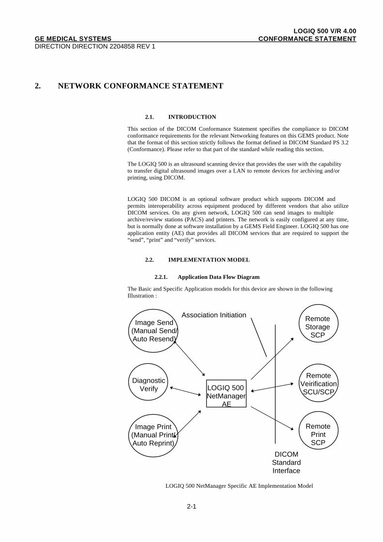
2.2.1. Application Data Flow Diagram
The Basic and Specific Application models for this device are shown in the followingIllustration :
Association InitiationImage Send
(Manual Send/Auto Resend)
DiagnosticVerify LOGIQ 500
NetManagerAE
Image Print(Manual Print/Auto Reprint)
RemoteStorage
SCP
RemoteVeirificationSCU/SCP
RemotePrintSCP
DICOMStandardInterface
LOGIQ 500 NetManager Specific AE Implementation Model

LOGIQ 500 V/R 4.00GE MEDICAL SYSTEMS CONFORMANCE STATEMENTDIRECTION DIRECTION 2204858 REV 1
2-2
The LOGIQ 500 NetManager Application Entity (AE) is an application which handles allDICOM protocol communications. NetManager AE is automatically brought up when themachine is powered on if the DICOM option is installed on the system.
All remote DICOM devices that are to be used by the LOGIQ 500 must be manuallyconfigured via the network configuration menu on the scanner. Normally this done duringsoftware installation by a GE Field engineer.
There are three local real-world activities that occur in the LOGIQ 500 - Image Send, ImagePrint and Remote Verification. Image Send and Image Print can be done in either automaticor manual mode.
All DICOM activities handled in a queue manner by one AE NetManager, running on thescanner. If the scanner is removed from the network for some reason (i.e. a portable exam),the requests remain queued and are executed when the network connection is restored. Thisallows portable exams to be done without losing any images.
Image Send can be used in an Manual Send mode. One of the 4 VFD menu buttons (StorageDest1, Storage Dest2, Storage Dest3, Storage Dest4) is configured to capture an image and tosend it to one available Storage SCP. During the exam the operator pressed the configuredVFD menu button to capture an image. The image is stored on the local hard drive and isqueued to the NetManager Application. The NetManager then sends the image without userintervention to the Storage SCP assigned to the VFD menu button. The transfer is done in thebackground while scanning or other operator activities continue.
In automatic resend mode, Images which are captured on the hard disk and but failed totransfer to the Storage SCP, will be resent automatically. The number of retries and retryInterval time are configurable at the Image transferring queue status menu.
All images which are captured and sent to the storage server will be removed from the localhard drive automatically because of limited hard drive space. All images which are capturedbut fail to transfer to the specified storage server after a preset number of retries remain onthe hard drive. These images are listed on the Image transferring queue status menu. Theoperator can remove or resend these images to the specified Storage SCP from this menu.
Image Print works much the same way as Image Send, in both Manual Send and AutomaticResend Modes, the only difference being that the destination is a printer.
All images which are captured and sent to a printer or storage server are deleted from thelocal hard disk at the end of a successful transaction.
Aside from the two local real-world activities already mentioned, there is one other calledVerification Diagnostics, which exists for the purpose of performing basic communicationchecks between the LOGIQ 500 and other network devices. DICOM verification of specifiedremote host(s) can be initiated by choosing the “EXECUTE” button displayed on HostVerification Menu. The NetManager will verify communication with each network devicethat is configured on the Network Configuration Menu. It will test the storage servicesavailable for each configured network storage SCP. The current status of all configureddevices will be displayed on the right hand side of the menu for each device tested.
2.2.2. Functional Definition of AE's
The Application Entity 1, NetManager, supports the following functions:
• Manually or automatically initiates a DICOM association to send images
• Manually or automatically initiates a DICOM association to print images
• Initiates a DICOM verification to assist in network diagnostics

LOGIQ 500 V/R 4.00GE MEDICAL SYSTEMS CONFORMANCE STATEMENTDIRECTION DIRECTION 2204858 REV 1
2-3
• Responds to DICOM verification requests from other device(s)
2.2.3. Sequencing of Real-World Activities
Not Applicable
LOGIQ 500 V/R 4.00GE MEDICAL SYSTEMS CONFORMANCE STATEMENTDIRECTION DIRECTION 2204858 REV 1
2-4
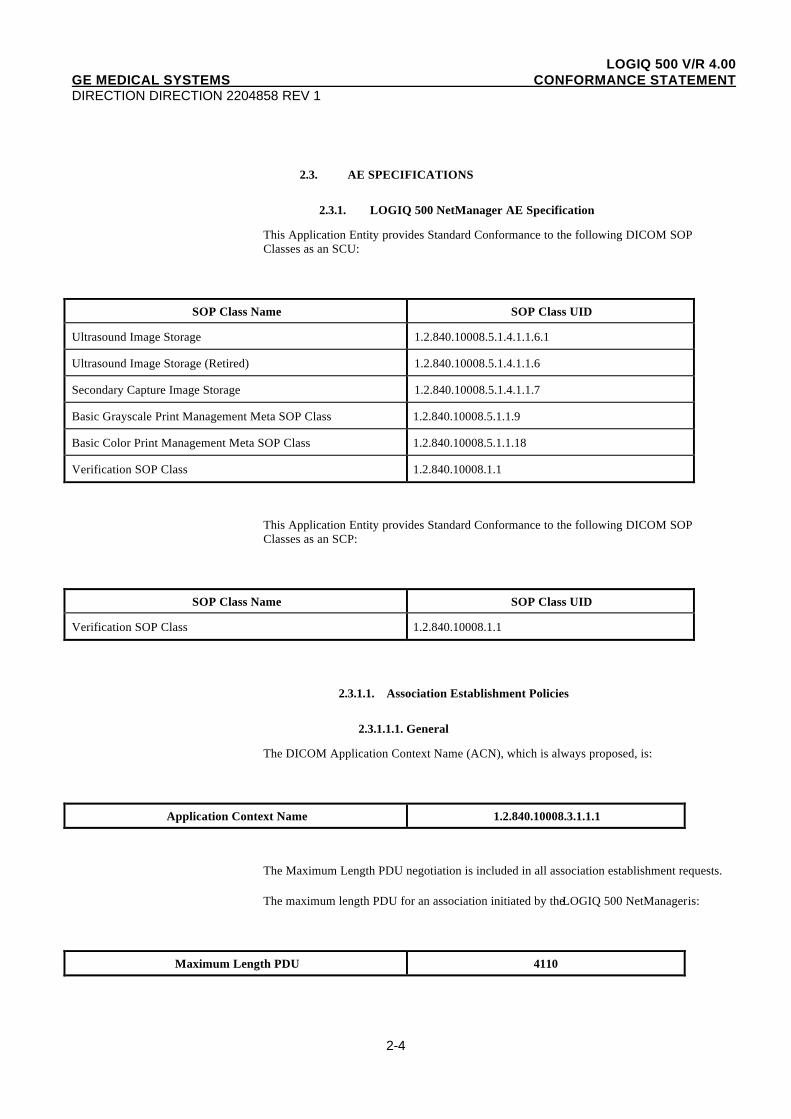
2.3. AE SPECIFICATIONS
2.3.1. LOGIQ 500 NetManager AE Specification
This Application Entity provides Standard Conformance to the following DICOM SOPClasses as an SCU:
SOP Class Name SOP Class UID
Ultrasound Image Storage 1.2.840.10008.5.1.4.1.1.6.1
Ultrasound Image Storage (Retired) 1.2.840.10008.5.1.4.1.1.6
Secondary Capture Image Storage 1.2.840.10008.5.1.4.1.1.7
Basic Grayscale Print Management Meta SOP Class 1.2.840.10008.5.1.1.9
Basic Color Print Management Meta SOP Class 1.2.840.10008.5.1.1.18
Verification SOP Class 1.2.840.10008.1.1
This Application Entity provides Standard Conformance to the following DICOM SOPClasses as an SCP:
SOP Class Name SOP Class UID
Verification SOP Class 1.2.840.10008.1.1
2.3.1.1. Association Establishment Policies
2.3.1.1.1. General
The DICOM Application Context Name (ACN), which is always proposed, is:
Application Context Name 1.2.840.10008.3.1.1.1
The Maximum Length PDU negotiation is included in all association establishment requests.
The maximum length PDU for an association initiated by the LOGIQ 500 NetManager is:
Maximum Length PDU 4110
LOGIQ 500 V/R 4.00GE MEDICAL SYSTEMS CONFORMANCE STATEMENTDIRECTION DIRECTION 2204858 REV 1
2-5
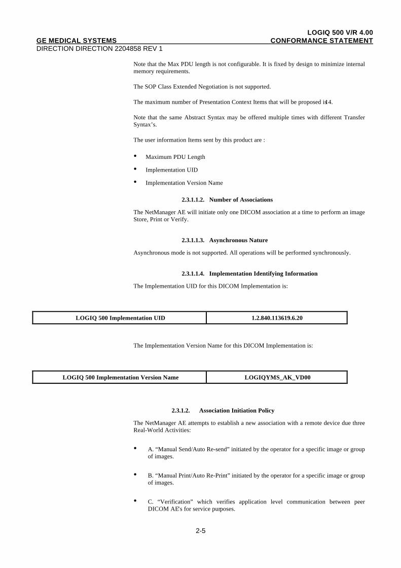
Note that the Max PDU length is not configurable. It is fixed by design to minimize internalmemory requirements.
The SOP Class Extended Negotiation is not supported.
The maximum number of Presentation Context Items that will be proposed is 14.
Note that the same Abstract Syntax may be offered multiple times with different TransferSyntax’s.
The user information Items sent by this product are :
• Maximum PDU Length
• Implementation UID
• Implementation Version Name
2.3.1.1.2. Number of Associations
The NetManager AE will initiate only one DICOM association at a time to perform an imageStore, Print or Verify.
2.3.1.1.3. Asynchronous Nature
Asynchronous mode is not supported. All operations will be performed synchronously.
2.3.1.1.4. Implementation Identifying Information
The Implementation UID for this DICOM Implementation is:
LOGIQ 500 Implementation UID 1.2.840.113619.6.20
The Implementation Version Name for this DICOM Implementation is:
LOGIQ 500 Implementation Version Name LOGIQYMS_AK_VD00
2.3.1.2. Association Initiation Policy
The NetManager AE attempts to establish a new association with a remote device due threeReal-World Activities:
• A. “Manual Send/Auto Re-send” initiated by the operator for a specific image or groupof images.
• B. “Manual Print/Auto Re-Print” initiated by the operator for a specific image or groupof images.
• C. “Verification” which verifies application level communication between peerDICOM AE’s for service purposes.
LOGIQ 500 V/R 4.00GE MEDICAL SYSTEMS CONFORMANCE STATEMENTDIRECTION DIRECTION 2204858 REV 1
2-6
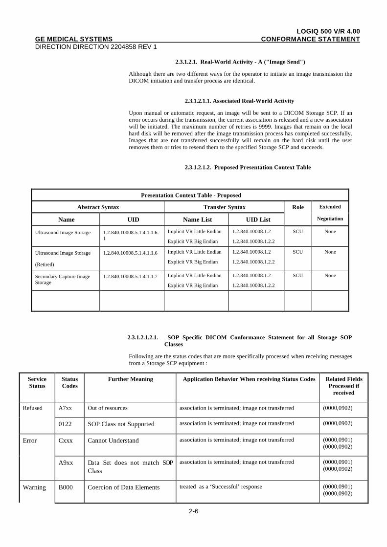
2.3.1.2.1. Real-World Activity - A ("Image Send")
Although there are two different ways for the operator to initiate an image transmission theDICOM initiation and transfer process are identical.
2.3.1.2.1.1. Associated Real-World Activity
Upon manual or automatic request, an image will be sent to a DICOM Storage SCP. If anerror occurs during the transmission, the current association is released and a new associationwill be initiated. The maximum number of retries is 9999. Images that remain on the localhard disk will be removed after the image transmission process has completed successfully.Images that are not transferred successfully will remain on the hard disk until the userremoves them or tries to resend them to the specified Storage SCP and succeeds.
2.3.1.2.1.2. Proposed Presentation Context Table
Presentation Context Table - Proposed
Abstract Syntax Transfer Syntax Role Extended
Name UID Name List UID List Negotiation
Ultrasound Image Storage 1.2.840.10008.5.1.4.1.1.6.1
Implicit VR Little Endian
Explicit VR Big Endian
1.2.840.10008.1.2
1.2.840.10008.1.2.2
SCU None
Ultrasound Image Storage
(Retired)
1.2.840.10008.5.1.4.1.1.6 Implicit VR Little Endian
Explicit VR Big Endian
1.2.840.10008.1.2
1.2.840.10008.1.2.2
SCU None
Secondary Capture ImageStorage
1.2.840.10008.5.1.4.1.1.7 Implicit VR Little Endian
Explicit VR Big Endian
1.2.840.10008.1.2
1.2.840.10008.1.2.2
SCU None
2.3.1.2.1.2.1. SOP Specific DICOM Conformance Statement for all Storage SOPClasses
Following are the status codes that are more specifically processed when receiving messagesfrom a Storage SCP equipment :
ServiceStatus
StatusCodes
Further Meaning Application Behavior When receiving Status Codes Related FieldsProcessed if
received
Refused A7xx Out of resources association is terminated; image not transferred (0000,0902)
0122 SOP Class not Supported association is terminated; image not transferred (0000,0902)
Error Cxxx Cannot Understand association is terminated; image not transferred (0000,0901)(0000,0902)
A9xx Data Set does not match SOPClass
association is terminated; image not transferred (0000,0901)(0000,0902)
Warning B000 Coercion of Data Elements treated as a ‘Successful’ response (0000,0901)(0000,0902)
LOGIQ 500 V/R 4.00GE MEDICAL SYSTEMS CONFORMANCE STATEMENTDIRECTION DIRECTION 2204858 REV 1
2-7
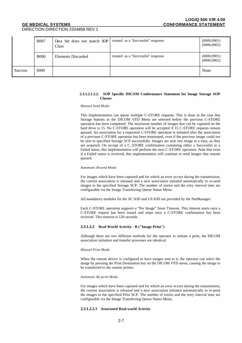
B007 Data Set does not match SOPClass
treated as a ‘Successful’ response (0000,0901)(0000,0902)
B006 Elements Discarded treated as a ‘Successful’ response (0000,0901)(0000,0902)
Success 0000 None
2.3.1.2.1.2.2. SOP Specific DICOM Conformance Statement for Image Storage SOPClasses
Manual Send Mode:
This Implementation can queue multiple C-STORE requests. This is done in the case thatStorage buttons in the DICOM VFD Menu are selected before the previous C-STOREoperation has been completed. The maximum number of images that can be captured on thehard drive is 15. No C-STORE operation will be accepted if 15 C-STORE requests remainqueued. An association for a requested C-STORE operation is initiated after the associationof a previous C-STORE operation has been terminated, even if the previous image could notbe sent to specified Storage SCP successfully. Images are sent one image at a time, as theyare acquired. On receipt of a C_STORE confirmation containing either a Successful or aFailed status, this implementation will perform the next C-STORE operation. Note that evenif a Failed status is received, this implementation will continue to send images that remainqueued.
Automatic Resend Mode:
For images which have been captured and for which an error occurs during the transmission,the current association is released and a new association initiated automatically to re-sendimages to the specified Storage SCP. The number of retries and the retry interval time areconfigurable via the Image Transferring Queue Status Menu.
All mandatory modules for the SC IOD and US IOD are provided by the NetManager.
Each C-STORE operation supports a “Per Image” Store Timeout. This timeout starts once aC-STORE request has been issued and stops once a C-STORE confirmation has beenrecieved. This timeout is 120 seconds.
2.3.1.2.2 Real-World Activity - B ("Image Print")
Although there are two different methods for the operator to initiate a print, the DICOMassociation initiation and transfer processes are identical.
Manual Print Mode:
When the remote device is configured to have images sent to it, the operator can select theimage by pressing the Print Destination key on the DICOM VFD menu, causing the image tobe transferred to the remote printer.
Automatic Re-print Mode:
For images which have been captured and for which an error occurs during the transmission,the current association is released and a new association initiated automatically to re-printthe images to the specified Print SCP. The number of retries and the retry interval time areconfigurable via the Image Transferring Queue Status Menu.
2.3.1.2.2.1 Associated Real-world Activity
LOGIQ 500 V/R 4.00GE MEDICAL SYSTEMS CONFORMANCE STATEMENTDIRECTION DIRECTION 2204858 REV 1
2-8
Upon a request by the operator (Manual Print/Automatic re-print), an image will be sent to aDICOM Print SCP. If an error occurs during the transmission, the current association isreleased and a new association initiated. The maximum number of retries is 15.
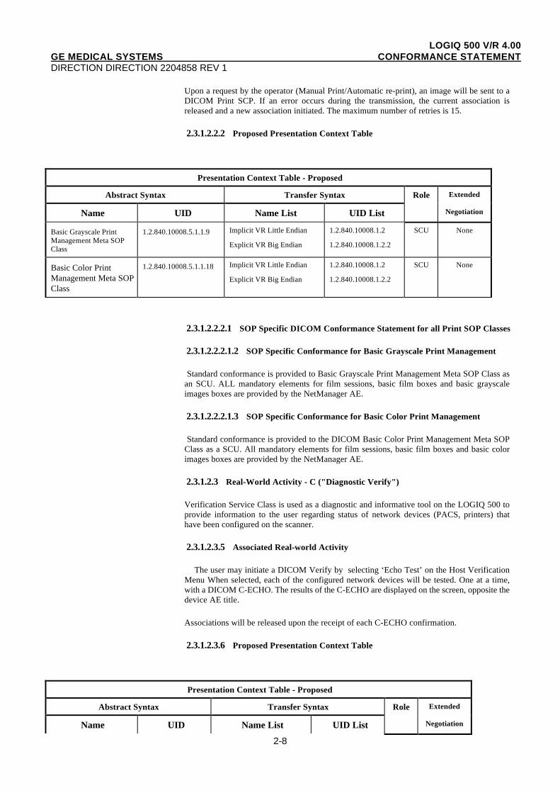
2.3.1.2.2.2 Proposed Presentation Context Table
Presentation Context Table - Proposed
Abstract Syntax Transfer Syntax Role Extended
Name UID Name List UID List Negotiation
Basic Grayscale PrintManagement Meta SOPClass
1.2.840.10008.5.1.1.9 Implicit VR Little Endian
Explicit VR Big Endian
1.2.840.10008.1.2
1.2.840.10008.1.2.2
SCU None
Basic Color PrintManagement Meta SOPClass
1.2.840.10008.5.1.1.18 Implicit VR Little Endian
Explicit VR Big Endian
1.2.840.10008.1.2
1.2.840.10008.1.2.2
SCU None
2.3.1.2.2.2.1 SOP Specific DICOM Conformance Statement for all Print SOP Classes
2.3.1.2.2.2.1.2 SOP Specific Conformance for Basic Grayscale Print Management
Standard conformance is provided to Basic Grayscale Print Management Meta SOP Class asan SCU. ALL mandatory elements for film sessions, basic film boxes and basic grayscaleimages boxes are provided by the NetManager AE.
2.3.1.2.2.2.1.3 SOP Specific Conformance for Basic Color Print Management
Standard conformance is provided to the DICOM Basic Color Print Management Meta SOPClass as a SCU. All mandatory elements for film sessions, basic film boxes and basic colorimages boxes are provided by the NetManager AE.
2.3.1.2.3 Real-World Activity - C ("Diagnostic Verify")
Verification Service Class is used as a diagnostic and informative tool on the LOGIQ 500 toprovide information to the user regarding status of network devices (PACS, printers) thathave been configured on the scanner.
2.3.1.2.3.5 Associated Real-world Activity
The user may initiate a DICOM Verify by selecting ‘Echo Test’ on the Host VerificationMenu When selected, each of the configured network devices will be tested. One at a time,with a DICOM C-ECHO. The results of the C-ECHO are displayed on the screen, opposite thedevice AE title.
Associations will be released upon the receipt of each C-ECHO confirmation.
2.3.1.2.3.6 Proposed Presentation Context Table
Presentation Context Table - Proposed
Abstract Syntax Transfer Syntax Role Extended
Name UID Name List UID List Negotiation
LOGIQ 500 V/R 4.00GE MEDICAL SYSTEMS CONFORMANCE STATEMENTDIRECTION DIRECTION 2204858 REV 1
2-9
Verification SOP Class 1.2.840.10008.1.1 Implicit VR Little Endian 1.2.840.10008.1.2 SCU None
2.3.1.2.3.2.1 SOP Specific DICOM Conformance Statement for Verify SOP Class
The NetManager AE provides standard conformance to the Verification SOP Class as anSCU.
2.3.1.3. Association Acceptance Policy
The NetManager AE accepts an association only when the LOGIQ 500 scanner receives aVerification request from another network device.
2.3.1.3.1. Real-World Activity - Verification Request
2.3.1.3.1.1. Associated Real-World Activity
An incoming Verification Request will cause the NetManager AE to accept the associationand respond with a verification response.
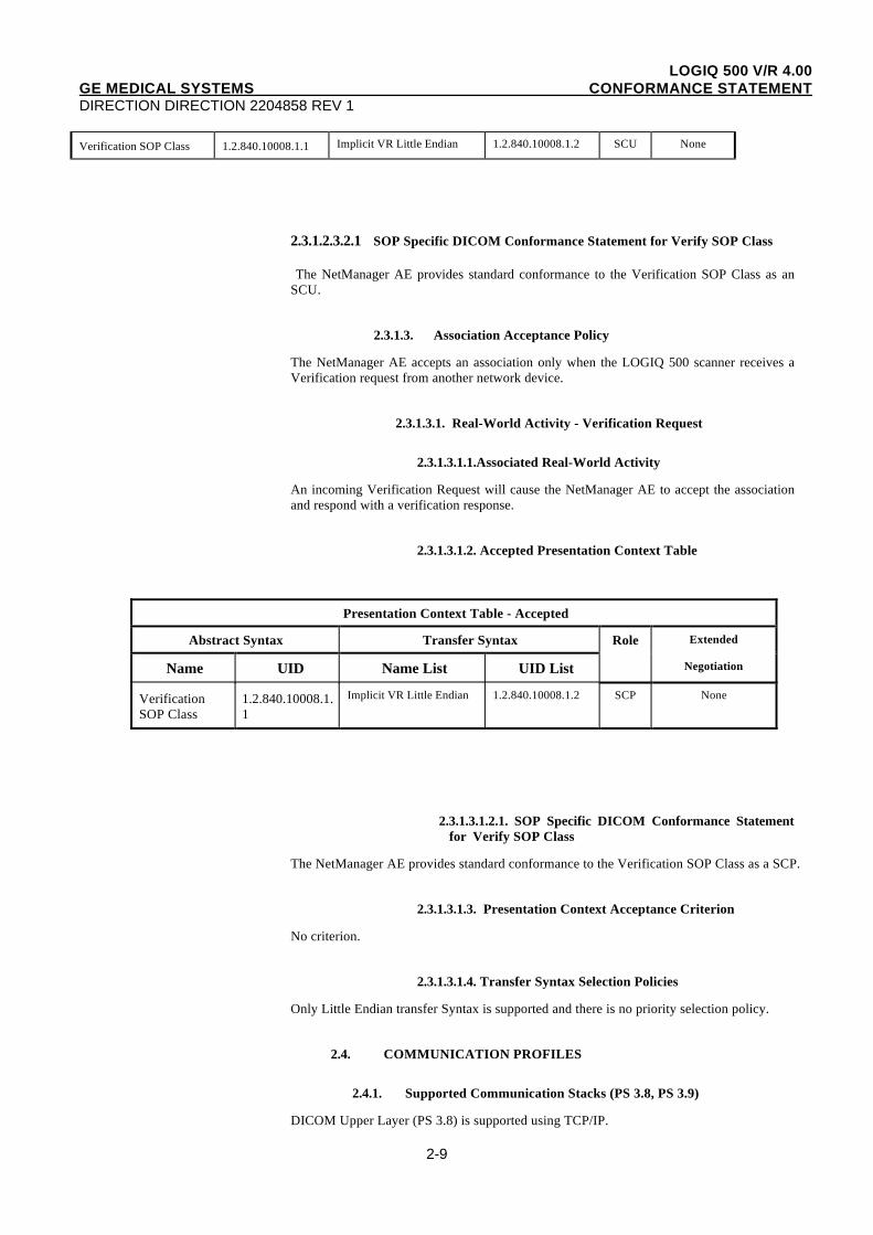
2.3.1.3.1.2. Accepted Presentation Context Table
Presentation Context Table - Accepted
Abstract Syntax Transfer Syntax Role Extended
Name UID Name List UID List Negotiation
VerificationSOP Class
1.2.840.10008.1.1
Implicit VR Little Endian 1.2.840.10008.1.2 SCP None
2.3.1.3.1.2.1. SOP Specific DICOM Conformance Statementfor Verify SOP Class
The NetManager AE provides standard conformance to the Verification SOP Class as a SCP.
2.3.1.3.1.3. Presentation Context Acceptance Criterion
No criterion.
2.3.1.3.1.4. Transfer Syntax Selection Policies
Only Little Endian transfer Syntax is supported and there is no priority selection policy.
2.4. COMMUNICATION PROFILES
2.4.1. Supported Communication Stacks (PS 3.8, PS 3.9)
DICOM Upper Layer (PS 3.8) is supported using TCP/IP.
LOGIQ 500 V/R 4.00GE MEDICAL SYSTEMS CONFORMANCE STATEMENTDIRECTION DIRECTION 2204858 REV 1
2-10
2.4.3. TCP/IP Stack
The TCP/IP stack is inherited from a pSOS/pNA Operating System which the LOGIQ 500application is built on.
2.4.3.1. API
Not applicable to this product.
2.4.3.2. Physical Media Support
Ethernet v2.0, IEEE 802.3.
2.5. EXTENSIONS / SPECIALIZATIONS / PRIVATIZATIONS
2.5.1. Standard Extended /Specialized/Private SOPs
Not applicable to this product.
2.6. CONFIGURATION
2.6.1. AE Title/Presentation Address Mapping
The Local AE title is configurable and is normally configured by a GEMS Service Engineerduring DICOM software installation. It can also be modified by the user if the need arises.The AE Title is a set from the Network Configuration Menu as part of the user interface.
2.6.2. Configurable Parameters
The following fields are configurable for this AE (local):
• Local AE Title
• Local IP Address
• Local Listening TCP/IP port number (port 104 is the default port number )
LOGIQ 500 V/R 4.00GE MEDICAL SYSTEMS CONFORMANCE STATEMENTDIRECTION DIRECTION 2204858 REV 1
2-11
• Local IP Netmask
• Local routing table information
The following fields are configurable for remote DICOM storage and print AE’s:
• Remote AE Title
• Remote IP Address
• Responding TCP/IP port number (only 4 digits’ port number is available)
• Remote host name
Note: All configurations must be performed by a GE Field Engineer.
2.7. SUPPORT OF EXTENDED CHARACTER SETS
ISO-IR 100 Latin alphabet No.1, supplementary font code set is supported.
LOGIQ 500 V/R 4.00GE MEDICAL SYSTEMS CONFORMANCE STATEMENTDIRECTION DIRECTION 2204858 REV 1
3-1
3. ULTRASOUND (US) INFORMATION OBJECT IMPLEMENTATION
3.1. INTRODUCTION
This section specifies the use of the DICOM US Image IOD to represent the information includedin US images produced by this implementation. Corresponding attributes are conveyed using themodule construct. The contents of this section are:
3.2 - IOD Description
3.3 - IOD Entity-Relationship Model
3.4 - IOD Module Table
3.5 - IOD Module Definition
3.2. US IOD IMPLEMENTATION
3.3. US ENTITY-RELATIONSHIP MODEL
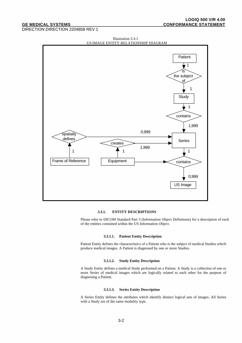
The Entity-Relationship diagram for the US Image interoperability schema is shown in Illustration3.3-1. In this figure, the following diagrammatic convention is established to represent theinformation organization :
• each entity is represented by a rectangular box
• each relationship is represented by a diamond shaped box.
• the fact that a relationship exists between two entities is depicted by lines connecting thecorresponding entity boxes to the relationship boxes.
The relationships are fully defined with the maximum number of possible entities in therelationship shown. In other words, the relationship between Series and Image can have up toImages 999 per Series, but the Patient to Study relationship has 1 Study for each Patient (a Patientcan have more than one Study on the system, however each Study will contain all of theinformation pertaining to that Patient).
LOGIQ 500 V/R 4.00GE MEDICAL SYSTEMS CONFORMANCE STATEMENTDIRECTION DIRECTION 2204858 REV 1
3-2
Illustration 3.3-1US IMAGE ENTITY RELATIONSHIP DIAGRAM
Patient
Study
isthe subject
of
contains
spatiallydefines
creates
Equipment
US Image
Frame of Reference contains
Series
0,999
1 1 11,999
0,9991,999
1
1
1
3.3.1. ENTITY DESCRIPTIONS
Please refer to DICOM Standard Part 3 (Information Object Definitions) for a description of eachof the entities contained within the US Information Object.
3.3.1.1. Patient Entity Description
Patient Entity defines the characteristics of a Patient who is the subject of medical Studies whichproduce medical images. A Patient is diagnosed by one or more Studies.
3.3.1.2. Study Entity Description
A Study Entity defines a medical Study performed on a Patient. A Study is a collection of one ormore Series of medical images which are logically related to each other for the purpose ofdiagnosing a Patient.
3.3.1.3. Series Entity Description
A Series Entity defines the attributes which identify distinct logical sets of images. All Serieswith a Study are of the same modality type.
LOGIQ 500 V/R 4.00GE MEDICAL SYSTEMS CONFORMANCE STATEMENTDIRECTION DIRECTION 2204858 REV 1
3-3
3.3.1.4. Equipment Entity Description
The Equipment Entity describes the imaging hardware which produced a particular Series ofimages.
3.3.1.5. Frame of Reference Entity Description
The Frame of Reference Entity uniquely identifies the spatial coordinate system which has beenused to produce an Image. An Image is related to one, and only one, Frame of Reference.
3.3.1.6. US Image Entity Description
The Image Entity defines the attributes which fully describe the pixel data of an Ultrasoundimage. The pixel data which was either generated as a direct result of Ultrasound scanning orderived from the pixel data of other US images (DEFF files stored on MODs).
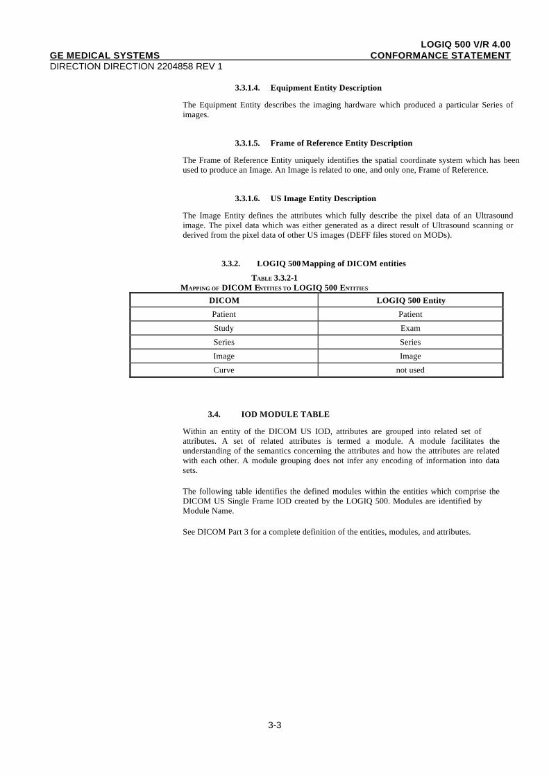
3.3.2. LOGIQ 500 Mapping of DICOM entities
TABLE 3.3.2-1MAPPING OF DICOM ENTITIES TO LOGIQ 500 ENTITIES
DICOM LOGIQ 500 Entity
Patient Patient
Study Exam
Series Series
Image Image
Curve not used
3.4. IOD MODULE TABLE
Within an entity of the DICOM US IOD, attributes are grouped into related set ofattributes. A set of related attributes is termed a module. A module facilitates theunderstanding of the semantics concerning the attributes and how the attributes are relatedwith each other. A module grouping does not infer any encoding of information into datasets.
The following table identifies the defined modules within the entities which comprise theDICOM US Single Frame IOD created by the LOGIQ 500. Modules are identified byModule Name.
See DICOM Part 3 for a complete definition of the entities, modules, and attributes.
LOGIQ 500 V/R 4.00GE MEDICAL SYSTEMS CONFORMANCE STATEMENTDIRECTION DIRECTION 2204858 REV 1
3-4
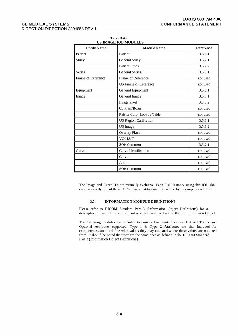
TABLE 3.4-1 US IMAGE IOD MODULES
Entity Name Module Name Reference
Patient Patient 3.5.1.1
Study General Study 3.5.2.1
Patient Study 3.5.2.2
Series General Series 3.5.3.1
Frame of Reference Frame of Reference not used
US Frame of Reference not used
Equipment General Equipment 3.5.5.1
Image General Image 3.5.6.1
Image Pixel 3.5.6.2
Contrast/Bolus not used
Palette Color Lookup Table not used
US Region Calibration 3.5.8.1
US Image 3.5.8.2
Overlay Plane not used
VOI LUT not used
SOP Common 3.5.7.1
Curve Curve Identification not used
Curve not used
Audio not used
SOP Common not used
The Image and Curve IEs are mutually exclusive. Each SOP Instance using this IOD shallcontain exactly one of these IODs. Curve entities are not created by this implementation.
3.5. INFORMATION MODULE DEFINITIONS
Please refer to DICOM Standard Part 3 (Information Object Definitions) for adescription of each of the entities and modules contained within the US Information Object.
The following modules are included to convey Enumerated Values, Defined Terms, andOptional Attributes supported. Type 1 & Type 2 Attributes are also included forcompleteness and to define what values they may take and where these values are obtainedfrom. It should be noted that they are the same ones as defined in the DICOM StandardPart 3 (Information Object Definitions).
LOGIQ 500 V/R 4.00GE MEDICAL SYSTEMS CONFORMANCE STATEMENTDIRECTION DIRECTION 2204858 REV 1
3-5
3.5.1. Common Patient Entity Modules
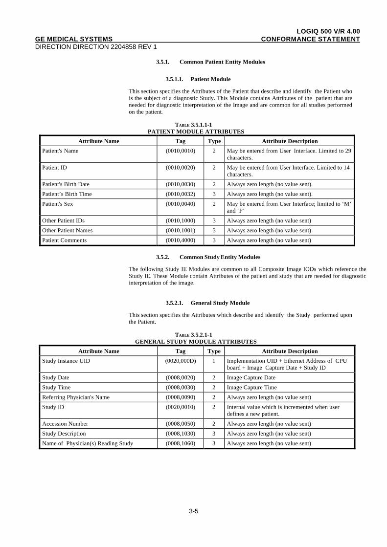
3.5.1.1. Patient Module
This section specifies the Attributes of the Patient that describe and identify the Patient whois the subject of a diagnostic Study. This Module contains Attributes of the patient that areneeded for diagnostic interpretation of the Image and are common for all studies performedon the patient.
TABLE 3.5.1.1-1 PATIENT MODULE ATTRIBUTES
Attribute Name Tag Type Attribute Description
Patient's Name (0010,0010) 2 May be entered from User Interface. Limited to 29characters.
Patient ID (0010,0020) 2 May be entered from User Interface. Limited to 14characters.
Patient's Birth Date (0010,0030) 2 Always zero length (no value sent).
Patient’s Birth Time (0010,0032) 3 Always zero length (no value sent).
Patient's Sex (0010,0040) 2 May be entered from User Interface; limited to ‘M’and ‘F’
Other Patient IDs (0010,1000) 3 Always zero length (no value sent)
Other Patient Names (0010,1001) 3 Always zero length (no value sent)
Patient Comments (0010,4000) 3 Always zero length (no value sent)
3.5.2. Common Study Entity Modules
The following Study IE Modules are common to all Composite Image IODs which reference theStudy IE. These Module contain Attributes of the patient and study that are needed for diagnosticinterpretation of the image.
3.5.2.1. General Study Module
This section specifies the Attributes which describe and identify the Study performed uponthe Patient.
TABLE 3.5.2.1-1GENERAL STUDY MODULE ATTRIBUTES
Attribute Name Tag Type Attribute Description
Study Instance UID (0020,000D) 1 Implementation UID + Ethernet Address of CPUboard + Image Capture Date + Study ID
Study Date (0008,0020) 2 Image Capture Date
Study Time (0008,0030) 2 Image Capture Time
Referring Physician's Name (0008,0090) 2 Always zero length (no value sent)
Study ID (0020,0010) 2 Internal value which is incremented when userdefines a new patient.
Accession Number (0008,0050) 2 Always zero length (no value sent)
Study Description (0008,1030) 3 Always zero length (no value sent)
Name of Physician(s) Reading Study (0008,1060) 3 Always zero length (no value sent)

LOGIQ 500 V/R 4.00GE MEDICAL SYSTEMS CONFORMANCE STATEMENTDIRECTION DIRECTION 2204858 REV 1
3-6
3.5.2.2. Patient Study Module
This section defines Attributes that provide information about the Patient at the time the Study wasperformed.
TABLE 3.5.2.2-1PATIENT STUDY MODULE ATTRIBUTES
Attribute Name Tag Type Attribute Description
Patient's Age (0010,1010) 3 May be entered from User Interface
Patient's Size (0010,1020) 3 May be entered from User Interface
Patient's Weight (0010,1030) 3 May be entered from User Interface
Additional Patient’s History (0010,21B0) 3 Always zero length (no value sent)
LOGIQ 500 V/R 4.00GE MEDICAL SYSTEMS CONFORMANCE STATEMENTDIRECTION DIRECTION 2204858 REV 1
3-7
3.5.3. Common Series Entity Modules
The following Series IE Modules are common to all Composite Image IODs which reference theSeries IE.
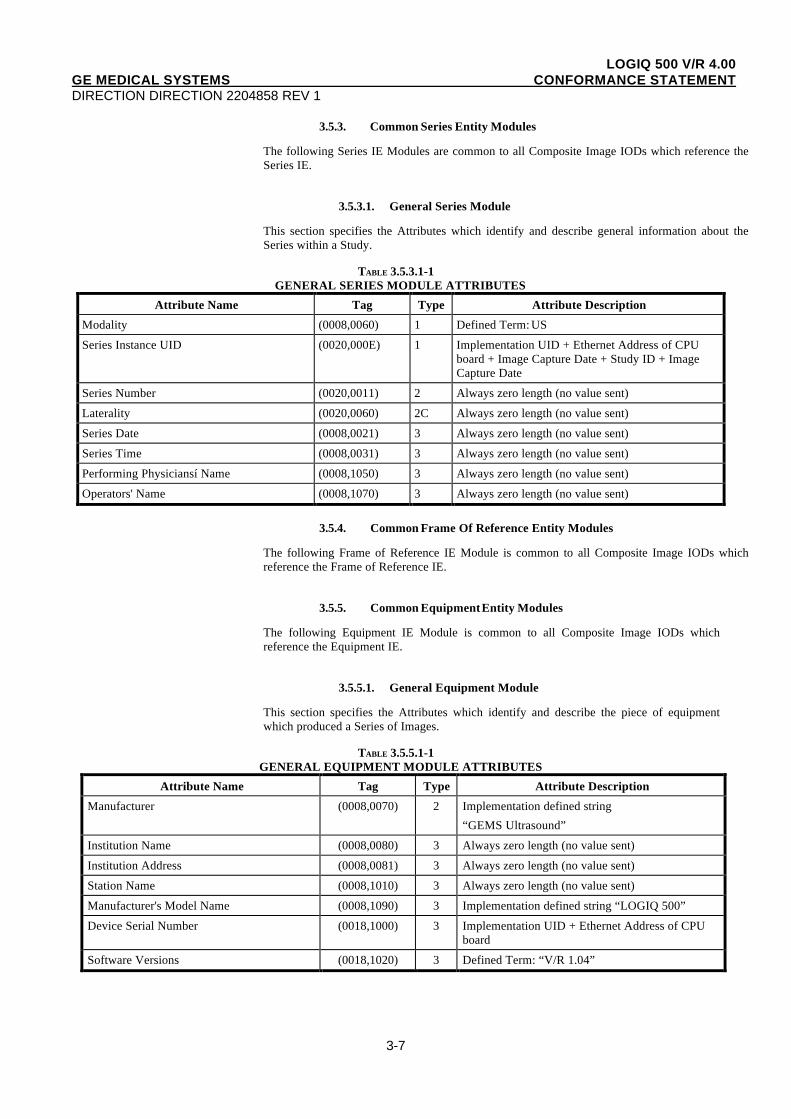
3.5.3.1. General Series Module
This section specifies the Attributes which identify and describe general information about theSeries within a Study.
TABLE 3.5.3.1-1GENERAL SERIES MODULE ATTRIBUTES
Attribute Name Tag Type Attribute Description
Modality (0008,0060) 1 Defined Term: US
Series Instance UID (0020,000E) 1 Implementation UID + Ethernet Address of CPUboard + Image Capture Date + Study ID + ImageCapture Date
Series Number (0020,0011) 2 Always zero length (no value sent)
Laterality (0020,0060) 2C Always zero length (no value sent)
Series Date (0008,0021) 3 Always zero length (no value sent)
Series Time (0008,0031) 3 Always zero length (no value sent)
Performing Physiciansí Name (0008,1050) 3 Always zero length (no value sent)
Operators' Name (0008,1070) 3 Always zero length (no value sent)
3.5.4. Common Frame Of Reference Entity Modules
The following Frame of Reference IE Module is common to all Composite Image IODs whichreference the Frame of Reference IE.
3.5.5. Common Equipment Entity Modules
The following Equipment IE Module is common to all Composite Image IODs whichreference the Equipment IE.
3.5.5.1. General Equipment Module
This section specifies the Attributes which identify and describe the piece of equipmentwhich produced a Series of Images.
TABLE 3.5.5.1-1GENERAL EQUIPMENT MODULE ATTRIBUTES
Attribute Name Tag Type Attribute Description
Manufacturer (0008,0070) 2 Implementation defined string
“GEMS Ultrasound”
Institution Name (0008,0080) 3 Always zero length (no value sent)
Institution Address (0008,0081) 3 Always zero length (no value sent)
Station Name (0008,1010) 3 Always zero length (no value sent)
Manufacturer's Model Name (0008,1090) 3 Implementation defined string “LOGIQ 500”
Device Serial Number (0018,1000) 3 Implementation UID + Ethernet Address of CPUboard
Software Versions (0018,1020) 3 Defined Term: “V/R 1.04”
LOGIQ 500 V/R 4.00GE MEDICAL SYSTEMS CONFORMANCE STATEMENTDIRECTION DIRECTION 2204858 REV 1
3-8
3.5.6. Common Image Entity Modules
The following Image IE Modules are common to all Composite Image IODs which referencethe Image IE.
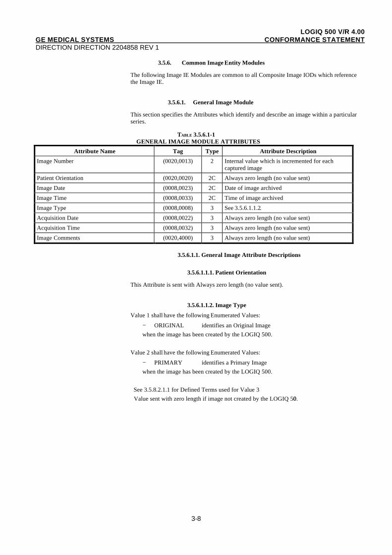
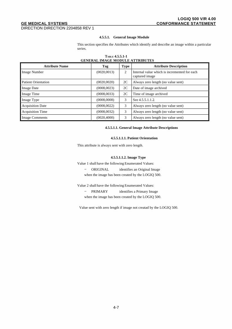
3.5.6.1. General Image Module
This section specifies the Attributes which identify and describe an image within a particularseries.
TABLE 3.5.6.1-1GENERAL IMAGE MODULE ATTRIBUTES
Attribute Name Tag Type Attribute Description
Image Number (0020,0013) 2 Internal value which is incremented for eachcaptured image
Patient Orientation (0020,0020) 2C Always zero length (no value sent)
Image Date (0008,0023) 2C Date of image archived
Image Time (0008,0033) 2C Time of image archived
Image Type (0008,0008) 3 See 3.5.6.1.1.2.
Acquisition Date (0008,0022) 3 Always zero length (no value sent)
Acquisition Time (0008,0032) 3 Always zero length (no value sent)
Image Comments (0020,4000) 3 Always zero length (no value sent)
3.5.6.1.1. General Image Attribute Descriptions
3.5.6.1.1.1. Patient Orientation
This Attribute is sent with Always zero length (no value sent).
3.5.6.1.1.2. Image Type
Value 1 shall have the following Enumerated Values:
− ORIGINAL identifies an Original Imagewhen the image has been created by the LOGIQ 500.
Value 2 shall have the following Enumerated Values:
− PRIMARY identifies a Primary Imagewhen the image has been created by the LOGIQ 500.
See 3.5.8.2.1.1 for Defined Terms used for Value 3Value sent with zero length if image not created by the LOGIQ 500.
LOGIQ 500 V/R 4.00GE MEDICAL SYSTEMS CONFORMANCE STATEMENTDIRECTION DIRECTION 2204858 REV 1
3-9
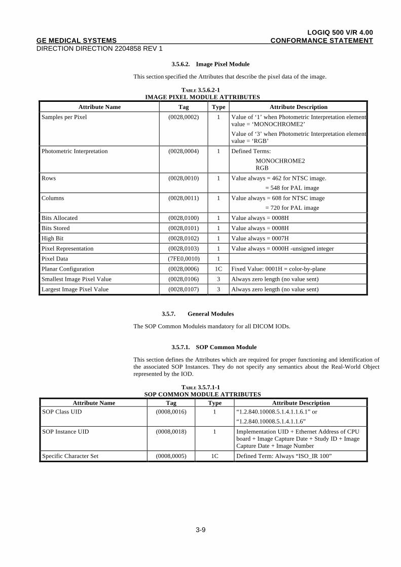
3.5.6.2. Image Pixel Module
This section specified the Attributes that describe the pixel data of the image.
TABLE 3.5.6.2-1IMAGE PIXEL MODULE ATTRIBUTES
Attribute Name Tag Type Attribute Description
Samples per Pixel (0028,0002) 1 Value of ‘1’ when Photometric Interpretation elementvalue = ‘MONOCHROME2’
Value of ‘3’ when Photometric Interpretation elementvalue = ‘RGB’
Photometric Interpretation (0028,0004) 1 Defined Terms:
MONOCHROME2RGB
Rows (0028,0010) 1 Value always = 462 for NTSC image.
= 548 for PAL image
Columns (0028,0011) 1 Value always = 608 for NTSC image
= 720 for PAL image
Bits Allocated (0028,0100) 1 Value always = 0008H
Bits Stored (0028,0101) 1 Value always = 0008H
High Bit (0028,0102) 1 Value always = 0007H
Pixel Representation (0028,0103) 1 Value always = 0000H -unsigned integer
Pixel Data (7FE0,0010) 1
Planar Configuration (0028,0006) 1C Fixed Value: 0001H = color-by-plane
Smallest Image Pixel Value (0028,0106) 3 Always zero length (no value sent)
Largest Image Pixel Value (0028,0107) 3 Always zero length (no value sent)
3.5.7. General Modules
The SOP Common Module is mandatory for all DICOM IODs.
3.5.7.1. SOP Common Module
This section defines the Attributes which are required for proper functioning and identification ofthe associated SOP Instances. They do not specify any semantics about the Real-World Objectrepresented by the IOD.
TABLE 3.5.7.1-1SOP COMMON MODULE ATTRIBUTES
Attribute Name Tag Type Attribute DescriptionSOP Class UID (0008,0016) 1 “1.2.840.10008.5.1.4.1.1.6.1” or
“1.2.840.10008.5.1.4.1.1.6”
SOP Instance UID (0008,0018) 1 Implementation UID + Ethernet Address of CPUboard + Image Capture Date + Study ID + ImageCapture Date + Image Number
Specific Character Set (0008,0005) 1C Defined Term: Always “ISO_IR 100”
LOGIQ 500 V/R 4.00GE MEDICAL SYSTEMS CONFORMANCE STATEMENTDIRECTION DIRECTION 2204858 REV 1
3-10
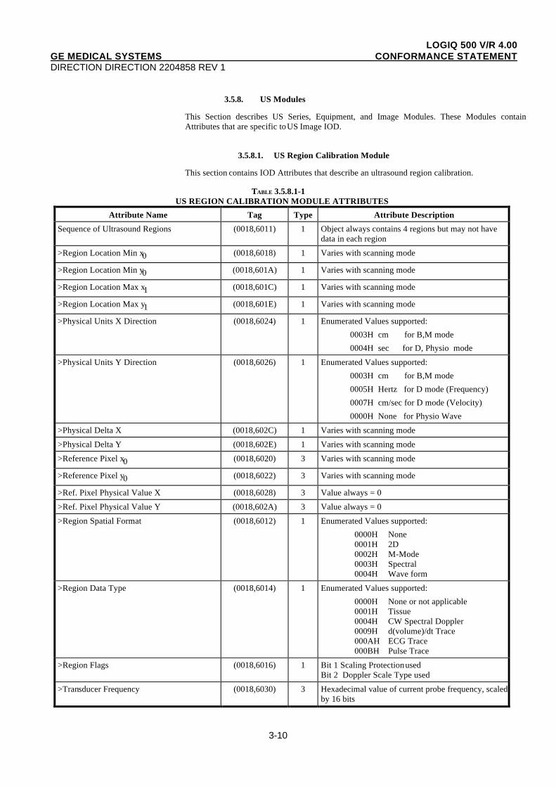
3.5.8. US Modules
This Section describes US Series, Equipment, and Image Modules. These Modules containAttributes that are specific to US Image IOD.
3.5.8.1. US Region Calibration Module
This section contains IOD Attributes that describe an ultrasound region calibration.
TABLE 3.5.8.1-1US REGION CALIBRATION MODULE ATTRIBUTES
Attribute Name Tag Type Attribute Description
Sequence of Ultrasound Regions (0018,6011) 1 Object always contains 4 regions but may not havedata in each region
>Region Location Min x0 (0018,6018) 1 Varies with scanning mode
>Region Location Min y0 (0018,601A) 1 Varies with scanning mode
>Region Location Max x1 (0018,601C) 1 Varies with scanning mode
>Region Location Max y1 (0018,601E) 1 Varies with scanning mode
>Physical Units X Direction (0018,6024) 1 Enumerated Values supported:
0003H cm for B,M mode
0004H sec for D, Physio mode
>Physical Units Y Direction (0018,6026) 1 Enumerated Values supported:
0003H cm for B,M mode
0005H Hertz for D mode (Frequency)
0007H cm/sec for D mode (Velocity)
0000H None for Physio Wave
>Physical Delta X (0018,602C) 1 Varies with scanning mode
>Physical Delta Y (0018,602E) 1 Varies with scanning mode
>Reference Pixel x0 (0018,6020) 3 Varies with scanning mode
>Reference Pixel y0 (0018,6022) 3 Varies with scanning mode
>Ref. Pixel Physical Value X (0018,6028) 3 Value always = 0
>Ref. Pixel Physical Value Y (0018,602A) 3 Value always = 0
>Region Spatial Format (0018,6012) 1 Enumerated Values supported:
0000H None0001H 2D0002H M-Mode0003H Spectral0004H Wave form
>Region Data Type (0018,6014) 1 Enumerated Values supported:
0000H None or not applicable0001H Tissue0004H CW Spectral Doppler0009H d(volume)/dt Trace000AH ECG Trace000BH Pulse Trace
>Region Flags (0018,6016) 1 Bit 1 Scaling Protection usedBit 2 Doppler Scale Type used
>Transducer Frequency (0018,6030) 3 Hexadecimal value of current probe frequency, scaledby 16 bits
LOGIQ 500 V/R 4.00GE MEDICAL SYSTEMS CONFORMANCE STATEMENTDIRECTION DIRECTION 2204858 REV 1
3-11
>Pulse Repetition Frequency (0018,6032) 3 Hexadecimal value of current probe PRF, scaled by16 bits
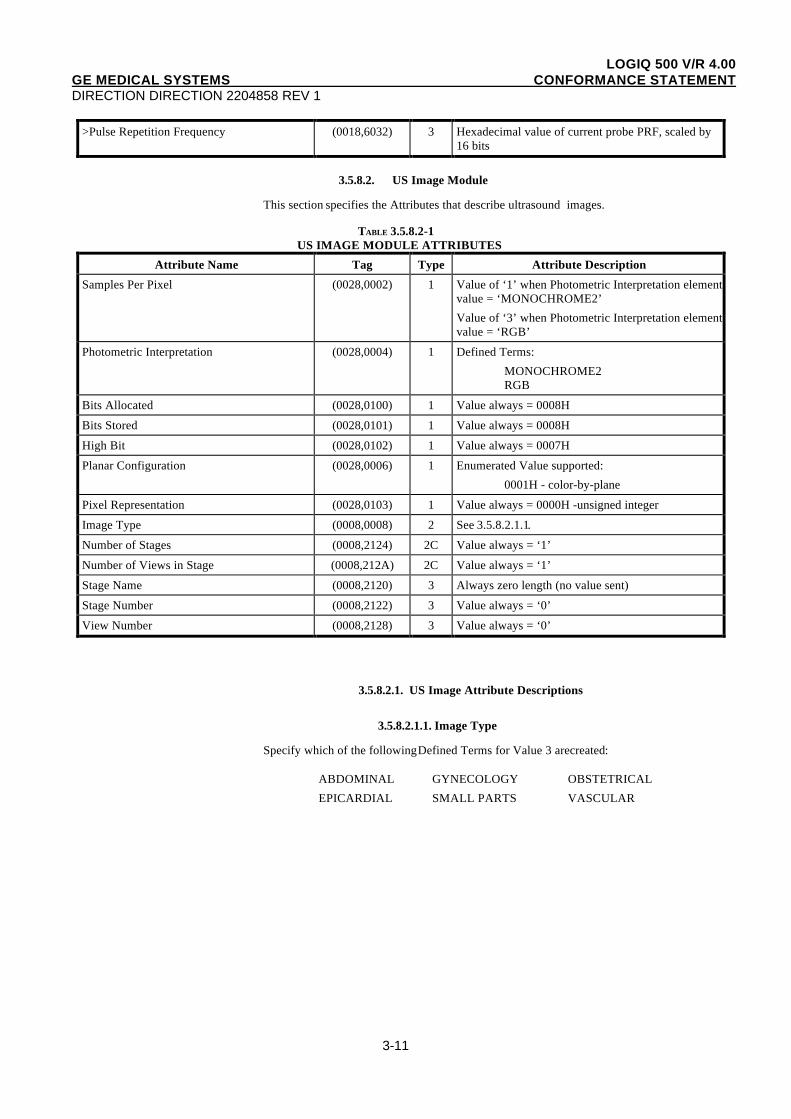
3.5.8.2. US Image Module
This section specifies the Attributes that describe ultrasound images.
TABLE 3.5.8.2-1US IMAGE MODULE ATTRIBUTES
Attribute Name Tag Type Attribute Description
Samples Per Pixel (0028,0002) 1 Value of ‘1’ when Photometric Interpretation elementvalue = ‘MONOCHROME2’
Value of ‘3’ when Photometric Interpretation elementvalue = ‘RGB’
Photometric Interpretation (0028,0004) 1 Defined Terms:
MONOCHROME2RGB
Bits Allocated (0028,0100) 1 Value always = 0008H
Bits Stored (0028,0101) 1 Value always = 0008H
High Bit (0028,0102) 1 Value always = 0007H
Planar Configuration (0028,0006) 1 Enumerated Value supported:
0001H - color-by-plane
Pixel Representation (0028,0103) 1 Value always = 0000H -unsigned integer
Image Type (0008,0008) 2 See 3.5.8.2.1.1.
Number of Stages (0008,2124) 2C Value always = ‘1’
Number of Views in Stage (0008,212A) 2C Value always = ‘1’
Stage Name (0008,2120) 3 Always zero length (no value sent)
Stage Number (0008,2122) 3 Value always = ‘0’
View Number (0008,2128) 3 Value always = ‘0’
3.5.8.2.1. US Image Attribute Descriptions
3.5.8.2.1.1. Image Type
Specify which of the following Defined Terms for Value 3 are created:
ABDOMINAL GYNECOLOGY OBSTETRICAL
EPICARDIAL SMALL PARTS VASCULAR
LOGIQ 500 V/R 4.00GE MEDICAL SYSTEMS CONFORMANCE STATEMENTDIRECTION DIRECTION 2204858 REV 1
4-1
4. SC INFORMATION OBJECT IMPLEMENTATION
4.1. INTRODUCTION
This section specifies the use of the DICOM SC Image IOD to represent the informationincluded in SC images produced by this implementation. Corresponding attributes areconveyed using the module construct. The contents of this section are:
4.2 - IOD Description
4.3 - IOD Entity-Relationship Model
4.4 - IOD Module Table
4.5 - IOD Module Definition
4.2. SC IOD IMPLEMENTATION
4.3. SC ENTITY-RELATIONSHIP MODEL
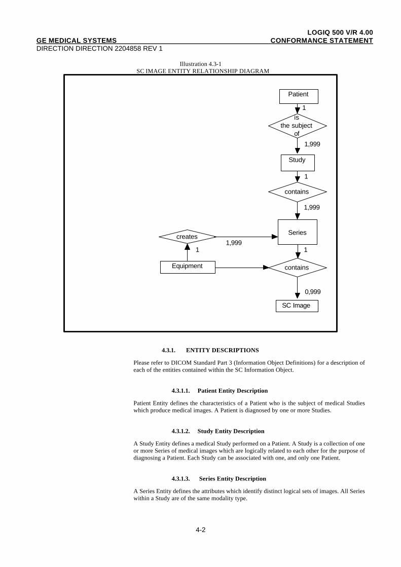
The Entity-Relationship diagram for the SC Image interoperability schema is shown inIllustration 4.3-1. In this figure, the following diagrammatic convention is established torepresent the information organization :
• each entity is represented by a rectangular box
• each relationship is represented by a diamond shaped box.
• the fact that a relationship exists between two entities is depicted by lines connecting thecorresponding entity boxes to the relationship boxes.
The relationships are fully defined with the maximum number of possible entities in therelationship shown. In other words, the relationship between Series and Image can have up to999 Images per Series, but the Patient to Study relationship has 1 Study for each Patient (aPatient can have more than one Study on the system, however each Study will contain all ofthe information pertaining to that Patient).
LOGIQ 500 V/R 4.00GE MEDICAL SYSTEMS CONFORMANCE STATEMENTDIRECTION DIRECTION 2204858 REV 1
4-2
Illustration 4.3-1SC IMAGE ENTITY RELATIONSHIP DIAGRAM
Patient
Study
isthe subject
of
contains
creates
Equipment
SC Image
contains
Series
0,999
1 11,999
1,999
1
1,999
1
4.3.1. ENTITY DESCRIPTIONS
Please refer to DICOM Standard Part 3 (Information Object Definitions) for a description ofeach of the entities contained within the SC Information Object.
4.3.1.1. Patient Entity Description
Patient Entity defines the characteristics of a Patient who is the subject of medical Studieswhich produce medical images. A Patient is diagnosed by one or more Studies.
4.3.1.2. Study Entity Description
A Study Entity defines a medical Study performed on a Patient. A Study is a collection of oneor more Series of medical images which are logically related to each other for the purpose ofdiagnosing a Patient. Each Study can be associated with one, and only one Patient.
4.3.1.3. Series Entity Description
A Series Entity defines the attributes which identify distinct logical sets of images. All Serieswithin a Study are of the same modality type.

LOGIQ 500 V/R 4.00GE MEDICAL SYSTEMS CONFORMANCE STATEMENTDIRECTION DIRECTION 2204858 REV 1
4-3
4.3.1.4. Equipment Entity Description
The Equipment Entity describes the imaging hardware which produced a particular Series ofimages. A Single piece of Equipment may produce one or more Series within a Study.
4.3.1.5. SC Image Entity Description
4.3.1.6. Overlay Entity Description
4.3.1.7. VOI Lookup Table Entity Description
4.3.2. LOGIQ 500 Mapping of DICOM entities
TABLE 4.3.2-1MAPPING OF DICOM ENTITIES TO LOGIQ 500 ENTITIES
DICOM LOGIQ 500 Entity
Patient Patient
Study Exam
Series Series
Image Image
Frame Not Applicable
4.4. IOD MODULE TABLE
Within an entity of the DICOM SC IOD, attributes are grouped into related set ofattributes. A set of related attributes is termed a module. A module facilitates theunderstanding of the semantics concerning the attributes and how the attributes are relatedwith each other. A module grouping does not infer any encoding of information into datasets.
Table 4.4-1 identifies the defined modules within the entities which comprise the DICOMSC IOD. Modules are identified by Module Name.
See DICOM Part 3 for a complete definition of the entities, modules, and attributes.
TABLE 4.4-1 SC IMAGE IOD MODULES
Entity Name Module Name Reference
Patient Patient 4.5.1.1
Study General Study 4.5.2.1
Patient Study Not used
Series General Series 4.5.3.1
Equipment General Equipment 4.5.4.1
SC Equipment 4.5.7.1
Image General Image 4.5.5.1
Image Pixel 4.5.5.2
SC Image 4.5.7.2
Overlay Plane Not used
Modality LUT Not used
VOI LUT Not used
SOP Common 4.5.6.1
LOGIQ 500 V/R 4.00GE MEDICAL SYSTEMS CONFORMANCE STATEMENTDIRECTION DIRECTION 2204858 REV 1
4-4
4.5. INFORMATION MODULE DEFINITIONS
Please refer to DICOM Standard Part 3 (Information Object Definitions) for adescription of each of the entities and modules contained within the SC Information Object.
The following modules are included to convey Enumerated Values, Defined Terms, andOptional Attributes supported. Type 1 & Type 2 Attributes are also included forcompleteness and to define what values they may take and where these values are obtainedfrom. It should be noted that they are the same ones as defined in the DICOM StandardPart 3 (Information Object Definitions).
4.5.1. Common Patient Entity Modules
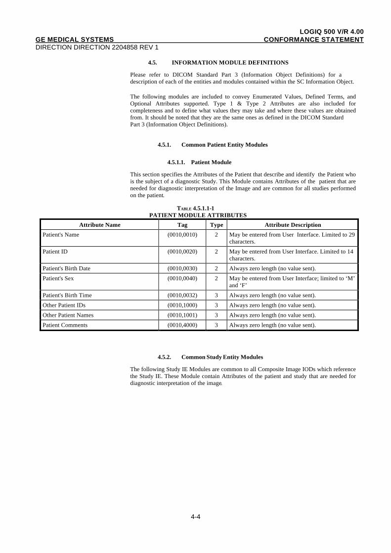
4.5.1.1. Patient Module
This section specifies the Attributes of the Patient that describe and identify the Patient whois the subject of a diagnostic Study. This Module contains Attributes of the patient that areneeded for diagnostic interpretation of the Image and are common for all studies performedon the patient.
TABLE 4.5.1.1-1 PATIENT MODULE ATTRIBUTES
Attribute Name Tag Type Attribute Description
Patient's Name (0010,0010) 2 May be entered from User Interface. Limited to 29characters.
Patient ID (0010,0020) 2 May be entered from User Interface. Limited to 14characters.
Patient's Birth Date (0010,0030) 2 Always zero length (no value sent).
Patient's Sex (0010,0040) 2 May be entered from User Interface; limited to ‘M’and ‘F’
Patient's Birth Time (0010,0032) 3 Always zero length (no value sent).
Other Patient IDs (0010,1000) 3 Always zero length (no value sent).
Other Patient Names (0010,1001) 3 Always zero length (no value sent).
Patient Comments (0010,4000) 3 Always zero length (no value sent).
4.5.2. Common Study Entity Modules
The following Study IE Modules are common to all Composite Image IODs which referencethe Study IE. These Module contain Attributes of the patient and study that are needed fordiagnostic interpretation of the image.
LOGIQ 500 V/R 4.00GE MEDICAL SYSTEMS CONFORMANCE STATEMENTDIRECTION DIRECTION 2204858 REV 1
4-5
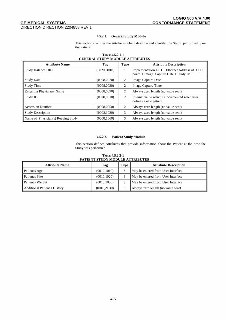
4.5.2.1. General Study Module
This section specifies the Attributes which describe and identify the Study performed uponthe Patient.
TABLE 4.5.2.1-1GENERAL STUDY MODULE ATTRIBUTES
Attribute Name Tag Type Attribute Description
Study Instance UID (0020,000D) 1 Implementation UID + Ethernet Address of CPUboard + Image Capture Date + Study ID
Study Date (0008,0020) 2 Image Capture Date
Study Time (0008,0030) 2 Image Capture Time
Referring Physician's Name (0008,0090) 2 Always zero length (no value sent)
Study ID (0020,0010) 2 Internal value which is incremented when userdefines a new patient.
Accession Number (0008,0050) 2 Always zero length (no value sent)
Study Description (0008,1030) 3 Always zero length (no value sent)
Name of Physician(s) Reading Study (0008,1060) 3 Always zero length (no value sent)
4.5.2.2. Patient Study Module
This section defines Attributes that provide information about the Patient at the time theStudy was performed.
TABLE 4.5.2.2-1PATIENT STUDY MODULE ATTRIBUTES
Attribute Name Tag Type Attribute Description
Patient's Age (0010,1010) 3 May be entered from User Interface
Patient's Size (0010,1020) 3 May be entered from User Interface
Patient's Weight (0010,1030) 3 May be entered from User Interface
Additional Patient’s History (0010,21B0) 3 Always zero length (no value sent)
LOGIQ 500 V/R 4.00GE MEDICAL SYSTEMS CONFORMANCE STATEMENTDIRECTION DIRECTION 2204858 REV 1
4-6
4.5.3. Common Series Entity Modules
The following Series IE Modules are common to all Composite Image IODs which referencethe Series IE.
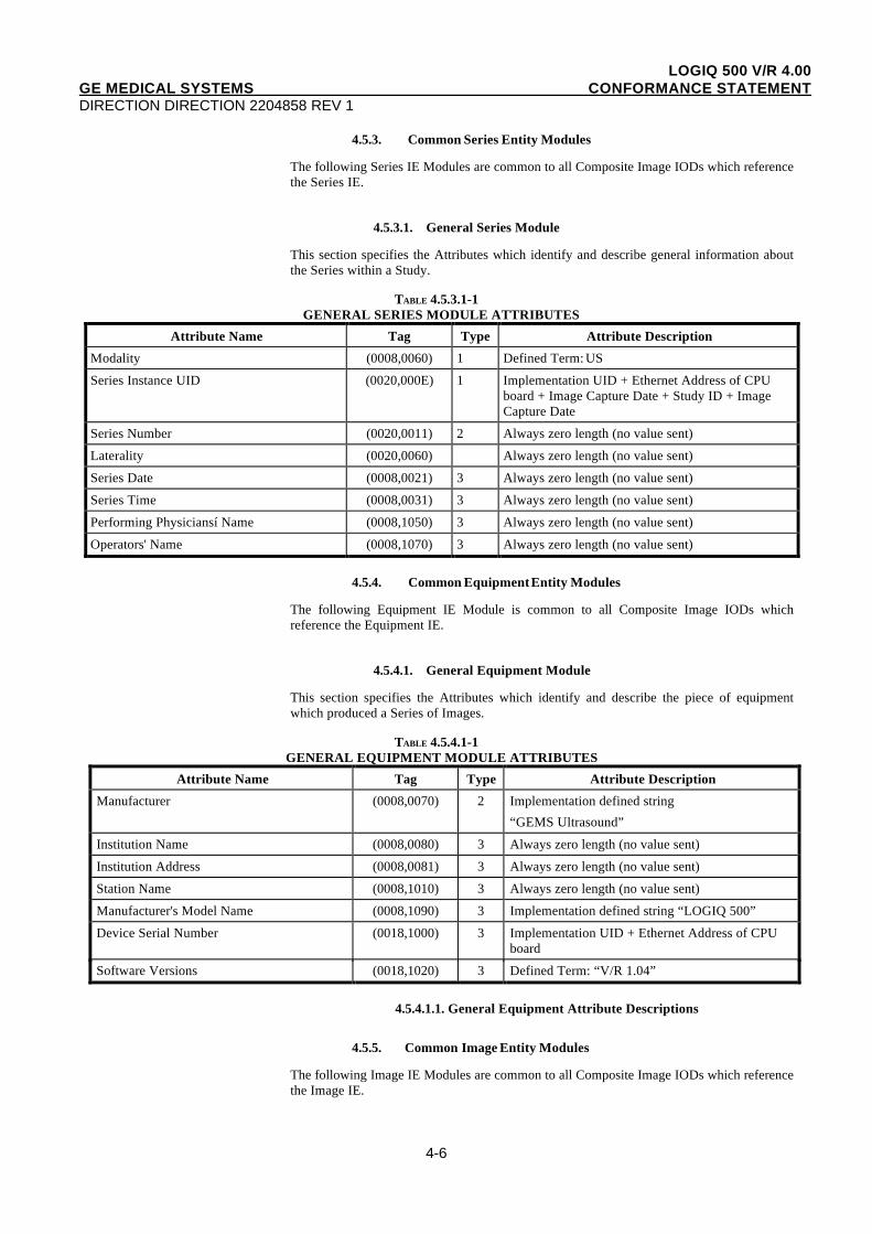
4.5.3.1. General Series Module
This section specifies the Attributes which identify and describe general information aboutthe Series within a Study.
TABLE 4.5.3.1-1GENERAL SERIES MODULE ATTRIBUTES
Attribute Name Tag Type Attribute Description
Modality (0008,0060) 1 Defined Term: US
Series Instance UID (0020,000E) 1 Implementation UID + Ethernet Address of CPUboard + Image Capture Date + Study ID + ImageCapture Date
Series Number (0020,0011) 2 Always zero length (no value sent)
Laterality (0020,0060) Always zero length (no value sent)
Series Date (0008,0021) 3 Always zero length (no value sent)
Series Time (0008,0031) 3 Always zero length (no value sent)
Performing Physiciansí Name (0008,1050) 3 Always zero length (no value sent)
Operators' Name (0008,1070) 3 Always zero length (no value sent)
4.5.4. Common Equipment Entity Modules
The following Equipment IE Module is common to all Composite Image IODs whichreference the Equipment IE.
4.5.4.1. General Equipment Module
This section specifies the Attributes which identify and describe the piece of equipmentwhich produced a Series of Images.
TABLE 4.5.4.1-1GENERAL EQUIPMENT MODULE ATTRIBUTES
Attribute Name Tag Type Attribute Description
Manufacturer (0008,0070) 2 Implementation defined string
“GEMS Ultrasound”
Institution Name (0008,0080) 3 Always zero length (no value sent)
Institution Address (0008,0081) 3 Always zero length (no value sent)
Station Name (0008,1010) 3 Always zero length (no value sent)
Manufacturer's Model Name (0008,1090) 3 Implementation defined string “LOGIQ 500”
Device Serial Number (0018,1000) 3 Implementation UID + Ethernet Address of CPUboard
Software Versions (0018,1020) 3 Defined Term: “V/R 1.04”
4.5.4.1.1. General Equipment Attribute Descriptions
4.5.5. Common Image Entity Modules
The following Image IE Modules are common to all Composite Image IODs which referencethe Image IE.
LOGIQ 500 V/R 4.00GE MEDICAL SYSTEMS CONFORMANCE STATEMENTDIRECTION DIRECTION 2204858 REV 1
4-7
4.5.5.1. General Image Module
This section specifies the Attributes which identify and describe an image within a particularseries.
TABLE 4.5.5.1-1GENERAL IMAGE MODULE ATTRIBUTES
Attribute Name Tag Type Attribute Description
Image Number (0020,0013) 2 Internal value which is incremented for eachcaptured image
Patient Orientation (0020,0020) 2C Always zero length (no value sent)
Image Date (0008,0023) 2C Date of image archived
Image Time (0008,0033) 2C Time of image archived
Image Type (0008,0008) 3 See 4.5.5.1.1.2.
Acquisition Date (0008,0022) 3 Always zero length (no value sent)
Acquisition Time (0008,0032) 3 Always zero length (no value sent)
Image Comments (0020,4000) 3 Always zero length (no value sent)
4.5.5.1.1. General Image Attribute Descriptions
4.5.5.1.1.1. Patient Orientation
This attribute is always sent with zero length.
4.5.5.1.1.2. Image Type
Value 1 shall have the following Enumerated Values:
− ORIGINAL identifies an Original Imagewhen the image has been created by the LOGIQ 500.
Value 2 shall have the following Enumerated Values:
− PRIMARY identifies a Primary Imagewhen the image has been created by the LOGIQ 500.
Value sent with zero length if image not creatad by the LOGIQ 500.
LOGIQ 500 V/R 4.00GE MEDICAL SYSTEMS CONFORMANCE STATEMENTDIRECTION DIRECTION 2204858 REV 1
4-8
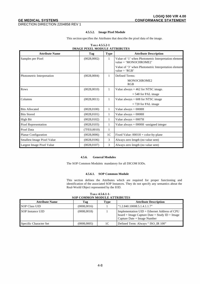
4.5.5.2. Image Pixel Module
This section specifies the Attributes that describe the pixel data of the image.
TABLE 4.5.5.2-1IMAGE PIXEL MODULE ATTRIBUTES
Attribute Name Tag Type Attribute Description
Samples per Pixel (0028,0002) 1 Value of ‘1’ when Photometric Interpretation elementvalue = ‘MONOCHROME2’
Value of ‘3’ when Photometric Interpretation elementvalue = ‘RGB’
Photometric Interpretation (0028,0004) 1 Defined Terms:
MONOCHROME2RGB
Rows (0028,0010) 1 Value always = 462 for NTSC image.
= 548 for PAL image
Columns (0028,0011) 1 Value always = 608 for NTSC image
= 720 for PAL image
Bits Allocated (0028,0100) 1 Value always = 0008H
Bits Stored (0028,0101) 1 Value always = 0008H
High Bit (0028,0102) 1 Value always = 0007H
Pixel Representation (0028,0103) 1 Value always = 0000H -unsigned integer
Pixel Data (7FE0,0010) 1
Planar Configuration (0028,0006) 1C Fixed Value: 0001H = color-by-plane
Smallest Image Pixel Value (0028,0106) 3 Always zero length (no value sent)
Largest Image Pixel Value (0028,0107) 3 Always zero length (no value sent)
4.5.6. General Modules
The SOP Common Module is mandatory for all DICOM IODs.
4.5.6.1. SOP Common Module
This section defines the Attributes which are required for proper functioning andidentification of the associated SOP Instances. They do not specify any semantics about theReal-World Object represented by the IOD.
TABLE 4.5.6.1-1-SOP COMMON MODULE ATTRIBUTES
Attribute Name Tag Type Attribute DescriptionSOP Class UID (0008,0016) 1 “1.2.840.10008.5.1.4.1.1.7”
SOP Instance UID (0008,0018) 1 Implementation UID + Ethernet Address of CPUboard + Image Capture Date + Study ID + ImageCapture Date + Image Number
Specific Character Set (0008,0005) 1C Defined Term: Always “ ISO_IR 100”
LOGIQ 500 V/R 4.00GE MEDICAL SYSTEMS CONFORMANCE STATEMENTDIRECTION DIRECTION 2204858 REV 1
4-9
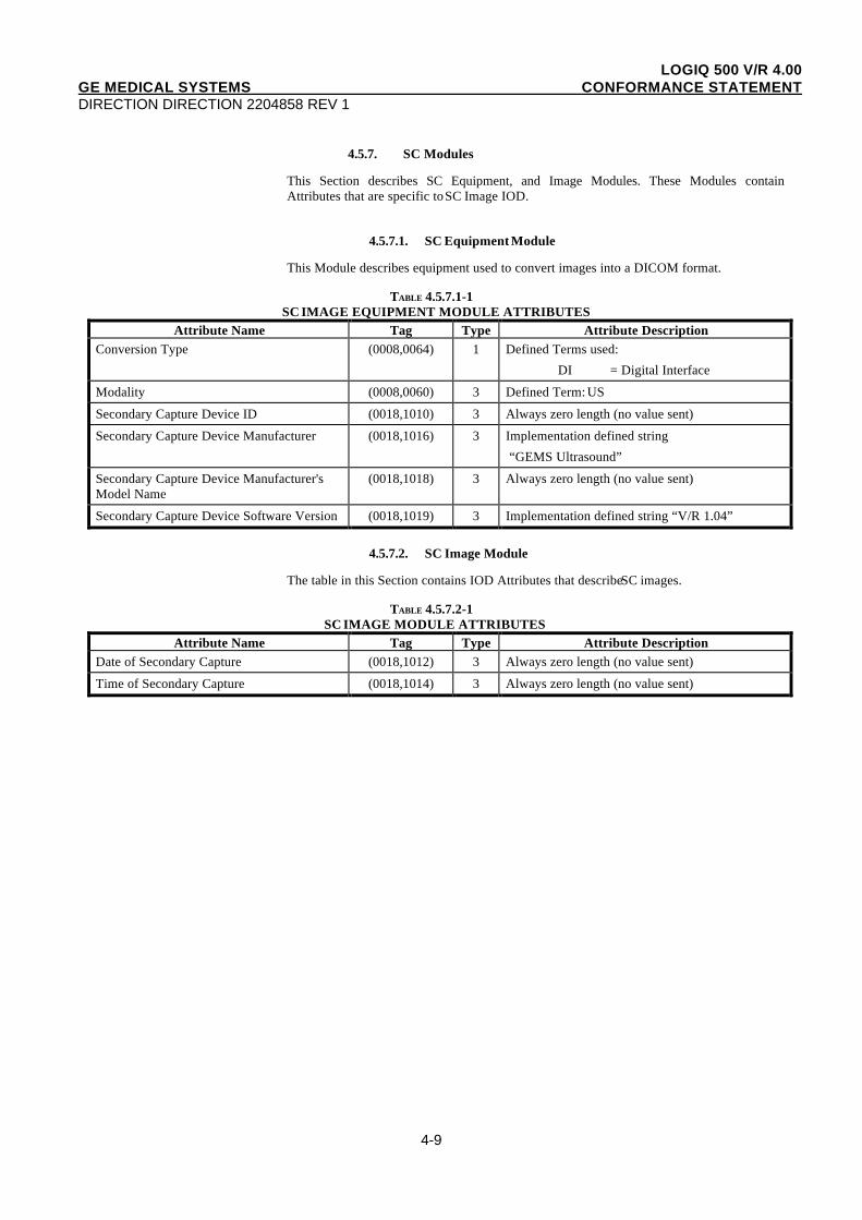
4.5.7. SC Modules
This Section describes SC Equipment, and Image Modules. These Modules containAttributes that are specific to SC Image IOD.
4.5.7.1. SC Equipment Module
This Module describes equipment used to convert images into a DICOM format.
TABLE 4.5.7.1-1SC IMAGE EQUIPMENT MODULE ATTRIBUTES
Attribute Name Tag Type Attribute DescriptionConversion Type (0008,0064) 1 Defined Terms used:
DI = Digital Interface
Modality (0008,0060) 3 Defined Term: US
Secondary Capture Device ID (0018,1010) 3 Always zero length (no value sent)
Secondary Capture Device Manufacturer (0018,1016) 3 Implementation defined string
“GEMS Ultrasound”
Secondary Capture Device Manufacturer'sModel Name
(0018,1018) 3 Always zero length (no value sent)
Secondary Capture Device Software Version (0018,1019) 3 Implementation defined string “V/R 1.04”
4.5.7.2. SC Image Module
The table in this Section contains IOD Attributes that describe SC images.
TABLE 4.5.7.2-1SC IMAGE MODULE ATTRIBUTES
Attribute Name Tag Type Attribute DescriptionDate of Secondary Capture (0018,1012) 3 Always zero length (no value sent)
Time of Secondary Capture (0018,1014) 3 Always zero length (no value sent)

LOGIQ 500 V/R 4.00GE MEDICAL SYSTEMS CONFORMANCE STATEMENTDIRECTION DIRECTION 2204858 REV 1
5-1
5. PRINT MANAGEMENT SOP CLASS DEFINITION
5.1. INTRODUCTION
This section of the DICOM Conformance Statement specifies the supported PrintManagement SOP and Meta SOP Classes, the optional attributes and service elementssupported, the valid range of values for mandatory and optional attributes, and the status codebehavior.
This section contains:
5.2 Basic Print Management Meta SOP Classes
5.3 Print Management SOP Class Definitions
5.4 Print Management IODs
5.5 IOD Module Definition
5.2. BASIC PRINT MANAGEMENT META SOP CLASSES
The Basic Print Management Meta SOP Classes correspond with the minimum functionalitythat an implementation of the Print Management Service Class shall support.
The LOGIQ 500 supports the Basic Grayscale Print Management Meta SOP Class and theBasic Color Print Management Meta SOP Class. These are defined in Table 5.2.1-1 andTable 5.2.2-1
5.2.1. Basic Grayscale Print Management Meta SOP Class
The Basic Grayscale Print Management Meta SOP Class is defined by the following set ofsupported SOP Classes.
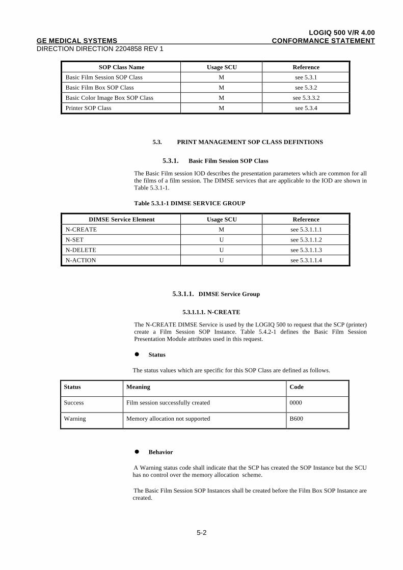
TABLE 5.2.1-1 BASIC GRAYSCALE PRINT MANAGEMENT META SOP CLASS
SOP Class Name Usage SCU Reference
Basic Film Session SOP Class M see 5.3.1
Basic Film Box SOP Class M see 5.3.2
Basic Grayscale Image Box SOP Class M see 5.3.3.1
Printer SOP Class M see 5.3.4
5.2.2. Basic Color Print Management Meta SOP Class
The Basic Color Print Management Meta SOP Class is defined by the following set ofsupported SOP Classes.
TABLE 5.2.2-1 BASIC COLOR PRINT MANAGEMENT META SOP CLASS
LOGIQ 500 V/R 4.00GE MEDICAL SYSTEMS CONFORMANCE STATEMENTDIRECTION DIRECTION 2204858 REV 1
5-2
SOP Class Name Usage SCU Reference
Basic Film Session SOP Class M see 5.3.1
Basic Film Box SOP Class M see 5.3.2
Basic Color Image Box SOP Class M see 5.3.3.2
Printer SOP Class M see 5.3.4
5.3. PRINT MANAGEMENT SOP CLASS DEFINTIONS
5.3.1. Basic Film Session SOP Class
The Basic Film session IOD describes the presentation parameters which are common for allthe films of a film session. The DIMSE services that are applicable to the IOD are shown inTable 5.3.1-1.
Table 5.3.1-1 DIMSE SERVICE GROUP
DIMSE Service Element Usage SCU Reference
N-CREATE M see 5.3.1.1.1
N-SET U see 5.3.1.1.2
N-DELETE U see 5.3.1.1.3
N-ACTION U see 5.3.1.1.4
5.3.1.1. DIMSE Service Group
5.3.1.1.1. N-CREATE
The N-CREATE DIMSE Service is used by the LOGIQ 500 to request that the SCP (printer)create a Film Session SOP Instance. Table 5.4.2-1 defines the Basic Film SessionPresentation Module attributes used in this request.
Status
The status values which are specific for this SOP Class are defined as follows.
Status Meaning Code
Success Film session successfully created 0000
Warning Memory allocation not supported B600
Behavior
A Warning status code shall indicate that the SCP has created the SOP Instance but the SCUhas no control over the memory allocation scheme.
The Basic Film Session SOP Instances shall be created before the Film Box SOP Instance arecreated.
LOGIQ 500 V/R 4.00GE MEDICAL SYSTEMS CONFORMANCE STATEMENTDIRECTION DIRECTION 2204858 REV 1
5-3
At any time the SCU shall only support one Basic Film Session SOP Instance on anAssociation.
5.3.1.1.2. N-SET
Not used in this implementation.
5.3.1.1.3. N-DELETE
The N-DELETE DIMSE Service is used by the LOGIQ 500 to request the SCP (printer) todelete the complete Film Session SOP Hierarchy. The root Film Session SOP Instance UID issent to the SCP to accomplish this.
Status
There are no specific status codes.
Behavior
The SCU uses the N-DELETE to request the SCP to delete the Basic Film Session SOPInstance Hierarchy.
5.3.1.1.4. N-ACTION
Not used in this implementation.
5.3.2. Basic Film Box SOP Class
The Basic Film Box IOD is an abstraction of the presentation of one film of the film session.The DIMSE services that are applicable to the IOD are shown in Table 5.3.2-1.
Table 5.3.2-1 DIMSE SERVICE GROUP
DIMSE Service Element Usage SCU Reference
N-CREATE M see 5.3.2.1.1
N-ACTION M see 5.3.2.1.2
N-DELETE U see 5.3.2.1.3
N-SET U see 5.3.2.1.4
5.3.2.1. DIMSE Service Group
5.3.2.1.1. N-CREATE
The N-CREATE DIMSE Service is used by the LOGIQ 500 to request that the SCP create aFilm Box SOP Instance. Table 5.4.2-1 defines the Basic Film Box Presentation Moduleattributes used in this request.
Status
There are no specific status codes.
Behavior
The SCU uses the N-CREATE to request the SCP to create a Basic Film Box SOP Instance.
LOGIQ 500 V/R 4.00GE MEDICAL SYSTEMS CONFORMANCE STATEMENTDIRECTION DIRECTION 2204858 REV 1
5-4
5.3.2.1.2. N-ACTION
The N-ACTION DIMSE Service is used by the LOGIQ 500 to request the SCP (printer) toprint one copy of a single film of the film session.
Status
Status Meaning Code
Success Film accepted for printing; if supported, the Print Job SOP Instanceis created.
0000
Warning Film Box SOP Instance hierarchy does not contain image Box SOPInstances (empty page).
B603
Failure Unable to create Print Job SOP Instance;print queue is full. C602
Image position collision: multiple images assigned to singleposition.
C604
Image size is larger than image box size (by using the specifiedmagnification value).
C603
Behavior
The SCU uses the N-ACTION to request the SCP to print one copy of a single film of thefilm session.
5.3.2.1.3. N-DELETE
Not used in this implementation.
5.3.2.1.4. N-SET
Not used in this implementation.
5.3.3. Image Box SOP Class
5.3.3.1. Basic Grayscale Image Box SOP Class
The Basic Grayscale Image Box IOD is an abstraction of the presentation of an image andimage related data in the image area of a film. The DIMSE services that are applicable to theIOD are shown in Table 5.3.3-1.
Table 5.3.3-1 DIMSE SERVICE GROUP
DIMSE Service Element Usage SCU Reference
N-SET M see 5.3.3.1.1
5.3.3.1.1. N-SET
The N-SET DIMSE Service is used by the LOGIQ 500 to update the Basic Grayscale ImageBox SOP Instance. Table 5.5.2.-5 defines the Basic Image Box Presentation Moduleattributes used.
LOGIQ 500 V/R 4.00GE MEDICAL SYSTEMS CONFORMANCE STATEMENTDIRECTION DIRECTION 2204858 REV 1
5-5
Status
The status values which are specific for the SOP Class are defined as follows.
Staus Meaning Code
Failure Insufficient memory in printer to store the image C605
Behavior
The SCU uses the N-SET to request the SCP to update a Basic Grayscale Image Box SOPInstance. The SCU shall only specify the SOP Instance UID of a Basic Grayscale Image BoxBelonging to the last created Film Box SOP Instance and shall specify the list of Attributesfor which the Attribute Values are to be set.
5.3.3.2. Basic Color Image Box SOP Class
The Basic Color Image Box IOD is an abstraction of the presentation of an image and imagerelated data in the image area of a film. The DIMSE services that are applicable to the IODare shown in Table 5.3.3-2.
Table 5.3.3-2 DIMSE SERVICE GROUP
DIMSE Service Element Usage SCU Reference
N-SET M see 5.3.3.2.1
5.3.3.2.1. N-SET
The N-SET DIMSE service is used by the LOGIQ 500 to update the Basic Color Image BoxSOP Instance. Table 5.5.2-5 defines the Basic Image Box Presentation Module attributesused.
Status
The status values which are specific for this SOP Class are defined as follows.
Status Meaning Code
Failure Insufficient memory in printer to store the image C605
Behavior
The SCU uses the N-SET to request the SCP to update a Basic Color image Box SOPInstance. The SCU shall only specify the SOP Instance UID of a Basic Color Image Boxbelonging to the last created Film Box SOP Instance and shall specify the list of Attributes forwhich the Attribute Values are to be set.
LOGIQ 500 V/R 4.00GE MEDICAL SYSTEMS CONFORMANCE STATEMENTDIRECTION DIRECTION 2204858 REV 1
5-6
5.3.4. Printer SOP Class
The Printer IOD is an abstraction of the hard copy printer and is the basic Information Entityto monitor the status of the printer. The DIMSE services that are applicable to the IOD areshown in Table 5.3.4-1.
5.3.4.1. DIMSE Service Group
Table 5.3.4-1 DIMSE SERVICE GROUP
DIMSE Service Element Usage SCU Reference
N-EVENT-REPORT M see 5.3.4.1.1
N-GET U see 5.3.4.1.2
5.3.4.1.1. N-EVENT_REPORT
The LOGIQ 500 confirms the N-EVENT-REPORT initiated by the SCP (printer)
Behavior
The SCU shall return the confirmation from the N-EVENT-REPORT operation.
5.3.4.1.2. N-GET
Used by the LOGIQ 500 to request the SCP to get a Printer SOP Instance. Table 5.5.2-6defines the Printer Module attributes.
5.4. PRINT MANAGEMENT IODS
Within an entity of a DICOM Print Management, attributes are grouped into a relatedset of attributes. A set of related attributes is termed a module. A module facilitates theunderstanding of the semantics concerning the attributes and how the attributes are relatedwith each other. A module grouping does not infer any encoding of information into datasets.
Table 5.4.1-1, Table 5.4.2-1, Table 5.4.3-1, and Table 5.4.4-1 identify the defined moduleswithin the entities which comprise the DICOM Print Management Service IODs.Modules are identified by Module Name.
See DICOM for a complete definition of the entities, modules and attributes.
5.4.1. Film Session IOD Module
TABLE 5.4.1-1 FILM SESSION IOD MODULE
Module Name Reference
SOP Common Module 5.5.1.1
Basic Film Session Presentation Module 5.5.2.1
Basic Film Session Relationship Module 5.5.2.2
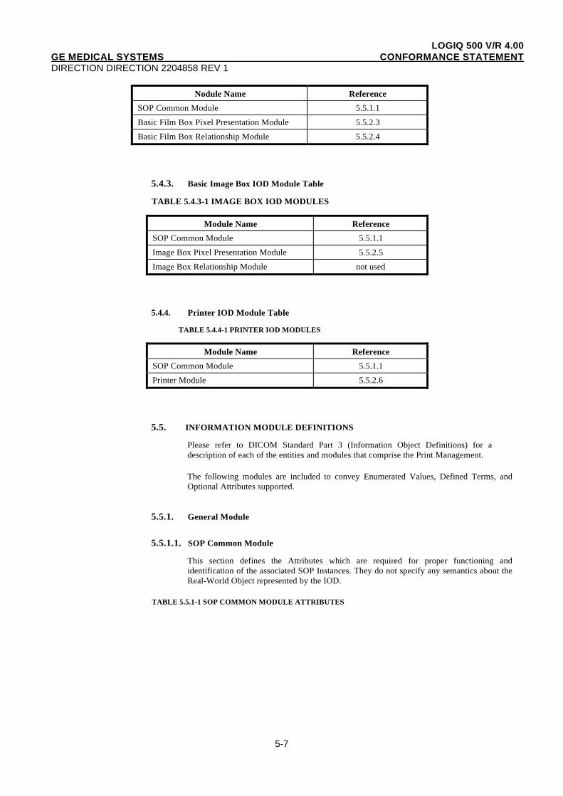
5.4.2. Basic Film Box IOD Module Table
TABLE 5.4.2-1 BASIC FILM BOX IOD MODULES
LOGIQ 500 V/R 4.00GE MEDICAL SYSTEMS CONFORMANCE STATEMENTDIRECTION DIRECTION 2204858 REV 1
5-7
Nodule Name Reference
SOP Common Module 5.5.1.1
Basic Film Box Pixel Presentation Module 5.5.2.3
Basic Film Box Relationship Module 5.5.2.4
5.4.3. Basic Image Box IOD Module Table
TABLE 5.4.3-1 IMAGE BOX IOD MODULES
Module Name Reference
SOP Common Module 5.5.1.1
Image Box Pixel Presentation Module 5.5.2.5
Image Box Relationship Module not used
5.4.4. Printer IOD Module Table
TABLE 5.4.4-1 PRINTER IOD MODULES
Module Name Reference
SOP Common Module 5.5.1.1
Printer Module 5.5.2.6
5.5. INFORMATION MODULE DEFINITIONS
Please refer to DICOM Standard Part 3 (Information Object Definitions) for adescription of each of the entities and modules that comprise the Print Management.
The following modules are included to convey Enumerated Values, Defined Terms, andOptional Attributes supported.
5.5.1. General Module
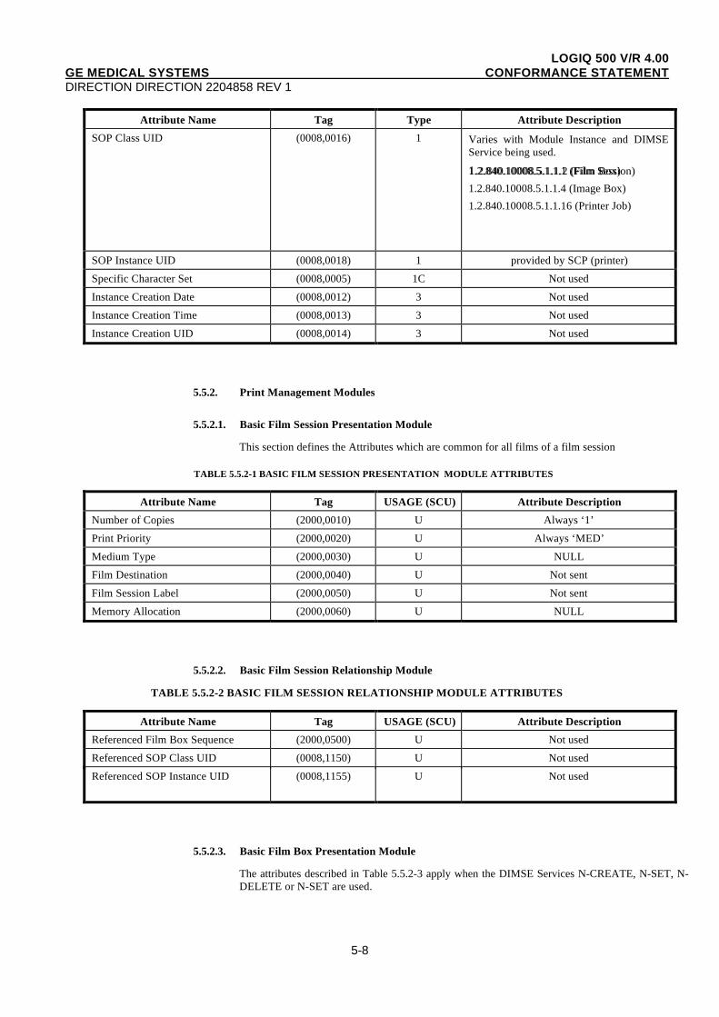
5.5.1.1. SOP Common Module
This section defines the Attributes which are required for proper functioning andidentification of the associated SOP Instances. They do not specify any semantics about theReal-World Object represented by the IOD.
TABLE 5.5.1-1 SOP COMMON MODULE ATTRIBUTES
LOGIQ 500 V/R 4.00GE MEDICAL SYSTEMS CONFORMANCE STATEMENTDIRECTION DIRECTION 2204858 REV 1
5-8
Attribute Name Tag Type Attribute Description
SOP Class UID (0008,0016) 1 Varies with Module Instance and DIMSEService being used.
1.2.840.10008.5.1.1.1 (Film Session)1. 2.840.10008.5.1.1.2 (Film Box)
1.2.840.10008.5.1.1.4 (Image Box)
1.2.840.10008.5.1.1.16 (Printer Job)
SOP Instance UID (0008,0018) 1 provided by SCP (printer)
Specific Character Set (0008,0005) 1C Not used
Instance Creation Date (0008,0012) 3 Not used
Instance Creation Time (0008,0013) 3 Not used
Instance Creation UID (0008,0014) 3 Not used
5.5.2. Print Management Modules
5.5.2.1. Basic Film Session Presentation Module
This section defines the Attributes which are common for all films of a film session
TABLE 5.5.2-1 BASIC FILM SESSION PRESENTATION MODULE ATTRIBUTES
Attribute Name Tag USAGE (SCU) Attribute Description
Number of Copies (2000,0010) U Always ‘1’
Print Priority (2000,0020) U Always ‘MED’
Medium Type (2000,0030) U NULL
Film Destination (2000,0040) U Not sent
Film Session Label (2000,0050) U Not sent
Memory Allocation (2000,0060) U NULL
5.5.2.2. Basic Film Session Relationship Module
TABLE 5.5.2-2 BASIC FILM SESSION RELATIONSHIP MODULE ATTRIBUTES
Attribute Name Tag USAGE (SCU) Attribute Description
Referenced Film Box Sequence (2000,0500) U Not used
Referenced SOP Class UID (0008,1150) U Not used
Referenced SOP Instance UID (0008,1155) U Not used
5.5.2.3. Basic Film Box Presentation Module
The attributes described in Table 5.5.2-3 apply when the DIMSE Services N-CREATE, N-SET, N-DELETE or N-SET are used.
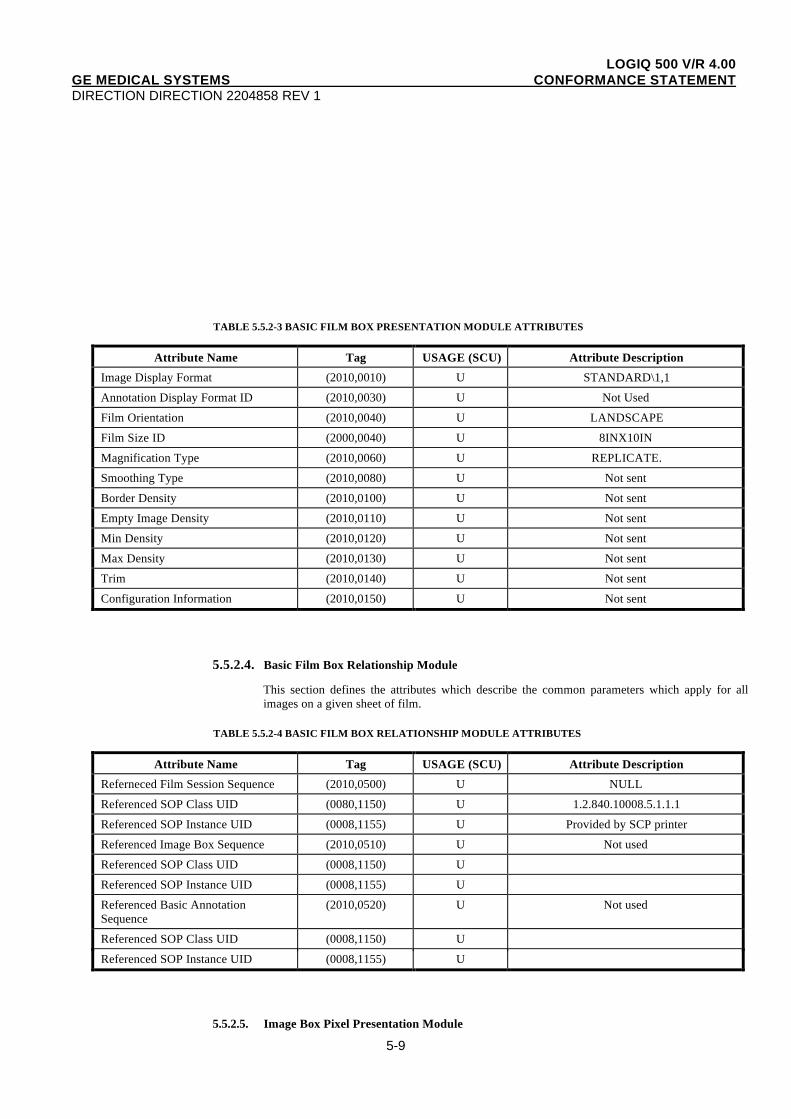
LOGIQ 500 V/R 4.00GE MEDICAL SYSTEMS CONFORMANCE STATEMENTDIRECTION DIRECTION 2204858 REV 1
5-9
TABLE 5.5.2-3 BASIC FILM BOX PRESENTATION MODULE ATTRIBUTES
Attribute Name Tag USAGE (SCU) Attribute Description
Image Display Format (2010,0010) U STANDARD\1,1
Annotation Display Format ID (2010,0030) U Not Used
Film Orientation (2010,0040) U LANDSCAPE
Film Size ID (2000,0040) U 8INX10IN
Magnification Type (2010,0060) U REPLICATE.
Smoothing Type (2010,0080) U Not sent
Border Density (2010,0100) U Not sent
Empty Image Density (2010,0110) U Not sent
Min Density (2010,0120) U Not sent
Max Density (2010,0130) U Not sent
Trim (2010,0140) U Not sent
Configuration Information (2010,0150) U Not sent
5.5.2.4. Basic Film Box Relationship Module
This section defines the attributes which describe the common parameters which apply for allimages on a given sheet of film.
TABLE 5.5.2-4 BASIC FILM BOX RELATIONSHIP MODULE ATTRIBUTES
Attribute Name Tag USAGE (SCU) Attribute Description
Referneced Film Session Sequence (2010,0500) U NULL
Referenced SOP Class UID (0080,1150) U 1.2.840.10008.5.1.1.1
Referenced SOP Instance UID (0008,1155) U Provided by SCP printer
Referenced Image Box Sequence (2010,0510) U Not used
Referenced SOP Class UID (0008,1150) U
Referenced SOP Instance UID (0008,1155) U
Referenced Basic AnnotationSequence
(2010,0520) U Not used
Referenced SOP Class UID (0008,1150) U
Referenced SOP Instance UID (0008,1155) U
5.5.2.5. Image Box Pixel Presentation Module
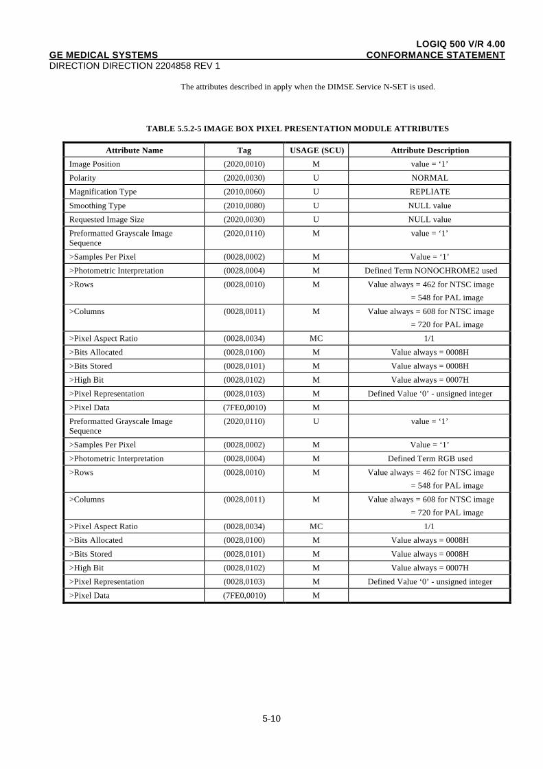
LOGIQ 500 V/R 4.00GE MEDICAL SYSTEMS CONFORMANCE STATEMENTDIRECTION DIRECTION 2204858 REV 1
5-10
The attributes described in apply when the DIMSE Service N-SET is used.
TABLE 5.5.2-5 IMAGE BOX PIXEL PRESENTATION MODULE ATTRIBUTES
Attribute Name Tag USAGE (SCU) Attribute Description
Image Position (2020,0010) M value = ‘1’
Polarity (2020,0030) U NORMAL
Magnification Type (2010,0060) U REPLIATE
Smoothing Type (2010,0080) U NULL value
Requested Image Size (2020,0030) U NULL value
Preformatted Grayscale ImageSequence
(2020,0110) M value = ‘1’
>Samples Per Pixel (0028,0002) M Value = ‘1’
>Photometric Interpretation (0028,0004) M Defined Term NONOCHROME2 used
>Rows (0028,0010) M Value always = 462 for NTSC image
= 548 for PAL image
>Columns (0028,0011) M Value always = 608 for NTSC image
= 720 for PAL image
>Pixel Aspect Ratio (0028,0034) MC 1/1
>Bits Allocated (0028,0100) M Value always = 0008H
>Bits Stored (0028,0101) M Value always = 0008H
>High Bit (0028,0102) M Value always = 0007H
>Pixel Representation (0028,0103) M Defined Value ‘0’ - unsigned integer
>Pixel Data (7FE0,0010) M
Preformatted Grayscale ImageSequence
(2020,0110) U value = ‘1’
>Samples Per Pixel (0028,0002) M Value = ‘1’
>Photometric Interpretation (0028,0004) M Defined Term RGB used
>Rows (0028,0010) M Value always = 462 for NTSC image
= 548 for PAL image
>Columns (0028,0011) M Value always = 608 for NTSC image
= 720 for PAL image
>Pixel Aspect Ratio (0028,0034) MC 1/1
>Bits Allocated (0028,0100) M Value always = 0008H
>Bits Stored (0028,0101) M Value always = 0008H
>High Bit (0028,0102) M Value always = 0007H
>Pixel Representation (0028,0103) M Defined Value ‘0’ - unsigned integer
>Pixel Data (7FE0,0010) M
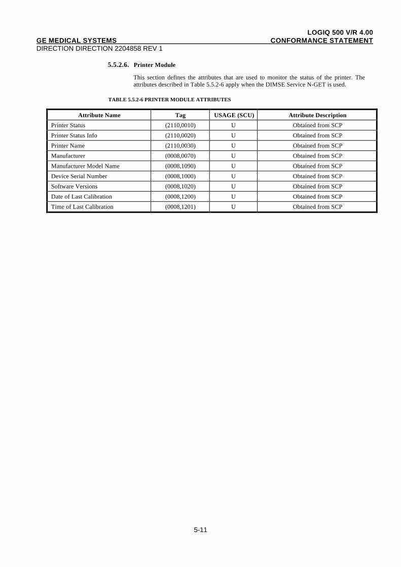
LOGIQ 500 V/R 4.00GE MEDICAL SYSTEMS CONFORMANCE STATEMENTDIRECTION DIRECTION 2204858 REV 1
5-11
5.5.2.6. Printer Module
This section defines the attributes that are used to monitor the status of the printer. Theattributes described in Table 5.5.2-6 apply when the DIMSE Service N-GET is used.
TABLE 5.5.2-6 PRINTER MODULE ATTRIBUTES
Attribute Name Tag USAGE (SCU) Attribute Description
Printer Status (2110,0010) U Obtained from SCP
Printer Status Info (2110,0020) U Obtained from SCP
Printer Name (2110,0030) U Obtained from SCP
Manufacturer (0008,0070) U Obtained from SCP
Manufacturer Model Name (0008,1090) U Obtained from SCP
Device Serial Number (0008,1000) U Obtained from SCP
Software Versions (0008,1020) U Obtained from SCP
Date of Last Calibration (0008,1200) U Obtained from SCP
Time of Last Calibration (0008,1201) U Obtained from SCP