Embed Size (px)
Citation preview
THE AMERICAN INSTITUTE OF MINING AND METALLURGICAL ENGINEERS
Technical Publication No. 2 6 3 Class E, Institlite of Metals, No. 91
Stress-corrosion Cracking of Annealed Brasses ,
By ALAN MORRIS BRIDGEPORT, CONN.
DISCUSSION OF THIS PAPER IS INVITED. I t should prefer- ably be presented in person a t the New York Meeting. Fehruary, 1930, when an abstract of the paper will be presented. If this is im- possible. discussion in writing may be sent to the Editor, American Institute of Mining and Metallurgical Engineers, 29 West 39th Street, New York. N. Y., for presentation by the Secretary or other representative of the author. Unless special arrangement is made, the discussion of this paper will close April I. 1930. Any discus- sion offered thereafter should preferably bein the form of a new paper.
29 W E S T 3 g t h S T R E E T . N E W Y O R K , N . Y .
,111 papers issued b y the Ilastitule are nbstrocted t n o l ~ t h b y w ~ o ~ t l h i n i l f in ing rind M~L~LIIuT!I!I. ?'hi8 l ~ n p e r i s issued wi th the J a n u a r y , 1030, warrabor. dletrabers ore ~ ~ r g e d lo go lhrot~gh the nbstracts enck nro,~th a ~ t d select rind request such l ~ n p e r s a s theg car1 u s e .
Copyright, 1930. by the,American Institute,of Mining an3 Metallurgical Engineers, Inc. Prlnted In U. S. A.
Papers presented before the meetings of the Institute and accepted for publication are numbered and issued individually as TECHNICAL PUBLICATIONS. They are clas- sified in one or more series according to subject and numbered consecutively in each.
Members of the Institute are invited to register for the receipt of papers in such class or classes as may be of interest to them or to order individual publications by number. Each month a list of new publications is issued in MINING AND METALLURGY. Prior to July I , 1 9 2 7 , the papers were issued as individual pamphlets with class letters but without class numbers. A com- plete list of those published January to June, 1 9 2 7 , inclusive, appeared in MINING AND nrETALLuRGY for July, 1 9 2 7 , in the advertising pages; those published July to December, inclusive, in MINING AND METALLURGY for December, 1 9 2 7 , also in the advertising pages. In a similar manner, the complete lists are published in July and December for each year.
Papers presented before the three Divisions, the Insti- tute of Metals, the Petroleum Division and the Iron and Steel Division, are assembled, bound and distributed to the members of tbose Divisions. Temporary binders suit- able for holding the papers of any one or more classes will be furnished members at cost, $ 1 . 2 5 each.
The Institute also issues MINING AND METALLURGY, a monthly publication; an annual Yearbook, and one or more volumes of TRANSACTIONS containing those papers that are of most general interest. These go to all mem- bers but not all papers issued as TECHNICAL PUBLICATIONS
are reprinted in TRANSACTIONS.
Members are therefore urged to save their TECHNICAL
PUBLICATIONS.

Stress-corrosion Cracking of Annealed Brasses
BY ALAN ORRIS,* BRIDGEPORT, CONN.
(Nerr York Meeting, February, 1030)
SEASON cracking of brass has received wide attention and there is a wealth of technical literature on the subject. I ts causes are fairly well understood and means for its prevention are inexpensive and effective, so that the frequency of failures from this source has diminished of recent years. But its sister phenomenon, the failure of annealed brass by reason of applied tensile stress plus a certain type of corrosion, has received less attention, though it has been responsible for occasional more .or less troublesoille cases of cracking of brass in service. The work described in the following pages was undertaken about two years ago to determine the relative resistance of various commercial brass mixtures to stress-. corrosion cracking, and to learn something of the controlling factors. By stress-corrosion cracking we mean the cracking of brass free. from internal stresses by reason of applied tensile stress and sin~ultaneous attack by certain corrosive agents.
Rogers,' in discussing a paper by Hatfield and Thirkell, says: "He had also applied a solution of mercuric salt to tensile test pieces of brass whilat tlley were under stress. in the testing machine. At very moderate stresses such test pieces cracked, and very readily broke."
Moore, ~eckinsa le and Mallinso.n2 subjected test pieces to simultane- ous corrosion and tensile stress. I n order to determine the minimum stress detectable in brass by the mercurous'nitrate test, tensile sanlples were placed under stress and treated with lnercurous nitrate solution. They found thnt brass stressed below a minimum did not crack.
Dr. McAdam3 has investigated the effect of corrosion on the fatigue limit of brasses, anlong other materials. He directed a stream of either fresh or ,salt mater against the specimen while i t was undergoing fatigue test. The corrosion-fatigue limits thus determined nlay be considerably lower than the endurance limit without coincident corrosion. The exact
* Rcscarch ~ n g i n c e r , Bridgeport Brass Co. F. Rogers: Discussion on Scason cracking. Jnl. Inst. Metals (1919) 22, 114. . H. Moore, S. B. Becltinsalc and C. E . Mdlinson: Scnson Cracking of Brass and
Coppcr AHoys. J,ILL. Inst,. Metals (1921) 26, 86. P. J. McAdanl, Ji.: Fatigue and Corrosion-fatigue of Mctals. Intl. Congress for
Testing Mnl;eri~~ls, Amsterdat~~, 1927. 3
relationship, if any. between this form of failure and stress-corrosion cracking has not been determined. I n the case of corrosion-fatigue, failure is caused by simultaneous application of repeated stress and corrosion of a general type. The phenomenon is not confined to copper alloys. I n stress-corrosion, failure is brought about by static tensile stress and corrosion of a highly special nature. Only certain metals are affected by it. It is to be hoped that future work will throw light on the relation between these two types of failure.
It seems probable that season cracking and applied stress-corrosion cracking are manifestations of the same phenomenon. Moore, Beckin- sale and Mallinson have used the term "season cracking" to cover both when they say '(Season cracking occurs only in material which is maintained in a state of stress, either by external constraint or more commonly by internal stres8." Many of the facts established by investi- gation of season cracking undoubtedly apply with equal force to both, but i t is dangerous to infer too close a similarity in the relative suscepti- bility of various mixtures to the two types of attack. The tendency of a brass to season-crack under given corrosive conditions is a function of its inherent susceptibility to stress-corrosion attack and also of the inagni- tude of the internal stresses set up in i t by a given cold-working operation. This latter factor probably varies with the physical characteristics of the inixtures. It is conceivable that in two alloys that offer equal resistance to stress-corrosion attack, difference in ductility and elastic properties would cause one to season-crack more readily than the other. Because of this complication and the conlparative difficulty of obtaining accurate measurements of internal stresses, i t was decided to attack the problem by observing the way in ~vhich various mixtures reacted to applied stres. plus the proper type of corrosion.
The apparatus used is shown in Fig. 1. It consisted merely of a series of levers by means of which tensile stresses might be applied to a series of samples.
Fig. 2 shows in detail the manner in which each test piece is set up. The lower end passes through a hole in the angle. The nut on the lower end of the piece has a spherical face which sets into a corresponding socket in the angle, making small angular movement of the piece possible. The upper end of the piece passes through a hole in the lever, and through a block of steel so shaped as to provide an obtuse knife-edge rest, which allo~vs for angular movement of the lever. Thus substantially axial loading of the test piece is provided. The angular movement of the lever is always s~nal l 'because the breaks are accoinpanied by little or no elongation.

ALAN MORRIS 5
The shank,
corrosive agent-is contained in a glass tube surrounding closed top and bottom by rubber stoppers through which
a
. .
the the
shank passes ... The upper stopper is split for ease of installation, and is pierced by a fine copper tube. The results of preliminary experiments,
. .
. .
. FIG. 2.-TEST PIECE SET UP.
made before the installation of these fine tubes, left something to be desired as to uniformity and reproducibility. . After their. introduction,
6 STRESS-COR~~OSION CRACKING OF ANNEALED BRASSES
hon~ever, results were much better. Their effect may be to equalize pressure, or more probably to allow access of a-little air to the corrosion chamber, or both.- ' .
Of the many. corrosive agents tried by Rfoore, Beckinsale and R/Iallinsonf they found that only ammonia, a~nnlonium nitrate and mercury would induce season cracking in stressed brass. They detected "ammonia in a water extract of slightly corroded fractures caused by season cracking in brass corroded by atmospheric action only." They concluded that "it is probable that traces of ammonia in the atmosphere are an important agency and possibly the main agency, producing season cracking of stressed brass." They say "it is probable that the behavior of a copper alloy submitted to the coinbilled effect of tension and of aminonia or mercury is a reliable index of its liability to fail by season cracking. " preliminary expcri~nents showed that more concord- an t results could be obtained by the use of ammonia than were produced by mercury. Accordingly ammonia was chosen for these tests.
The test pieces are prepared from )$in. round rod. A piece 634 in. long is threaded a t each end to take the nuts. A central section 3f4 in. long is turned to ?$-in. dia. The test pieces are then annealed as desired. All pieces are pickled for 20 sec. in 40.0 per cent. nitric acid and quickly and thoroughly washed just before installation. They are ihen set up in the testing apparatus and weights are hung on the lever to give the required stress. The ammonia is placed in the tube surrounding the shank of the test piece and the top stopper inserted.
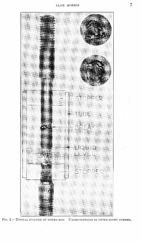
Fig. 3 shows a typical failure produced in the tests reported here. The cracks generally appear on the part of the shank that is within the corrosion chamber, above the level of the liquid. The cracks are always circu~nferential, lying in a plane perpendicular to the direction of applied stress. Exaillinatio~l of the broken surface shows that the cracks causing failure generally extend inward from the surface about an equal dis- tance a t all parts of the circumference.
As the cracks deepen, the stress on the still unattacked portion of the cross-section (upper right corner of Fig. 3) rises, because the load on the specimen rc~nains constant. Failure occurs when this stress reaches a value probably less than the ultimate strength of the material (as shown in
* H. Moore, S. B. Beckinsale and C. E. Mallinson: Op. cit.

8 STRESS-CORROSlON CRACKING O F ANNEALED BRASSES
a tensile testing machine) by an amount of which the magnitude is determined , by the stress-concentrating effect of the stress-cor- rosion cracks.
In the case of soft ductile annealed brasscs, this effect is probably not large. I n order to test this point, sarnples showing circumferential marks wcre testcd under the same conditions as some that had bccn rubbed lorigitudinally with emcry papcr. No differencc in their bchav- ior was noted; ncither could it be scen that the cracks followed the tool marks.
The inethod adoptcd for studying the reaction of any particular alloy mias to prepare a number of samples as ncarly idcntical as possiblc in shape and structure. These wcre sct up urldcr ~ a r i o u s stresses, time before failure bcing notcd. Whcn strcss as ordinate is plotted against time before failure as absissa on ordinary cartcsian coordinate paper, the resulting curve slopes stceply downward from the lcft, flattcns out and secnls to approach a horizontal. Whcn thc same data are plottcd on semilog paper, the curve becomes a scries of straight lincs (within the range of stresscs uscd), not like the usual stress-cycle curve of the fatigue te'st. The curvc descends steeply to a stress a t or near the ylcld point of the material. Here it changcs direction abruptly, procceding as a straight line of lesser slope, which continues downward to a stress bclolir which the rnaterlal does not fail by stress-corrosion, a t least within the time the samples were kept under tcst in this worli.
All curvcs shown here are plotted on ordinary cartesian coordinate paper, as the author fecls that in this forin a truer sense of the relation is imparted. He does not bclieve that the horizontal approachccl by the curve is necessarily a safe working stress for the material, though this may prove to bc the case. In scrvicc failures othcr factors inay entcr, such as ir~terlnittent loading, vibration and temperature change. In this work thc curves are used only to comparc resistances of materials differing in analysis and structurc. .
In all of these tests, the sizc of the specilllcn and the corrosive condi- tions have been kept constant. Mixture; stress and structure arc the independent variables. I n all cases time before failure is the dependent variable noted. Our objcct is to coinpare thc resistance of thc various sanlples to stress-corrosion attack by comparing the brcaking times under like corlditions of stress and corrqsion. Rut breaking time will bc a mcasurc of resistance only when the salnples in question have approxi- mately cqual tensile .strength. Ilnagine two materials of diffcrent
ALAN hlORliIS 9
tensile strength, which would be attacked with equal rapidity. The material of higher tensile strength would hold up longer under like con- ditions of stress and corrosion, and appear to resist the action better than the weaker one, if time only were used as the criterion.
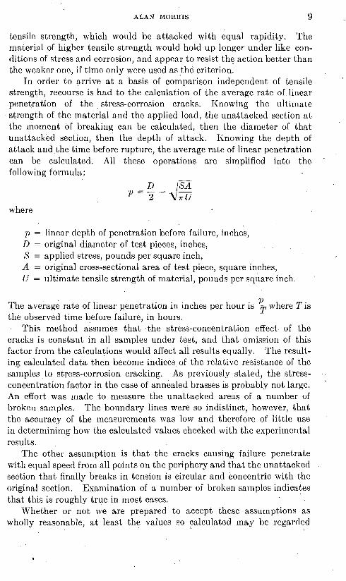
In order to arrive a t a basis of comparison independent of tensile strength, recourse is had to the calculation of the average rate of linear penetration of the stress-corrosion cracks. Knowing the ultimate strength of the material and the applied load, the unattacked section a t the moment of breaking can be calculated, then the diameter of that unattacked section, then the depth of attack. Knowing the depth of attack and the time before rupture, the average rate of linear penetration can be calculated. All these operations are simplified into the following forniula :
where
p = linear depth of penetration before failure, inches, D = original diameter of test pieces, inches, . .
,C = applied stress, pounds per square inch, A = original cross-sectional area of test piece, square inches, U = ultimate tensile strength of material, pounds per square inch.
P The average rate of linear penetration in inches per hour is - where T is the observed time before failure, in hours.
T
This method assumes that the stress-concentration effect of the cracks is constant in all samples under test, and that omission of this factor from the calculations would affect all results equally. The result- ing calculated data then become indices of the relative resistance of the samples to stress-corrosion cracking. As previously stated, the stress- concentration factor in the case of annealed brasses is probably not large.
.
An effort was made to measure the unattacked areas of a number of broken samples. The boundary lines were so indistinct, however, that the accuracy of the measurements was low and therefore of little use in deterrninimg how the calculated values checked with the experimental results.
The other assun~ption is that the cracks causing failure penetrate with equal speed from all points on the periphery and that the unattacked section that finally breaks in tension is circular and concentric with the original section. Examination of a number of broken sainplcs indicates that this is roughly true in most cases.
Whether or not we are prepared to accept these assumptions as wholly reasonable, a t least the values so calculatcd may be regarded
10 - '
STRESS-CORROSION CRACKING O F ANNEALED BRASSES
temporarily as index numbers representative of the relative resistance of the samples.
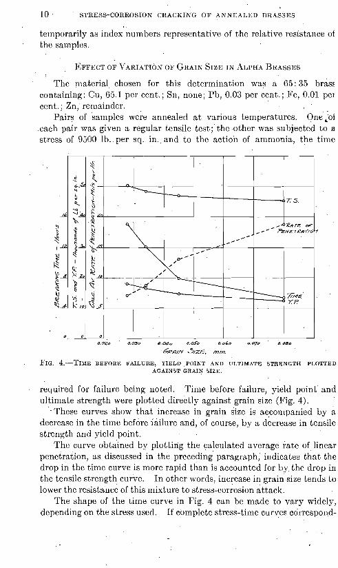
The material chosen for this determination was a 65: 35 brass containing: Cu, 65.1 per cent.; Sn, none; Pb, 0.03 per cent.; Fe, 0.01 per cent.; Zn, remainder.
Pairs of samples were annealed a t various temperatures. One ,of each pair was given a regular tensile test; the other was subjected to a stress of 9500 lb. per sq. in. and to the action of ammonia, the time
6em-f S/ZE, mm.
FIG. 4.-TIME BEFORE FAILURE, YIELD POINT AND ULTIMATE STRENGTH PLOTTED AGAINST GRAIN SIZE.
required for failure being noted. Time before failure, yield point' and ultimate strength were plotted directly against grain size (Fig. 4).
' .These curves show that increase in grain size is ncconipanied by a decrease in the time before iailure and, of course, by a decrease in tensile strength and yield point.
The curve obtained by plotting the calculated average rate of linear peneiration, as discussed in the preceding paragraph, indicates that the drop in the time curve is more rapid than is accounted for by, the drop in the tensile strength curve. I n other words, increase in grain' size tends to lower the resistance of this mixture to stress-corrosion attack.
The shape of the time curve in Fig. 4 can be made to vary widely, depending on the stress used. If complete stress-time curyes correspond-
ALAN MORRIS 11
ing to various grain sizes were prepared, there would be a seriesof curves, one above the other a n d approaching one another a t the left-hand or steep end. In Fig. 4 the points where the horizontal line representing the stress cuts each of these curves are determined. If a higher stress had been used,'the curye would be flatter and lower; with a lower stress, the curve would have risen more steeply toward the left and been generally higher. This same principle applies to Fig. 7.
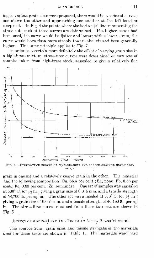
In order to ascertain more definitely the effect of varying grain size in a high-brass mixture, stress-time curves were determined on two sets of samples taken from high-brass stock, annealed to give a relatively fine
BREAKING T;ML - HOUT~
FIG. 5.-STRESS-TIME CURVES O F FINE-GRAINED AND COARSE-GRAINED HIGH-BRASS STOCK.
grain in one set and a relatively coarse grain in the other. The material had the following composition: Cu, 66.4 per cent.; Sn, none; Pb, 0.58 per cent.; Fe, 0.03 per cent. ; Zn, remainder. One set of samples was annealed a t 500" C. for 35 hr., giving a grain size of 0.015 mm. and a tensile strength of 53,700 lb. per sq. in . The other set was annealed a t BEOO C. for $4 hr.; giving a grain size of 0.064 min. and a tensile strength of 46,100 lb. per sq. in. The stress-tike curves obtained from these two sets are shos~n in Fig. 5.
The compositions, grain sizes and tensile strengths of the materials used for these tests are sho\vn in Table 1. The materials were hard
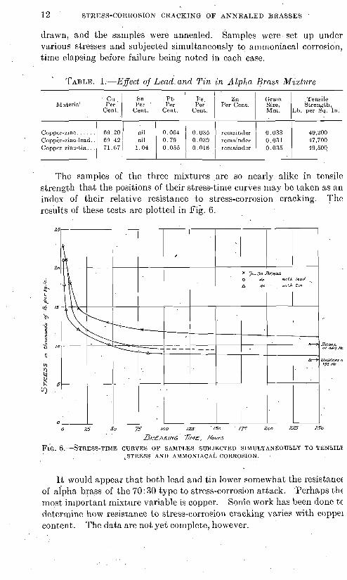
12 STRESS-CORItOSION CRACKING O F ANNEALED BRASSES
drawn, and the samples were annealed. Sanlples were set up under va.rious stresses and subjected simultaneously to alnlnoniacal corrosion, timc elapsing before failure being noted in each case.
TABLE. 1.-E,ffect of ~ e a d : and T in in Alpha Brass Miztztre 1
-
C u , Sn Pb 1 I'e Zn I Grain Tensile Material f i r I i'er 1 f i r lie. Per Cent. Size Strength,
Cent. Cent. Cent. Cent. MII I Lb. per Sq. In .
The samples of the three mixtures are so nearly alike in tensile strength that the positions of their stress-time curves may be taken as an index of their relative resistance to stress-corrosion cracking. The results of these tests are plottetl in Fig. 6.
Copper-zinc . . . . .
FIG. ~.-STRESS-TI&~E CUIZVES OF SAMPLES SUB.1ECTED SlMULTANEOUSLY TO TENSILX ,STRESS ANI) AA~MONIACAL CORROSION. .
60.20 / Ail I O O B ~ ' 0,031 ren~r inder ' 0.033 40,200
It would appear that both lead and tin lower somewhat the resistance of alpha brass of the 70: 30 type to stress-corrosion attack. Perhaps thc most important mixture variable is copper. Sonie work has been done t c determine how resistance t o stress-corrosion cracking varies with coppel content. The data are not yet complete, however.
CoppEr-zinc-lcad.. 60.41 nil ( 0.79 0.030 remainder 47,700 Coppcr-lnc-tin. . . , 71.67 1 1.04 1 0.055 1 0.016 1 remainder 1 ::::: 1 40,.50Q

ALAN MORRIS 13
The first few exploratory tests made'with brass of the Muntz metal type indicated that its structure affected its resistance to 'a marked degree. The material used was of the following composition: Cu, 60,85 per cent.; Sn, 0.08; Pb, 0.28;.Fe, 0.036; Zn, remainder. The first reconnais- sance test consisted of heating pairs of cold-worked samples to tempera- tures high enough to produce a large amount of beta, quenching one of each pair in water and allowing the other to cool slowly in the furnace. When these pairs were tested under similar conditions of stress and cor-
Qu~ncx/nc ENPERATU~E, DL&. C.
FIG. 7.-STRESS-TIME CURVES O F QUENCHED SAMPLES SUB.JECTED TO AMMONIACAL CORROSION.
rosion, it was found that-in each case the quenched sample outlasted the slowly cooled one. It is interesting to note that miscroscopic examination in each case showed that the slowly cooled sample that had failed most rapidly contained more alpha than the corresponding quenched sample, but that this alpha was of the .familiar lamellar form taken by alpha that is reprecipitated from beta during slow cooling.
As we were interested in determining how to bring about the highest possible resistance to stress-corrosion cracking, and as the first few exploratory tests indicated that quenching increased resistance, samples were quenched from various temperatures ranging from 500" to 800" C. They were then subjected to a stress of 14,700 lb. per sq. in. and to ammoniacal corrosion. The time before failure is shown in Fig. 7, plotted

14 STRESS-CORROSION CRACKING OF ANNEALED BRASSES :
against the quenching temperature. This curve indicates that of the temperatures tried the one quenched from 500' C. showed the greatest resistance.
Two sets of samples were then prepared, one being quenched from 500' C., the other being air-cooled from the same temperature. The quenched samples had a tensile strength of 58,850 lb. per sq. in. The strength of the air-cooled samples was a little lower, that is, 55,900 lb. per sq. in. Colnplete stress-time curves were determined for these two sets (Fig. 8).
Samples were prepared from a naval brass of the following composi- tion: Cu, 60.28 per cent.; Sn, 0.75; Pb, 0.11; Fe, 0.016; Zn, remainder. Samples were held a t various temperatures ranging from 500' to 800" C. for 45 hr. and quenched in water. They were then subjected to stress of 14,700 lb. per scl. in. and to amnloniacal corrosion. The tinlc before failure in each case was plotted against the quenching temperature (Fig. 7).
Samples of this mixture were heated to 500' C. and quenched in water, and a stress-time curve was determined (Fig. 9). The tensile strength of these samples was 66,400 lb. per sq. in. Comparison 01 this curve with the curve for quenched Muntz metal shown in Fig. 8 shows that this mixture developed a higher resistance than did the Muntz metal:

ALAN MORRIS 15
Other samples were made up from another lot of raw material of nearly the same analysis as the preceding; i. e . , Cu, 59.45 per cent.; Sn, 0.73; Pb, 0.078; Fe, 0.017; Zn, remainder. Samples of this material were heated for $d hr. a t 500" C. and allowed to cool freely in air. Their tensile strength mas 64,000 lb. per sq. in. (Lower curve in Fig. 9.)
BEEAKING T/NE - H O U ~ S .
FIG. 9.-STRESS-TIME CURVES OF QUENCHED AND AIR-COOLED SAMPLES OF NAVAL BRASS.
1. Coarse grain in so-called "high brasses" appears to lower the resistance of the piece to stress-corrosion attack.
2. Lead and tin in an alpha brass tend also to make the material a little less resistant to this form of attack.
3. The resistance of a Muntz metal, and naval brass (and probably )f manganese bronze), is materially increased by quenching fro111 a reason- tbly low annealing temperature.
The writer does not feel that these tests constitute more than a general *econnaissance of the field. The results are presented in the hope that ,heir discussion will hold suggestions that will serve as a guide to further ~ o r k of this nature.