Embed Size (px)
Citation preview

D-17Disc Screen Hydrocyclone Media
Disc Filters � Spin Klin � 3” Crystal
�������������� ���������������������
No. of units 3 4 5 6 7 8 3 4 5 6 7 8
Filtration Grade Water Quality m3/h gpm
400-130 µ
Good 110 148 185 222 259 296 484 652 814 977 1140 1302Average 90 120 150 180 210 240 396 528 660 792 924 1056Poor 66 88 110 132 154 176 290 387 484 581 678 774Very Poor 45* 60 75 90 105 120 198* 264 330 396 462 528
100 µ
Good 90 120 150 180 210 240 396 528 660 792 924 1056Average 66 88 110 132 154 176 290 387 484 581 678 774Poor 48* 64 80 96 112 128 211* 282 352 422 493 563Very Poor 33* 44* 55 66 77 88 145* 194* 242 290 339 387
55 µ
Good 60 80 100 120 140 160 264 352 440 528 616 704Average 48* 64 80 96 112 128 211* 282 352 422 493 563Poor 36* 48* 60 72 84 96 158* 211* 264 317 370 422Very Poor 27*** 36** 45* 54 63 72 119*** 158** 198* 238 277 317
20 µ
Good 30*** 40** 50 60 70 80 132*** 176** 220 264 308 352Average 24*** 32*** 40** 48* 56 64 106*** 141*** 176** 211* 246 282Poor 18*** 24*** 30*** 36*** 42* 48* 79*** 106*** 132*** 158*** 185* 211*Very Poor 12*** 16*** 20*** 24*** 28*** 32*** 53*** 70*** 88*** 106*** 123*** 141***
�������
�Precise filtration with Spin Klin technology�Automatic filtration for medium flow rates �Continuous flow during backwash�Plastic parts - corrosion free�Highly durable filter element�Easy installation and operation�Lightweight, compact design�Simple and reliable operation
F i l t r a t i o n B a t t e r i e s
���� �������
METRIC USMax. pressure bar 10 psi 145Min. backwash pressure bar 2.8 psi 40.6Filtration surface area per unit cm2 1760 in2 272.8Filtration volume per unit cm3 2640 in3 161Backwash water volume per unit lit 66 gal 17.4
* External source for backwash is necessary
** When pressure is low, it is necessary to close downstream valve during backwash
*** The 2" Spin Klin Battery is recommended
w w w . p e l m a r e n g . c o mD-18
��������������������� !"�#""$% ��� �&��
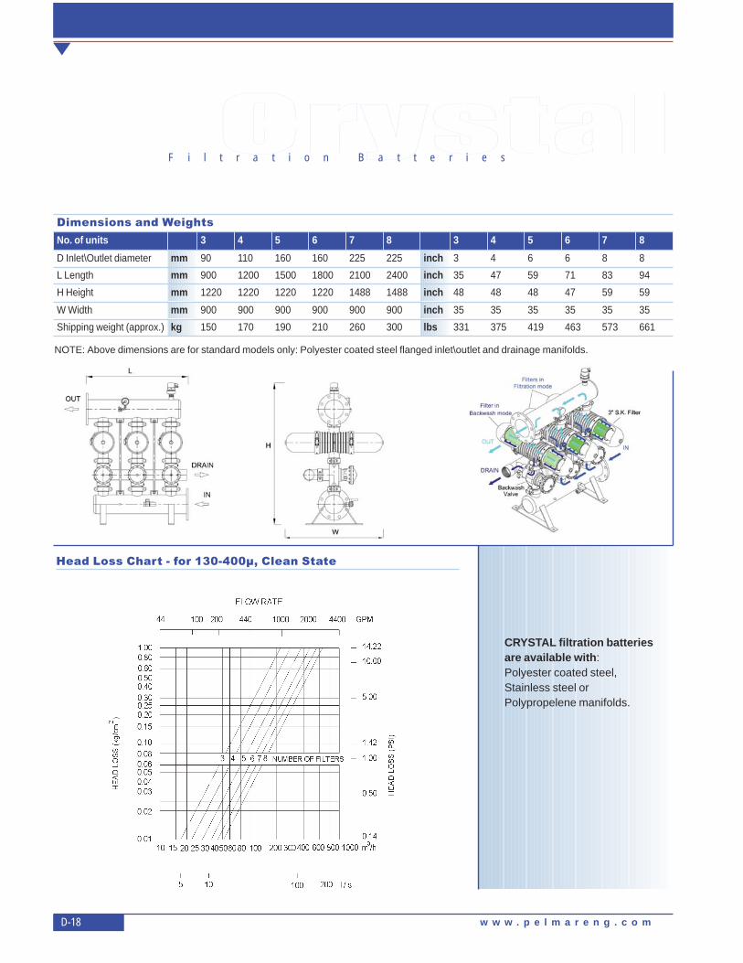
CRYSTAL filtration batteriesare available with:Polyester coated steel,Stainless steel orPolypropelene manifolds.
�������F i l t r a t i o n B a t t e r i e s
���� ��� ��� �����'��
No. of units 3 4 5 6 7 8 3 4 5 6 7 8
D Inlet\Outlet diameter mm 90 110 160 160 225 225 inch 3 4 6 6 8 8
L Length mm 900 1200 1500 1800 2100 2400 inch 35 47 59 71 83 94
H Height mm 1220 1220 1220 1220 1488 1488 inch 48 48 48 47 59 59
W Width mm 900 900 900 900 900 900 inch 35 35 35 35 35 35
Shipping weight (approx.) kg 150 170 190 210 260 300 lbs 331 375 419 463 573 661
NOTE: Above dimensions are for standard models only: Polyester coated steel flanged inlet\outlet and drainage manifolds.
3” Spin Klin BatteryOperation and Maintenance Manual
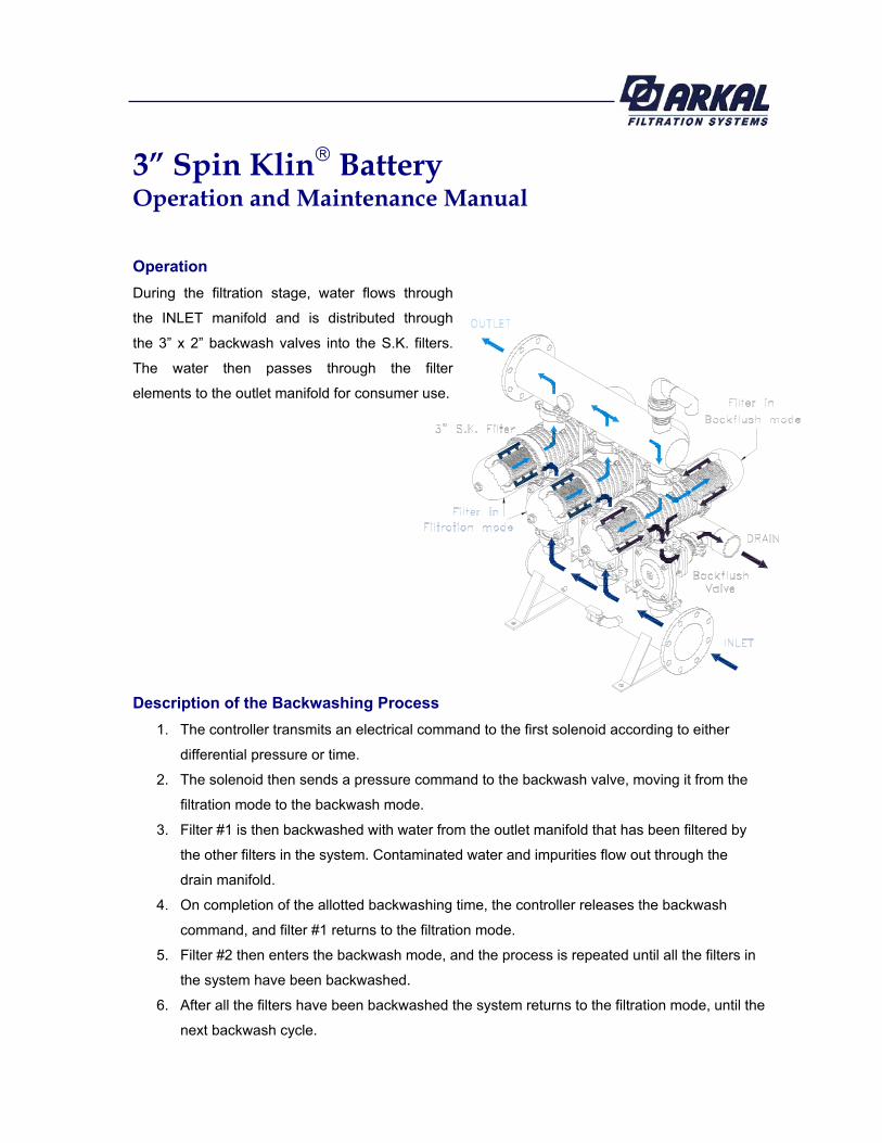
Operation
During the filtration stage, water flows through
the INLET manifold and is distributed through
the 3” x 2” backwash valves into the S.K. filters.
The water then passes through the filter
elements to the outlet manifold for consumer use.
Description of the Backwashing Process
1. The controller transmits an electrical command to the first solenoid according to either
differential pressure or time.
2. The solenoid then sends a pressure command to the backwash valve, moving it from the
filtration mode to the backwash mode.
3. Filter #1 is then backwashed with water from the outlet manifold that has been filtered by
the other filters in the system. Contaminated water and impurities flow out through the
drain manifold.
4. On completion of the allotted backwashing time, the controller releases the backwash
command, and filter #1 returns to the filtration mode.
5. Filter #2 then enters the backwash mode, and the process is repeated until all the filters in
the system have been backwashed.
6. After all the filters have been backwashed the system returns to the filtration mode, until the
next backwash cycle.

Spin Klin Technology- Spin Klin Spine Model 2
General:
The Spin Klin discs are stacked on the Spin Klin spine.
The discs are color-coded by micron size, and are assembled
according to your water filtration requirements. The spine
assembly has a spring compression unit and an internal piston
which are used to alternately compress and release the discs
during filtration and backwash cycles.
Filtration Mode:
During the filtration process the filter discs are tightly compressed
together by the spring and the differential pressure, forcing the
water to flow through the grooves and traps of the discs.
Backwash Mode:
During backwash the discs are released by releasing the inlet
hydraulic pressure. Multi-jet nozzles provide tangential spray on
the loosened discs, causing them to spin, and release the
retained solids, which are flushed out to the drain.
3” x 2” Backwash Valve
Filtration Position:
Water flows from port A (main supply) to port B
(filter connection). Port C (drain water outlet) is
closed by the seal.
Backwash Position:
Command pressure is applied to the top side of the
diaphragm through port D.The diaphragm moves down,
pushing the sealed body by the shaft. Port A is closed
by the seal, preventing flow to the filter.
Port C is now open allowing flushing water to flow from
port B (filter connection) to the drain.
Filtration Mode Backwash Mode
OUTLET
INLET
BACKWASH WATER INLET
TO DRAIN
Dorot 3”x 2” valve Bermad 3”x 2” valve
A
C
B
D
A
C
B
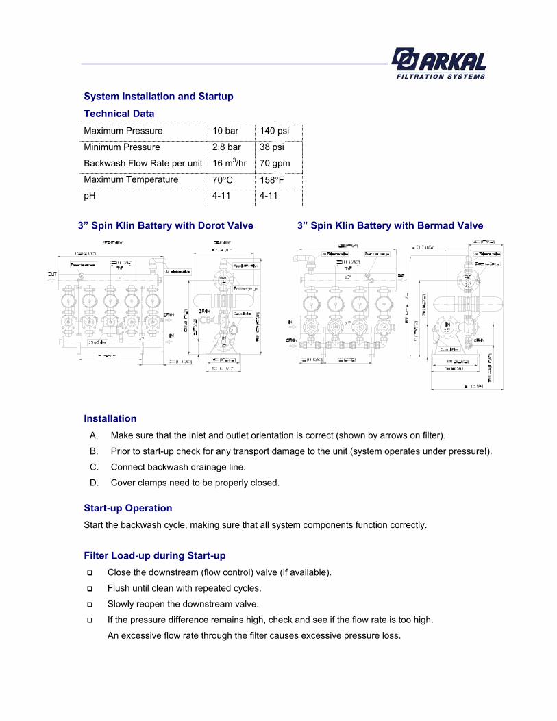
System Installation and Startup
Technical Data
Maximum Pressure 10 bar 140 psi
Minimum Pressure 2.8 bar 38 psi
Backwash Flow Rate per unit 16 m3/hr 70 gpm
Maximum Temperature 70 C 158 F
pH 4-11 4-11
Installation
A. Make sure that the inlet and outlet orientation is correct (shown by arrows on filter).
B. Prior to start-up check for any transport damage to the unit (system operates under pressure!).
C. Connect backwash drainage line.
D. Cover clamps need to be properly closed.
Start-up Operation
Start the backwash cycle, making sure that all system components function correctly.
Filter Load-up during Start-up
Close the downstream (flow control) valve (if available).
Flush until clean with repeated cycles.
Slowly reopen the downstream valve.
If the pressure difference remains high, check and see if the flow rate is too high.
An excessive flow rate through the filter causes excessive pressure loss.
3” Spin Klin Battery with Dorot Valve 3” Spin Klin Battery with Bermad Valve

Control
Refer to the manufacturer’s handbook before installing the controller.
Make sure that the voltage of both the solenoid unit and controller are correct.
Set the manual operation button to automatic.
Check that the P hydraulic switch HIGH and LOW pressure lines are correctly
connected to the appropriate ports.
Set the starting backwash switch to P 5-7 meters (6 - 8p.s.i.).
Set the controller to a flush time of 30 seconds and a dwell time of 10 seconds. These
settings may require adjustment to conform to local water conditions. Typically, a 1 to 3
hour interval between backwashes is recommended.