Embed Size (px)
Citation preview

JungleMUX SONET Multiplexer
86445 2W FXS/PLAR UNIT
334422--8866440000--444455PPSS IIssssuuee 44..00 OOccttoobbeerr 22000066
Technical Practice and
Installation Manual
Copyright © GE Multilin Inc. 2002

342-86400-445PS Issue 4.0 October 2006 Page 2
Copyright GE Multilin Inc. 2002
JungleMUX SONET Multiplexer Technical Practice and Installation Manual Copyright GE Multilin Inc. 2002, All Rights Reserved The copyright of this document is the property of GE Multilin Inc. This document must not be copied, reprinted or reproduced in any material form, either wholly or in part, without the written consent of GE Multilin Inc. GE Multilin Inc. reserves the right to make changes and modifications to any part of this document without notice. GE Multilin Inc. is not responsible for any damages or losses incurred as a result of out-of-date or incorrect information contained in this document.
342-86400-445PS Issue 4.0 October 2006 Page 3
Copyright GE Multilin Inc. 2002
TABLE OF CONTENTS
SECTION PAGE
PART 1 86445-31 2W FXS/PLAR Unit (Single-Channel)
1.1 INTRODUCTION..............................................11 Related Publication and Documentation Support............................11 Handling and Packing.........................................................................12
1.2 UNIT OVERVIEW.............................................13 Test Features.......................................................................................14
1.3 FRONT PANEL FEATURES ...........................15 LED Indications ...................................................................................15 Bantam Jack ........................................................................................15 Push-button (ACK)..............................................................................15 Craft Interface (C.I.) Jack....................................................................16
1.4 UNIT DESCRIPTION .......................................17 Transmit Voice Path............................................................................17 Receive Voice Path .............................................................................18 Transmit Signaling..............................................................................19 Receive Signaling ...............................................................................19 Ringing Generator Sub-Assembly.....................................................20 Microprocessor Operation .................................................................20
1.5 INSTALLATION...............................................22 Pre-installation ....................................................................................22 Shelf Position ......................................................................................23 Power Requirements ..........................................................................24
342-86400-445PS Issue 4.0 October 2006 Page 4
Copyright GE Multilin Inc. 2002
SECTION PAGE
Inserting the Unit in the Shelf ............................................................24 Removing the Unit from the Shelf .....................................................24 Paddleboard Connections..................................................................25
Paddleboard Installation................................................................... 25
1.6 CONFIGURATION...........................................26 General Information ............................................................................26
Context-Sensitive Help ..................................................................... 28 Configure button ............................................................................... 28 Undo button ....................................................................................... 28 Cancel button..................................................................................... 28 Copy and Paste buttons ................................................................... 28
Field Descriptions ...............................................................................29 Channel Setup ................................................................................... 29 Signalling Setup ................................................................................ 29 VF Setup ............................................................................................. 29 Unit Location...................................................................................... 30 Test Setup .......................................................................................... 31
Talk Battery and Ringing Generator..................................................32 Signalling Monitor ............................................................................. 33 Unit Monitor ....................................................................................... 33
1.7 MAINTENANCE and TROUBLESHOOTING..34 Context-Sensitive Help .......................................................................34 Alignment.............................................................................................34 Bantam Jack ........................................................................................34 Signaling Tests....................................................................................34 Loopback Commands.........................................................................35 Troubleshooting..................................................................................35
1.8 UNIT PARAMETERS.......................................37 Transmission Levels...........................................................................37 Line Impedance ...................................................................................37 Network Build-Out Capacitance.........................................................37 Frequency Response..........................................................................37 Tracking ...............................................................................................38 Idle Channel Noise ..............................................................................38
342-86400-445PS Issue 4.0 October 2006 Page 5
Copyright GE Multilin Inc. 2002
SECTION PAGE
Impulse Noise......................................................................................38 Single Frequency Distortion ..............................................................39 Intermodulation Distortion .................................................................39 Envelope Delay Distortion..................................................................39 Signal to Total Distortion....................................................................39 Return Loss .........................................................................................40 Longitudinal Balance..........................................................................40 Crosstalk..............................................................................................40 Relative Transhybrid Loss .................................................................40 Signaling Modes..................................................................................41 Battery Voltage....................................................................................41 Line Current.........................................................................................41 External Circuit Resistance................................................................41 Internal Resistance .............................................................................41 Ringing Supply....................................................................................42 Ringing Cadence.................................................................................42 Ringing Duration .................................................................................42 Ring Trip ..............................................................................................42 Signaling States ..................................................................................42
1.9 SPECIFICATIONS ...........................................44 Physical................................................................................................44 Electrical ..............................................................................................44 Environmental .....................................................................................44 Mechanical...........................................................................................45 EMI/RFI .................................................................................................45 Isolation ...............................................................................................45 Reliability .............................................................................................45
1.10 ORDERING INFORMATION .........................46 Equipment and Option Code List ......................................................46
342-86400-445PS Issue 4.0 October 2006 Page 6
Copyright GE Multilin Inc. 2002
SECTION PAGE
PART 2 86445-32 2W FXS/PLAR Unit (Dual Channel)
2.1 INTRODUCTION..............................................48 Related Publication and Documentation Support............................48 Handling and Packing.........................................................................49
2.2 UNIT OVERVIEW.............................................50 Test features........................................................................................51
2.3 FRONT PANEL FEATURES ...........................52 LED Indications ...................................................................................52 Bantam Jacks ......................................................................................52 Push-button (ACK)..............................................................................53 Craft Interface (C.I.) Jack....................................................................53
2.4 UNIT DESCRIPTION .......................................54 Transmit Voice Path............................................................................55 Receive Voice Path .............................................................................55 Transmit Signaling..............................................................................56 Receive Signaling ...............................................................................56 Microprocessor Operation .................................................................56
2.5 INSTALLATION...............................................59 Pre-installation ....................................................................................59 Shelf Position ......................................................................................59 Power Requirements ..........................................................................60 Inserting the Unit in the Shelf ............................................................61 Removing the Unit from the Shelf .....................................................61 Paddleboard Connections..................................................................62
Paddleboard Installation................................................................... 62
342-86400-445PS Issue 4.0 October 2006 Page 7
Copyright GE Multilin Inc. 2002
SECTION PAGE
2.6 CONFIGURATION...........................................63 General Information ............................................................................63
Context-Sensitive Help ..................................................................... 64 Configure button ............................................................................... 65 Undo button ....................................................................................... 65 Cancel button..................................................................................... 65 Copy and Paste buttons ................................................................... 65
Field Descriptions ...............................................................................66 Channel Setup ................................................................................... 66 Signalling Setup ................................................................................ 66 VF Setup ............................................................................................. 67 Test Setup .......................................................................................... 67 Signalling Monitor ............................................................................. 69 Unit Location...................................................................................... 70 Unit Monitor ....................................................................................... 70
2.7 MAINTENANCE and TROUBLESHOOTING..71 Context-Sensitive Help .......................................................................71 Alignment.............................................................................................71 Bantam Jacks ......................................................................................71 Signaling Tests....................................................................................71 Loopback Commands.........................................................................72 Troubleshooting..................................................................................72
2.8 UNIT PARAMETERS.......................................73 Transmission Levels...........................................................................73 Line Impedance ...................................................................................73 Network Build-Out Capacitance.........................................................73 Frequency Response..........................................................................73 Tracking ...............................................................................................74 Idle Channel Noise ..............................................................................74 Single Frequency Distortion ..............................................................74 Envelope Delay Distortion..................................................................74 Signal to Total Distortion (Signal to Noise) Ratio ............................74 Return Loss .........................................................................................75 Relative Transhybrid Loss .................................................................75 Signaling Modes..................................................................................75
342-86400-445PS Issue 4.0 October 2006 Page 8
Copyright GE Multilin Inc. 2002
SECTION PAGE
On-Hook Battery Voltage....................................................................75 Off-Hook Line Current ........................................................................75 Customer Loop Resistance................................................................75 REN connected to line ........................................................................76 Ringing Supply....................................................................................76 Ringing Cadence.................................................................................76 Ringing Duration .................................................................................76 Ring Trip ..............................................................................................76 Signaling States ..................................................................................76
2.9 SPECIFICATIONS ...........................................78 Physical................................................................................................78 Electrical ..............................................................................................78 Environmental .....................................................................................79 Mechanical...........................................................................................79 EMI/RFI .................................................................................................79 Isolation and Line Protection .............................................................79 Reliability .............................................................................................80
2.10 ORDERING INFORMATION .........................81 Equipment and Option Code List ......................................................81
Appendixes
APPENDIX A ..........................................................82 TLP Settings ........................................................................................83
APPENDIX B ..........................................................85 JCI Screen Information for 86445-31 Unit .........................................85 VF Setup...............................................................................................86 Signalling Setup ..................................................................................87 Address Data .......................................................................................87 Test Setup............................................................................................88 Talk Battery and Ringing Generator..................................................90
342-86400-445PS Issue 4.0 October 2006 Page 9
Copyright GE Multilin Inc. 2002
SECTION PAGE
Signalling Monitor...............................................................................91
APPENDIX C ..........................................................92 List of Figures .....................................................................................92 List of Tables .......................................................................................93
APPENDIX D ..........................................................94 List of Acronyms.................................................................................94
342-86400-445PS Issue 4.0 October 2006 Page 10
Copyright GE Multilin Inc. 2002
Part 1
86445-31 2W FXS/PLAR Unit (Single-Channel)*
* Discontinued in Q4 2005

342-86400-445PS Issue 4.0 October 2006 Page 11
Copyright GE Multilin Inc. 2002
1.1 INTRODUCTION The 86445-31 2W FXS (single-channel) unit is one of the family of units in the GE Multilin’s JungleMUX digital transport/access system designed specifically for the requirements of the utility (Power, Transportation, Pipelines, Oil & Gas, etc.) industry using optical fiber transmission. The 86445-31 2W FXS/PLAR unit provides the interface between a 2-wire VF line with FXS (Foreign Exchange Station) or PLAR (Private Line Automatic Ringdown) signaling and a JungleMUX node. Note that there is also a dual-channel version of this unit (86445-32) providing two such interfaces. The two units implement completely different hardware solutions and therefore are described separately. The Part 1 of this manual explains how to operate, install and maintain the 86445-31 2W FXS (single-channel) unit. A unit description and block diagram are included as well as a detailed description of the unit's operation. The 86445-32 2W FXS (dual-channel) unit is addressed in Part 2. Engineering documentation includes EAS schematics for all unit circuitry. Related Publication and Documentation Support Additional information is provided in the JungleMUX Technical Overview and Reference Manual for system planning and engineering. The user may also find useful information in Technical Practice and Installation Manuals (TPIMs) for other JungleMUX units. Customer inquires for information contained in this manual should be directed to JungleMUX Product Line Management. GE Multilin appreciates notification of any possible errors or omissions contained herein. Shipped with all purchased JungleMUX nodes is a Node Assignment Drawing (NAD), which provides necessary configuration details for the units and shelf location. Channel, VT and JIFport are some of the assignments that are shown on the NAD.
342-86400-445PS Issue 4.0 October 2006 Page 12
Copyright GE Multilin Inc. 2002
Handling and Packing Equipment with Electrostatic Discharge Sensitive (ESDS) devices or components must be shipped in protective containers and necessary handling precautions observed; otherwise, all warranties, expressed or implied, will be considered null and void. The following Electronic Industries Association (EIA) attention label appears on all GE Multilin EAS schematics and should be attached on all containers used for ESDS items to alert personnel that the contents requires special handling.
HANDLE & ASSEMBLE
THIS UNIT CONTAINS STATIC SENSITIVE DEVICES
PER 562-48043-01SENSITIVE
ELECTROSTATIC
OBSERVE PRECAUTIONSFOR HANDLING
ATTENTION
DEVICES

342-86400-445PS Issue 4.0 October 2006 Page 13
Copyright GE Multilin Inc. 2002
1.2 UNIT OVERVIEW The 86445-31 2W FXS/PLAR unit provides the interface between a 2-wire VF line with FXS (Foreign Exchange Station) or PLAR (Private Line Automatic Ringdown) signaling and a JungleMUX node. The unit is equipped with an on-board ringing generator and talk battery. Optionally, an external ringing generator and talk battery can be connected instead. The 86445-31 FXS unit can be configured for one of the following modes of operation:
• 2W FXS/LS for loop start signaling applications • 2W FXS/GS for ground start signaling applications • 2W PLAR for private line automatic ringdown applications
The unit supports one VF channel and occupies one DS0 channel on a JVT bus. Depending on the application, it can be used with 86445-4X 2W FXO unit, 86445-3X 2W FXS unit or 86444-07 4W VF unit at the far end. Transmit level (-14.0dBm to +6.0dBm) and receive level (-15.0dBm to +5.0dBm) are software adjustable in 0.1 dB increments. The unit's line impedance can be set to either 600Ω or 900Ω with or without 2.15 µF of line capacitance connected in series. Additional capacitance, called Network Build-out Capacitance (NBOC), can be used for line capacitance compensation. This is selectable to 0, 22, 47 or 69 nF. A front panel yellow LED, when steady on, indicates the busy state of the Tip and Ring terminals. Blinking yellow LED indicates either dial pulsing or ringing. A front panel bantam jack allows access to the 2W VF port on a splitting or bridging basis (user-configurable). The unit setup and signaling status is reported via VistaNET or via legacy JCI and JNCI software. Connections to drop equipment are made on the 86445-91 paddleboard assembly, which is required for each 86445-31 2W FXS unit.
342-86400-445PS Issue 4.0 October 2006 Page 14
Copyright GE Multilin Inc. 2002
When the unit is configured for the PLAR mode (and unit Micro version is 2.05 or later), the ringing cadence type and ringing duration are programmable. The ringing cadence can be set for the North American type, European type, or for steady ringing while the ringing duration can be set to 10 sec, 20 sec or "indefinite". Test Features The unit has built-in signaling test features that allow sending a specific, user-selectable signaling condition to the far-end unit and/or to the local drop equipment. The list of available signaling conditions depends on the unit's mode of operation (loop-start, ground-start or PLAR signaling). The unit supports Analog Loopback that can be enabled through the software.

342-86400-445PS Issue 4.0 October 2006 Page 15
Copyright GE Multilin Inc. 2002
1.3 FRONT PANEL FEATURES
LED Indications
ALM (red)
Denotes an alert from the unit's internal self-check feature. Internal unit monitoring of DC-DC converter and unit temperature are performed.
BUSY (yellow)
Indicates current signaling status of the unit. LED on denotes a busy (off-hook) state. Blinking LED indicates either dial pulsing or ringing.
Bantam Jack Allows test set access to the 2W VF signal and can be configured for splitting or bridging.
Push-button (ACK) The first use of the push-button is a LED and microprocessor test. If the 2W FXS unit is operating normally, holding the front panel pushbutton down causes all the LEDs to light. The main use for this test is to determine that the front panel LEDs are functional and that the microprocessor firmware code is running normally (microprocessor is not locked up). Note: The microprocessor test does not cause any disruption in traffic. The second use of the push-button is to put the unit into a "sleep state". This state is enabled when the 2W FXS unit is inserted in the shelf with the ACK button pressed. In this condition, the micro ignores all settings until a local VistaNET or JCI connection is established to the unit’s CI port. On establishing this connection, the software will automatically clear the unit’s Channel setting
2W VF FXS UNIT
C.I.
86445-31
ACK ALM
BUSY
T/R
LENTRONICSMULTIPLEXERS
2W VF FXS UNIT
C.I.
86445-31
ACK ALM
BUSY
T/R
LENTRONICSMULTIPLEXERS
Figure 1: Front
Panel Layout
342-86400-445PS Issue 4.0 October 2006 Page 16
Copyright GE Multilin Inc. 2002
(will set it to “–“) at which point the user can configure the unit to the desired settings. If the unit is inserted with the ACK button pressed and then removed and inserted normally (no local VistaNET or JCI connected), all previous settings will remain. Note: Inserting the unit into the equipment shelf without the ACK button pressed may cause a traffic disruption in an in-service system. Craft Interface (C.I.) Jack The Craft Interface allows a user to connect a PC computer serial (COM) port to the unit. The CI is an RJ-11 connector, which transmits and receives a 9600 b/s RS-232 signal. A Microsoft-Windows-based VistaNET software and legacy DOS-based JCI (JungleMUX Craft Interface) software allow the user to configure the unit and monitor its status through the CI port.
342-86400-445PS Issue 4.0 October 2006 Page 17
Copyright GE Multilin Inc. 2002
1.4 UNIT DESCRIPTION The 86445-31 FXS unit contains a main assembly board (087-86445-03) and subassembly board (087-86445-04). The main board consists of a Subscriber Line Interface Circuit (SLIC) which provides battery feed with subscriber loop current limiting, overvoltage protection, ring relay driver, supervisory signaling, and hybrid functions. A PCM CODEC filter performs input and output level adjustment, transmit and receive filtering, hybrid balancing and µ-law PCM encoding and decoding. A Programmable Logic Gate Array (PLGA) generates timing signals for processing digital PCM and signaling information from a single channel into a JVT format. A micro-controller controls and monitors various unit parameters. The subassembly board contains the DC-to-DC converter (talk battery) and ringing generator necessary for telephone operation. The 86445-31 FXS unit is capable of a local analog loopback that ignores the local input signal and loops back the far-end receive signal to the remote end. All user connections are made to the 86445-91 Interconnect Paddleboard. Tip and Ring connections as well as external Ringing Generator connections and external Battery Supply connections are provided on one screw type terminal block. All pinout arrangements are provided in the Installation portion of the manual. A simplified Block Diagram has been included at the end of this section and can be used for reference for the following signal paths analysis, however the user should refer to schematics EAS-86445-31 for complete circuit descriptions. Transmit Voice Path The analog voice signal (at -14.0 to +6.0 dBm level) is sent from the T, R balanced input at the Paddleboard TB1(1,2) to the back connector J1(A3,A4). The signal is sent via bantam jack J5 to the Subscriber Line Interface Circuit (SLIC) U14(22,24) which acts as the 2W to 4W hybrid and as a summing amplifier to reject Tip and Ring common signals. The signal output from U14(32) is a function of the differential voltage appearing across resistors R27 and R29.
342-86400-445PS Issue 4.0 October 2006 Page 18
Copyright GE Multilin Inc. 2002
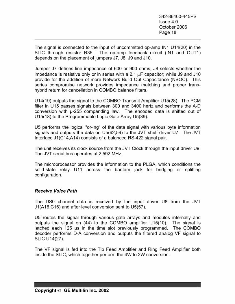
The signal is connected to the input of uncommitted op-amp IN1 U14(20) in the SLIC through resistor R35. The op-amp feedback circuit (IN1 and OUT1) depends on the placement of jumpers J7, J8, J9 and J10. Jumper J7 defines line impedance of 600 or 900 ohms; J8 selects whether the impedance is resistive only or in series with a 2.1 µF capacitor; while J9 and J10 provide for the addition of more Network Build Out Capacitance (NBOC). This series compromise network provides impedance matching and proper trans-hybrid return for cancellation in COMBO balance filters. U14(19) outputs the signal to the COMBO Transmit Amplifier U15(28). The PCM filter in U15 passes signals between 300 and 3400 hertz and performs the A-D conversion with µ-255 companding law. The encoded data is shifted out of U15(18) to the Programmable Logic Gate Array U5(39). U5 performs the logical "or-ing" of the data signal with various byte information signals and outputs the data on U5(62,59) to the JVT shelf driver U7. The JVT Interface J1(C14,A14) consists of a balanced RS-422 signal pair. The unit receives its clock source from the JVT Clock through the input driver U9. The JVT serial bus operates at 2.592 MHz. The microprocessor provides the information to the PLGA, which conditions the solid-state relay U11 across the bantam jack for bridging or splitting configuration. Receive Voice Path The DS0 channel data is received by the input driver U8 from the JVT J1(A16,C16) and after level conversion sent to U5(57). U5 routes the signal through various gate arrays and modules internally and outputs the signal on (44) to the COMBO amplifier U15(10). The signal is latched each 125 µs in the time slot previously programmed. The COMBO decoder performs D-A conversion and outputs the filtered analog VF signal to SLIC U14(27). The VF signal is fed into the Tip Feed Amplifier and Ring Feed Amplifier both inside the SLIC, which together perform the 4W to 2W conversion.
342-86400-445PS Issue 4.0 October 2006 Page 19
Copyright GE Multilin Inc. 2002
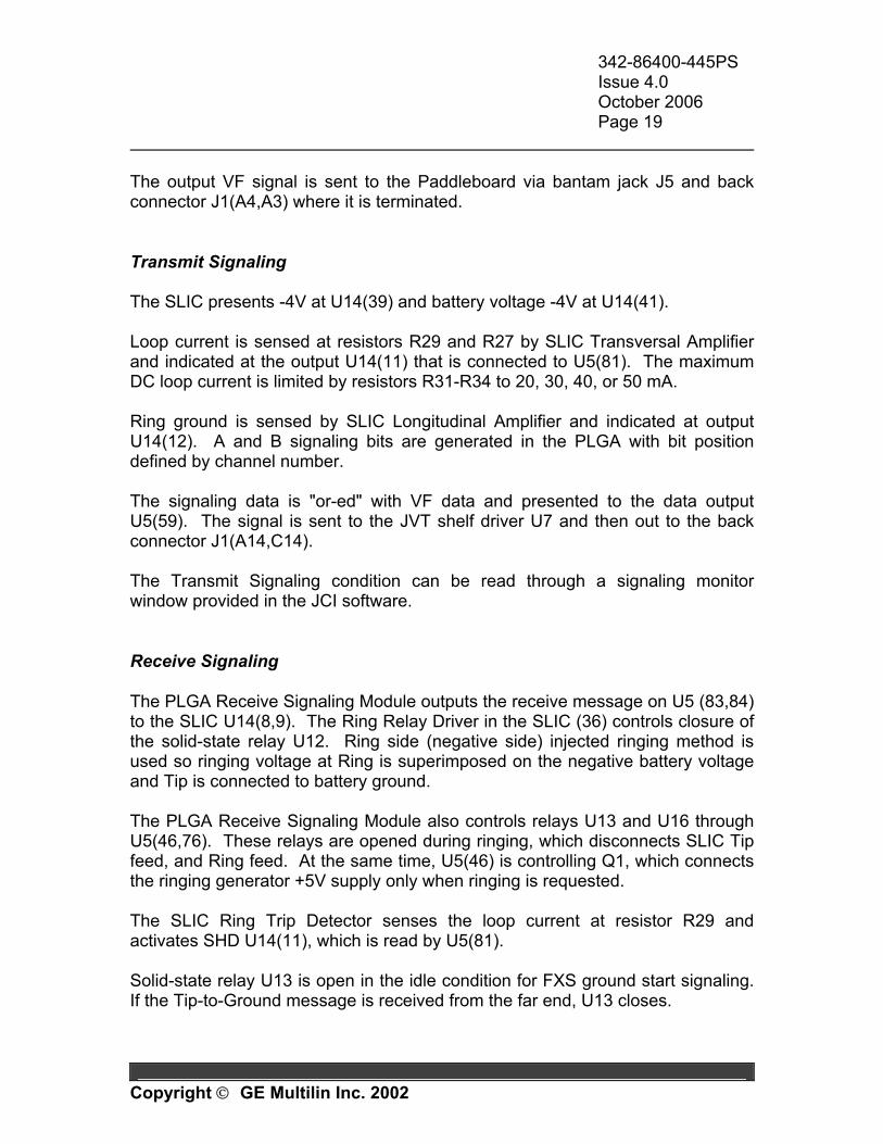
The output VF signal is sent to the Paddleboard via bantam jack J5 and back connector J1(A4,A3) where it is terminated. Transmit Signaling The SLIC presents -4V at U14(39) and battery voltage -4V at U14(41). Loop current is sensed at resistors R29 and R27 by SLIC Transversal Amplifier and indicated at the output U14(11) that is connected to U5(81). The maximum DC loop current is limited by resistors R31-R34 to 20, 30, 40, or 50 mA. Ring ground is sensed by SLIC Longitudinal Amplifier and indicated at output U14(12). A and B signaling bits are generated in the PLGA with bit position defined by channel number. The signaling data is "or-ed" with VF data and presented to the data output U5(59). The signal is sent to the JVT shelf driver U7 and then out to the back connector J1(A14,C14). The Transmit Signaling condition can be read through a signaling monitor window provided in the JCI software. Receive Signaling The PLGA Receive Signaling Module outputs the receive message on U5 (83,84) to the SLIC U14(8,9). The Ring Relay Driver in the SLIC (36) controls closure of the solid-state relay U12. Ring side (negative side) injected ringing method is used so ringing voltage at Ring is superimposed on the negative battery voltage and Tip is connected to battery ground. The PLGA Receive Signaling Module also controls relays U13 and U16 through U5(46,76). These relays are opened during ringing, which disconnects SLIC Tip feed, and Ring feed. At the same time, U5(46) is controlling Q1, which connects the ringing generator +5V supply only when ringing is requested. The SLIC Ring Trip Detector senses the loop current at resistor R29 and activates SHD U14(11), which is read by U5(81). Solid-state relay U13 is open in the idle condition for FXS ground start signaling. If the Tip-to-Ground message is received from the far end, U13 closes.
342-86400-445PS Issue 4.0 October 2006 Page 20
Copyright GE Multilin Inc. 2002
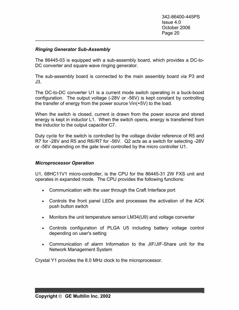
Ringing Generator Sub-Assembly The 86445-03 is equipped with a sub-assembly board, which provides a DC-to-DC converter and square wave ringing generator. The sub-assembly board is connected to the main assembly board via P3 and J3. The DC-to-DC converter U1 is a current mode switch operating in a buck-boost configuration. The output voltage (-28V or -56V) is kept constant by controlling the transfer of energy from the power source Vin(+5V) to the load. When the switch is closed, current is drawn from the power source and stored energy is kept in inductor L1. When the switch opens, energy is transferred from the inductor to the output capacitor C7. Duty cycle for the switch is controlled by the voltage divider reference of R5 and R7 for -28V and R5 and R6//R7 for -56V. Q2 acts as a switch for selecting -28V or -56V depending on the gate level controlled by the micro controller U1. Microprocessor Operation U1, 68HC11V1 micro-controller, is the CPU for the 86445-31 2W FXS unit and operates in expanded mode. The CPU provides the following functions:
• Communication with the user through the Craft Interface port • Controls the front panel LEDs and processes the activation of the ACK
push button switch
• Monitors the unit temperature sensor LM34(U9) and voltage converter
• Controls configuration of PLGA U5 including battery voltage control depending on user's setting
• Communication of alarm Information to the JIF/JIF-Share unit for the
Network Management System Crystal Y1 provides the 8.0 MHz clock to the microprocessor.
342-86400-445PS Issue 4.0 October 2006 Page 21
Copyright GE Multilin Inc. 2002
FEEDBACK
BLOCK DIAGRAM2W FXS/PLAR UNIT
86445-31
ACK
J1
U5XC3042PLGA
2W FXS/PLAR
U2
TEMPSENSOR
5V
TO SHELFPOWER BUS
TO SHELF JVT BUS
NOTE: REFER TO EAS-86445-31 FOR COMPLETE SCHEMATIC.
U4C.I.
39 44
Y1
J1
CLOCKIN
RCVIN
XMTOUT
U15CODEC, FILTER,
HYBRID, BALANCING
18 10
28 2
U1DC/DC
U2RING
GENERATOR
U14 (SLIC)SUBSCRIBER LINE INTERFACE CIRCUIT
32 20 19 27
25
+5V
1 43 41 24 22
25
4
3
2
+5V 4
86445-04 SUB-BOARD
MICRO68HC11
U12
087-86445-03 ASSEMBLY
C15
56U4
U16
A15 C16 A16 C14 A14
U7U8U9
57 59
A2 C2 C4 C7 A3 A4
TIP
RINGRINGINGVOLTAGE
RINGINGCONTROL
BATT-
BATT+
GND
8 7 6 5 4 3 2 1 TB1
GE Multilin
GND
BUSY ALARM
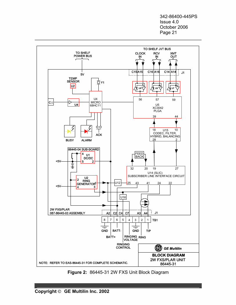
Figure 2: 86445-31 2W FXS Unit Block Diagram

342-86400-445PS Issue 4.0 October 2006 Page 22
Copyright GE Multilin Inc. 2002
1.5 INSTALLATION The following section provides information for installing an 86445-31 FXS unit. The unit is shipped from the factory configured as per the Node Assignment Drawing for the purchased system. All spare units or loose units are shipped with factory default settings in memory.
CAUTION The 86445-31 2W FXS unit has ESDS components and therefore standard static protection precautions should be observed when handling, packing
or shipping the unit. Pre-installation Visually check the unit for damage. Ensure that screws are firmly tightened and in place. Keep the shipping containers and packing materials for future use. If a unit is damaged, file a claim with the shipping agent or the local GE Multilin representative. Set the unit line impedance, network build-out capacitance (NBOC), and current limiting as desired. Refer to the strapping options in Table 1. Factory default settings are 600Ω for line impedance, 0nF for NBOC, and 20mA for current limiting.
Function Jumper Notes NBOC 1 P4-19 to P4-20 Adds 22 nF to network build-out capacitance NBOC 2 P4-17 to P4-18 Adds 47 nF to network build-out capacitance R=900Ω P4-13 to P4-14 Line impedance at 2W VF port R=600Ω P4-15 to P4-16 Line impedance at 2W VF port
Z=R P4-11 to P4-12 Sets impedance to resistive only
Z=R+Xc P4-9 to P4-10 Adds capacitive reactance to impedance (2.15 µF in series)
P4-1 to P4-2 Current limiting is 20 mA P4-3 to P4-4 Current limiting is 30 mA P4-5 to P4-6 Current limiting is 40 mA
Current Limiting
P4-7 to P4-8 Current limiting is 50 mA
Table 1: 86445-31 FXS Unit Strapping Options
342-86400-445PS Issue 4.0 October 2006 Page 23
Copyright GE Multilin Inc. 2002
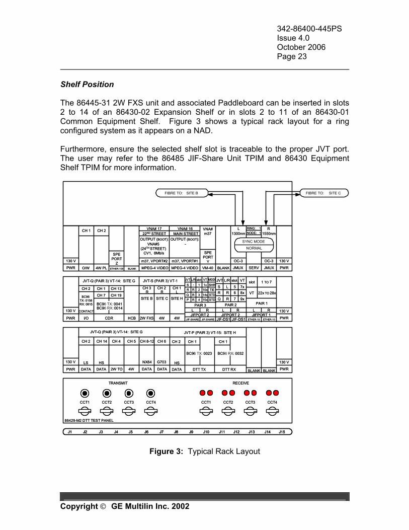
Shelf Position The 86445-31 2W FXS unit and associated Paddleboard can be inserted in slots 2 to 14 of an 86430-02 Expansion Shelf or in slots 2 to 11 of an 86430-01 Common Equipment Shelf. Figure 3 shows a typical rack layout for a ring configured system as it appears on a NAD. Furthermore, ensure the selected shelf slot is traceable to the proper JVT port. The user may refer to the 86485 JIF-Share Unit TPIM and 86430 Equipment Shelf TPIM for more information.
J1 J15J2 J3 J4 J5 J6 J7 J8 J9 J10 J11 J12 J13 J14
CCT1 CCT2 CCT3 CCT4
TRANSMIT RECEIVE
86429-M2 DTT TEST PANEL
CCT1 CCT2 CCT3 CCT4
PWR
130 V
4W2W FXS 4W PWR
130 V
HCBCDR
CONTACT
I/O
S 1x SHR
JIFPORT 2 JIF-SHARE
L R
CH 1
CH 7
CH 13
CH 19
CH 2
JVT-S (PAIR 3) VT-1JVT-Q (PAIR 3) VT-14: SITE G
CH 3 R
CH 1 L
CH 2 R
PAIR 2
JIF-DS1 JIF-DS1
-
JIFPORT 2
Q 7R 9x
R 6R 8xS 5L 7x
JVT L/R VTJVT VT
1
MODEL/R
L R
BC96 TX: 0041
R 2R 10x TIEQ 3R 14x STDP 4R 15x STD
PAIR 3
JIF-SHARE
PWR
130 V
PWR
130 V
2W TO 4W DATA DATA
JVT-Q (PAIR 3) VT-14: SITE G
BC96 RX: 0014
CH 4
BLANK
BC96 TX: 0158RX: 0815
CH 5
NX64
CH 8-12
slotslot
CH 6
G703
PWR
130 V
PWR
130 V
JMUX SERV JMUX
OC-3 OC-3
L R
SITE BFIBRE TO: SITE CFIBRE TO:
O/W VM-40
SPEPORT
Y
1300nmRING: 1 NODE: 1 1550nm
4W PL BLANK
VNA#m37
MPEG-4 VIDEO
VNA# 17
SYNC MODE
NORMAL
CH 1 CH 2
CH 2 CH 14
LS
DATA
HS
DATA
JVT-P (PAIR 3) VT-15: SITE H
DTT RXDTT TX
CH 1 CH 1
BC96 TX: 0023
CH 2
HS
DATA
BC96 RX: 0032
MPEG-4 VIDEO
m37, VPORT#2
OUTPUT (BOOT):VNA#5
(24TH STREET) CV1, 8Mb/s
m37, VPORT#1
VT 22x TO 28x
PAIR 1
1 TO 7
JIFPORT 1L R
ETHER-10
slot
BLANK
ETHER-10
BLANK
SPEPORT
ZETHER-100
SITE B SITE C SITE H
22ND STREETVNA# 16
MAIN STREET
-OUTPUT (BOOT):
J1 J15J2 J3 J4 J5 J6 J7 J8 J9 J10 J11 J12 J13 J14J1 J15J2 J3 J4 J5 J6 J7 J8 J9 J10 J11 J12 J13 J14
CCT1 CCT2 CCT3 CCT4
TRANSMIT RECEIVE
86429-M2 DTT TEST PANEL
CCT1 CCT2 CCT3 CCT4
PWR
130 V
4W2W FXS 4W PWR
130 V
HCBCDR
CONTACT
I/O
S 1x SHR
JIFPORT 2 JIF-SHARE
L R
CH 1
CH 7
CH 13
CH 19
CH 2
JVT-S (PAIR 3) VT-1JVT-Q (PAIR 3) VT-14: SITE G
CH 3 R
CH 1 L
CH 2 R
PAIR 2
JIF-DS1 JIF-DS1
-
JIFPORT 2
Q 7R 9x
R 6R 8xS 5L 7x
JVT L/R VTJVT VT
1
MODEL/R
L R
BC96 TX: 0041
R 2R 10x TIEQ 3R 14x STDP 4R 15x STD
PAIR 3
JIF-SHARE
PWR
130 V
PWR
130 V
2W TO 4W DATA DATA
JVT-Q (PAIR 3) VT-14: SITE G
BC96 RX: 0014
CH 4
BLANK
BC96 TX: 0158RX: 0815
CH 5
NX64
CH 8-12
slotslot
CH 6
G703
PWR
130 V
PWR
130 V
JMUX SERV JMUX
OC-3 OC-3
L R
SITE BFIBRE TO: SITE CFIBRE TO:
O/W VM-40
SPEPORT
Y
1300nmRING: 1 NODE: 1 1550nm
4W PL BLANK
VNA#m37
MPEG-4 VIDEO
VNA# 17
SYNC MODE
NORMAL
CH 1 CH 2
CH 2 CH 14
LS
DATA
HS
DATA
JVT-P (PAIR 3) VT-15: SITE H
DTT RXDTT TX
CH 1 CH 1
BC96 TX: 0023
CH 2
HS
DATA
BC96 RX: 0032
MPEG-4 VIDEO
m37, VPORT#2
OUTPUT (BOOT):VNA#5
(24TH STREET) CV1, 8Mb/s
m37, VPORT#1
VT 22x TO 28x
PAIR 1
1 TO 7
JIFPORT 1L R
ETHER-10
slot
BLANK
ETHER-10
BLANK
SPEPORT
ZETHER-100
SITE B SITE C SITE H
22ND STREETVNA# 16
MAIN STREET
-OUTPUT (BOOT):
Figure 3: Typical Rack Layout
342-86400-445PS Issue 4.0 October 2006 Page 24
Copyright GE Multilin Inc. 2002
Power Requirements Power for the 86445-31 2W FXS unit is supplied from the shelf, therefore no external power supply is required. If it is required to provide external ringing generator and station battery externally, they can be supplied through Paddleboard connections only after removal of the 028-86445-04 sub-board. The unit can be inserted and removed from the shelf with shelf power applied. Inserting the Unit in the Shelf
WARNING For systems already in service, inserting a 2W FXS unit without the ACK
button pressed may cause traffic disruption in a DS0 channel on the same JVT.
WARNING
Do not use the red tab to force the unit into the shelf as this could result in damage to the red tab.
1. Set the unit strapping options as desired (refer to Table 1). 2. Insert the unit to the point of resistance. 3. With the “ACK” button pressed, gently seat the unit into the shelf by pressing
the front panel. (Ensure the red tab is not preventing the unit from insertion.)
Note: The 2W FXS unit inserted with ACK button pressed is in the “Sleep mode” and the DS0 channel assignment on the unit is disabled at that point.
4. Use VistaNET (local connection) or JCI to program the unit in accordance to the NAD for the given node. Refer to the Configuration Section of this manual.
Removing the Unit from the Shelf 1. Use the red tab to remove the unit from the shelf. Note: The Copy-and-Paste available in VistaNET (local connection only) can be used to copy the configuration from the unit to be removed to the replacement unit. For more information refer to the Configuration section.
342-86400-445PS Issue 4.0 October 2006 Page 25
Copyright GE Multilin Inc. 2002
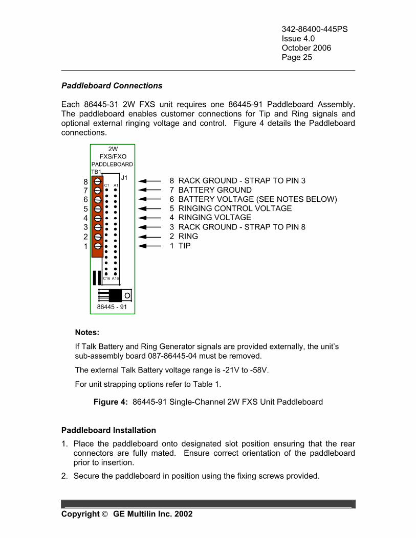
Paddleboard Connections Each 86445-31 2W FXS unit requires one 86445-91 Paddleboard Assembly. The paddleboard enables customer connections for Tip and Ring signals and optional external ringing voltage and control. Figure 4 details the Paddleboard connections.
TB1J1
2WFXS/FXO
PADDLEBOARD
C1 A1
86445 - 91
8 7 6 5 4 3 2 1
8 RACK GROUND - STRAP TO PIN 37 BATTERY GROUND 6 BATTERY VOLTAGE (SEE NOTES BELOW) 5 RINGING CONTROL VOLTAGE 4 RINGING VOLTAGE 3 RACK GROUND - STRAP TO PIN 8 2 RING 1 TIP
C16 A16
Notes:
If Talk Battery and Ring Generator signals are provided externally, the unit’s sub-assembly board 087-86445-04 must be removed.
The external Talk Battery voltage range is -21V to -58V.
For unit strapping options refer to Table 1.
Figure 4: 86445-91 Single-Channel 2W FXS Unit Paddleboard Paddleboard Installation 1. Place the paddleboard onto designated slot position ensuring that the rear
connectors are fully mated. Ensure correct orientation of the paddleboard prior to insertion.
2. Secure the paddleboard in position using the fixing screws provided.
342-86400-445PS Issue 4.0 October 2006 Page 26
Copyright GE Multilin Inc. 2002
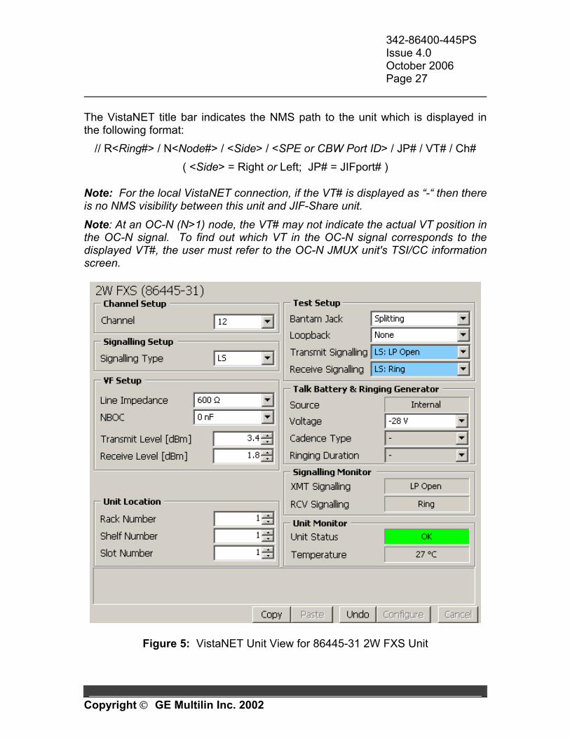
1.6 CONFIGURATION To configure the 86445-31 2W FXS unit locally, connect a PC running VNI (VistaNET Network Interface) or VLA (VistaNET Local Access) program to the CI jack at the front of the unit through a COM port. Alternatively, a legacy JCI (JungleMUX Craft Interface) software may be used. An 84910-05 RJ-11 cable and an 84910-06 (9-pin adapter) or 84910-07 (25-pin adapter) are required. The unit’s programmable parameters along with the unit status information are displayed automatically once the communication to the unit is established. The unit can also be configured remotely through the network management system using VistaNET (if VNI is used) or legacy JNCI (JungleMUX Network Craft Interface); however, the channel assignment field must be configured locally prior to establishing the NMS connection to the unit. The capabilities and features of VistaNET and JNCI network management software packages are described in respective User’s Manuals. The units that are shipped as part of a purchased JungleMUX node have their programmable fields set as per the Node Assignment Drawing (NAD) for the node. Below is a description of the VistaNET Unit View for the 86445-31 2W FXS Unit. Note that the same layout is used in both local and network (remote) communication modes. Explanations for all the fields that appear in this view along with their function are included. The explanation of JCI screen for the 86445-31 2W FXS unit is provided in Appendix B. VISTANET UNIT VIEW INFORMATION General Information When a VistaNET connection (local or network) to an 86445-31 2W FXS unit is established, the unit view is displayed (Figure 5). It comprises various configurable and read-only fields. Located below them are the context-sensitive help text-box and action buttons.
342-86400-445PS Issue 4.0 October 2006 Page 27
Copyright GE Multilin Inc. 2002
The VistaNET title bar indicates the NMS path to the unit which is displayed in the following format:
// R<Ring#> / N<Node#> / <Side> / <SPE or CBW Port ID> / JP# / VT# / Ch# ( <Side> = Right or Left; JP# = JIFport# )
Note: For the local VistaNET connection, if the VT# is displayed as “-“ then there is no NMS visibility between this unit and JIF-Share unit. Note: At an OC-N (N>1) node, the VT# may not indicate the actual VT position in the OC-N signal. To find out which VT in the OC-N signal corresponds to the displayed VT#, the user must refer to the OC-N JMUX unit's TSI/CC information screen.
Figure 5: VistaNET Unit View for 86445-31 2W FXS Unit
342-86400-445PS Issue 4.0 October 2006 Page 28
Copyright GE Multilin Inc. 2002
Context-Sensitive Help
When the mouse-pointer is positioned over a specific field label, the text-box located at the bottom of this view will provide general information on the field. Also, for some fields, when the mouse-pointer is positioned over the field itself, more info is provided on that specific reading/selection.
Configure button
Writes the changes made in configurable fields to the unit.
Note: Any changes made in the configurable fields will not take effect until after the Configure button is pressed. Multiple fields may be configured simultaneously.
Undo button Undoes the configuration changes written to the unit when the Configure button was pressed last time. It is possible to keep undoing previously performed configuration changes until the Undo button becomes disabled.
Note: Upon moving to a different unit, the VistaNET will forget the information on the last applied configuration changes. Therefore, the Undo action is possible only for the same unit to which the Configuration changes have been applied.
Cancel button Cancels the changes made in configurable fields and refreshes them with the previously displayed values.
Note: Only the changes made after the last Configure (or Undo) action can be cancelled.
Copy and Paste buttons These fields allow the user to copy the unit configuration settings to another unit of the same type. Click on Copy at the source unit, move the cable to the destination unit, and click on Paste. All the fields whose configurations are about to be changed are highlighted. Click on the Configure button to write the changes to the destination unit.
Note: The source unit configuration settings are stored in the “clipboard” and may be applied to unlimited number of destination units of the same type. Note: The user is allowed to modify the selections prior to pressing the Configure button.
342-86400-445PS Issue 4.0 October 2006 Page 29
Copyright GE Multilin Inc. 2002
Note: The user may opt not to apply the changes to the destination unit in which case the Cancel button shall be selected after the Paste action.
Field Descriptions All fields (programmable and read-only) are grouped in frames based on their function. Channel Setup Channel
Allows DS0 channel assignment to the unit. Channel number is selectable from 1 to 24. A ‘-‘ (default selection) indicates that a channel has not been assigned. Each channel occupies its own DS0 (64 kb/s) time slot on the JVT. Ensure that the channel assigned on this unit is not assigned on any other DS0 level unit on the same JVT. The corresponding far-end unit must be given the same channel assignment.
Signalling Setup Signalling Type
May be set to Loop Start (LS), Ground Start (GS) or Private Line Automatic Ringdown (PLAR). The far-end unit interface must be set for the same signaling type.
Note: Although the 86445-31 2W FXS unit is normally used with either 86445-41 2W FXO unit (for LS and GS applications) or 86445-3X 2W FXS unit (for PLAR application) at the far end, it can also be used with an 86444 4W VF unit when no signaling is required. This may be utilized for VF channel testing.
VF Setup Line Impedance
May be set to either 600 Ω or 900 Ω in series with or without 2.15 µF of line capacitance. This impedance must also be hardware strapped on the main assembly board.
Note: The selection made in this field must match the respective strapping selection made on the unit's main assembly board.
342-86400-445PS Issue 4.0 October 2006 Page 30
Copyright GE Multilin Inc. 2002
Note: It is important to match the actual line impedance with the 2W FXS unit's input impedance to maximize the amount of power to be transferred from the telephone to the line. Impedance mismatches create side tones which in the worst case are perceived as echoes. The addition of 2.15 µF adds capacitive reactance to the line that may reduce noise and distortion.
NBOC
Selectable to 0, 22, 47 or 69 nF. This may be used for additional line capacitance compensation. NBOC must also be hardware strapped on the main assembly board.
Note: The selection made in this field must match the respective strapping selection made on the unit's main assembly board. Note: Network build-out capacitance is added to provide additional line balancing. Generally, no additional NBOC is required for lines shorter than 2000 ft (600 m).
Transmit Level [dBm]
Software selectable from -14.0 to +6.0 dBm in 0.1 dB increments. Default is 0 dBm.
Note: The Line Impedance parameter shall be set before Transmit Level because any subsequent changes to the Line Impedance setting may also alter the Transmit Level setting.
Receive Level [dBm]
Software selectable from -15.0 to +5.0 dBm in 0.1 dB increments. Default is -2 dBm.
Note: The Line Impedance parameter shall be set before Receive Level because any subsequent changes to the Line Impedance setting may also alter the Receive Level setting.
Unit Location Rack Number (use is optional)
Identifies the rack or cabinet (1 to 64) in which the unit is located. This information may be utilized on the NMS (Network Management System).
Shelf Number (use is optional)
Identifies the shelf (1 to 64) in which the unit is located. This information may be utilized on the NMS.
342-86400-445PS Issue 4.0 October 2006 Page 31
Copyright GE Multilin Inc. 2002
Slot Number (use is optional)
Identifies the slot position within the shelf (1 to 15) in which the unit is located. This information may be utilized on the NMS.
Test Setup Bantam Jack
May be set for Bridging or Splitting (default). Bridging mode allows for monitoring of the circuit via bantam jacks on the unit face plate. Splitting mode disconnects the drop side of the circuit (upon insertion of test jack) and allows tones to be injected and measured for end-to-end or loopback testing.
Loopback
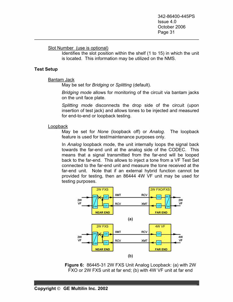
May be set for None (loopback off) or Analog. The loopback feature is used for test/maintenance purposes only. In Analog loopback mode, the unit internally loops the signal back towards the far-end unit at the analog side of the CODEC. This means that a signal transmitted from the far-end will be looped back to the far-end. This allows to inject a tone from a VF Test Set connected to the far-end unit and measure the tone received at the far-end unit. Note that if an external hybrid function cannot be provided for testing, then an 86444 4W VF unit may be used for testing purposes.
RCV
XMT
2W FXS 2W FXO/FXS
2W
4W
XMT
RCV
4W
2W
2WVF
2WVF
NEAR END FAR END
A/D
D/A
D/A
A/D
(a)
RCV
XMT
2W FXS 4W VF
2W
4W
XMT
RCV2WVF
4WVF
NEAR END FAR END
A/D
D/A
D/A
A/D
(b)
RCV
XMT
2W FXS 2W FXO/FXS
2W
4W
2W
4W
XMT
RCV
4W
2W
4W
2W
2WVF
2WVF
NEAR END FAR END
A/D
D/A
D/A
A/D
(a)
RCV
XMT
2W FXS 4W VF
2W
4W
2W
4W
XMT
RCV2WVF
4WVF
NEAR END FAR END
A/D
D/A
D/A
A/D
(b) Figure 6: 86445-31 2W FXS Unit Analog Loopback: (a) with 2W
FXO or 2W FXS unit at far end; (b) with 4W VF unit at far end
342-86400-445PS Issue 4.0 October 2006 Page 32
Copyright GE Multilin Inc. 2002
Note: This field must be set to 'None' when not being used for test or maintenance purposes.
Transmit Signalling
Allows the user to set a specific signaling condition that will be sent to the far-end unit and is used for test/maintenance purposes only. The signaling options available depend on the Signalling Type selected (see Signalling Setup window).
Note: This field must be set to ‘-‘ when not being used for test or maintenance purposes. Note: When testing from near end to far end, the far-end unit Receive Signalling should be configured to '-'. Note: The unit's yellow (BUSY) LED illuminates only if an OFF-HOOK condition is initiated from an external source (i.e. signaling test set or telephone). Note: The signaling information is mapped into two bits of the PSFR byte (part of VT1.5 frame). There are four possible transmit signaling combinations that can be addressed by these bits: 00, 01, 10, and 11 and some of them are not used. When an Invalid signaling condition (combination of the two bits) is selected, the unit will send the selected combination even though it does not apply to any valid signaling condition for the Signalling Type chosen.
Receive Signalling Allows the user to set a specific signaling condition that will be sent to the local drop equipment and is used for test/maintenance purposes only. The options available depend on the Signalling Type selected (see Signalling Setup window).
Note: This field must be set to ‘-‘ when not being used for test or maintenance purposes.
Talk Battery and Ringing Generator Source
Displays "Internal". Voltage
Selectable for -28 or -56 V. This is the talk battery voltage that this unit's sub-board will provide to the line (if installed). Note: On units configured for 600Ω resistive only, it is recommended that -56 VDC not be used.
342-86400-445PS Issue 4.0 October 2006 Page 33
Copyright GE Multilin Inc. 2002
Cadence Type
Sets the type of ringing produced when in PLAR mode. May be set to North American, European or Steady.
Note: This field is active only if PLAR is selected in the Signalling Type field (see Signalling Setup window) and the unit's Micro code is version 2.5 or later.
Ringing Duration
Sets the ringing duration when in PLAR mode. May be set to 10 sec, 20 sec, 60 sec and Indefinite.
Note: This field is active only if PLAR is selected in the Signalling Type field (see Signalling Setup window) and the unit's Micro code is version 2.5 or later. Note: In the Loop Start (LS) and Ground Start (GS) signaling modes the ringing duration is not limited.
Signalling Monitor XMT Signalling
Shows current signaling status sent towards the far-end unit.
Note: When an Invalid signaling condition (i.e. combination of the two signaling bits) is selected in the Transmit Signalling field (see Test Setup frame), the unit will send the selected combination even though it does not apply to any valid signaling condition for the Signalling Type chosen.
Receive Signalling
Shows current signaling status received from the far-end unit (unless overridden by the locally forced RCV Signalling test condition in which case the forced condition is displayed).
Unit Monitor Unit Status
Displays the current status of the unit. The possible readings are: Temperature (unit temperature exceeds 93ºC) and OK.
Temperature Displays the current temperature of the unit in ºC. An alarm is raised in the Unit Status field if this reading exceeds 93ºC.
342-86400-445PS Issue 4.0 October 2006 Page 34
Copyright GE Multilin Inc. 2002
1.7 MAINTENANCE and TROUBLESHOOTING Context-Sensitive Help When the mouse-pointer is positioned over a specific field label in the VistaNET Unit View, the text-box located at the bottom of the view will provide general information on the field. Also, for some fields, when the mouse-pointer is positioned over the field itself, more info is provided on that specific reading/selection. This is a useful tool for explaining the capabilities and options of both programmable fields and read-only fields of the unit. Note: When the legacy JCI software is used, the help screen can be invoked by selecting “F1” key. Alignment The 86445-31 2W FXS unit must be correctly configured as per the Node Assignment Drawing. All software adjustable fields are detailed in the Configuration section of this manual. The user must ensure that all external connections to the paddleboard are correct. Bantam Jack The front-panel bantam jack provides access to the 2W VF signal. Through the software, it can be configured for splitting or bridging. The bridging access can be used for monitoring the analog VF signal present at the paddleboard connections. The splitting access disconnects the paddleboard connections so that the bantam jack signal can be used for testing purposes. Signaling Tests Unit's built-in signaling test features allow for sending a specific, user-selectable signaling condition to the far-end unit and/or to the local drop equipment. Refer to Transmit Signalling and Receive Signalling fields in the Configuration section for more information.
342-86400-445PS Issue 4.0 October 2006 Page 35
Copyright GE Multilin Inc. 2002
Loopback Commands Analog loopback can be performed for the purpose of testing and maintenance. This lopback is explained in the previous section under Test Setup. Troubleshooting If an 86445-31 2W FXS unit is suspected of being defective, substitute it for a known-good 86445-311 unit and if the unit functions properly return the original to GE Multilin for repair or replacement. Ensure that the substitute unit is configured correctly. The following table is intended to provide the user with possible solutions to problems that may be encountered during normal unit operation.
1 The 86445-32 unit may also be used as a replacement unit in which case the paddleboard must be replaced as well (86445-32 unit requires 86445-92 paddleboard).
342-86400-445PS Issue 4.0 October 2006 Page 36
Copyright GE Multilin Inc. 2002
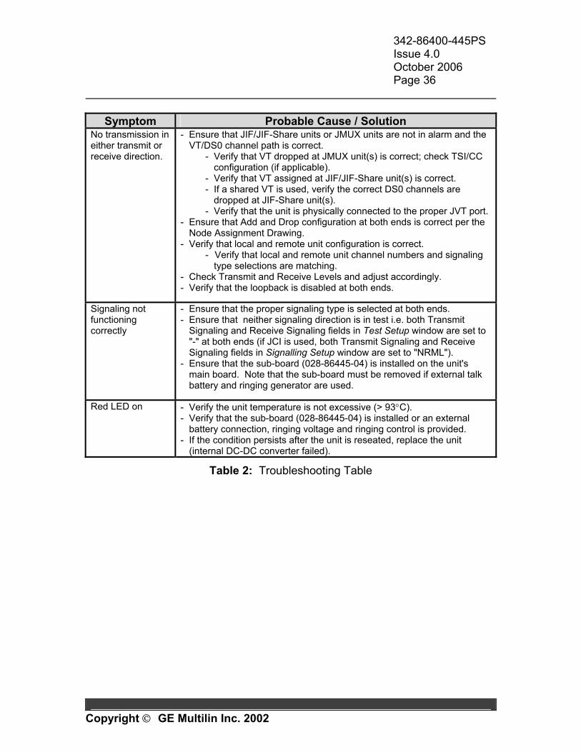
Symptom Probable Cause / Solution
No transmission in either transmit or receive direction.
- Ensure that JIF/JIF-Share units or JMUX units are not in alarm and the VT/DS0 channel path is correct.
- Verify that VT dropped at JMUX unit(s) is correct; check TSI/CC configuration (if applicable).
- Verify that VT assigned at JIF/JIF-Share unit(s) is correct. - If a shared VT is used, verify the correct DS0 channels are
dropped at JIF-Share unit(s). - Verify that the unit is physically connected to the proper JVT port.
- Ensure that Add and Drop configuration at both ends is correct per the Node Assignment Drawing.
- Verify that local and remote unit configuration is correct. - Verify that local and remote unit channel numbers and signaling
type selections are matching. - Check Transmit and Receive Levels and adjust accordingly. - Verify that the loopback is disabled at both ends.
Signaling not functioning correctly
- Ensure that the proper signaling type is selected at both ends. - Ensure that neither signaling direction is in test i.e. both Transmit
Signaling and Receive Signaling fields in Test Setup window are set to "-" at both ends (if JCI is used, both Transmit Signaling and Receive Signaling fields in Signalling Setup window are set to "NRML").
- Ensure that the sub-board (028-86445-04) is installed on the unit's main board. Note that the sub-board must be removed if external talk battery and ringing generator are used.
Red LED on - Verify the unit temperature is not excessive (> 93°C).
- Verify that the sub-board (028-86445-04) is installed or an external battery connection, ringing voltage and ringing control is provided.
- If the condition persists after the unit is reseated, replace the unit (internal DC-DC converter failed).
Table 2: Troubleshooting Table
342-86400-445PS Issue 4.0 October 2006 Page 37
Copyright GE Multilin Inc. 2002
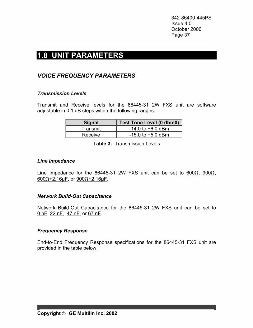
1.8 UNIT PARAMETERS VOICE FREQUENCY PARAMETERS Transmission Levels Transmit and Receive levels for the 86445-31 2W FXS unit are software adjustable in 0.1 dB steps within the following ranges:
Signal Test Tone Level (0 dbm0) Transmit -14.0 to +6.0 dBm Receive -15.0 to +5.0 dBm
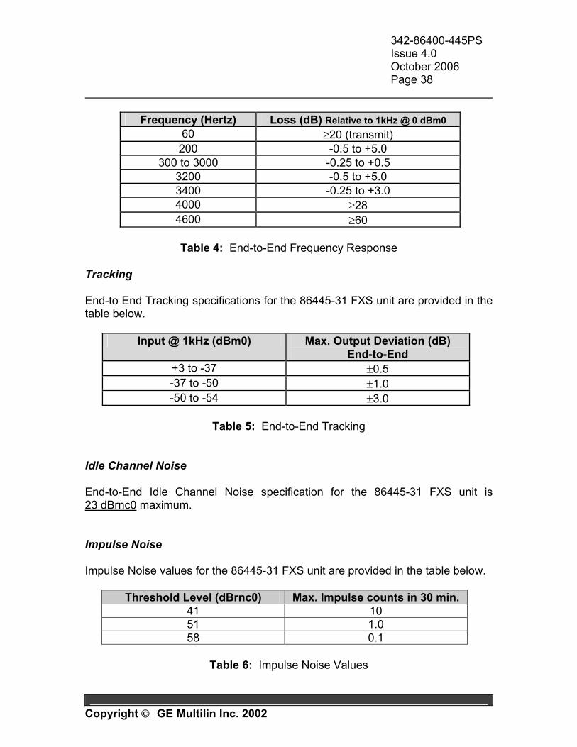
Table 3: Transmission Levels Line Impedance Line Impedance for the 86445-31 2W FXS unit can be set to 600Ω, 900Ω, 600Ω+2.16µF, or 900Ω+2.16µF. Network Build-Out Capacitance Network Build-Out Capacitance for the 86445-31 2W FXS unit can be set to 0 nF, 22 nF, 47 nF, or 67 nF. Frequency Response End-to-End Frequency Response specifications for the 86445-31 FXS unit are provided in the table below.
342-86400-445PS Issue 4.0 October 2006 Page 38
Copyright GE Multilin Inc. 2002
Frequency (Hertz) Loss (dB) Relative to 1kHz @ 0 dBm0
60 ≥20 (transmit) 200 -0.5 to +5.0
300 to 3000 -0.25 to +0.5 3200 -0.5 to +5.0 3400 -0.25 to +3.0 4000 ≥28 4600 ≥60
Table 4: End-to-End Frequency Response
Tracking End-to End Tracking specifications for the 86445-31 FXS unit are provided in the table below.
Input @ 1kHz (dBm0) Max. Output Deviation (dB) End-to-End
+3 to -37 ±0.5 -37 to -50 ±1.0 -50 to -54 ±3.0
Table 5: End-to-End Tracking
Idle Channel Noise End-to-End Idle Channel Noise specification for the 86445-31 FXS unit is 23 dBrnc0 maximum. Impulse Noise Impulse Noise values for the 86445-31 FXS unit are provided in the table below.
Threshold Level (dBrnc0) Max. Impulse counts in 30 min. 41 10 51 1.0 58 0.1
Table 6: Impulse Noise Values
342-86400-445PS Issue 4.0 October 2006 Page 39
Copyright GE Multilin Inc. 2002
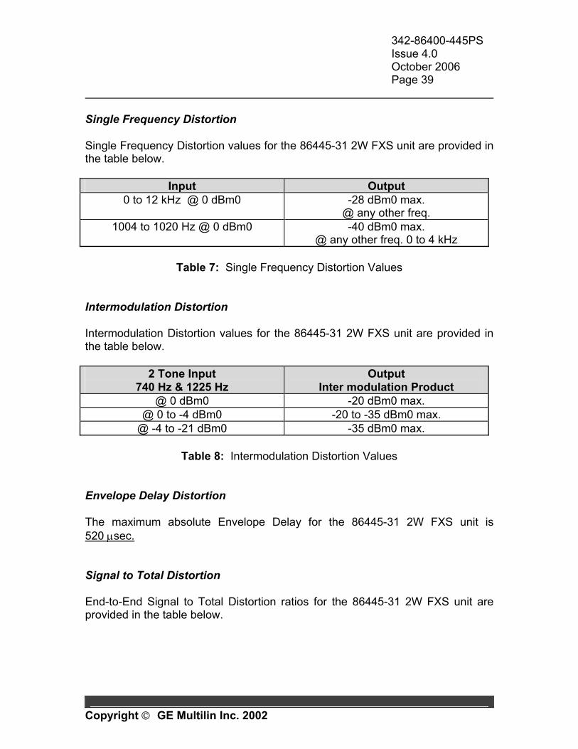
Single Frequency Distortion Single Frequency Distortion values for the 86445-31 2W FXS unit are provided in the table below.
Input Output 0 to 12 kHz @ 0 dBm0 -28 dBm0 max.
@ any other freq. 1004 to 1020 Hz @ 0 dBm0 -40 dBm0 max.
@ any other freq. 0 to 4 kHz
Table 7: Single Frequency Distortion Values Intermodulation Distortion Intermodulation Distortion values for the 86445-31 2W FXS unit are provided in the table below.
2 Tone Input 740 Hz & 1225 Hz
Output Inter modulation Product
@ 0 dBm0 -20 dBm0 max. @ 0 to -4 dBm0 -20 to -35 dBm0 max.
@ -4 to -21 dBm0 -35 dBm0 max.
Table 8: Intermodulation Distortion Values Envelope Delay Distortion The maximum absolute Envelope Delay for the 86445-31 2W FXS unit is 520 µsec. Signal to Total Distortion End-to-End Signal to Total Distortion ratios for the 86445-31 2W FXS unit are provided in the table below.
342-86400-445PS Issue 4.0 October 2006 Page 40
Copyright GE Multilin Inc. 2002
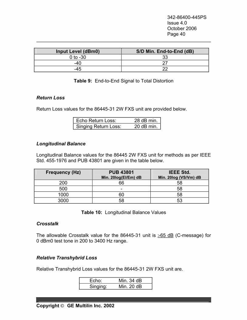
Input Level (dBm0) S/D Min. End-to-End (dB)
0 to -30 33 -40 27 -45 22
Table 9: End-to-End Signal to Total Distortion
Return Loss Return Loss values for the 86445-31 2W FXS unit are provided below.
Echo Return Loss: 28 dB min. Singing Return Loss: 20 dB min.
Longitudinal Balance Longitudinal Balance values for the 86445 2W FXS unit for methods as per IEEE Std. 455-1976 and PUB 43801 are given in the table below.
Frequency (Hz) PUB 43801 Min. 20log(El/Em) dB
IEEE Std. Min. 20log (VS/Vm) dB
200 66 58 500 - 58 1000 60 58 3000 58 53
Table 10: Longitudinal Balance Values
Crosstalk The allowable Crosstalk value for the 86445-31 unit is >65 dB (C-message) for 0 dBm0 test tone in 200 to 3400 Hz range. Relative Transhybrid Loss Relative Transhybrid Loss values for the 86445-31 2W FXS unit are.
Echo: Min. 34 dB Singing: Min. 20 dB
342-86400-445PS Issue 4.0 October 2006 Page 41
Copyright GE Multilin Inc. 2002
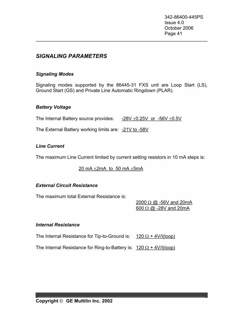
SIGNALING PARAMETERS Signaling Modes Signaling modes supported by the 86445-31 FXS unit are Loop Start (LS), Ground Start (GS) and Private Line Automatic Ringdown (PLAR). Battery Voltage The Internal Battery source provides: -28V ±0.25V or -56V ±0.5V The External Battery working limits are: -21V to -58V Line Current The maximum Line Current limited by current setting resistors in 10 mA steps is: 20 mA ±2mA to 50 mA ±5mA External Circuit Resistance The maximum total External Resistance is: 2000 Ω @ -56V and 20mA 600 Ω @ -28V and 20mA Internal Resistance The Internal Resistance for Tip-to-Ground is: 120 Ω + 4V/I(loop) The Internal Resistance for Ring-to-Battery is: 120 Ω + 4V/I(loop)
342-86400-445PS Issue 4.0 October 2006 Page 42
Copyright GE Multilin Inc. 2002
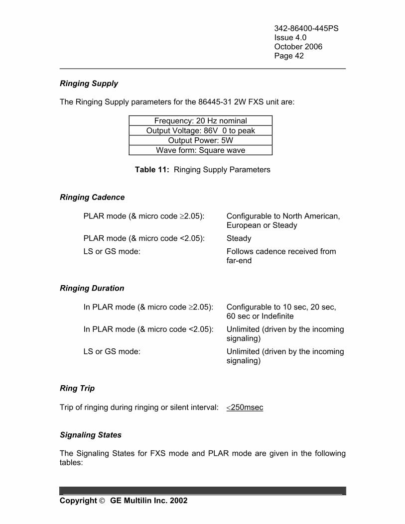
Ringing Supply The Ringing Supply parameters for the 86445-31 2W FXS unit are:
Frequency: 20 Hz nominal Output Voltage: 86V 0 to peak
Output Power: 5W Wave form: Square wave
Table 11: Ringing Supply Parameters
Ringing Cadence
PLAR mode (& micro code ≥2.05): Configurable to North American, European or Steady
PLAR mode (& micro code <2.05): Steady LS or GS mode: Follows cadence received from
far-end Ringing Duration
In PLAR mode (& micro code ≥2.05): Configurable to 10 sec, 20 sec, 60 sec or Indefinite
In PLAR mode (& micro code <2.05): Unlimited (driven by the incoming signaling)
LS or GS mode: Unlimited (driven by the incoming signaling)
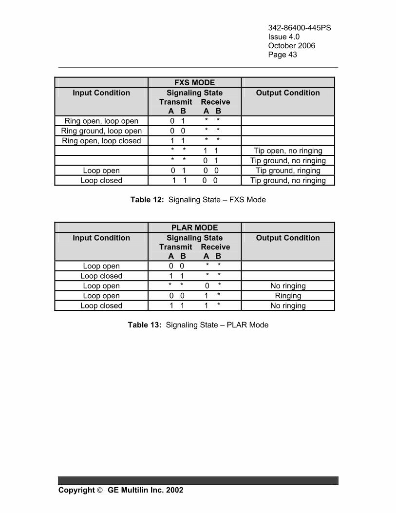
Ring Trip Trip of ringing during ringing or silent interval: <250msec Signaling States The Signaling States for FXS mode and PLAR mode are given in the following tables:
342-86400-445PS Issue 4.0 October 2006 Page 43
Copyright GE Multilin Inc. 2002
FXS MODE
Input Condition Signaling State Transmit Receive
A B A B
Output Condition
Ring open, loop open 0 1 * * Ring ground, loop open 0 0 * * Ring open, loop closed 1 1 * *
* * 1 1 Tip open, no ringing * * 0 1 Tip ground, no ringing
Loop open 0 1 0 0 Tip ground, ringing Loop closed 1 1 0 0 Tip ground, no ringing
Table 12: Signaling State – FXS Mode
PLAR MODE Input Condition Signaling State
Transmit Receive A B A B
Output Condition
Loop open 0 0 * * Loop closed 1 1 * * Loop open * * 0 * No ringing Loop open 0 0 1 * Ringing
Loop closed 1 1 1 * No ringing
Table 13: Signaling State – PLAR Mode

342-86400-445PS Issue 4.0 October 2006 Page 44
Copyright GE Multilin Inc. 2002
1.9 SPECIFICATIONS Physical The 2W FXS unit is housed in a standard JungleMUX shelf mechanics and occupies a single shelf slot with the following dimensions: 1) Height: 89 mm (3.5 inches) 2) Width: 29 mm (1.135 inches) 3) Depth: 203 mm (8 inches) 4) Weight: 237 grams (8 oz) Connector Type: Paddleboard Terminal Block Connector Electrical The input power requirements for the 2W FXS unit are: 1) Voltage: 5.2 VDC ±5% 2) Current: 100 mA @ +5 VDC (Idle) 3) Power Consumption: 1.0W (Busy); 0.5W (Idle) This voltage is supplied from the 86430 Equipment Shelf. Environmental 1) Temperature: Guaranteed Performance: -20 to +60°C (-4 to +140°F) Storage: -40 to +70°C (-40 to +158°F) 2) Relative Humidity: 5 to 95% @ 40ºC, non-condensing, 10 days 3) Shipping Altitude: 15,000 meters (50,000 feet)
342-86400-445PS Issue 4.0 October 2006 Page 45
Copyright GE Multilin Inc. 2002
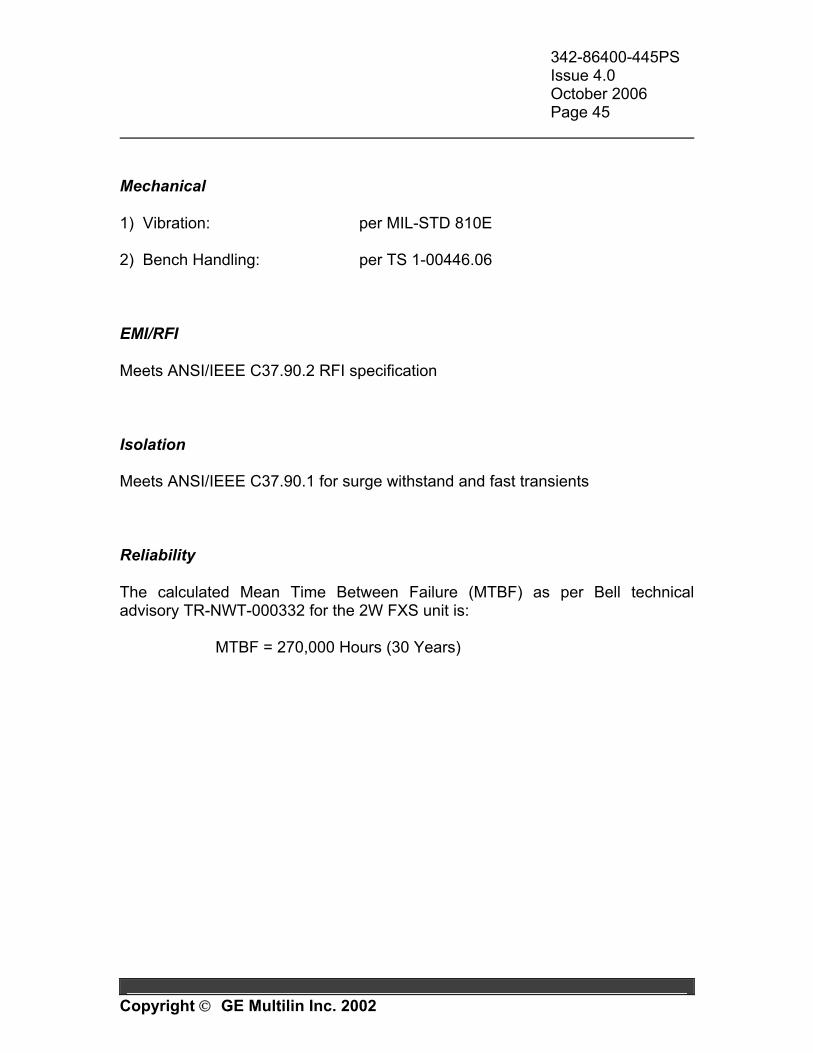
Mechanical 1) Vibration: per MIL-STD 810E 2) Bench Handling: per TS 1-00446.06 EMI/RFI Meets ANSI/IEEE C37.90.2 RFI specification Isolation Meets ANSI/IEEE C37.90.1 for surge withstand and fast transients Reliability The calculated Mean Time Between Failure (MTBF) as per Bell technical advisory TR-NWT-000332 for the 2W FXS unit is: MTBF = 270,000 Hours (30 Years)
342-86400-445PS Issue 4.0 October 2006 Page 46
Copyright GE Multilin Inc. 2002
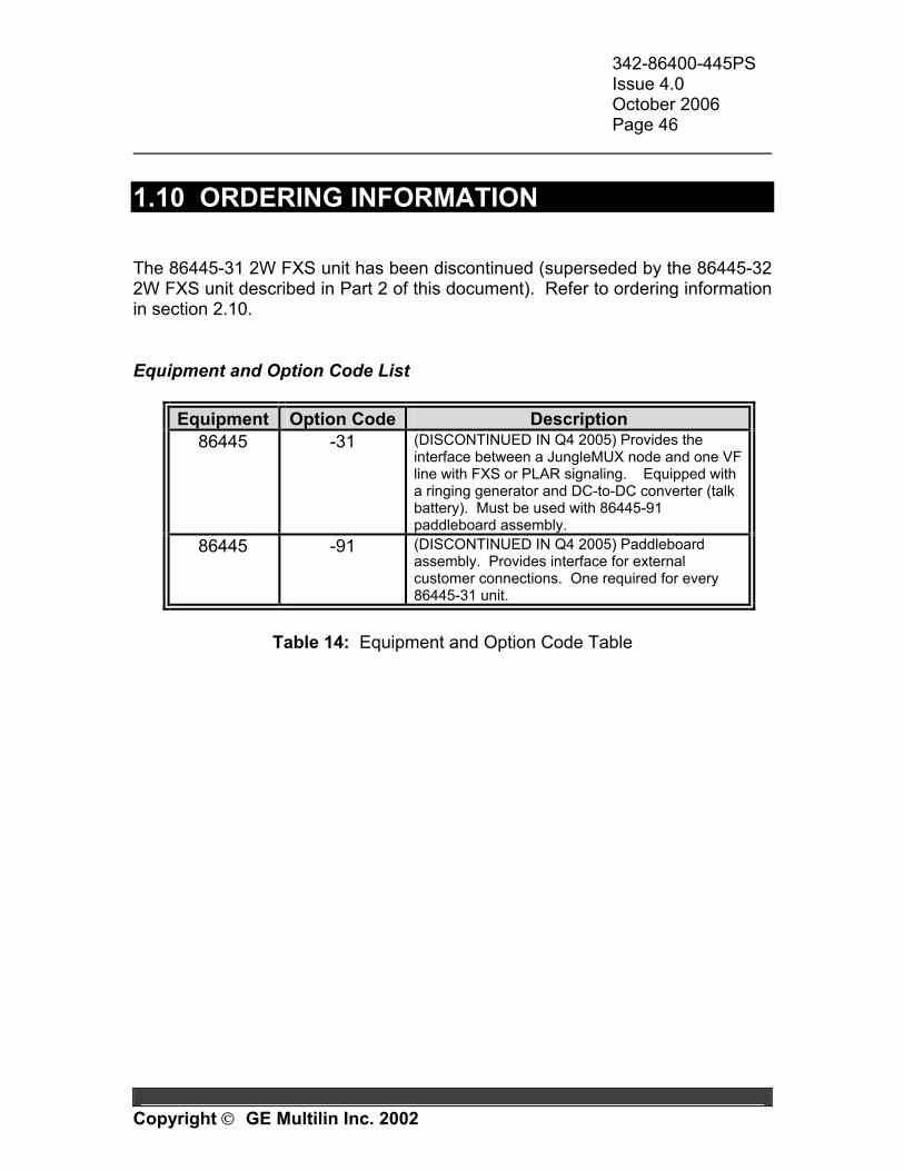
1.10 ORDERING INFORMATION The 86445-31 2W FXS unit has been discontinued (superseded by the 86445-32 2W FXS unit described in Part 2 of this document). Refer to ordering information in section 2.10. Equipment and Option Code List
Equipment Option Code Description 86445 -31
(DISCONTINUED IN Q4 2005) Provides the interface between a JungleMUX node and one VF line with FXS or PLAR signaling. Equipped with a ringing generator and DC-to-DC converter (talk battery). Must be used with 86445-91 paddleboard assembly.
86445 -91 (DISCONTINUED IN Q4 2005) Paddleboard assembly. Provides interface for external customer connections. One required for every 86445-31 unit.
Table 14: Equipment and Option Code Table

342-86400-445PS Issue 4.0 October 2006 Page 47
Copyright GE Multilin Inc. 2002
Part 2
86445-32 2W FXS/PLAR Unit
(Dual-Channel)
342-86400-445PS Issue 4.0 October 2006 Page 48
Copyright GE Multilin Inc. 2002
2.1 INTRODUCTION The 86445-32 2W FXS (dual-channel) unit is one of the family of units in the GE Multilin’s JungleMUX digital transport/access system designed specifically for the requirements of the utility (Power, Transportation, Pipelines, Oil & Gas, etc.) industry using optical fiber transmission. The 86445-32 2W FXS/PLAR unit provides the interface between two 2-wire VF lines with FXS (Foreign Exchange Station) or PLAR (Private Line Automatic Ringdown) signaling and a JungleMUX node. Note that there is also a single-channel version of this unit (86445-31) providing only one such interface. The two units implement completely different hardware solutions and therefore are described separately. The Part 2 of this manual explains how to operate, install and maintain the 86445-32 2W FXS (dual-channel) unit. A unit description and block diagram are included as well as a detailed description of the unit's operation. The 86445-31 2W FXS (single-channel) unit is addressed in Part 1. Engineering documentation includes EAS schematics for all unit circuitry. Related Publication and Documentation Support Additional information is provided in the JungleMUX Technical Overview and Reference Manual for system planning and engineering. The user may also find useful information in Technical Practice and Installation Manuals (TPIMs) for other JungleMUX units. Customer inquires for information contained in this manual should be directed to JungleMUX Product Line Management. GE Multilin appreciates notification of any possible errors or omissions contained herein. Shipped with all purchased JungleMUX nodes is a Node Assignment Drawing (NAD), which provides necessary configuration details for the units and shelf location. Channel, VT and JIFport are some of the assignments that are shown on the NAD.

342-86400-445PS Issue 4.0 October 2006 Page 49
Copyright GE Multilin Inc. 2002
Product Color and Nomenclature The JungleMUX product line is undergoing a transition to a new colored package. To distinguish between legacy gray and new black, a "B" prefix is added to all black shelf and unit code numbers to identify the item color. Note that there is no functional difference between gray and black versions of individual module types sharing the same code numbers as there is no difference in their internal electronics/hardware. To simplify the information within this TPIM, all unit code numbers will be stated without any color prefix. The ordering information (Section 10), however, does include the available color options. Handling and Packing Equipment with Electrostatic Discharge Sensitive (ESDS) devices or components must be shipped in protective containers and necessary handling precautions observed; otherwise, all warranties, expressed or implied, will be considered null and void. The following Electronic Industries Association (EIA) attention label appears on all GE Multilin EAS schematics and should be attached on all containers used for ESDS items to alert personnel that the contents requires special handling.
HANDLE & ASSEMBLE
THIS UNIT CONTAINS STATIC SENSITIVE DEVICES
PER 562-48043-01SENSITIVE
ELECTROSTATIC
OBSERVE PRECAUTIONSFOR HANDLING
ATTENTION
DEVICES

342-86400-445PS Issue 4.0 October 2006 Page 50
Copyright GE Multilin Inc. 2002
2.2 UNIT OVERVIEW The 86445-32 2W FXS/PLAR unit provides the interface between two 2-wire VF lines with FXS (Foreign Exchange Station) or PLAR (Private Line Automatic Ringdown) signaling and a JungleMUX node. The unit is equipped with two on-board DC-DC converters (one for each 2-wire line) providing talk battery voltage (-48 Vdc) and ringing voltage (70 Vac, 20 Hz). Each of the two lines supported by the 86445-32 FXS unit can be configured for one of the following modes of operation:
• 2W FXS/LS for loop start signaling applications • 2W FXS/GS for ground start signaling applications • 2W PLAR for private line automatic ringdown applications
The unit supports two VF channels and occupies one DS0 channel for each VF channel provisioned. Depending on the application, it can be used with 86445-4X 2W FXO unit(s), 86445-3X 2W FXS unit(s), or 86444-07 4W VF unit(s) at the far end. Transmit level (-9.5dBm to +5.0dBm) and receive level (-15.0dBm to +5.0dBm) are software adjustable in 0.1 dB increments. The unit can be set for either µ-law or A-law companding. The unit's line impedance can be set to either 600Ω or 900Ω with or without 2.16 µF of line capacitance connected in series. Additional capacitance, called Network Build-out Capacitance (NBOC), can be used for line capacitance compensation. This is selectable to 0 nF, 4.7 nF or 10 nF. The unit's front panel yellow LEDs provide visual indication of the lines' signaling status (idle, ringing, off-hook) while the red LED indicates the presence of unit alarm. A front panel bantam jacks allow access to the 2W VF ports on a splitting or bridging basis (user-configurable). The unit setup and signaling status is reported via VistaNET. Customer connections to drop equipment are made on the 86445-92 paddleboard assembly, which is required for each 86445-32 2W FXS unit.
342-86400-445PS Issue 4.0 October 2006 Page 51
Copyright GE Multilin Inc. 2002
When the unit is configured for the PLAR mode, the ringing duration is programmable and can be set to 10 sec, 20 sec, 60 sec or "indefinite". Test features The unit has built-in signaling test features that allow sending a specific, user-selectable signaling condition to the far-end unit and/or to the local drop equipment. The list of available signaling conditions depends on the unit's mode of operation (loop-start, ground-start or PLAR signaling). The unit supports Line (remote) and Local loopbacks that can be enabled through the software.
342-86400-445PS Issue 4.0 October 2006 Page 52
Copyright GE Multilin Inc. 2002
2.3 FRONT PANEL FEATURES
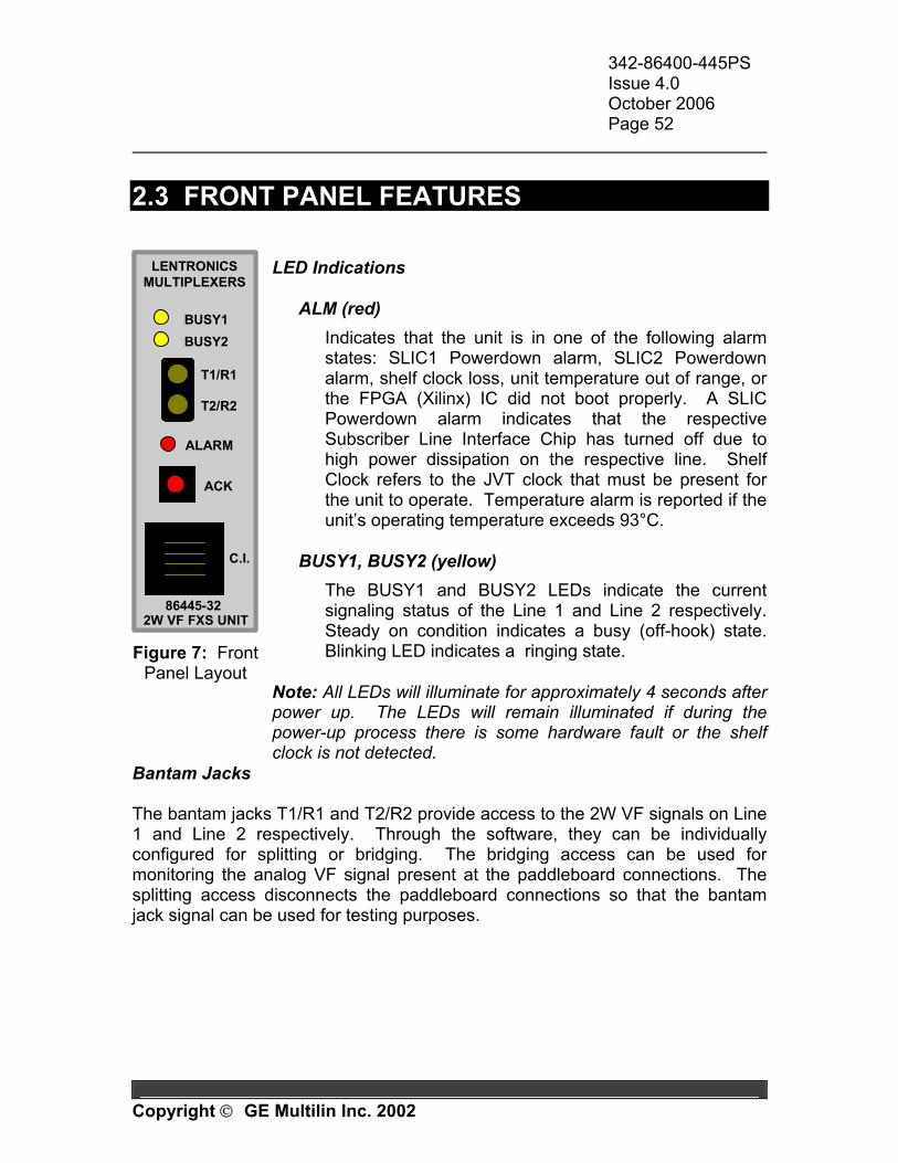
LED Indications
ALM (red)
Indicates that the unit is in one of the following alarm states: SLIC1 Powerdown alarm, SLIC2 Powerdown alarm, shelf clock loss, unit temperature out of range, or the FPGA (Xilinx) IC did not boot properly. A SLIC Powerdown alarm indicates that the respective Subscriber Line Interface Chip has turned off due to high power dissipation on the respective line. Shelf Clock refers to the JVT clock that must be present for the unit to operate. Temperature alarm is reported if the unit’s operating temperature exceeds 93°C.
BUSY1, BUSY2 (yellow)
The BUSY1 and BUSY2 LEDs indicate the current signaling status of the Line 1 and Line 2 respectively. Steady on condition indicates a busy (off-hook) state. Blinking LED indicates a ringing state.
Note: All LEDs will illuminate for approximately 4 seconds after power up. The LEDs will remain illuminated if during the power-up process there is some hardware fault or the shelf clock is not detected.
Bantam Jacks The bantam jacks T1/R1 and T2/R2 provide access to the 2W VF signals on Line 1 and Line 2 respectively. Through the software, they can be individually configured for splitting or bridging. The bridging access can be used for monitoring the analog VF signal present at the paddleboard connections. The splitting access disconnects the paddleboard connections so that the bantam jack signal can be used for testing purposes.
2W VF FXS UNIT
C.I.
86445-32
ACK
ALARM
BUSY1
LENTRONICSMULTIPLEXERS
T1/R1
T2/R2
BUSY2
2W VF FXS UNIT
C.I.
86445-32
ACK
ALARM
BUSY1
LENTRONICSMULTIPLEXERS
T1/R1
T2/R2
BUSY2
Figure 7: Front
Panel Layout
342-86400-445PS Issue 4.0 October 2006 Page 53
Copyright GE Multilin Inc. 2002
Push-button (ACK) The first use of the push-button is a LED and microprocessor test. If the 2W FXS unit is operating normally, holding the front panel pushbutton down causes all the LEDs to light. The main use for this test is to determine that the front panel LEDs are functional and that the microprocessor firmware code is running normally (microprocessor is not locked up). Note: The microprocessor test does not cause any disruption in traffic. The second use of the push-button is to put the unit into a "sleep state". This state is enabled when the 2W FXS unit is inserted in the shelf with the ACK button pressed. In this condition, the micro ignores all settings until a local VistaNET connection is established to the unit’s CI port. On establishing this connection, the software will automatically clear the unit’s Channel settings (will set them to “–“) and restart the unit at which point the user can configure the unit to the desired settings. If the unit is inserted with the ACK button pressed and then removed and inserted normally (no local VistaNET connected), all previous settings will remain. Note: Inserting the unit into the equipment shelf without the ACK button pressed may cause a traffic disruption in an in-service system. Craft Interface (C.I.) Jack The Craft Interface allows a user to connect a PC computer serial (COM) port to the unit. The CI is an RJ-11 connector, which transmits and receives a 9600 b/s RS-232 signal. A Microsoft-Windows-based VistaNET software allows the user to configure the unit and monitor its status through the CI port.

342-86400-445PS Issue 4.0 October 2006 Page 54
Copyright GE Multilin Inc. 2002
2.4 UNIT DESCRIPTION The 86445-32 2W FXS/PLAR unit supports two independent analog telephone lines. For each provisioned line, it uses one DS0 channel on a JVT bus. The unit occupies one shelf slot in a JungleMUX equipment shelf and comprises 087-86445-32 circuit assembly board. The board comprises two line interface circuits, 68CK16Z1 microcontroller, Xilinx Spartan XCS30/XL FPGA, 128Kbyte RAM (U6), 256Kbyte flash EEPROM (U7), clock synchronizer and multiplier circuit (U11), temperature monitor (U5), 5 V to 3.3V voltage converter (U19), front-panel components and system interface components. Each line interface circuit is comprised of Si3210M ProSLIC device (U13 and U18), Si3201 linefeed interface ICs (U12 and U17) and DC-DC converter circuit. The ProSLIC device integrates SLIC (subscriber line integrated circuit), PCM Coder/Decoder and DC-DC converter control functions. Two DC-DC converter circuits generate talk battery and ringing voltages from +5 Vdc shelf power supply. The 86445-32 2W FXS unit is capable of a local loopback that ignores the incoming signal from the far end and loops back the incoming local signal to the local end. The unit is also capable of a line loopback that ignores the local incoming signal and loops back the far-end receive digitized VF signal to the remote end. All user connections (Tip and Ring for each of the two lines) are made on the 4-pin terminal block available on the 86445-92 paddleboard. The pinout arrangements are provided in the Installation portion of the manual. In addition to the terminal block, the paddleboard comprises protection devices for each line – TeleLink fuses (F1, F2, F3 and F4) and Dual SLIC Protectors (U1 and U2). A simplified Block Diagram has been included at the end of this section and can be used as a reference for the following signal paths analysis; however, the user should refer to schematics EAS-86445-32 for complete circuit descriptions.
342-86400-445PS Issue 4.0 October 2006 Page 55
Copyright GE Multilin Inc. 2002
Transmit Voice Path The Line 1 analog voice signal is sent from the T1,R1 balanced input at the Paddleboard TB1(1,2) to the back connector J1(A6,A5). The signal is sent via bantam jack J2, through Si3201 line interface circuit U12(1,3) to the ProSLIC device U13 that performs 2W to 4W hybrid function, signal attenuation/ amplification, signal filtering and A-D conversion with µ-law compression. The resulting 64 kb/s PCM data stream (DTX1) is passed to the FPGA U10(24). Line 2 transmit signal is processed identically on its own path. The resulting 64kb/s PCM data stream (DTX2) is passed to the FPGA U10(46). The FPGA maps DTX1 and DTX2 data streams into the corresponding DS0 channels set by the user. The FPGA outputs the data on its pin 5 to the JVT shelf driver U15. The JVT bus transmit interface at J1(C14,A14) consists of a balanced RS-485 signal pair. The FPGA receives its clock source from the JVT Clock through the JVT bus receiver U16. The JVT serial bus operates at 2.592 MHz. The microprocessor provides the information to the FPGA, which conditions the solid-state relay U8 across the bantam jack for bridging or splitting configuration. Receive Voice Path The DS0 channel data is received from the JVT bus at J1(A16,C16) by the bus receiver U14 and after level conversion sent to the FPGA pin 12. The FPGA converts the received DS0 channel data into respective 64kb/s PCM data streams DRX1 and DRX2 and passes them to the respective ProSLIC device. Each ProSLIC device converts its received data stream back to analog voice signal and sends it through Si3201 line interface circuit and via bantam jack J2 to the back connector J1(A6,A5) for Line 1 (T1,R1) and J1(A8,A9) for Line 2 (T2,R2) respectively. From the back connector J1, the signals are forwarded to the paddleboard and are available for customer connections on TB1(1,2) and TB1 (3,4) for Line 1 (T1,R1) and Line 2 (T2, R2) respectively.
342-86400-445PS Issue 4.0 October 2006 Page 56
Copyright GE Multilin Inc. 2002
Transmit Signaling Each ProSLIC device continuously monitors its respective line and detects on-hook, off-hook, or ring-ground (for GS application) states. The microcontroller reads ProSLIC registers and encodes the line states into A and B signaling bits to be passed to the FPGA. The FPGA maps the signaling bits into the VT overhead bytes in the position determined by the DS0 channel numbers set. The Transmit Signaling condition can be monitored through the VistaNET software. Receive Signaling The receive signaling bits are extracted from the received JVT bus stream by the FPGA and then passed to the microcontroller. The microcontroller interprets the received signaling bits in conjunction with the transmit signaling bits (line on-hook or off-hook) and issues the command to the respective ProSLIC device to output or not to output ringing voltage to its line. In GS application, the ProSLIC device also sets Tip to ground when instructed. The Receive Signaling condition can be monitored through the VistaNET software. Microprocessor Operation U4, a 68HC16Z1 microprocessor, is the CPU for the 86445-32 2W FXS unit. For memory the micro uses a 128 kbytes RAM (U6), a 128 kbytes Flash EEROM (U7) and a 1-kbyte internal high speed RAM. The CPU provides the following:
• Communication with the user through the Craft Interface port
• Control of all front panel LEDs and monitoring of the ACK push-button
• Monitoring of the unit temperature sensor (U5) and reporting unit temperature
• Unit initialization and configuration of the FPGA (U10)
342-86400-445PS Issue 4.0 October 2006 Page 57
Copyright GE Multilin Inc. 2002
• Initialization and calibration of ProSLIC devices (U13 and U18)
• Monitoring and control of ProSLIC and FPGA registers • Communication of the unit status and alarm information to the JIF-Share
unit for the Network Management System (NMS) • Processing the configuration requests from CI and/or NMS.
The 32.768 kHz crystal Y1 forms an oscillator with the micro, which multiplies it for an internal 16.78 MHz CPU clock. The Flash memory (U7) contains the operating code for the micro, configuration code for the FPGA, and user settings for the unit.
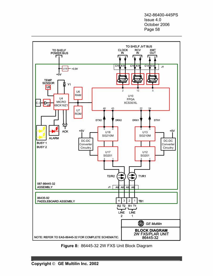
342-86400-445PS Issue 4.0 October 2006 Page 58
Copyright GE Multilin Inc. 2002
J1
BLOCK DIAGRAM2W FXS/PLAR UNIT
86445-32
U10FPGA
XCS30/XL
ACK
BUSY 1
ALARM
U5
TEMP SENSOR
+5V
TO SHELF POWER BUS
TO SHELF JVT BUS
U3C.I.
Y1
J1
CLOCK IN
RCV IN
XMT OUT
U16 U14 U15
U6RAM
U7ROM
U4MICRO
68CK16Z1
GE Multilin
087-86445-32ASSEMBLY
NOTE: REFER TO EAS-86445-32 FOR COMPLETE SCHEMATIC.
LINE2
R2 T2 R1 T1
TB186435-92PADDLEBOARD ASSEMBLY 1234
LINE1
T1/R1T2/R2
22 24
U12SI3201
U13SI3210M
DTX1DRX1
2 12 5
C15 A15 C16 A16 C14 A14
4346
DTX2 DRX2
U17SI3201
U18SI3210M
4 545
1313
U19 +3.3V
A9 A8 A5 A6
DC-DCConverterCircuitry
+5V
DC-DCConverterCircuitry
+5V
BUSY 2
J1
BLOCK DIAGRAM2W FXS/PLAR UNIT
86445-32
U10FPGA
XCS30/XL
ACK
BUSY 1
ALARM
U5
TEMP SENSOR
+5V
TO SHELF POWER BUS
TO SHELF JVT BUS
U3C.I.
Y1
J1
CLOCK IN
RCV IN
XMT OUT
U16 U14 U15
U6RAM
U7ROM
U4MICRO
68CK16Z1
GE Multilin
087-86445-32ASSEMBLY
NOTE: REFER TO EAS-86445-32 FOR COMPLETE SCHEMATIC.
LINE2
R2 T2 R1 T1
TB186435-92PADDLEBOARD ASSEMBLY 1234
LINE1
T1/R1T2/R2
22 24
U12SI3201
U13SI3210M
DTX1DRX1
2 12 5
C15 A15 C16 A16 C14 A14
4346
DTX2 DRX2
U17SI3201
U18SI3210M
4 545
1313
U19 +3.3V
A9 A8 A5 A6
DC-DCConverterCircuitry
+5V
DC-DCConverterCircuitry
+5V
BUSY 2
Figure 8: 86445-32 2W FXS Unit Block Diagram
342-86400-445PS Issue 4.0 October 2006 Page 59
Copyright GE Multilin Inc. 2002
2.5 INSTALLATION The following section provides information for installing an 86445-32 FXS unit. The unit is shipped from the factory configured as per the Node Assignment Drawing for the purchased system. All spare units or loose units are shipped with factory default settings in memory.
CAUTION The 86445-32 2W FXS unit has ESDS components and therefore standard static protection precautions should be observed when handling, packing
or shipping the unit. Pre-installation Visually check the unit for damage. Ensure that screws are firmly tightened and in place. Keep the shipping containers and packing materials for future use. If a unit is damaged, file a claim with the shipping agent or the local GE Multilin representative. Shelf Position The 86445-32 2W FXS unit and associated Paddleboard can be inserted in slots 2 to 14 of an 86430-02 Expansion Shelf or in slots 2 to 11 of an 86430-01 Common Equipment Shelf. Figure 9 shows a typical rack layout for a ring configured system as it appears on a NAD. Furthermore, ensure the selected shelf slot is traceable to the proper JVT port. The user may refer to the 86485 JIF-Share Unit TPIM and 86430 Equipment Shelf TPIM for more information.
CAUTION To facilitate the unit's heat dissipation, one of the two adjacent shelf slots shall be unequipped if: - both lines are provisioned and longer than 1500 ft, and - it is expected to have both lines simultaneously off-hook over an
extended period of time, and - the ambient temperature around the JungleMUX shelf is higher than
40°C.
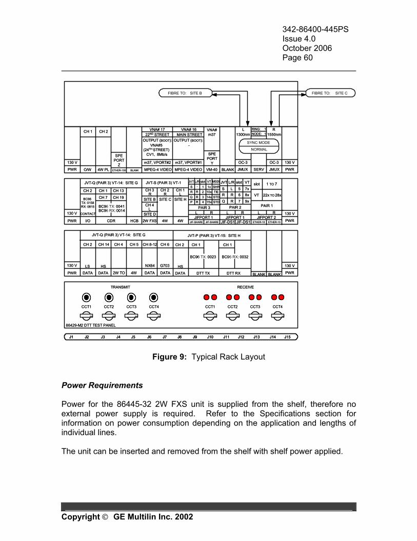
342-86400-445PS Issue 4.0 October 2006 Page 60
Copyright GE Multilin Inc. 2002
J1 J15J2 J3 J4 J5 J6 J7 J8 J9 J10 J11 J12 J13 J14
CCT1 CCT2 CCT3 CCT4
TRANSMIT RECEIVE
86429-M2 DTT TEST PANEL
CCT1 CCT2 CCT3 CCT4
PWR
130 V
4W2W FXS 4W PWR
130 V
HCBCDR
CONTACT
I/O
S 1x SHR
JIFPORT 1 JIF-SHARE
L R
CH 1
CH 7
CH 13
CH 19
CH 2
JVT-S (PAIR 3) VT-1JVT-Q (PAIR 3) VT-14: SITE G
CH 3 R
CH 1 L
CH 2 R
PAIR 2
JIF-DS1 JIF-DS1
-
JIFPORT 1
Q 7R 9x
R 6R 8xS 5L 7x
JVT L/R VTJVT VT
1
MODEL/R
L R
SITE B SITE C SITE H
BC96 TX: 0041
R 2R 10x TIEQ 3R 14x STDP 4R 15x STD
PAIR 3
JIF-SHARE
PWR
130 V
PWR
130 V
2W TO 4W DATA DATA
JVT-Q (PAIR 3) VT-14: SITE G
BC96 RX: 0014
CH 4
BLANK
BC96 TX: 0158RX: 0815
CH 5
NX64
CH 8-12
slotslot
CH 6
G703
PWR
130 V
PWR
130 V
JMUX SERV JMUX
OC-3 OC-3
L R
SITE BFIBRE TO: SITE CFIBRE TO:
O/W VM-40
SPEPORT
Y
1300nmRING: 1 NODE: 1 1550nm
4W PL BLANK
VNA#m37
SYNC MODE
NORMAL
CH 1 CH 2
CH 2 CH 14
LS
DATA
HS
DATA
JVT-P (PAIR 3) VT-15: SITE H
DTT RXDTT TX
CH 1 CH 1
BC96 TX: 0023
CH 2
HS
DATA
BC96 RX: 0032
VT 22x TO 28x
PAIR 1
1 TO 7
JIFPORT 2L R
ETHER-10
slot
BLANK
ETHER-10
BLANK
SPEPORT
ZETHER-100
CH 4 L
SITE D
MPEG-4 VIDEO
VNA# 17
MPEG-4 VIDEO
m37, VPORT#2
OUTPUT (BOOT):VNA#5
(24TH STREET) CV1, 8Mb/s
m37, VPORT#1
22ND STREETVNA# 16
MAIN STREET
-OUTPUT (BOOT):
J1 J15J2 J3 J4 J5 J6 J7 J8 J9 J10 J11 J12 J13 J14J1 J15J2 J3 J4 J5 J6 J7 J8 J9 J10 J11 J12 J13 J14
CCT1 CCT2 CCT3 CCT4
TRANSMIT RECEIVE
86429-M2 DTT TEST PANEL
CCT1 CCT2 CCT3 CCT4
PWR
130 V
4W2W FXS 4W PWR
130 V
HCBCDR
CONTACT
I/O
S 1x SHR
JIFPORT 1 JIF-SHARE
L R
CH 1
CH 7
CH 13
CH 19
CH 2
JVT-S (PAIR 3) VT-1JVT-Q (PAIR 3) VT-14: SITE G
CH 3 R
CH 1 L
CH 2 R
PAIR 2
JIF-DS1 JIF-DS1
-
JIFPORT 1
Q 7R 9x
R 6R 8xS 5L 7x
JVT L/R VTJVT VT
1
MODEL/R
L R
SITE B SITE C SITE H
BC96 TX: 0041
R 2R 10x TIEQ 3R 14x STDP 4R 15x STD
PAIR 3
JIF-SHARE
PWR
130 V
PWR
130 V
2W TO 4W DATA DATA
JVT-Q (PAIR 3) VT-14: SITE G
BC96 RX: 0014
CH 4
BLANK
BC96 TX: 0158RX: 0815
CH 5
NX64
CH 8-12
slotslot
CH 6
G703
PWR
130 V
PWR
130 V
JMUX SERV JMUX
OC-3 OC-3
L R
SITE BFIBRE TO: SITE CFIBRE TO:
O/W VM-40
SPEPORT
Y
1300nmRING: 1 NODE: 1 1550nm
4W PL BLANK
VNA#m37
SYNC MODE
NORMAL
CH 1 CH 2
CH 2 CH 14
LS
DATA
HS
DATA
JVT-P (PAIR 3) VT-15: SITE H
DTT RXDTT TX
CH 1 CH 1
BC96 TX: 0023
CH 2
HS
DATA
BC96 RX: 0032
VT 22x TO 28x
PAIR 1
1 TO 7
JIFPORT 2L R
ETHER-10
slot
BLANK
ETHER-10
BLANK
SPEPORT
ZETHER-100
CH 4 L
SITE D
MPEG-4 VIDEO
VNA# 17
MPEG-4 VIDEO
m37, VPORT#2
OUTPUT (BOOT):VNA#5
(24TH STREET) CV1, 8Mb/s
m37, VPORT#1
22ND STREETVNA# 16
MAIN STREET
-OUTPUT (BOOT):
Figure 9: Typical Rack Layout Power Requirements Power for the 86445-32 2W FXS unit is supplied from the shelf, therefore no external power supply is required. Refer to the Specifications section for information on power consumption depending on the application and lengths of individual lines. The unit can be inserted and removed from the shelf with shelf power applied.
342-86400-445PS Issue 4.0 October 2006 Page 61
Copyright GE Multilin Inc. 2002
Inserting the Unit in the Shelf
WARNING For systems already in service, inserting a 2W FXS unit without the ACK
button pressed may cause traffic disruption in a DS0 channel on the same JVT.
WARNING
Do not use the red tab to force the unit into the shelf as this could result in damage to the red tab.
1. Insert the unit to the point of resistance. 2. With the “ACK” button pressed, gently seat the unit into the shelf by pressing
the front panel. (Ensure the red tab is not preventing the unit from insertion.)
Note: The 2W FXS unit inserted with ACK button pressed is in the “Sleep mode” and the DS0 channel assignment on the unit is disabled at that point.
3. Use VistaNET (local connection) to program the unit in accordance to the NAD for the given node. Refer to the Configuration Section of this manual.
Removing the Unit from the Shelf 1. Use the red tab to remove the unit from the shelf. Note: The Copy-and-Paste available in VistaNET (local connection only) can be used to copy the configuration from the unit to be removed to the replacement unit. For more information refer to the Configuration section.
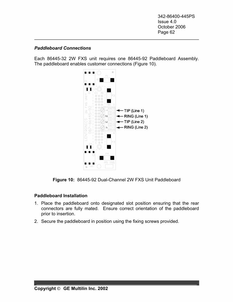
342-86400-445PS Issue 4.0 October 2006 Page 62
Copyright GE Multilin Inc. 2002
Paddleboard Connections Each 86445-32 2W FXS unit requires one 86445-92 Paddleboard Assembly. The paddleboard enables customer connections (Figure 10).
TIP (Line 1)RING (Line 1)TIP (Line 2)RING (Line 2)
TIP (Line 1)RING (Line 1)TIP (Line 2)RING (Line 2)
Figure 10: 86445-92 Dual-Channel 2W FXS Unit Paddleboard Paddleboard Installation 1. Place the paddleboard onto designated slot position ensuring that the rear
connectors are fully mated. Ensure correct orientation of the paddleboard prior to insertion.
2. Secure the paddleboard in position using the fixing screws provided.
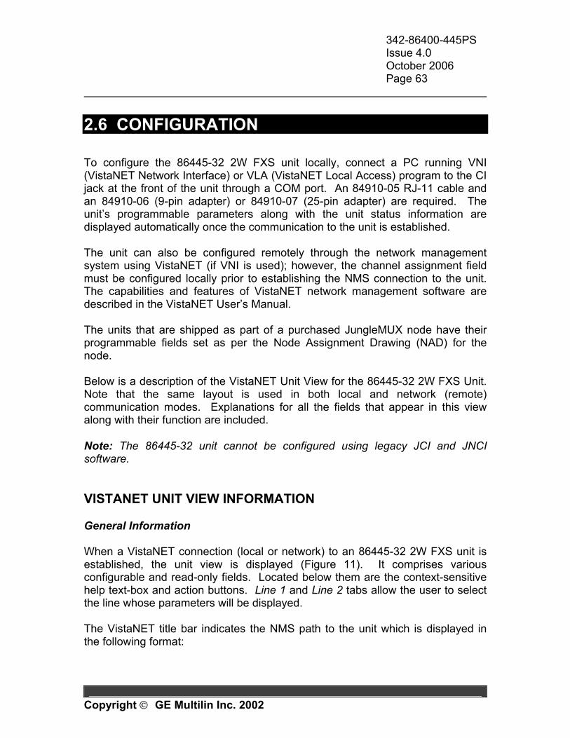
342-86400-445PS Issue 4.0 October 2006 Page 63
Copyright GE Multilin Inc. 2002
2.6 CONFIGURATION To configure the 86445-32 2W FXS unit locally, connect a PC running VNI (VistaNET Network Interface) or VLA (VistaNET Local Access) program to the CI jack at the front of the unit through a COM port. An 84910-05 RJ-11 cable and an 84910-06 (9-pin adapter) or 84910-07 (25-pin adapter) are required. The unit’s programmable parameters along with the unit status information are displayed automatically once the communication to the unit is established. The unit can also be configured remotely through the network management system using VistaNET (if VNI is used); however, the channel assignment field must be configured locally prior to establishing the NMS connection to the unit. The capabilities and features of VistaNET network management software are described in the VistaNET User’s Manual. The units that are shipped as part of a purchased JungleMUX node have their programmable fields set as per the Node Assignment Drawing (NAD) for the node. Below is a description of the VistaNET Unit View for the 86445-32 2W FXS Unit. Note that the same layout is used in both local and network (remote) communication modes. Explanations for all the fields that appear in this view along with their function are included. Note: The 86445-32 unit cannot be configured using legacy JCI and JNCI software. VISTANET UNIT VIEW INFORMATION General Information When a VistaNET connection (local or network) to an 86445-32 2W FXS unit is established, the unit view is displayed (Figure 11). It comprises various configurable and read-only fields. Located below them are the context-sensitive help text-box and action buttons. Line 1 and Line 2 tabs allow the user to select the line whose parameters will be displayed. The VistaNET title bar indicates the NMS path to the unit which is displayed in the following format:
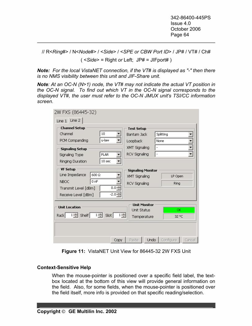
342-86400-445PS Issue 4.0 October 2006 Page 64
Copyright GE Multilin Inc. 2002
// R<Ring#> / N<Node#> / <Side> / <SPE or CBW Port ID> / JP# / VT# / Ch#
( <Side> = Right or Left; JP# = JIFport# ) Note: For the local VistaNET connection, if the VT# is displayed as "-" then there is no NMS visibility between this unit and JIF-Share unit. Note: At an OC-N (N>1) node, the VT# may not indicate the actual VT position in the OC-N signal. To find out which VT in the OC-N signal corresponds to the displayed VT#, the user must refer to the OC-N JMUX unit's TSI/CC information screen.
Figure 11: VistaNET Unit View for 86445-32 2W FXS Unit Context-Sensitive Help
When the mouse-pointer is positioned over a specific field label, the text-box located at the bottom of this view will provide general information on the field. Also, for some fields, when the mouse-pointer is positioned over the field itself, more info is provided on that specific reading/selection.
342-86400-445PS Issue 4.0 October 2006 Page 65
Copyright GE Multilin Inc. 2002
Configure button
Writes the changes made in configurable fields to the unit.
Note: Any changes made in the configurable fields will not take effect until after the Configure button is pressed. Multiple fields may be configured simultaneously.
Undo button Undoes the configuration changes written to the unit when the Configure button was pressed last time. It is possible to keep undoing previously performed configuration changes until the Undo button becomes disabled.
Note: Upon moving to a different unit, the VistaNET will forget the information on the last applied configuration changes. Therefore, the Undo action is possible only for the same unit to which the Configuration changes have been applied.
Cancel button Cancels the changes made in configurable fields and refreshes them with the previously displayed values.
Note: Only the changes made after the last Configure (or Undo) action can be cancelled.
Copy and Paste buttons These fields allow the user to copy the unit configuration settings to another unit of the same type. Click on Copy at the source unit, move the cable to the destination unit, and click on Paste. All the fields whose configurations are about to be changed are highlighted. Click on the Configure button to write the changes to the destination unit.
Note: The source unit configuration settings are stored in the “clipboard” and may be applied to unlimited number of destination units of the same type. Note: The user is allowed to modify the selections prior to pressing the Configure button. Note: The user may opt not to apply the changes to the destination unit in which case the Cancel button shall be selected after the Paste action.
342-86400-445PS Issue 4.0 October 2006 Page 66
Copyright GE Multilin Inc. 2002
Field Descriptions All fields (programmable and read-only) are grouped in frames based on their function. Channel Setup Channel
Allows DS0 channel assignment to the selected VF line. Channel number is selectable from 1 to 24. A ‘-‘ (default selection) indicates that a channel has not been assigned. Each channel occupies its own DS0 (64 kb/s) time slot on the JVT. Ensure that the channel(s) assigned on this unit are not assigned on any other DS0 level unit on the same JVT. The corresponding far-end unit interface must be given the same channel assignment.
Note: The channels assigned to the two VF lines do not have to be consecutive.
PCM Companding
Sets the companding law applied in the A/D converter. The µ-law is used in North America and Japan. A-law is used in Europe and the rest of the world.
Signalling Setup Signalling Type
May be set to Loop Start (LS), Ground Start (GS) or Private Line Automatic Ringdown (PLAR). The far-end unit interface must be set for the same signaling type.
Note: Although the 86445-32 2W FXS unit is normally used with either 86445-41 2W FXO unit (for LS and GS applications) or 86445-3X 2W FXS unit (for PLAR application) at the far end, it can also be used with an 86444 4W VF unit when no signaling is required. This may be utilized for VF channel testing.
Ringing Duration
Sets the ringing duration when in PLAR mode. May be set to 10 sec, 20 sec, 60 sec and Indefinite.
Note: This field is active only if PLAR is selected in the Signalling Type field. Note: In the Loop Start (LS) and Ground Start (GS) signaling modes the ringing duration is not limited.
342-86400-445PS Issue 4.0 October 2006 Page 67
Copyright GE Multilin Inc. 2002
VF Setup Line Impedance
May be set to either 600 Ω or 900 Ω in series with or without 2.16 µF of line capacitance.
Note: It is important to match the actual line impedance with the 2W FXS unit's input impedance to maximize the amount of power to be transferred from the telephone to the line. Impedance mismatches create side tones which in the worst case are perceived as echoes. The addition of 2.16 µF adds capacitive reactance to the line that may reduce noise and distortion.
NBOC
May be set to 0 nF, 4.7 nF or 10 nF. This may be used for additional line capacitance compensation.
Note: Network build-out capacitance is added to provide additional line balancing. Generally, no additional NBOC is required for lines shorter than 2000 ft (600 m).
Transmit Level [dBm]
Software selectable from -9.5 to +5.0 dBm in 0.1 dB increments. Default is 0 dBm.
Note: The Line Impedance parameter shall be set before Transmit Level because any subsequent changes to the Line Impedance setting may also alter the Transmit Level setting.
Receive Level [dBm]
Software selectable from -15.0 to +5.0 dBm in 0.1 dB increments. Default is -2 dBm.
Note: The Line Impedance parameter shall be set before Receive Level because any subsequent changes to the Line Impedance setting may also alter the Receive Level setting.
Test Setup Bantam Jack
May be set for Bridging or Splitting (default). Bridging mode allows for monitoring of the circuit via bantam jacks on the unit face plate.
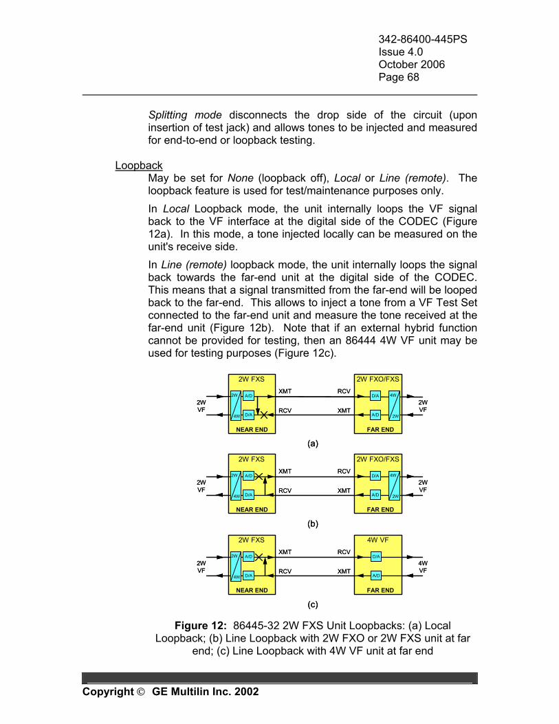
342-86400-445PS Issue 4.0 October 2006 Page 68
Copyright GE Multilin Inc. 2002
Splitting mode disconnects the drop side of the circuit (upon insertion of test jack) and allows tones to be injected and measured for end-to-end or loopback testing.
Loopback
May be set for None (loopback off), Local or Line (remote). The loopback feature is used for test/maintenance purposes only. In Local Loopback mode, the unit internally loops the VF signal back to the VF interface at the digital side of the CODEC (Figure 12a). In this mode, a tone injected locally can be measured on the unit's receive side. In Line (remote) loopback mode, the unit internally loops the signal back towards the far-end unit at the digital side of the CODEC. This means that a signal transmitted from the far-end will be looped back to the far-end. This allows to inject a tone from a VF Test Set connected to the far-end unit and measure the tone received at the far-end unit (Figure 12b). Note that if an external hybrid function cannot be provided for testing, then an 86444 4W VF unit may be used for testing purposes (Figure 12c).
RCV
XMT
2W FXS 4W VF
2W
4W
XMT
RCV2WVF
4WVF
NEAR END FAR END
A/D
D/A
D/A
A/D
(c)
RCV
XMT
2W FXS 2W FXO/FXS
2W
4W
XMT
RCV
4W
2W
2WVF
2WVF
NEAR END FAR END
A/D
D/A
D/A
A/D
RCV
XMT
2W FXS 2W FXO/FXS
2W
4W
XMT
RCV
4W
2W
2WVF
2WVF
(a)
NEAR END FAR END
(b)
D/A
A/D
A/D
D/A
RCV
XMT
2W FXS 4W VF
2W
4W
2W
4W
XMT
RCV2WVF
4WVF
NEAR END FAR END
A/D
D/A
D/A
A/D
(c)
RCV
XMT
2W FXS 2W FXO/FXS
2W
4W
2W
4W
XMT
RCV
4W
2W
4W
2W
2WVF
2WVF
NEAR END FAR END
A/D
D/A
D/A
A/D
RCV
XMT
2W FXS 2W FXO/FXS
2W
4W
2W
4W
XMT
RCV
4W
2W
4W
2W
2WVF
2WVF
(a)
NEAR END FAR END
(b)
D/A
A/D
A/D
D/A
Figure 12: 86445-32 2W FXS Unit Loopbacks: (a) Local
Loopback; (b) Line Loopback with 2W FXO or 2W FXS unit at far end; (c) Line Loopback with 4W VF unit at far end
342-86400-445PS Issue 4.0 October 2006 Page 69
Copyright GE Multilin Inc. 2002
Note: When in Line Loopback test mode, the unit's Transmit and Receive Levels (VF Setup window) should be set to 0 dBm. Note: This field must be set to 'None' when not being used for test or maintenance purposes.
XMT Signalling
Allows the user to set a specific signaling condition that will be sent to the far-end unit and is used for test/maintenance purposes only. The signaling options available depend on the Signalling Type selected (see Signalling Setup window).
Note: This field must be set to ‘-‘ when not being used for test or maintenance purposes. Note: When testing from near end to far end, the far-end unit Receive Signalling should be configured to '-'. Note: The unit's yellow (BUSY) LED illuminates only if an OFF-HOOK condition is initiated from an external source (i.e. signaling test set or telephone).
RCV Signalling Allows the user to set a specific signaling condition that will be sent to the local drop equipment and is used for test/maintenance purposes only. The options available depend on the Signalling Type selected (see Signalling Setup window).
Note: This field must be set to ‘-‘ when not being used for test or maintenance purposes.
Signalling Monitor XMT Signalling
Shows current signaling status sent towards the far-end unit. Receive Signalling
Shows current signaling status received from the far-end unit (unless overridden by the locally forced RCV Signalling test condition in which case the forced condition is displayed).
342-86400-445PS Issue 4.0 October 2006 Page 70
Copyright GE Multilin Inc. 2002
Unit Location Rack Number (use is optional)
Identifies the rack or cabinet (1 to 64) in which the unit is located. This information may be utilized on the NMS (Network Management System).
Shelf Number (use is optional)
Identifies the shelf (1 to 64) in which the unit is located. This information may be utilized on the NMS.
Slot Number (use is optional)
Identifies the slot position within the shelf (1 to 15) in which the unit is located. This information may be utilized on the NMS.
Unit Monitor Unit Status
Displays the current status of the unit. The possible readings are: Xilinx Failed to Load, Shelf Clock Loss, SLIC1 Powerdown, SLIC2 Powerdown, High Temperature, or OK (normal operation).
Temperature Displays the current temperature of the unit in ºC. An alarm is raised in the Unit Status field if this reading exceeds 93ºC.
342-86400-445PS Issue 4.0 October 2006 Page 71
Copyright GE Multilin Inc. 2002
2.7 MAINTENANCE and TROUBLESHOOTING Context-Sensitive Help When the mouse-pointer is positioned over a specific field label in the VistaNET Unit View, the text-box located at the bottom of the view will provide general information on the field. Also, for some fields, when the mouse-pointer is positioned over the field itself, more info is provided on that specific reading/selection. This is a useful tool for explaining the capabilities and options of both programmable fields and read-only fields of the unit. Alignment The 86445-32 2W FXS unit must be correctly configured as per the Node Assignment Drawing. All software adjustable fields are detailed in the Configuration section of this manual. The user must ensure that all external connections to the paddleboard are correct. Bantam Jacks The front-panel bantam jacks T1/R1 and T2/R2 provide access to the 2W VF signals on Line 1 and Line 2 respectively. Through the software, they can be individually configured for splitting or bridging. The bridging access can be used for monitoring the analog VF signal present at the paddleboard connections. The splitting access disconnects the paddleboard connections so that the bantam jack signal can be used for testing purposes. Signaling Tests Unit's built-in signaling test features allow for sending a specific, user-selectable signaling condition to the far-end unit and/or to the local drop equipment. Refer to XMT Signalling and RCV Signalling fields in the Configuration section for more information.
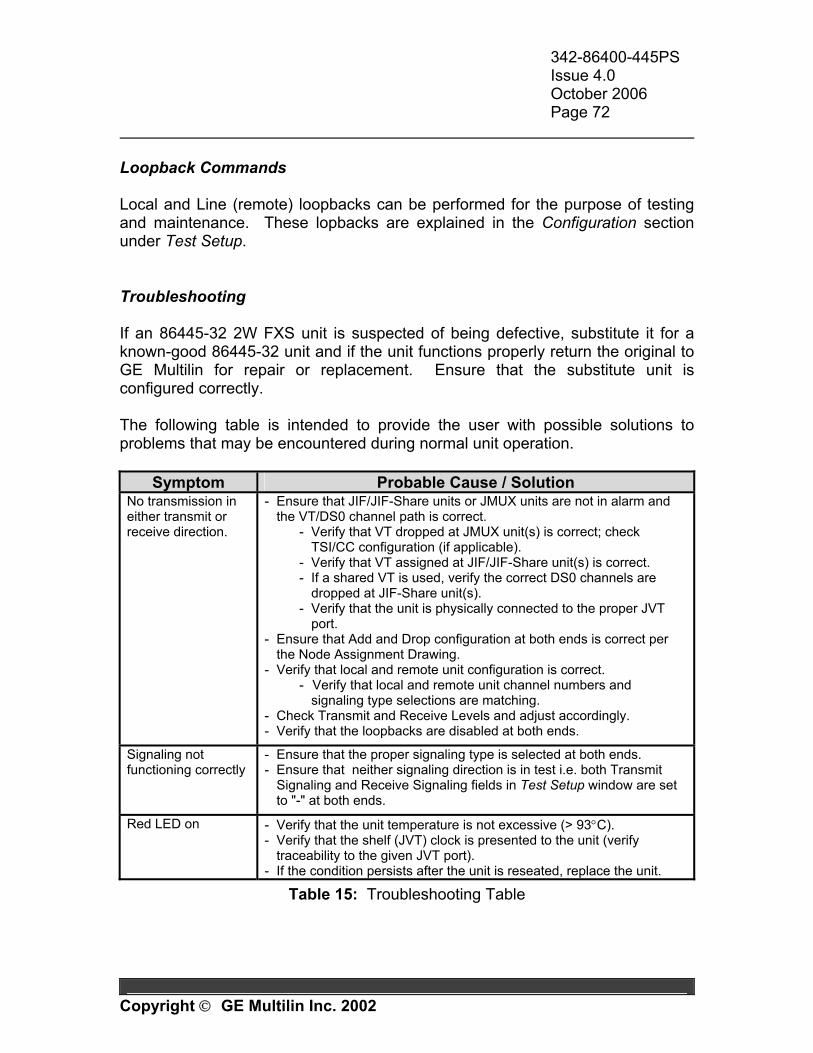
342-86400-445PS Issue 4.0 October 2006 Page 72
Copyright GE Multilin Inc. 2002
Loopback Commands Local and Line (remote) loopbacks can be performed for the purpose of testing and maintenance. These lopbacks are explained in the Configuration section under Test Setup. Troubleshooting If an 86445-32 2W FXS unit is suspected of being defective, substitute it for a known-good 86445-32 unit and if the unit functions properly return the original to GE Multilin for repair or replacement. Ensure that the substitute unit is configured correctly. The following table is intended to provide the user with possible solutions to problems that may be encountered during normal unit operation.
Symptom Probable Cause / Solution No transmission in either transmit or receive direction.
- Ensure that JIF/JIF-Share units or JMUX units are not in alarm and the VT/DS0 channel path is correct.
- Verify that VT dropped at JMUX unit(s) is correct; check TSI/CC configuration (if applicable).
- Verify that VT assigned at JIF/JIF-Share unit(s) is correct. - If a shared VT is used, verify the correct DS0 channels are
dropped at JIF-Share unit(s). - Verify that the unit is physically connected to the proper JVT
port. - Ensure that Add and Drop configuration at both ends is correct per
the Node Assignment Drawing. - Verify that local and remote unit configuration is correct.
- Verify that local and remote unit channel numbers and signaling type selections are matching.
- Check Transmit and Receive Levels and adjust accordingly. - Verify that the loopbacks are disabled at both ends.
Signaling not functioning correctly
- Ensure that the proper signaling type is selected at both ends. - Ensure that neither signaling direction is in test i.e. both Transmit
Signaling and Receive Signaling fields in Test Setup window are set to "-" at both ends.
Red LED on - Verify that the unit temperature is not excessive (> 93°C). - Verify that the shelf (JVT) clock is presented to the unit (verify
traceability to the given JVT port). - If the condition persists after the unit is reseated, replace the unit.
Table 15: Troubleshooting Table
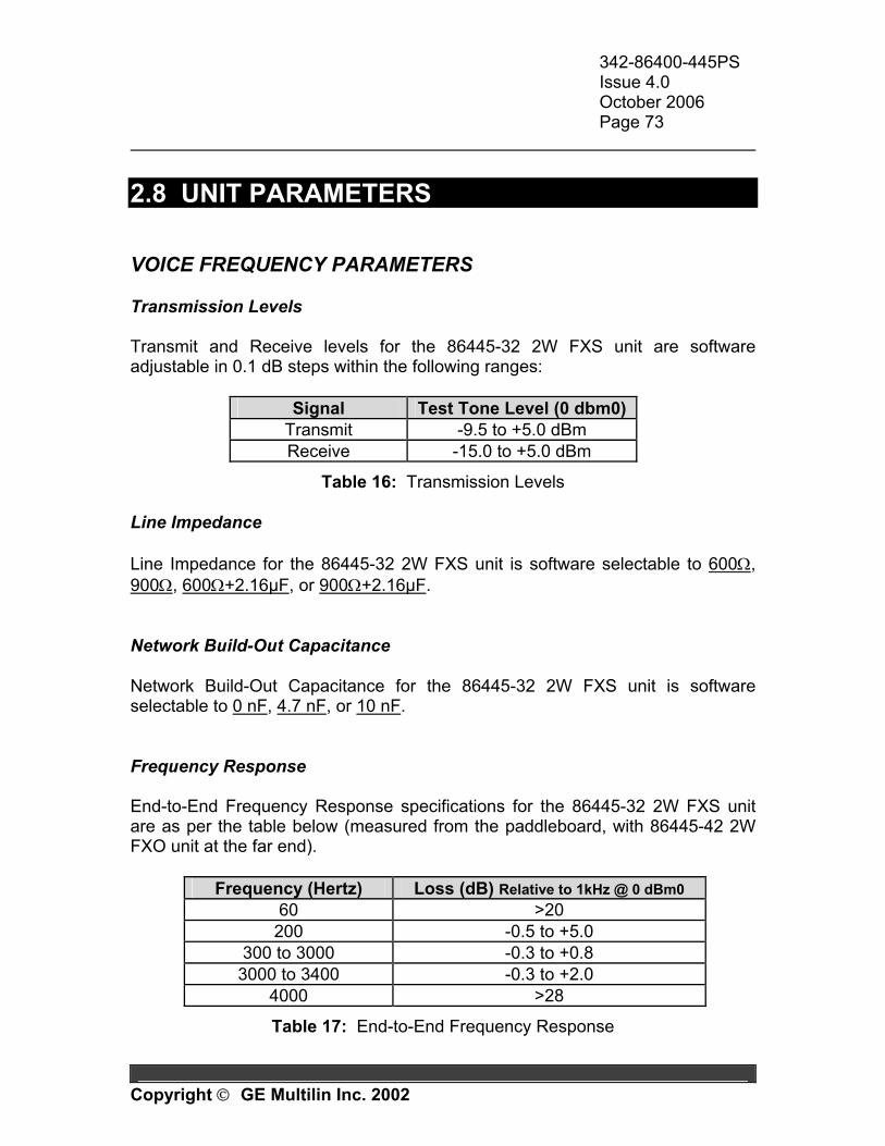
342-86400-445PS Issue 4.0 October 2006 Page 73
Copyright GE Multilin Inc. 2002
2.8 UNIT PARAMETERS VOICE FREQUENCY PARAMETERS Transmission Levels Transmit and Receive levels for the 86445-32 2W FXS unit are software adjustable in 0.1 dB steps within the following ranges:
Signal Test Tone Level (0 dbm0) Transmit -9.5 to +5.0 dBm Receive -15.0 to +5.0 dBm
Table 16: Transmission Levels Line Impedance Line Impedance for the 86445-32 2W FXS unit is software selectable to 600Ω, 900Ω, 600Ω+2.16µF, or 900Ω+2.16µF. Network Build-Out Capacitance Network Build-Out Capacitance for the 86445-32 2W FXS unit is software selectable to 0 nF, 4.7 nF, or 10 nF. Frequency Response End-to-End Frequency Response specifications for the 86445-32 2W FXS unit are as per the table below (measured from the paddleboard, with 86445-42 2W FXO unit at the far end).
Frequency (Hertz) Loss (dB) Relative to 1kHz @ 0 dBm0 60 >20
200 -0.5 to +5.0 300 to 3000 -0.3 to +0.8
3000 to 3400 -0.3 to +2.0 4000 >28
Table 17: End-to-End Frequency Response
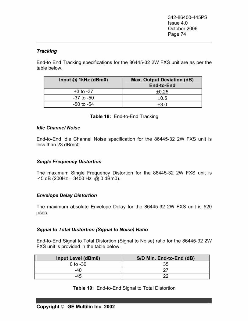
342-86400-445PS Issue 4.0 October 2006 Page 74
Copyright GE Multilin Inc. 2002
Tracking End-to End Tracking specifications for the 86445-32 2W FXS unit are as per the table below.
Input @ 1kHz (dBm0) Max. Output Deviation (dB) End-to-End
+3 to -37 ±0.25 -37 to -50 ±0.5 -50 to -54 ±3.0
Table 18: End-to-End Tracking
Idle Channel Noise End-to-End Idle Channel Noise specification for the 86445-32 2W FXS unit is less than 23 dBrnc0. Single Frequency Distortion The maximum Single Frequency Distortion for the 86445-32 2W FXS unit is -45 dB (200Hz – 3400 Hz @ 0 dBm0). Envelope Delay Distortion The maximum absolute Envelope Delay for the 86445-32 2W FXS unit is 520 µsec. Signal to Total Distortion (Signal to Noise) Ratio End-to-End Signal to Total Distortion (Signal to Noise) ratio for the 86445-32 2W FXS unit is provided in the table below.
Input Level (dBm0) S/D Min. End-to-End (dB) 0 to -30 35
-40 27 -45 22
Table 19: End-to-End Signal to Total Distortion
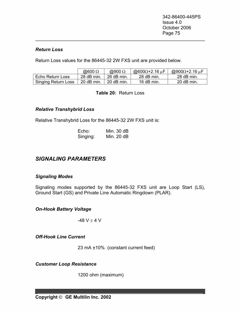
342-86400-445PS Issue 4.0 October 2006 Page 75
Copyright GE Multilin Inc. 2002
Return Loss Return Loss values for the 86445-32 2W FXS unit are provided below. @600 Ω @900 Ω @600Ω+2.16 µF @900Ω+2.16 µF Echo Return Loss 28 dB min. 26 dB min. 28 dB min. 28 dB min. Singing Return Loss 20 dB min. 20 dB min. 16 dB min. 20 dB min.
Table 20: Return Loss
Relative Transhybrid Loss Relative Transhybrid Loss for the 86445-32 2W FXS unit is: Echo: Min. 30 dB Singing: Min. 20 dB SIGNALING PARAMETERS Signaling Modes Signaling modes supported by the 86445-32 FXS unit are Loop Start (LS), Ground Start (GS) and Private Line Automatic Ringdown (PLAR). On-Hook Battery Voltage
-48 V ± 4 V Off-Hook Line Current 23 mA ±10% (constant current feed) Customer Loop Resistance
1200 ohm (maximum)
342-86400-445PS Issue 4.0 October 2006 Page 76
Copyright GE Multilin Inc. 2002
REN connected to line The maximum Ringer Equivalent Number for each line (typically equals to the max number of telephones paralleled) is 2 (two). Ringing Supply The Ringing Supply parameters for the 86445-32 2W FXS unit are:
70 Vac, 20 Hz, sinusoidal balanced ringing Ringing Cadence
PLAR mode: 2 sec ON + 4 sec OFF LS or GS mode: Follows cadence received from far-end
Ringing Duration
In PLAR mode: Configurable to 10 sec, 20 sec, 60 sec or Indefinite. LS or GS mode: Unlimited (driven by the incoming signaling)
Ring Trip
<200 msec Signaling States The Signaling States for FXS mode and PLAR mode are given in the following tables:
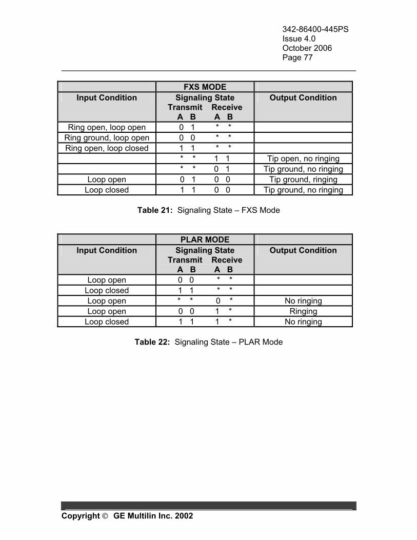
342-86400-445PS Issue 4.0 October 2006 Page 77
Copyright GE Multilin Inc. 2002
FXS MODE
Input Condition Signaling State Transmit Receive
A B A B
Output Condition
Ring open, loop open 0 1 * * Ring ground, loop open 0 0 * * Ring open, loop closed 1 1 * *
* * 1 1 Tip open, no ringing * * 0 1 Tip ground, no ringing
Loop open 0 1 0 0 Tip ground, ringing Loop closed 1 1 0 0 Tip ground, no ringing
Table 21: Signaling State – FXS Mode
PLAR MODE Input Condition Signaling State
Transmit Receive A B A B
Output Condition
Loop open 0 0 * * Loop closed 1 1 * * Loop open * * 0 * No ringing Loop open 0 0 1 * Ringing
Loop closed 1 1 1 * No ringing
Table 22: Signaling State – PLAR Mode
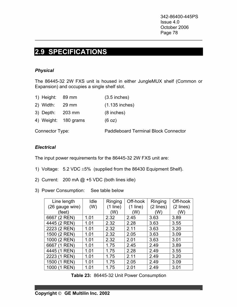
342-86400-445PS Issue 4.0 October 2006 Page 78
Copyright GE Multilin Inc. 2002
2.9 SPECIFICATIONS Physical The 86445-32 2W FXS unit is housed in either JungleMUX shelf (Common or Expansion) and occupies a single shelf slot. 1) Height: 89 mm (3.5 inches) 2) Width: 29 mm (1.135 inches) 3) Depth: 203 mm (8 inches) 4) Weight: 180 grams (6 oz) Connector Type: Paddleboard Terminal Block Connector Electrical The input power requirements for the 86445-32 2W FXS unit are: 1) Voltage: 5.2 VDC ±5% (supplied from the 86430 Equipment Shelf). 2) Current: 200 mA @ +5 VDC (both lines idle) 3) Power Consumption: See table below
Line length (26 gauge wire)
(feet)
Idle (W)
Ringing (1 line)
(W)
Off-hook (1 line)
(W)
Ringing (2 lines)
(W)
Off-hook (2 lines)
(W) 6667 (2 REN) 1.01 2.32 2.45 3.63 3.89 4445 (2 REN) 1.01 2.32 2.28 3.63 3.55 2223 (2 REN) 1.01 2.32 2.11 3.63 3.20 1500 (2 REN) 1.01 2.32 2.05 3.63 3.09 1000 (2 REN) 1.01 2.32 2.01 3.63 3.01 6667 (1 REN) 1.01 1.75 2.45 2.49 3.89 4445 (1 REN) 1.01 1.75 2.28 2.49 3.55 2223 (1 REN) 1.01 1.75 2.11 2.49 3.20 1500 (1 REN) 1.01 1.75 2.05 2.49 3.09 1000 (1 REN) 1.01 1.75 2.01 2.49 3.01
Table 23: 86445-32 Unit Power Consumption

342-86400-445PS Issue 4.0 October 2006 Page 79
Copyright GE Multilin Inc. 2002
The power consumption in ringing state depends on the number of RENs connected to the line. The power consumption in off-hook state depends on the loop resistance of the line. Please take the larger of the two values into account when planning the power budget.
CAUTION To facilitate the unit's heat dissipation, one of the two adjacent shelf slots shall be unequipped if: - both lines are provisioned and longer than 1500 ft, and - it is expected to have both lines simultaneously off-hook over an
extended period of time, and - the ambient temperature around the JungleMUX shelf is higher than
40°C. Environmental 1) Temperature: Guaranteed Performance: -20 to +60°C (-4 to +140°F) Storage: -40 to +70°C (-40 to +158°F) 2) Relative Humidity: 5 to 95% @ 40ºC, non-condensing, 10 days 3) Shipping Altitude: 15,000 meters (50,000 feet) Mechanical 1) Vibration: per MIL-STD 810E 2) Bench Handling: per TS 1-00446.06 EMI/RFI Meets ANSI/IEEE C37.90.2 RFI specification Isolation and Line Protection Meets ANSI/IEEE C37.90.1 for surge withstand and fast transients Meets Bellcore/Telcordia GR 1089-CORE Intra-Building and ITU-T K.20 requirements.
342-86400-445PS Issue 4.0 October 2006 Page 80
Copyright GE Multilin Inc. 2002
Reliability The calculated Mean Time Between Failure (MTBF) as per Bell technical advisory TR-NWT-000332 for the 86445-32 2W FXS unit is: MTBF = 285,000 Hours (32 Years)
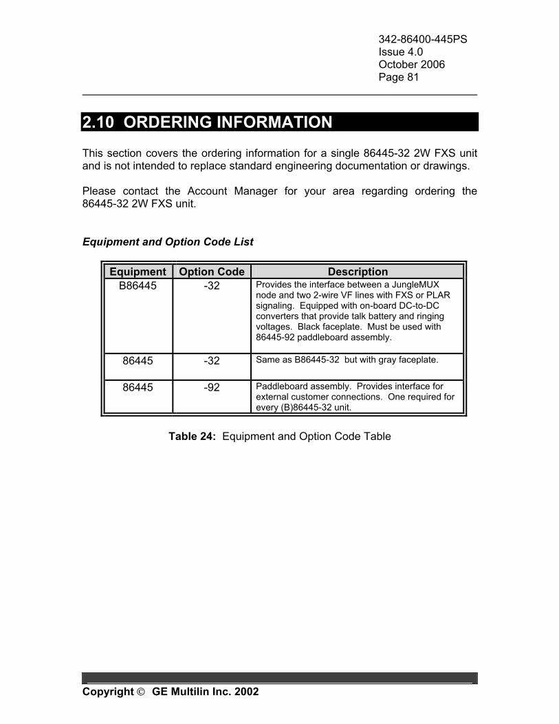
342-86400-445PS Issue 4.0 October 2006 Page 81
Copyright GE Multilin Inc. 2002
2.10 ORDERING INFORMATION This section covers the ordering information for a single 86445-32 2W FXS unit and is not intended to replace standard engineering documentation or drawings. Please contact the Account Manager for your area regarding ordering the 86445-32 2W FXS unit. Equipment and Option Code List
Equipment Option Code Description B86445 -32
Provides the interface between a JungleMUX node and two 2-wire VF lines with FXS or PLAR signaling. Equipped with on-board DC-to-DC converters that provide talk battery and ringing voltages. Black faceplate. Must be used with 86445-92 paddleboard assembly.
86445 -32
Same as B86445-32 but with gray faceplate.
86445 -92 Paddleboard assembly. Provides interface for external customer connections. One required for every (B)86445-32 unit.
Table 24: Equipment and Option Code Table

342-86400-445PS Issue 4.0 October 2006 Page 82
Copyright GE Multilin Inc. 2002
Appendixes
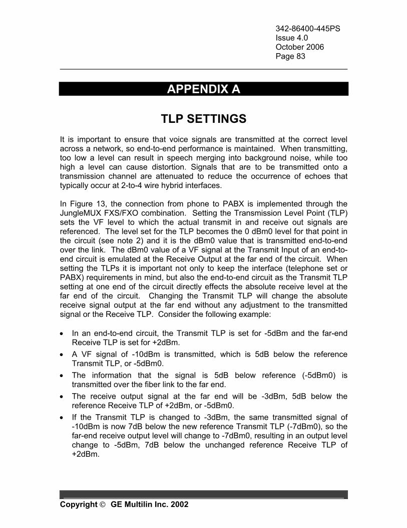
342-86400-445PS Issue 4.0 October 2006 Page 83
Copyright GE Multilin Inc. 2002
APPENDIX A
TLP SETTINGS It is important to ensure that voice signals are transmitted at the correct level across a network, so end-to-end performance is maintained. When transmitting, too low a level can result in speech merging into background noise, while too high a level can cause distortion. Signals that are to be transmitted onto a transmission channel are attenuated to reduce the occurrence of echoes that typically occur at 2-to-4 wire hybrid interfaces. In Figure 13, the connection from phone to PABX is implemented through the JungleMUX FXS/FXO combination. Setting the Transmission Level Point (TLP) sets the VF level to which the actual transmit in and receive out signals are referenced. The level set for the TLP becomes the 0 dBm0 level for that point in the circuit (see note 2) and it is the dBm0 value that is transmitted end-to-end over the link. The dBm0 value of a VF signal at the Transmit Input of an end-to-end circuit is emulated at the Receive Output at the far end of the circuit. When setting the TLPs it is important not only to keep the interface (telephone set or PABX) requirements in mind, but also the end-to-end circuit as the Transmit TLP setting at one end of the circuit directly effects the absolute receive level at the far end of the circuit. Changing the Transmit TLP will change the absolute receive signal output at the far end without any adjustment to the transmitted signal or the Receive TLP. Consider the following example: • In an end-to-end circuit, the Transmit TLP is set for -5dBm and the far-end
Receive TLP is set for +2dBm. • A VF signal of -10dBm is transmitted, which is 5dB below the reference
Transmit TLP, or -5dBm0. • The information that the signal is 5dB below reference (-5dBm0) is
transmitted over the fiber link to the far end. • The receive output signal at the far end will be -3dBm, 5dB below the
reference Receive TLP of +2dBm, or -5dBm0. • If the Transmit TLP is changed to -3dBm, the same transmitted signal of
-10dBm is now 7dB below the new reference Transmit TLP (-7dBm0), so the far-end receive output level will change to -7dBm0, resulting in an output level change to -5dBm, 7dB below the unchanged reference Receive TLP of +2dBm.
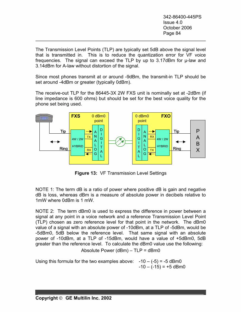
342-86400-445PS Issue 4.0 October 2006 Page 84
Copyright GE Multilin Inc. 2002
The Transmission Level Points (TLP) are typically set 5dB above the signal level that is transmitted in. This is to reduce the quantization error for VF voice frequencies. The signal can exceed the TLP by up to 3.17dBm for µ-law and 3.14dBm for A-law without distortion of the signal. Since most phones transmit at or around -9dBm, the transmit-in TLP should be set around -4dBm or greater (typically 0dBm). The receive-out TLP for the 86445-3X 2W FXS unit is nominally set at -2dBm (if line impedance is 600 ohms) but should be set for the best voice quality for the phone set being used.
Tip
Ring
0 dBm0point
TX
RX
FXS
TX
RX
0 dBm0point
ANALOG
DIGITAL
ANALOG
DIGITAL
Tip
Ring
FXO
4W / 2W
HYBRID
4W / 2W
HYBRID
PABX
Tip
Ring
0 dBm0point
TX
RX
FXS
TX
RX
0 dBm0point
ANALOG
DIGITAL
ANALOG
DIGITAL
Tip
Ring
FXO
4W / 2W
HYBRID
4W / 2W
HYBRID
PABX
Figure 13: VF Transmission Level Settings NOTE 1: The term dB is a ratio of power where positive dB is gain and negative dB is loss, whereas dBm is a measure of absolute power in decibels relative to 1mW where 0dBm is 1 mW. NOTE 2: The term dBm0 is used to express the difference in power between a signal at any point in a voice network and a reference Transmission Level Point (TLP) chosen as zero reference level for that point in the network. The dBm0 value of a signal with an absolute power of -10dBm, at a TLP of -5dBm, would be -5dBm0, 5dB below the reference level. That same signal with an absolute power of -10dBm, at a TLP of -15dBm, would have a value of +5dBm0, 5dB greater than the reference level. To calculate the dBm0 value use the following:
Absolute Power (dBm) – TLP = dBm0 Using this formula for the two examples above: -10 – (-5) = -5 dBm0 -10 – (-15) = +5 dBm0
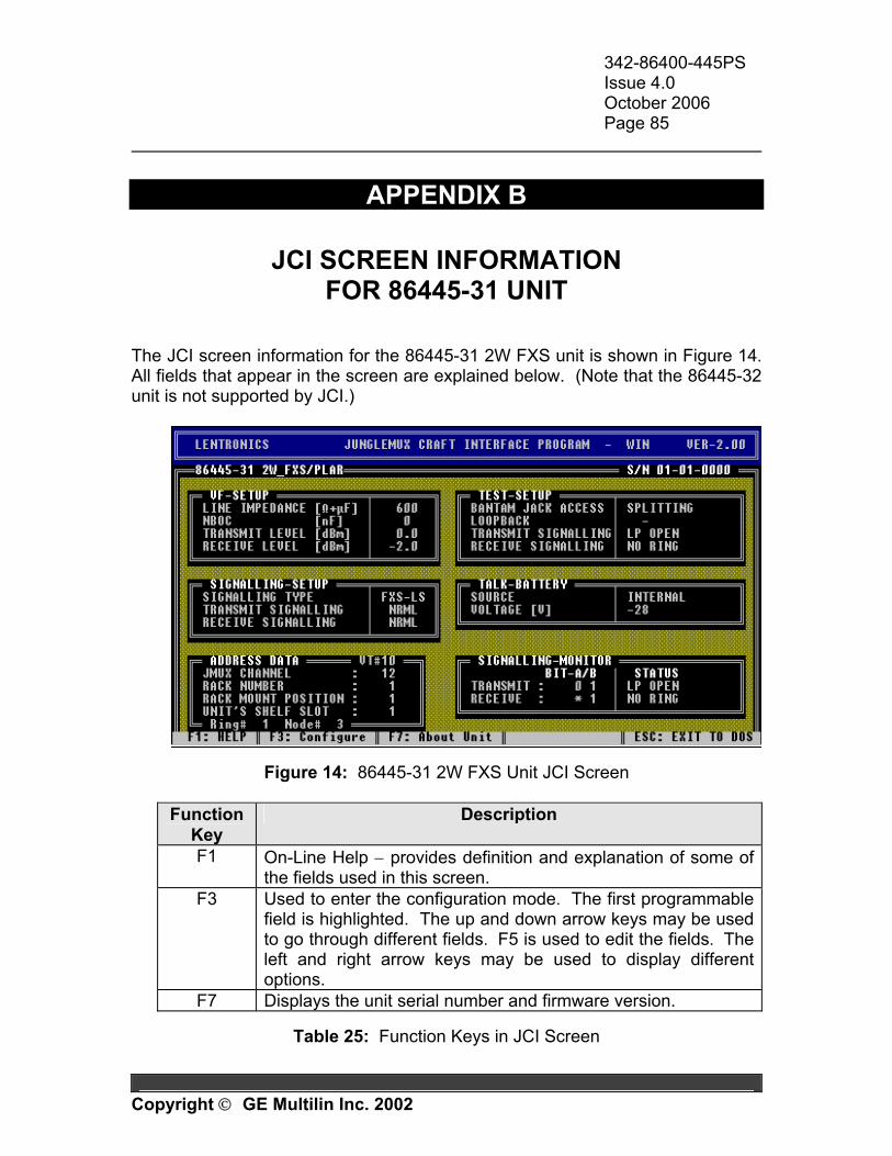
342-86400-445PS Issue 4.0 October 2006 Page 85
Copyright GE Multilin Inc. 2002
APPENDIX B
JCI SCREEN INFORMATION FOR 86445-31 UNIT
The JCI screen information for the 86445-31 2W FXS unit is shown in Figure 14. All fields that appear in the screen are explained below. (Note that the 86445-32 unit is not supported by JCI.)
Figure 14: 86445-31 2W FXS Unit JCI Screen
Function Key
Description
F1 On-Line Help − provides definition and explanation of some of the fields used in this screen.
F3 Used to enter the configuration mode. The first programmable field is highlighted. The up and down arrow keys may be used to go through different fields. F5 is used to edit the fields. The left and right arrow keys may be used to display different options.
F7 Displays the unit serial number and firmware version.
Table 25: Function Keys in JCI Screen
342-86400-445PS Issue 4.0 October 2006 Page 86
Copyright GE Multilin Inc. 2002
VF Setup LINE IMPEDANCE
May be set to either 600 Ω or 900 Ω in series with or without 2.15 µF of line capacitance. This impedance must also be hardware strapped on the main assembly board.
Note: The selection made in this field must match the respective strapping selection made on the unit's main assembly board. Note: It is important to match the actual line impedance with the 2W FXS unit's input impedance to maximize the amount of power to be transferred from the telephone to the line. Impedance mismatches create side tones which in the worst case are perceived as echoes. The addition of 2.15µF adds capacitive reactance to the line that may reduce noise and distortion.
NBOC
Selectable to 0, 22, 47 or 69 nF. This may be used for additional line capacitance compensation. NBOC must also be hardware strapped on the main assembly board.
Note: The selection made in this field must match the respective strapping selection made on the unit's main assembly board. Note: Network build-out capacitance is added to provide additional line balancing. Generally, no additional NBOC is required for lines shorter than 2000 ft (600 m).
TRANSMIT LEVEL [dBm]
Software selectable from -14.0 to +6.0 dBm in 0.1 dB increments. Default is 0 dBm.
Note: The Line Impedance parameter shall be set before Transmit Level because any subsequent changes to the Line Impedance setting may also alter the Transmit Level setting.
RECEIVE LEVEL [dBm]
Software selectable from -15.0 to +5.0 dBm in 0.1 dB increments. Default is -2 dBm.
Note: The Line Impedance parameter shall be set before Receive Level because any subsequent changes to the Line Impedance setting may also alter the Receive Level setting.
342-86400-445PS Issue 4.0 October 2006 Page 87
Copyright GE Multilin Inc. 2002
Signalling Setup SIGNALLING TYPE
May be set to Loop Start (LS), Ground Start (GS) or Private Line Automatic Ringdown (PLAR). The far-end unit interface must be set for the same signaling type.
Note: Although the 2W FXS unit is normally used with either 86445-41 2W FXO unit (for LS and GS applications) or 86445-3X 2W FXS unit (for PLAR application) at the far end, it can also be used with 86444 4W VF unit when no signaling is required. This may be utilized for VF channel testing.
TRANSMIT SIGNALLING
May be either NRML (normal) or TEST. In TEST mode the transmit signaling bits can be forced to any condition (whether valid or not for selected signaling type) using the TRANSMIT SIGNALLING field in the TEST SETUP window. The selected transmit test signaling status will also be displayed in the SIGNALLING MONITOR window.
Note: This field must be set to NRML when not being used for test or maintenance purposes.
RECEIVE SIGNALLING
May be either NRML (normal) or TEST. In TEST mode the receive signaling bits can be forced to any condition (whether valid or not for selected signaling type) using the RECEIVE SIGNALLING field in the TEST SETUP window. The selected receive test signaling status will also be displayed in the SIGNALLING-MONITOR window.
Note: This field must be set to NRML when not being used for test or maintenance purposes.
Address Data VT# (Not Adjustable)
Displays the VT# feeding the JVT bus that the unit is on.
Note: If this field is not displayed, the NMS communication with the respective JIF-Share unit is not established.
342-86400-445PS Issue 4.0 October 2006 Page 88
Copyright GE Multilin Inc. 2002
Note: At an OC-N (N>1) node, the VT# may not indicate the actual VT position in the OC-N signal. To find out which VT in the OC-N signal corresponds to the displayed VT#, the user must refer to the OC-N JMUX unit's TSI/CC information screen.
JMUX CHANNEL
Allows DS0 channel assignment to the unit. Channel number is selectable from 1 to 24. A ‘-‘ (default selection) indicates that a channel has not been assigned. Each channel occupies its own DS0 (64 kb/s) time slot on the JVT. Ensure that the channel assigned on this unit is not assigned on any other DS0 level unit on the same JVT. The corresponding far-end unit must be given the same channel assignment.
RACK NUMBER (use is optional) Identifies the rack or cabinet (1 to 64) in which the unit is located. This information may be utilized on the NMS (Network Management System).
RACK MOUNT POSITION (use is optional)
Identifies the shelf (1 to 64) in which the unit is located. This information may be utilized on the NMS.
UNIT'S SHELF SLOT (use is optional) Identifies the slot position within the shelf (1 to 15) in which the unit is located. This information may be utilized on the NMS.
Ring # and Node # (Not Adjustable) Displays the Ring # and Node # this unit is on.
Test Setup BANTAM JACK ACCESS
May be set for Bridging or Splitting (default). Bridging mode allows for monitoring of the circuit via bantam jacks on the unit face plate. Splitting mode disconnects the drop side of the circuit (upon insertion of test jack) and allows tones to be injected and measured for end-to-end or loopback testing.
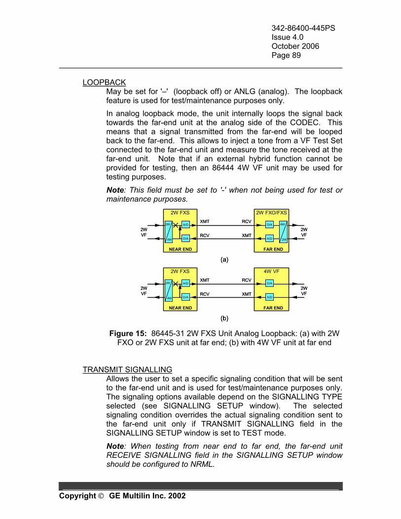
342-86400-445PS Issue 4.0 October 2006 Page 89
Copyright GE Multilin Inc. 2002
LOOPBACK
May be set for '–' (loopback off) or ANLG (analog). The loopback feature is used for test/maintenance purposes only. In analog loopback mode, the unit internally loops the signal back towards the far-end unit at the analog side of the CODEC. This means that a signal transmitted from the far-end will be looped back to the far-end. This allows to inject a tone from a VF Test Set connected to the far-end unit and measure the tone received at the far-end unit. Note that if an external hybrid function cannot be provided for testing, then an 86444 4W VF unit may be used for testing purposes.
Note: This field must be set to '-' when not being used for test or maintenance purposes.
RCV
XMT
2W FXS 2W FXO/FXS
2W
4W
XMT
RCV
4W
2W
2WVF
2WVF
NEAR END FAR END
A/D
D/A
D/A
A/D
(a)
RCV
XMT
2W FXS 4W VF
2W
4W
XMT
RCV2WVF
2WVF
NEAR END FAR END
A/D
D/A
D/A
A/D
(b)
RCV
XMT
2W FXS 2W FXO/FXS
2W
4W
2W
4W
XMT
RCV
4W
2W
4W
2W
2WVF
2WVF
NEAR END FAR END
A/D
D/A
D/A
A/D
(a)
RCV
XMT
2W FXS 4W VF
2W
4W
2W
4W
XMT
RCV2WVF
2WVF
NEAR END FAR END
A/D
D/A
D/A
A/D
(b) Figure 15: 86445-31 2W FXS Unit Analog Loopback: (a) with 2W
FXO or 2W FXS unit at far end; (b) with 4W VF unit at far end
TRANSMIT SIGNALLING Allows the user to set a specific signaling condition that will be sent to the far-end unit and is used for test/maintenance purposes only. The signaling options available depend on the SIGNALLING TYPE selected (see SIGNALLING SETUP window). The selected signaling condition overrides the actual signaling condition sent to the far-end unit only if TRANSMIT SIGNALLING field in the SIGNALLING SETUP window is set to TEST mode.
Note: When testing from near end to far end, the far-end unit RECEIVE SIGNALLING field in the SIGNALLING SETUP window should be configured to NRML.

342-86400-445PS Issue 4.0 October 2006 Page 90
Copyright GE Multilin Inc. 2002
Note: The unit's yellow (BUSY) LED illuminates only if an OFF-HOOK condition is initiated from an external source (i.e. signaling test set or telephone). Note: The signaling information is mapped into two bits of the PSFR byte (part of VT1.5 frame). There are four possible transmit signaling combinations that can be addressed by these bits: 00, 01, 10, and 11 and some of them are not used. When a NOT VALID signaling condition (combination of the two bits) is selected, the unit will send the selected combination even though it does not apply to any valid signaling condition for the Signalling Type chosen.
RECEIVE SIGNALLING Allows the user to set a specific signaling condition that will be sent to the local drop equipment and is used for test/maintenance purposes only. The options available depend on the Signalling Type selected (see Signalling Setup window). The selected signaling condition overrides the actual signaling condition received from the far-end unit only if RECEIVE SIGNALLING field in the SIGNALLING SETUP window is set to TEST mode.
Talk Battery and Ringing Generator SOURCE (Not Adjustable)
Displays INTERNAL. VOLTAGE [V]
Selectable for -28 or -56 V. This is the talk battery voltage that this unit's sub-board will provide to the line (if installed).
Note: On units configured for 600Ω resistive only, it is recommended that -56 VDC not be used.
RING CADENCE TYPE (Available in PLAR mode only)
Sets the type of ringing produced when in PLAR mode. May be set to NORTH AMERICAN, EUROPEAN or STEADY.
Note: This field is displayed only if PLAR is selected in the SIGNALLING TYPE field (SIGNALLING SETUP window) and the unit's Micro code is version 2.5 or later.
342-86400-445PS Issue 4.0 October 2006 Page 91
Copyright GE Multilin Inc. 2002
RING DURATION (Available in PLAR mode only)
Sets the ringing duration when in PLAR mode. May be set to 10 sec, 20 sec, 60 sec and Indefinite.
Note: This field is displayed only if PLAR is selected in the SIGNALLING TYPE field (SIGNALLING SETUP window) and the unit's Micro code is version 2.5 or later. Note: In the Loop Start (LS) and Ground Start (GS) signaling modes the ringing duration is not limited.
Signalling Monitor TRANSMIT (Not Adjustable)
Shows current signaling status sent towards the far-end unit. When TRANSMIT SIGNALLING (SIGNALLING SETUP window) is in TEST mode, the transmit signaling condition set in the TEST SETUP window is displayed. When TRANSMIT SIGNALLING (SIGNALLING SETUP) is in NRML mode, the transmit signaling condition set in TEST SETUP window is ignored and the SIGNALLING MONITOR will display the current signaling condition from the drop equipment. A and B refers to the status of the encoded signaling bits (ONE or ZERO) in the PSFR byte (part of VT1.5 frame).
Note: When a NOT VALID signaling condition (i.e. combination of the two signaling bits) is selected in the TRANSMIT SIGNALLING field (TEST SETUP frame), the unit will send the selected combination even though it does not apply to any valid signaling condition for the Signalling Type chosen.
RECEIVE (Not Adjustable) Shows current signaling status received from the far-end unit. When RECEIVE SIGNALLING (SIGNALLING SETUP window) is in TEST mode, the signaling status received from the far-end unit is overridden and the receive signaling condition set in the TEST SETUP window is displayed. The receive monitor will display one of the four transmit signaling combinations (from the far end) or it may display "∗" either instead of A or instead of B bit. This denotes a variable condition at the receive end, i.e. ON-HOOK or OFF-HOOK where the "∗" bit may be either '1' or '0'.
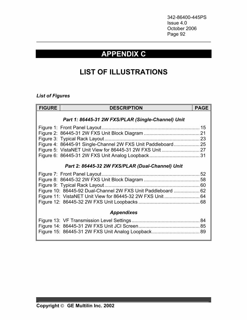
342-86400-445PS Issue 4.0 October 2006 Page 92
Copyright GE Multilin Inc. 2002
APPENDIX C
LIST OF ILLUSTRATIONS List of Figures FIGURE DESCRIPTION PAGE
Part 1: 86445-31 2W FXS/PLAR (Single-Channel) Unit Figure 1: Front Panel Layout ........................................................................ 15 Figure 2: 86445-31 2W FXS Unit Block Diagram ......................................... 21 Figure 3: Typical Rack Layout ...................................................................... 23 Figure 4: 86445-91 Single-Channel 2W FXS Unit Paddleboard................... 25 Figure 5: VistaNET Unit View for 86445-31 2W FXS Unit ............................ 27 Figure 6: 86445-31 2W FXS Unit Analog Loopback..................................... 31
Part 2: 86445-32 2W FXS/PLAR (Dual-Channel) Unit Figure 7: Front Panel Layout ........................................................................ 52 Figure 8: 86445-32 2W FXS Unit Block Diagram ......................................... 58 Figure 9: Typical Rack Layout ...................................................................... 60 Figure 10: 86445-92 Dual-Channel 2W FXS Unit Paddleboard ................... 62 Figure 11: VistaNET Unit View for 86445-32 2W FXS Unit .......................... 64 Figure 12: 86445-32 2W FXS Unit Loopbacks ............................................. 68
Appendixes Figure 13: VF Transmission Level Settings .................................................. 84 Figure 14: 86445-31 2W FXS Unit JCI Screen............................................. 85 Figure 15: 86445-31 2W FXS Unit Analog Loopback................................... 89
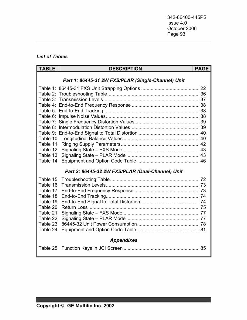
342-86400-445PS Issue 4.0 October 2006 Page 93
Copyright GE Multilin Inc. 2002
List of Tables
TABLE DESCRIPTION PAGE
Part 1: 86445-31 2W FXS/PLAR (Single-Channel) Unit Table 1: 86445-31 FXS Unit Strapping Options ........................................... 22 Table 2: Troubleshooting Table.................................................................... 36 Table 3: Transmission Levels....................................................................... 37 Table 4: End-to-End Frequency Response .................................................. 38 Table 5: End-to-End Tracking ...................................................................... 38 Table 6: Impulse Noise Values..................................................................... 38 Table 7: Single Frequency Distortion Values................................................ 39 Table 8: Intermodulation Distortion Values................................................... 39 Table 9: End-to-End Signal to Total Distortion ............................................. 40 Table 10: Longitudinal Balance Values ........................................................ 40 Table 11: Ringing Supply Parameters.......................................................... 42 Table 12: Signaling State – FXS Mode ........................................................ 43 Table 13: Signaling State – PLAR Mode ...................................................... 43 Table 14: Equipment and Option Code Table .............................................. 46
Part 2: 86445-32 2W FXS/PLAR (Dual-Channel) Unit Table 15: Troubleshooting Table.................................................................. 72 Table 16: Transmission Levels..................................................................... 73 Table 17: End-to-End Frequency Response ................................................ 73 Table 18: End-to-End Tracking..................................................................... 74 Table 19: End-to-End Signal to Total Distortion ........................................... 74 Table 20: Return Loss .................................................................................. 75 Table 21: Signaling State – FXS Mode ........................................................ 77 Table 22: Signaling State – PLAR Mode ...................................................... 77 Table 23: 86445-32 Unit Power Consumption.............................................. 78 Table 24: Equipment and Option Code Table .............................................. 81
Appendixes Table 25: Function Keys in JCI Screen ........................................................ 85

342-86400-445PS Issue 4.0 October 2006 Page 94
Copyright GE Multilin Inc. 2002
APPENDIX D
LIST OF ACRONYMS
• 2W 2-Wire • 4W 4-Wire • ACK Acknowledge • A-D Analog to Digital • ANLG Analog • ANSI American National Standards Institute • BRDG Bridging • CBW Configurable Bandwidth • CC Cross-Connect • CH Channel • CI Craft Interface • CO Central Office • CODEC Coder/Decoder • COM Communication • CPU Central Processing Unit • D-A Digital to Analog • DC Direct Current • DOS Disk Operating System • DS0 Digital Signal – Level 0 (64 kb/s) • EAS Equipment Assembly Schematic • EEPROM Electronically Erasable and Programmable ROM • EIA Electronic Industries Association • EMI Electromagnetic Interference • ESDS Electrostatic Discharge Sensitive • FPGA Field Programmable Gate Array • FXO Foreign Exchange Office • FXS Foreign Exchange Station • GS Ground Start (Signaling Mode) • IEEE Institute of Electrical and Electronics Engineers • JCI JungleMUX Craft Interface • JIF JungleMUX Intermediate Format • JMUX JungleMUX
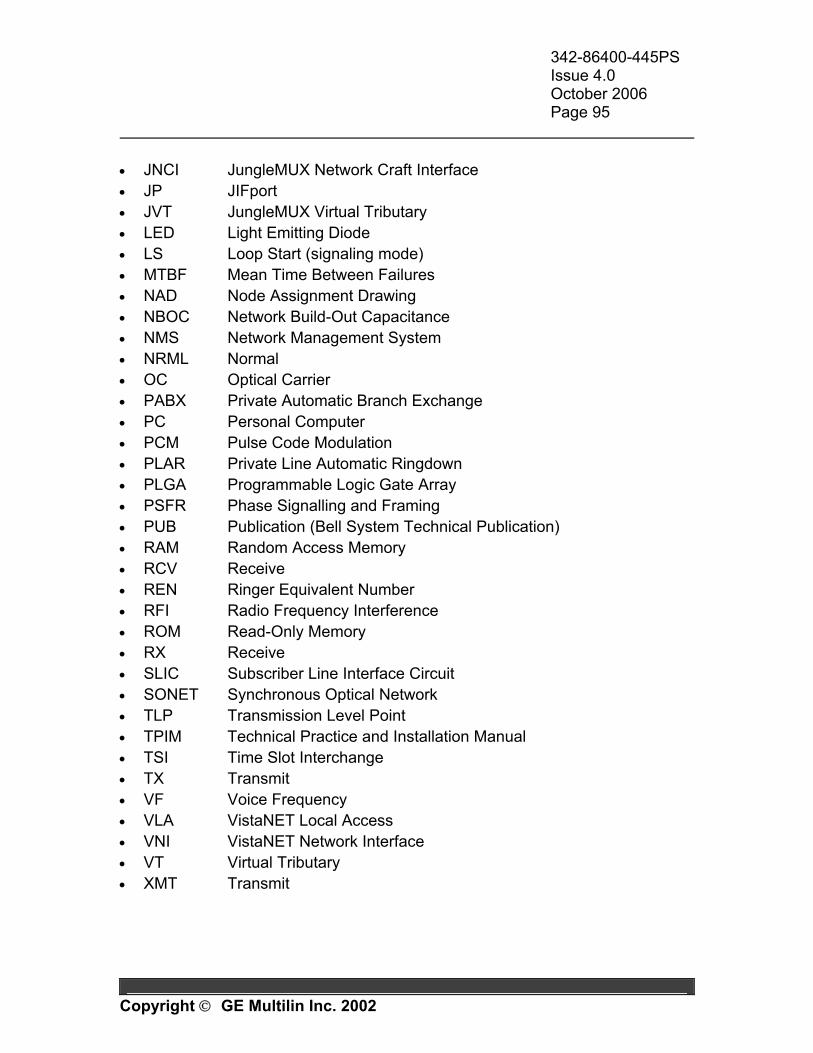
342-86400-445PS Issue 4.0 October 2006 Page 95
Copyright GE Multilin Inc. 2002
• JNCI JungleMUX Network Craft Interface • JP JIFport • JVT JungleMUX Virtual Tributary • LED Light Emitting Diode • LS Loop Start (signaling mode) • MTBF Mean Time Between Failures • NAD Node Assignment Drawing • NBOC Network Build-Out Capacitance • NMS Network Management System • NRML Normal • OC Optical Carrier • PABX Private Automatic Branch Exchange • PC Personal Computer • PCM Pulse Code Modulation • PLAR Private Line Automatic Ringdown • PLGA Programmable Logic Gate Array • PSFR Phase Signalling and Framing • PUB Publication (Bell System Technical Publication) • RAM Random Access Memory • RCV Receive • REN Ringer Equivalent Number • RFI Radio Frequency Interference • ROM Read-Only Memory • RX Receive • SLIC Subscriber Line Interface Circuit • SONET Synchronous Optical Network • TLP Transmission Level Point • TPIM Technical Practice and Installation Manual • TSI Time Slot Interchange • TX Transmit • VF Voice Frequency • VLA VistaNET Local Access • VNI VistaNET Network Interface • VT Virtual Tributary • XMT Transmit