Embed Size (px)
Citation preview

PARTS AND OPERATION MANUALOPERATION AND PARTS MANUAL
PARTS LIST NO. M1871400004B
Revision #2 (04/22/05)
DCA-45USIULTRA-SILENTTM SERIES
GENERATOR
THIS MANUAL MUST ACCOMPANYTHE EQUIPMENT AT ALL TIMES.
PAGE 2 — DCA-45USI — OPERATION AND PARTS MANUAL (STD) — REV. #2 (04/22/05)
DCA-45USI — OPERATION AND PARTS MANUAL (STD) — REV. #2 (04/22/05) — PAGE 3
© COPYRIGHT 2004, MULTIQUIP INC.
Multiquip Inc, MQ Power Inc, Ultra-Silent series, the MQ logo and the MQ Power logo are registered trademarks of Multiquip Inc. andmay not be used, reproduced, or altered without written permission. All other trademarks are the property of thier respective ownersand used with permission.
This manual MUST accompany the equipment at all times. This manual is considered a permanent part of the equipment andshould remain with the unit if resold.
The information and specifications included in this publication were in effect at the time of approval for printing. Illustrations arebased on the DCA-45USI Ultra Silent Generator. Multiquip Inc. reserves the right to discontinue or change specifications, design orthe information published in this publication at any time without notice and without incurring any obligations.
To find the latest revision of thispublication, visit our website at:
www.mqpower.com
HERE'S HOW TO GET HELPPLEASE HAVE THE MODEL AND SERIAL
NUMBER ON-HAND WHEN CALLINGMQ POWER CORPORATE OFFICE18910 Wilmington Ave. 800-421-1244Carson, CA 90746 FAX: 310-632-2656Email: [email protected]: www.mqpower.comPARTS DEPARTMENT800-427-1244 FAX: 800-672-7877310-537-3700 FAX: 310-637-3284SERVICE DEPARTMENT800-835-2551 FAX: 310-638-8046310-537-3700TECHNICAL ASSISTANCE800-478-1244 FAX: 310-631-5032WARRANTY DEPARTMENT800-835-2551, EXT. 279 FAX: 310-638-8046310-537-3700, EXT. 279

PAGE 4 — DCA-45USI — OPERATION AND PARTS MANUAL (STD) — REV. #2 (04/22/05)
TABLE OF CONTENTS
MQ POWER DCA-45USIMQ POWER DCA-45USIMQ POWER DCA-45USIMQ POWER DCA-45USIMQ POWER DCA-45USIAC GENERAAC GENERAAC GENERAAC GENERAAC GENERATORTORTORTORTORHere's How To Get Help ............................................. 3Table Of Contents ....................................................... 4Parts Ordering Procedures ........................................ 5DCA-45USI Specifications .......................................... 6Dimensions .................................................................. 7Safety Message Alert Symbols ............................... 8-9Rules for Safe Operation ..................................... 10-13Installation ............................................................ 14-15Towing Safety Precautions ....................................... 16Trailer Specifications ................................................. 17Generator Decals ................................................. 18-19General Information .................................................. 20Major Components ................................................... 21Generator Control Panel ........................................... 22Engine Operating Panel ............................................ 23Output Terminal Panel Familiarization ................. 24-26Load Application........................................................ 27Generator Outputs ............................................... 28-29Gauge Reading ......................................................... 30Output Terminal Panel Connections .................... 30-31Pre-setup .............................................................. 32-35Generator Start-up Procedure ............................ 36-38Generator Shut-down Procedure ............................. 39Maintenance ......................................................... 40-41Trailer Brakes Maintenance ...................................... 42Trailer Maintenance ............................................. 43-44Trailer Wiring Diagram .............................................. 45Engine Wiring Diagram ........................................ 46-47Generator Wiring Diagram ....................................... 48Generator Troubleshooting ....................................... 49Explanation of Codes in Remarks Column .............. 50Suggested Spare Parts ............................................ 51
Specification and part numberare subject to change withoutnotice.
NOTE
COMPONENT DRACOMPONENT DRACOMPONENT DRACOMPONENT DRACOMPONENT DRAWINGSWINGSWINGSWINGSWINGSGenerator Assembly ............................................ 52-53Control Box Assembly .......................................... 54-57Engine & Radiator Assembly ............................... 58-61Output Terminal Assembly ................................... 62-63Battery Assembly ................................................. 64-65Muffler Assembly ................................................. 66-67Fuel Tank Assembly ............................................. 68-69Enclosure Assembly ............................................ 70-75Rubber Seal Assembly ........................................ 76-77Nameplate and Decals ........................................ 78-79
Terms and Condition of Sale — Parts ...................... 80
DCA-45USI — OPERATION AND PARTS MANUAL (STD) — REV. #2 (04/22/05) — PAGE 5
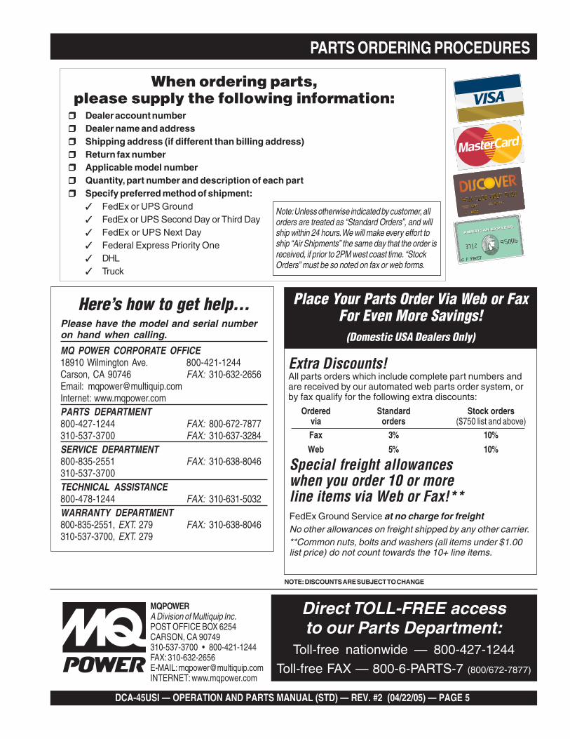
PARTS ORDERING PROCEDURES
MQPOWERA Division of Multiquip Inc.POST OFFICE BOX 6254CARSON, CA 90749310-537-3700 • 800-421-1244FAX: 310-632-2656E-MAIL: [email protected]: www.mqpower.com
When ordering parts,please supply the following information:
❒❒❒❒❒ Dealer account number❒❒❒❒❒ Dealer name and address❒❒❒❒❒ Shipping address (if different than billing address)❒❒❒❒❒ Return fax number❒❒❒❒❒ Applicable model number❒❒❒❒❒ Quantity, part number and description of each part❒❒❒❒❒ Specify preferred method of shipment:
✓ FedEx or UPS Ground✓ FedEx or UPS Second Day or Third Day✓ FedEx or UPS Next Day✓ Federal Express Priority One✓ DHL✓ Truck
Note: Unless otherwise indicated by customer, allorders are treated as “Standard Orders”, and willship within 24 hours. We will make every effort toship “Air Shipments” the same day that the order isreceived, if prior to 2PM west coast time. “StockOrders” must be so noted on fax or web forms.
Extra Discounts!All parts orders which include complete part numbers andare received by our automated web parts order system, orby fax qualify for the following extra discounts:
Ordered Standard Stock ordersvia orders ($750 list and above)
Fax 3% 10%
Web 5% 10%
Special freight allowanceswhen you order 10 or moreline items via Web or Fax!**FedEx Ground Service at no charge for freightNo other allowances on freight shipped by any other carrier.**Common nuts, bolts and washers (all items under $1.00list price) do not count towards the 10+ line items.
Place Your Parts Order Via Web or FaxFor Even More Savings!
(Domestic USA Dealers Only)
NOTE: DISCOUNTS ARE SUBJECT TO CHANGE
Here’s how to get help...Please have the model and serial numberon hand when calling.
MQ POWER CORPORATE OFFICE18910 Wilmington Ave. 800-421-1244Carson, CA 90746 FAX: 310-632-2656Email: [email protected]: www.mqpower.comPARTS DEPARTMENT800-427-1244 FAX: 800-672-7877310-537-3700 FAX: 310-637-3284SERVICE DEPARTMENT800-835-2551 FAX: 310-638-8046310-537-3700TECHNICAL ASSISTANCE800-478-1244 FAX: 310-631-5032WARRANTY DEPARTMENT800-835-2551, EXT. 279 FAX: 310-638-8046310-537-3700, EXT. 279
Direct TOLL-FREE accessto our Parts Department:
Toll-free nationwide — 800-427-1244
Toll-free FAX — 800-6-PARTS-7 (800/672-7877)
PAGE 6 — DCA-45USI — OPERATION AND PARTS MANUAL (STD) — REV. #2 (04/22/05)
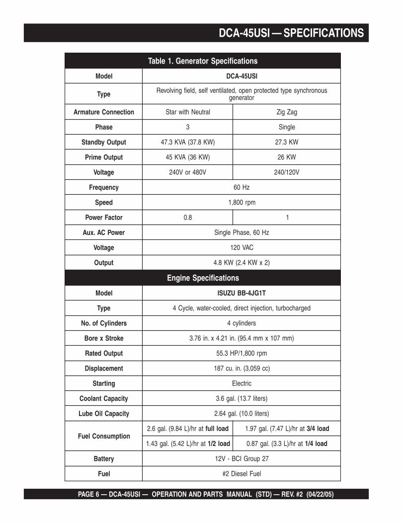
DCA-45USI — SPECIFICATIONS
snoitacificepSrotareneG.1elbaT
ledoM ISU54-ACD
epyT suonorhcnysepytdetcetorpnepo,detalitnevfles,dleifgnivloveRrotareneg
noitcennoCerutamrA lartueNhtiwratS gaZgiZ
esahP 3 elgniS
tuptuOybdnatS )WK8.73(AVK3.74 WK3.72
tuptuOemirP )WK63(AVK54 WK62
egatloV V084roV042 V021/042
ycneuqerF zH06
deepS mpr008,1
rotcaFrewoP 8.0 1
rewoPCA.xuA zH06,esahPelgniS
egatloV CAV021
tuptuO )2xWK4.2(WK8.4
snoitacificepSenignE
ledoM T1GJ4-BBUZUSI
epyT degrahcobrut,noitcejnitcerid,delooc-retaw,elcyC4
srednilyCfo.oN srednilyc4
ekortSxeroB )mm701xmm4.59(.ni12.4x.ni67.3
tuptuOdetaR mpr008,1/PH3.55
tnemecalpsiD )cc950,3(.ni.uc781
gnitratS cirtcelE
yticapaCtnalooC )sretil7.31(.lag6.3
yticapaCliOebuL )sretil0.01(.lag46.2
noitpmusnoCleuFtarh/)L48.9(.lag6.2 daollluf tarh/)L74.7(.lag79.1 daol4/3
tarh/)L24.5(.lag34.1 daol2/1 tarh/)L3.3(.lag78.0 daol4/1
yrettaB 72puorGICB-V21
leuF leuFleseiD2#
DCA-45USI — OPERATION AND PARTS MANUAL (STD) — REV. #2 (04/22/05) — PAGE 7
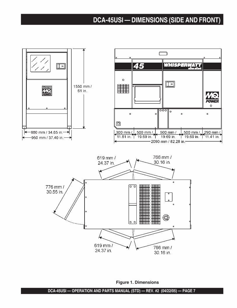
DCA-45USI — DIMENSIONS (SIDE AND FRONT)
Figure 1. Dimensions
PAGE 8 — DCA-45USI — OPERATION AND PARTS MANUAL (STD) — REV. #2 (04/22/05)
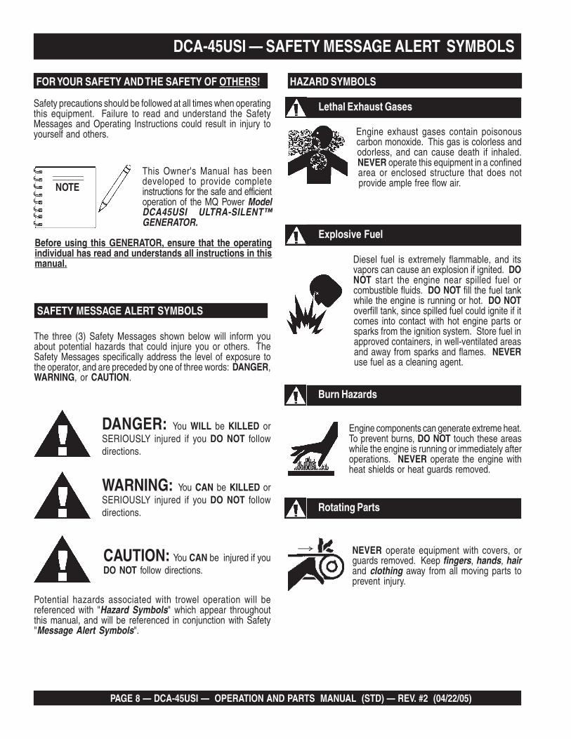
DCA-45USI — SAFETY MESSAGE ALERT SYMBOLS
This Owner's Manual has beendeveloped to provide completeinstructions for the safe and efficientoperation of the MQ Power ModelDCA45USI ULTRA-SILENT™GENERATOR.
Before using this GENERATOR, ensure that the operatingindividual has read and understands all instructions in thismanual.
Safety precautions should be followed at all times when operatingthis equipment. Failure to read and understand the SafetyMessages and Operating Instructions could result in injury toyourself and others.
FOR YOUR SAFETY AND THE SAFETY OF OTHERS!
SAFETY MESSAGE ALERT SYMBOLS
The three (3) Safety Messages shown below will inform youabout potential hazards that could injure you or others. TheSafety Messages specifically address the level of exposure tothe operator, and are preceded by one of three words: DANGER,WARNING, or CAUTION.
DANGER: You WILL be KILLED orSERIOUSLY injured if you DO NOT followdirections.
WARNING: You CAN be KILLED orSERIOUSLY injured if you DO NOT followdirections.
CAUTION: You CAN be injured if youDO NOT follow directions.
HAZARD SYMBOLS
Engine exhaust gases contain poisonouscarbon monoxide. This gas is colorless andodorless, and can cause death if inhaled.NEVER operate this equipment in a confinedarea or enclosed structure that does notprovide ample free flow air.
Potential hazards associated with trowel operation will bereferenced with "Hazard Symbols" which appear throughoutthis manual, and will be referenced in conjunction with Safety"Message Alert Symbols".
Diesel fuel is extremely flammable, and itsvapors can cause an explosion if ignited. DONOT start the engine near spilled fuel orcombustible fluids. DO NOT fill the fuel tankwhile the engine is running or hot. DO NOToverfill tank, since spilled fuel could ignite if itcomes into contact with hot engine parts orsparks from the ignition system. Store fuel inapproved containers, in well-ventilated areasand away from sparks and flames. NEVERuse fuel as a cleaning agent.
Burn Hazards
Engine components can generate extreme heat.To prevent burns, DO NOT touch these areaswhile the engine is running or immediately afteroperations. NEVER operate the engine withheat shields or heat guards removed.
Rotating Parts
NEVER operate equipment with covers, orguards removed. Keep fingers, hands, hairand clothing away from all moving parts toprevent injury.
Explosive Fuel
Lethal Exhaust Gases
NOTE
DCA-45USI — OPERATION AND PARTS MANUAL (STD) — REV. #2 (04/22/05) — PAGE 9
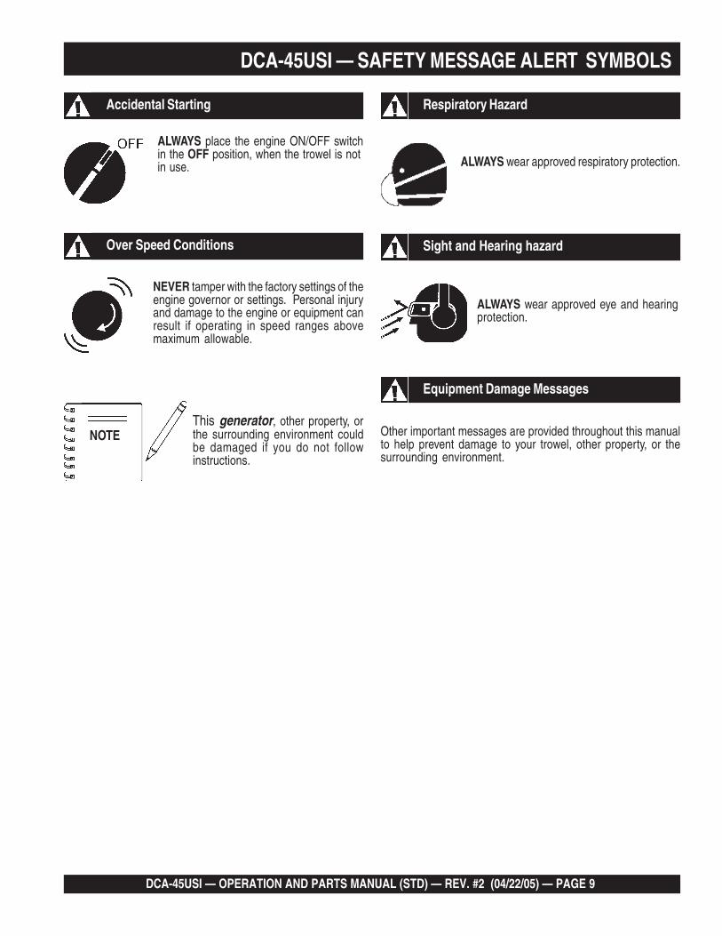
Accidental Starting
ALWAYS place the engine ON/OFF switchin the OFF position, when the trowel is notin use.
Over Speed Conditions
NEVER tamper with the factory settings of theengine governor or settings. Personal injuryand damage to the engine or equipment canresult if operating in speed ranges abovemaximum allowable.
Respiratory Hazard
ALWAYS wear approved respiratory protection.
ALWAYS wear approved eye and hearingprotection.
Sight and Hearing hazard
Equipment Damage Messages
Other important messages are provided throughout this manualto help prevent damage to your trowel, other property, or thesurrounding environment.
This generator, other property, orthe surrounding environment couldbe damaged if you do not followinstructions.
NOTE
DCA-45USI — SAFETY MESSAGE ALERT SYMBOLS
PAGE 10 — DCA-45USI — OPERATION AND PARTS MANUAL (STD) — REV. #2 (04/22/05)
DCA-45USI — RULES FOR SAFE OPERATION
CAUTIONCAUTIONCAUTIONCAUTIONCAUTION:Failure to follow instructions in this manual maylead to serious injury or even death! Thisequipment is to be operated by trained andqualified personnel only! This equipment isfor industrial use only.
The following safety guidelines should always be used whenoperating the DCA-45USI Generator:
GENERAL SAFETY
■ DO NOT operate or service this equipment beforereading this entire manual.
■ This equipment should not be operated by persons under 18years of age.
■ NEVER operate this equipment without properprotective clothing, shatterproof glasses, steel-toed boots and other protective devices requiredby the job.
■ NEVER operate this equipment when notfeeling well due to fatigue, illness or takingmedicine.
■ NEVER operate this equipment under theinfluence or drugs or alcohol.
■ NEVER use accessories or attachments, which are notrecommended by MQ Power for this equipment. Damage tothe equipment and/or injury to user may result.
■ Manufacture does not assume responsibility for any accidentdue to equipment modifications.
■ Whenever necessary, replace nameplate, operation andsafety decals when they become difficult read.
■ ALWAYS check the machine for loosened threads or boltsbefore starting.
■ NEVER operate the generator in an explosive atmosphere ornear combustible materials. An explosion or fire could resultcausing severe bodily harm or even death.
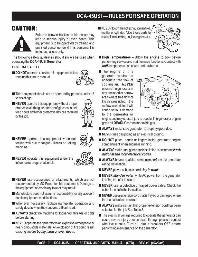
■ High Temperatures – Allow the engine to cool beforeperforming service and maintenance functions. Contact withhot! components can cause serious burns.
■ The engine of thisgenerator requires anadequate free flow ofcooling air. NEVERoperate the generator inany enclosed or narrowarea where free flow ofthe air is restricted. If theair flow is restricted it willcause serious damageto the generator orengine and may cause injury to people. The generator enginegives off DEADLY carbon monoxide gas.
■ ALWAYS make sure generator is properly grounded.
■ NEVER use gas piping as an electrical ground.
■ DO NOT place hands or fingers inside generator enginecompartment when engine is running.
■ ALWAYS make sure generator installation is accordance withnational and local electrical codes.
■ ALWAYS have a qualified electrician perform the generatorwiring installation.
■ NEVER power cables or cords lay in water.
■ NEVER stand in water while AC power from the generatoris being transfer to a load.
■ NEVER use a defective or frayed power cable. Check thecable for cuts in the insulation.
■ NEVER use a extension cord that is frayed or damaged wherethe insulation has been cut.
■ ALWAYS make certain that proper extension cord has beenselected for the job See Table 5.
■ The electrical voltage required to operate the generator cancause severe injury or even death through physical contactwith live circuits. Turn all circuit breakers OFF beforeperforming maintenance on the generator.
■ NEVER touch the hot exhaust manifold,muffler or cylinder. Allow these parts tocool before servicing engine or generator.

DCA-45USI — OPERATION AND PARTS MANUAL (STD) — REV. #2 (04/22/05) — PAGE 11
DCA-45USI — RULES FOR SAFE OPERATION
■ Backfeed to a utility system can cause electrocution and orproperty damage. DO NOT connect to any building's electricalsystem except through an approved device or after buildingmain switch is opened. ALWAYS have a licensed electricianperform the installation
CAUTIONCAUTIONCAUTIONCAUTIONCAUTION:DO NOT touch or open any of the belowmentioned components while thegenerator is running. Always allowsufficient time for the engine and generatorto cool before performing maintenance.
Radiator1. Radiator Cap - Removing the radiator cap while the engine
is hot will result in high pressurized, boiling water to gushout of the radiator, causing severe scalding to any personsin the general area of the generator.
2. Coolant Drain Plug - Removing the coolant drain plugwhile the engine is hot will result in hot coolant to gush outof the coolant drain plug, therefore causing severe scaldingto any persons in the general area of the generator.
3. Engine Oil Drain Plug - Removing the engine oil drainplug while the engine is hot will result in hot oil to gush outof the oil drain plug, therefore causing severe scalding toany persons in the general area of the generator.
DANGERDANGERDANGERDANGERDANGER:
DANGERDANGERDANGERDANGERDANGER:
■ NEVER touch output terminals during operation. This isextremely dangerous. ALWAYS stop the machine andplace the circuit breaker in the “OFF” position when contactwith the output terminals is required. There exists thepossibility of electrocution, electrical shock or burn,which can cause severe bodily harm or even death!
Never use damaged or worn cables whenconnecting equipment to the generator.Make sure powerc o n n e c t i n gcables are
securely connected to thegenerator’s output terminals,insufficient tightening of theterminal connections may causedamage to the generator andelectrical shock.
.
Maintenance Safety■ NEVER lubricate components or attempt
service on a running machine.
■ ALWAYS allow the machine a properamount of time to cool before servicing.
■ Keep the machinery in proper running condition.
■ Fix damage to the machine immediately and always replacebroken parts.
■ ALWAYS make sure that electrical circuits are properlygrounded per the National Electrical Code (NEC) and localcodes before operating generator. Severe injury or death! byelectrocution can result from operating an ungroundedgenerator.
■ ALWAYS be sure the operator is familiar with proper safetyprecautions and operations techniques before using generator.
■ ALWAYS store equipment properly when it is not being used.Equipment should be stored in a clean, dry location out of thereach of children.
■ ALWAYS read, understand, and followprocedures in Operator’s Manual beforeattempting to operate equipment.
DANGERDANGERDANGERDANGERDANGER:
DANGERDANGERDANGERDANGERDANGER:
POWERCORD
(POWER ON)
WETHANDS
NEVER grab ortouch a livepower cord withwet hands , thepossibility existsof electrical shock, electrocution, and evendeath!
PAGE 12 — DCA-45USI — OPERATION AND PARTS MANUAL (STD) — REV. #2 (04/22/05)
DCA-45USI — RULES FOR SAFE OPERATION
■ NEVER run engine without air filter. Severe engine damagemay occur.
■ ALWAYS service air cleaner frequently to prevent enginemalfunction.
■ ALWAYS disconnect the negative battery terminal beforeperforming service on the generator.
■ ALWAYS be sure the operator is familiar with proper safetyprecautions when operating the generator set.
■ ALWAYS store equipment properly when not in use.
■ DO NOT leave the generator running in the manual modeunattended.
■ DO NOT allow unauthorized people to operate thisequipment.
■ ALWAYS read, understand, and follow procedures inOperator’s Manual before attempting to operate equipment.
■ Refer to the Isuzu Engine Owner's Manual for enginetechnical questions or information.
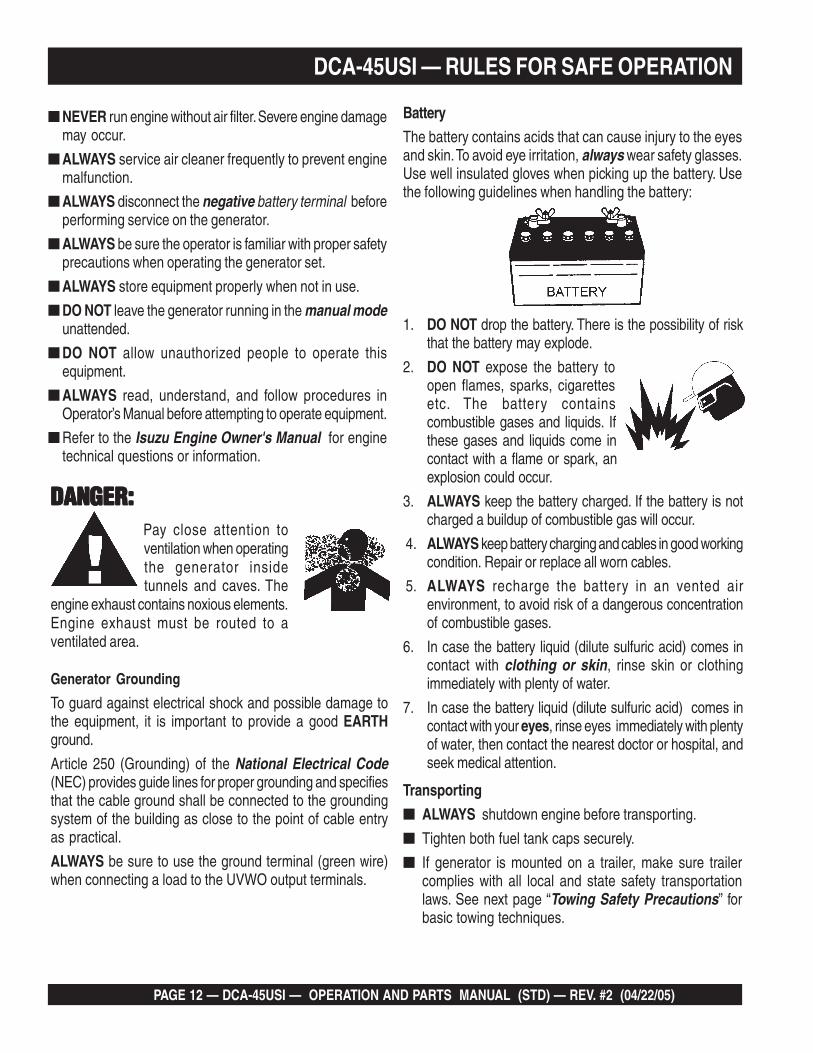
Battery
The battery contains acids that can cause injury to the eyesand skin. To avoid eye irritation, always wear safety glasses.Use well insulated gloves when picking up the battery. Usethe following guidelines when handling the battery:
1. DO NOT drop the battery. There is the possibility of riskthat the battery may explode.
2. DO NOT expose the battery toopen flames, sparks, cigarettesetc. The battery containscombustible gases and liquids. Ifthese gases and liquids come incontact with a flame or spark, anexplosion could occur.
3. ALWAYS keep the battery charged. If the battery is notcharged a buildup of combustible gas will occur.
4. ALWAYS keep battery charging and cables in good workingcondition. Repair or replace all worn cables.
5. ALWAYS recharge the battery in an vented airenvironment, to avoid risk of a dangerous concentrationof combustible gases.
6. In case the battery liquid (dilute sulfuric acid) comes incontact with clothing or skin, rinse skin or clothingimmediately with plenty of water.
7. In case the battery liquid (dilute sulfuric acid) comes incontact with your eyes, rinse eyes immediately with plentyof water, then contact the nearest doctor or hospital, andseek medical attention.
Pay close attention toventilation when operatingthe generator insidetunnels and caves. The
engine exhaust contains noxious elements.Engine exhaust must be routed to aventilated area.
DANGER:DANGER:DANGER:DANGER:DANGER:
Generator Grounding
To guard against electrical shock and possible damage tothe equipment, it is important to provide a good EARTHground.
Article 250 (Grounding) of the National Electrical Code(NEC) provides guide lines for proper grounding and specifiesthat the cable ground shall be connected to the groundingsystem of the building as close to the point of cable entryas practical.
ALWAYS be sure to use the ground terminal (green wire)when connecting a load to the UVWO output terminals.
Transporting
■ ALWAYS shutdown engine before transporting.
■ Tighten both fuel tank caps securely.
■ If generator is mounted on a trailer, make sure trailercomplies with all local and state safety transportationlaws. See next page “Towing Safety Precautions” forbasic towing techniques.
DCA-45USI — OPERATION AND PARTS MANUAL (STD) — REV. #2 (04/22/05) — PAGE 13
Emergencies
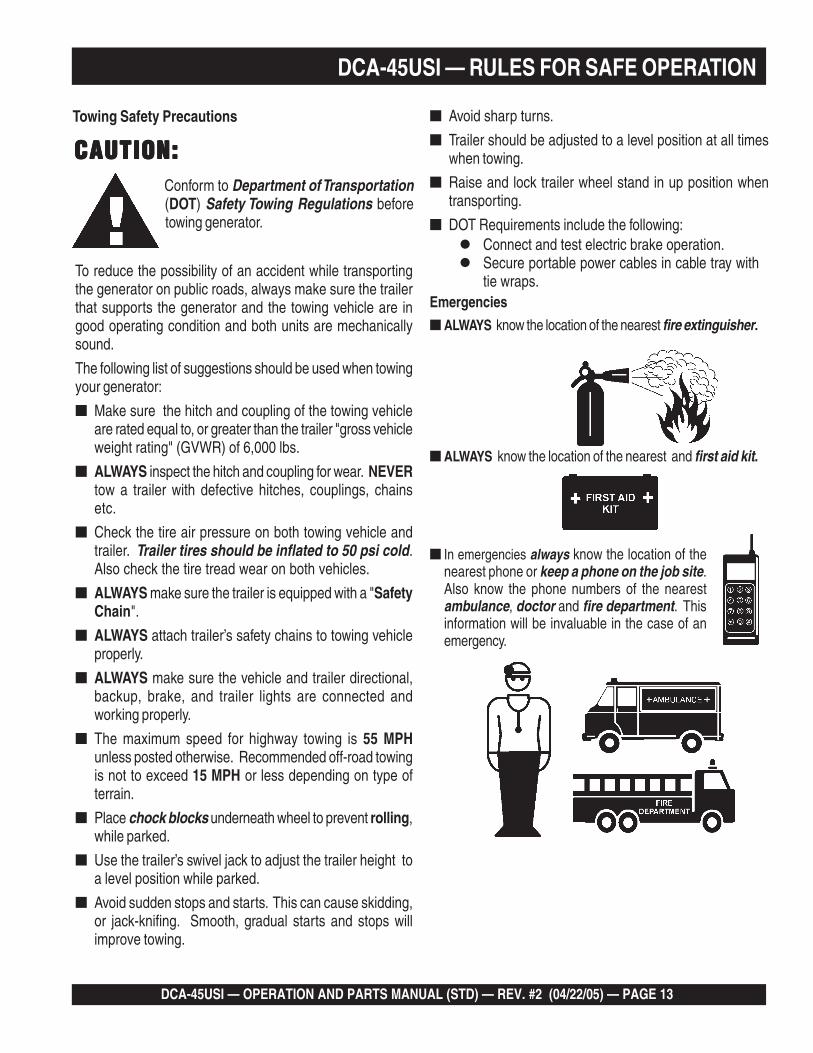
■ ALWAYS know the location of the nearest fire extinguisher.
■ ALWAYS know the location of the nearest and first aid kit.
■ In emergencies always know the location of thenearest phone or keep a phone on the job site.Also know the phone numbers of the nearestambulance, doctor and fire department. Thisinformation will be invaluable in the case of anemergency.
To reduce the possibility of an accident while transportingthe generator on public roads, always make sure the trailerthat supports the generator and the towing vehicle are ingood operating condition and both units are mechanicallysound.
The following list of suggestions should be used when towingyour generator:
■ Make sure the hitch and coupling of the towing vehicleare rated equal to, or greater than the trailer "gross vehicleweight rating" (GVWR) of 6,000 lbs.
■ ALWAYS inspect the hitch and coupling for wear. NEVERtow a trailer with defective hitches, couplings, chainsetc.
■ Check the tire air pressure on both towing vehicle andtrailer. Trailer tires should be inflated to 50 psi cold.Also check the tire tread wear on both vehicles.
■ ALWAYS make sure the trailer is equipped with a "SafetyChain".
■ ALWAYS attach trailer’s safety chains to towing vehicleproperly.
■ ALWAYS make sure the vehicle and trailer directional,backup, brake, and trailer lights are connected andworking properly.
■ The maximum speed for highway towing is 55 MPHunless posted otherwise. Recommended off-road towingis not to exceed 15 MPH or less depending on type ofterrain.
■ Place chock blocks underneath wheel to prevent rolling,while parked.
■ Use the trailer’s swivel jack to adjust the trailer height toa level position while parked.
■ Avoid sudden stops and starts. This can cause skidding,or jack-knifing. Smooth, gradual starts and stops willimprove towing.
Towing Safety Precautions
CAUTION:CAUTION:CAUTION:CAUTION:CAUTION:Conform to Department of Transportation(DOT) Safety Towing Regulations beforetowing generator.
■ Avoid sharp turns.
■ Trailer should be adjusted to a level position at all timeswhen towing.
■ Raise and lock trailer wheel stand in up position whentransporting.
■ DOT Requirements include the following:
DCA-45USI — RULES FOR SAFE OPERATION
Connect and test electric brake operation.Secure portable power cables in cable tray withtie wraps.

PAGE 14 — DCA-45USI — OPERATION AND PARTS MANUAL (STD) — REV. #2 (04/22/05)
Figure 2. Typical Generator Grounding Application
DCA-45USI — INSTALLATION

DCA-45USI — OPERATION AND PARTS MANUAL (STD) — REV. #2 (04/22/05) — PAGE 15
Outdoor Installation
Install the generator in a clear area. Make sure the generatoris on secure level ground so that it cannot slide or shiftaround. Also install the generator in a manner so that theexhaust will not be discharged in the direction of nearbyhomes.
The installation site must be relatively free from moistureand dust. All electrical equipment should be protected fromexcessive moisture. Failure to do will result in deteriorationof the insulation and will result in short circuits and grounding.
Foreign materials such as dust, sand, lint and abrasivematerials have a tendency to cause excessive wear toengine and alternator parts.
CAUTIONCAUTIONCAUTIONCAUTIONCAUTION:Pay close attention to ventilation whenoperating the generator inside tunnels andcaves. The engine exhaust containsnoxious elements. Engine exhaust mustbe routed to a ventilated area.
Indoor Installation
Exhaust gases from diesel engines are extremely poisonous.Whenever an engine is installed indoors the exhaust fumesmust be vented to the outside. The engine should be installedat least two feet from any outside wall. Using an exhaustpipe which is too long or too small can cause excessiveback pressure which will cause the engine to heatexcessively and possibly burn the valves.
Mounting
The generator must be mounted on a solid foundation (suchas concrete) and set firmly on the foundation to isolatevibration of the generator when it is running. The generatormust set at least 6 inches above the floor or grade level (inaccordance to NFPA 110, Chapter 5-4.1). DO NOT removethe metal skids on the bottom of the generator. They are toresist damage to the bottom of the generator and to maintainalignment.
Generator Grounding
To guard against electrical shock and possible damage tothe equipment, it is important to provide a good EARTHground.
Article 250 (Grounding) of the National Electrical Code (NEC)provides guide lines for proper grounding and specifies thatthe cable ground shall be connected to the grounding systemof the building as close to the point of cable entry aspractical.
NEC articles 250-64(b) and 250-66 set the followinggrounding requirements:
1. Use one of the following wire types to connect thegenerator to earth ground.
a. Copper - 10 AWG (5.3 mm2) or larger.
b. Aluminum - 8 AWG (8.4 mm2) or larger.
2. When grounding the generator (Figure 2) connect theground cable between the lock washer and the nut onthe generator and tighten the nut fully. Connect the otherend of the ground cable to earth ground.
3. NEC article 250-52(c) specifies that the earth groundrod should be buried aminimum of 8 ft. into the ground.
When connecting the generator toany buildings electrical systemALWAYS consult with a licensedelectrician.
DCA-45USI — INSTALLATION
NOTE
PAGE 16 — DCA-45USI — OPERATION AND PARTS MANUAL (STD) — REV. #2 (04/22/05)
To reduce the possibility of an accident while transportingthe generator on public roads, always make sure the trailer(Figure 3) that supports the generator and the towing vehicleare in good operating condition and both units aremechanically sound.
The following list of suggestions should be used when towingyour generator:
CAUTIONCAUTIONCAUTIONCAUTIONCAUTION:Towing Safety Precautions
Check with your local county or state safetytowing regulations before towing yourgenerator.
■ Make sure the hitch and coupling of the towing vehicleare rated equal to, or greater than the trailer "gross vehicleweight rating" (GVWR).
■ ALWAYS inspect the hitch and coupling for wear. NEVERtow a trailer with defective hitches, couplings, chainsetc.
■ Check the tire air pressure on both towing vehicle andtrailer. Also check the tire tread wear on both vehicles.
■ ALWAYS make sure the trailer is equipped with a "SafetyChain".
DCA-45USI — TOWING SAFETY PRECAUTIONS
■ ALWAYS attach trailer’s safety chain to bumper of towingvehicle.
■ ALWAYS make sure the vehicle and trailer directional,backup, brake, and trailer lights are connected andworking properly.
■ The maximum speed for highway towing is 55 MPHunless posted otherwise. Recommended off-road towingis not to exceed 15 MPH or less depending on type ofterrain.
■ Place chocked blocks underneath wheel to preventrolling, while parked.
■ Place support blocks underneath the trailer’s bumper toprevent tipping, while parked.
■ Use the trailer’s hand winch to adjust the height of thetrailer, then insert locking pin to lock wheel stand in place,while parked.
■ Avoid sudden stops and starts. This can cause skidding,or jackknifing. Smooth, gradual starts and stops willimprove gas milage.
■ Avoid sharp turns to prevent rolling.
■ Remove wheel stand when transporting.
■ DO NOT transport generator with fuel in tank.
Figure 3. Generator with Trailer
Generator w/trailer illustration isfor reference only.
NOTE
DCA-45USI — OPERATION AND PARTS MANUAL (STD) — REV. #2 (04/22/05) — PAGE 17
Explanation of Chart:This section is to provide the user with trailer service andmaintenance information. The service and maintenanceguidelines referenced in this section apply a wide range oftrailers. Remember periodic inspection of the trailer will en-sure safe towing of the equipment and will prevent damageto the equipment and personal injury.
It is the purpose of this section to cover the major mainte-nance components of the trailer. The following trailer com-ponents will be discussed in this section:
BrakesTiresLug Nut TorquingSuspensionElectricalBrake Troubleshooting Tables
Use the following definitions when reading Table 2.
1. Fuel Cell - Provides an adequate amount of fuel for theequipment in use. Fuel cells must be empty when trans-porting equipment.
2. Braking System - System employed in stopping thetrailer. Typical braking systems are electric, surge, hy-draulic, hydraulic-surge and air.
3. GVWR- Gross Vehicle Weight Rating (GVWR), is themaximum number of pounds the trailer can carry, in-cluding the fuel cell (empty).
4. Frame Length - Measurement is from the ball hitch tothe rear bumper (reflector).
DCA-45USI — TRAILER SPECIFICATIONS
CAUTIONCAUTIONCAUTIONCAUTIONCAUTION:ALWAYS make sure the trailer is in goodoperating condition. Check the tires forproper inflation and wear. Also check thewheel lug nuts for proper tightness.
5. Frame Width - Measurement is from fender to fender
6. Jack Stand - Trailer support device with maximum poundrequirement from the tongue of the trailer.
7. Coupler - Type of hitch used on the trailer for towing.
8. Tire Size - Indicates the diameter of the tire in inches(10,12,14, etc.), and the width in millimeters(175,185,205, etc.). The tire diameter must match thediameter of the tire rim.
9. Tire Ply - The tire ply (layers) number is rated in letters;2-ply,4-ply,6-ply, etc.
10. Wheel Hub - The wheel hub is connected to the trailer’saxle.
11. Tire Rim - Tires mounted on a tire rim. The tire rim mustmatch the size of the tire.
12. Lug Nuts - Used to secure the wheel to the wheel hub.Always use a torque wrench to tighten down the lug nuts.See Table 17 and Figure 67 or lug nut tightening andsequence.
13. Axle - Indicates the maximum weight the axle can sup-port in pounds, and the diameter of the axle expressedin inches (see Table 2). Please note that some trailershave a double axle. This will be shown as 2-6000 lbs.,meaning two axles with a total weight capacity of 6000pounds.
14. Suspension - Protects the trailer chassis from shockstransmitted through the wheels. Types of suspension usedare leaf, Q-flex, and air ride.
15. Electrical - Electrical connectors (looms) are providedwith the trailer so the brake lights and turn signals canbe connected to the towing vehicle.
16. Application - Indicates which units can be employedon a particular trailer.
PAGE 18 — DCA-45USI — OPERATION AND PARTS MANUAL (STD) — REV. #2 (04/22/05)
The DCA-45USI generator is equipped with a number of safety decals. These decals are provided for operator safety andmaintenance information. The illustration below and on the preceding page show the decals as they appear on themachine. Should any of these decals become unreadable, replacements can be obtained from your dealer.
DCA-45USI — GENERATOR DECALS
DCA-45USI — OPERATION AND PARTS MANUAL (STD) — REV. #2 (04/22/05) — PAGE 19
DCA-45USI — GENERATOR DECALS
PAGE 20 — DCA-45USI — OPERATION AND PARTS MANUAL (STD) — REV. #2 (04/22/05)
DCA-45USI — GENERAL INFORMATION
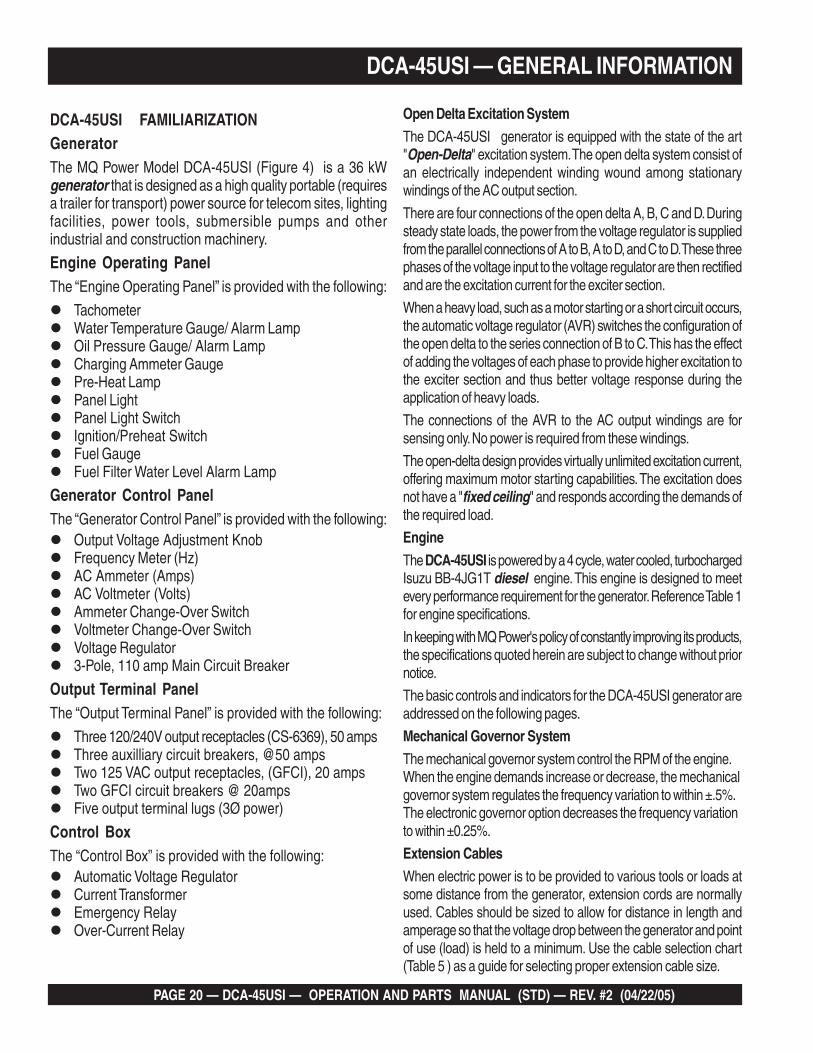
DCA-45USI FAMILIARIZATIONGeneratorThe MQ Power Model DCA-45USI (Figure 4) is a 36 kWgenerator that is designed as a high quality portable (requiresa trailer for transport) power source for telecom sites, lightingfacilities, power tools, submersible pumps and otherindustrial and construction machinery.
Engine Operating PanelThe “Engine Operating Panel” is provided with the following:
TachometerWater Temperature Gauge/ Alarm LampOil Pressure Gauge/ Alarm LampCharging Ammeter GaugePre-Heat LampPanel LightPanel Light SwitchIgnition/Preheat SwitchFuel GaugeFuel Filter Water Level Alarm Lamp
Generator Control PanelThe “Generator Control Panel” is provided with the following:
Output Voltage Adjustment KnobFrequency Meter (Hz)AC Ammeter (Amps)AC Voltmeter (Volts)Ammeter Change-Over SwitchVoltmeter Change-Over SwitchVoltage Regulator3-Pole, 110 amp Main Circuit Breaker
Output Terminal PanelThe “Output Terminal Panel” is provided with the following:
Three 120/240V output receptacles (CS-6369), 50 ampsThree auxilliary circuit breakers, @50 ampsTwo 125 VAC output receptacles, (GFCI), 20 ampsTwo GFCI circuit breakers @ 20ampsFive output terminal lugs (3Ø power)
Control BoxThe “Control Box” is provided with the following:
Automatic Voltage RegulatorCurrent TransformerEmergency RelayOver-Current Relay
Open Delta Excitation System
The DCA-45USI generator is equipped with the state of the art"Open-Delta" excitation system. The open delta system consist ofan electrically independent winding wound among stationarywindings of the AC output section.
There are four connections of the open delta A, B, C and D. Duringsteady state loads, the power from the voltage regulator is suppliedfrom the parallel connections of A to B, A to D, and C to D. These threephases of the voltage input to the voltage regulator are then rectifiedand are the excitation current for the exciter section.
When a heavy load, such as a motor starting or a short circuit occurs,the automatic voltage regulator (AVR) switches the configuration ofthe open delta to the series connection of B to C. This has the effectof adding the voltages of each phase to provide higher excitation tothe exciter section and thus better voltage response during theapplication of heavy loads.
The connections of the AVR to the AC output windings are forsensing only. No power is required from these windings.
The open-delta design provides virtually unlimited excitation current,offering maximum motor starting capabilities. The excitation doesnot have a "fixed ceiling" and responds according the demands ofthe required load.
Engine
The DCA-45USI is powered by a 4 cycle, water cooled, turbochargedIsuzu BB-4JG1T diesel engine. This engine is designed to meetevery performance requirement for the generator. Reference Table 1for engine specifications.
In keeping with MQ Power's policy of constantly improving its products,the specifications quoted herein are subject to change without priornotice.
The basic controls and indicators for the DCA-45USI generator areaddressed on the following pages.
Mechanical Governor System
The mechanical governor system control the RPM of the engine.When the engine demands increase or decrease, the mechanicalgovernor system regulates the frequency variation to within ±.5%.The electronic governor option decreases the frequency variationto within ±0.25%.
Extension Cables
When electric power is to be provided to various tools or loads atsome distance from the generator, extension cords are normallyused. Cables should be sized to allow for distance in length andamperage so that the voltage drop between the generator and pointof use (load) is held to a minimum. Use the cable selection chart(Table 5 ) as a guide for selecting proper extension cable size.

DCA-45USI — OPERATION AND PARTS MANUAL (STD) — REV. #2 (04/22/05) — PAGE 21
DCA-45USI — MAJOR COMPONENTS
Figure 4. Major Components
3elbaT . stnenopmoCrojaMrotareneG
.ONMETI NOITPIRCSED
1 ylbmessArelffuM
2 ylbmessAenignE
3 ylbmessArenaelCriA
4 ylbmessArotareneG
5 ylbmessAlanimreTtuptuO
6 ylbmessAknaTleuF
7 ylbmessAyrettaB
8 ylbmessAlenaPlortnoCrotareneG
9 ylbmessAlenaPgnitarepOenignE
PAGE 22 — DCA-45USI — OPERATION AND PARTS MANUAL (STD) — REV. #2 (04/22/05)
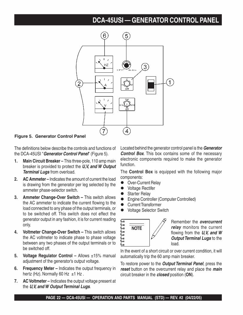
DCA-45USI — GENERATOR CONTROL PANEL
The definitions below describe the controls and functions ofthe DCA-45USI "Generator Control Panel" (Figure 5).
1. Main Circuit Breaker – This three-pole, 110 amp mainbreaker is provided to protect the U,V, and W OutputTerminal Lugs from overload.
2. AC Ammeter – Indicates the amount of current the loadis drawing from the generator per leg selected by theammeter phase-selector switch.
3. Ammeter Change-Over Switch – This switch allowsthe AC ammeter to indicate the current flowing to theload connected to any phase of the output terminals, orto be switched off. This switch does not effect thegenerator output in any fashion, it is for current readingonly.
4. Voltmeter Change-Over Switch – This switch allowsthe AC voltmeter to indicate phase to phase voltagebetween any two phases of the output terminals or tobe switched off.
5. Voltage Regulator Control – Allows ±15% manualadjustment of the generator’s output voltage.
6. Frequency Meter – Indicates the output frequency inhertz (Hz). Normally 60 Hz ±1 Hz .
7. AC Voltmeter – Indicates the output voltage present atthe U,V, and W Output Terminal Lugs.
Located behind the generator control panel is the GeneratorControl Box. This box contains some of the necessaryelectronic components required to make the generatorfunction.
The Control Box is equipped with the following majorcomponents:
Over-Current RelayVoltage RectiferStarter RelayEngine Controller (Computer Controlled)Current TransformerVoltage Selector Switch
Remember the overcurrentrelay monitors the currentflowing from the U,V, and WOutput Terminal Lugs to theload.
In the event of a short circuit or over current condition, it willautomatically trip the 60 amp main breaker.
To restore power to the Output Terminal Panel, press thereset button on the overcurrent relay and place the maincircuit breaker in the closed position (ON).
Figure 5. Generator Control Panel
NOTE

DCA-45USI — OPERATION AND PARTS MANUAL (STD) — REV. #2 (04/22/05) — PAGE 23
DCA-45USI — ENGINE OPERATING PANEL
The definitions below describe the controls and functions ofthe DCA-45USI "Engine Operating Panel" (Figure 6).
1. Panel Light - Normally used in dark places or at night.When activated, panel will luminate. When the generatoris not in use, turn the panel light switch to the OFFposition.
2. Panel Light Switch- When activated, will turn on controlpanel light.
3. Oil Pressure Lamp - Indicates that the oil pressure istoo low and will shut down the engine.
4. Water Temperature Lamp - Indicates that the watertemperature is too hot and will shut down the engine.
5. Fuel Filter Water Level Alarm Lamp - This lamp turnson when water in the filter is detected. Drain the waterin the fuel filter strainer to correct the problem.
6. Pre-heat Lamp - This indicates when the engine hasbeen preheated and is ready for starting. In cold weatherconditions, it may be several minutes before the lampilluminates.
7. Fuel Leak Detected Alarm – This indicates that liquidis present in the fuel tank containment basin. Drain thecontainment basin and repair any leaks.
8. Tachometer – Indicates engine speed in RPM’s for60 Hz operation. This meter should indicate 1800 RPM’swhen the rated load is applied. In addition a built in hourmeter will record the number of operational hours thatthe generator has been in use.
9. Fuel Gauge - Indicates amount of diesel fuel available.
10. Charging Ammeter Gauge – Indicates the currentbeing supplied by the engine’s alternator which providescurrent for generator’s control circuits and batterycharging system.
11. Water Temperature Gauge – During normal operationthis gauge be should read between 165o F to 203o F.
12. Oil Pressure Gauge – Normal operation should be about28 to 71 psi. When starting the generator the oil pressuremay read a bit higher, but after the engine warms upthe oil pressure should return to normal.
13. Starter Switch – Three position switch, stop,preheat/run and start. Insert ignition key to start andstop engine.
Figure 6. Engine Operating Panel
PAGE 24 — DCA-45USI — OPERATION AND PARTS MANUAL (STD) — REV. #2 (04/22/05)
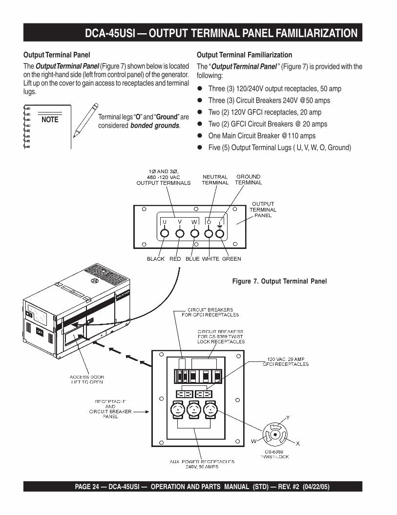
Output Terminal Familiarization
The “Output Terminal Panel ” (Figure 7) is provided with thefollowing:
Three (3) 120/240V output receptacles, 50 amp
Three (3) Circuit Breakers 240V @50 amps
Two (2) 120V GFCI receptacles, 20 amp
Two (2) GFCI Circuit Breakers @ 20 amps
One Main Circuit Breaker @110 amps
Five (5) Output Terminal Lugs ( U, V, W, O, Ground)
Output Terminal PanelThe Output Terminal Panel (Figure 7) shown below is locatedon the right-hand side (left from control panel) of the generator.Lift up on the cover to gain access to receptacles and terminallugs.
Terminal legs “O” and “Ground” areconsidered bonded grounds.
Figure 7. Output Terminal Panel
DCA-45USI — OUTPUT TERMINAL PANEL FAMILIARIZATION
NOTE
DCA-45USI — OPERATION AND PARTS MANUAL (STD) — REV. #2 (04/22/05) — PAGE 25
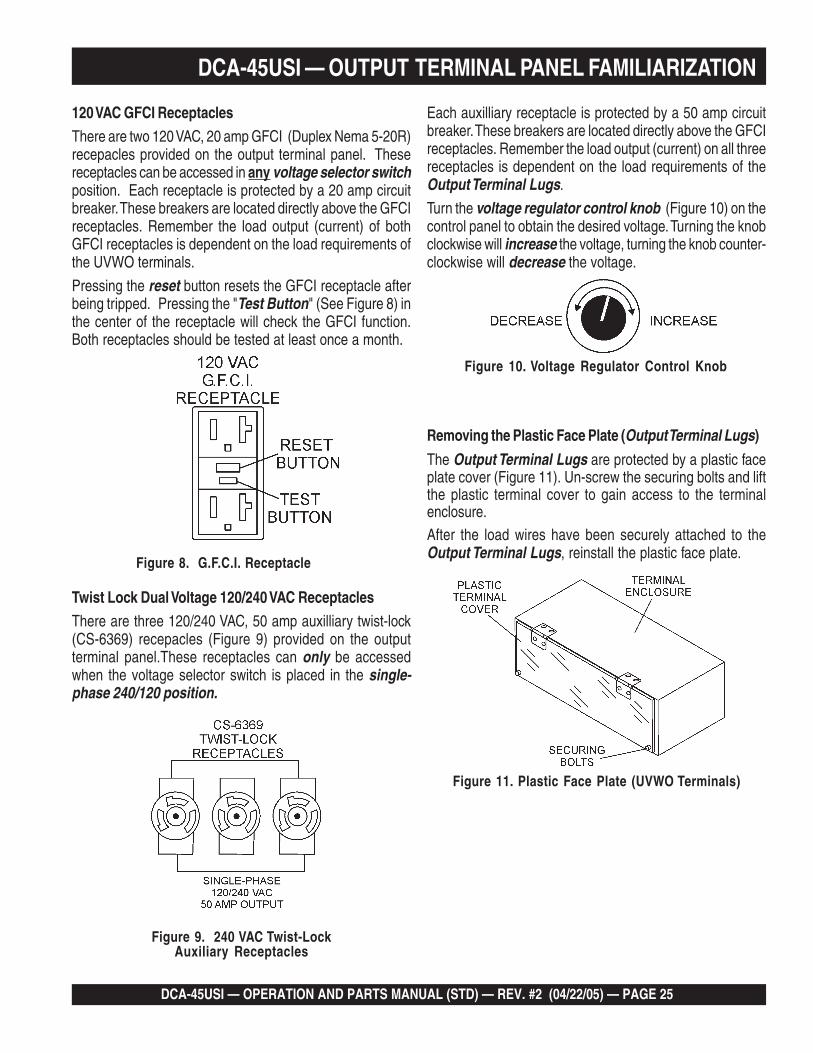
120 VAC GFCI ReceptaclesThere are two 120 VAC, 20 amp GFCI (Duplex Nema 5-20R)recepacles provided on the output terminal panel. Thesereceptacles can be accessed in any voltage selector switchposition. Each receptacle is protected by a 20 amp circuitbreaker. These breakers are located directly above the GFCIreceptacles. Remember the load output (current) of bothGFCI receptacles is dependent on the load requirements ofthe UVWO terminals.
Pressing the reset button resets the GFCI receptacle afterbeing tripped. Pressing the "Test Button" (See Figure 8) inthe center of the receptacle will check the GFCI function.Both receptacles should be tested at least once a month.
Figure 8. G.F.C.I. Receptacle
Each auxilliary receptacle is protected by a 50 amp circuitbreaker. These breakers are located directly above the GFCIreceptacles. Remember the load output (current) on all threereceptacles is dependent on the load requirements of theOutput Terminal Lugs.
Turn the voltage regulator control knob (Figure 10) on thecontrol panel to obtain the desired voltage. Turning the knobclockwise will increase the voltage, turning the knob counter-clockwise will decrease the voltage.
Figure 9. 240 VAC Twist-LockAuxiliary Receptacles
DCA-45USI — OUTPUT TERMINAL PANEL FAMILIARIZATION
Twist Lock Dual Voltage 120/240 VAC ReceptaclesThere are three 120/240 VAC, 50 amp auxilliary twist-lock(CS-6369) recepacles (Figure 9) provided on the outputterminal panel.These receptacles can only be accessedwhen the voltage selector switch is placed in the single-phase 240/120 position.
Figure 10. Voltage Regulator Control Knob
Figure 11. Plastic Face Plate (UVWO Terminals)
Removing the Plastic Face Plate (Output Terminal Lugs)
The Output Terminal Lugs are protected by a plastic faceplate cover (Figure 11). Un-screw the securing bolts and liftthe plastic terminal cover to gain access to the terminalenclosure.After the load wires have been securely attached to theOutput Terminal Lugs, reinstall the plastic face plate.
PAGE 26 — DCA-45USI — OPERATION AND PARTS MANUAL (STD) — REV. #2 (04/22/05)
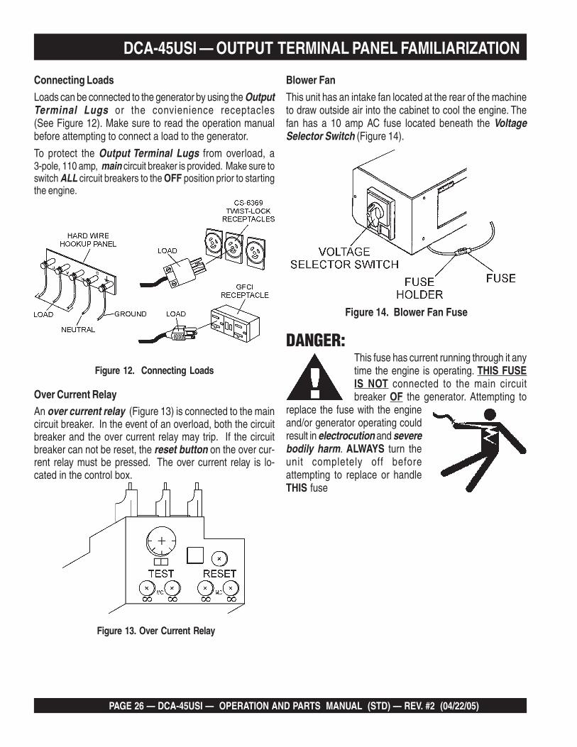
Figure 12. Connecting Loads
Connecting Loads
Loads can be connected to the generator by using the OutputTerminal Lugs or the convienience receptacles(See Figure 12). Make sure to read the operation manualbefore attempting to connect a load to the generator.
To protect the Output Terminal Lugs from overload, a3-pole, 110 amp, main circuit breaker is provided. Make sure toswitch ALL circuit breakers to the OFF position prior to startingthe engine.
DCA-45USI — OUTPUT TERMINAL PANEL FAMILIARIZATION
Over Current RelayAn over current relay (Figure 13) is connected to the maincircuit breaker. In the event of an overload, both the circuitbreaker and the over current relay may trip. If the circuitbreaker can not be reset, the reset button on the over cur-rent relay must be pressed. The over current relay is lo-cated in the control box.
Figure 13. Over Current Relay
Blower Fan
This unit has an intake fan located at the rear of the machineto draw outside air into the cabinet to cool the engine. Thefan has a 10 amp AC fuse located beneath the VoltageSelector Switch (Figure 14).
This fuse has current running through it anytime the engine is operating. THIS FUSEIS NOT connected to the main circuitbreaker OF the generator. Attempting to
replace the fuse with the engineand/or generator operating couldresult in electrocution and severebodily harm. ALWAYS turn theunit completely off beforeattempting to replace or handleTHIS fuse
DANGER:
Figure 14. Blower Fan Fuse
DCA-45USI — OPERATION AND PARTS MANUAL (STD) — REV. #2 (04/22/05) — PAGE 27
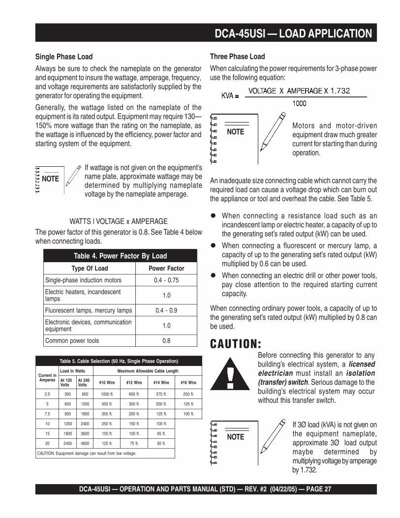
DCA-45USI — LOAD APPLICATION
Single Phase Load
Always be sure to check the nameplate on the generatorand equipment to insure the wattage, amperage, frequency,and voltage requirements are satisfactorily supplied by thegenerator for operating the equipment.
Generally, the wattage listed on the nameplate of theequipment is its rated output. Equipment may require 130—150% more wattage than the rating on the nameplate, asthe wattage is influenced by the efficiency, power factor andstarting system of the equipment.
Motors and motor-drivenequipment draw much greatercurrent for starting than duringoperation.
When connecting ordinary power tools, a capacity of up tothe generating set’s rated output (kW) multiplied by 0.8 canbe used.
If wattage is not given on the equipment'sname plate, approximate wattage may bedetermined by multiplying nameplatevoltage by the nameplate amperage.
The power factor of this generator is 0.8. See Table 4 belowwhen connecting loads.
CAUTION:
If 3Ø load (kVA) is not given onthe equipment nameplate,approximate 3Ø load outputmaybe determined bymultiplying voltage by amperageby 1.732.
When connecting a resistance load such as anincandescent lamp or electric heater, a capacity of up tothe generating set’s rated output (kW) can be used.
When connecting a fluorescent or mercury lamp, acapacity of up to the generating set’s rated output (kW)multiplied by 0.6 can be used.
When connecting an electric drill or other power tools,pay close attention to the required starting currentcapacity.
NOTE
WATTS l VOLTAGE x AMPERAGE
Three Phase Load
When calculating the power requirements for 3-phase poweruse the following equation:
NOTE
An inadequate size connecting cable which cannot carry therequired load can cause a voltage drop which can burn outthe appliance or tool and overheat the cable. See Table 5.
NOTE
daoLyBrotcaFrewoP.4elbaT
daoLfOepyT rotcaFrewoP
srotomnoitcudniesahp-elgniS 57.0-4.0
tnecsednacni,sretaehcirtcelEspmal 0.1
spmalyrucrem,spmaltnecseroulF 9.0-4.0
noitacinummoc,secivedcinortcelEtnempiuqe 0.1
slootrewopnommoC 8.0
)noitarepOesahPelgniS,zH06(noitceleSelbaC.5elbaT
nitnerruCserepmA
sttaWnIdaoL htgneLelbaCelbawollAmumixaM
021tAstloV
042tAstloV eriW01# eriW21# eriW41# eriW61#
5.2 003 006 .tf0001 .tf006 .tf573 .tf052
5 006 0021 .tf005 .tf003 .tf002 .tf521
5.7 009 0081 .tf053 .tf002 .tf521 .tf001
01 0021 0042 .tf052 .tf051 .tf001
51 0081 0063 .tf051 .tf001 .tf56
02 0042 0084 .tf521 .tf57 .tf05
.egatlovwolmorftlusernacegamadtnempiuqE:NOITUAC
Before connecting this generator to anybuilding’s electrical system, a licensedelectrician must install an isolation(transfer) switch. Serious damage to thebuilding’s electrical system may occurwithout this transfer switch.

PAGE 28 — DCA-45USI — OPERATION AND PARTS MANUAL (STD) — REV. #2 (04/22/05)
DCA-45USI — GENERATOR OUTPUTS
GFCI Receptacle Load Capability
The load capability of the GFCI receptacles is directly re-lated to the voltage being supplied at either the output termi-nal lugs or the 3 twist lock auxilliary receptacles.
Tables 8 and 9 show what amount of current is available atthe GFCI receptacles when the UVWO terminals and twistlock receptacles are in use. Be careful that your load doesnot to exceed the available current capability at the recep-tacles.
ytilibapaCdaoLelcatpeceRICFG.8elbaTesUniWK
)9636SC(kcoL-tsiwTtnerruCdaoLelbaliavA
)SPMA(
V021/042Ø1 AMENxelpuDICFGV021R02-5
06 08.85 elcatpecerrepspma56.75 elcatpecerrepspma014.65 elcatpecerrepspma512.55 elcatpecerrepspma02
ytilibapaCdaoLelcatpeceRICFG.8elbaTesUniAVK
)slanimreTOWVU(tnerruCdaoLelbaliavA
)SPMA(
V084/042Ø3 AMENxelpuDICFGV021R02-5
28 08.77 elcatpecerrepspma57.37 elcatpecerrepspma015.96 elcatpecerrepspma514.56 elcatpecerrepspma02
Voltage Selector SwitchThe voltage selector switch (Figure 15) is located abovethe UVWO Hard Wire Hook-up Panel. It has been providedfor ease of voltage selection.
CAUTION:CAUTION:CAUTION:CAUTION:CAUTION:NEVER change the position of the voltageselector switch while the engine is running.ALWAYS place circuit breaker in the openposition before selecting voltage.
Voltage Selector Switch Locking ButtonThe voltage selector switch has a locking button to protectthe generator and load from being switched while the engineis running. To lock the voltage selector switch, press andhold the red button located at the bottom of the switch.
Figure 15. Voltage Selector Switch
Generator AmperageTable 7 describes the generator’s current output capabilityfor both 1Ø-phase and 3Ø phase applications.
elbaliavAsegatloV.6elbaT
esahPeerhT)elbahctiwS(
V802 V022 V042 V614 V044 V084
esahPelgniS)elbahctiwS(
V021 V721 V931 V042 V452 V772
sgnitaRerepmArotareneG.7elbaTJSU54-ACD Wk AVk V021 V802 V042 V084
esahPelgniS 62 A/N 2xA801 A/N A801 A/N
*esahPeerhT 63 54 A/N A521 A801 A45
8.0=rotcaFrewoP*
Generator Output VoltagesA wide range of voltages are available to supply voltage formany different applications. Voltages are selected by usingthe voltage selector switch (Figure 14). To obtain some ofthe voltages as listed in Table 6 (see below) will require afine adjustment using the voltage regulator (VR) controlknob located on the control panel.
DCA-45USI — OPERATION AND PARTS MANUAL (STD) — REV. #2 (04/22/05) — PAGE 29
DCA-45USI — GAUGE READING
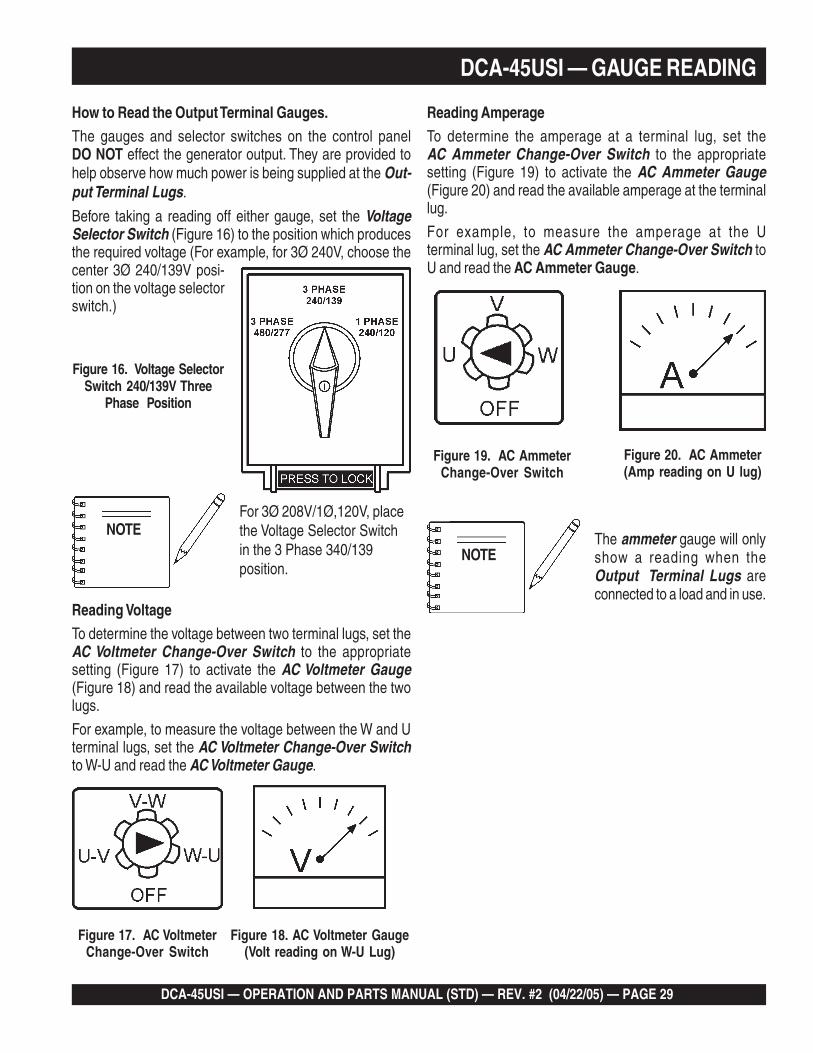
How to Read the Output Terminal Gauges.The gauges and selector switches on the control panelDO NOT effect the generator output. They are provided tohelp observe how much power is being supplied at the Out-put Terminal Lugs.
Before taking a reading off either gauge, set the VoltageSelector Switch (Figure 16) to the position which producesthe required voltage (For example, for 3Ø 240V, choose thecenter 3Ø 240/139V posi-tion on the voltage selectorswitch.)
Figure 16. Voltage SelectorSwitch 240/139V Three
Phase Position
Figure 17. AC VoltmeterChange-Over Switch
Figure 18. AC Voltmeter Gauge(Volt reading on W-U Lug)
For 3Ø 208V/1Ø,120V, placethe Voltage Selector Switchin the 3 Phase 340/139position.
Figure 20. AC Ammeter(Amp reading on U lug)
Figure 19. AC AmmeterChange-Over Switch
The ammeter gauge will onlyshow a reading when theOutput Terminal Lugs areconnected to a load and in use.
NOTE
Reading VoltageTo determine the voltage between two terminal lugs, set theAC Voltmeter Change-Over Switch to the appropriatesetting (Figure 17) to activate the AC Voltmeter Gauge(Figure 18) and read the available voltage between the twolugs.
For example, to measure the voltage between the W and Uterminal lugs, set the AC Voltmeter Change-Over Switchto W-U and read the AC Voltmeter Gauge.
NOTE
Reading AmperageTo determine the amperage at a terminal lug, set theAC Ammeter Change-Over Switch to the appropriatesetting (Figure 19) to activate the AC Ammeter Gauge(Figure 20) and read the available amperage at the terminallug.
For example, to measure the amperage at the Uterminal lug, set the AC Ammeter Change-Over Switch toU and read the AC Ammeter Gauge.
PAGE 30 — DCA-45USI — OPERATION AND PARTS MANUAL (STD) — REV. #2 (04/22/05)
Figure 21. Voltage Selector Switch 240/139VThree-Phase Position
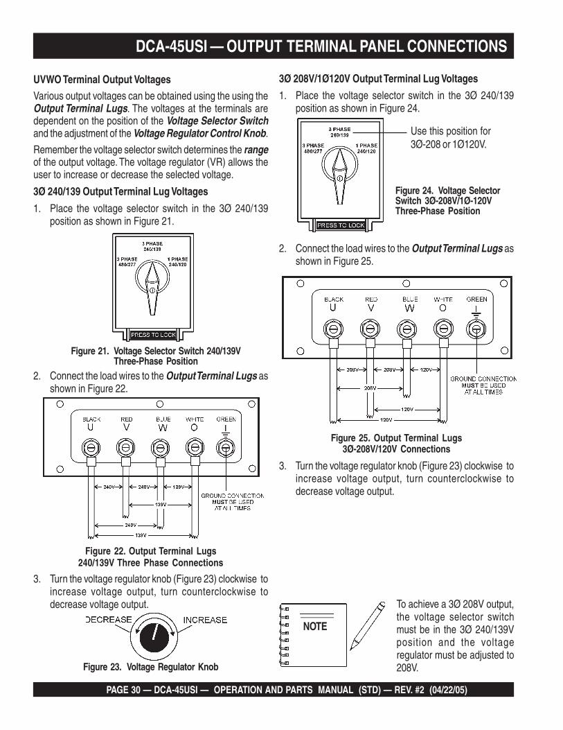
DCA-45USI — OUTPUT TERMINAL PANEL CONNECTIONS
UVWO Terminal Output VoltagesVarious output voltages can be obtained using the using theOutput Terminal Lugs. The voltages at the terminals aredependent on the position of the Voltage Selector Switchand the adjustment of the Voltage Regulator Control Knob.
Remember the voltage selector switch determines the rangeof the output voltage. The voltage regulator (VR) allows theuser to increase or decrease the selected voltage.
3Ø 240/139 Output Terminal Lug Voltages
1. Place the voltage selector switch in the 3Ø 240/139position as shown in Figure 21.
Figure 22. Output Terminal Lugs240/139V Three Phase Connections
2. Connect the load wires to the Output Terminal Lugs asshown in Figure 22.
3. Turn the voltage regulator knob (Figure 23) clockwise toincrease voltage output, turn counterclockwise todecrease voltage output.
3Ø 208V/1Ø120V Output Terminal Lug Voltages
1. Place the voltage selector switch in the 3Ø 240/139position as shown in Figure 24.
Figure 23. Voltage Regulator Knob
Use this position for3Ø-208 or 1Ø120V.
2. Connect the load wires to the Output Terminal Lugs asshown in Figure 25.
3. Turn the voltage regulator knob (Figure 23) clockwise toincrease voltage output, turn counterclockwise todecrease voltage output.
NOTE
To achieve a 3Ø 208V output,the voltage selector switchmust be in the 3Ø 240/139Vposition and the voltageregulator must be adjusted to208V.
Figure 25. Output Terminal Lugs3Ø-208V/120V Connections
Figure 24. Voltage SelectorSwitch 3Ø-208V/1Ø-120VThree-Phase Position

DCA-45USI — OPERATION AND PARTS MANUAL (STD) — REV. #2 (04/22/05) — PAGE 31
Figure 26. Voltage Selector Switch 480/277V Three-Phase Position
3Ø 480/277 Output Terminal Lug Voltages
1. Place the voltage selector switch in the 3Ø 480/277position as shown in Figure 26.
Figure 27. Output Terminal Lugs277/480V Three Phase Connections
2. Connect the load wires to the Output Terminal Lugs asshown in Figure 27.
3. Turn the voltage regulator knob (Figure 23) clockwise toincrease voltage output, turn counterclockwise todecrease voltage output.
1Ø 240V/120V Output Terminal Lug Voltages
1. Place the voltage selector switch in the 1Ø 240/120position as shown in Figure 28.
2. Connect the load wires to the Output Terminal Lugs asshown in Figure 29.
3. Turn the voltage regulator knob (Figure 23) clockwise toincrease voltage output, turn counterclockwise todecrease voltage output.
Figure 29. Output Terminal Lugs1Ø-240V/120V Connections
DCA-45USI — OUTPUT TERMINAL PANEL CONNECTIONS
Figure 28. Voltage Selector Switch 240/120V Single-Phase Position
PAGE 32 — DCA-45USI — OPERATION AND PARTS MANUAL (STD) — REV. #2 (04/22/05)
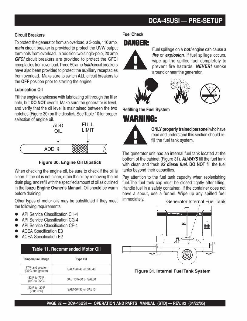
Lubrication Oil
Fill the engine crankcase with lubricating oil through the fillerhole, but DO NOT overfill. Make sure the generator is level.and verify that the oil level is maintained between the twonotches (Figure 30) on the dipstick. See Table 10 for properselection of engine oil.
DCA-45USI — PRE-SETUP
Figure 30. Engine Oil Dipstick
When checking the engine oil, be sure to check if the oil isclean. If the oil is not clean, drain the oil by removing the oildrain plug, and refill with the specified amount of oil as outlinedin the Isuzu Engine Owner's Manual. Oil should be warmbefore draining.
Circuit Breakers
To protect the generator from an overload, a 3-pole, 110 amp,main circuit breaker is provided to protect the UVW outputterminals from overload. In addition two single-pole, 20 ampGFCI circuit breakers are provided to protect the GFCIreceptacles from overload. Three 50 amp load circuit breakershave also been provided to protect the auxiliary receptaclesfrom overload. Make sure to switch ALL circuit breakers tothe OFF position prior to starting the engine.
API Service Classification CH-4API Service Classification CG-4API Service Classification CF-4ACEA Specification E3ACEA Specification E2
Other types of motor oils may be substituted if they meetthe following requirements:
liOrotoMdednemmoceR.11elbaT
egnaRerutarepmeT liOepyT
77 o retaergdnaF52( o )retaergdnaC 04EASro04-W51EAS
23 o 77otF oF0( o 52otC o )C 03EASro03-W01EAS
22- o 23-otF oF03-( o 0C o )C 01EASro03-W01EAS
ONLY properly trained personel who haveread and understand this section should re-fill the fuel tank system.
Figure 31. Internal Fuel Tank System
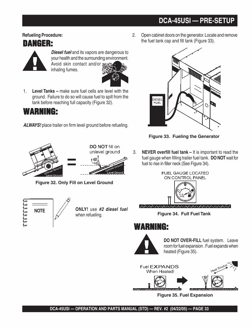
Fuel spillage on a hot! engine can cause afire or explosion. If fuel spillage occurs,wipe up the spilled fuel completely toprevent fire hazards. NEVER! smokearound or near the generator.
DANGER:DANGER:DANGER:DANGER:DANGER:
Refilling the Fuel System
Fuel Check
WARNING:WARNING:WARNING:WARNING:WARNING:
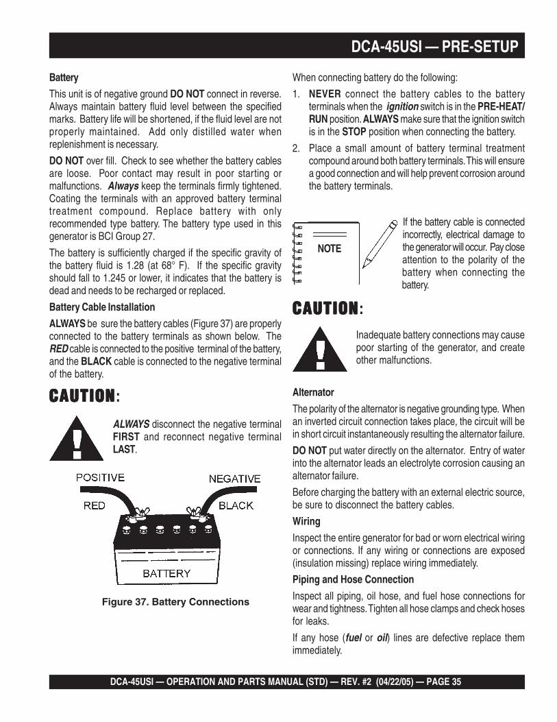
The generator unit has an internal fuel tank located at thebottom of the cabinet (Figure 31). ALWAYS fill the fuel tankwith clean and fresh #2 diesel fuel. DO NOT fill the fueltanks beyond their capacities.
Pay attention to the fuel tank capacity when replenishingfuel.The fuel tank cap must be closed tightly after filling.Handle fuel in a safety container. If the container does nothave a spout, use a funnel. Wipe up any spilled fuelimmediately.
DCA-45USI — OPERATION AND PARTS MANUAL (STD) — REV. #2 (04/22/05) — PAGE 33
DCA-45USI — PRE-SETUP
Refueling Procedure:
1. Level Tanks – make sure fuel cells are level with theground. Failure to do so will cause fuel to spill from thetank before reaching full capacity (Figure 32).
DANGER:DANGER:DANGER:DANGER:DANGER:
WARNING:WARNING:WARNING:WARNING:WARNING:
Figure 32. Only Fill on Level Ground
ONLY! use #2 diesel fuelwhen refueling.
Diesel fuel and its vapors are dangerous toyour health and the surrounding environment.Avoid skin contact and/orinhaling fumes.
ALWAYS! place trailer on firm level ground before refueling.
NOTE
3. NEVER overfill fuel tank – It is important to read thefuel gauge when filling trailer fuel tank. DO NOT wait forfuel to rise in filler neck (See Figure 34).
Figure 34. Full Fuel Tank
Figure 35. Fuel Expansion
WARNING:WARNING:WARNING:WARNING:WARNING:DO NOT OVER-FILL fuel system. Leaveroom for fuel expansion . Fuel expands whenheated (Figure 35).
2. Open cabinet doors on the generator. Locate and removethe fuel tank cap and fill tank (Figure 33).
Figure 33. Fueling the Generator

PAGE 34 — DCA-45USI — OPERATION AND PARTS MANUAL (STD) — REV. #2 (04/22/05)
Coolant (Ethylane Glycol [Green] / Water — 50/50 mix)Use only drinkable tap water. If hard water or water withmany impurities is used, the inside of the engine and radiatormay become coated with deposits and cooling efficiencywill be reduced.
An anticorrosion additive added to the water will help preventdeposits and corrosion in the cooling system. See the enginemanual for further details.
CAUTION:CAUTION:CAUTION:CAUTION:CAUTION:If adding coolant/antifreezemix to the radiator, DONOT remove the radiatorcap until the unit hascompletely cooled. The possibility of hot!
coolant exists which can cause severe burns.
Day-to-day addition of coolant is done from the recoverytank. When adding coolant to the radiator, DO NOT removethe radiator cap until the unit has completely cooled. SeeTable 12 for engine, radiator, and recovery tank coolantcapacities. Make sure the coolant level in the recovery tankis always between the "H" and the "L" markings.
Operation Freezing Weather
When operating in freezing weather, be certain the properamount of antifreeze (Table 13) has been added. CAUTIONCAUTIONCAUTIONCAUTIONCAUTION:
Cleaning the Radiator
The engine may overheat if the radiator fins becomeoverloaded with dust or debris. Periodically clean the radiatorfins with compressed air. Cleaning inside the machine isdangerous, so clean only with the engine turned off and thenegative battery terminal disconnected.
Air Cleaner
Periodic cleaning/replacement is necessary. Inspect it inaccordance with the Isusu Engine Owner's Manual.
Fan Belt Tension
A slack fan belt may contribute to overheating, or toinsufficient charging of the battery. Inspect the fan belt fordamage and wear and adjust it in accordance with the IsuzuEngine Owner's Manual.
The fan belt tension is proper if the fan belt bends 10 to 15mm (Figure 38) when depressed with the thumb as shownbelow.
Figure 36. Fan Belt Tension
DCA-45USI — PRE-SETUP
When the antifreeze is mixed withwater, the antifreeze mixing ratiomust be less than 50%.
NOTE
NEVER! place handsnear the belts or fan whilethe generator set isrunning.
yticapaCtnalooC.21elbaT
rotaidaRdnaenignE )L02(.laG3.5
knaTevreseR )L1(.laG62.0
serutarepmeTgnitarepOezeerF-itnA.31elbaT
%loVezeerF-itnA
tnioPgnizeerF tnioPgnilioB
C° F° C° F°
04 42- 21- 601 222
05 73- 43- 801 622
DCA-45USI — OPERATION AND PARTS MANUAL (STD) — REV. #2 (04/22/05) — PAGE 35
DCA-45USI — PRE-SETUP
When connecting battery do the following:
1. NEVER connect the battery cables to the batteryterminals when the ignition switch is in the PRE-HEAT/RUN position. ALWAYS make sure that the ignition switchis in the STOP position when connecting the battery.
2. Place a small amount of battery terminal treatmentcompound around both battery terminals. This will ensurea good connection and will help prevent corrosion aroundthe battery terminals.
Figure 37. Battery Connections
CAUTIONCAUTIONCAUTIONCAUTIONCAUTION:
ALWAYS disconnect the negative terminalFIRST and reconnect negative terminalLAST.
CAUTIONCAUTIONCAUTIONCAUTIONCAUTION:Inadequate battery connections may causepoor starting of the generator, and createother malfunctions.
Alternator
The polarity of the alternator is negative grounding type. Whenan inverted circuit connection takes place, the circuit will bein short circuit instantaneously resulting the alternator failure.
DO NOT put water directly on the alternator. Entry of waterinto the alternator leads an electrolyte corrosion causing analternator failure.
Before charging the battery with an external electric source,be sure to disconnect the battery cables.
Wiring
Inspect the entire generator for bad or worn electrical wiringor connections. If any wiring or connections are exposed(insulation missing) replace wiring immediately.
Piping and Hose Connection
Inspect all piping, oil hose, and fuel hose connections forwear and tightness. Tighten all hose clamps and check hosesfor leaks.
If any hose (fuel or oil) lines are defective replace themimmediately.
If the battery cable is connectedincorrectly, electrical damage tothe generator will occur. Pay closeattention to the polarity of thebattery when connecting thebattery.
NOTE
Battery
This unit is of negative ground DO NOT connect in reverse.Always maintain battery fluid level between the specifiedmarks. Battery life will be shortened, if the fluid level are notproperly maintained. Add only distilled water whenreplenishment is necessary.
DO NOT over fill. Check to see whether the battery cablesare loose. Poor contact may result in poor starting ormalfunctions. Always keep the terminals firmly tightened.Coating the terminals with an approved battery terminaltreatment compound. Replace battery with onlyrecommended type battery. The battery type used in thisgenerator is BCI Group 27.
The battery is sufficiently charged if the specific gravity ofthe battery fluid is 1.28 (at 68° F). If the specific gravityshould fall to 1.245 or lower, it indicates that the battery isdead and needs to be recharged or replaced.
Battery Cable Installation
ALWAYS be sure the battery cables (Figure 37) are properlyconnected to the battery terminals as shown below. TheRED cable is connected to the positive terminal of the battery,and the BLACK cable is connected to the negative terminalof the battery.
PAGE 36 — DCA-45USI — OPERATION AND PARTS MANUAL (STD) — REV. #2 (04/22/05)
5. Preheat the engine glow plugs by turning the ignitionkey (Figure 42) to the PRE-HEAT/RUN position. Whenthe preheat lamp (Figure 43) turns off, proceedto step 6.
Figure 43. Pre-Heat Indicator Lamp
WARNING:WARNING:WARNING:WARNING:WARNING:The engine's exhaust contains harmful
emissions. ALWAYS have adequateventilation when operating. Direct exhaustaway from nearby personnel.
DCA-45USI — GENERATOR START-UP PROCEDURE
Figure 39. Load Connections
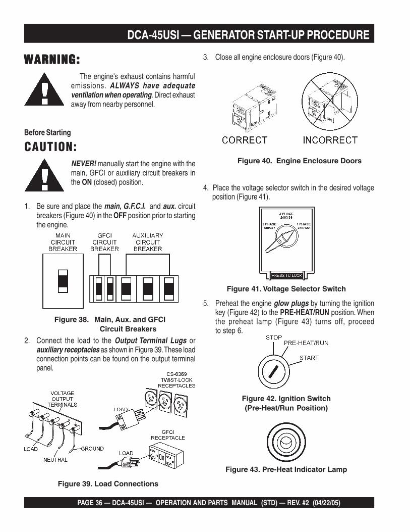
NEVER! manually start the engine with themain, GFCI or auxiliary circuit breakers inthe ON (closed) position.
CAUTION:
1. Be sure and place the main, G.F.C.I. and aux. circuitbreakers (Figure 40) in the OFF position prior to startingthe engine.
Before Starting
Figure 38. Main, Aux. and GFCI Circuit Breakers
2. Connect the load to the Output Terminal Lugs orauxiliary receptacles as shown in Figure 39. These loadconnection points can be found on the output terminalpanel.
3. Close all engine enclosure doors (Figure 40).
Figure 40. Engine Enclosure Doors
4. Place the voltage selector switch in the desired voltageposition (Figure 41).
Figure 41. Voltage Selector Switch
Figure 42. Ignition Switch(Pre-Heat/Run Position)
DCA-45USI — OPERATION AND PARTS MANUAL (STD) — REV. #2 (04/22/05) — PAGE 37
Figure 47. Voltage Adjust Control Knob
Figure 48. Ammeter (No Load)
11. The ammeter (Figure 48) will indicate zero amps with noload applied. When a load is applied, this meter willindicate the amount of current that the load is drawingfrom the generator.
DCA-45USI — GENERATOR START-UP PROCEDURE
8. The generator's frequency meter (Figure 45) displaysthe 60 cycle output frequency in HERTZ.
9. The generator's voltage meter (Figure 46) displays theoutput voltage in VOLTS.
Figure 46. AC Voltmeter
Figure 45. Frequency Meter (Hz)
10. If the voltage is not reading at the specified level, usethe voltage adjustment control knob (Figure 47) toincrease or decrease the voltage until you reach thedesired voltage.
7. Let the engine run for 3-5 minutes and listen and checkfor any abnormal sounds or smells. Check for fuel leaks,and noises that would associate with a loose cover orhardware.
Check the electric motor fan cooling the radiator forabnormal speed, sound or vibration conditions.
If any of the above mentioned conditions exists, shut-down the engine and correct the problem before operatingthe generator.
6. Turn the ignition key to the START position (Figure 44).Once the engine starts, release the ignition key andallow it to return to the PRE-HEAT/RUN position(Figure 42).
If the engine fails to start after 10 seconds, waitapproximately 30 seconds and repeat steps 5-6.
Figure 44. Ignition Switch(Start Position)
PAGE 38 — DCA-45USI — OPERATION AND PARTS MANUAL (STD) — REV. #2 (04/22/05)
DCA-45USI — GENERATOR START-UP PROCEDURE
Figure 51. Engine Tachometer
14. The tachometer (Figure 51) will indicate the speed ofthe engine when the generator is operating. Under normaloperating conditions this speed is approximately 1800RPM’s.
15. Turn the main, GFCI, and aux. circuit breakers to theON position (Figure 52).
13. The coolant temperature gauge (Figure 50) will indicatethe coolant temperature. Under normal operatingconditions the coolant temperature is between 165 and203° degrees Fahrenheit.
Figure 50. Coolant Temperature Gauge
16. Observe the generator's ammeter (Figure 53) and verifyit reads the anticipated amount of current with respectto the load. The ammeter will only display a currentreading if the load is in use.
Figure 53. Ammeter (Load)
Figure 52. Main, AUX. and GFCI Circuit Breakers (ON)
12. The engine oil pressure gauge (Figure 49) will indicatethe oil pressure of the engine. Under normal operatingconditions the oil pressure is approximately
Figure 49. Oil Pressure Gauge
17. The generator will run until manually stopped or anabnormal condition occurs.
DCA-45USI — OPERATION AND PARTS MANUAL (STD) — REV. #2 (04/22/05) — PAGE 39
Normal Shut-down Procedure
To shutdown the generator, use the following procedure:
1. Switch the MAIN, AUX and GFCI circuit breakers(Figure 54) to the OFF position (no load).
Figure 54. Main, AUX. and GFCI Circuit Breakers (OFF)
Emergency Shut-down Procedure
1. To shut-down the engine in the event of an emergency,switch the MAIN, GFCI and LOAD (Figure 54) circuitbreakers to OFF position.
2. Turn the ignition switch key to the STOP position(Figure 55).
3. Let the engine cool by running it for 3-5 minutes with noload applied (circuit breakers in the OFF position).
4. Place the ignition switch (Figure 55) in the STOP position,remove the key and store in a safe place.
Figure 55. Ignition Switch (Off Position)
5. Remove all loads from the generator.
6. Allow for sufficient time for cooling and then inspectthe complete unit for any damage or loosening thatmay have occured during operation.
7. Check the engine oil, coolant and fuel levels. Replenishas necessary.
DCA-45USI — GENERATOR SHUT-DOWN PROCEDURE
Automatic Shut-down SystemWN
This unit is equipped with safety devices to automaticallystop the engine in the event of low oil pressure(approx. 14 PSI.), or high water temperature(approx. 221° F). The alarm lamps on the Engine ControlPanel (Figure 5) illuminate to signify the reason for theshut-down.
Engine protection is furnishedduring operation, but cannotreplace normal preventivemaintenance.
Regularly maintain the unit as specified in the Maintenancesection of this manual to prevent damage.
NOTE
CAUTION:After automatic shut-down, ALWAYS inspectthe unit and eliminate any problems beforeattempting to restart. Failure to do so candamage the unit.
Before inspecting, turn the starter switch to the STOPposition, place all Generator Circuit Breakers in the OFFposition and allow sufficient time for adequate cooling. Whenready to restart, complete all steps in the Generator StartupProcedure section of this manual.
PAGE 40 — DCA-45USI — OPERATION AND PARTS MANUAL (STD) — REV. #2 (04/22/05)
DCA-45USI — MAINTENANCE
ECNANETNIAM/NOITCEPSNI.41ELBAT srH01YLIAD srH052 srH005 srH0001
ENIGNE
sleveLdiulFenignEkcehC X
renaelCriAkcehC X
leveLdicAyrettaBkcehC X
noitidnoCtleBnaFkcehC X
skaeLrofkcehC X
tnemniatnoCrofsleveLdiulFkcehC X
straPfogninesooLrofkcehC X
*retliFdnaliOenignEecalpeR 1 X
knaTleuFfomottoBniarD X
lwoBrotarepeSretaW/retliFleuFkcehC X
edistuOdnaedisnI,tinUnaelC X
*esoHybwolBkcehC 2 X
retliFriAnaelC X
*tnemelEretliFriAecalpeR 3 X
retliFleuFegnahC * 4 X
leveLnoitcetorPtnalooCkcehCdnarotaidaRnaelC X
spmalCdnasesoHllakcehC X
knaTleuFfoedisnInaelC X
ROTARENEGecnatsiseRnoitalusnIerusaeM X
gniraeBtroppuSraeRrotoRkcehC X
.ylnoemittsrif,sruoh05taretliffnalioenigneecalpeR1*
htiw,toofrephcni2/1atsaeltasiesohybwolbehtfoepolsehttahterusne,decalperebotsdeenesohybwolbfI2*.lioro/dnaerutsiomtcellocdluoctahtspidrosgason
H).ni52(.mm526fommuccavaswohsrotacidninoitcirtsernehwtnemeleretlifriayramirpecalpeR3* 20
.sgulpynanesoolotyrassecentonsitI.gnideelbrianehwretlifleufnopmupgnimirphsuP4*
Service Daily
If the engine is operating in very dusty or dry grassconditions, a clogged air cleaner will result. This can lead toa loss of power, excessive carbon buildup in the combustionchamber and high fuel consumption. Change air cleanermore frequently if these conditions exists.
Fuel Addition
Add diesel fuel (the grade may vary according to seasonand locations). Always pour through the mesh filter.
Removing Water from the Fuel Tank
After prolonged use, water and other impurities accumulatein the bottom of the tank. Occasionally inspect the fuel tankfor water contamination and drain the contents if required.
During cold weather, the more empty volume inside the tank,the easier it is for water to condense. This can be reducedby keeping the tank full with diesel fuel.
General Inspection
Prior to each use, the generator should be cleaned andinspected for deficiencies. Check for loose, missing ordamaged nuts, bolts or other fasteners. Also check for fuel,oil, and coolant leaks.
Engine Side (Refer to the Engine Instruction Manual)
Air Cleaner
Every 250 hours: Remove air cleaner element and clean theheavy duty paper element with light spray of compressedair. Replace the air cleaner as needed.
Air Cleaner with Dust Indicator
This indicator is attached to the air cleaner. When the aircleaner element is clogged, air intake restriction becomesgreater and the dust indicator signal shows RED meaningthe element needs changing. After changing the air element,press the dust indicator button to reset the indicator.

DCA-45USI — OPERATION AND PARTS MANUAL (STD) — REV. #2 (04/22/05) — PAGE 41
DCA-45USI — MAINTENANCE
Flushing Out Radiator and Replacing Coolant
Open both cocks located at the crankcase side and atthe lower part of the radiator and drain coolant. Open theradiator cap while draining. Remove the overflow tankand drain.
Check hoses for softening and kinks. Check clamps forsigns of leakage.
Flush the radiator by running clean tap water throughradiator until signs of rust and dirt are removed. DO NOTclean radiator core with any objects, such as ascrewdriver.
Tighten both cocks and replace the overflow tank.
Replace with coolant (Table 12 for correct mixture).
Close radiator cap tightly.
Generator Storage
For longe term storage of the generator the following isrecommended:
Fill the fuel tank completely. Treat with a fuel stabilizer ifnecessary.
Completely drain the oil from the crankcase and refill ifnecessary with fresh oil.
Clean the entire generator, internal and external.
Cover the generating set and store in a clean, dry place.
Disconnect the battery.
Make sure engine coolant is at proper level.
If generator is mounted on a trailer, jack trailer up andplace on blocks so tires do not touch the ground or blockand completely remove the tires.
CAUTION:CAUTION:CAUTION:CAUTION:CAUTION:Allow engine to cool when flushing outradiator. Flushing the radiator while hot couldcause serious burnsfrom water or steam.
Air Removal
If air enters the fuel injection system of a diesel engine,starting becomes impossible. After running out of fuel, orafter disassembling the fuel system, bleed the systemaccording to the following procedure.
To restart after running out of fuel, turn the switch to the ONposition for 15-30 seconds. Try again, if needed. This unit isequipped with an automatic air bleeding system.
Check Oil Level
Check the crankcase oil level prior to each use, or when thefuel tank is filled. Insufficient oil may cause severe damageto the engine. Make sure the generator is level. The oil levelmust be between the two notches on the dipstick as shownin Figure 33.
Replacing Oil Filter
Remove the old oil filter.
Apply a film of oil to the gasket on the new oil filter.
Install the new oil filter.
After the oil cartridge has been replaced, the engine oilwill drop slightly. Run the engine for a while and checkfor leaks before adding more oil if needed. Cleanexcessive oil from engine.
Replacing Fuel Filter
Replace the fuel filter cartridge with new one every 500hours or so.
Loosen the drain plug at the lower top of the fuel filter.Drain the fuel in the fuel body together with the mixedwater. DO NOT spill the fuel during disassembly.
Vent any air.
PAGE 42 — DCA-45USI — OPERATION AND PARTS MANUAL (STD) — REV. #2 (04/22/05)
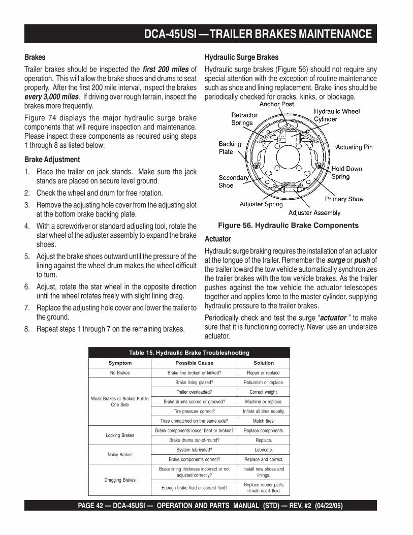
DCA-45USI — TRAILER BRAKES MAINTENANCE
Hydraulic Surge BrakesHydraulic surge brakes (Figure 56) should not require anyspecial attention with the exception of routine maintenancesuch as shoe and lining replacement. Brake lines should beperiodically checked for cracks, kinks, or blockage.
Figure 56. Hydraulic Brake Components
Brake Adjustment
1. Place the trailer on jack stands. Make sure the jackstands are placed on secure level ground.
2. Check the wheel and drum for free rotation.
3. Remove the adjusting hole cover from the adjusting slotat the bottom brake backing plate.
4. With a screwdriver or standard adjusting tool, rotate thestar wheel of the adjuster assembly to expand the brakeshoes.
5. Adjust the brake shoes outward until the pressure of thelining against the wheel drum makes the wheel difficultto turn.
6. Adjust, rotate the star wheel in the opposite directionuntil the wheel rotates freely with slight lining drag.
7. Replace the adjusting hole cover and lower the trailer tothe ground.
8. Repeat steps 1 through 7 on the remaining brakes.
BrakesTrailer brakes should be inspected the first 200 miles ofoperation. This will allow the brake shoes and drums to seatproperly. After the first 200 mile interval, inspect the brakesevery 3,000 miles. If driving over rough terrain, inspect thebrakes more frequently.
Figure 74 displays the major hydraulic surge brakecomponents that will require inspection and maintenance.Please inspect these components as required using steps1 through 8 as listed below:
Actuator
Hydraulic surge braking requires the installation of an actuatorat the tongue of the trailer. Remember the surge or push ofthe trailer toward the tow vehicle automatically synchronizesthe trailer brakes with the tow vehicle brakes. As the trailerpushes against the tow vehicle the actuator telescopestogether and applies force to the master cylinder, supplyinghydraulic pressure to the trailer brakes.
Periodically check and test the surge “actuator ” to makesure that it is functioning correctly. Never use an undersizeactuator.
gnitoohselbuorTekarBciluardyH.51elbaTmotpmyS esuaCelbissoP noituloS
sekarBoN ?deknikronekorbenilekarB .ecalperroriapeR
otlluPsekarBrosekarBkaeWediSenO
?dezalggninilekarB .ecalperrohsinrubeR
?dedaolrevoreliarT .thgiewtcerroC
?devoorgroderocssmurdekarB .ecalperroenihcaM
?tcerrocerusserperiT .yllauqeseritllaetalfnI
?elxaemasehtnodehctamnuseriT .serithctaM
sekarBgnikcoL?nekorbrotneb,esoolstnenopmocekarB .stnenopmocecalpeR
?dnuor-fo-tuosmurdekarB .ecalpeR
sekarBysioN?detacirbulmetsyS .etacirbuL
?tcerrocstnenopmocekarB .tcerrocdnaecalpeR
sekarBgniggarD
tonrotcerrocnissenkcihtgninilekarB?yltcerrocdetsujda
dnaseohswenllatsnI.sgninil
?diulftcerrocrodiulfekarbhguonEstraprebburecalpeR
.diulf4todhtiwllif
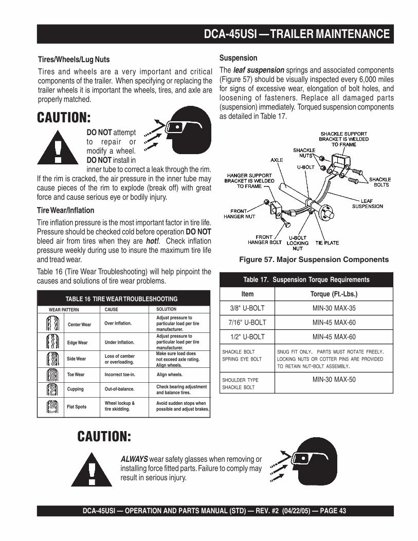
DCA-45USI — OPERATION AND PARTS MANUAL (STD) — REV. #2 (04/22/05) — PAGE 43
DCA-45USI — TRAILER MAINTENANCE
Tires/Wheels/Lug NutsTires and wheels are a very important and criticalcomponents of the trailer. When specifying or replacing thetrailer wheels it is important the wheels, tires, and axle areproperly matched.
CAUTION:DO NOT attemptto repair ormodify a wheel.DO NOT install ininner tube to correct a leak through the rim.
If the rim is cracked, the air pressure in the inner tube maycause pieces of the rim to explode (break off) with greatforce and cause serious eye or bodily injury.
Tire Wear/Inflation
Tire inflation pressure is the most important factor in tire life.Pressure should be checked cold before operation DO NOTbleed air from tires when they are hot!. Check inflationpressure weekly during use to insure the maximum tire lifeand tread wear.
Table 16 (Tire Wear Troubleshooting) will help pinpoint thecauses and solutions of tire wear problems.
CAUTION:ALWAYS wear safety glasses when removing orinstalling force fitted parts. Failure to comply mayresult in serious injury.
SuspensionThe leaf suspension springs and associated components(Figure 57) should be visually inspected every 6,000 milesfor signs of excessive wear, elongation of bolt holes, andloosening of fasteners. Replace all damaged parts(suspension) immediately. Torqued suspension componentsas detailed in Table 17.
Figure 57. Major Suspension Components
WEAR PATTERN CAUSE SOLUTION
Center Wear Over Inflation.Adjust pressure toparticular load per tiremanufacturer.
Edge Wear Under Inflation.Adjust pressure toparticular load per tiremanufacturer.
Side Wear Loss of camberor overloading.
Make sure load doesnot exceed axle rating.Align wheels.
Toe Wear Incorrect toe-in. Align wheels.
Cupping Out-of-balance. Check bearing adjustmentand balance tires.
Flat SpotsWheel lockup &tire skidding.
Avoid sudden stops whenpossible and adjust brakes.
TABLE 16 TIRE WEAR TROUBLESHOOTING
stnemeriuqeReuqroTnoisnepsuS.71elbaT
metI ).sbL-.tF(euqroT
TLOB-U"8/3 53-XAM03-NIM
TLOB-U"61/7 06-XAM54-NIM
TLOB-U"2/1 06-XAM54-NIM
SHACKLE BOLTSPRING EYE BOLT
SNUG FIT ONLY. PARTS MUST ROTATE FREELY.LOCKING NUTS OR COTTER PINS ARE PROVIDEDTO RETAIN NUT-BOLT ASSEMBLY.
SHOULDER TYPESHACKLE BOLT
05-XAM03-NIM
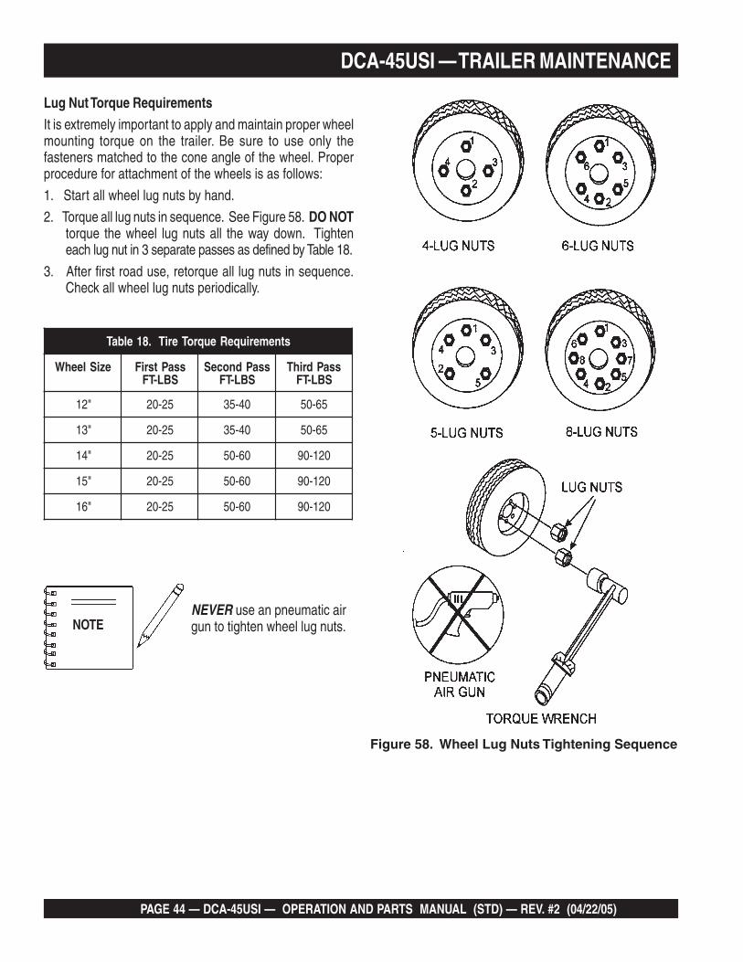
PAGE 44 — DCA-45USI — OPERATION AND PARTS MANUAL (STD) — REV. #2 (04/22/05)
Lug Nut Torque RequirementsIt is extremely important to apply and maintain proper wheelmounting torque on the trailer. Be sure to use only thefasteners matched to the cone angle of the wheel. Properprocedure for attachment of the wheels is as follows:
1. Start all wheel lug nuts by hand.
2. Torque all lug nuts in sequence. See Figure 58. DO NOTtorque the wheel lug nuts all the way down. Tighteneach lug nut in 3 separate passes as defined by Table 18.
3. After first road use, retorque all lug nuts in sequence.Check all wheel lug nuts periodically.
NEVER use an pneumatic airgun to tighten wheel lug nuts.
Figure 58. Wheel Lug Nuts Tightening Sequence
DCA-45USI — TRAILER MAINTENANCE
stnemeriuqeReuqroTeriT.81elbaT
eziSleehW ssaPtsriFSBL-TF
ssaPdnoceSSBL-TF
ssaPdrihTSBL-TF
"21 52-02 04-53 56-05
"31 52-02 04-53 56-05
"41 52-02 06-05 021-09
"51 52-02 06-05 021-09
"61 52-02 06-05 021-09
NOTE

DCA-45USI — OPERATION AND PARTS MANUAL (STD) — REV. #2 (04/22/05) — PAGE 45
DCA-45USI — TRAILER WIRING DIAGRAM
Figure 59. Trailer/Towing Vehicle Wiring Diagram
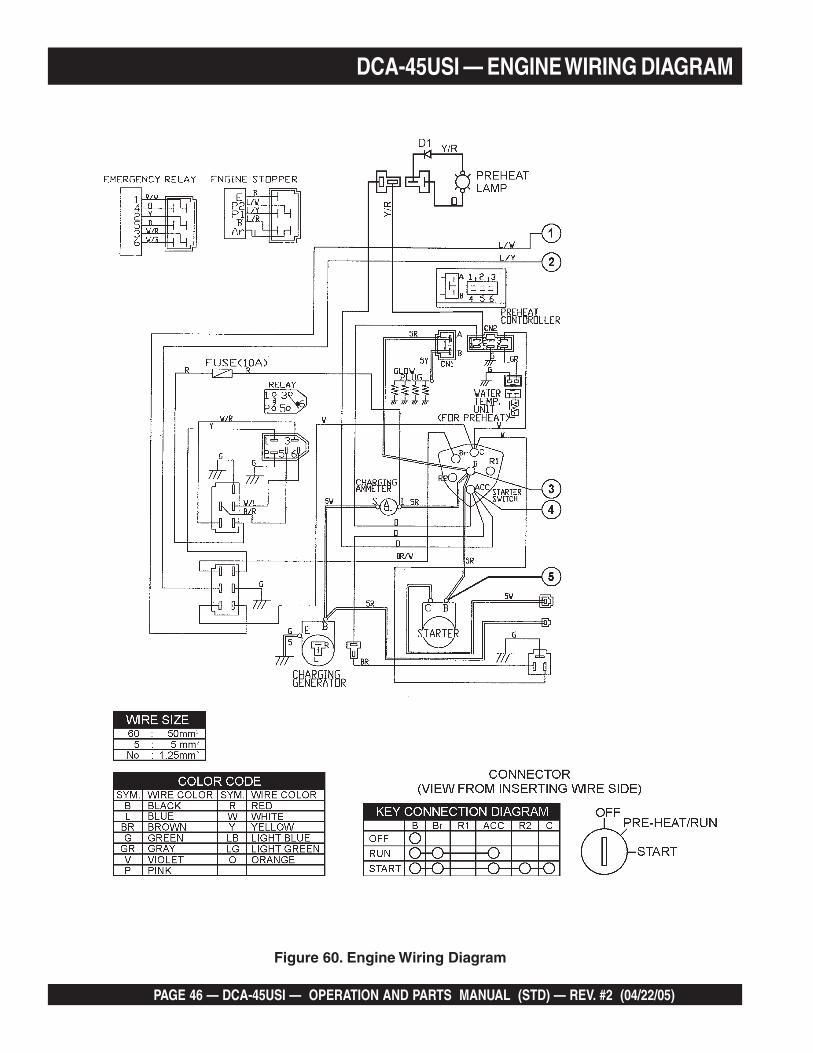
PAGE 46 — DCA-45USI — OPERATION AND PARTS MANUAL (STD) — REV. #2 (04/22/05)
DCA-45USI — ENGINE WIRING DIAGRAM
Figure 60. Engine Wiring Diagram
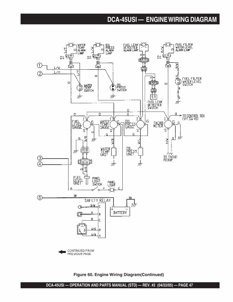
DCA-45USI — OPERATION AND PARTS MANUAL (STD) — REV. #2 (04/22/05) — PAGE 47
DCA-45USI — ENGINE WIRING DIAGRAM
Figure 60. Engine Wiring Diagram(Continued)
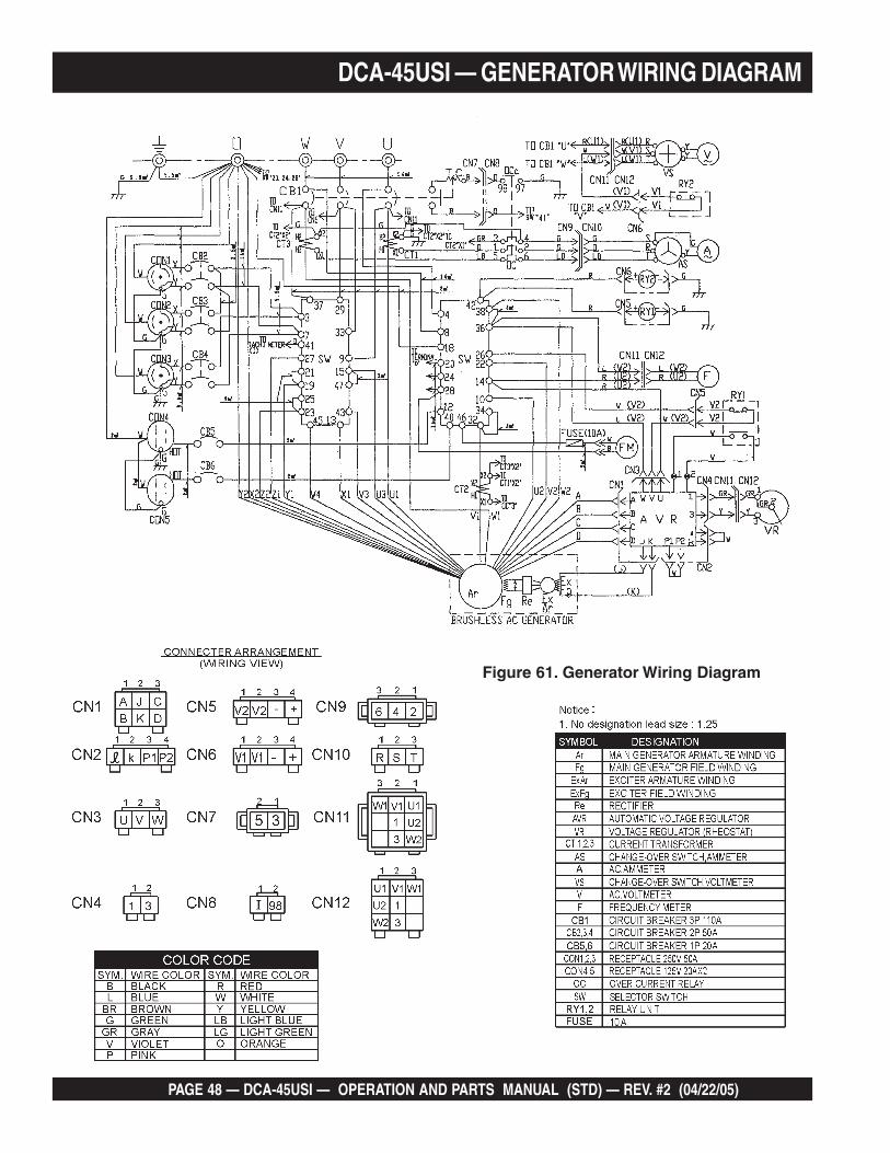
PAGE 48 — DCA-45USI — OPERATION AND PARTS MANUAL (STD) — REV. #2 (04/22/05)
DCA-45USI — GENERATOR WIRING DIAGRAM
Figure 61. Generator Wiring Diagram

DCA-45USI — OPERATION AND PARTS MANUAL (STD) — REV. #2 (04/22/05) — PAGE 49
Practically all breakdowns can be prevented by proper handling and maintenance inspections, but in the event of abreakdown, use the table (Table 19) shown below for basic Generator Troubleshooting. If the problem cannot be remedied,consult our company's business office or service plant.
DCA-45USI — TROUBLESHOOTING (GENERATOR)
GNITOOHSELBUORTROTARENEG.91ELBAT
MOTPMYS MELBORPELBISSOP NOITULOS
tuptuOegatloVoN ?evitcefedretemtloVCA .retemtlovagnisuegatlovtuptuokcehC
?esoolnoitcennocgniriwsI .riaperdnagniriwkcehC
?evitcefedRVAsI .yrassecenfiecalpeR
?reifitceRgnitatoRevitcefeD .ecalperdnakcehC
?dleiFreticxEevitcefeD 5NCnoKdnaJssorcasmho6.71rofkcehC
tuptuOegatloVwoL ?tcerrocdeepsenignesI deepstcerrocehtottsujdadnadeepsenignekcehC
?esoolsnoitcennocgniriwsI .riaperdnagniriwkcehC
?RVAevitcefeD .yrassecenfiecalpeR
tuptuOegatloVhgiH ?esoolsnoitcennocgniriwsI .riaperdnagniriwkcehC
?RVAevitcefeD .yrassecenfiecalpeR
deppirTrekaerBtiucriC ?daolnitiucriCtrohS .riaperdnadaolkcehC
?tnerrucrevO .ecuderdnastnemeriuqerdaolmrifnoC
?rekaerbtiucricevitcefeD .ecalperdnakcehC
?detautcayaleRtnerrucrevO .ecalperdnatnemeriuqerdaolmrifnoC
PAGE 50 — DCA-45USI — OPERATION AND PARTS MANUAL (STD) — REV. #2 (04/22/05)
EXPLANATION OF CODE IN REMARKS COLUMN
How to read the marks and remarks used in this partsbook.
Items Found In the “Remarks” Column
Serial Numbers-Where indicated, this indicates a serialnumber range (inclusive) where a particular part is used.
Model Number-Where indicated, this shows that thecorresponding part is utilized only with this specific modelnumber or model number variant.
Items Found In the “Items Number” Column
All parts with same symbol in the number column, *, #,+,%, or <, belong to the same assembly or kit
If more than one of the samereference number is listed, the lastone listed indicates newest (orlatest) part available.
The contents of this catalog aresubject to change without notice.
NOTE
NOTE

DCA-45USI — OPERATION AND PARTS MANUAL (STD) — REV. #2 (04/22/05) — PAGE 51
DCA-45USIw/ ISUZU BB-4JG1T
1 TO 3 UNITS
DCA-45USI — SUGGESTED SPARE PARTS
Part number on this SuggestedSpare Parts list may supercede/replace the P/N shown in the textpages of this book.
NOTE
Qty. P/N Description3 ......... 8970497081 ..............OIL FILTER3 ......... 8943692993 ..............FUEL FILTER3 ......... 0602046681 ..............AIR ELEMENT1 ......... 0602122272 ..............UNIT, OIL PRESSURE1 ......... 0602123260 ..............UNIT WATER TEMPERATURE1 ......... 8972606490 ..............FAN BELT3 ......... 8944024980 ..............KEY, STARTER SWITCH1 ......... 0605505070 ..............CAP, FUEL TANK1 ......... 9827200690 ..............SENDER, OIL PRESSURE (ENGINE SIDE)1 ......... 8970785920 ..............SENDER, WATER TEMPERATURE (ENGINE SIDE)2 ......... 0601802149 ..............FUSE, 10A

PAGE 52 — DCA-45USI — OPERATION AND PARTS MANUAL (STD) — REV. #2 (04/22/05)
DCA-45USI — GENERATOR ASSY.
GENERATOR ASSY.
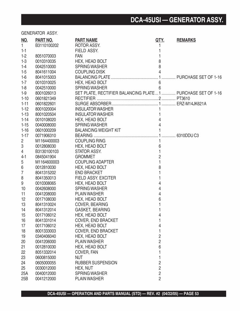
DCA-45USI — OPERATION AND PARTS MANUAL (STD) — REV. #2 (04/22/05) — PAGE 53
GENERATOR ASSY.
NO. PART NO. PART NAME QTY. REMARKS1 B3110100202 ROTOR ASSY. 11-1 FIELD ASSY. 11-2 8051070003 FAN 11-3 0010310035 HEX, HEAD BOLT 81-4 0042510000 SPRING WASHER 81-5 8041611004 COUPLING DISK 41-6 8041015003 BALANCING PLATE ............................................1 ............. PURCHASE SET OF 1-161-7 0010310025 HEX, HEAD BOLT 61-8 0042510000 SPRING WASHER 61-9 8001026013 SET PLATE, RECTIFIER BALANCING PLATE...1 ............. PURCHASE SET OF 1-161-10 0601821349 RECTIFIER .........................................................2 ............. PT36101-11 0601822601 SURGE ABSORBER ...........................................1 ............. ERZ-M14JK621A1-12 8001020004 INSULATOR WASHER 11-13 8001020504 INSULATOR WASHER 11-14 0010108020 HEX, HEAD BOLT 41-15 0040008000 SPRING WASHER 41-16 0601000209 BALANCING WEIGHT KIT 11-17 0071906310 BEARING ............................................................1 ............. 6310DDU C32 M1164400003 COUPLING RING 13 0012808030 HEX, HEAD BOLT 64 B3130100103 STATOR ASSY. 14-1 0845041904 GROMMET 25 M1164600003 COUPLING ADAPTER 16 0012810030 HEX, HEAD BOLT 87 8041315202 END BRACKET 18 8041350013 FIELD ASSY. EXCITER 19 0010308065 HEX, HEAD BOLT 410 0042608000 SPRING WASHER 411 0041208000 PLAIN WASHER 412 0017108030 HEX, HEAD BOLT 613 8041310024 COVER, BEARING 114 8041312014 GASKET, BEARING 115 0017106012 HEX, HEAD BOLT 416 8041331014 COVER, END BRACKET 117 0017106012 HEX, HEAD BOLT 418 8001333003 COVER, END BRACKET 119 0340406040 HEX, HEAD BOLT 220 0041206000 PLAIN WASHER 221 0012810030 HEX, HEAD BOLT 622 8051332014 COVER, FAN 123 0600815000 NUT 124 0605000055 RUBBER SUSPENSION 225 0030012000 HEX, NUT 225A 0040012000 SPRING WASHER 225B 0041212000 PLAIN WASHER 2
DCA-45USI — GENERATOR ASSY.
PAGE 54 — DCA-45USI — OPERATION AND PARTS MANUAL (STD) — REV. #2 (04/22/05)
DCA-45USI — CONTROL BOX ASSY.
CONTROL BOX ASSY.
DCA-45USI — OPERATION AND PARTS MANUAL (STD) — REV. #2 (04/22/05) — PAGE 55
CONTROL BOX ASSY.
NO. PART NO. PART NAME QTY. REMARKS1 M1214000102 CONTROL BOX 12 0601808825 CIRCUIT BREAKER, 3-POLE, 110A ...................1 ............. KAF3611010393 0021005080 MACHINE SCREW 44 0601823863 RELAY UNIT .......................................................2 ............. MSA9013A5 0027104016 MACHINE SCREW 46 0601820671 AUTOMATIC VOLTAGE REGULATOR..................1 ............. NTA-5A-2DB7 0027105016 MACHINE SCREW 48 0601806116 CURRENT TRANSFORMER ...............................3 ............. 812-943 75/5A9 0027106016 MACHINE SCREW 610 0601820845 OVER CURRENT RELAY ....................................1 ............. LR2D130811 0601820846 OVER CURRENT RELAY ....................................1 ............. LA7D106412 0027104016 MACHINE SCREW 212A 0207004000 HEX, NUT 213 M1213500303 CONTROL BOX COVER 114 0016906016 HEX, HEAD BOLT 415 M1201000004 SELECTOR SWITCH ..........................................1 ............. VY-4015A TBD KNOB, SELECTOR 116 M1215601204 SWITCH BRACKET 117 0027103010 MACHINE SCREW 418 0016906016 HEX, HEAD BOLT 419 0330000530 EDGING 120 M1215601104 SWITCH COVER 121 0016906016 HEX, HEAD BOLT 322 0016906016 HEX, HEAD BOLT 822A 0040506000 TOOTHED WASHER 123 M1224000003 CONTROL PANEL 124 0601807641 FREQUENCY METER ........................................1 ............. FCF-6 45~65Hz 240V25 0601808986 AC AMMETER ....................................................1 ............. ACF-6 0~75A/150A:5A26 0601801040 CHANGE-OVER SWITCH, AMMETER ...............1 ............. SL-2 AS27 0601806859 AC VOLTMETER .................................................1 ............. SCF-6 0~600V28 0601801041 CHANGE-OVER SWITCH, VOLTMETER ............1 ............. SL-2 VS
DCA-45USI — CONTROL BOX ASSY.

PAGE 56 — DCA-45USI — OPERATION AND PARTS MANUAL (STD) — REV. #2 (04/22/05)
DCA-45USI — CONTROL BOX ASSY.
CONTROL BOX ASSY.

DCA-45USI — OPERATION AND PARTS MANUAL (STD) — REV. #2 (04/22/05) — PAGE 57
CONTROL BOX ASSY.
NO. PART NO. PART NAME QTY. REMARKS29 0601840073 RHEOSTAT(VOLTAGE REGULATOR) ..................1 ........ RA20A2SE102BJ 2W 1K OHM30 0601840121 KNOB 131 0602100009 STARTER SWITCH .............................................1 ........ ISUZU 897044-418031A 8944024980 IGNITION KEY 132 0602103092 PREHEAT LAMP .................................................1 ........ PL-0532A 0601810245 BULB, E-10 T-10 DC18V 133 0602120095 TACHOMETER ....................................................1 ........ 10368034 0602122093 OIL PRESSURE GAUGE ....................................1 ........ 10017435 0602123090 WATER TEMPERATURE GAUGE .......................1 ........ 10068336 0602121080 CHARGING AMMETER ......................................1 ........ 10015837 0602125090 FUEL GAUGE......................................................1 ........ 10017638 0602103092 ALARM LAMP, PL-05 338 0602103092 ALARM LAMP, PL05 ...........................................4 ........ S/N 8200081~38A 0601810245 BULB, E-10 T-10 DC18V 338A 0601810245 BULB, E-10 T-10 DC18V ......................................4 ........ S/N 8200081~39 0601810141 PANEL LIGHT......................................................1 ........ 98268-O037040 0601831330 SWITCH, PANEL LIGHT 141 M1224100104 STOPPER 142 0027105010 MACHINE SCREW 243 0027105010 MACHINE SCREW 444 M9220100004 SET SCREW 245 0080200007 SNAP RING 246 0602200432 EMERGENCY RELAY .........................................1 ........ 897111-962147 0602202506 PREHEAT CONTROLLER ...................................1 ........ 897246-510048 0016906020 HEX, HEAD BOLT ...............................................349 0602200305 SAFETY RELAY .................................................1 ........ 182553-043050 0602201400 RELAY .................................................................1 ........ 582550-029051 0016906016 HEX, HEAD BOLT 352 0606503062 FUEL LEAK DETECTED SWITCH 153 M1414800104 BRACKET 154 0016908020 HEX, HEAD BOLT 255 M1247700114 WIRE HARNESS, GENERATOR 156 M1358200112 WIRE HARNESS, ENGINE 157 M3357200304 WIRE, HARNESS, FUEL LEAK ..........................1 ........ S/N 8200081~58 0601823223 RECTIFIER .........................................................2 ........ S/N 8200001 TO 820008058 0601823245 RECTIFIER .........................................................2 ........ S/N 8200001 TO 820008059 0601802149 FUSE, 10A ..........................................................2 ........ S/N 8200081~60 0602103092 ALARM LAMP, PL05 ...........................................4 ........ S/N 8200081~60A 0601810245 BULB, E-10 T-10 DC18V ......................................4 ........ S/N 8200081~61 06021222272 UNIT, OIL PRESSURE ........................................1 ........ 10849762 M9200100004 ADAPTER 163 0602123260 UNIT, WATER TEMPERATURE ...........................1 ........ 02094-0064 0602021109 PACKING .............................................................1 ........ 909572-0140
DCA-45USI — CONTROL BOX ASSY.
PAGE 58 — DCA-45USI — OPERATION AND PARTS MANUAL (STD) — REV. #2 (04/22/05)
ENGINE AND RADIATOR ASSY.
DCA-45USI — ENGINE AND RADIATOR ASSY.
DCA-45USI — OPERATION AND PARTS MANUAL (STD) — REV. #2 (04/22/05) — PAGE 59
ENGINE AND RADIATOR ASSY.
NO. PART NO. PART NAME QTY. REMARKS1 M1924200014 ENGINE...............................................................1 ........ ISUZU BB-4JG1T1-1 897049-7081 CARTRIDGE, OIL FILTER ...................................1 ........ REPLACES 06020412142 0605000048 RUBBER SUSPENSION 23 0030010000 HEX, NUT 24 0040010000 SPRING WASHER 25 0041210000 PLAIN WASHER 26 M1923200084 RADIATOR ...........................................................1 ........ 2951-293-00006A 0602011079 CAP, RADIATOR ..................................................1 ........ 6713-092-09017 M9312200104 MOUNT RUBBER 28 0016908040 HEX, HEAD BOLT 29 0207008000 HEX, NUT 210 M1311500003 RADIATOR HOSE 111 M1311500103 RADIATOR HOSE 112 0605515201 HOSE BAND 413 M1424700104 FAN GUARD 114 M1424700004 FAN GUARD 115 0016906016 HEX, HEAD BOLT 716 0602046582 AIR CLEANER ....................................................1 ........ FPG08-252716A 0602046681 ELEMENT, AIR CLEANER ..................................1 ........ P82-888917 0602040651 INDICATOR, AIR CLEANER ................................1 ........ RBX00-235218 M1374200104 BRACKET, AIR CLEANER 119 0602040556 BAND, AIR CLEANER 120 0016908020 HEX, HEAD BOLT 221 0207008000 HEX, NUT 222 0016910025 HEX, HEAD BOLT 223 M1374100003 HOSE, AIR CLEANER 124 M1374100103 HOSE, AIR CLEANER 125 0605515148 HOSE BAND 126 0605515200 HOSE BAND 227 0602022560 ADAPTER 128 M1320300304 PACKING 129 0602022561 90 DEG. ELBOW 130 0603306590 CONNECTOR 1
DCA-45USI — ENGINE AND RADIATOR ASSY.
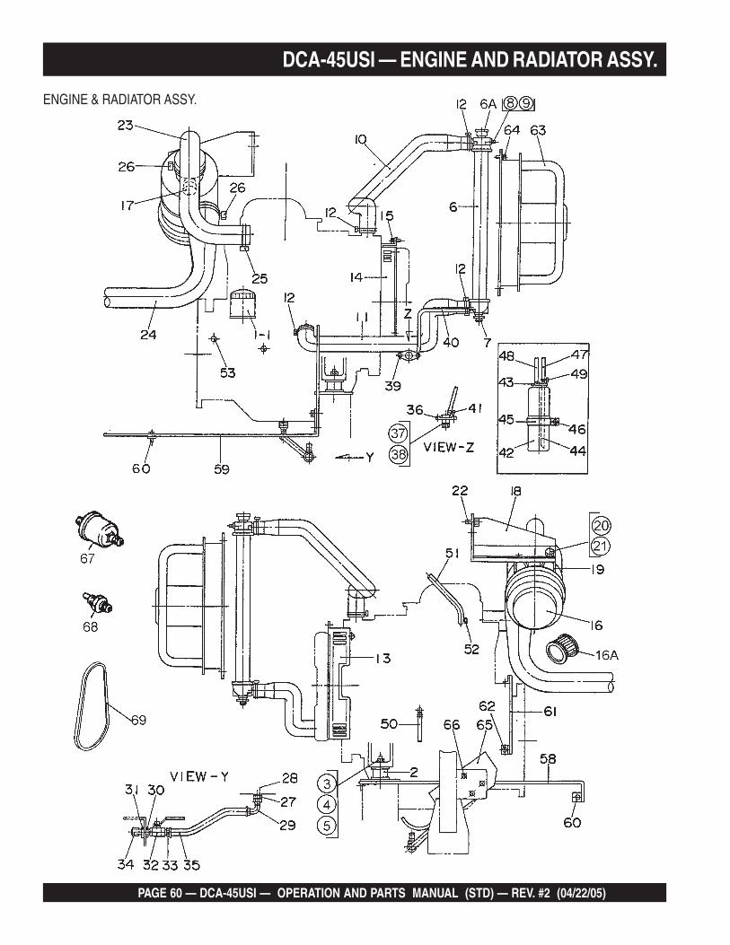
PAGE 60 — DCA-45USI — OPERATION AND PARTS MANUAL (STD) — REV. #2 (04/22/05)
ENGINE & RADIATOR ASSY.
DCA-45USI — ENGINE AND RADIATOR ASSY.
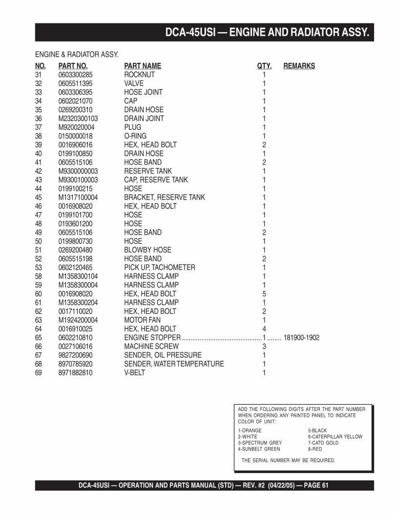
DCA-45USI — OPERATION AND PARTS MANUAL (STD) — REV. #2 (04/22/05) — PAGE 61
ENGINE & RADIATOR ASSY.
NO. PART NO. PART NAME QTY. REMARKS31 0603300285 ROCKNUT 132 0605511395 VALVE 133 0603306395 HOSE JOINT 134 0602021070 CAP 135 0269200310 DRAIN HOSE 136 M2320300103 DRAIN JOINT 137 M920020004 PLUG 138 0150000018 O-RING 139 0016906016 HEX, HEAD BOLT 240 0199100850 DRAIN HOSE 141 0605515106 HOSE BAND 242 M9300000003 RESERVE TANK 143 M9300100003 CAP, RESERVE TANK 144 0199100215 HOSE 145 M1317100004 BRACKET, RESERVE TANK 146 0016908020 HEX, HEAD BOLT 147 0199101700 HOSE 148 0193601200 HOSE 149 0605515106 HOSE BAND 250 0199800730 HOSE 151 0269200480 BLOWBY HOSE 152 0605515198 HOSE BAND 253 0602120465 PICK UP, TACHOMETER 158 M1358300104 HARNESS CLAMP 159 M1358300004 HARNESS CLAMP 160 0016908020 HEX, HEAD BOLT 561 M1358300204 HARNESS CLAMP 162 0017110020 HEX, HEAD BOLT 263 M1924200004 MOTOR FAN 164 0016910025 HEX, HEAD BOLT 465 0602210810 ENGINE STOPPER.............................................1 ........ 181900-190266 0027106016 MACHINE SCREW 367 9827200690 SENDER, OIL PRESSURE 168 8970785920 SENDER, WATER TEMPERATURE 169 8971882810 V-BELT 1
DCA-45USI — ENGINE AND RADIATOR ASSY.
THE SERIAL NUMBER MAY BE REQUIRED.
ADD THE FOLLOWING DIGITS AFTER THE PART NUMBERWHEN ORDERING ANY PAINTED PANEL TO INDICATECOLOR OF UNIT:
1-ORANGE 5-BLACK2-WHITE 6-CATERPILLAR YELLOW3-SPECTRUM GREY 7-CATO GOLD4-SUNBELT GREEN 8-RED
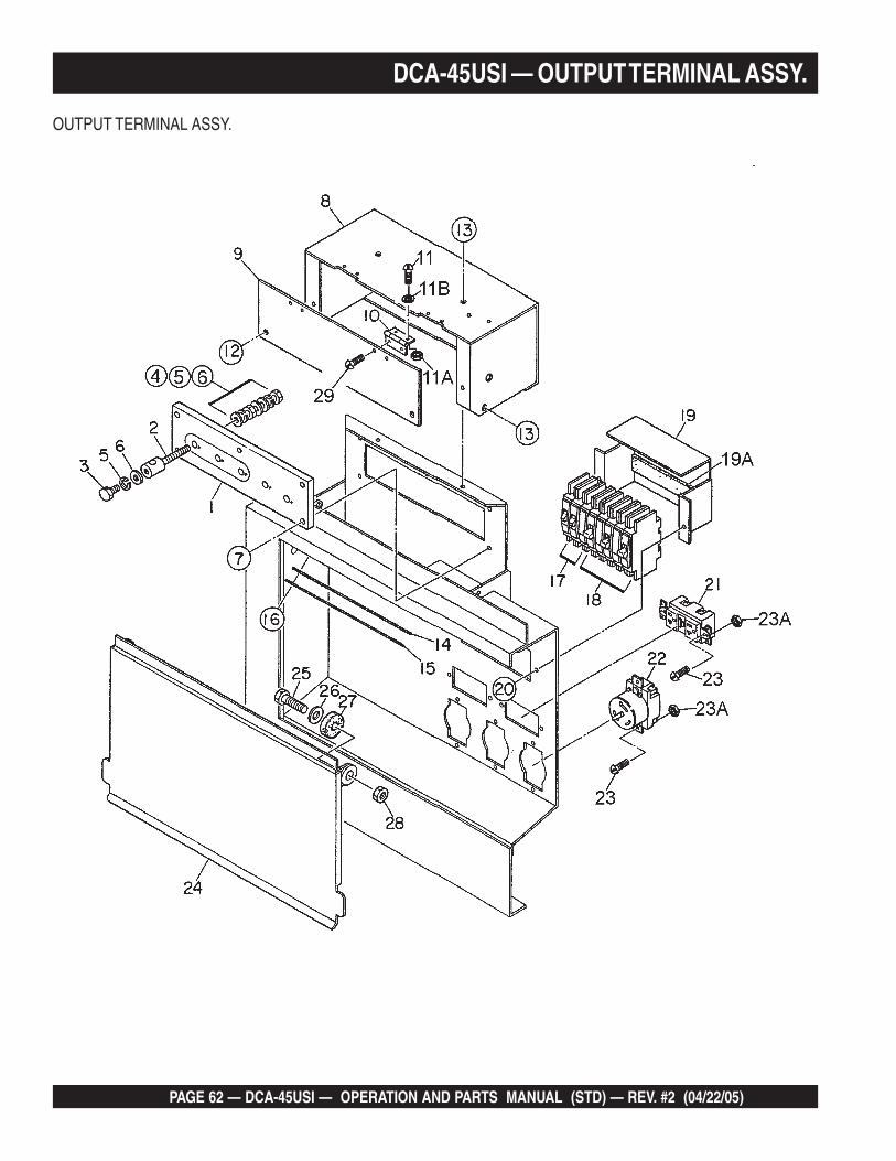
PAGE 62 — DCA-45USI — OPERATION AND PARTS MANUAL (STD) — REV. #2 (04/22/05)
DCA-45USI — OUTPUT TERMINAL ASSY.
OUTPUT TERMINAL ASSY.
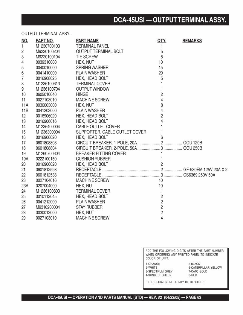
DCA-45USI — OPERATION AND PARTS MANUAL (STD) — REV. #2 (04/22/05) — PAGE 63
DCA-45USI — OUTPUT TERMINAL ASSY.
OUTPUT TERMINAL ASSY.
NO. PART NO. PART NAME QTY. REMARKS1 M1230700103 TERMINAL PANEL 12 M9220100204 OUTPUT TERMINAL BOLT 53 M9220100104 TIE SCREW 54 0039310000 HEX, NUT 105 0040010000 SPRING WASHER 156 0041410000 PLAIN WASHER 207 0016908025 HEX, HEAD BOLT 58 M1236100613 TERMINAL COVER 19 M1236100704 OUTPUT WINDOW 110 0605010040 HINGE 211 0027103010 MACHINE SCREW 411A 0030003000 HEX, NUT 811B 0041203000 PLAIN WASHER 412 0016906020 HEX, HEAD BOLT 213 0016906016 HEX, HEAD BOLT 414 M1236400004 CABLE OUTLET COVER 115 M1236300004 SUPPORTER, CABLE OUTLET COVER 116 0016906020 HEX, HEAD BOLT 617 0601808803 CIRCUIT BREAKER, 1-POLE, 20A.....................2 ................. QOU 120B18 0601808804 CIRCUIT BREAKER, 2-POLE, 50A.....................3 ................. QOU 250B19 M1260700304 BREAKER FITTING COVER 119A 0222100150 CUSHION RUBBER 120 0016906020 HEX, HEAD BOLT 221 0601812598 RECEPTACLE .....................................................2 ................. GF-530EM 125V 20A X 222 0601812538 RECEPTACLE .....................................................3 ................. CS6369 250V 50A23 0027104016 MACHINE SCREW 1023A 0207004000 HEX, NUT 1024 M1236100803 TERMINAL COVER 125 0010112045 HEX, HEAD BOLT 226 0041212000 PLAIN WASHER 227 M9310200004 STAY RUBBER 228 0030012000 HEX, NUT 229 0027103010 MACHINE SCREW 4
THE SERIAL NUMBER MAY BE REQUIRED.
ADD THE FOLLOWING DIGITS AFTER THE PART NUMBERWHEN ORDERING ANY PAINTED PANEL TO INDICATECOLOR OF UNIT:
1-ORANGE 5-BLACK2-WHITE 6-CATERPILLAR YELLOW3-SPECTRUM GREY 7-CATO GOLD4-SUNBELT GREEN 8-RED

PAGE 64 — DCA-45USI — OPERATION AND PARTS MANUAL (STD) — REV. #2 (04/22/05)
DCA-45USI — BATTERY ASSY.
BATTERY ASSY.
DCA-45USI — OPERATION AND PARTS MANUAL (STD) — REV. #2 (04/22/05) — PAGE 65
BATTERY ASSY.
NO. PART NO. PART NAME QTY. REMARKS1 0602220187 BATTERY 12 M9310500014 BATTERY SHEET 13 M9103000304 BATTERY BAND 14 0602220920 BATTERY BOLT SET 25 0040006000 SPRING WASHER 26 M1347200004 BATTERY CABLE 17 M1347200104 BATTERY CABLE 18 0016910020 HEX, HEAD BOLT 29 0040510000 TOOTHED WASHER 210 CABLE, GROUND ...............................................1 ..................... MAKE LOCALLY
DCA-45USI — BATTERY ASSY.
PAGE 66 — DCA-45USI — OPERATION AND PARTS MANUAL (STD) — REV. #2 (04/22/05)
MUFFLER ASSY.
DCA-45USI — MUFFLER ASSY.
DCA-45USI — OPERATION AND PARTS MANUAL (STD) — REV. #2 (04/22/05) — PAGE 67
MUFFLER ASSY.
NO. PART NO. PART NAME QTY. REMARKS1 M1331100102 MUFFLER 12 0017112030 HEX, HEAD BOLT 43 M1334000003 EXHAUST PIPE 14 0602320101 GASKET .............................................................1 ........ 894369-02105 0039308000 HEX, NUT 66 0602325088 SEAL CLAMP 1
DCA-45USI — MUFFLER ASSY.

PAGE 68 — DCA-45USI — OPERATION AND PARTS MANUAL (STD) — REV. #2 (04/22/05)
DCA-45USI — FUEL TANK ASSY.
FUEL TANK ASSY.
DCA-45USI — OPERATION AND PARTS MANUAL (STD) — REV. #2 (04/22/05) — PAGE 69
DCA-45USI — FUEL TANK ASSY.
FUEL TANK ASSY.
NO. PART NO. PART NAME QTY. REMARKS1 M1364000102 FUEL TANK 11A 0605505070 FUEL TANK CAP 11B 0605501072 FUEL SENDER UNIT 11C 0605516090 GASKET 12 M1364200004 TANK BAND 43 M9310500104 SUPPORTER SHEET 44 0016908020 HEX, HEAD BOLT 45 0016908065 HEX, HEAD BOLT 25A 0207008000 HEX, NUT 66 0191301300 VENT HOSE 17 0605515109 HOSE BAND 28 897211-2730 FUEL FILTER ......................................................1 ........ REPLACES 06020422038A 897213-4720 CARTRIDGE, FUEL FILTER ...............................1 ........ REPLACES 06020427019 M1367700004 BRACKET, FUEL FILTER 110 0016908020 HEX, HEAD BOLT 411 0191200550 SUCTION HOSE 112 0191201600 SUCTION HOSE 113 0605515108 HOSE BAND 414 0191300750 RETURN HOSE 115 0605515109 HOSE BAND 215 0222100700 TANK SHEET 5
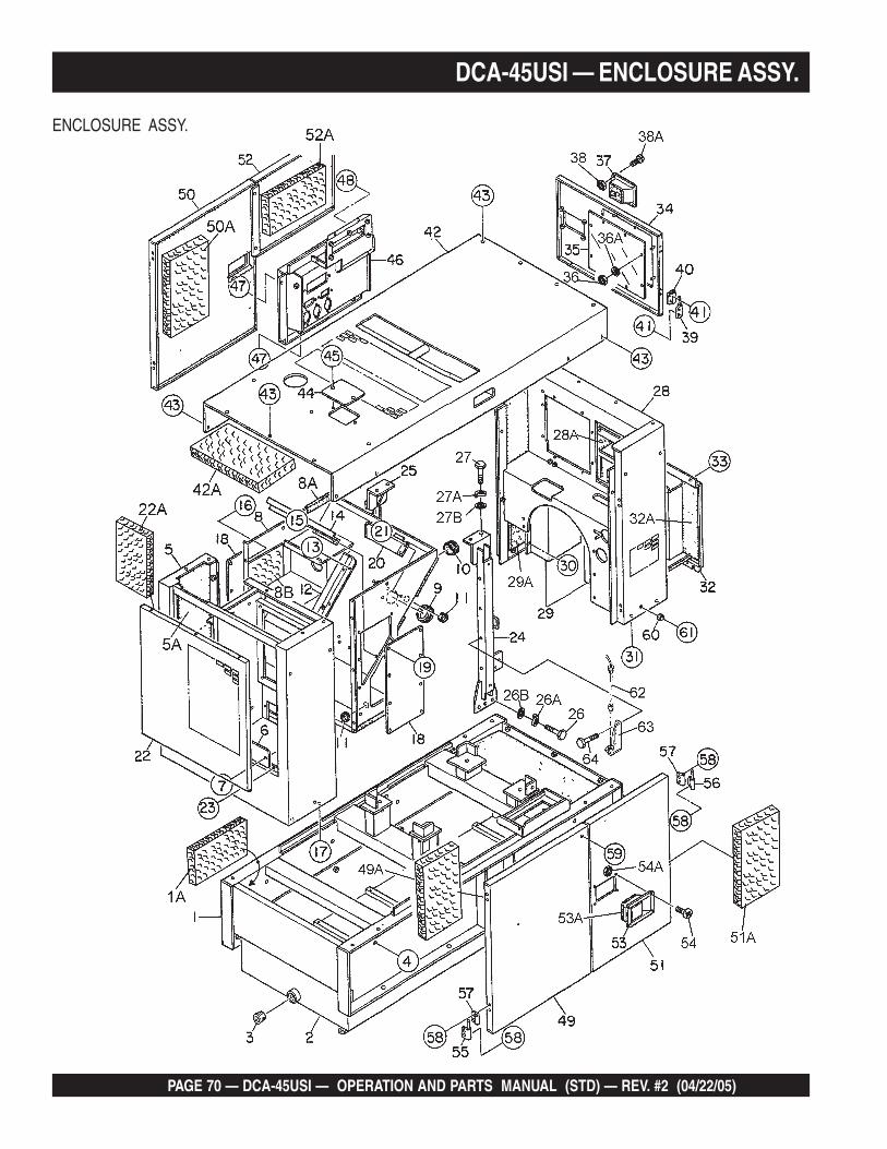
PAGE 70 — DCA-45USI — OPERATION AND PARTS MANUAL (STD) — REV. #2 (04/22/05)
DCA-45USI — ENCLOSURE ASSY.
ENCLOSURE ASSY.
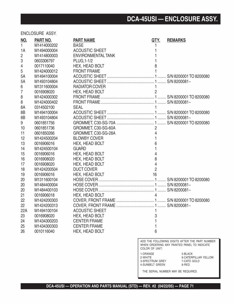
DCA-45USI — OPERATION AND PARTS MANUAL (STD) — REV. #2 (04/22/05) — PAGE 71
DCA-45USI — ENCLOSURE ASSY.
ENCLOSURE ASSY.
NO. PART NO. PART NAME QTY. REMARKS1 M1414000202 BASE 11A M1494000004 ACOUSTIC SHEET 12 M1414800003 ENVIRONMENTAL TANK 13 0603306797 PLUG,1-1/2 14 0017110040 HEX, HEAD BOLT 85 M1424000012 FRONT FRAME 15A M1494100004 ACOUSTIC SHEET .............................................1 ........ S/N 8200001 TO 82000805A M1493104804 ACOUSTIC SHEET .............................................1 ........ S/N 8200081~6 M1311600004 RADIATOR COVER 17 0016908020 HEX, HEAD BOLT 28 M1424000302 FRONT FRAME...................................................1 ........ S/N 8200001 TO 82000808 M1424000402 FRONT FRAME...................................................1 ........ S/N 8200081~8A 0314502100 SEAL 18B M1494100004 ACOUSTIC SHEET .............................................1 ........ S/N 8200001 TO 82000808B M1493104804 ACOUSTIC SHEET .............................................1 ........ S/N 8200081~9 0601851756 GROMMET, C30-SG-70A ....................................1 ........ S/N 8200001 TO 820008010 0601851736 GROMMET, C30-SG-60A 211 0601850266 GROMMET, C30-SG-28A 412 M1424500204 BLOWBY COVER 113 0016906016 HEX, HEAD BOLT 614 M1424500104 GUARD 115 0016906016 HEX, HEAD BOLT 416 0016908020 HEX, HEAD BOLT 817 0016908020 HEX, HEAD BOLT 418 M1424200504 DUCT COVER 219 0016906016 HEX, HEAD BOLT 1620 M1311600104 HOSE COVER .....................................................1 ........ S/N 8200001 TO 820008020 M1484400004 HOSE COVER .....................................................1 ........ S/N 8200081~20 M1484400103 HOSE COVER .....................................................1 ........ S/N 8200081~21 0016906018 HEX, HEAD BOLT 422 M1424200303 COVER, FRONT FRAME ....................................1 ........ S/N 8200001 TO 820008022 M1424200313 COVER, FRONT FRAME ....................................1 ........ S/N 8200081~22A M1494100104 ACOUSTIC SHEET 123 0016908020 HEX, HEAD BOLT 324 M1434300203 CENTER FRAME 125 M1434300303 CENTER FRAME 126 0010116040 HEX, HEAD BOLT 6
THE SERIAL NUMBER MAY BE REQUIRED.
ADD THE FOLLOWING DIGITS AFTER THE PART NUMBERWHEN ORDERING ANY PAINTED PANEL TO INDICATECOLOR OF UNIT:
1-ORANGE 5-BLACK2-WHITE 6-CATERPILLAR YELLOW3-SPECTRUM GREY 7-CATO GOLD4-SUNBELT GREEN 8-RED
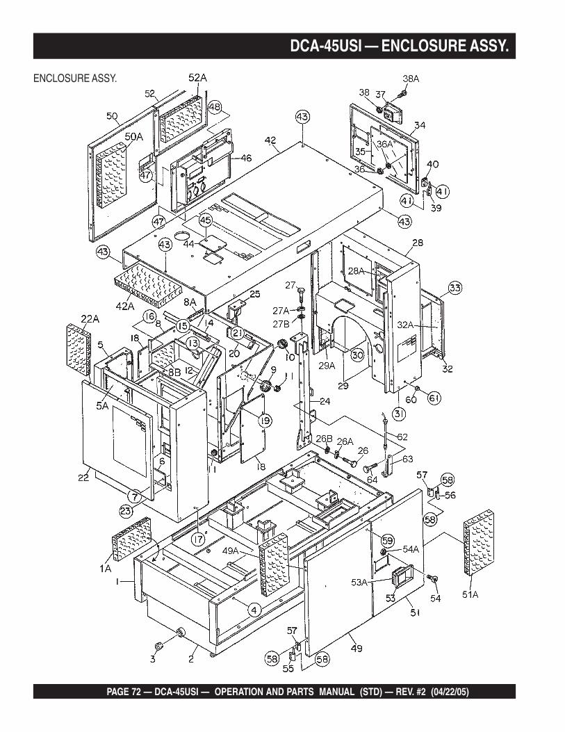
PAGE 72 — DCA-45USI — OPERATION AND PARTS MANUAL (STD) — REV. #2 (04/22/05)
DCA-45USI — ENCLOSURE ASSY.
ENCLOSURE ASSY.
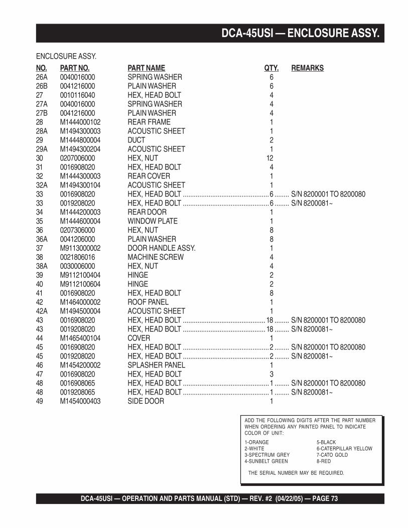
DCA-45USI — OPERATION AND PARTS MANUAL (STD) — REV. #2 (04/22/05) — PAGE 73
ENCLOSURE ASSY.
NO. PART NO. PART NAME QTY. REMARKS26A 0040016000 SPRING WASHER 626B 0041216000 PLAIN WASHER 627 0010116040 HEX, HEAD BOLT 427A 0040016000 SPRING WASHER 427B 0041216000 PLAIN WASHER 428 M1444000102 REAR FRAME 128A M1494300003 ACOUSTIC SHEET 129 M1444800004 DUCT 229A M1494300204 ACOUSTIC SHEET 130 0207006000 HEX, NUT 1231 0016908020 HEX, HEAD BOLT 432 M1444300003 REAR COVER 132A M1494300104 ACOUSTIC SHEET 133 0016908020 HEX, HEAD BOLT ...............................................6 ........ S/N 8200001 TO 820008033 0019208020 HEX, HEAD BOLT ...............................................6 ........ S/N 8200081~34 M1444200003 REAR DOOR 135 M1444600004 WINDOW PLATE 136 0207306000 HEX, NUT 836A 0041206000 PLAIN WASHER 837 M9113000002 DOOR HANDLE ASSY. 138 0021806016 MACHINE SCREW 438A 0030006000 HEX, NUT 439 M9112100404 HINGE 240 M9112100604 HINGE 241 0016908020 HEX, HEAD BOLT 842 M1464000002 ROOF PANEL 142A M1494500004 ACOUSTIC SHEET 143 0016908020 HEX, HEAD BOLT ............................................. 18 ........ S/N 8200001 TO 820008043 0019208020 HEX, HEAD BOLT ............................................. 18 ........ S/N 8200081~44 M1465400104 COVER 145 0016908020 HEX, HEAD BOLT ...............................................2 ........ S/N 8200001 TO 820008045 0019208020 HEX, HEAD BOLT ...............................................2 ........ S/N 8200081~46 M1454200002 SPLASHER PANEL 147 0016908020 HEX, HEAD BOLT 348 0016908065 HEX, HEAD BOLT ...............................................1 ........ S/N 8200001 TO 820008048 0019208065 HEX, HEAD BOLT ...............................................1 ........ S/N 8200081~49 M1454000403 SIDE DOOR 1
DCA-45USI — ENCLOSURE ASSY.
THE SERIAL NUMBER MAY BE REQUIRED.
ADD THE FOLLOWING DIGITS AFTER THE PART NUMBERWHEN ORDERING ANY PAINTED PANEL TO INDICATECOLOR OF UNIT:
1-ORANGE 5-BLACK2-WHITE 6-CATERPILLAR YELLOW3-SPECTRUM GREY 7-CATO GOLD4-SUNBELT GREEN 8-RED
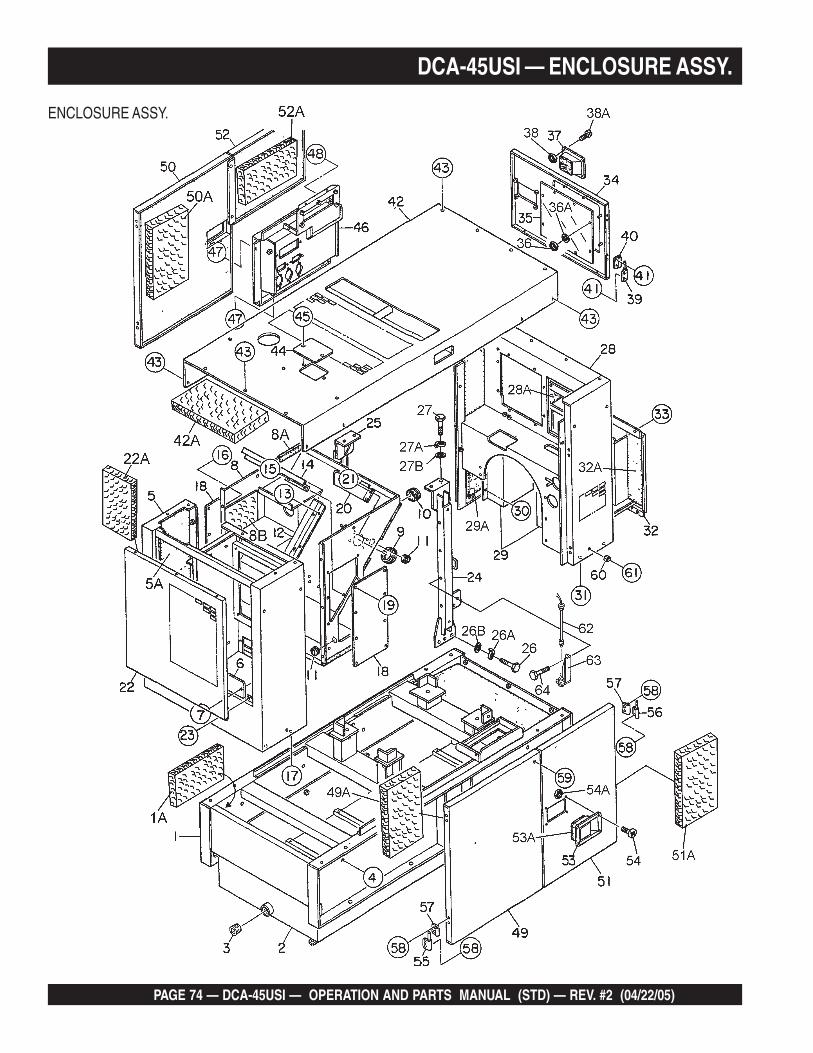
PAGE 74 — DCA-45USI — OPERATION AND PARTS MANUAL (STD) — REV. #2 (04/22/05)
DCA-45USI — ENCLOSURE ASSY.
ENCLOSURE ASSY.
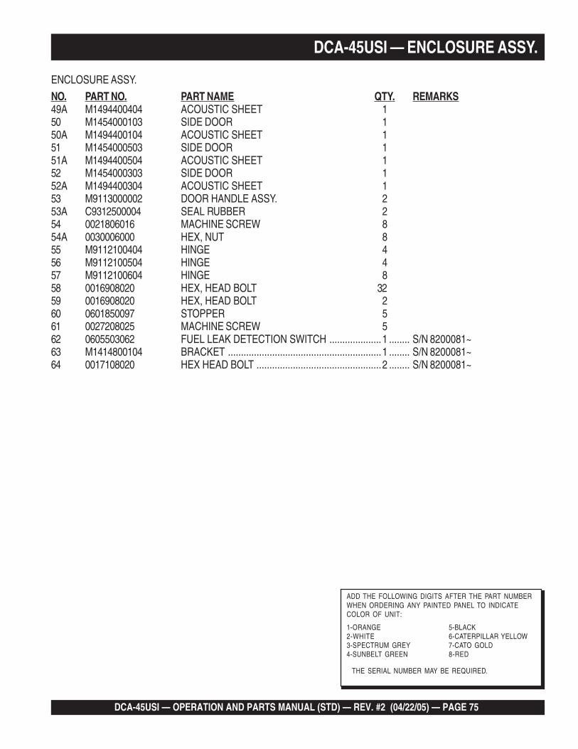
DCA-45USI — OPERATION AND PARTS MANUAL (STD) — REV. #2 (04/22/05) — PAGE 75
ENCLOSURE ASSY.
NO. PART NO. PART NAME QTY. REMARKS49A M1494400404 ACOUSTIC SHEET 150 M1454000103 SIDE DOOR 150A M1494400104 ACOUSTIC SHEET 151 M1454000503 SIDE DOOR 151A M1494400504 ACOUSTIC SHEET 152 M1454000303 SIDE DOOR 152A M1494400304 ACOUSTIC SHEET 153 M9113000002 DOOR HANDLE ASSY. 253A C9312500004 SEAL RUBBER 254 0021806016 MACHINE SCREW 854A 0030006000 HEX, NUT 855 M9112100404 HINGE 456 M9112100504 HINGE 457 M9112100604 HINGE 858 0016908020 HEX, HEAD BOLT 3259 0016908020 HEX, HEAD BOLT 260 0601850097 STOPPER 561 0027208025 MACHINE SCREW 562 0605503062 FUEL LEAK DETECTION SWITCH ....................1 ........ S/N 8200081~63 M1414800104 BRACKET ...........................................................1 ........ S/N 8200081~64 0017108020 HEX HEAD BOLT ................................................2 ........ S/N 8200081~
DCA-45USI — ENCLOSURE ASSY.
THE SERIAL NUMBER MAY BE REQUIRED.
ADD THE FOLLOWING DIGITS AFTER THE PART NUMBERWHEN ORDERING ANY PAINTED PANEL TO INDICATECOLOR OF UNIT:
1-ORANGE 5-BLACK2-WHITE 6-CATERPILLAR YELLOW3-SPECTRUM GREY 7-CATO GOLD4-SUNBELT GREEN 8-RED
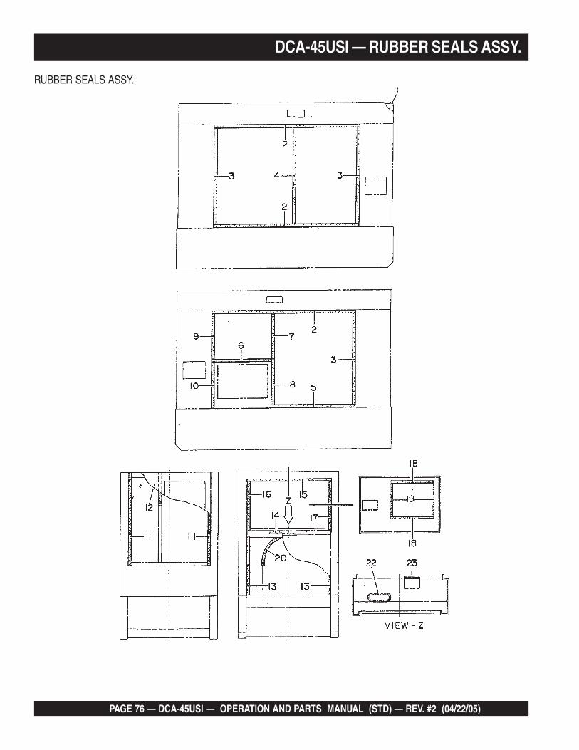
PAGE 76 — DCA-45USI — OPERATION AND PARTS MANUAL (STD) — REV. #2 (04/22/05)
DCA-45USI — RUBBER SEALS ASSY.
RUBBER SEALS ASSY.

DCA-45USI — OPERATION AND PARTS MANUAL (STD) — REV. #2 (04/22/05) — PAGE 77
DCA-45USI — RUBBER SEALS ASSY.
RUBBER SEALS ASSY.
NO. PART NO. PART NAME QTY. REMARKS1 0229200950 SEAL RUBBER 12 0228901385 SEAL RUBBER 33 0228900900 SEAL RUBBER 34 0229400900 SEAL RUBBER 15 0228900795 SEAL RUBBER 16 0028900590 SEAL RUBBER 17 0229400445 SEAL RUBBER 18 0228800455 SEAL RUBBER 19 0228900445 SEAL RUBBER 110 0229200455 SEAL RUBBER 111 0228100870 SEAL RUBBER 212 0229200840 SEAL RUBBER 113 0229200560 SEAL RUBBER 214 0229200790 SEAL RUBBER 115 0228800800 SEAL RUBBER ...................................................1 ........ S/N 8200001 TO 820008015 0228800800 SEAL RUBBER ...................................................2 ........ S/N 8200081~16 0228900475 SEAL RUBBER ...................................................1 ........ S/N 8200001 TO 820008016 0228900470 SEAL RUBBER ...................................................1 ........ S/N 8200081~17 0228800475 SEAL RUBBER ...................................................1 ........ S/N 8200001 TO 820008017 0228800470 SEAL RUBBER ...................................................1 ........ S/N 8200081~18 0228100420 SEAL RUBBER 219 0228100325 SEAL RUBBER 220 0314500700 SEAL 122 0330000460 EDGING 123 0330000180 EDGING 1
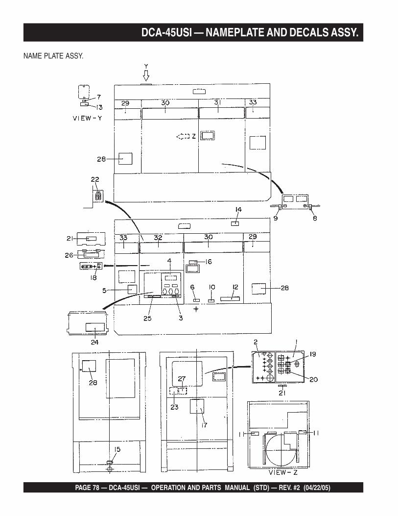
PAGE 78 — DCA-45USI — OPERATION AND PARTS MANUAL (STD) — REV. #2 (04/22/05)
DCA-45USI — NAMEPLATE AND DECALS ASSY.
NAME PLATE ASSY.
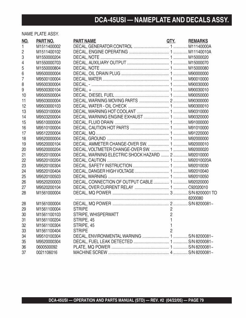
DCA-45USI — OPERATION AND PARTS MANUAL (STD) — REV. #2 (04/22/05) — PAGE 79
DCA-45USI — NAMEPLATE AND DECALS ASSY.
NAME PLATE ASSY.
NO. PART NO. PART NAME QTY. REMARKS1 M1511400002 DECAL, GENERATOR CONTROL ................................ 1 ............. M11140000A2 M1511400102 DECAL, ENGINE OPERATING .................................... 1 ............. M11140010A3 M1550000204 DECAL, NOTE .............................................................. 1 ............. M150000204 M1550000703 DECAL, AUXILIARY OUTPUT ...................................... 1 ............. M150000705 M1550000804 DECAL, NOTE .............................................................. 1 ............. M150000806 M9500000004 DECAL, OIL DRAIN PLUG ........................................... 1 ............. M900000007 M9500100004 DECAL, WATER ............................................................ 1 ............. M900100008 M9500300004 DECAL, - ...................................................................... 1 ............. M900300009 M9500300104 DECAL, + ..................................................................... 1 ............. M9003001010 M9500500004 DECAL, DIESEL FUEL ................................................. 1 ............. M9005000011 M9503000004 DECAL, WARNING MOVING PARTS ........................... 2 ............. M9030000012 M9503000103 DECAL, WATER - OIL CHECK ..................................... 1 ............. M9030001013 M9503100004 DECAL, WARNING HOT COOLANT ............................. 1 ............. M9031000014 M9503200004 DECAL, WARNING ENGINE EXHAUST ....................... 1 ............. M9032000015 M9510000004 DECAL, FLUID DRAIN ................................................. 1 ............. M9100000016 M9510100004 DECAL, CAUTION HOT PARTS ................................... 1 ............. M9101000017 M9512200004 DECAL, MQ .................................................................. 1 ............. M9122000018 M9520000004 DECAL, GROUND ........................................................ 1 ............. M9200000019 M9520000104 DECAL, AMMETER CHANGE-OVER SW. ................... 1 ............. M9200001020 M9520000204 DECAL, VOLTMETER CHANGE-OVER SW. ................ 1 ............. M9200002021 M9520100004 DECAL, WARNING ELECTRIC SHOCK HAZARD ....... 2 ............. M9201000022 M9520100204 DECAL, CAUTION ........................................................ 1 ............. M92010020A23 M9520100304 DECAL, SAFETY INSTRUCTION................................. 1 ............. M9201003024 M9520100404 DECAL, DANGER HIGH VOLTAGE ............................... 1 ............. M9201004025 M9520100503 DECAL, WARNING ....................................................... 1 ............. M9201005026 M9520200003 DECAL, CONNECTION OF OUTPUT CABLE .............. 1 ............. M9202000027 M9520200104 DECAL, OVER CURRENT RELAY ............................... 1 ............. C9202001028 M1561000004 DECAL, MQ POWER ................................................... 3 ............. S/N 8200001 TO
...................................................................................................... 820008028 M1561000004 DECAL, MQ POWER ................................................... 2 ............. S/N 8200081~29 M1561100004 STRIPE 230 M1561100103 STRIPE, WHISPERWATT 231 M1561100204 STRIPE, 45 132 M1561100304 STRIPE, 45 133 M1561100404 STRIPE 234 M9510100304 DECAL, ENVIRONMENTAL WARNING ........................ 1 ............. S/N 8200081~35 M9520000304 DECAL, FUEL LEAK DETECTED ................................ 1 ............. S/N 8200081~36 0600500092 PLATE, MQ POWER .................................................... 1 ............. S/N 8200081~37 0021106016 MACHINE SCREW ....................................................... 4 ............. S/N 8200081~
PAGE 80 — DCA-45USI — OPERATION AND PARTS MANUAL (STD) — REV. #2 (04/22/05)
TERMS AND CONDITIONS OF SALE — PARTS
PAYMENT TERMS
Terms of payment for parts are net 10 days.
FREIGHT POLICY
All parts orders will be shipped collect orprepaid with the charges added to the invoice.All shipments are F.O.B. point of origin.Multiquip’s responsibility ceases when a signedmanifest has been obtained from the carrier,and any claim for shortage or damage must besettled between the consignee and the carrier.
MINIMUM ORDER
The minimum charge for orders from Multiquipis $15.00 net. Customers will be asked forinstructions regarding handling of orders notmeeting this requirement.
RETURNED GOODS POLICY
Return shipments will be accepted and creditwill be allowed, subject to the following provi-sions:
1. A Returned Material Authorization mustbe approved by Multiquip prior to ship-ment.
2. To obtain a Return Material Authorization,a list must be provided to Multiquip PartsSales that defines item numbers, quanti-ties, and descriptions of the items to bereturned.
a. The parts numbers and descriptionsmust match the current parts pricelist.
b. The list must be typed or computergenerated.
c. The list must state the reason(s) forthe return.
d. The list must reference the salesorder(s) or invoice(s) under which theitems were originally purchased.
e. The list must include the name andphone number of the person request-ing the RMA.
3. A copy of the Return Material Authoriza-tion must accompany the return shipment.
4. Freight is at the sender’s expense. Allparts must be returned freight prepaid toMultiquip’s designated receiving point.
5. Parts must be in new and resalablecondition, in the original Multiquip pack-age (if any), and with Multiquip partnumbers clearly marked.
6. The following items are not returnable:
a. Obsolete parts. (If an item is in theprice book and shows as beingreplaced by another item, it isobsolete.)
b. Any parts with a limited shelf life(such as gaskets, seals, “O” rings,and other rubber parts) that werepurchased more than six monthsprior to the return date.
c. Any line item with an extended dealernet price of less than $5.00.
d. Special order items.
e. Electrical components.
f. Paint, chemicals, and lubricants.
g. Decals and paper products.
h. Items purchased in kits.
7. The sender will be notified of anymaterial received that is not acceptable.
8. Such material will be held for fiveworking days from notification, pendinginstructions. If a reply is not receivedwithin five days, the material will bereturned to the sender at his expense.
9. Credit on returned parts will be issued atdealer net price at time of the originalpurchase, less a 15% restocking charge.
10. In cases where an item is accepted, forwhich the original purchase documentcan not be determined, the price will bebased on the list price that was effectivetwelve months prior to the RMA date.
11. Credit issued will be applied to futurepurchases only.
PRICING AND REBATES
Prices are subject to change without priornotice. Price changes are effective on a spe-cific date and all orders received on or afterthat date will be billed at the revised price.
Rebates for price declines and added chargesfor price increases will not be made for stockon hand at the time of any price change.
Multiquip reserves the right to quote and selldirect to Government agencies, and to OriginalEquipment Manufacturer accounts who useour products as integral parts of their ownproducts.
SPECIAL EXPEDITING SERVICE
A $35.00 surcharge will be added to the invoicefor special handling including bus shipments,insured parcel post or in cases where Multiquipmust personally deliver the parts to the carrier.
LIMITATIONS OF SELLER’S LIABILITY
Multiquip shall not be liable here under fordamages in excess of the purchase price of theitem with respect to which damages are claimed,and in no event shall Multiquip be liable for lossof profit or good will or for any other special,consequential or incidental damages.
LIMITATION OF WARRANTIES
No warranties, express or implied, are made inconnection with the sale of parts or trade acces-sories nor as to any engine not manufacturedby Multiquip. Such warranties made in connec-tion with the sale of new, complete units aremade exclusively by a statement of warrantypackaged with such units, and Multiquip nei-ther assumes not authorizes any person toassume for it any other obligation or liabilitywhatever in connection with the sale of itsproducts. Apart from such written statement ofwarranty, there are no warranties, express,implied or statutory, which extend beyond thedescription of the products on the face hereof.
Effective: October 1, 2002

DCA-45USI — OPERATION AND PARTS MANUAL (STD) — REV. #2 (04/22/05) — PAGE 81
NOTE PAGE
PARTS AND OPERATION MANUALOPERATION AND PARTS MANUAL
Your Local Dealer is:MQ POWERA Division of Multiquip Inc.POST OFFICE BOX 6254CARSON, CA 90749310-537-3700 • 800-421-1244FAX: 310-632-2656E-mail: [email protected]: www.mqpower.com
HERE'S HOW TO GET HELPPLEASE HAVE THE MODEL AND SERIAL
NUMBER ON-HAND WHEN CALLINGMQ POWER CORPORATE OFFICE18910 Wilmington Ave. 800-421-1244Carson, CA 90746 FAX: 310-632-2656Email: [email protected]: www.mqpower.comPARTS DEPARTMENT800-427-1244 FAX: 800-672-7877310-537-3700 FAX: 310-637-3284SERVICE DEPARTMENT800-835-2551 FAX: 310-638-8046310-537-3700TECHNICAL ASSISTANCE800-478-1244 FAX: 310-631-5032WARRANTY DEPARTMENT800-835-2551, EXT. 279 FAX: 310-638-8046310-537-3700, EXT. 279
Manufactured for Multiquip Inc.by
DENYO CO., LTD, JAPAN