Embed Size (px)
Citation preview
c
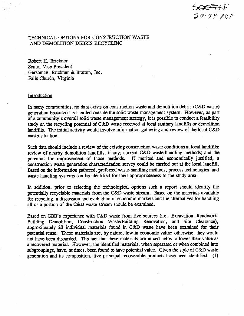
TECHNICAL OPTIONS FOR CONSTRUCTION WASTE AND DEMOLITION DEBRIS RECYCLING
Robert H. Brickner Senior Vice President Gershman, Brickner & Bratton, Inc. Falls Church, Virginia
Introduction
In many communities, no data exists on construction waste and demolition debris (C&D waste) generation because it is handled outside the solid waste management system. However, as part of a community’s ovefall solid waste management strategy, it is possible to conduct a feasibility study on the recycling potential of C&D waste received at local sanitary landfills or demolition landfas. The initial activity would involve information-gathering and review of the local C&D waste situation.
Such data should include a review of the existing construction waste conditions at local landfills; review of nearby demolition landfills, if any; current C&D waste-handling methods; and the potential for improvement of those methods. If merited and economically justified, a construction waste generation characterization survey could be carried out at the local landfill. Based on the information gathered, preferred waste-handling methods, process technologies, and waste-handling systems can be identified for their appropriateness to the study area.
In addition, prior to selecting the technological options such a report should identify the potentially recyclable materials from the C&D waste stream. Based on the materials available for recycling, a discussion and evaluation of economic markets and the alternatives for handling all or a portion of the C&D waste stream should be examined.
Based on GBB’s experience with C&D waste from five sources (Le., Excavation, Roadwork, Building Demolition, Construction Waste/Building Renovation, and Site Clearance), approximately 20 individual materials found in C&D waste have been examined for their potential reuse. These materials are, by nature, low in economic value; otherwise, they would not have been discarded. The fact that these materials are mixed helps to lower their value as a recovered material. However, the identified materials, when separated or when combined into subgroupings, have, at times, been found to have potential value. Given the style of C&D waste generation and its composition, five principal recoverable products have been identified: (1)
asphalt pavement; (2) aggregate; (3) dirt-like; (4) ferrous metal; and (5) shredded wood. Each of these products are recoverable and reusable when properly processed to user (market) requirements.
The five recoverable products presented above can be aggregated into three basic categories of recoverable materials which, depending upon the nature of the C&D waste generating base, have been shown in at least one study to comprise more than 95 percent of the local C&D waste stream. These categories are:
0 Shredded wood products; and 0 - Ferrous metal.
Inert granular material (aggregate, asphalt, and dirt-like);
In many parts of the country, no companies are commercially recycling C&D wastes. Depending upon state regulatory controls, C&D landfills, if permitted differently from conventional sanitary landfills, are typically faced with less stringent environmental regulations. Consequently, there may be no established uses of commercially recycled C&D waste materials, and, therefore, no identifiable established markets. The markets discussion may then focus on identifying potential markets and potential market values versus fitting into a more well- established product niche (e.g., the aluminum beverage can recycling programs associated with residential waste stream recyclables). The objective must be, therefore, to add maximum value to the products removed from the overall waste stream during the processing of as much of the overall material as deemed to be economically viable. Some recovered products wil l have higher intrinsic value than others; however, this value will only be realized if the market for the product exists within economic transport distance, and if the incremental cost of producing the higher value product is less than the incremental higher value of the virgin material being displaced.
I
:
C&D Waste Processing Alternatives
1. Introduction
In highlighting technical alternatives for this paper, the review will focus on the design of C&D waste processing technologies that have been designed to produce distinct product streams from a heterogeneous C&D waste stream. Many modem facilities of this sort exist as solid waste processing plants in the United States and in Europe, including the Fresh Kills Landfill crushinglscreening plant on Stabn Island, New York; the Star Recycling Facility in Brooklyn, New York; and the Basoray Plant in Basel, Switzerland. The principal C&D waste processing plant techniques covered in this paper consist primarily of the following two plant types:
0 Mixed C&D waste. RockKoncretdAsphalt crushing and screening plants; and
2. Rock Crushing Plants
The two principal size-reduction unit processes used at typical rock crushing plants are jaw crushers and cone crushers. The jaw crusher is the most universally applicable primary crusher. As a general rule, discharge material is twice the size of the crusher setting; the output gradation is also changed by closing or opening the discharge setting. Cone crushers have the same universal acceptance for secondary crushing as jaw crushers do for primary work. Standard cone crushers with a reduction ratio of 6-8 to 1 can reduce material to a minimum size of less than 314 inch.
The use of rock-crushing and sizing equipment is known and proven around the world, and a plethora of equipment manufacturers have years of experience with the equipment to draw upon. Several complementary pieces of equipment (e.g., the primary crusher feeder, magnetic separator, vibrating screens for product sizing, and several belt conveyors) form a rock- processing system. The existence of hundreds of rock quarries in the United States provides local and experienced equipment owners and operators in most regions of the country.
Based upon the waste quantification and characterization data completed by GBB on a recent C&D waste recycling study, approximately 30 percent of the Excavated Material category was classified as rock, accounting for more than 45 percent of the total rock identified in the five waste categories that were selected. Based upon the data that may be collected during C&D waste-characterization activities, it may be possible to target the processing of only the Excavated Material waste fraction. In the above-cited example, this allowed processing access to almost half of the total rock quantity projected to be available in the entire C&D waste stream of t!e study area.
3. Conciete Crushing Plants
The popularity of concrete recycling has continued to rise throughout most of the developed world. Three primary benefits are stimulating this interest: (1) saving landfill space; (2) conserving virgin materials that are being depleted in some areas (these have some unique product applications); and (3) saving money.
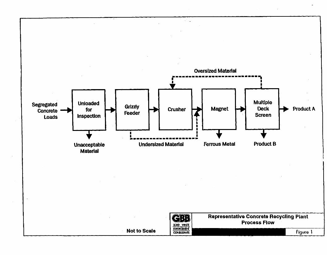
The process flow of a concrete recycling plant which, is similar to that of the rock processing plant, is shown in Figure 1'. Depending upon the type of concrete demolition taking place, the thickness of the concrete slabs, the shape of the concrete pieces, and the amount of non-concrete contamination will vary. The demolition of major old concrete highways, for example, could have very large surface area slabs, but at a predictable thickness. However, a concrete- reinforced building replacement may encounter a myriad of thicknesses and shapes. Depending
Figures 1-6 are located at the end of the text.
upon the physical shapes of the products, additional downsizing (using jackhammers) may be needed. Additionally, most crusher systems have a special-purpose jackhammer mounted at the feeder/crusher interface point to enhance reduction of large concrete pieces that were missed during the initial visual inspection and have infiltrated the feeder system. The plant operator, typically, is positioned to see the choke point jam and to jackhammer the concrete piece at that point.
Most concrete recycling plants use jaw crushers as their primary crushers. The reasons for this are: high reliability, low maintenance costs, and greater particle size control. A secondary crusher (e.g., a cone crusher) may be used for more precise and fine product sizing at concrete recycling plants. If a secondary machine is not used, a conveyor, used to carry back or recycle the oversized screened products, is employed to control the product's top size (see Figure 1).
The overall data collected on concrete and reinforced concrete availability in the five waste categories classified at a recent GBB C&D waste recycling study activity indicated that, based upon quantification and characterization data, approximately 40 percent of the weight of the Roadwork Material category was concrete, accounting for approximately 20 percent of the total non-reinforced concrete quantity identified in the five waste categories. The Building Demolition
- waste category had a nominal 25 percent reinforced concrete content, amounting to .' approximately 75 percent of the available reinforced concrete in the total C&D waste stream.
4. Asphalt Recycling Plant
In some areas, the demand for new asphalt products allows for economical recycling of old asphalt material. However, due to the presence of asphalt in landfills, it is generally acknowledged that not all of this material is being recycled. This situation could be caused by specifications that are not updated, no incentive (e.g., asphalt plant owned by the virgin aggregate producer), or cost factors. The quantity of asphalt that may be hauled to a special purpose C&D recycling facility wil l be greater determined by the existence of other local asphalt batch plants that may be able to use such material in their process.
The overall data collected on asphalt availability in the five waste categories of a recent GBB C&D waste recycling study indicated that approximately 20 percent of the weight of the Roadwork Material category waste was asphalt, accounting for approximately 75 percent of the total available asphalt identified in the five waste categories quantified at the landfill.
5. Mixed C&D Waste Processing
Due to the high costs of waste disposal in most urban areas of the world, contractors involved in processing building rubble have, at times, tried to produce high-quality products to be competitive with natural aggregates. The rubble has been extensively processed for rock and
asphalt aggregate, as well as steel reinforcing, wood, and other materials. Since most mixed C&D waste recycling facilities are privately owned, the disposal fees and product revenues must cover all system costs and company overhead, and provide a profit. However, regardless of product sales prices, sometimes customers prefer natural aggregates for a variety of reasons (e.g., building material specifications often require the use of virgin material).
Depending upon the markets being addressed, the mixed C&D waste delivered may be sorted rather than processed at the plant, particularly if a load consists primarily of only one constituent (e.g., concrete or asphalt mixes, rock, or wood).
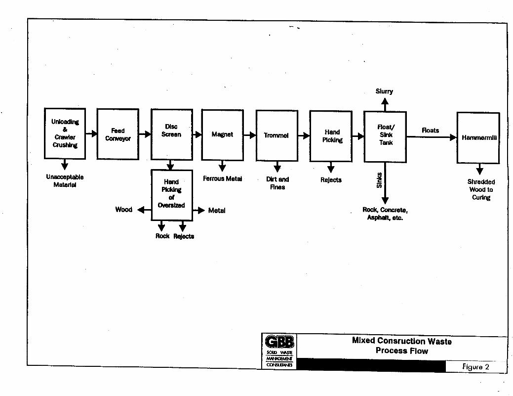
In considering mixed C&D waste processing systems as shown in Figure 2, several existing plants use mechanical separation devices (e.g., trommel screens and disc screens), in conjunction with air or wet processing separators. These dry or wet processes are, typically, applied for the separation of materials of organic or mineral nature. In the dry processing systems with air separators, a cyclone baghouse or bio-filter control system needs to be installed to properly treat and dispose of dust. In wet processes, the heavy fraction, rich in inorganics, sinks to the bottom of the wet quench tank, whereas the organic materials tend-to float and are removed in the wash water. When only water is the separation media, these units are commonly referred to as float-
' sinktanks.
6. Representative Facility Recommendations
Many technology systems and C&D processing devices have been introduced into the waste industry and reviewed by GBB staff based upon the type of material and quantity of C&D waste flows expected to be available. As a result of this review, several different system configurations have been deemed to be technically applicable and have the capability to be reasonably proficient in reducing C&D waste material going to local landfills, as well as providing products for local use.
Option I
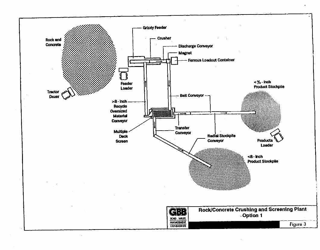
- Option 1 focuses on C&D waste materials that could be diverted from landfilling immediately by using processing equipment readily available from many vendors in the United States. The material selected for processing might be the inert portion of the C&D waste stream (consisting of concrete, rock, dirt, sand, etc.). This Option 1 concept allows for the production of an aggregate for fill at "clean fill" or reclamation sites and a dirt-like product. Ferrous metal would also be recovered.
The typical equipment needed for Option 1 (depicted schematically in Figure 3) are delineated as follows:
0
0
0
0
0
0
0
0
' 0 I
0
Tracked Front End Loader - Separates non-processible material and moves surge piles.
Front End Loader - Loads feederiscreen from nearby surge piles.
Feeder/Screen - Vibrating grizzly screen designed to pass sand, dirt, and small rock.
Crusher - Set to crush material 8 inches and larger.
Feed Conveyor - Moves oversized material from the feeder and the crusher to the screen.
Magnetic Separator - Removes reinforcing rod and other ferrous metal.
Double Deck Screen - Vibrating screen with two decks to produce three products: oversized (for recycling back to crusher), middling - an aggregate material, and fines - dirt-like material.
Recycle Conveyor - Moves oversized material from the screen to the crusher.
Middling Conveyor - A two-part belt conveyor (short fixed discharge conveyor and a stacking conveyor) for discharge of the aggregate fraction.
Fines Conveyor - A two-part belt conveyor (short fixed discharge conveyor and a stacking conveyor) for discharge of the undersize (fines) fraction.
0 Front End Loader - Loads products into trucks for removal and reuse.
Based upon the C&D waste to be processed this equipment has been specified to process up to a nominal 250 tons per hour. Technically, the system can be expected to operate on a two-shift basis, at an expected availability of 85 percent, taking into account both scheduled (preventive maintenance) and unscheduled (failure) outages.
- - Option2
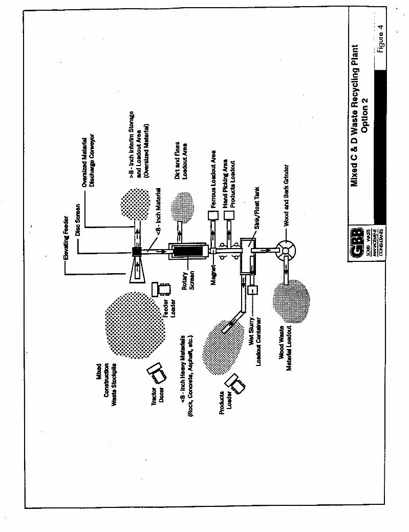
Option 2 is a Mixed C&D Waste Processing Option. This concept focuses on identifving mixed C&D waste makrial that can be diverted from landfilling. The raw material infeed would consist of: (a) certain building demolition waste; @) renovation waste; and (c) mixed site clearance waste materials. Generally, except for oversized materials that are screened initially, for economic viability, most of the products from this processing system should be useable to reduce the ultimate disposal costs of residue materials. The material products would be the inert portions of C&D waste, consisting of concrete, rock, dirt, sand, etc., processed to produce an aggregate and a dirt-like product. Additionally, ferrous and shredded wood products could be
generated.
Under this concept (depicted in Figure 4), trucks with loads of small-sized, inert material would be diverted by a spotter at the scalehouse for processing, along with mixed C&D waste loads noted above. Option 2 would not include a rocWconcrete crusher system;'therefore; only material that is less than 8 inches in diameter and falls through the disc Screen is processed further. Option 2, as depicted, would not address the processing of larger inerts, nor the processing of roadwork material and excavated material. The oversized product is assumed to be landfilled as a rejected material.
The typical equipment required for Option 2 is as follows:
Track Loader - Moves dumped material near to feed area; develops surge pile; and separates any large pieces of rock or concrete material.
0 Front End Loader - Loads feed conveyor and separates large inert material.
Disc Screen - Horizontal disc screen designed to eliminate material greater than 8-10 I inches in size. !
Magnetic Separator - Removes ferrous metal.
0 Trommel Screen - Set to screen dirt and fines - &-like material.
Handpicking Station - Sort out non-recoverable contaminant materials (e.g., plastic pipe) that might otherwise float and be carried over to the wood processing system.
Roadsink Tank - Designed to separate heavy inert fraction (e.g., rocks, concrete) from the lighter floatable fraction (e.g, wood). The heavy inert fraction would be available for use as fill at reclamation sites.
Hammermill - Shreds the float fraction - primarily wood. - .
For purposes of developing data for this paper, Option 2 equipment has been specified to process up to a nominal 150 tons per hour. Based on location and permit conditions, the system can also be operated on a two-shift basis, and has an expected availability of 85'percent for both scheduled (preventive maintenance) and unscheduled (failure) outages.
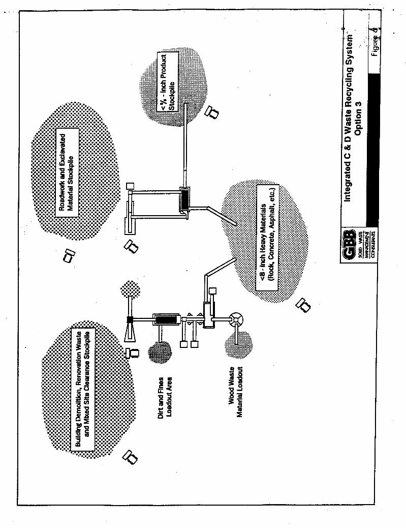
Option 3
Option 3 is the combination of Option 1 and Option 2, and is designed to handle most, if not
all, of the infeed waste categories presented within the overall C&D waste stream that are generally delivered to a landfill. This concept is designed to: (a) identify material that can be diverted from landf~lling by rockjconcrete crusher equipment that is readily available (e.g., excavated material, roadwork material, and certain building demolition waste); and (b) interface a mixed C&D waste processing system for the separation of the more organic-laden loads (e.g., renovation waste and mixed site clearance waste). Inherent in the design is the assumption that the recovered products are marketable.
To illustrate this combined system for purposes of this paper, this equipment is assumed to be specified td process up to a nominal 400 tons per hour. The material selected for the rocldconcrete crusher system is the inert portion of the C&D waste stream consisting of concrete, rock, dirt, sand, etc., as well as the oversized inert material separated from the mixed C&D waste stream. This would produce an aggregate and dirt-like product. Under Option 3, trucks with loads of inert material (or primarily inert material) would be diverted by a spotter at the RocWConcrete scalehouse for processing at the crusher plant, whereas organic loads would be sent to the mixed C&D waste processing system.
The concept for Option 3 is presented in Figure 5, and the equipment is graphically presented f in Figure 6.
Cost Estimatin g
GBB staff members have had discussions with several manufacturers for each representative type of plant discussed herein. Very preliminary capital costs, the costs of mobile equipment, exclusive of land costs, engineering, permitting and buildings (open air operations were assumed), are as follows:
Option I : RockKoncrete Crushing Plant Option 2: Mixed C&D Waste Option 3: Combined System
$ 1,800,000 - 2,200,000 $2,000,000 - 2,250,000 $4,000,000 - 4,500,000
Due to the extremely variable nature of local labor rates, fuel costs, fmance interest rates, recovered product values, etc., this paper will not attempt to present the annual operations costs for each technical option discussed. It should, however, be noted that, when conducting a life cycle cost modei, at a minimum the following seven major parameters should be covered: (1) annual C&D waste quantities; (2) recovered material quantities and unit sales prices; (3) product transportation costs; (4) operation costs (capital, operating, and maintenance); (5) projected tipping fee revenues; (6) disposal cost of nonrecyclables; and (7) landfa savings.
The economic models are sensitive to the prices received for reusable products. These parameters could be explored by sensitivity runs of the model to identify the full range of cost
or profit expected from the implementation of C&D waste recycling facilities.
A C&D waste recycling project is designed to tum waste products into reusable, marketable products. The operator must not only be mechanically proficient, but must have the appropriate marketing expertise to maintain a long-term, daily commodity movement at competitive prices to ensure a profitable business venture. The demonstrated capability of prospective vendors to: (1) efficiently and effectively operate the proposed technology; and (2) implement the marketing plan for the products generated should be of key to the public sector. A delicate equilibrium may ultimately be established between (a) the local landfill use and its associated costs and cash flows, and @) a local C&D waste recycling system throughput and its costs. Due to the separation and diversion of tipping fee revenues, this could be an economic issue to a local landfill if a publicaUy owned local contractor were running the public landfill and also happened to be the private C&D waste recycling operator. Depending upon waste stream mix, these two systems could, ultimately, be competitive processes, and must be evaluated carefully in a project feasibility study.

Segregated
Loads Concrete -P
Unloaded for
Inspection
Unacceptable Materlal
Grizzly Feeder
i Crusher t I
I I I I
Magnet
Undersized Material Ferrous Metal
Not to Scale
=D
I I
Multiple Deck
Screen
Product B
Product A
Representative Concrete Recycling Plant GIB Process Flow
v
Unacceptable Matertal
DISC Scnten Magnet
pkmz "- Of I krrwsMew
Slurry
4 I
Floats Float/ SWC PkWng Tank b Hemmermlll
Hand -b
Shredded wood to
ReJects
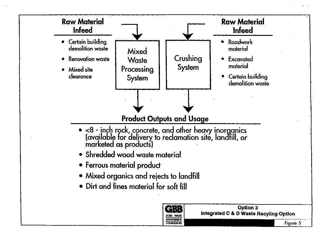
Raw Material Infeed
Certain building demolition waste
Renovation waste
Mixed site clearance
Mixed Waste
Processing System
Crushing System
1
Raw Material Infeed
Roadwork material
Excavated material
Certain building demolition waste
Product Outputs and Usage <8 - inch rock, concrete, and other heavy inor anics
marketed as products) 0 Shredded wood waste material
Ferrous material product Mixed organics and rejects to landfill Dirt and fines material for soft fill
(available for delivery to reclamation site, Ian 8 ill, or
c.
a i gif '