Embed Size (px)
Citation preview

TECHNICAL NOTE 2206
GRAPHICAL METHOD FOR OBTAINING FLOW FIELD IN
TWO-DIMENSIONAL SUPERSONIC STREAM
TO WHICH HEAT IS ADDED
By I.Irving Pinkel and John S. Serafini
Lewis Flight Propulsion LaboratoryCleveland, Ohio
Washington

s
.
NATIONAL ADVISORY COMMITTEE FOR AERONMJ!KKS
ZECHNICAL NWE 2206
GRAPHICAL MEIEOD ‘FOROBTAINING FLOW FIELD ti’TWO-DIMENSIONAL
SUPERSONIC STREAM TO WHICH HEAT IS ADDED..
By I. Ming Pinkel and John S. Serafini
SWY
A graphical method for obtaining the two-dheneional superso@cflow with moderate heat addition is presented. The basic equationswere derived for flows in which the total temperekure has a continuousveriation with displacement in the .?iirection,of the flow. For flowsat constant total temperatures before heat addition and with totaltemperature varying only in the direction.of the streamlines, simpll-“fied forms of the basic equations were obtained frm which workingoharts were plotted to facilitate construction of the flow. Theworking charts cover the range of Mach number from 1.3 to 5.0. Theapplication of the method and the charts are illustrated by a simpleexample, giving the flow around a mrved surface with addition of “heat in an adjacent finite layer where the initial total temperature
< of the flow is the same on all streamlinesafi lines oftotal temperature h the heated portionnormal to the streamlines. .
of the flow lieconsiantapproximately
INTRODUCTION
Current interest in supersonic flow includes flow thromh gasturbines and in ~et-6ngine &hausts in which heat release by–co%n-uing combustion of fuel introduced in an upstream combustion chambermodifies the flow. The general problem of the effect of heat additionon supersonic flows is of growing interest in the supersonic-flightand missile fields. The addition of heat to a gas flowimg in aconstant-areaduct with a steady supersonic veloclty has been investig-ated. (referenoe1). A theory for one-dimensionalsteady compressiblefluid flow in ducts with heat addition is presented.in’reference 2.An extension of the methcd of characteristics (for example, see refer-ence 3) for the graphical mnstmction of irrotational supersonicflows was develo~d at the NA!2ALewis laboratory and is presentedherein for obtaining the two-dimensional supersonic flow to whiohheat is added, The methti is restricted to flows in which the heattransfer between adjacent stream tubes can be neglected and entropychanges in the flow are due only to the additim of heat (shock-free flow)..
. .
—

2 WA TN 2206
The method of @aracteristics provides a construction of theirrotationalflow field subdivided into zones in each of which theMaoh nuniber,and therefore all properties of the flow, are constant.
r
When heat is added to the flow, further division of the flow isrequired to account for the variation of total temperature and total ~pressure throughout the field. Jn the rotational flow that resultsfrcm the addition of heat, compressionand expansion waves arise in
r
the flow to maintain continuity of statio pressure across adjacentstreamlines. Because of the changes in total pressure and tempera-ture and the generation of waves within, the flow streamlines andheat-additionmeference lines must be plotted with the waves. Thecanplexity of the graphical oonstzwction of the flow that resultsfrmu heat addition and wave generation can be reduced by methcxlspresented herein.
The equations developed as the basfs of the proposed methd ap-ply to any mode of heat addition that gives a continuous variation oftotal temperature with displacement in the direction of the flow (butnot necessarily continuous variation normsl to the streamlines). Forflows at constant total temperaturebefore heat addition and withconstant total temperature along lines approximatelynormal to thestresmllnes, stiplified forms of the basic equations are obtainedfiomwhfch working charts have been plotted to facilitate the con-
.
struction of the flow.
As an Illustrativeexample,v
application of the proposed methodis made to the problem of obtaining the heated supersonic-flowfieldad~acent to a curved wall. The initial total-temperatureof the flowis the same on all streamlinesand lines of constant total tempera-ture in the heated portion of the flow Me approximately normal tothe streamlines.
SYMBOLS
The following symbols are used in this report:
CPspecific heat at constant pressure, herein assumed to beconstant
Cv specific heat at constant volume
M Mach number
N square of I&ch number

IWCA TN 2206 3D
P
Aa
total pressure
static pressure
heat content of flaw based on total temperature, Q . CPT
gas oonstant
total temperature
static temperature
velocity
mgle through which supersonic stream is turned to acceleratefrom M =1 to M>l
wave strength expressed in terms of deflection produced insupersonic stream (positive mlue of Ac% is that whichincreases static pressure)
W.ch angle, sin-l l/M .
ratio of specific heats, ~/~
angle hetween looal velocity and direction of initial flow
density
Subscripts:
o refers to initial conditions before
1,2,3,... des~te particular sector of flowwaves, by heat-addition lines, or
METHOD
Basic considerations
For the purposes of the method presented,
addition of heat
field bounded %yby both
the addition of heatto the flow in a stream tube is considered a ho-step process. Thestream tube is divided into short intervals along its length, over
% each of which a small change in heat content of the flow occurs. Allthe heat addition in each interval is considered to take place along

4 NACA 3!N2206
n
a lfne at the middle of the interval. The heat addition is asmmedto take place at oonstant stream-tube area. Following the heat addi-tion, the streamlines ohange direction, with a corresponding change
?
in stream-tube area to adjust the local statio pressure as required 5by the adjacent flow. 3
Governing Equations
1 The change in statio pressure with a heat addition AQ at con-stant stream-tube area is obtained by application of the oonservation-of-mcmentum and the continuity equations. For the constant-area ease,these equations have the form
EI+PV2=K1
fmzrK2
where K1 and K2 are constants. Eraperfect gases,
P=&
and the equation for Mach rnmi%er,
.
(1)
(2)
the equation of state for
..
u
equations (1) and (2!)beoome, respective,’
p(l+yl?)=Kl ~ (3)
d!!=K22Rt
(4)
where N . #. Differentiation of equations (3) and (4), wrztten inthe approximate-differenceform, and substitution of
( )T=tl+~N yield, on the elimination of A@ and AP/P,
successively,
(5)

NACA 22?2206
a
5
(6)
where
C=W (7a)
D=.Yz2!&M”N-1
(“n)
Q = CPT (7C)
(7d)
Adjustment of the pressure following heat addition, as required.bythe ad~acent flow, Is accar@ished by a wave of strength Am gen-.crated in the flow at the point of adjustment shown in figure 1.If Ap is the required pressure change across the wave, the value
“% is given by the simplified relation suitable for waves of mallstrength,
(8)
where
“A=~T
(8a)N-1
and a positive value of Au is that which produces an increase bstatio pressure. The sum of static-pressure changes resulting fiauheat addition at constant area, folluwed by pressure adjustment, isobtained from equations (5) ami (8):
(9)

6 NACA TN 2206
a
The ~ch number changeobtained by differentiating
in the flow orosshg the wave may bethe wel.1-lmownPratitl-Meyer expression v ,
to obtain the expression for a small finite change in CL
.~a=md!E_.-2N1++
or
AN—a-N Aa
(Ma)
(lOb)
The total change in AH for the heat addition at constant area andsubsequent pressure ad@stment is obtained from equations (6) and(lOb) as
Application of Governing Equations
Equations are now developed for four distinct cases of flowad~us-ent that arise In the solution of heated supersonic flows bythe method of this report. To each case of flow adjustment corre-sponds a generated wave pattern that can be computed by applicationof equations (5) to (lob). Because the method of solution appliesto any mode of heat addition that provides a continuous variation oftemperature along a streamline, the heat content per unit mass offluid Q may vary discontinuouslywith displacement across stream-lines. For the special case in which the total temperature is con-stant on all streamlines upstream of the heat-addition region andlines of constant total temperature lie normal to the streamlines inthe heat-addition zone, simplified expressions suitable for computingworking charts are obtiined for the waves generated.in the four casesof flow adjustment.
.
v

NACA TN 2208 7. .
The marked effect of small quantities of heat added to thes flow, representing a change of several percent in total tempera- “
ture or heat content Q, onthe local properties of the flowP requties that heat-addition reference lines be drawn in the flowWc) to devide the flow into zones in which a change in heat content Q4 .of only 2 or 3 percent occurs. These reference lines, drawn normal
to the local streamlines for convenience, represent the intervaloenter lines discussed in the previous section, at which all theheat added in the interval is concentrated.
Case I: wave generation at boundary between heated and unheated.
flow. - The first case considered is schematically illustrated infigure 1, which shows the flow adjustment that occurs along a stream-line separating heated and unheated portions of the flow. The pres-sure equilibrium that exists across the bounding streamline beforeheat addition is restored after heat addition by a deflection of theflow acccqanied by the generation of two waves of equal magnitudebut opposite sign. Subscripts used in the following derivationsrefer to flow regions numbered in the figure. From equation (5),the pressure p3 in the heated stream tube, after a head additionof AQ, iS
-
p-.)]yNl+~N (AQ)2P3 =P~+P2 N-1 Q2
2
(1.la)
where (AQ)2 and Q2 m?e associated with the flow in region 2. IfAcLl is the turn in the bounding streamline required to restore pres-sure equilibrium in the regions 4 ami 5, then fran equation (8),
(llb)
(nc)
If A% is the wave strength associated with the flow having the
% value of 1?. I?l,then the wave sepe&ating regions 3 and 4 has the
strength -Aal. With the condition that the static pressures on
“=

.
8 NACA TN 22Q6
%
both sides of the boumifrigstreamline are equal after a heat addition —of (AQ)2, P4= P5,
equation (llb), the
and ‘tiththe substitut~on of equation (ha) in R
folluwing expression is obtained: ‘G- - 2
With the substitution in equation (lld) of N3 in terms of N2by ~ns of equation (6), and frcmthe relation P1 ‘=~~ the solution
of the equation (lld).for Aal in terms of known iuant~ties is
. .
(12i
‘“1=*
where A, C, ati D are defined by equatiom (6a), (7a), d (7b),respectively, ad”
F =N+D$$ (12a)
The expression for AcLl (equation (12)) can be written as a function
of NIflTz afi N2 that is convenient for presentation in chart form.
The chart and its uses are presented when the complete graphicalmethd is considered.
me Pressure -we P4-P2 iS obta~d bym~ns ~ eq.wt~oIM (11~)am3 (12) as
●
..
r
.
.
*’.
%
—
2 NACA TN 2206 9
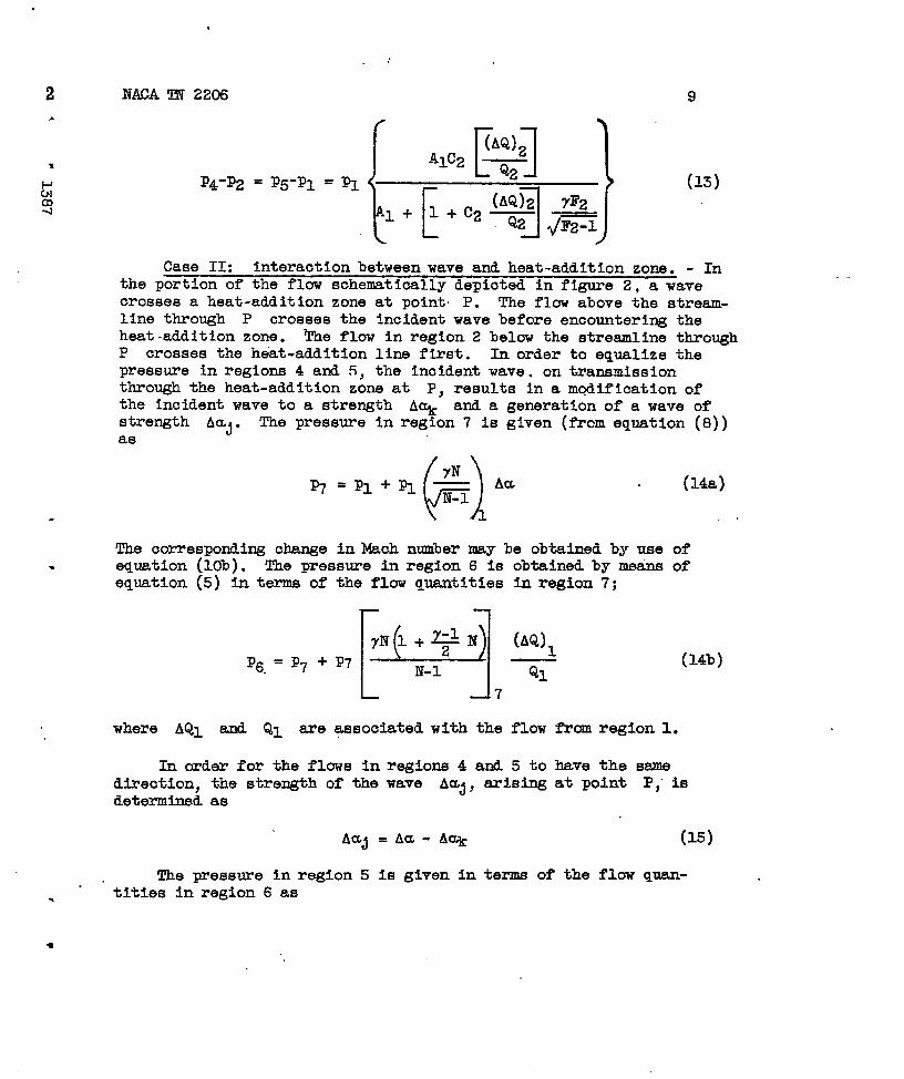
Case 11: interactionbetween wave and heat-addition zone. - Inthe portion of the flow schematically depioted in figure 2, a wavecrosses a heat-addition zone at point P. The flow above the stream-line through P crosses the incident wave before encountering theheat-addition zone. !t’heflow in region 2 below the streamline throughP crosses the heat.addition line first. In order to equalize thepressure in regions 4 and 5, the incident wave, on transmissionthrough the heat-addition zone at P, results in a mc?dificationofthe incidentwave to a strength A% and a generation of a wave ofstrength Auj. The pressure in region 7 is given (from equation (8))as
.
(14a)
The corresponding change in Mach number may be obtained by ue of. equation (lob). The pressure i.nregion 6 is obtained by meanE of
equation (5) in terms of the flow qua.ntltiesin region 7;
P6 =p7+p7 [1EE21)!!iN-1QI7
(14b)
where AQ1 and Q~ are associated with the flow from regionl.
In order for the flows in regions 4 and 5 to have the samedirection, the strength of the wave AUj, =iS~ at point ~; iSdetermined as
Aa~ =Aa- Aak (15)
The pressure in region 5 is given in terms of the flow quan-.’tities in region 6 as
●
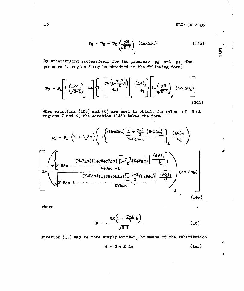
10 NACA TN 2206
.
()~ (Aa-A~)‘5=p6+p6-
6
(140) r
z“mA
By substftuti~ successivelyfor the pressure p6 and p7, the
pressure in region 5 may be obtained in the following form:
When equations (lOb) and (6) -e used to obtain the values of N atregio~- 7 and 6; the equation (14d) takes the form
[
1+
(AQ1QI. )
(,[ [ 1
(AQ)l(N+BAa)(l+~N+yBAa)l+~(lV+BAa) Q1
y N+BAa -N+BAu -1
c
‘)
] (Aj~(N+BAa)(l+yN+yBAa)@#N+BAa)
N+BA*l -N+BAa - 1
1- 1
(14e)
where
Equation (16) may be more simply wrttten, by means of the substitution
lE. N+B Aa (14f)
.
w

.
*
NACA TN 2206
.- 7
P. = Pl (1 + ~Aa)
-r
h a similar manner, the pressure
)(Aa-Ac@
IL
.
L )1(AQ)l -
++E ~yE - E-1
I (E(1+7E) 1+ ~
-dE-1 -E-1
(14g)
in region 4 may be obtained as
where C and F are fnnotions of N as defined in equations (7a)and (12a), respectively. With theuse of P1 = p2 and p5 . p4,
equations (14g) and (14h) may be solved for A% as a function of
the lmown quantities Rb N2$ (AW./QI., (A02/Q2, am AU:
(AQ)2Z1-l +YIZ1 Au - C2 —
QzA% =
Ylzl +W2(17a)

NACA TN 2206
“
12
where — —
,&l+Y.)(;:h)%#j
Y1 =
rl-
7-1
)(
AQ I+--p *
, E-1 -LV
( {)Zl=l+AIA~ +
E-1 _ll
.2=fp.q(&’_’2}2
(18)
,
Where the hit ial total temperature is constant and the heat addi-tion is considered ponstant along lines no?mal to the local stream-lines, Ql . Q2 = Q h (AQ)l = (AQ)2 = AQ. ~erefore, with
N1 = IY2. N, equation (17a) fs written in terms
Aa as
Z-1 +YZ Aa- cA&
A% =Yz+w
of N, AQ/Q, ~
(17b)
where Y, Z, and W are evaluated as givenby equations (18), withQI = Qz = Q, (AQ)l = (AQ)z = AQ, and NI = N2 = I?. The pressurechange may be written as
r 1(AQ)221-1 + Y1!Z1Au- ~z —
P5-P1 P4-P1 =C2 (AQ)ZJ Qz—.PI = PI
—+W2Q2 Ylzl +W2
,(19) .
.L -1
9

IWICA!iN2206
.
13
Case 111: wave propagation across adjaoent stream tubes ofs differing total pressure. - A wave passing through adjacent stream
tubes of differing total pre#sure prcduoes unequal ohanges of staticLb pressure in the stream tuhek. h order to maintain continuity of9 static pressure and flow direction downstream of the wave, the wave
is modified in strength and another wave is generated at the stream-lines separating two adjacent stream tubes of differing total pres-sure. The situation schematically illustrated in figure 3 is con-sidered: A wave of strength Aa is shown crossing the boundarybetween regions 1 and 2 in which the flow is parallel and at the samestatic pressure upstr&am of the wave, but differs in Mach number. EA% fs the strength of the wave transmittetithrough the boundingstreamline ami A* the strength of the wave generatedat the lounding
tireamline, then
(20a)
The generatedgiven by
P3 =()
p2+p2m Aam2
(20b)
.
wave A% will produce a change of pressure that is
(i-)l?4=P3+P3~E-l
3
h order for the flow in adjacent streamdirection,
The requirementvides, by means
.
s
A+ (Zoc)
tubes to have the sane
(21)
that the pressures in regions 4 and 5 be equal pro-of equations (lob), (20), and (21),
-—-

14 NACA TN 2206
Inasmuch as pl . p2, solving for Acq#Au gives
(23a)
Where the strength of the incident wave Au oanbe assumed to besmall (lAal s1.000), calculationshave shown that the pressure andthe Mach number changes from region 2 to region 4 can be consideredto result from a combined wave of strength Am+ A% acting on theflow in region 2. Equation (23ct)then is of the simpler form
A2
(23b] .
r
Case IV: heat addition across &idJacent stream tubes of dif-feri~ total pressure; - The difference in the change in statio pres-sure produced by additions-of heat to adjacent stream tubes ofdiffe~ing total-pressure is compensated by waves of equal intensityand opposite sign generated at the streamline separating the twostream tubes, as illustrated in figure 4. ~ (AQWQI ~
.—
(AQ)2/Q2 are the values associated with the flow mom the regions 1
and 2, respectively, the pressure in the regions 6 and 3 are obtainedfrom equation (5) as
— -
LL)yNl++N (AQ)I ,p6=pl+pl N-1 QI
(24a)
1
P3 [1=P, +p2 ‘Nf++N) @Q)2 ‘N-1 Q22
(24b)

2206 15
is the wave asscoiated with the flow having the Value of
then the wave separating regions 3 and 4 has the strength-Aa~. The pressures in the
G2 quantities in the regions 6
regions 5 and 4 in terms of the flow
and 3, respeo!tively,are
= Aal()‘5=P6+PW=6
()P4=P3-P3—&3A~
(24c)
(24d)
Because p5 =P4, the ~ubstftutfonof equations (24a) and (24b) inequations (24c) and (24d), respectively, yields
(25)
where C and. F are functions of N prwiously defined (equa-tions (?a) and (L%), respectively). Because PI =~, ~uatio~ (25)$solved for Au1, yields
If the initial total temperature is constant and the heat additionis constant along lines normal to the local streamlines,(AQ)l = (AQ)z = AQ afi QI = Q2 = Q. men e~uation (Zea) becomes
.
8

NACA TN 2206
Working ChartB. - By means of equations (5), (6), (12), (17b),(23b), and (26b), and with y =-1.4, charts were obtained to facili-tate the graph&al construction of heated supersonic ?1OWS where theinitial total temperature is the same on all streamlines and thelines of constant total temperature In the heated portion of the fl-&are normal to the local.streamlines. These conditions are approxi-mated in ducts and channels having am initially uniform supersonicflow inwhioh heat release by chemical reaction is occurring in thebody of the flow. ‘
The exact differential form of equation (6), giving the changein N with a heat addition of AQ/Q at constant area, has beenintegratedand the results are given in figure 5 for AQ/Q of 0.02and 0.03 with AN = N1-N2 as the ordinate and N1 as the abscissa.The static~pressurechange and the total-pressureratio across a heataddition have been calculated by integrating the exact differentialform of equation (5) and using the values of N2 obtained fromfigure 5 for a given ‘AQ/Q. The variation of the static-pressurechange and thetotal-pressure ratio across a heat-addition zone withNl, the value of N preceding heat addition are given in figures 6and 7, respectively.
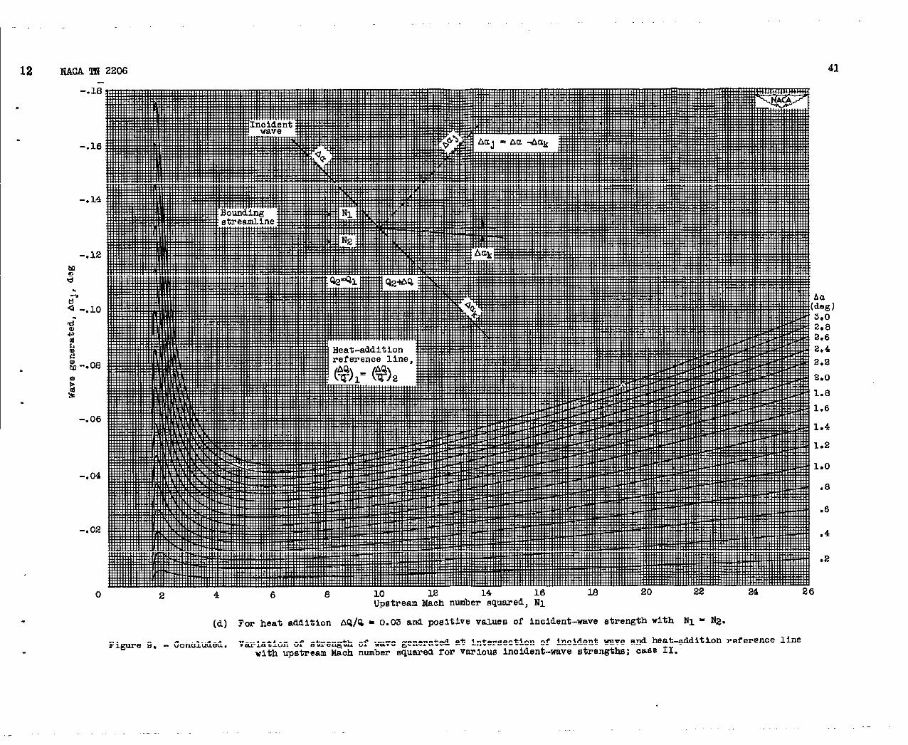
The value of Aal of case I as a function of N2, with N1/N2as a parameter, is presented in figures 8(a) an3 8(b) by means ofequation (12) for AQ/Q of 0.02 and 0.03, respectively. The value’of Aa~ in case 11 as a function of N1 with various values of AmIs presented in figure 9 by means of equation (17b) for AQ/Q of0.02 and 0.03 for both expansion and compressionwaves. me ratiosA~/Aa and A~/Acz of case III are calculated from equation (23b)and presented in figure 10 as functions ‘of A /A2.
~(Equation (23b),
which is an approximate form of equation (23a , gives sufficientaccuracy In the range N . 1.5 to N = 25.0 for small values of As.)For ]Aal ~ 1.00o,“theuse of the chart of figure 10 gives values ofthe modified and generated waves, which @ve less than 0.5-Tercentdeviation frcm the values bbtained from the more exact equation (23a).●
The variation of A (equation (8a)) with 1? is shown infigure 11. The value of Aal of caOe IV, calculated from equa-
tion (26b), is presented in figures 12(a) to (12d) as a function of .
.
w
,
I-,
z I2 i
–8
-i
.-
—
.
*.-
----
.,
.

3.
.
d
NAC!ATN .2206 17
HI with various values of N2. Figures 12(a) ati 12(b) give thevalues for Au~ of ease IV with AQ/Q = 0.02, and figures U(c)
and 12(d) give the values for Aal of ease IVwith AQ/Q = 0.03.For a given AQ/Q, the curve of Aa~ against N1 is coincident
for N2 = 3.o and N2 = 4.0 and very similar for 3.0 CN2<4.O.Figures 13 and 14 shuu plots of N against a, the Prandtl-Meyerturning angle, and N against ~, the I&oh angle, respectively,with expanded soales that are convenient for graphioal plotting.
COMPUTEGRAFEICALMETEOD
The initial layout of the graphioal oonetruotion for heatedsupersonic flows begins as for an irrotational supersonic flow.Curve&walls bounding the flow are approximated by ohord lines ofsmall angles of inclination relative to adjacent ohord lines. Ifthe initial upstream flow is rotational, the flow is divided intostream tubes in eaoh of which the Mach number is oonsid&ed to havethe value,on the streamline through the middle of the stream tube.The plot of the flow proceeds by successive application of the fourcases for whioh equations were developed in the preceding section ofthe report. It is as-d that in any problem the variation in totaltemperature thrmzgh the heated portion of the flow is sufficiently wellknown for the accuracy desired in the construction of the flow. As theflow conetmzction proceeds, heat-addition reference lines are drawnnormal to the loosl streamlines. For flows inwhioh the lines of mn-stati total temperature also lie normal to the stresmiiines,the heat-addition referenoe lines are also lines of constant total temperature.In the interval between oonseoutive referenoe lines, the fractionalheat additionto the flow AQ/Q shouldbe equal to or less than 0.03for values of N froml.5 to 16.0 in order for the equations repre-senting the effect of heat addition on the flow to apply with satis-factory aoouracy. For values of N greater than 16.0, sm!dler valuesof A~Q are to be used, (for example, for N of 25.0, a satisfactoryvalue for AQ/Q is 0.02). When the total temperature is not constantalong referenoe lines, the flow is divided into stream tubes, in eachof which the total temperature is assumed constant and equal.to theaverage of the values at the bounding streamlines. A sufficient numberof stream tubes are ohosen to approximate the variation of total tem-perature normal to the streamlines.
The application of the flow-oonetructionmethod considered isessentially the same for flows in which the total temperature isoonstant or varies along lines normal to the streamlines. h order

18 NACA TN 2206
to illustrate the application of the working charts, an example isgiven in which the total temperature is constant on lines normal to ,the streamlines.
sThis example, shown in figure 15, presents the oontruction of :
a heated supersonic flow adjaoent to a curved wall. The flow,initially uniformat MO = 4.0, is bounded by a single wall curvedthrough 40 on a circwlar arc between points A and B and theunheated flow extending to infinity. The streamlinebounding theheated portion of the flow goes through points E and F. A quan-tity of heat AQ/Q = 0.03 is added at regularly spaced intervalscorrespondingto 10 turn of the bounding wall. In any interval n,
Q =QO(l+AQ/Q)n, where @ is the value of Q before heat addi-tion. Waves arising or reflected from curved walls bounding the floware handled in the manner employed in two dimensional irrotationalflows.
The cumeU wall is approximatedby chord lines of increasinginclinationto the initial flow direction in increments of 1°. Thefirst wave is generated at the wall at point C with the strengthAa = -1:OO. The correspondingMach nmber change and hhch angle Pimposed on the flow by the wave are obtained from fi’gures13 and 14, .respectively,which give, for NI.= 16.0 and Aa = -1.Oo, N2 = 16.62
~ P = 14.48°. The value of N and the inclinationof the flow tothe initial flow direction are recorded in figure 15 as N/e, which *in this aase is 16.62/-1.000°. Negative values of e indicate aclockwise turn of the flow where the initial direction of the flow isfrom left to right. At the intersectionof the wave and the firstheat-additionreference line at D (fig. 15), the situation classifiedas case II occurs. The generated and transmittedwaves axe obtahedfrom figure 9(c) and equation (15). With Aa= -1.OOO, NI = 16.00,
and AQ/Q= 0.03, Aaj is equal to 0.034° ami Aak = -1.034°. The
change in the value of I? across the heat-additionreference lineis obtained from figure 5, with subscripts 1 and 2 representing theupstream and downstream flow, respectively. me c-e in the valueof N dcross each wave is obtained from figure 13. The values forN and 8 are shown in the appropriate sections of the flow (fig. 15)and Aa~ and Au& are recorded on the correspondingwaves. me
streamline through point D (fig. 15) is turned through an angle A~.
The flows above and below this streamline have different total pres-sures and the streamline DH is drawn in the plot of the flow todemark this difference.
.
9

NACA TN 2206 19,-
.
g4
Along the streamline bounding the heated W unheated flow, twowaves of equal magnitude but opposite sign are generated at thepoint of intersection E (fig. 15), with a heat-addition referenceline corresponding to the situation classified as case I. The valueof ACLI is obtained frcm figure 8(b) for N1/R2 = 16/16 = 1.oo, as
Aul = 0.899. The change in N of the unheated flow is obtainedficm ffgnre 13 for N = 16 and Au = Aal = 0.899. The change in Nof the heated flow across the heat-addition zone is obtained frcmfigure5 for N1.16 and AQ/Q =0.03, as N= I-3.33,and acrossthe wave Aa= -A% = -0.899 from figure 13 for IVl= 13.33 and
Aa = -0.899 as R = 13.78. The flow zones involved are labeled withthe appropriate values of N @ e and the strength of the wavesare indicated as well. It should be observed that a positive (com-pression) wave extending from the-upper left to the lower right willproduce a clockwise turning of the flow, as does a negative (expan-sion) wave extending from the lower left to the upper right (forexample, point D). Likewise, a counterclockwiseturn of the fluw isproduced by both a positive wave extending from the lower left tothe upper right and a negative wave frcm the”upper left to the lowerright (for example, petit E).
At point F in figure 15, a wave is incident on a streamlineseparating regions of differing,total pressure, which corresponds tocase III. An enlarged figure of the zone in the neighborhood ofpoint F is shown in figure 16(a). The I?e~U&ed VdUt3S Of Al 8nd
A2 m obtained frcxzfigure 11 for I?l. 14.55 and N2 = 10.59,giving AI = 5.534, A2 = 4.788, and A~A2 = 1.156. By us- fig-
ure 10, the corresponding values of the transmitted and reflectedwaves Aqt and Aar (fig. 3) may be obtained as -0.988° and-0.0770, respectively, for Am = -1.0650. The change In N acrossthe various waves is obtained I&cm figure 13 for the correspondinginitial values of l?. The Mach angle between the streamline andthe waves is obtained &cm f@ure 14 as the ~le p. It should benoted that whenever AI and A2 are very nearly equal, the value
of A% is so small that it canbe assumed to be negligible and
A% is then equal to Aa (f@. 10).
Waves generated by the addition of heat to ad$acent flows ofdifferent total pressure, considered as case IV (fig. 4), are shownin figure 15 at point Gad are illustrated in detail in figure 16(b).The s-engths of the generated waves, which are equal in magnitudebut opposite in sign, are obtained frc& figure I-2,depending on thevalue of AQ/Q and N2. For the case cited, NI = 10.52, N2 = 10.39,

20
AQ/Q = 0.03Xand AUI is evaluated as .-0.0050.value of A% is very small unless N1 and N2
ably. The change in the value of N across the
NACA TN 2206.
In general, thediffer appreci- .
heat-addition zone*a
a~-the waves ~e obtained eucces8ivelyfrom figures 5 and 13 fcm 3the appropriate local values of N, ati the correspondingvalues of~ are obtained from figure 14.
An enlargement of the region near point H in figure 15, inwhich the combination of cases II and IV occurs, is presented infigure 16(c). The wave Am . -0.966 crosses the heat-addition refe-rence line at point H, as does the streamline that separates tworegions of differing total pressure. From the graphical solution ofcase II, the values of the trapmuitted and the generated waves areAak = -0.995 and Aa~ = 0.029, respectively. For case IV, the values
of the generated waves are ‘%pper = -0.002 and A~ower = 0.002.
Therefore, the values of the transmitted ami the generated waves ofcase 11 and ca~e IV are s-d algebraicallyand plotted as -0.997and 0.031, respectively,as shown in f@ure 16(c).
It is evident that the number of waves and streamlines sepa-ratt~ regiom h the flow increases as the plot of the fluw develops. ~When It becomes desirable to limit the number of waves and stream-lines that must be plotted, several devices may be used for combiningwaves and reducing the number of streamlines separating flows of dif-fering total pressure.
~A typical example of the reduction in the
number of waves by combination of a weak and an adjacent strong waveis shown in the region about I in figure 15, wherein weak waves aredesignated by short dashed lines. Figure 17(a) presents an enlarge-ment of”the portion of $Ygure 15 near point I. The wave Aa . ().030°is combined with the wave Aa = -0.9250 by using algebraic additionof the wave strengths to give a resulting wave of strength Au = -0.8950.This device is generally employed at the heat-addition reference linebecause every wave that crosses a heat-addition line generates an addi-tional wave of minor strength. Figure 17(b), which gives unenlargedview of figure 15 near point J, depicts a similar situation where theincoming minor wave Au = 0.0340 is mmbi,ned with the wave Au = kl.000arising at the wall boundary. The wave that is drawn downstream frompoint J at the wall b-y is equal to -.09660,which represents thealgebraic sum of both wave strengths. This method of combining wavesavoids the accumulated error that would result fl?cxnneglecting theminor waves and introduces only minor local errors in the flow.
A method for reducing the number of streamlines separating regionsof differingtotal pressures is presented in figures 17(c) and 17(d), “
.\

NACA TN 2208 21.
.
Gc14
which show an enlarged portion of figure 15 near point K. In fig-ure 17(c), the streamlines E and F, if drawn past waves U and V,would separate regions of different total pressures but of the samestatic pressure. A single streamline Hreplaces EandF (fig. 17(d)).The streamline H is positioned according to the equation
(1’?2-Nl)d= (N3-N2)e (27)
The flow zone N2 is eltited. This procedure my somewhat dis-tort the rotational properties of the flow; also, when the differencesin IV become large, the accuracy of the resulting plot may be hnpaired.
If the number of stron&waves that arise at the fixed or free-stream boundaries becomes very great, the method illustrated in fig-ure 18 can be used at the expense of accuracy in the plot of the flowto reduce the plotting w~k. Along a line -ediately upstream ofa heat-addition zone, a break is made in the plot of the flow. hthe space provided by the break, a simplified form of the flow is sub-stituted for the upstream flaw. In figure 18 the letters A, B, C, Ddesignate waves-immediately upstream of a heat-addition zone. Ineach region of constant total pressure, such as that enclosed by
. streamlines R and S, waves of the same family as A and C are combinedby adding their strengths. The combined wave is located at theweighted mean distance between wave A and C, &. Cc, whenA~C
i are taken to represent the absolute magnitude of the strengths of thecorrespondingwaves.
The
from the
where P
static pressure at any point in-the flow”field may be obtainedrelation
#=tl+*@
and N are the 10cA values of the total pressure and theMach number squared, respectively. The local value of N appearson the graphical plot. Because the total pressure changes with heataddition in a manner that depends on the variation of N along eachstreamline, the local value of the total pressure must be obtained bytracing the changes in the total pressure along the particular stream-line passing through the given point. ~ order to obtain the changein the total pressure across each heat amitfon of AQ/Q, fi~e 7or the “relation

22 NACA IN 2206
L -
may be used, where the subscripts 1 and 2 refer to the regionsupstream and downstream of a heat-addition referenoe line on thegraphical plot of the flow field.
Lewis Flight Propulsion Laboratory,National Advi.ac&yCommittee for Aeronautlca,
Cleveland, Ohio, I&y 31, 1950.
lmFERENcE9
1. Foa, Joseph V., and Rudhger, George: On the addition of Heatto a Gas Flowlng in a Pipe at Supersonic Speed. Rep. No.HF-534-A-2, Cornell Aero. Lab.. Ino., Feb. 15, 1949. (ONF!Contract N60ri-11911.)
2. Hicks, Bruce L., Montgmery,
The One-Dimensional’Theoryin Ducts with Friction and
3. Sauer, Robert: IntroductionJ. W. E3wards (Ann Arbor),
. .
Donald J., and Wasserman, Robert H.:
of Steady Compressible Fluid FlowHeat Addition. NA!XTN 1336, 1947.
to l!heorethal Gas Dynardcs.1947.
.
.

1
1387, , 1 I
Bauiilng
./ kmerated wa7e,
/
ha = Aal
/
Unbea&d flcu
/
(luayyayylly\,
\
Heate~ flow
IHeat-atiititonreferenae line \ Qen9rahM wave,
Aa . -A%
Figure 1. - Schw&lc repre~entattonof wave generation atibmmlary
between unheatedaml heated flou; osse 1.

Eeat-addltlon
referenoe .lha
\Jnoldent wave,
Aa
\
\
Flow direotlon~
\7
1
\P+
/ Strwmline through lnteraectlon2
of wave and
..’
heat-addition line
/
. ~Generated wave,
/’ Aal . Aa - A%
-b /
/’/-
6//- ~ Origlmbl streamllna
/5 f ~ db?eotlon------ ----- ------ -- -
\&lk
\
~?-Defleoted streamline
3
I \‘\
\ Tranamlttal wave,/-
\AaIS
v“
heat-widltIon referenoeliqe; ease II. ~~
!3
Figure 2. - Sohemtlo representation of!wave propgatlon aoroes
, . ,L8’ZT
1,s
1, 11, ,,1
.

( 1 A, .
.
L !h’anmdtted wave,
/
A%
/
Nl/
Flow dtreotion~~“
BoW- /5 BounAing streamline
1slmeamltne A%
2/
\ ~––– – – – ‘~–&T@hl streamline
Hz ~\ direotion
‘/
~\—————\
\
/
\
/
~Inoident wave,
Aa
F@ure 3. - Schematic representation of wave propaga~lontubes of differing total pressure; ease
‘\
wave,
‘=s=-acrosa adjacent btream
III.

Heat-addition
reference line
N1
Flow direction ~1
Boumi@ streamline Jr?~ 2
>
F Generated wave,
/
Aa = Acq
/’5——streamline
Aa———— —-——
\4 ‘—xGTginal streamline
3\ direction
\fGenerated wave,
\
Aa = -Aa~
Figure 4. - Schentatlc representation of wa~e generation at intemeotion of heat-addition
referenoe line with adjacent stream tubes of differing total pressure; Oaae IP.
.
, . 1
,,
I

6.0
5.6
6.0
4.6
4.C
o e 4 6 BL&mm I& number i$ured, MY
lE 20 ‘.%2 al 26
Fi@me 5. - VWlmtlotI or oinngc of Ikh numbar Bqwed mrom hat tiitlon with uptreti Maoh nticr nqwe.1..

I
.30
.25
.!20
.16
.10
.06,,0 2.4 6 8 10 12 14 16 la 20 E? 24 26
Uptreem )w.ohnumber awared. RI
II
to upstiem at8tie pewure with wtrea9 Ilmh nmbarE
s!
NMom
,f
1 I ,,,

,
-.
m
l.a
.95
.W
.70
.60
.eu0 e 4 6 e 10 la 14 18 la 20 z? a4 ao
Upwrwa Ha&l nlmbm aqumed, li~
Flgmw 7. - VsriatlOn of ratio of total pemurc Lwfc.rehemt addition to tit titer haat dditlon with uimtrmm Mmh umber ml-d.
,, ,,. . . ‘,
E’s
coa

.
#I
I ,

7
.NACA TN 2206
..9C
.76
.’70
.66
.64
.55
.W
.46
.4(
Ilnah number squured upstream of heat addition, w
(a) For heat addition, (A@).2 = 0.c12.
Figure .9, . Variation or strength of vave generatwl at free-stream boundary of heated flow (from equation (12)) With I&oh
number sqwed upstreem of heat addition; fxwe I.

,L
.

8 IWA m 2206
1
.
1
.
..
L
33
1.1
1.0
.44
.6E
.M1
.6E
.76
Uaoh number aqufuwd upstream of heat mddition, N2-.
(b) Por htiat addition, (AQ/Q)2 - O.CS.
$’Iguro 8. . Conoltied. Variation of eirrength of wave generated at rren-atrenm bourdarg of heated flow (from equation (IJ?))
with naah number squared upatmaw of hamt tilt ion; onae 1.
.

, f , ,
.-
1
.-
.
-—

9 NACA ‘El2206
.18.
.16
.14
.1.6
.
.06
●O4
.02
0
.
.
35
2 4
(a) For
Figure 9. - Vml.atlon of
(*g)-s.0
-2.8
-2.6
-2.4
-2.2
-2*O
-1.8
-1.0
-1.4
-1.2
-1.0
-.B
-. 6
-.4
-.2
6 e 10 u?. M 16 M 20 22 24Upstream Maoh number mmred, N1
26
heat addjtion AQ/Q = 0.02 and negative values of inoident-wave strength with N1 * N2.
strength of wave generated at interseotlon of inoldent wave and heat-addition reference llne with upstreamMaoh number squared for variOUs inoldent-wave strengths; ,oase II.

.
.,.
I
. ..
.
,.
I

I,,
.1(J NACA TN 2206 37
2.0
2.2
1.8
1.4
1.0
.8
Upstream Maoh number wluaredj NI
.(b) For heat addition AQIQ = 0.02 and positive values of inoident-wave strength with NL R N2.
.Figure 9. - Continued. Variation of strength of wave
with upstieam Maoh numbe~generated at interaeotion of inoident wave and heat-addition referenoe linesquared for various Inoident-wave atrengtha; oasQ II.

1’
.
.
I
.,,,
I ,,
.
,,, ~:,”: I
,’
1
t
I
I,’ i

I
.11
.
MAOA ‘IN 220639
●4
.2
.0
.8
.6
,. 4
,. 0
-. 0
-.6
-.4
-.2
0 2 4 6 8 10 12 14 16 M 20 22 24
Upstream MCiI number aquered, N1~26
(c) For heat addition of AQIQ = 0.03 and negative values of Inokient-wave strength with N~ ‘zN2. -
Figure 9. - Uonttnued. Variation of atren&h of wave generated at Interseotlon ofupstream Maoh number squared for varioW inoident-wave
Inoident wave and beet-addltionrererenoe line withetrengths; oage II.

.
‘1
,,
..
1
,. 1”,
4 .4,.,
.! !,
,:
-1
.,
,., ,
12 Well m 2206
-,
.
.-.
-.
-.
.
.
-.
-.
-,
,18
16
14
12
10
06
06
04
02
41
.
.
0 2 4 6 8 10 12 14 16 18 20 22 24 26
Upstream Mach number nquarecl, Nl
(d) FW heat .aMitlon AQIQ = O.M ati positive v~ues Of lnc~dent-~ve etrengthwlth NI - ~2w
Figure 9. - Conaluded. Variation of a%rength of wave generated at Intersection of lnoMent wave ad heat-addition referenoe linewith upstream Maoh numbar Bquared for various Inoident-wave strengths; aase 11.
(%g ]
3.0
2.82.6
2*4
2.8
2.0
1.8
1.6
1.4
1.2
1*O
.8
.6
.4
.2
.

.
.
.
.
1’
1’

v #
Ratio of transmitted-wavestxengthto Inoident-wavestrength,A~iAa
. 1- lJ w F>
●1-
OI k.
m. b P k “m i.
‘i.
L “m “P ●
0 P b L L&tiioof refleoted-wavestrengthto lnalfient-wavestrewth, A@AfJ

*
.

1 t
7.’7
?.6
7.5
7.4
7.3
7.2
7.1
4M
E
7.CI
>
F
6.5
6.[
6.?
6.[
6.1
6.’
6.:d
6.6
6.4
6.3
6.2
6.1
6.0
5.9
6.8
5.7
6.6
6.6
5.4
,6.s
.5.2
.6.10
5.2
.5.1
‘5. C
.4, $
“4. (
, 4.’
.4. {
.4. {
.4.,
-4.:
-4.
-4.
-4.
-3.
-3.
34
3,
3
3
3
3
3
2
2
b– a 1.0 2.0 3.0 4.0 5.0 6.0 7.0
[ 1 I 1 I 1 1 I [b 6.0 7.0 0.0 9.0 loo n. o 1.2. o 13. o 14. o
~ 1 I I I I 1 I !C12. O M .0 14. o 16. o 16. O L%’*O m.o Is. o 20.0
I 1 1 1 1 ! I ! [d19. o 20.0 21.0 22.0 23.0 24.0 26.0 26.0 27.0
lkwh number squared, N
Figure 11. - Variation of TN~ with Maoh number squared.

,,1 I
.1
.
.
,,

15 WA ‘IIJ 2206 .
.
.
.
-. 6
-. 5
.2
.3
47
0 2.0 4.0 6.0
Figure K!. - Variation of Etrength
number squared
8.0 10.0 Ui. o 14.0 16.0 18.0 20.0 22.0 24.o 26.0 28.0Maoh number oquared of region 1, N1
(a) For heat addition AQ/Q = 0.02 ad Valuea of ~~ 3.o.
of wave generated by heat addition aorons .etreem tubes or djlfering total preesure6 with Naoh
of re&Lon 1 for varioue values of llaoh number equared 01’ region 2; ease IV.

.1,,, ,, 1’.,
.
.

-16
.
ImOA TN 2206
.
.PIDal
2
‘.6
.5
..4
,.3
,.z
-.1
0
.1
.2
.3
.4
.
49
(b) Fur heat adAition AQ/Q = 0.02 and values of H2 ~ 3.0.
Figure 12. - Continued. Variation of strength of
with Maoh number squared of regionwave generated by heat aMltlon aoroBa stream tubes Of differing total preasuree1 for varicus values Of Mach number equared Of region 2; ouae IV.
.

.
●
,,
I
.
.
. .
I
I
I

17NACA Tll2206
-. 6
-. 3
-. 4
-.?
-. 2
-. 1
0
.2
.3
.
.
0 2.0 4.0 6.0 8.0 10.0 1.2.o 14.0 16.0 1.2.o 20.0 22.0 !?4.0Me.oh number squared of region 1, N1
26.0
(o) For heat addition of 0.03 and values of N2 ~ i3.O.
Figure 12. - Continued. Vartition of strength of wave generated by heat addition aorone etieam tubeo of differing total Prasaureswith l&aoh number nquared of region 1 for varioue valuea of Maoh number squared of region 2; oa~e IV.
.-
51
. .

“
.
.
.
:,” 1’
‘1 ,,
-,

I
18
.
I
WA !IIJ2206 53
-. 0
-. 5
ii. ‘“1
.2
.4
0 2.0 4.0 0.0 0.0 10.0 1.2.o 14.0 16.0 la. o 20.0 22.0 24.0 26.0
liaoh number squered of region 1, N1
(d) For heat addition AQ/Q = 0.03 and values of N2 s 3.0.
Figure U?. - Oonoltied. Variation of strength of wave generated by heat addition aoroEs etream tube6 of differing totil Wessures with
Maoh number squared of region 1 for varloue valuee of Hach number Squared of region 2; oaae IV.

I1
-.

Inm
---
u 9.4 .
u ** -w
9.I..4.M:
n., .9.!4,
. *
. . .
k “=”‘“’Is - -“,
:
94.,.m.l.
& *!
“a *. .
“. a.! .U.l
“. . *
. . . .- .17J
“, . .,
,,,
.-”,s.
,,.*. .
,,#-M.,.
,“.!* .
*.I44.1.
. ** .
. m.. .
au -M
.u.9 .
a., . *
*B *, *
., ** .,
.( a, .*
*m . . .
a., m. . .
-m. ,,.,
T. ..4..
M -.,
.,-**
94,-..
&,-t.,
,,,--,
,.,-4..
..s -4..
,.-w
!.1-u
., -W
.,-0.,
. . .
u u.,
Hgore u. . V.ticm of I&oh nmober sqtu%d with angle tbrougb whiob auPcuwmio atruem is turnmi to _ frcm
il - 1 to E > L (A 17- by 22-ti. @nt of this fig. Is attached. )

.,, I
, ,
com
,. II
.
W3= ~. - Vhrlatia of HI* nm?ler 5qlm9fl tith mmll mlgle. ( A 17- by 22-in. @d of *ME fi& in atkohd. )

b-d-)
-=E=
1

58 . NACA TN 2206
Boumdhgstreamline~
11.021.570
10.59m>x~ 10.99
1.493/b*.”” ‘
(a) Sectionabout point F, showingwave orossingadjacentstreamtubes of differingtotal pressure;case III.
10.52 9.096?”””-3.183 -3.103 -0%0/
>%~”BoundIngstreamline * G ///“””
b
10.39-3.183
AQ/Q = 0.03 IHeat-additionreferenoeline
(b) Seotionabout point G, showingadditionof heat acrossadjacent“stream tubes of differingtotal Pressure$ease IV.
Figure 16. - Enlargedsectionsof graphioalexampleshown in f@ure 15,illustratingin detail severalcases.
.

,,,, . .-,.
*, ,
. .ref
A
ence Luke,
a = 0.03
13.03
-m
Bo@lw
dreamllm~ “l-!
13.70
-m~’
/4=14.28
-m
(c) Section about point H. showing Interaectim of wave anddiffering total pressure with heat-add ition reference
17igure 16. - ConolMeL Enlarged seotlone of graphioal exampledetail sevaml oases.
1,
Ul03

60 NACA TN 2206
.
I
>
(a) Seotion about point I shouinsmtiot of reholn!3 number ofwaves In flow (oomibinatimof minm wave with strong wave).
.
.
(b) Seotionabout PointJ showingmethod of reduoing number ofwaves inflow(comblnatlonof minor wave with s~ong wave oauewlby defleotlonofwtilboundary).
EYgure 17. - Enlarged sections of sraphlcal -=Ple .4Wn in f’f&We 15, Preaentlwmethda for reduolng oonrplexlty of flow pattern.
.
.-

NACA TN 2206
*
61
.
/- N1 = 12.10u/
E11.69
-/N2 = 12.14
><K,Streamlines.tobe combined
.-m
F\ %=1209
●
v\
(o) Seotion about point Kbefore combinationof streamlinesE and F into a single streamline.
streSId~lleB tO
r J
/-
be combhed YN~ = 12.10
11.69m /“ ‘1-
Resultant
/y>Streenll.tne
H
-m N3 - 12.09
lJF
‘\v\
\-
(d) Section about point Kaftercmbhation of streamlinesEardF intoresultant streamlineH.
Figure17. - Conoluded. Emlarged secticms of graphioal example shown in figure 13,presenting methods for reducing complexity of flow pattern.

mIN
R
/-
s
------ ------ ----
Ia,----10
----- ------ ------ ,
-— --- ----- —-
R
s
Figure 18. - Sketch of methcxi of reducing number of wave a.
Q , r t . ,
I,,
,..

HAOA‘m 2202 I !i26.,
26.:
26.1
$?6.<
2s.
26.
S6.,
=.
lj!26.
m
j 24.
A
24.
24,
!24.
.24.
Q&
ea.
Zai
s.
s.
B.
a
z.
e.
2.
z.
!1.
?1,
n,
!1,
!l,
eo
ea
Za
08
.0
4<
,2,
s
.9
s<
,9
la
16
Le
5.!?
La
11
‘1
L’n s
?
7
?
s
6
6
6
6
11
1;
.;
.5
f
1
1
Ii
1,
1,
L
CL
0!
,0(
,0
Lo
9
9
9
9
Q
8
1
.(
9.
9.
9.
r.
r.
?.
7.
?’,
6,
0<..
6
6
6
s
1
10
6.
6.
6.
4.
4.
4.
4.
4.
s.
a..
s,
a.
a.
‘z,
“2
Q
e
a
d
1,
‘1
1a
b
11-S-M- Uu
m
f
h
1

I I 1 I 1 I I 1 1 I I I IW?.o 36.0 86.0 a4.o 33.0 22.0 51.0 30.0 29.0 28.0 a’?.o 26.0 2s.0
I I I 1 1 I 1 I 124.0 23.6 22.0 22.5 22.0 21.5 21.0 20.6 20.0
f 1 I [o 3.0.5 la. o 17.5 17.0
-.0 15.0
—— —.-Maoh msle, p, deg— —

MOA ‘Ill 2200
ea.
2s<
23,
23
22<
$?2(
?2
22
22.
21!
zl<
2L
sill
u.!
Bo.
20,
h
?0,
‘to
Eo
20
L2
w
LO
19
19
M
L6
L6
m<
L6
L7,
L7c
17.
17,
Lv,
1?,
17a
16<
16a
16,
16,
W
16,
15,
18.
15.
15.
14.
r
14,
14.
.14.
-14.
14.
m.
15.
la.
M*
1s.
u%
la
u?.
M.
l%
u.e
u?
u
11
M
u
11
lC
lC
lC
l.c
K
.C
9
9
9
,0
9
e
8
0
8
8
7
7
7
7
7
6
6
6
6
6
6
6
5
.5
6
5
4
$4
4
4<
4(
s,
s,
s,
s,
I I 1 I 1 1 I 1b 21.0 22.0 2s.0 24.0 26.0 2 6.0 27.0 22.0
I I I I I I I I0 32.0 39.0 40.0 41. o 42.0 46.0 44.0 46. o 4(
I 1 f 1 I I I 1 Id49. o 60.0 51.0 62.0 63.0 64.0 66.0 66.0 6’?.0
I I r # 1 1 I067.0 66.0 62.0 64J.O 61.0 62.0 G5.o .0
I 1 I I I I Ir 63.0 64.0 66.0 66.0 67.0 Za. o 62.0
I I I I t Ig a.o 62.0 70.0 %J1.o 72.0 73.0
I I I 1 1h72.O 7s.0 74.0 76.0 76.0
IUCA-LU@W - 114-S0 . MM
1 I I_ ,
.0 F@ure li5 . . mrtitlon Or Mmh numb-are

,,
I II I I I I I I I I I 1
2s.0 27.0 m+ o. . . 31. . S3. O 34.0 35.0 3e. o 37.0 W3. o
I 1 I I I I I t
43.0 44.0 46.0 46.0 47.0 48.0 49.0 60.0
~87.0
I63.0 .0
{69.0
Turning angle,a,des-—— —