Embed Size (px)
Citation preview

SANDIA REPORT SAND96-1622 UC-706 Unlimited Release Printed July 1996
Precision Guided Parachute LDRD Final Report
Jeffrey C. Gilkey

t
Issued by Sandia National Laboratories, operated for the United States Department of Energy by Sandia Corporation. NOTICE This report was prepared as an account of work sponsored by an agency of the United States Government. Neither the United States Govern- ment nor any agency thereof, nor any of their employees, nor any Of their contractors, subcontractors, or their employees, makes any warranty, express or implied, or assumes any legal liability or responsibility for the accuracy, completeness, or usefulness of any information, apparatus, prod- uct, or process disclosed, or represents that its use would not infringe pri- vately owned rights. Reference herein to any specific commercial product, process, or service by trade name, trademark, manufacturer, or otherwise, does not necessarily constitute or imply its endorsement, recommendation, or favoring by the United States Government, any agency thereof or any of their contractors or subcontractors. The views and opinions expressed herein do not necessarily state or reflect those of the United States Govern- ment, any agency thereof or any of their contractors.
Printed in the United States of America. “his report has been reproduced directly from the best available copy.
Available to DOE and DOE contractors from Office of Scientific and Technical Information PO Box 62 Oak Ridge, TN 37831
Prices available from (615) 576-8401, FTS 626-8401
Available to the public from National Technical Information Service US Department of Commerce 5285 Port Royal Rd Springfield, VA 22161
NTIS price codes Printed copy: A04 Microfiche copy: A01
!

SAND 96-1 622
Unlimited Release
Printed July 1996
Distribution
Category UC-706
Precision Guided Parachute LDRD Final Report
Jeffrey C. Gilkey
Aided Navigation and Remote Sensing Department
Sandia National Laboratories
Albuquerque, NM 871 85
Abstract This report summarizes the results of the Precision Guided Parachute LDRD, a two year program at Sandia National Laboratories which developed a Global Positioning System (GPS) guided parachute capable of autonomous flight and landings. A detailed computer model of a gliding parachute was developed for software only simulations. A hardware in-the-loop simulator was developed and used for flight package system integration and design validation. Initial parachute drop tests were conducted at Sandia's Coyote Canyon Cable Facility, followed by a series of airdrops using Ross Aircraft's Twin Otter at the Burris Ranch Drop Zone. Final flights demonstrated in-flight wind estimation and the capability to fly a commanded heading.

Precision Guided Parachute
Acknowledgment The author expresses his thanks to all those who contributed to Precision Guided Parachute Program.
Jeffrey Gilkey, 2525 Mark Dowdican, 2525 Ralph Wardlaw, 2525 Mark Olguin, 2525
Randy Rosenthal, 2334 Robert Carlton, 2334 Joe Lucero, 2534
Mike Bode, Don Waye,
751 1 91 16
Principal Investigator / Program Manager Test Director GPS Consultant SEMY student
Electrical components, software drivers Mechanical design, parachute rigging SEMY student
Parachute Consultant Parachute Consultant
Additional support was provided by the 9716 (Coyote Canyon Cable Test Facility) and Ross Aviation (Twin Otter flights).
i i

Precision Guided Parachute
Contents Introduction ......................................................................................................... 1
Modeling and Simulation ....................................................................................... 1
Ram-air parachute model (CHUTESIM) .......................................................... 1
PGP hardware model ................................................................................. 2
Embedded autopilot and guidance models ................................................ 2
Real time hardware-in-the-loop simulation ................................................. 2
PGP Description .................................................................................................... 4
Guidance and control hardware ....................................................................... 4
Guidance and control software ........................................................................ 7
System integration and software validation ..................................................... 7
Field Testing ......................................................................................................... 8
Coyote Canyon drop tests ......................................... ..................................... 8
Burris Ranch drop tests ................................................................................... 9
Detailed description of flight on 9/14/96 ................................................... I 1
Summary of operations at Burris Ranch ..................................................... 9
Conclusions ....................................................................................................... 17
References ....................................................................................................... 18
APPENDICES
Project-Related Information ......................................................................... A-1
Precision Guided Package Program Test Plan ............................................ B-1
iii
Precision Guided Parachute
Figures 1
2
3 PGP G&C Hardware Block Diagram ................................................................ 6
4 PGP Gyros. Compass. Laptop. GPS Receiver ................................................ 6
5
6 Coyote Canyon Drop ....................................................................................... 8
Real Time Visualization Display ....................................................................... 3
PGP Real Time Simulator Block Diagram ....................................................... 4
Coyote Canyon Drop Test Fixture ................................................................... 8
7 . Burris Ranch Dropzone Location 9
PGP Airdrop at Burris Ranch (digitized video) ............................................... 12
10 PGP Parachute During Flight ......................................................................... 12
11 GPS Velocity Measurements and Wind Estimates ........................................ 13
13 PGP Commanded and Measured Heading ................................................... 15
14 Video of Twin Otter of PGP over Burris Ranch Dropzone ............................. 16
..................................................................... 8 Closeup of Dropzone ....................................................................................... 9
9
12 PGP Ground Track Trajectory ........................................................................ .4
Tables 1 Drop Tests at Burris Ranch ........................................................................... 10
iv

Precision Guided Parachute
Nomenclature A/D Analog to Digital Converter
DIA Digital to Analog Converter
LDRD
GPS Global Positioning System
PGP Precision Guided Parachute
Laboratory Directed Research and Development

Precision Guided Parachute
Precision Guided Parachute LDRD Final Report
Introduction The changing role of US military operations has increased the need to deploy payloads from airdrops to specific points on the ground. However, the guidance and control techniques used by parachute delivery systems today have changed little from those developed for World War II. The standard method of low altitude air drops may damage cargo. Over hostile territory, high altitude night drops (to avoid antiaircraft file) can place cargo miles from target. Over mountainous terrain, or near the ocean, wind drift or drop point errors may place cargo in inaccessible areas. These limitations (revealed in Bosnia in 1992) were the impetus for the Precision Guided Parachute (PGP), a two year Sandia Laboratory Directed Research and Development (LDRD) effort aimed at analyzing, developing and field testing a GPS guidance system for a gliding parac h Ute.
Precision Guided Parachute Concept In the past, the cost and logistical complexity of an inertial navigation system ruled out actively guiding a parachute. The advent of the low-cost, light-weight Global Positioning System (GPS) has eliminated this barrier. By using GPS position and velocity measurements, a guided parachute can autonomously steer itself to a targeted point on the ground through the use of control drums attached to the control lanyards of the parachute. By actively correcting for drop point errors and wind drift, the guidance accuracy of this system should be on the order of GPS position errors. This would be a significant improvement over unguided airdrops which may have errors of a mile or more.
Modeling and Simulation
Ram-air parac h Ute model (CH UTESIM) A dynamic model of a ram-air parachute was developed to test guidance and control algorithms. This model was valid only during gliding flight and did not attempt to accurately model the extremely complex process of deployment. The simplified deployment model would "turn off the full parachute aerodynamics until the drag decelerated the parachute to gliding velocities. Since the control system would be active only during gliding flight, this approximation would not degrade the ability to predict the performance of the guidance and control system.

Precision Guided Parachute
PGP hardware model A survey of parachute aerodynamics literature (ref. 1,2,3,4) provided nondimensional models of the forces and moments acting on a parachute during gliding flight. These models were applied to our specific problem by scaling them with respect to parachute surface area, aspect ratio, dihedral angle, and payload weight. Reference 1 contained plots of nondimensional force and moment coefficients for a parachute similar to the Performance Designs PD 260 flown by the PGP. This model included the effects of control inputs (left and right trailing edge deflection). These plots were digitized and tabulated for use by the aerodynamics model.
The forces and moments were used as inputs to a 6 degree of freedom gliding parachute model (CHUTESIM). Sensor models for the onboard gyro packages, magnetic compass and GPS receiver were also added.
Embedded autopilot and guidance modules Embedded autopilot and guidance modules were incorporated into CHUTESIM to generate the left and right control deflections and alter the trajectory of the parachute. The guidance routine initially commanded a constant turn rate during which wind conditions and airspeed were estimated from GPS velocity measurements.
After estimating wind conditions, a landing pattern similar to those used by smoke jumpers and military parachutists was established (Ref. 5). The pattern consisted of downwind, base and final legs with the final intentionally set to overshoot the target by a preset amount. As the parachute progressed through legs, the guidance routine would adjust the length of remaining legs based on the whether the parachute was high or low with respect to the pattern. Turn commands for the autopilot were generated based the lateral offset from the line. Once on the final leg, an extrapolated touchdown point was calculated. A brake command was slowly added to the turn commands until the extrapolated touchdown point overlaid the target and the brake command was held fixed. Under ideal conditions (steady wind, no GPS errors, no targeting errors) these techniques resulted in a miss of 1 meter or less.
Real time hardware in-the-loop simulation To test and validate the PGPs guidance and control hardware and software, CHUTESIM was implemented on a 486 PC with A/D and D/A boards providing interfaces for the parachute control hardware. The goal of this simulation was to create an environment indistinguishable from the “real world” to the PGP’s control system hardware.
2

Precision Guided Parachute
An existing Sandia real time flight visualization code was adapted to generate animations of the guided parachute. This program displayed the 3D trajectory as well as a "wingman" view of the parachute to show the orientation and control surface deflection of the parachute. See Figure 1.
Figure 1 : Real-time Visualization Display
The interfaces into the real time simulator were two analog voltages generated by a position transducers (lanyard pots) attached to left and right control lanyards. The simulator could be flown in a manual mode (no flight computer) by pulling on the lanyards by hand to generate left and right control surface deflections and observing the flight via the real time animation. For hardware in- the-loop testing, these lanyards were attached to control drums mounted on the left and right steering lanyard servos, controlled by the PGP flight computer.
3

Precision Guided Parachute
N D ,__.. - i From i : PGP
The real time simulator generated all the voltages that would read by the PGP’s AID. These included a separation discrete, gyro and compass measurements.
,-----.------- : ToPGPj 486PC DIA
Pitch Gyro(Volts) j Inputs i +: Yaw Gvro (Voltsb : Roil Gvro (voltsb : Compass (Voltsb i Separatior(Voltsk i
Serial Port 1 I
GPS receiver was emulated by taking the simulated position and velocity of the parachute, formatting it into an ASCII string identical to those used by the PGP’s Magnavox differential GPS receiver, adding one second of latency and transmitting it over a serial port. Intermittent drop outs and loss of signal during deployment were simulated.
GPS ASCII string (RS-422) s
Figure 2: PGP Real Time Simulator Block Diagram
PGP Description
Guidance and control hardware At the core of the PGP guidance and control hardware was a 486 laptop PC. On power up via a switch accessible from the external case, a boot disk containing DOS, hardware drivers and the PGP flight software launched the code. The PGP software is described in the next section.
One serial port of the laptop was used to send commands to two daisy chained Compumotor OEM 670X servo drive/motor controllers. The motor torque was amplified by a 1O:l gear reduction drive to increase the force that could be applied to the steering lanyards through the control drums.
The second serial port on the laptop read in data from a Magnavox differential GPS receiver. The receiver required a Salisbury Engineering ACE preamp and a Ball Aerospace PV 301 antenna mounted on the external case of the PGP. An auxiliary antenna mounted on carrier aircraft was used to update the receiver’s satellite almanac as the aircraft approached the dropzone. Just prior to ejection
4
Precision Guided Parachute
from the plane, the auxiliary antenna was disconnected and a short cable was used to connect PGP’s GPS antenna to the receiver. A separate antenna with receivedmodem was used to read differential GPS corrections sent up from a differential GPS ground station set up in the landing zone.
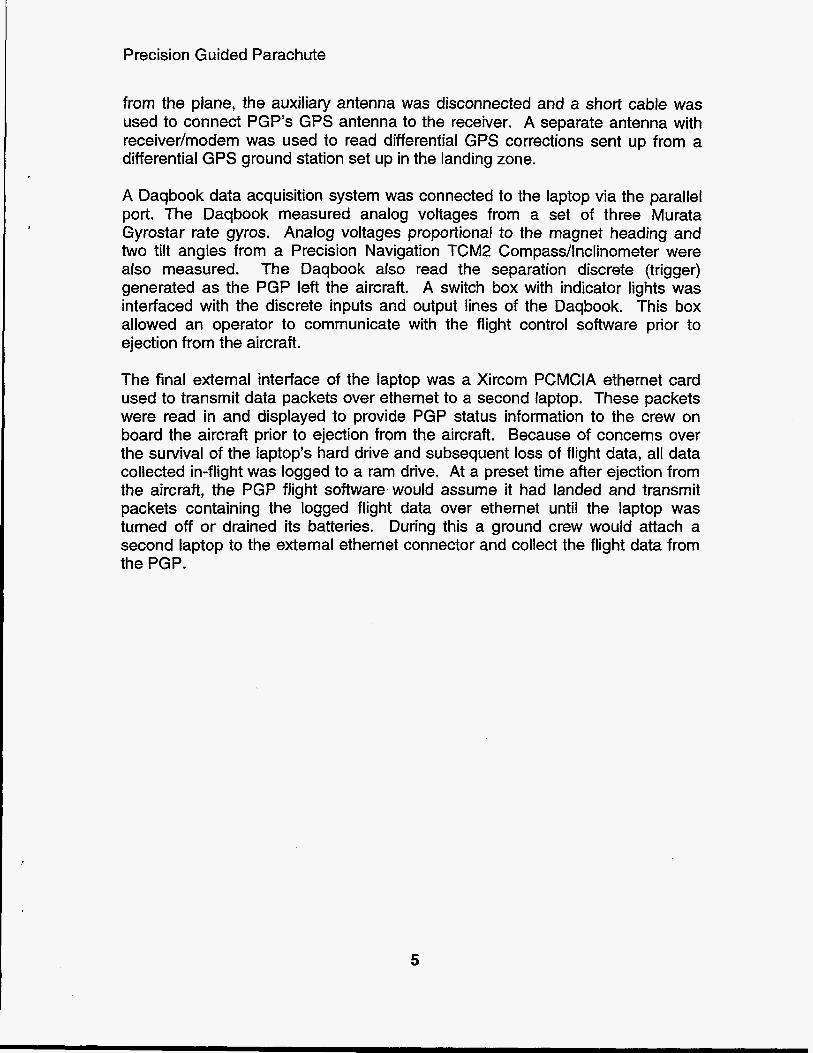
A Daqbook data acquisition system was connected to the laptop via the parallel port. The Daqbook measured analog voltages from a set of three Murata Gyrostar rate gyros. Analog voltages proportional to the magnet heading and two tilt angles from a Precision Navigation TCM2 Compass/lnclinometer were also measured. The Daqbook also read the separation discrete (trigger) generated as the PGP left the aircraft. A switch box with indicator lights was interfaced with the discrete inputs and output lines of the Daqbook. This box allowed an operator to communicate with the flight control software prior to ejection from the aircraft.
The final external interface of the laptop was a Xircom PCMCIA ethernet card used to transmit data packets over ethernet to a second laptop. These packets were read in and displayed to provide PGP status information to the crew on board the aircraft prior to ejection from the aircraft. Because of concerns over the survival of the laptop’s hard drive and subsequent loss of flight data, all data collected in-flight was logged to a ram drive. At a preset time after ejection from the aircraft, the PGP flight software would assume it had landed and transmit packets containing the logged flight data over ethernet until the laptop was turned off or drained its batteries. During this a ground crew would attach a second laptop to the external ethernet connector and collect the flight data from the PGP.
5

Precision Guided Parachute
Aircraft
Antenna
DaqBook - Laptop Data , I Seoaration I /Roll Gyro RtchGvro Acqusition System Yaw Gvro +
* 4 -]Switch Box 1
Antenna T
Magnivox DGPS R mnive r
Reciever Modem
Diff Corr Antenna
t t
I 1 486 Laptop Flight Computer I Parallel Port Serial Port1 Serial Port2
I Ethernet Ethernet I Left Steering
Lanyard
Figure 3: PGP G&C Hardware Block Diagram
:igure 4: PGP Gyros, Compass, Laptop, GPS Receiver (left to right).
6

Precision Guided Parachute
Guidance and control software The flight software consisted of three tasks running simultaneously. The highest priority task was an interrupt service routine that read in GPS data from serial port 1 at 9600 baud and stored it in a buffer. The second priority task was the autopilot routine, triggered by the 18.2 Hz DOS interrupt clock. The autopilot routine generated servo commands for the motor controllers in response to turn rate commands calculated by guidance software running in foreground as a part of the main program. At the lowest priority, the main program would compute turn rate commands based on the most recent GPS position and velocity measurements and send these to the 18.2 Hz autopilot routine.
Each of three tasks logged data to the flight computer’s ram drives. The GPS serial port interrupt service routine logged the raw ASCII string read in from the GPS receiver. The autopilot routine logged the time, all the analog measurements, motor commands, and autopilot intermediate variables. The background main program logged the autopilot commands, wind estimates, GPS position and velocity estimates.
System integration and software validation By interfacing the PGP hardware with the real time simulator, it was possible to develop and test the flight software under conditions similar to those experienced in actual. Thus, the vast majority of system integration problems were encountered and resolved in the lab. The primary benefit was the reduction the of time and expense of resolving these problems in the field. A secondary benefit was ability to investigate the effects on signal noise, latency and disturbances in a controlled manner to produce a more robust design. As new and sometimes unanticipated situations were encountered in the field, the simulation would be enhanced to model them and the flight software would be modified to deal with them.
7

Precision Guided Parachute
Field Testing
Coyote Canyon drop tests In May 1995, a series of tests were conducted at the Coyote Canyon Cable test facility to validate the PGP in the field. A special fixture attached to the cable was used to lift the parachute and hold it open, ready for flight. The parachute could be released by remote control from a signal on the ground. It was planned to make several flights down the canyon in this manner. However, uncooperative winds in the canyon precluded this. In any event, numerous checks of the GPS system, data acquisition system were made while raising and lowering the parachute on the cable.
A drop from a height of 300 feet was made to test the parachute in flight. A drop from a lower altitude would not give sufficient time for the parachute to fully inflate and start gliding flight. Because of uncooperative winds, the parachute was released with a 10 mph tail wind. The parachute stalled and dove towards the ground, leveling out about 100 ft above the canyon floor with a slow turn to the right. The tail wind and dive combined for a hard landing on the right side of the canyon. The flight lasted a total 9 seconds.
Post flight analysis revealed that while motor commands were generated to correct the right turn, no movement of the control surfaces could be discerned from video of the flight. Subsequently, a 1O:l gear reduction drive was added to the servos to increase available torque to move the control surfaces. Other than the servos, all the hardware and software of the PGP performed as expected and was still functioning after the impact with the ground. The Coyote Canyon test provided an opportunity to test many of the PGP components under moderately controlled field conditions, but the unpredictable canyon winds and the narrow constrained landing area of the canyon floor prompted us to forgo additional tests and proceed with airdrops over a large flat drop zone.
b!! =* Figure 5: Coyote Canyon Drop Test Fixture.
8

Precision Guided Parachute
Burris Ranch drop tests Our next field tests were a series of airdrops using the Ross Aircraft Twin Otter to deploy the PGP over the Burris Ranch Dropzone, near Belen NM. Since this was the first time Sandia had made parachute airdrops with the Twin Otter, a detailed test plan was required to satisfy safety requirements for Sandia and DOE (see Appendix B). Burris Ranch was ideal for low altitude developmental flights, but was of limited use due to the proximity of two clusters of inhabited buildings two miles east of the dropzone. Since an impact with these buildings was to be avoided at all cost, airdrops at Burris Ranch were limited to 2000 ft above ground and with winds blowing out of the west. Figures 7 and 8 show the location of the dropzone.
Figure 7: Burris Ranch Dropzone Location Figure 8: Closeup of Dropzone
A total of 9 airdrops were made, the final three of which actively guided by the PGP. Although steady progress was made to a precision landing capability, time and funding expired before a precision landing could be attempted in the field. A precision landing would have required a high altitude airdrop of 5000 f t or more above the ground to give the PGP sufficient time estimate wind conditions, correct for drop point errors and set up the final approach and landing pattern. Plans were made to test the PGP at Sandia’s Tonapah Test Range, however the schedule did not permit this.
Summary of operations at Burris Ranch The first two airdrops were unguided flights with a dummy loads to practice static line parachute deployments from the rear cargo door Twin Otter. Hardware and software problems caused the third and fourth flights to be aborted before ejection from the aircraft. The fifth and sixth flights were successfully deployed from the aircraft; however hardware problems prevented guided flight. Flights 7,
9

Precision Guided Parachute
8 and 9 were successful in commanding the PGP to fly along a commanded heading with a brake maneuver to slow the parachute as it approached the ground. The ninth flight was functionally identical to the seventh and eight flights, with some gain changes in the autopilot increase the responsiveness of the PGP to steering commands.
The following table recounts the problems encountered and progress made during the Burris Ranch operations.
Table 1. Dror, Tests at Burris Ranch
3
- 4
5
6
date 8/17/95
~~
8/22/95
8/29/95
8/3 1 /95
9/07/95
notes Unguided dummy package flown to practice static line chute deployment using Twin Otter aircraft at Burris Ranch Aborted flight, not ejected from aircraft. Problems with the GPS interrupt service routine clashing with the ethernet packet driver. This intermittent problem was not encountered in our initial checkouts.
Resolved by not transmitting packets when the GPS interrupt routine was enabled. A input through the switch box was used to enable and disable this interrupt before jettison from the plane. The interrupt was enabled after reading the separation discrete and disabled at the end of the flight. Aborted flight, not ejected from aircraft. GPS receiver failed to acquire a minimum of 4 satellites required for a 3-D navigation solution. The backup GPS receiver used for this flight was found to be defective. First instrumented flight. GPS receiver momentarily lost the differential link, putting it in 3-D nondifferential mode. An erroneous altitude measurement of 300 ft above ground level triggered an early start of the landing sequence. Opening shock of parachute deployment caused the laptop A/D to fail.
Resolved by configuring the receiver to send messages only when it had a 3-D differential solution. Opening shock may have shorted components of laptop A/D to case. Inside of case was insulated to prevent this. Second instrumented flight. GPS receiver functioned properly. Opening shock again caused an A/D failure with the yaw gyro reading zero. The result was that the guidance algorithm combined with the feedforward path of the autopilot to steer the parachute along the commanded heading based on GPS heading measurements only. Torsional coupling between parachute and fight package observed.
10

Precision Guided Parachute
Resolved by using a simpler autopilot that did not use the gyro measurements and steered the parachute using GPS derived heading measurements only.
7,8 9/12/95 First and second successful guided flights. Autopilot steered parachute along commanded heading. Low autopilot gain caused the parachute to slowly turn to the commanded heading. Following the first flight, parachute was repacked and reflown two hours after the first flight.
9 9/14/95 Third successful guided flight. Gain increased to increase I autopilot response. Autopilot steered parachute along I commanded heading.
-
Detailed description of flight on 9/14/95 This section contains a detailed description of the events and steps the flight software went through on the final and most successful PGP flight. A similar sequence of events occurred during on the other flights.
Two teams separate teams, a ground team and airborne team, were required to support these tests. After meeting at Ross Aircraft early in the morning, the ground team headed to the Burris Ranch Dropzone, set up road blocks and the differential GPS ground station and awaited the appearance of the Twin Otter drop plane.
Meanwhile, the airborne team aboard Twin Otter drop plane powered up the PGP flight package. The PGP's laptop computer started the flight software and sent status information over ethernet to a second laptop. As the Twin Otter approached the Burris Ranch, the differential GPS link was verified using the auxiliary GPS antenna mounted on the aircraft. This process also loaded the most recent satellite almanac into the GPS receiver's memory to reduce the acquisition time after the PGP lost track of all satellites during deployment.
The ground crew radioed up the wind conditions to the Twin Otter and gave the final authorization to proceed with the airdrop. Use the toggle switch box, the airborne team loaded in the commanded heading (225 degrees for flight 9). As the Twin Otter started its final pattern over the target, all cables except the auxiliary GPS antenna were disconnected and the PGP was unstrapped and moved to the rear cargo door of the aircraft. An LED on the external case of the PGP flashed as an indicator that the flight software was still functioning. At 5 seconds prior to ejection, the loadmaster disconnect the auxiliary antenna and connected a short cable to connect the GPS receiver to case mounted antenna. This caused the receiver to loose track of all satellites. Finally, the separation trigger cable was pulled and the PGP was pushed out the rear door of the Twin Otter.
11

Precision Guided Parachute
Figure 9: PGP Airdrop at Burris Ranch (digitized video)
Figure 10: PGP Parachute During Flight (digitized video)
Extensive video from the ground, aboard the Twin Otter and from a camera mounted on the flight package was recorded. From the flight package video, the torsional vibration mode coupling the flight package with the parachute was readily observed. The torsional mode had been observed in earlier unguided flights. This mode would destabilize an autopilot using the yaw rate gyro mounted in the PGP case. Therefore, an autopilot which steered the PGP using only the GPS derived heading measurements was used for all three guided flights.
Ram-air parachutes are designed to deploy at half brake (left and right lanyards at the 0.5 setting) to reduce loads during inflation and reduce the transition time to gliding flight. After the parachute has stabilized, the parachutist releases the brakes by pulling the left and right lanyards past the half brake position and then back to zero brake for full flight. The PGP parachute was packed with a built in turn, with left lanyard at the 0.6 brake position and the right lanyard at the 0.4 position. In the event of a malfunction caused by the shock of deployment where no servo commands could be executed, the PGP would simply turn to the left and spiral into the dropzone instead of gliding a mile or two in a random direction.
After a delay of 30 seconds the flight software commanded a sequence of two 0.75 brake commands to release the brakes and transition to full flight. During this time, the GPS receiver reestablished its tracking loops using the onboard antenna, achieving full differential GPS navigation after 30 to 45 seconds.
After the debraking maneuver, the controller made a reversing right turn. This turn signaled the ground and airborne team the flight software was still functioning. While the parachute was circling to the right, an in flight estimation of the winds was made. While a parachute is flying in a steady turn, the north and east velocity components describe a circle, the radius of which is the
12
Precision Guided Parachute
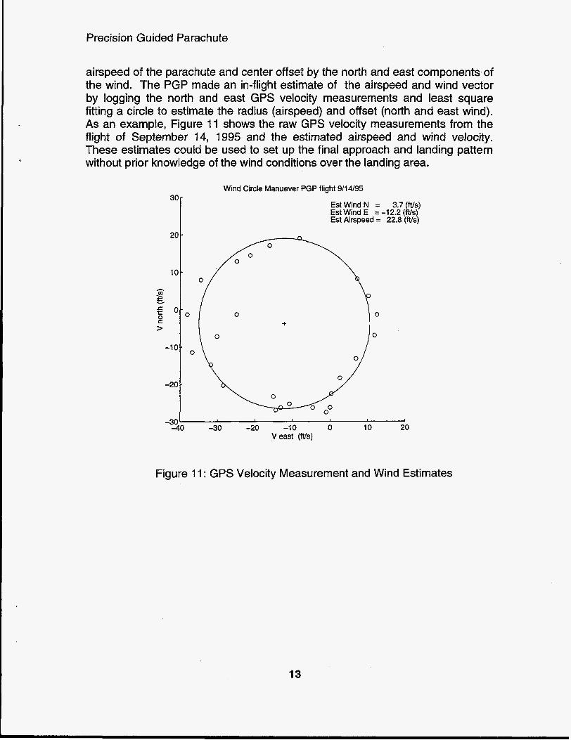
airspeed of the parachute and center offset by the north and east components of the wind. The PGP made an in-flight estimate of the airspeed and wind vector by logging the north and east GPS velocity measurements and least square fitting a circle to estimate the radius (airspeed) and offset (north and east wind). As an example, Figure 11 shows the raw GPS velocity measurements from the flight of September 14, 1995 and the estimated airspeed and wind velocity. These estimates could be used to set up the final approach and landing pattern without prior knowledge of the wind conditions over the landing area.
3c
20
i o - s E O 0 S >
-1 0
-20
-33
Wind Circle Manuever PGP flight 9/14/95
Est Wind E = -12.2 3-7 ( IF) s) EstWindN =
Est Airspeed = 22.8 (Ws)
-30 -20 -1 0 0 10 20 V east (ftfs)
Figure 11 : GPS Velocity Measurement and Wind Estimates
13

Precision Guided Parachute
At 90 seconds after separation, the autopilot was activated and the parachute was steered along a commanded heading using this simple control law:
u = differential control input
@= commanded heading - GPS heading, limited to 1 .O radians
dt = integral error, limited to 0.05 radian-sec
integrator turned off if abs(0) > 1 radian
Kp = 0.20 brakehadian KI = 0.01 brake/(radian-sec)
Figure 12 shows the ground track and Figure 13 the heading errors for the PGP flight of September 14, 1995.
Trajectory PGP flight 9/14/95
2ooo[
1000 Wind Circle
I . Landing
-2000' -2000 -1500 -1000 -500 0 500 1000 1500 2000
East ( f t )
Figure 12: PGP Ground Track Trajectory
14

Precision Guided Parachute
a-
Commanded and Measured Heading PGP flight 9/14/95
. ,,I : .-
' I
- . ,O0I---
Commanded Heading Measured GPS Heading ............
Figure 13: PGP Command and Measured Heading
The parachute continued along the commanded heading until it came within 500 ft of the ground. At this point the parachute added a ramping brake command to the left and right differential turning commands to slow the parachute for a soft landing. The flight software continued to run until 1000 seconds after ejection (more that enough time for these low altitude airdroQs) at which time it assumed it had landed. At this time the software disabled the interrupt routines and shut down the servos. Finally, it repeatedly transmitted the flight data logged on the ramdrive over ethernet until the flight computer was powered down. The ground crew downloaded the flight data over ethernet by attaching a second laptop to the external ethernet connector of the PGP. Once the data was extracted, the PGP was powered down, packed up and driven to the BeledAlexander airport to meet up with the Twin Otter and airborne crew.
Figure 14 is a frame of video taken from the Twin Otter as it circled the PGP from above during the September 14, 1995 flight. During this flight, the PGP was commanded to fly a heading of 225 degrees. The circular feature in the picture is the primary target at the Burris Ranch Dropzone, which the PGP flew directly over (by coincidence) during this flight.
15

Precision Guided Parachute
Figure 14: Video from Twin Otter of PGP over Burris Ranch Dropzone
16

Precision Guided Parachute
Conclusions
Using low cost, commercially available components, a guidance and control system for a ram-air gliding parachute was developed. Extensive use of hardware in the loop simulation allowed the vast majority of problems to be encountered in the lab, greatly reducing the time and expense of field testing to develop this system. Once hardware and software problems encountered in the field were resolved, the PGP demonstrated the ability to fly along an commanded heading angle and make in flight estimates of the wind conditions.
The Flight Test Plan developed by this program to satisfy DOE and Sandia safety requirements established a framework for future programs to use the Twin Otter and Burris Ranch for parachute airdrops.
This program demonstrated that an autopilot can adequately control a parachute without rate gyro information. This greatly reduces the cost and complexity of such systems. If rate gyros are to be used, the torsional coupling between the parachute and the flight package precludes mounting the gyros on the flight package/payload. Future studies should investigate sewing a small gyro package into the canopy to provide angular rate information free of torsional coupling.
17

Precision Guided Parachute
References
[l] Lingard, J.S., “The Aerodynamics of Gliding Parachutes”, notes.
121 Lingard, J.S., “Ram-air Parachute System Design”, 2nd ADS Technology Seminar, 13th AlAA Aerodynamic Decelerator Conference, May 15, 1 994.
[3] Brown, G.J., “Parafoil Steady Turn Response to Control Input”, AlAA technical paper AIAA-93-1241.
[4] Lissaman, P.B.S. and Brown, G.J., “Apparent Mass Effects on Parafoil Dynamics”, AlAA technical paper AIM-93-1 234.
[5] Houge, J.R. and Pierce, D. “Parachute Canopy Control and Guidance Training Requirements and Methodology, AlAA technical paper, AIAA-93-1855.
18

Appendix - A
APPENDIX - A
Project Related Information
Principal Investigator / Program Manager: Jeffrey C. Gilkey, Dept. 2525
Programmatic Details: Project Title: Precision Guided Parachute
Case Numbers: FY94 (3525.070), FY95(3519.280)
Awards: none
Publications and presentations: none
Patents: none
Copyrights (for software): none
Employee recruitment: none
Student involvement: Mark Olguin, SEMY student 1994, 1995
Joe Lucero, SEMY student 1994,1995
Follow-on work: none
A-1


Appendix - B
APPENDIX - B Precision Guided Package Program Test Plan
Precision Guided Package Program
Test Plan
Revision 1 .O, July 20,1995
Author: Mark Dowdican, Dept. 9133 505-845-8499
Contacts: Mark Dowdican, Dept. 9133 505-845-8499 Jeff Gilkey, Dept. 9131 505-844-9401
Sandia National Laboratories
B-1

Appendix - B
Review and Approval
Reviewed by:
Line Representative
Reviewed by:
Organization Date
Safety Engineering
Approved by:
Organization Date
DOE/AL/TSD
Comments:
Organization Date
8-2

Appendix - B
Section I BACKGROUND
1 .I INTRODUCTION
The Precision Guided Package Program is a Sandia internally funded program to design, fabricate, and field test a parachute/package system that can when deployed guide itself to a preprogrammed position on the ground. The parachute/package system consists of a commercial sport glide chute, a Global Positioning Receiver (GPS), a laptop computer, servo motors, interface electronics and nicad batteries for the computer and GPS receiver. The GPS receiver forms a position solution using signals it receives from the GPS satellite constellation and also a GPS differential transmitting station set up within miles of the drop zone. The laptop computer runs control software that takes information from the GPS receiver and its preprogrammed target point and sends control signals to the servo motors that pull on the lanyards of the parachute to make corrections in the package's descent path.
The package part of the system consists of a plastic shipping box. Its dimensions are 27 inches by 34 inches by 34 inches. Its total weight with electronics and parachute is 80 pounds. The parachute is attached to the top of the plastic box and is packed in a commercially available chute pack. To deploy the parachute in flight a static line will be used. The static line will be attached to a hard point in the aircraft and the other end to the chute release pin. This release mechanism is the same as those used by parachutists who jump using a static line.
1.2 OBJECTIVES
The objective of this effort is to take the existing package that has been tested on the ground by simulation and in the air by use of a cable drop test and now test it from a moving aircraft at conditions typical for its design envelope. It is desired to test the parachutelpackage system at two locations. The first location is an Air Force drop zone east of Belen, NM. The drop zone is on the privately owned ranch of Mrs. Elizabeth Burris. This site is suitable for low altitude drops of 500 to 2000 feet above ground level (AGL). The second desired test site is Tonopah Test Range, NV this site is suitable for our final demonstration which we plan on deploying at 5000 AGL.
1.3 PARTICIPANTS and RESOURCES
B-3

Appendix - B
SNL will provide the following resources for this effort:
e
e
e
e
e
e
e
e
e
e
e
Aircraft. The testbed aircraft is a DOE owned, public (Normal) category, DeHavilland DHC-6 Series 300 Twin Otter (serial number 493, registry number N72348). The aircraft is operated by Ross Aviation, a DOE contractor located in Albuquerque. Pilots. The pilots (2) will be responsible for filing the appropriate FAA flight plans and for obtaining permission to fly through restricted areas. These pilots are not required to hold DOE security clearances. The pilots are provided by Ross Aviation. Aircraft maintenance. Aircraft maintenance will be provided by Ross Aviation. Test coordinator. Provided by Dept. 91 33. Loadmaster. Provided by Dept. 2664. An experienced aircraft crew member familiar with Ross Aviation Twin Otter procedures and safety harness hardware. Aircraft liaison officer. The aircraft liaison officer acts as Sandia's official point-of-contact with Ross Aviation. This person will be provided by Dept. 2664. Radio equipment, provided by Dept. 2664. VHF radios will be used for communications between the flight crew and ground based personnel. Safety harness for Loadmaster. This person is responsible for deploying the package, provided by Dept. 2664. Hard point for attachment of static line: Provided by Ross Aviation. Headset with long extension cord for Loadmaster: Provided by Dept. 2664. RF cable to connect the package GPS receiver to an external antenna on the Otter, provided by Dept. 2334.
During this experiment, all SNL and Ross Aviation personnel will operate out of Belen Airport for the Burris Ranch tests. For the Tonopah tests all SNL and Ross Aviation personnel will be based at Nevada. Information on Twin Otter operations are provided in Section 3. Safety related information is provided in Section 4.
B-4

Appendix - B
Section 2 GENERAL INFORMATION
2.1 SCHEDULE AND LOCATION
2.1 .I Time Frame. Because of availability of the Twin Otter all flight tests must be completed between 8/8/95 and 9/15/95. Tests at Burris Ranch are for seen to occur from 8/8/95 to 8/22/95. The Tonopah Test is planned for 9/6/95. For the Burris Ranch drops all missions will probably be morning drops between the hours of 8:OO and 1 I :OO. The number of drops per day will be one or two. For the Tonopah Test there will be a single day for drop tests with the possibility of one drop in the morning and one in the afternoon.
2.1.2 Schedule. The data collection schedule is as follows:
The Burris Ranch Tests will occur on multiple days the schedule below reflects this.
e
e
e
e
e
e e
e e
e
Planning meeting at DOE
Follow up meetings SNL Safety
Final check out of DOE Twin Otter
Transfer of Twin Otter and crew to Belen Airport
Transfer of Sandia personnel and equipment to
Burris Ranch, set up Sandia ground equipment
7/19/95
7/20/95
8/1/95
Each day
Each day
G round chec k-out of parach ute/pac kag e
Pre-experiment briefing for Sandia and Ross Aviation Each Flight
Each Day personnel
Flight # 1 Flight # 2 Flight # 3 Flight # 4 Flight # 5 Twin Otter and all personnel return to Albuquerque
Each day
8/14/95 811 6/95 8/2 1 195 8/23/95 8/28/95
B-5
Appendix - 6
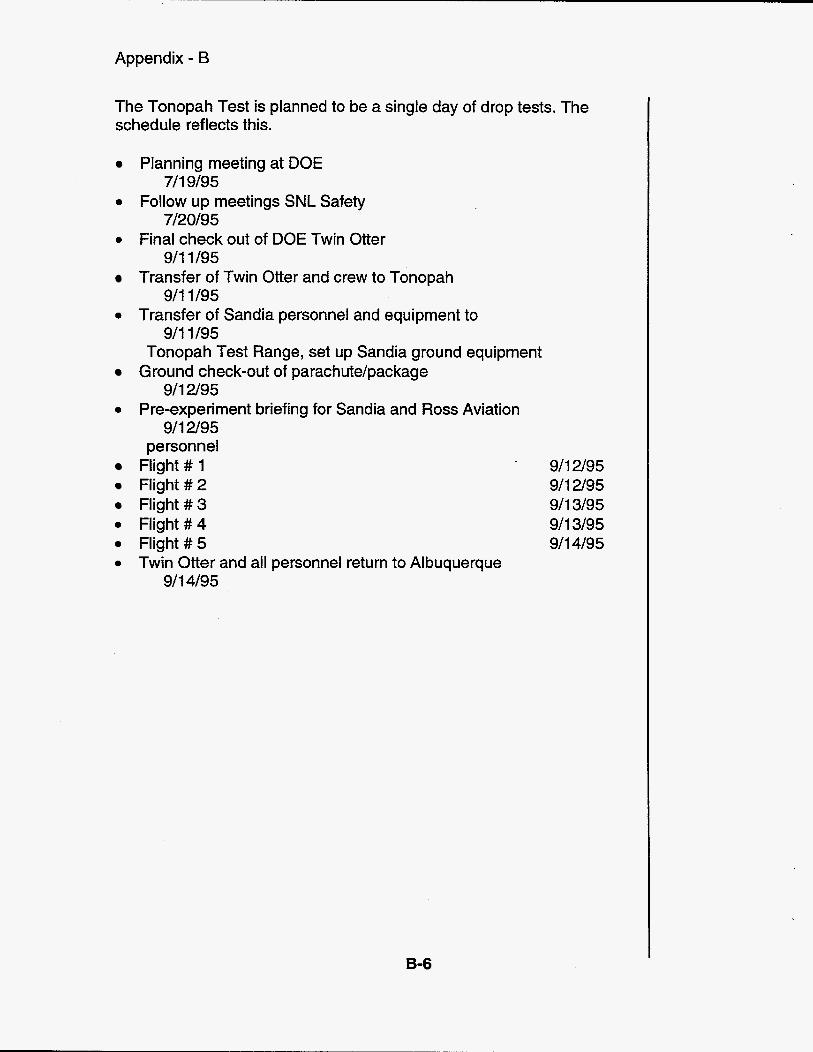
The Tonopah Test is planned to be a single day of drop tests. The schedule reflects this.
Planning meeting at DOE
0 Follow up meetings S N L Safety
0 Final check out of DOE Twin Otter
Transfer of Twin Otter and crew to Tonopah
0 Transfer of Sandia personnel and equipment to
711 9/95
7120195
911 1/95
9/11 /95
911 1/95 Tonopah Test Range, set up Sandia ground equipment
Ground check-out of parachutelpackage
0 Pre-experiment briefing for Sandia and Ross Aviation 911 2/95
911 2/95 personnel
Flight # 1 Flight #2 Flight #3
0 Flight # 4 0 Flight #5 0 Twin Otter and all personnel return to Albuquerque
911 4/95
9/12/95 911 2/95 911 3/95 911 3/95 911 4/95
B-6

Appendix - B
2.1.3 Operations Area.
Burris Ranch Drop Zone: The Burris Ranch Drop zone is located at latitude 34 29' 04.70" N and longitude 106 36' 47.97" W. It is located near two used dirt airstrips. These airstrips appear on aeronautical maps and USGS maps. The USGS map that shows this location is edition 1-DMA, series V781 and sheet 46521. The general area is approximately 15 miles southwest of the city of Belen. It is used on a daily basis by the USAF 58th OSS/DOO wing for parachute drops of sandbags and personnel.
Tonopah Test Range Drop Zone: The designated drop location for the Tonopah test is to be specified by Tonopah Range Safety personnel.
2.2 GENERAL EXERCISE CONDUCT
The following instructions apply to all exercise participants.
2.2.1 Briefings. Briefings will be held as necessary prior to the data collection to ensure that all participants and interested parties are futly informed of the nature of this aviation operation. Briefings and debriefings will also be held on each mission day.
2.2.1 .I before the first Burris drop test at Ross Aviation to review the drop procedures and schedule.
Preoperation Briefings. Briefings will occur one week
2.2.1.2 day to inform participants of that day's objectives, mission windows, and mission parameters. This activity will involve the SNL Test Coordinator, a representative of the Twin Otter flight crew, and representatives from the sensor operator crew. The briefing will be held at the flight operations hangar.
Mission Briefing. A briefing will be held at 7:OO am each
2.2.1.3 the flight operations hangar following the mission. During the debrief, loose ends in mission documentation will be tied up and "lessons learned" will be discussed. This activity will involve the SNL Test Coordinator and other participants as necessary.
Mission Debriefing. A short debriefing will be held at
2.2.2 Individual Run Conduct. The aircraft tracks for each drop run are to have been pre-planned before the actual drop test. Every effort should be made to adhere to the schedule and mission parameters identified during each day's mission briefing. Parameters should not be
B-7

Appendix - B
changed without consulting the SNL Test Coordinator, except in emergencies. Flight tracks are defined in Section 3.8.
2.2.3 Navigation Requirements. Burris Ranch Drop Tests: The Ross pilot will navigate the Twin Otter to the drop zone via VFR. All drop runs at Burris DZ are to be made in a North to South direction. Section 3.8 contains further information concerning the drop flight path. Tonopah Drop Test: The Ross pilot will navigate the Twin Otter to the drop zone via VFR. Drop run paths will be defined by TTR range safety personnel.
2.2.4 Time Standards. Time standards are not an issue with these drop tests.
B-8

Appendix - B
2.2.5 Rendezvous Procedures. Burris Ranch Drops: Ground and air operations personnel are to meet at Belen Airport one and one/half hours before each flight for mission briefings.
Tonopah Tests: Ground and air operations personnel are to meet at the flight operations hangar two hours before the test.
Ground-to-ground, and air-to-ground communications are required for this experiment. Communications are described in Section 2.3.
2.2.6 Safety Considerations. The safety of all participants is of primary importance during flight operations. If flight safety is affected by weather deterioration, air traffic, or equipment failures, the mission will be postponed or canceled. All flight operations will be carried out within the constraints of DOE Order 5480.1 3, "Aviation Safety". Refer to Section 4 for a additional safety related information.
2.3 COMMUNICATIONS
2.3.1 Ground-to-Ground. Ground-to-ground communications will be available by radio as well as cellular and land-line telephone. The radio frequency is 122.85 MHz VHF-FM. This frequency is available for use by Ross. SNL will provide portable radios as necessary.
2.3.2 Air-to-Ground. The DOE Twin Otter is capable of radio communication with ground units on the 122.85 MHz VHF-FM frequency.
2.3.3 Points of Contact: Sandia National Laboratories: Sensing Sys.
Jeff Gilkey (SNL Project Manager) Dept. 9131, Aided Navigation & Remote
Sandia National Laboratories Albuquerque, NM 871 85-5800 Tel. (505) 844-9401 ; FAX (505)844-4157
Mark Dowdican (SNL Test Coordinator) Dept. 9133, Signal & Imaging Processing
sys. Sandia National Laboratories Albuquerque, NM 871 85-5800 Tel. (505) 845-8499; FAX (505) 845-8499
Don Goodrich (Aircraft Liaison)
B-9

Appendix - B
Development Dept.
Ross Aviation: Control Officer) (Twin Otter)
Dept. 2664, Telemetry Technology
Sandia National Laboratories Albuquerque, NM 871 85-5800 Tel. (505) 844-5877; FAX (505) 844-5632
Dave Dudak (Pilot, Configuration
Ross Aviation Inc. P.O. Box 9124 Albuquerque, NM 871 19 Tel. (505) 845-5261; FAX (505) 845-5023
B-10

Appendix - B
Section 3 SPECIFIC INFORMATION for DOE TWIN
OTTER Drop Tests
3.1 INTRODUCTION
To perform these tests the Twin Otter must be flow with its rear door removed. The parachute/package system will be stowed in the back near the removed door. The Otter pilot must be in communication with ground personnel and the deployment person at all times during a drop run to assure a cleared drop zone and that the package is ready for drop. The package must be strapped to the floor of the Otter until just prior to a drop. Normal cargo straps and procedures should be used to accomplish this task. The package's electronics must be turned on in flight prior to deployment to allow loading of flight software and also to allow the GPS receiver to form a solution before deployment. To accomplish the latter the GPS receiver must be connected to the L-band antenna of the Otter so that it can receive signal from the GPS satellite constellation while still in the aircraft.
3.2 AIRCRAFT LOGISTICS
Arrangements for ground accommodations, fuel, auxiliary power, frequency clearances, and other logistical requirements will be made by Ross Aviation or SNL as necessary. Aircraft requirements are:
Ground accommodations: Fuel: Auxiliary power: for equipment basis. Expected use is 1 hr prior to following each flight.
Hangar parking is preferred.
Power cart is required on the ground Jet-A, JP-1 , or JP-4
checkout on a daily and 1 hr
3.3 FREQUENCY MANAGEMENT
Air to Ground: Drops)
Air to Ground:
Differential GPS ground transmitter:
122.85 MHz (Burris Ranch
TBD (Tonopah Test Drops)
413.8 Mhz
3.4 EQUIPMENT DESCRIPTION
B-11

Appendix - B
For these drop tests the Twin Otter must be flown with its rear door removed. This has been done previously by Ross and attached is the "Aircraft Operating Limitation With a Door Removed" document issued by the FAA. The parachute/payload system will be stowed in the back of the aircraft using certified cargo straps until the time of drop. The GPS receiver of the package must be connected to the L-band antenna of the Otter until just before deployment. Section 4 contains safety related issues regarding these drop tests.
3.5 POWER REQUIREMENTS
The parachute/package system runs on its own internal batteries. The computer used to load the flight software into the package during flight also runs on its own internal batteries. Therefore no external power from the aircraft is required to perform these tests.
B-12

Appendix - B
3.6 CREW SIZE
The total crew (including pilots, loadmaster, and Computer Operator) will include 4 personnel. Crew members are not required to hold a DOE security clearance.
3.7 DATA TO BE COLLECTED
The package's miss distance will be recorded by ground personnel when appropriate and only after cleared by the Ross pilot to enter the drop zone.
3.8 FLIGHT TRACKS and INSTRUCTIONS
3.8.1 Operations Area. Section 2.1.3 contains information on the Burris Ranch drop zone and the Tonopah Test Site.
3.8.2 Mission Windows. Section 2.1.1 contains a preliminary schedule for missions. The current plan is to test in the mornings between the times of 8:OO and 1 1 :OO.
3.8.3 Mission Days. Section 2.1 .I contains a preliminary schedule for mission days. The total days actually used will depend on system performance in early tests.
3.8.4 Mission Scrubs. Mission scrubs will be announced by the SNL Test Coordinator at least 1 hour prior to mission start, preferably before crews have left for the airfield.
3.8.5 Calibration. There are not calibration requirements for this flight test.
3.8.6 Flight Tracks. The flight track for the Burris Ranch drop test should be a box pattern. The drop section of the box should be a generally north to south run with the DZ directly in the flight path line. The pilot should always fly a practice box to gain visual of the drop zone. The altitude of the box will vary from one test to the next. The lowest altitude for a test at Burris Ranch will be 500 ft. AGL and the highest will be 2000 ft. The Otter should fly at approximately 90 knots during the box pattern.
The maximum surface wind velocity from any direction that will be allowed for drop tests will be 15 miles per hour. This is the limit used by sport parachutists for inexperienced jumpers.
B-13

Appendix - B
The diagram below depicts the box flight pattern desired for the Burris Ranch drop zones. Over flying the ranch house should be avoided.
B-14

Appendix - B
3.8.7 Other Information. The GPS receiver inside the parachute/package system is required to have a position solution before deployment. To accomplish this the receiver must be turned on 30 minutes before drop and connected to an external antenna of the Otter so that signals from GPS satellites can be received. The deployment person will make these connections and the computer operator will validate that the system is operating correctly.
3.9 SCORING
The package's miss distance will be measured when appropriate. CAUTION: No on will enter the keep out zone until receiving clearance from the pilot in command
3.1 0 PREPARATION AND SHAKEDOWN
The package's GPS receiver will be connected to the L-band antenna of the Otter before takeoff and the system turned on. The receiver will be allowed to form a GPS position solution to determined its functionality. The computer operator will report system readiness to the pilot in command.
3.1 1 CONTINGENCIES
If the package's electronics is not functioning correctly drop tests will be postponed and/or canceled until the problem is corrected.
B-15
Appendix - B
Section 4 SAFETY INFORMATION
4.1 INTRODUCTION
This Safety Plan incorporates all aviation safety related information required by DOE/TSD and SNL Safety Engineering Department 7732. Descriptions of the aviation missions to be performed are contained in other sections of the Test Plan.
4.2 AIRCRAFT
The aircraft to be used in this aviation operation is a DeHavilland DHC- 6 Series 300 Twin Otter. The serial number of the aircraft is 429. The registry number is N35062. It is a Public (Normal) category, twin- engine, aircraft. The airworthiness certificate is attached.
4.3 OPERATOR
The aircraft is owned by the Department of Energy and is operated and maintained by Ross Aviation, Inc., a DOE contractor located in Albuquerque. Ross Aviation is required to conduct flight operations per DOE 5480.13, "Aviation Safety", which refers to title 14, part 135 of the Code of Federal Regulations (14 CFR 135), "Air Taxi Operators and Commercial Operators", for this aircraft. Ross Aviation is also required to adhere to a DOE Operations Manual specific to their operations. Deviations from the DOE Order and from the Operations Manual require specific approval from the DOE.
Ross Aviation adheres to many other Federal Aviation Regulations as well. Certification is maintained per 14 CFR 21, "Certification Procedures for Products and Parts". Airworthiness is maintained as per 14 CFR 23, "Airworthiness Standards: Normal, Utility, Acrobatic, and Commuter Category Airplanes". Maintenance is governed by 14 CFR 43, "Maintenance, Preventative Maintenance, Rebuilding, and Alteration". General operating rules are defined by 14 CFR 91, "Air Traffic and General Operating Rules". Ross Aviation's repair station certification is governed by 14 CFR 145, "Repair Stations".
4.4 EQUIPMENT DESCRIPTION
Items 1-5 will be flown in the Twin Otter for these drop tests. items 6 and 7 are required by ground personnel.
1. Parachute/package System
B-I 6

Appendix - B
-SNL 9131 2. Headset For Loadmaster
3. Safety Harness
4. Static Line for Parachute
5. GPS Cable -SNL 9131 & Ross Aviation
6. GPS Gnd Station Antenna
7. Hand held VHF Radio
-SNL 2664
-SNL 2664
-SNL 2664
-SNL 9131
-SNL 2664
4.5 CREW SIZE
Two flight crew members are provided by Ross Aviation for all aviation operations. Air crew members are provided by SNL; theair crew will be four personnel for these operations.
4.6 MISSION TYPE
These mission involve dropping an object from a moving aircraft at altitudes from 500 ft. AGL to 5000 f t . AGL. These tests involve a single aircraft. The aircraft will not be in restricted areas during the tests. Tests will be during the day with the duration of approximately one hour.
This aviation operation is not expected to exceed the constraints of DOE 5480.13, "Aviation Safety". The following matrix summarizes the types of activities expected to occur during this aviation operation:
Table 4.1: Operations Matrix type of activity yedno
DOE aircraft Yes fixed wing Yes rotary wing no
military or other government aircraft no fixed wing no rotary wing no
charter aircraft no fixed wing no rotary wing no unknown operator no
B-17

Appendix - B
airworthiness certificate FAA Standard FAA Special, Restricted Category FAA Special, Experimental Category DOE Flight Certificate
significant air traffic in the operations area operations in civilian airspace operations in military airspace multiple aircraft involved
flying different patterns at same altitude formation flying
at night over adverse terrain
low level flying at night over adverse terrain
nap-of-the-earth flight at night over adverse terrain
automated terrain following at night over adverse terrain
Yes Yes no no no yes yes yes no no no no no Yes no no no no no no no no
4.7 BRIEFINGS
Briefings will be held as necessary prior to the drop test to ensure that all participants and interested parties are fully informed of the nature of this aviation operation. Briefings and debriefings will also be held on each mission day.
4.7.1 Preoperation Briefings. Briefings will occur one week before the first Burris drop test at Ross Aviation to review the drop procedures and schedule.
4.7.2 Mission Briefing. A briefing will be held at 7:OO each day to inform participants of that day's objectives, mission windows, and mission parameters. This activity will involve the SNL Test Coordinator, a representative of the Twin Otter flight crew, and representatives from the sensor operator crew. The briefing will be held at the flight operations hangar.
4.7.3 Mission Debriefing. A short debriefing will be held at flight operations hangar following the mission. During the debrief, loose ends in mission documentation will be tied up and "lessons learned"
B-18
Appendix - B
will be discussed. This activity will involve the SNL Test Coordinator and other participants as necessary.
4.8 ANALYSIS of HAZARDS
The safety of all participants is of primary importance during flight operations. If flight safety is affected by weather deterioration, air traffic, or equipment failures, the mission will be postponed or canceled. The Ross Aviation Pilot-in-Command, as well as the SNL Test Coordinator, will ensure that aviation operations do not exceed the description contained in the Test and Safety Plans.
The final authority on aviation operations flight safety is the Pilot-ln- Command. In addition, per corporate policy, SNL employees have:
the right and the obligation to refrain from participating in any operations that are believed to be unsafe to people or to the environment (until those operations have been evaluated and determined safe), the responsibility to report unsafe conditions,
0 the authority to halt inappropriate operations that are observed or that are being participated in.
4.8.1 Air Traffic. Safe separation of the Twin Otter from nearby air traffic will be maintained through FAA or military air traffic control and per VFR. Since these tests involve dropping a box attached to a parachute a "Notice to Airmen", NOTAM, must be posted by Ross Aviation with the FAA so that other aircraft are aware of the hazard. Any permits, flight plans or other FAA documentation required for these tests will be the responsibility of Ross Aviation.
In addition to the above, for the Burris Ranch drops the Air Force must be contacted prior to a mission. The Burris Ranch drop zone is used daily by the Air Force for manned drops and sandbag drops. To schedule a drop the commander of the 58th OSS/DOO must be contacted one week before a drop test is to be performed.
B-I 9

Appendix - B
4.8.2 Aircraft Hazards. There are a number of aircraft hazards associated with these drop tests. The first is that the Otter must be flown with its rear door removed to perform these tests. This procedure has been approved by the FAA for Ross and has been done on a previous flight test. A copy of the FAA document entitled "Aircraft Operating Limitations With a Door Removed" is attached.
It is currently planned that other than the pilot and copilot there will be two Sandia personnel in the back of the aircraft. One of these persons is the computer operator. The other person is responsible for deploying the package, this person is referred to as the loadmaster. Because the rear door of the aircraft will be removed the computer operator will be required to remain buckled in his seat for the duration of the flight. The loadmaster will be required to wear a safety harness that prevents him from crossing the plane of the rear door. The safety harness to be used is a full torso harness. The back of the harness has a "D" ring. The "D" will attached to a webbed line that has safety latches on both ends.
The second hazard of these tests involves the securing and releasing of the package. During a majority of the flight the package will be secured to the floor of the Otter using cargo straps. For deployment, however, these straps must be removed. At this point the 150 pound package is no longer secured. It is desirable to keep the time that is condition exists to a minimum. Therefore the package will not be unsecured until the final leg of the box pattern depicted in Section 3.8.6. In addition to this precaution the Otter will be required to always fly a practice box pattern before the actual drop run. This practice drop run will allow the pilot and crew to get a feel for the amount of air turbulence over the drop zone. Of course the package will always be secured during the practice run. If it appears that air turbulence to too great such that releasing the package would represent a hazard then the mission would be aborted.
It is critical for these tests that the pilot have communication with the loadmaster in the aft of the aircraft and the personnel on the ground. If any of these communication links is inoperative then the mission will be aborted. Any of the three individuals (pilot, loadmaster, ground coordinator) in this communication chain can halt a drop with the signal "Abort Abort Abort". When this signal is given the package if unsecured would be immediately secured.
A hazard to the aircraft is the center of gravity (cg) shift associated with the releasing of the package. An analysis of this cg shift has been
B-20

Appendix - B
made and it has been determined to be 0.5 inches forward. This shift is negligible and does not pose a problem to the aircraft.
Another hazard in deploying the package involves the static line that is attached to the parachute and also the aircraft. If by some means the static line causes the package to become "hung" (i.e. the package is not free and is being towed by the Otter) then the loadmaster is required to cut the line thereby releasing the line and package together. It should be noted here that this failure scenario is remote. The static line is attached to the deployment bag of the parachute via rubber bands. These rubber bands do not have the tensile strength to hold the weight of the package.
B-21
Appendix - B
4.8.2 Aircraft Hazards Continued
There is a hazard that also involves the static line and the loadmaster. The hazard is the remote possibility that the loadmaster becomes entangled in the static line. To prevent this from occurring the static must always be coiled neatly near the rear door away from the loadmaster. The coiled static line during the flight must be secured to the floor. Just before deployment of the package the loadmaster must release the static line from the floor. The coils of the static line will be tied together using a low tensile strength wire. This wire will keep the coils from becoming unravel before deployment but will easily break upon deployment. The loadmaster will always visually verify that he is clear of the line before deployment and this will be confirmed by the computer operator who is also located in the back of the aircraft. The loadmaster will announce that he is clear of the line on his headset to inform the pilot. If the pilot does not hear this message he will stop the drop by announcing "Abort, Abort, Abort".
The final hazard also involves the loadmaster and the package. Precautions need to be taken to prevent the hands of the person becoming caught on any part of the package during deployment. To prevent this from happening the loadmaster will only push on the box on premarked positions. These positions will have been chosen such that they keep his hands clear of any hazards. The loadmaster will also be required to wear heavy (thick) leather gloves. It should be noted here that the package is essentially a smooth plastic box with very little to become entangled with. Nonetheless these precautions will be taken.
4.8.3 Altitude. The aircraft may be operated at altitudes (and durations) which do require the use of oxygen for the flights.
4.8.4 Hazards to Ground Personnel. These tests require ground personnel to be present near the drop zone. To assure safety of ground personnel a keep out zone is defined as an area of radius twice the above ground altitude of the aircraft at the time of drop centered on the preprogrammed point of impact. The keep out zone also includes the area on either side of the flight path of the Otter during its drop run. The distance on either side of the flight path is again two times the AGL of the aircraft.
During a drop test at Burris Ranch it will be the responsibility of the Test Coordinator to verify a cleared drop zone. The access road to the drop area will be blocked prior to a test. During each drop run the Test Coordinator will radio via a VHF radio to the pilot that the drop zone is
B-22
Appendix - B
clear. The package will not be unsecured unless this message is received by the Otter.
The Test Coordinator will receive permission from the pilot-in- command prior to entering the area for scoring and package retrieval.
As stated in the Aircraft Hazards section if the communication link between air and ground is not functioning a drop cannot occur. The mission will be postponed/aborted until communications can be established.
4.8.5 Aircraft Access. The list of Sandia personnel having access to the aircraft for this project is identical to the list presently in-force for the STRIP project.
B-23

Appendix - B
4.9 INCIDENT REPORTING
The Ross Aviation Pilot-In-Command is responsible for reporting incidents through Ross Aviation to DOETTSD. The SNL Test Coordinator is also required to report incidents through SNL to DOWAL. In the event that neither of these personnel are able to report the incident, then any available test participant may assume this responsibility. Pertinent contacts are:
Ross Aviation Dispatch (505)
Director, SNL 91 00 Carolyne Hart (505)
SNL Aviation Safety POC Ken Miles (505)
DOMSD Aircraft Safety Bob Steen (505)
DOE/TSD Aircraft Manager Rick Arkin (505)
845-5043
844-9355
845-9807
845-6090
845-6665 58th Special Operations Wing Lt. Col. Rice 846-9850 ext. 236
The person reporting the incident should call through this list in the order shown until, at a minimum, a Ross Aviation contact and an SNL contact have been reached. The reporting person should then remain available to provide additional information to Ross Aviation, SNL, or DOE as necessary.
B-24
Appendix - B
4.10 REFERENCES
References are available on request. 1 "Evaluation of DHC-6 (Twin Otter) in a Sandia "MoComp" Test Configuration", SAN-2, January 30,1991. 2 "Structural Substantiation of an Overhead (Main Cabin) Track Installation", Consulting Aerospace Engineers, Inc. report # SAN-4, February 25, 1991, and 3 "Evaluation of DHC-6 (Twin Otter) in a Sandia "MoComp/STRI PI' Radar Test Aerospace Engineers, Inc. report # SAN-6, February 19, 4 "Structural Substantiation of a Light Weight Electronics Rack in the Cabin of Light Weight Racks for DHC 6", Consulting Aerospace Engineers, Inc. report # SAN-10, February 13, 1 992, and attached FAA Form 81 10-3 approval. 5 (Above the Cockpit) for Engineers, Inc. report # SAW1 1, April 20, FAA Form 81 10-3 approval. 6 Racks for DHC 6", Consulting Aerospace Engineers, Inc. report #
7 the Main Cabin of a DHC-6", Consulting Aerospace Engineers, Inc. report # SAN-10, February 13, 3 approval. 8 (Twin Otter)", SAN-15, March 17,1992, and approval. 9 10 11 Department 2340 Sandia Drawing Number SP471837. 12 Otter Aircraft - 13 Aircraft", Sandia 14 15
Consulting Aerospace Engineers, Inc. report #
attached FAA Form 81 10-3 approval.
Configuration", Consulting 1991.
"Structural Substantiation of a Cutout in the Fuselage Skin Cooling Air", Consulting Aerospace
1991, and attached
"Structural Substantiation of Modifications to Light Weight
"Structural Evaluation of the Installation of a Signal Processor in
1992, and attached FAA Form 81 10-
SAN-14, August 18,1991.
"Structural Evaluation of a Tubular Steel Structure on a DHC-6 Consulting Aerospace Engineers, Inc. report #
attached FAA Form 81 10-3
FAA Form 337, "GPS Antenna Installation", February 26, 1992. FAA Form 337, "EFIS Installation", February 4, 1992. "Operation of the IlT Traveling Wave Tube Amplifiers in
Laboratories and in the Twin Otter Aircraft",
"Preliminary Hazard Assessment, DeHavilland DHC-6 Twin Registry Number N35062", PHA ID# 751 501.
"Safe Operating Procedure for the DHC-6 Twin Otter Laboratory SOP 701 54 9004.
DOE 5480.1 3A, "Aviation Safety", February 23, 1993. place-holder for EMC/SOF check reference.
B-25


DISTRIBUTION:
50 MS 0843 J. C. Gilkey, 2525
1 1436 LDRD Office, 4523
1 901 8 Central Technical Files, 8532-2
5 0899 Technical Library, 441 4
2 0619 Review & Approval Desk, 12630 For DO E/OSTI
DIST-1