Embed Size (px)
Citation preview

Technical Note TN-167 11/05/WH
RAE Systems by Honeywell 877-723-2878 raesystems.com 1
PROPER USE OF DILUTION FITTINGS ON PUMPED MONITORSINTRODUCTION
Gas monitoring instruments can benefit from continuous sample dilution for several reasons, including:
1. Bringing concentrated samples into the linear measurement range of the sensor.
2. Adding enough oxygen to inert sample gases to allow proper function of LEL and electrochemical sensors.
3. Reducing humidity, methane, or other matrix gases that can affect the target gas readings.
4. Reducing possible damage to some sensors at high exposures. For example, a stream contains ~500 ppm benzene, 40 vol% H2, 5 vol% N2, 20 vol% CH4, and 20 vol% ethane,propane and higher hydrocarbons. UltraRAE benzene measurements are desired, but cannot be performed directly because the methane suppresses the response and the high hydrocarbon content oversaturates the RAE-Sep tube. A 20- to 30-fold dilution brings the matrix gas concentrations within an acceptable range while still having enough sensitivity to the benzene.
Another common example is measuring organic vapors in tanks inerted with nitrogen to remove the risk of explosion. In such cases, the oxygen content should be increased to at least 5 vol%, and preferably above 10 vol%, to assure consistent readings. As long as a minimum oxygen concentration is reached, variations in the oxygen level do not affect the LEL readings significantly (see Figure 1).
Dilution Fittings
Tests with isobutylene and show that the 5:1 and 1:1 dilution fittings (p/n 008-3025-000 and 008-3026-000, respectively) can be used if procedures are carefully controlled. The 1:1dilution fitting is simply a Tee that allows the sample to mix with air before entering the instrument. An extension tube/hose is typically used to reach the sample and keep the monitor and dilution fitting outside in normal air.
To install the dilution fitting, attach the male Luer fitting to the female Luer connection of the instrument housing or filter (Figure 3). To connect to a MiniRAE 2000 or ppbRAE probe (Figure 4), cut the Tygon tubing to about 1/2” from the fitting and connect the tubing directly to the probe, making the Tygon connection as short as possible, to avoid absorption losses.
Figure 1. Effect of O2 concentration on LEL measurement.
Figure 2. 5:1 (left) and 1:1 (right) dilution fittings.

Technical Note TN-167 11/05/WH
RAE Systems by Honeywell 877-723-2878 raesystems.com 2
The dilution ratio depends on the length of tubing added (see below). Tables 1 and 2 give the approximate dilution ratios measured using various types of standard tubing. The remote sampling wand provided with the MultiRAE cannot be used with dilution fittings because the flow restriction in the 1/16” tubing is too great.
Caution: The dilution system must be calibrated before use. The ratios in Table 1 will vary with different tubing diameters and may vary with sensor type and flow rate.
Caution: The dilution fittings are designed for use with methane or toxic gases that do not absorb onto Tygon tubing. If used for VOCs, replace the Tygon portions with Teflon as much as possible, or losses may occur.
Table 1. Dilution Ratio & CF of nominal 1:1 Dilution Fitting measured using a MiniRAE 2000 with isobutylene.
Tubing Length from Sample to Dilution
Fitting
2.8 x 4 mm Teflon Tubing
1/4“ x 1/8“ Teflon-lined Tygon Tubing
in ft m Dil. Ratio CF Dil. Ratio CF
7 0.6 0.2 2 3 2 3
60 5 1.5 24 25 18 19
120 10 3.1 47 48 33 34
180 15 4.6 69 70 49 50
Note: The Dilution ratio is defined so that a 1:1 dilution means equal parts sample gas and dilution gas. Therefore, the response is cut in half and the correction factor is 2. Thus, the Correction Factor (CF) is always (Dilution Ratio + 1.0), so at a 2:1 dilution, multiply the reading by 3 to obtain the undiluted concentration.
Table 2. Dilution Ratio and CF measured using a MultiRAE Plus with CO sensor and gas.
Tubing Length from Sample to Dilution
Fitting
1/4” x 1/8” Tygon Tubing Nominal 1:1
Fitting
1/4“ x 1/8“ Tygon Tubing Nominal 5:1
Fitting
in ft m Dil. Ratio CF Dil. Ratio CF
7 0.6 0.2 1 2 13 14
60 5 1.5 9 10 24 25
120 10 3.1 18 19 45 46
180 15 4.6 29 30 58 59
Lower dilution ratios can be obtained by using a narrower Tee or a restriction on the dilution air branch. For example, using a narrower Tee (3/32“, p/n 400-0213-000) with 12’ of 2.8 x 4 mm Teflon sample tubing reduces the dilution ratio from about 55:1 to about 9:1 (CF=10), and attaching 11” of 1/16” x 1/8” Teflon tubing to the dilution branch results in a dilution ratio of about 1:1 (CF=2; see Figure 4).
Figure 3. Connection to an instrument with Luer fittings. Keep the dilution fitting away from the gas outlet port, to ensure clean air is used for dilution.
Figure 4. Connection to a PID with Flex-I-Probe.
Technical Note TN-167 11/05/WH
RAE Systems by Honeywell 877-723-2878 raesystems.com 3
Precautions
1. Must use open tube, open cup, or Tedlar bag to calibrate and measure. No pressure gradients allowed during measurements (sample cannot be in a pressurized pipeline or a fast air stream; the sample must be depressurized to a low flow or a into a bag).
2. Avoid positioning the dilution air inlet near the concentrated sample or the instrument effluent.
3. Don’t hold the dilution fitting by hand during measurements, to avoid humidity changes.
4. The extension tubing can be coiled even to 10 cm in diameter, but there can be no kinks or restrictions.
5. There is no significant effect of moderate changes in total flow rate or attaching tubing to the effluent ports of RAE Systems instruments. Therefore, high or low pump speeds can be used, and it is not necessary to recalibrate the dilution ratio as the pump gets weaker or filters get restricted.
Thus, the user can adjust the dilution ratio by adjusting the length of tubing used. With the 1:1 fitting, one has the added ability to adjust it further by adding tubing to the second branch of the T dilution
fitting. (If a longer extension probe is needed to get to the sample, one can reduce the dilution ratio by adding an extension to the other Tee branch.)
Extension Tubing Material & Diameter Selection
Some extension tubing between the sample gas and dilution fitting is normally required, either to reach a remote sample or to ensure that the dilution air is not contaminated from the sample inlet. Table 1 applies only to 4mm O.D. (2.8mm I.D.) Teflon tubing. If other tubing diameters or lengths are used, the dilution ratio must be calibrated (See Technical Note TN-140 for tubing volume and delay times). Do not use tubing with an inner diameter <1/8” (including the RAE Systems remote sampling wand) because the dilution ratio will be excessively high. Teflon or metal tubing is highly recommend to avoid adsorption losses when measuring hydrocarbons like gasoline by LEL or PID. Tygon extension tubing may be used for non-absorbing compounds like methane, propane, and CO. Short Tygon connecting tubing is okay; for benzene even 10 cm does not cause much loss, but one might want to shorten the length of the Tygon tubing supplied with the dilution fittings or replace it with Teflon.
RAE Systems offers the following 15’ extension tubings with male Luer lock connectors:
Teflon, 2.8mm I.D. x 4mm O.D., p/n 008-3012-151
Tygon, 1/8” I.D. x 1/4” O.D., p/n 008-3012-150
The Teflon tubing often requires a weight to keep it extended. Teflon-lined Tygon tubing offers the inertness of Teflon with the handling ease of Tygon. An extension tube can be prepared from the Teflon-lined tubing (1/8 in I.D. x 1/4 in. O.D., p/n 411-0025-037) and male Luer lock fittings (p/n 400-0073-010).
Calibrating the Dilution Ratio
The ratios given in Table 1 are approximate and should be calibrated if the type or length of tubing used is different, if any non-standard filters or other attachments are made, or if the sample gas is flowing or has slight pressure variations. Dilution ratios can be calibrated using any sensor; a PID or LEL or oxygen sensor are typically the most convenient.
Direct Calibration Using a PID, LEL or Other Sensor
Zero the PID or LEL sensor and attach the hosing and all fittings in the same configuration in which they are to be used during sample measurement. Then calibrate with a standard gas from a Tedlar Bag or open cup through the dilution system. Although the instrument will see the diluted gas, leave the span value at the undiluted concentration. After calibration the display directly
Figure 5. Dilution fitting adapted to give about 1:1 dilution with 12’ of 2.8 x 4mm sample tubing attached.
Technical Note TN-167 11/05/WH
RAE Systems by Honeywell 877-723-2878 raesystems.com 4
reads the concentration of the undiluted sample without needing any correction for dilution (the usual correction is still needed if the sample gas is different from the calibration gas; see TN-106 for PID or TN-156 for LEL). This method works only for small to moderate dilutions because at high dilution there may not be enough gas reaching the sensor to calibrate.
Caution: Recalibrate the sensor if the dilution probe is removed, or else readings will be high.
Correction Factor Calibration Using a PID or LEL Sensor
Zero the PID or LEL sensor and calibrate in the normal way with a standard gas. Then attach the hosing and all fittings in the same configuration in which they are to be used during sample measurement. For an UltraRAE, be sure the benzene RAE-Sep tube is in place. Then measure the calibration gas again through the dilution fitting set-up.
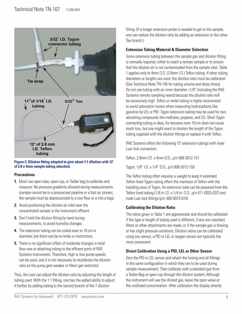
Calculate the Correction Factor (CF) as:
Multiply the readings by the CF to get the original undiluted concentration. For example, if the calibration gas concentration used is 100 ppm isobutylene and the diluted reading is 20 ppm, then the CF = 100/20 = 5 and the dilution ratio is 4:1.
Correction Factor Calibration Using an Oxygen Sensor
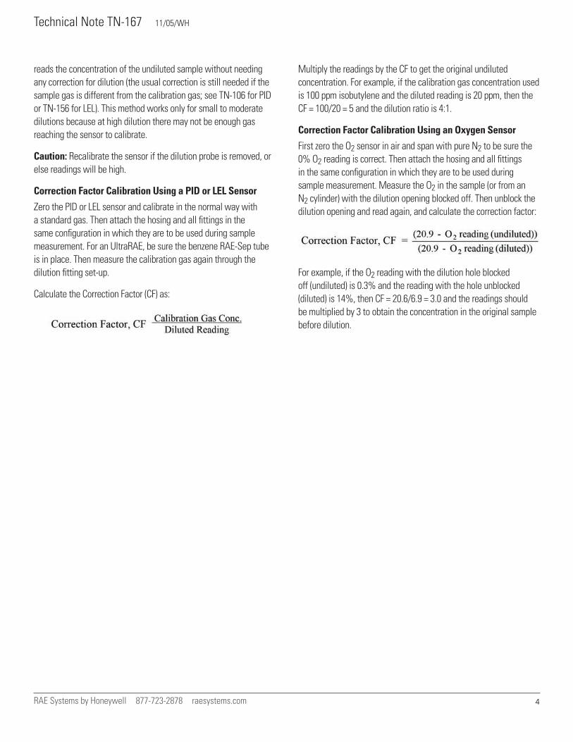
First zero the O2 sensor in air and span with pure N2 to be sure the 0% O2 reading is correct. Then attach the hosing and all fittings in the same configuration in which they are to be used during sample measurement. Measure the O2 in the sample (or from an N2 cylinder) with the dilution opening blocked off. Then unblock the dilution opening and read again, and calculate the correction factor:
For example, if the O2 reading with the dilution hole blocked off (undiluted) is 0.3% and the reading with the hole unblocked (diluted) is 14%, then CF = 20.6/6.9 = 3.0 and the readings should be multiplied by 3 to obtain the concentration in the original sample before dilution.