Embed Size (px)
Citation preview

Caller .comIDID
Technical Manual
For use with Caller ID signaling types:Belcore 202, British Telecom, & ETSI

WHOZZ CALLING? POS 2 Caller ID Monitoring Unit
Technical Manual
For use with Caller ID signaling types: Belcore 202, British Telecom, & ETSI
(V1.0 - 02/15/2006)

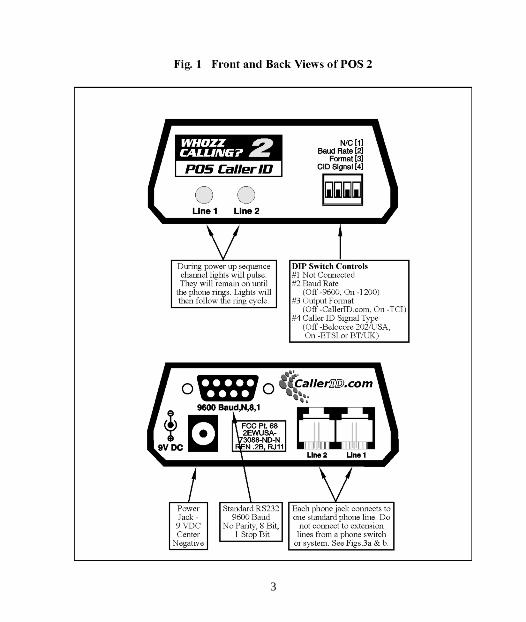
Table of Contents Introduction.................................................................................................................1 Telephone Line and Serial Communication Requirements ......................................... 1 Quick Start Procedure ................................................................................................. 2 Figure 1 - Front and Back Views of the POS2 ............................................................ 3 DIP Switch Settings .................................................................................................... 4
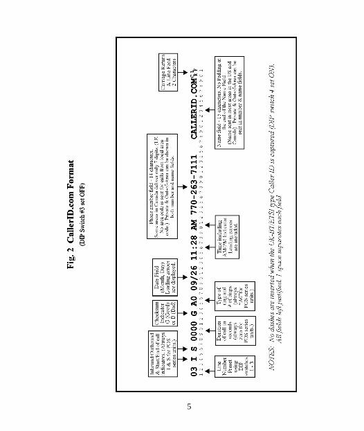
Baud Rate Setting ............................................................................................... 4 Output Format .................................................................................................... 4 Caller ID Delivery Type ..................................................................................... 4 Figure 2 - CallerID.com Output Format ............................................................. 5
Serial Connections and Phone Connections ................................................................ 6 Connecting Directly to a Printer ......................................................................... 6 Connecting to a Computer .................................................................................. 7
Loopback Test for a Serial Port Connection in Windows.......................... 8 Connecting to Phone Lines ................................................................................. 9
4-Wire (RJ14) Phone Cord Connections.................................................... 9 Figure 3a & 3b - Modular Telephone Connections .......................................... 10 Figure 4 - Telephone Connections with a Phone System Switch...................... 11
Specifications ............................................................................................................ 12 Manufacture’s Information........................................................................................ 12 Warranty Information................................................................................................ 13 FCC Information ....................................................................................................... 13 Appendix - RS232 Pin Outs ...................................................................................... 14

Introduction The Whozz Calling? POS reports telephone line number and Caller ID information. Caller ID information consists of date, time, caller’s number and caller’s name (if sent). This information is sent via serial stream to any serial device such as a printer or a computer immediately after Caller ID data is captured. Data can be sent at either 9600 or 1200 Baud. Two different formats are available. The CallerID.com format conforms to all other Whozz Calling? products. The limited format matches the TCI, MLX series format. If multiple units are to be connected together, each individual unit can be set for different line numbers. All options, formats, and addresses are set using DIP switches located on the front panel of the unit. Telephone Line and Serial Communication Requirements The monitoring unit is designed to collect call data from standard telephone lines (trunk or CO lines) coming into your building. It will not work properly if connected to extensions (or station) lines coming from a telephone switch. Connect the unit only to analog loop start, ground start, or Centrex phone lines. It is not designed for ISDN, T1, T3, E1, E3, DID, or Digital Centrex type phone lines The unit can be connected to a printer or to a computer through a serial port. A serial printer connects using a null modem adapter or null modem cable. A parallel printer requires a serial to parallel converter as well as a null modem adapter. If connected to a computer, the serial port must be free of COM Port and IRQ conflicts and dedicated to the monitoring unit. The unit can work with any serial port regardless of the COM number and/or IRQ it is using.
2
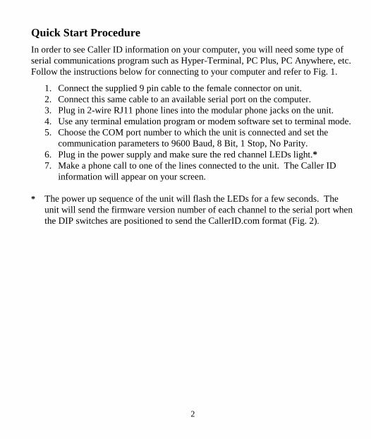
Quick Start Procedure In order to see Caller ID information on your computer, you will need some type of serial communications program such as Hyper-Terminal, PC Plus, PC Anywhere, etc. Follow the instructions below for connecting to your computer and refer to Fig. 1. 1. Connect the supplied 9 pin cable to the female connector on unit. 2. Connect this same cable to an available serial port on the computer. 3. Plug in 2-wire RJ11 phone lines into the modular phone jacks on the unit. 4. Use any terminal emulation program or modem software set to terminal mode. 5. Choose the COM port number to which the unit is connected and set the
communication parameters to 9600 Baud, 8 Bit, 1 Stop, No Parity. 6. Plug in the power supply and make sure the red channel LEDs light.* 7. Make a phone call to one of the lines connected to the unit. The Caller ID
information will appear on your screen. * The power up sequence of the unit will flash the LEDs for a few seconds. The
unit will send the firmware version number of each channel to the serial port when the DIP switches are positioned to send the CallerID.com format (Fig. 2).
3

4
DIP Switch Settings BAUD RATE SETTING The unit can be set to deliver data to the serial port at either 9600 or 1200 Baud. The DIP switch number 2 controls this setting. Refer to the table below. Baud Rate DIP Switch #2 9600 - 1200 ON OUTPUT FORMAT The unit can deliver either the CallerID.com Whozz Calling? format (see Fig 2) or the alternative TCI/Bek-Tel format. DIP switch number 3 control the unit output format. Refer to the table below and Fig 2. Format #3 CallerID.com - TCI/Bek-Tel ON CALLER ID DELIVERY TYPE Caller ID signaling is sent by the local phone company's central office in either of 4 different electronic formats. Belcore 202 signaling is sent between the first and second ring in the countries such as the US, Canada, Mexico, Australia, and others. Caller ID is sent before the first ring by British Telecom (BT) in the United Kingdom. Similarly, Caller ID is sent before the first ring or after a very short ring burst using ETSI signaling that is prevalent in eastern and northern Europe. In countries or regions where older central office equipment is used Caller ID is delivered via DTMF (touch-tones). Contact CallerID.com for a different version of this unit if Caller ID is delivered via DTMF signaling. This unit is capable of capturing either Belcore 202, BT, or ETSI Caller ID signaling.
Caller ID Signaling DIP Switch #4 Belcore 202 (USA) - BT or ETSI ON
5

6
The CallerID.com format is recommended since it is the industry standard. This format is used with all other CallerID.com products with serial output. Several software vendors have adopted this standard since it gives them the flexibility to handle any type of call accounting application. The CallerID.com format provides additional fields for outbound digits dialed, inbound digits dialed after answer, number of rings before answer, call duration, and type of distinctive ring pattern. The Standard Whozz Calling? reports this additional phone call information. Even if your present application does not require this additional information, we still recommend using the CallerID.com format so that future applications may be converted to read the additional data. Please refer to Fig. 2 for the exact format specifications. Serial Connections and Phone Connections The supplied six foot, 9 pin serial cable connects the unit to a serial equipped device such a printer or computer. If your printer or computer has a 25 pin serial port, a 9 to 25 pin adapter is recommended. If connected directly to a serial printer a null modem adapter will be required. These adapters are available at any computer or Radio Shack store. Phone lines are connected to the back of the unit using modular jacks. Input and output ports are provided for wiring systems using 2 wire RJ11 connections. If the wiring coming into your building does not terminate in modular jacks, contact your telephone vendor to add these modular connections. CONNECTING DIRECTLY TO A PRINTER Printers have either a serial or parallel input. Most newer printers use parallel connections. A parallel printer will require a separate serial-to-parallel converter unit. A null modem adapter or cable must be used when connecting a printer directly to the unit. The monitoring unit sends information out on pin 2 while a serial printer or serial-to-parallel converter receives information on pin 3. The null modem adapter reverses the transmit and receive pins by connecting pin 2 to pin 3 and pin 3 to pin 2. A 9-25 pin adapter may also be required and is available at any computer or Radio Shack store.

7
Serial printers are available from only a few manufactures. Okidata Corporation carries at least 2 different models. Ask for Model 590 with serial option or Model 395 with serial option. Set your printer to 9600 Baud, 8 Data Bits, 1 Stop Bit, and No Parity. The unit sends both Carriage Return and Line Feed commands, so the printer should be set to No Automatic Line Feed. CONNECTING TO COMPUTER You may have purchased a software package designed to work in conjunction with the Whozz Calling? unit. The software may have a built-in automatic search and find function. This routine will search all COM and IRQ numbers in an attempt to determine settings for the serial port to which the unit is connected. If an error message indicates that the software cannot communicate or “find’ the unit, you will need to run the Loopback Test below to determine if communication port conflicts exists within you computer. If your software requires a manual selection of the COM and/or IRQ settings, the Loopback Test is also helpful in determining these parameters. The unit should be connected to the serial port, placed in a convenient location next to the computer, and your software installed. Permanent installation and phone line connections can be made once communications between the software and hardware is established. Plug in the power to the unit and run the software. Phone lines need not be connected at this time. Your software will require that you set the COM port number to which the unit is connected. Try different COM numbers to establish communication. If no communication can be established then chances are the serial port is not configured correctly or the COM port number and/or IRQ number defined for the serial port conflicts with another device such as an internal FAX/ modem. To determine whether a serial port is configured and working properly use HyperTerminal in Windows and Loopback test procedure on the following page.

8
Loopback Test for a Serial Port Connection in Windows 1. Make sure your software program that runs in conjunction with Whozz
Calling? is closed. 2. From your Desktop Select Start and then Run.
Type: HyperTrm.exe and select :OK 3. In the Connection Description dialog box Type: Test on the name line and
Select: OK 4. In the Phone Number dialog box leave phone number blank and Select: Connect using Direct to COMx. Where “x” represents the COM port
number being tested (ex. 1,2,3, etc.) Select: OK 5. In the Properties dialog box Select Bits per second: 9600, Data bits: 8, Parity:
None, Stop bits: 1, and Flow Control: None. Then Select: OK 6. Select: File/Properties. In the Test Properties dialog box select the Settings
tab and set Emulation to ANSI. Select ASCII Setup and make sure that Echo typed characters locally box is not checked. Select: OK to close and OK
again to close the Test Properties box. 7. Disconnect the serial cable from the unit, and attach the supplied Loopback
Connector to the cable (the other end is connected to the serial port on the PC). 8. Type any character. a. If the character you typed shows on the screen, the serial port is functioning
properly, the test is positive. b. If you do not see the character COM port and click OK. c. Select: Call/Connect and type any character again and repeat above as
necessary. 9. If you obtain a positive result, close HyperTerminal and run your software
again. If not, you may have a conflict between your serial port settings and an internal device such as a FAX/modem. Consult your computer technician to resolve the conflict.

9
CONNECTING TO PHONE LINES The unit will only capture Caller ID when connected to the central office phone lines coming into the building. The unit will not function properly when connected to extension lines from a telephone switch. If your wiring is modular, simple modular splitters will be required to form a "Y" or branch circuit such that each phone line can connect to the Whozz Calling? POS 2 unit in parallel. If your existing telephone wiring is not modular, consisting of "punched down" solid wire connections, it is recommended that a qualified telephone technician adapt modular connectors for the installation. Figure 4 diagrams the parallel connections required for proper installation. 4-Wire (RJ14) Phone Cord Connections Most modular phone cords contain 4 wires which can supply two phone lines (2 wires for each line.) Your system may have either 2 of the wires connected (RJ11 - 1 phone line) or four wires connected (RJ14 - 2 phone lines). The modular connectors on the unit are equipped to handle only 2-wire RJ11 connections. If you have a 4-wire (RJ14) system, consult with a telephone technician to convert them to a compatible 2-wire RJ11 system.

10

11

12
Specifications Supply Voltage: 9 VDC, center negative Supply Current: Less than 250 mA Loop Current Draw: Less than 1 mA Loop Voltage: 30 to 105 VDC Ringing Voltage: 60 to 130 VAC Insertion Loss: Less than 0.3 dB Voltage Drop: 2.7 VDC at 20 mA loop current Ringer Equivalence: (REN) 0.1 B Dimensions: 4.3" x 3.25" x 1.5" Manufacture’s Information CallerID.com 3107-D Medlock Bridge Road Norcross, GA 30071 Sales (800) 240-4637 Customer Service (770) 263-7111 FAX (770) 263-0049 Web Site www.callerid.com

13
Warranty Information CallerID.com will repair this product with new or rebuilt parts, free of charge, when returned shipping prepaid to the CallerID.com repair facility in Norcross, GA within 12 months from the date of original purchase. This warranty is extended only to the original purchaser. A purchase receipt or other acceptable proof of purchase date will be required before warranty service is rendered. This warranty covers failures due only to defects in materials or workmanship occurring during normal use. It does not cover damage which occurs in shipment; failures which are caused by products not manufactured by CallerID.com; failures which result from accident, misuse, abuse, neglect, mishandling, misapplication, alteration, modification or unintended use of product; service by anyone other than an authorized CallerID.com repair facility; or damage attributed to an act of God. Lightning is considered an act of God. CallerID.com makes no other warranty, either expressed or implied, with respect to this product. If a problem develops concerning this product, contact CallerID.com directly for a Return Material Authorization (RMA). FCC Information This unit is designed to conform to federal regulations and complies with Part 68 of the FCC rules. On the back of this equipment is a label that contains the FCC registration number and ringer equivalence number (REN) for this equipment. Upon request, you may have to provide the FCC registration number and the REN to your telephone company. The ringer equivalence number (REN) is used to determine how many devices can be connected to your telephone line. In most areas, the sum of the RENs on any one line should not exceed 5. If too many devices are attached, your phones may not ring properly and other devices on the line may not detect the ring signal. In the most unlikely event that your unit causes significant problems on the telephone line, the telephone company can disconnect your service. The telephone company will attempt to notify you in advance and will advise you of your right to file a complaint with the FCC.

14
Appendix - RS232 Pin Outs When the serial port is configured to “No Flow Control”, only Transmit and Ground connections are required. Pin 7 and Pin 8 need to be connected only if other serial flow control types are selected. Computer DB9/M Serial Port Monitoring Unit DB9/F Pin 1 (Carrier Detect) Pin 1 (No Connection) Pin 2 (Receive ) Pin 2 (Transmit) Pin 3 (Transmit) Pin 3 (Receive) Pin 4 (Data Term. Ready) Pin 4 (No Connection) Pin 5 (Ground) Pin 5 (Ground) Pin 6 (Data Set Ready) Pin 6 (No Connection) Pin 7 (Request to Send) Pin 7 (Internal Pin 8 (Clear to Send) Pin 8 Connection) Pin 9 (Ring Indicator) Pin 9 (No Connection)

3107-D Medlock Bridge Road, Norcross, GA 30071 800.240.4637 770.263.7111
Caller .comIDID