Embed Size (px)
Citation preview

QUICK LINE
TECHNICAL MANUALPipes and fittings for compressed air
C016 May 2011 - SCS

QUICK LINEpipes and fittings for compressed air
QUICK LINEpipes and fittings for compressed air
3
C O N T E N T S
• Applications• Pipelines Colors guideline• Plant Design• Pipelines Length• Air flow and pressure drop• Ring Pipelines Sizing Example • Materials Features• Chemical Resistence• Application Limits -Temperature/Pressure Ratio• Linear Thermal Expansion and Contraction • Compensation of Expansion and Contraction• Pipelines Bracketing• Safety Directions• AIRCOM Warranty• Pipelines testing• Compressed Air Plant Efficiency and energy saving
PRODUCT DESCRIPTION pag 4
SPECIFICATIONS pag 6
APPENDIX C - AIRCOM ACCESSORIES TECHNICAL SPECIFICATIONS
APPENDIX B - QUICK LINE SYSTEM TECHNICAL SPECIFICATIONS
APPENDIX A - INSTALLATION GUIDE
66789
1112131415171819192021
Information provided in this document were compiled according to our science and conscience and are representative of state of art. Information, data and pictures of Aircom products here in supplied are not binding and are supplied as a guide only. We reserve the right to introduce possible technical modifications without notice. We recommend to always check effective suitability of the product's for the intended use. Any reprint or copying of this document and its annexes, or of part of them, requires prior written consent from Aircom. All rights reserved. (E. and O. E.)

The constant development of plants, the growth and the modifications of factories, the production technology progress, the strong push to automation are asking for pressured air plants correctly sized and easy modifiable.The AIRCOM QUICK LINE was expressly designed and developed for the delivery and distribution of compressed air.Materials and connection peculiarity allow the assembling of flexible plants; these can be integrated by all the Aircom components and work out all the problems and the needs of the more complex plants.Perfect hydraulic seal, remarkable mechanical endurance and efficiency in the time are guaranteed, in spite off the easy and quick installation.
QUICK LINEpipes and fittings for compressed air
4
PRODUCT DESCRIPTION
CORROSIONThe special aluminum alloy of pipes, coated by hot electroctrostatic paint, the aluminum alloy and special coating of cast injected fittings, the tecnoplymers of QUICK LINE fittings and components, create a corrosion-free pipeline both in internal and external surface. This guarantee, at least, 50 year life of the product under normal working conditions.
IMPACT RESISTANCE The materials guarantee excellent performance relating to mechanical resistance and internal pressure resistance. The pipeline can support violent impacts.
U.V. RAYSU.V. rays do not affect aluminum. For this reason the QUICK LINE pipes and aluminum fittings can also be installed outdoors. Quick line technopolymer is for indoor installation only.
FIRE RESISTANCE The aluminum alloy of the pipes allows an excellent fire resistance (flames cannot spread or progress)
AIR DELIVERYBecause of the low friction factor and the large inside pipe section, the AIRCOM QUICK LINE offers higher air delivery then others pipes at the corresponding inside diameter.
INSTALLATIONAIRCOM QUICK LINE allows the highest flexibility and integrability to any other kind of system and, off course, to all the others AIRCOM systems. The absolutely quick and easy installation allows to get "zero" waiting time before pressurizing the system.
DIMENSIONS AND STANDARDAll the items of AIRCOM QUICK LINE are in accordance to adapt to USA standards as regards to pipes, fittings and valves under pressure.
COMPRESSORS OIL COMPATIBILITYNormally the AIRCOM QUICK LINE components can work with a large range of lubricating oils for compressors. A detailed list is continually updated. Contact AIRCOM for compatibility list.
ALL THE AIRCOM ITEMS ARE GUARANTEED "SILICON FREE"
QUICK LINEpipes and fittings for compressed air
2 Quick Line Dn 20 - 3/4” PN 13 Bar 200 PSI - 174 PSI for Canada 21/07
Production - batchMaximum workingPressure - PSI
Supplier/line id. code
Nominal Outside diameter (mm - in)
Product LineMaximum working pressure - bar
MARKING OF ALUMINUM QUICK LINE PIPE
Pipe marking is black ink painted
PRODUCT VISUAL IDENTIFICATIONThe pipe color identifies the carried fluidAircom Blue Pipe: Compressed AirAircom Green Pipe: Other Industrial FluidsAircom Grey Pipe: Vacuum
Logo
Date Stamp Logo
Date Stamp
MARKING OF FITTINGS

RAL
QUICK LINEpipes and fittings for compressed air
Compressed Air
Inert Gases
Vacuum
Water and Industrial fluids
APPLICATIONS1. COMPRESSED AIR
AIRCOM QUICK LINE system is mainly dedicated to COMPRESSED AIR distibution up to a maximum pressure of 200 PSI.
The wide range of products allow do develop plants starting from compressor, through the treatment units, through the distribution ring, up to the peripherical connections.
A set of special components allow quick and effective solutions for all the specific installation problems related to commpressed air.
AIRCOM QUICK LINE system is perfectly integrable with all the others Aircom product ranges as CLASSIC Line.
2. OTHER USES
. Inert gases
. Vacuum
. Water (not for Food & Beverage) and industrial fluids
TECHNICAL SPECIFICATIONS
Fire estinguishing
Water
Steam
Air
Combustible end/or Inflammable Mineral Oils
Gaseous or Liquified Gases (air excluded)
Acids
Dangerous Fluids
Vacuum
3000
6032
9006
-
8007
1024
2010
1021
7001
Fluid Basic Color
Colors of the most common fluids
Pipelines Distiguishing ColorsThe Standard settles the colors in order to identify the carried fluid.

QUICK LINEpipes and fittings for compressed air
7
PLANT DESIGNThere are two ways to design a distribution system: through a single way pipeline (the line starts from the compressor following all the connections up to the farthest one) or through a closed ring (the line starts and returns to the compressor). The ring is usually the advisable solution because of a more equilibrate delivery and because it makes possible, with valves, to cut parts af the plant in order to set, modify, or enlarge the pipeline without complete stop of the air delivery in the firm.
The volume of the ring-line forms an air-storage, helping to keep the pressure value constant, especially during strong and sudden air demands.
To calculate the diameter and length of the main pipe ring, we must know all detailed data of each tool, machine, equipement etc. regarding the air comsumption, usually expressed in cubic feet per minute (cfm), and the correct working pressure value (min and max).
Several factors must be considered to determine the correct sizing of a main line distribution circuit, such as:
1. Air Flow RateThe flow rate is estimated on the basis of the different users as well as on the operation frequency of all users ; the total average flow rate of all off takes will show the the maximum necessary quantity for the main pipeline. A certain precautionary increaseand an estimate of future increase is to be added to the above value.
This data will allow us to size the compressor to be installed and consequently other necessary elements ( receiver, main filter, oil separator, drier etc.).
3. Working Pressure and Loss of Charge
The design must meet the minimum required pressure for each user and its location: far from compressor the available pressure will decrease because of many reasons:
- Air driers, filters
- Drop legs
- Restrictions (valves etc.)
- Frictions from air velocity
- Pipe section changes, directional changes, elbows, fittings and other accessories
In order to get the correct sizing, we must think of pressure losses due to fittings.This value is determined according to the quantity and the shape of the item (see page 8).
2. Compressors - Indicative Air Delivery
The following table shows the air delivery values available for compressors. KW1.534
5.57.511
12.5151822293745557492110132170200
hp246
7.510151720253040506075100125150180230270
cfm9
15203545657595
110130170205260315445555665780960
1150

QUICK LINEpipes and fittings for compressed air
8
PLANT LENGTH When we know the service pressure, the required flow and the length of the pipe from the compressor line to the most distant air user (considering the sum in feet of the equivalent lengths - see table 1), we will be able to calculate the correct sizing of the main pipe header.
If the instant flow rate is equal or inferior to the one produced by the compressor and the ring is shorter than the suggested for a given pipe diameter, the pressure loss will not exceed 5%.
We recommend to use larger pipelines for possible future expansions and to avoid excessive compressed velocity air inside the piping system.
The table below indicates the correspondence to feet of pipe for every assembled fitting. The equivalent length obtained from all fittings will be added to the average length of the installed pipe.
ALUMINUM PIPE DIAMETER SELECTIONValues referred to a 120 Psi pressure and a maximum pressure drop of 5%
Distance between the compressor and the farthest point in feet, NOT total length of distribution ring
ACCORDING THE TABLE ABOVE THE MAXIMUM PRESSURE DROP WILL BE APPROX 5%
Cf / h1260189025203675525073509450
12600178502520037800441006510094500
cfm2132426188
123158210298420630735
10851575
80’1616202525323240405050636380
320’1620252532323240405063638080
160’2020253232404040505063638080
480’20252532324040505063638080
640’25253232404050505063808080
960’252532404050505063638080
1280’253232404050506363808080
1600’2532324050505063638080
3200’32404050506363638080
Values are equivalent to feet of pipe
Table C
*
QLAPL
6.6
10
13
QLGO45PA
3.3
4.3
5
6
7
QLTRPA
6
8
11
18
QLRIDPA
2.4
4
6
QLMAPA
0.3
0.7
1
1
1.3
1.6
2.3
QLGO90PA
2.3
4
6.6
10
12
14
16
21
QLTEPA
0.3
0.7
1
1
1.3
1.3
1.6
1.6
QLMNPA
0.3
0.7
0.7
1
1
1.3
1.3
1.3
QLDERPA
6.6
10
13
20
23
30
0.7
1 6
2 0
2 5
3 2
4 0
5 0
6 3
8 0
- 1/2
- 3/4
- 1
- 1.1/4
- 1.1/2
- 2
- 2.1/2
- 3
*
Example: A 735 cfm system who’s farthest point is 480 feet away from the compressor would require pipe diameter of 80 mm
16 20 25 32 40 50 63 80 mm1/2” 3/4” 1” 1.1/4” 1.1/2” 2” 2.1/2” 3”
QUICK LINEpipes and fittings for compressed air
9
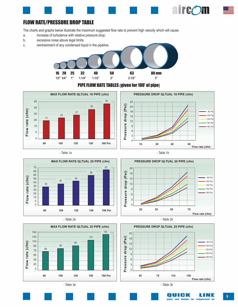
FLOW RATE/PRESSURE DROP TABLEThe charts and graphs below illustrate the maximum suggested flow rate to prevent high velocity which will cause:a. Increase of turbolence with relative pressure drop;b. excessive noise above legal limits;c. reintrainment of any condensed liquid in the pipeline.
PIPE FLOW RATE TABLES (given for 100’ of pipe)
Flow
rat
e (c
fm)
Pre
ssur
e dr
op (
Psi
)
- Table 1a - Table 1b
Flow rate (cfm)
PRESSURE DROP QLTUAL 20 PIPE (cfm)MAX FLOW RATE QLTUAL 20 PIPE (cfm)
20 35 55 75
Flow
rat
e (c
fm)
Pre
ssur
e dr
op (
Psi
)
- Table 2a - Table 2b
Flow rate (cfm)
PRESSURE DROP QLTUAL 25 PIPE (cfm)MAX FLOW RATE QLTUAL 25 PIPE (cfm)
55 75 110 150
Flow
rat
e (c
fm)
Pre
ssur
e dr
op (
Psi
)
- Table 3a - Table 3b
Flow rate (cfm)10 20 30 50
PRESSURE DROP QLTUAL 16 PIPE (cfm)MAX FLOW RATE QLTUAL 16 PIPE (cfm)
90 100 120 150 180 Psi
90 100 120 150 180 Psi
90 100 120 150 180 Psi
22
20
18
15
12
9
6
3
0
20
18
15
12
9
6
3
0
20
18
15
12
9
6
3
0
90 Psi
100 Psi
120 Psi
150 Psi
180 Psi
90 Psi
100 Psi
120 Psi
150 Psi
180 Psi
90 Psi
100 Psi
120 Psi
150 Psi
180 Psi
90 Psi
100 Psi
120 Psi
150 Psi
180 Psi
45
35
30
20
15
5
0
75656050453530201550
150
130
110
95
75
55
35
20
0
2124
27
34
40
3540
46
56
67
6980
90
112
133

QUICK LINEpipes and fittings for compressed air
10
Flow
rat
e (c
fm)
Pre
ssur
e dr
op (
Psi
)
- Table 4a - Table 4b
Flow
rat
e (c
fm)
Pre
ssur
e dr
op (
Psi
)
- Table 5a - Table 5b
Flow
rat
e (c
fm)
Pre
ssur
e dr
op (
Psi
)
- Table 6a - Table 6b
Flow
rat
e (c
fm)
Pre
ssur
e dr
op (
Psi
)
- Table 7a - Table 7b
PIPE FLOW RATE TABLES (given for 100’ of pipe)
Flow rate (cfm)
PRESSURE DROP QLTUAL 60 PIPE (cfm)MAX FLOW RATE QLTUAL 60 PIPE (cfm)
Flow rate (cfm)
PRESSURE DROP QLTUAL 50 PIPE (cfm)MAX FLOW RATE QLTUAL 50 PIPE (cfm)
Flow rate (cfm)
PRESSURE DROP QLTUAL 40 PIPE (cfm)MAX FLOW RATE QLTUAL 40 PIPE (cfm)
Flow rate (cfm)
PRESSURE DROP QLTUAL 32 PIPE (cfm)MAX FLOW RATE QLTUAL 32 PIPE (cfm)
130 185 260 315
220 295 405 555
370 555 740 1110
740 1110 1665 2220
90 100 120 150 180 Psi
90 100 120 150 180 Psi
90 100 120 150 180 Psi
90 100 120 150 180 Psi
90 Psi
100 Psi
120 Psi
150 Psi
180 Psi
90 Psi
100 Psi
120 Psi
150 Psi
180 Psi
90 Psi
100 Psi
120 Psi
150 Psi
180 Psi
22
20
18
15
12
9
6
3
0
22
20
18
15
12
9
6
3
0
20
18
15
12
9
6
3
0
20
18
15
12
9
6
3
0
90 Psi
100 Psi
120 Psi
150 Psi
180 Psi
33529526022018515011075350
595
520
445
370
295
220
150
75
0
1110
925
740
555
370
185
0
2220
1850
1480
1110
740
370
0
9451093
1293
1531
1823
489564
640
791
941
255294
334
412
491
143166
188
232
277

A
2.6 Psi : 100 ’ = Δp : L Δp = 2.6 Psi x 200 ’ = 5.2 Psi 100 ’
Flow
rat
e (c
fm)
- Table 8a
QUICK LINEpipes and fittings for compressed air
11
PIPE FLOW RATE TABLES (given for 100’ of pipe)
Distribution sizing example and pressure drop calculation in a Quick Line network
Having a ring of 300 feet length the most distant point, in the pipeline lay-out, from the compressor will be:300 feet /2 = 150 feet (point “A”)
If we compare this (150 ft) value with the flow rate indicated in Table 5a (page 10) we shall obtain the pipe size we have to install (in this case 40 mm or 1.1/2”).
To know the pressure loss at point “A” we have to calculate the equivalent length (L) plus half the quantity of fittings at the given pressure loss (see page 8):
If in table 5b we cross the flow rate of 210 cfm at 206.3 feet, the correct pipe selection is a 40 mm pipe with the curve at 120 Psi we get a pressure loss (Δp) of 2.6 Psi for each 100 feet of pipe.Then on Table 5b the curve at 170 Psi for 210 cfm = 2.6 Δp
The pressure loss is lower than 5%.In this calculation we did not consider pressure drops due to the possible presence of treatment groups : air drier, filters, etc. These values may be found on the instructions manual of the machine or may be requested to the machine supplier.
Pre
ssur
e dr
op (
Psi
)
PRESSURE DROP QLTUAL 80 PIPE (cfm)MAX FLOW RATE QLTUAL 80 PIPE (cfm)
Service pressure = 120 PsiNeeded Flow Rate = 210 cfmPipeline Length = 300 feet
L = 150 ’ + ( 1‘ x 6) + ( 12’ x 4) + ( 1.3‘ x1) + ( 1’x1) = 206.3 ’
- Table 8b
Flow rate (cfm)1480 2220 3150 407590 100 120 150 180 Psi
90 Psi
100 Psi
120 Psi
150 Psi
180 Psi
22
20
18
15
12
9
6
3
0
37053335296525952220185014801110740370
0
17261994
2259
2794
3327
50 feet
100 feet
COMPRESSOR

QUICK LINEpipes and fittings for compressed air
12
MATERIALS AND REFERENCE STANDARDS
Quick Line SystemPipe
Ring nuts up to dia. 63 mmRing nuts dia. 63:80 mmBodies up to dia. 63 mmBodies dia.63:80 mmBushingClamping ringO-ring sealAluminum bodies and jointsThreaded insertsManifold bodiesQuick drop bodiesPipe bracketsM8 hanger boltsPipe bracket spacersBracket systems
MaterialAluminum extrusion Alloy EN AW T6 UNI-EN 755-2 with inside and outside titanium-based, chrome-free and RoHS-complying treating and electrocoated outside surfacePolyamide 6Aluminum Alloy EN-AB 46100Polyamide 6Aluminum Alloy EN-AB 46100Poliamyde 6Stainless steel AISI 301NBR 70 (Viton® on request)Aluminum Alloy EN-AW 2011 Aluminum Polyamide 6 glass fiber 15%Polyamide 6PolypropyleneGalvanized steelPolypropyleneGalvanized steel
Reference StandardsUNI-EN 755-2
ISO 1043UNI-EN 1676ISO 1043UNI-EN 1676ISO 1043UNI-EN 10088ISO 1043UNI-EN 755-2ISO 1043ISO 1043ISO 1043ISO 1043UNI-EN-ISO 4032ISO 1043-
CHEMICAL COMPOSITION % OF TOTAL
Si0.30 ÷ 0.60
Fe0.10 ÷ 0.30
Cu0.10 max
Mn0.10 max
Mg0.35 ÷ 0.60
Cr0.05 max
Zn0.15 max
Others0.15 max
AlBal
CharacteristicTreatmentDensityElastic ModulusThermal ExpansionThermal ConductivitySpecific WarmthFusion TemperatureTensile Strength RmYield Strength RpElongation A %Elongation A (50mm) %
ValueT6
2.7 Kg/dm³69 KN/mm²23 µ/m/°F
200 W/(m·K) 880 ÷ 900 J/(Kg·K)
600 ÷ 660 °F190 N/mm²150 N/mm²
86
Note---
between 20°F and 100°Fat 20°F
between 0°F and 100°F
MinimumMinimumMinimumMinimum
PHISICAL AND MECHANICAL CHARACTERISTICS
QUICK LINE ALUMINUM PIPE - ALUMINUM ALLOY EN AW 6060

CHEMICAL COMPATIBILITY
VITO
N * (
O-rin
g)
Clam
ping
rin
g (S
/S)
PA (P
olyam
ide)
PVC
ALUM
INUM
NBR
(O-ri
ng)
CHEMICAL AGENTS MATERIALS
AccessoriesALUMINUM fittings
PVCpipe
ALUMINUMpipe
QL PA6fittings
LegendCompatibility between chemical agents and materials Compatibility with Aircom products
A = Optimum; B = Good; C = Modest; D = Poor;OK Compatible NOT Compatible
VITON O- Ring* Unavailable data
Aircom systems guarantee a very high resistance against corrosion in standard working areas. In the following table you will find chemical compatibilities of our products with some organic compound, solvents, gases, acids, salts, bases.
present in Aircom systems
COMPATIBILITY WITH AIRCOM MATERIALS
Note: If you need further information on compatibilities, please contact AIRCOM technical office.
QUICK LINEpipes and fittings for compressed air
13
ACETALDEHYDE B D A A A D OK* OK OK* OKACETIC ACID 20% B B B A D B OK OK OKACETONE A D D A A D OKACETYLENE A B A A A A OK OK OK OK OKAMMONIUM B A D A A B OK OK OK OK OKBENZENE B D A B B C OK* OK OK* OKBORIC ACID C A A A B A OKBURNT LIME A A A A A A OK OK OK OK OKBUTANOL A B A A D A OK OKBUTTER A A A A A A OK OK OK OK OKCARBON DIOXIDE A A A A A A OK OK OK OK OKCARBON MONOXIDE A A A A A A OK OK OK OK OKCAUSTIC SODA C B A A B A OK OK OKCHLOROFORM B D A A A A OK* OK OK OK* OKCITRIC ACID C A A A A A OK OK OK OKCLHORIC ACID (20%) D D D D D A OKDIESEL GAS B A A B A - OK OK OKETHANOL A A A B B A OK OK OK OK OKETHYLENE GLYCOL A A A B A A OK OK OK OK OKFAT ACIDS A B A A A A OK OK OK OK OKFORMALDEHYDE 40% B B A A A A OK OK OK OK OKFUEL OIL A A A A A - OK OK OK OKGLUCOSE A A A A A A OK OK OK OK OKGLYCERINE A A A A A A OK OK OK OK OKHEPTAN A A A A A - OK OK OK OKHYDROGEN (GAS) A A A A A A OK OK OK OK OKMETHYL ALCOHOL B A C A B A OK* OK OK OK* OKMILK A A A A A A OK OK OK OK OKMINERAL OIL A A A A A - OK OK OK OKMOTOR OIL A A A A A - OK OK OK OKNATURAL GAS (METHANE) A A A A A A OK OK OK OK OKNITRIC ACID ( 20%) C D A B D A OKNITROBENZENE B D B B B - OKOLEIC ACID A B B A B A OK OK OK OK OKOXALIC ACID A C A A B A OK* OK OK OK* OKPETROL B A A A A A OK OK OK OK OKPHENOL A D A B D D OKPOTASSIUM PERMANGANATE B C A B D A OKPROPYLENE GLYCOL B A A B A A OK OK OK OK OKSILICONE A A A A A A OK OK OK OK OKSUGAR A A A A A A OK OK OK OK OKSULPHURIC ACID C D B D D A OKTANNIC ACID C A A A C A OKTARTARIC ACID B A A B B A OK OK OK OK OKTOLUENE A D C B B D OKUREA B B A B A A OK OK OK OK OKVASELINE A A A A A A OK OK OK OK OKVINEGAR D B A A A A OK OK OK OKXYLENE A D B B B A OK* OK OK OK* OK

RATIO BETWEEN PRESSURE AND TEMPERATURE WITH ALUMINUM "QUICK" PIPE AND TECHNOPOLYMER QUICK LINE FITTINGS
The indication 200 Psi means that AIRCOM Quick Line products may be used up to a maximum pressure of 200 Psi (174 Psi in Canada).If the temperature rises the nominal service pressure lowers according the curves showed in the following graphs:
RATIO BETWEEN PRESSURE AND TEMPERATURE
RATIO BETWEEN PRESSURE AND TEMPERATURE WITH "CLASSIC" PIPE
QUICK LINEpipes and fittings for compressed air
14
Temperature (°F)
Psi
240
210
180
150
120
90
60
30
0-15 30 50 60 80 100 120 140 150 170 190 210 230 240
Temperature (°F)
Temperature (°F)
RATIO BETWEEN PRESSURE AND TEMPERATURE WITH ALUMINUM "QUICK" PIPE AND ALUMINUM QUICK LINE FITTINGS
Note: in graphs pressures are expressed in Psi and temperatures in °F
Psi
240
210
180
150
120
90
60
30
0
Psi
240
210
180
150
120
90
60
30
0
-15 30 50 60 80 100 120 140 150 170 190 210 230 240
-15 30 50 60 80 100 120 140 150 170 190 210 230 240

All materials change their dimensions according to temperature variations; usually plastic materials are liable to higher variations than metals.Considering the installation temperature as a reference:- they expand when temperature rises,- they contract when temperature decrease.The main general consequences of expansions and contractions are:
LINEAR THERMAL EXPANSION/CONTRACTION
CONTRACTION EFFECTS
Pipeline movement of a segment between two fixed points. Movement of the brackets, machines connections and/or other equipments which form fixed ponts with risk of stressing and breaking them.In order to avoid that compression/movement effects may cause heavy damages to the plant (in addition to aesthetic defects), it is necessary to observe the following rules to allow free sliding of pipes and to compensate pipe’s expansion/contraction: - support and bracket the pipeline in order to allow pipeline free sliding
between two fixed points;- insert a compensator between two fixed points if they are positioned at a
distance which may cause sensible contractions/expansions. (approx. more than 220 feet)
EXPANSION EFFECTSBuckling of a pipeline segment included between two fixed points . Compression of brackets, machines connections and/or other equipments which form fixed ponts with risk of stressing and breaking them.
NEUTRAL CONDITION
QUICK LINEpipes and fittings for compressed air
15
The are no visible bucklings due to expansion/contraction.This condition mostly occurs during the installation, provided that the room temperature is not subject to excessive variations.
The measure of these variations is given by the linear expansion coefficient d
for AIRCOM QUICK LINE with aluminum pipe this coefficient is .000153 in/FT/°F that means .000153 per Inch per Foot per Degree °F

QUICK LINEpipes and fittings for compressed air
16
L (ft)
100135150180210240270300
ΔT=50°FΔL (in)
ΔT=59°FΔL (in)
ΔT=68°FΔL (in)
ΔT=77°FΔL (in)
ΔT=95°FΔL (in)
ΔT=86°FΔL (in)
ΔT=104°FΔL (in)
Please find hereunder the comparison between the linear thermal expansion/contractions coefficients for some materials of frequent use:
QLTUAL (Aircom Aluminum Pipe) CONTRACTION/EXPANSION “ΔL”relating to pipeline length “L” and to temperature difference“ΔT”
0.74 0.87 1.00 1.14 1.27 1.40 1.541.00 1.18 1.35 1.53 1.71 1.89 2.071.11 1.31 1.51 1.70 1.90 2.10 2.301.33 1.57 1.81 2.05 2.28 2.52 2.761.55 1.83 2.11 2.39 2.67 2.94 3.221.77 2.09 2.41 2.73 3.05 3.37 3.681.99 2.35 2.71 3.07 3.43 3.79 4.142.21 2.61 3.01 3.41 3.81 4.21 4.61
The design and execution of a plant must consider this phenomenon which is calculated through the following formula:ΔL = d x L x ΔTwhere: d = linear expansion coefficient L = pipeline length ΔT = temperature difference in °F degrees ΔL = length difference (expansion or contraction)
Example: installation temperature 50°F; pipeline length 65 ft; service temperature 95°F ΔT = 95 - 50 = 45°F ΔL= .000153 x 65 x 45 = .448
Steel Copper Aluminum (Alloys)uPVC CLASSIC - FREEZE ABSPVDFPPPE
Table - Expansion / Contraction per inch of pipe
7,39,3
12,341,6
4171
83,3111
- 6
- 6
- 6
- 6
- 6
- 6
- 6
- 6
x 10 (.000001) in/in °Fx 10 (.000001) in/in °Fx 10 (.000001) in/in °Fx 10 (.000001) in/in °Fx 10 (.000001) in/in °Fx 10 (.000001) in/in °Fx 10 (.000001) in/in °Fx 10 (.000001) in/in °F
0,00000730,00000930,00001230,00004160,0000410,000071
0,00008330,000111

Among the most efficient compensation methods we suggest the OMEGA DIRECTION CHANGE.Omega and Direction Change are obtained with elbows and pipes; as they are perfectly homogeneous with the plant, of easy installation and economic, we think they represent the best remedy to expansions/contractions if the are no obstacles to their use.
DIRECTION CHANGEL: piepeline length at the installation L1: length with minimum temperature L2: length with maximum temperature ΔL: length difference due to ΔTB: length of the arms of the Omega or of the direction change
ΔLL1
L2
L
B
EXPANSION/CONTRACTION COMPENSATION
Diameter (mm - in)
20 - 3/4”25 - 1”32 - 1.1/4”40 - 1.1/2”50 - 2”63 - 2.1/2”
Hose length (ft)4
4.85.46
6.88
OMEGA
QUICK LINEpipes and fittings for compressed air
17
ΔL
sliding bracketing
fixed bracketing
Use for straigth runs longer than 250’

Diameter
mm - inches16 - 1/2”20 - 3/4”25 - 1”32 - 1.1/4”40 - 1.1/2”50 - 2”63 - 2.1/2”
Special attention has to be paid in choosing pipe brackets.They have to meet some requirements: 1. they have to anchor the pipeline to the holding structure steadily;2. they must not, in any way ,scratch or damage the pipe; 3. they must leave sufficient space between the pipeline and the wall or other obstacles to allow
confortable maintenance or other operations ; 4. the must hold the pipeline perfectly straight and support the pipeline itself and all sliding
accessories weight. Great attention has to be paid in bracketing of heavy accessories and valves; their anchoring has to be independent from the pipe one as they are subject to operation stresses and must allow assembly and disassembly. Bracketing and fixing of pipelines ends (caps, manifolds, drop legs) have to be installed at an elevation to prevent personal injury.BRACKETS SPACINGBrackets spacing follows standard tables executed according to pipe diameter and temperature and weight of the transported fluid.
BRACKETING METHOD
QUICK LINEpipes and fittings for compressed air
18
Spacing is expressed in feet with reference to maximum temperature Δ
ΔT< 68 °F781012141414
ΔT 86 °F77810121212
ΔT 104 °F5578
101010
Spacing in feet (ft) related to the maximum temperature difference “ΔT”
2 Quick Line D 20x17 PN 13 Bar 200 PSI - 174 PSI for Canada 21/07
D max
φ
Brackets are positioned avoiding any contact with fittings or other accessories liable to block the sliding of the pipe.In case of horizontal or vertical pipeline installation at a height from 0 up to 10 inches from the ground it’s advisable to double the bracket quantity so to fix better the pipeline to the structure.

QUICK LINEpipes and fittings for compressed air
19
10 YEARS AIRCOM WARANTY Following the high quality performances of AIRCOM products, we offer our customers a 10 year warranty against possible damages due to faulty materials of aluminum pipes or AIRCOM fittings.
Guarantee terms and conditions• Use original parts and spare parts only. • Execute the installation following the instructions and guide lines supplied in this catalogue• A test certificate must be done after first plant test • Do no use components beyond their service limits.• Protect the plant from shocks, vibrations or corrosive situations.• Before forwarding any complaint, check the damaged parts and/or the site conditions. • AIRCOM guarantee is limited to the component replacement only.• Complaints are to be shipped to AIRCOM, Novi Ligure (AL), following the standard procedure.• Submit all complaints to Aircom following the standard procedure.
SAFETY INSTRUCTIONSAIRCOM system has been designed to carry fluids under pressure.The installer has to follow safe working procedures and to observe all requirements and local standards concerning working safety.Installation, operation, maintenance and repairs have to be done by authorized, qualified and specialized personnel following what stated by standards and laws.
Before carrying out any maintenance, repair, adjustment or non-routine control operation, depressurize the system and isolate it accurately from any pressure source.Do not use any component in a different manner from what stated by the producer.AIRCOM Quick Line pipes and fittings are not suitable for buried or embedded installations.Do not use AIRCOM system as a support for electrical equipments or as a conductor in grounding third machineries or equipments.Use correct tools only.Use original spare parts only.Plastics fittings are sensitive to UV: in case provide an adequate protection. The aluminum pipes offer a full UV resistance.Never bend or weld the pipes.Aircom pipelines must be protected from hard impacts.Before connecting, remove plastic pipe end protection caps.Avoid solvents or chemical agents that should damage the pipeline components.Check AIRCOM pipes surface before the installation (they have to show no scratches, abrasions or dents).Never connect AIRCOM pipes to a vibrations source; if necessary, use hoses.Before operating a system the technician has to verify its complying with all tests, controls and standards which apply to compressed air plants.At the initial starting, submit the system to a test pressure of 20 PSI to check possible leakages or defective joints. After the inspection, increase the pressure gradually and constantly (max. 15 PSI every 30 seconds).The pipeline has to be grounded. Where technopolymer fittings are used it is necessary to connect pipe bars with a copper plait of suitable section using a couple of collar terminals for each pipe bar.

All AIRCOM Quick Line System items are produced observing the U.S. standards ; they are tested and controlled during the whole production phases and at end of them.
All products are guaranteed if used as indicated and only within the limits foreseen by the present technical catalogue and they fulfil the RES (Safety Essential Requirements) according to what stated by the directive 97/23/CE PED.
During the installation and at its end it's advisable anyway to make specific checks and a final test.
1. Inspection
PLANT TEST
QUICK LINEpipes and fittings for compressed air
20
3. Analisys of the pressure loss (pnumatic test)After twenty minutes form the first setting in pressure it’s advisable to restore the test pressure in the plant in order to balance any adjustment, 6% approx., and the air cooling, 5% approx.The test can be considered passed if no leakages showed after two hours, excluding any variation due to thermal exchanges. It’s advisable to carry out the pneumatic tests keeping in mind the following points:
a. The test fluid can’t be any flammable or toxic gas. b. Before reaching the foreseen test pressure, make a preliminary test up to 20 PSI so to
check any losses and/or incomplete or imperfect connections in advance. c. After all checkings and adjustments, keep the pressure at 20 PSI waiting 5 minutes at
least before the following raise.We suggest always to raise the pressure gradually and constantly (15 PSI every 4-6 seconds ) up to the reaching of the foreseen pressure.
After the assembling it's advisable to check the presence of anomalies, shocks, cuts and abrasions, to inspect that the bracketing and the execution of the plant are in accordance with the project. In case of anomalies it is necessary to replace immediately defective parts or parts different from the design.Check that all supporting brackets are installed correctly. Check that a discharge valve has been installed and that it is working. Close all discharge points. Check the maximum service pressure of any component (valves, reducers, filters, balancers, etc.)
2. Pressurisation of the systemIt’s absolutely necessary that the whole working area is clear before pressurization of the plant.The hydraulic pressure test (with water) can be carried at 300 PSI; in one hour the pressure loss can achieve 6% max. due to adjustment no leakages should appear and the test can be considered positively settled after two hours.
The “pneumatic” test is to be carried out with air at a pressure level between of 1.2 and 1.5 times max. service pressure, foreseen or according to design. Any components with test pressure lower than the stated one (valves, reducers, filters, balancers, etc.) are to be cut off by means of suitable segmentings. They will also reduce the reduction of the test pressure.

QUICK LINEpipes and fittings for compressed air
21
ENERGY SAVING AND EFFICIENTY IN INDUSTRY
energy costs, which represent a consistent amount of the company costs, while on the other side recent legislation on environmental protection impose limits) in emissions from power plants(and the trend is towards an increase of these limitations.
In this context, those company found themselves between the requirement of production, increase and the reduction of energy costs incompliance with the environment protection requirements.
Aircom has recently launched a project intended to achieve appreciable energy savings achievable through the proper sizing and a targeted use of materials in installations for the transport and distribution of compressed air, both of new construction or existing,thorugh a detailed analysis of production cycle and energy use.
Aircom makes available to designers, users and maintainers, design / monitoring / control tools aimed to determine, in a quick and unambiguous manner, the real value of energy needs, in relation to the real amount of compressed air actually needed by users (mc / h) in relation with components changes or, on the same basis, the verify of existing plant performances.
Based on the results of research it's also possible the realization of improved geometric shapes, the use of different materials, both for individual components, and for the whole construction. These actions could reduce significantly the costs of energy.
The margins of energy saving appear, even in a first approximation, so broad as to be not only marginally beneficial, but so consistent to grant, in a few years, investments pay-back.
In recent decades “energy management” has taken on an increasing importance in industry.
This expression refers to a variety of mechanisms and economic, managerial, strategic, bureaucratic assessments that are nowadays required in any kind of industry using energy.
On one hand, fossil fuel prices are rising significantly, pushing up electric
assembly and brackets installation labour
energy cost
initial pipelines investment
AIRCOM PIPES GALVANIZED PIPESGLOBAL COSTS SAVINGS - 30%
28
2070
1020
1042
GLOBAL COSTS SAVINGS

QUICK LINEpipes and fittings for compressed air
22
Compressed air plants are present in many different industrial sectors (whole industry, handcrafts, agriculture, etc..) where the fluid is used as a driving force to operate equipments, machinery, tools and accessories.
The optimum distribution of pneumatic energy should reach following targets:
• maintain pressure (minimum pressure drops due to narrowing in the pipe)
• reduction / elimination of leakages
A I R C O M pipe
Galvanized pipe
A I R C O M pipe
Galvanized pipe
ENERGY SAVINGS ANALYSIS IN COMPRESSED AIR DISTRIBUTION
The factors that affect the overall performance of the system (from beginning to final use) belong basically to 2 categories: pressure drops and loss of air (concentrated and distributed) on which our attention should be focused.
Pressure drops are mainly due to wrong layout and sizing of the distribution network and of accessories, compared to the changes in demand and production of pneumatic energy.
Differentiated levels of pressure and air treatment play both a significant role in the delivery of a certain volume of air.
The losses due to leakage should be identified and surveyed.
The analysis of the amount of pneumatic energy produced,and necessary for correct functioning of factory utilities, and measurement of pressure changes in the network will give us the opportunity to check its size, knowing wasteful and justify interventions programs.
80% of existing distribution networks of compressed air cause wastage of up to 50% of the used energy.
Actual use 50 %
Waste 8 %
Leaks 19 %
Drops 23 %
50 %
8 %
19 %
23 %
DIVISION COSTS OF COMPRESSED AIR PRODUCED IN A TRADITIONAL PLANT
• grant the best air quality (lack of rust, dust, water, oil, etc...).

QUICK LINEpipes and fittings for compressed air
C016 QL SCS - rev. 1
AIRCOM USA, Inc.9805-M NorthCross Center Court - Huntersville, NC 28078 - USAPh. 704-987-2088 - Fax 704-987-2048www.aircom.us.com - [email protected]