Embed Size (px)
Citation preview

Your Dealer
ENRev. 110830
TECHNICAL MANUALCQUBE

2.
1. Contents. Technical manual. CQUBE 1. Contents page. 2 2. Overview Technical service card 3 3. Maintenance and care of grinder 4 - 8 4. Cleaning with GRINDZ 9 5. Warning message shown in display 10 - 12 6. Error code description 13 -14 7. Brewing cycle settings 15 - 17 8. Electrical sheme 18 8. Electrical sheme UC and IO Pay card 19 8. Electrical sheme High current 20
9. Exploded view 21-42 10. Spare parts list 22-43 11. Dimension sketch 44 12. Overview of components, cold water 45 12. Overview of components,cold water + CO2 46 13. Service intervals 47

3.
2. Overview: Technical Service Card CQUBE
TECHNICAL SERVICE CARD.
Insert the card with the chip upwards, according to the illustration.
The display will show the Service Menu, Jug Beverage and you can now browse forwards through the menu.
TECHNICAL SERVICE CARD Item number: 1602693. Is used for cleaning and setting jug beverages.The user card is supplied by your dealer.
For complete menusSee Programming manual.
Service MenuJug Beverage
To use the machine again. Remove the card and keep it in a safe place.

4.
3. Maintenance and care of grinder EK21 CQUBE
Grinderdispenser
Bean valve
beancontainer
Grinder

1. Periodic maintenance. grinder EK21
- Each month: Clean silicon outlet, grinding house and grinding discs. - Monthly cleaning of grinder using GRINDZ cleaning tablets (item no. E1001001). - In case of blockage: cleaning, if necessary detaching of rotating carrier. 2. Safety Please read and observe the following service instructions carefully. Non-observance can result in damage to the grinder as well as in healththreatening risks for the user. All installations shall been done by an qualifi ed personnel. 2.1 Symbols Safety instruction: In case of non-observance, extreme risk of accidents exists. General instruction In case of non-observance, the device can become damaged or optimum operation not be guaranteed.
2.2 Safety instructions The grinder is only allowed to be used to grind whole coffee beans. Ground coffee is never allowed to be fi lled into the input-shaft.
Do not carry out any modifi cations or changes on the grinder. In case for non-observance, the manufacturer shall be liable for resulting damain no case whatsoever.
Never put your fi ngers or objects into the rotating grinding mechanism inside the input-shaft.The grinder must not be operated when turning parts are accessible!
Make sure, that the power cannot be turned on when working on the built-in grinder! In order to avoid damages, do not use power tools or cordless electric screwdrivers for any work on the grinder.
5.
3. Maintenance and care of grinder EK21 CQUBE

6.
3. Maintenance and care of grinder EK21 CQUBE
B
B
A
A
3. Every month. Approximately every month the grinder housing and spout should be inspected for coffee residues and obvious damages. In case of too much coffee residues around the spout, check if the silicone fl apper inside the spout is in place.
Proceed as follows: 3.1 Remove bean container. Remove all coffee residues from the spout and the grinder housing by grinding through all coffee beans and using a vacuum cleaner to remove all residues. 3.2 Remove the three Allen screws (A) in the grinder housing lid.
3.3 Carefully detach the grinding housing. Fig.1. Note its position for correct reassembly.
Do not alter the adjustment of the grinding discs. Fig.1.
3.4 Clean the inside of the grinder housing and the outside of the disc carrier with a soft brush. Check the correct position of the silicon fl apper and the spout. (see chapter 6 and 6.5)
3.5 When reassembling the grinder housing, again check for the correct position and do not alter the grind adjustment of the discs. Fasten the three Allen screws.
4. Removing the rotating carrier. Each third year or after 50000 cups the grinding discs should be exchanged to guarantee constant grinding capacity and accurate dosing.
Proceed as follows: 4.1 Remove the grinder casing and the rotating carrier. Loosen the left threaded nut by turning it clockwise (A ) Fig. 2.
4.2 Remove the worn-out grinding discs by detaching the slotted screws. (B) Fig.2.
Fig.2.

4. Removing the rotating carrier. (continuation). 4.3 Clean the surfaces of the seats and the new discs.
In case of coffee residues left between disc carrier and new disc, the discs will not run parallel and the grinding performance will deteriorate.
4.4 Mount the new rotating grinding disc.NOTE! The grind adjustment has to be modifi ed after changing the discs. See chapter 5 for new basic adjustment.
5. Basic adjustment of the grinding fi ness. 5.1 Loosen grinder housing.
5.2 Press the adjustment screw while turning it clockwise until the milling blades touch. Check that they are touching by turning the container manually. The blades are touching when you hear a scratching sound.
Fig.3.
C
C
5.3 Press and turn the adjustment screw counterclockwise 20 notches for the basic setting (approx. 0.5 mm).
5.4 Reassemble grinder house.
6. Exchange of the silicone fl apper in the spout. If the silicon fl apper is damaged or out of place it has to be replaced respectively refi tted to the housing.
Proceed as follows:
6.1 If possible: remove coffee residues (close bean container, grind empty, vacuum cleaner).6.2 Loosen the set screw at the front of the grinder housing. Fig.4.
C Fig.3.
7.
3. Maintenance and care of grinder EK21 CQUBE
C

8.
3. Maintenance and care of grinder EK21 CQUBE
6. Exchange of the silicone fl apper in the spout. (continuation).
Fig.4. Fig.5.
F E D
6.3 Carefully pull out the spout. (D).Fig.5.
6.4 Take out silicone fl apper (E) which is placed in a groove inside the spout bore, put in the new silicone fl apper
6.5 Reassembling the spout (D) and silicone fl apper (E) by bringing pressure on the spout tube to make sure that the silicone fl apper (E) will be fi xed correctly. See Fig.4.
7. Correction of the adjustment. In case that the fi neness of the ground coffee should be changed, the adjustment shaft is accessible through a bore from the front of the grinder housing.
7.1 Press and simultaneously turn the adjustment bolt anticlockwise one or two notches for coarser coffee grounds 7.2 Press and simultaneously turn the adjustment bolt clockwise one or two notches for fi ner coffee grounds.
7.3 After performing the grind adjustment, run 2 -3 cups of coffee through in order to achieve the current settings.
1
1 2 3 4
1 = Screw driver 2 = Adjustment bolt 3 = Adjustment pinion 4 = Locking pin

9.
3. Cleaning with GRINDZ cleaning tablets, Every month (Product no. E1001001) Do the following: Open the door. Remove the brewer (in connection with rinsing) and close the lid on the bean canister. Insert card in the card reader, scroll to HARDWARE TEST and press enter, then scroll to canister 1. 1. Start the grinder by pressing Enter. 2. Run until no more coffee grinds come out of the grinder. 3. Remove the bean canister and fi ll with one cap full of GRINDZ tablets. 4. Re-place the bean canister. 5. Start the grinder by press the Enter button. (To stop grinder press Enter button.) 6. Run until no more cleaning powder come out of the grinder. 7. Open the lid of the bean canister and press the Enter button for coffee. 8. Reassemble the brewing mechanism. Tips: Keep a cup under the grinder outlet during the cleaning process.
4. Cleaning with GRINDZ cleaning tablets. Every month

10.
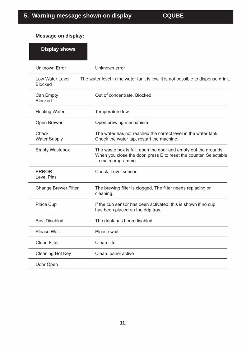
5. Warning message shown on display CQUBE
Message on display:
Display shows
Hardware Error: Hardware error Not available Drink cannot be selected as pot. Heating Water Low temperature in the water tank, the machine is heating up (blocked) Please Wait... Low Water Level Low water level in water tank. Press Enter Key Filling Water The machine is fi lling water. Please wait Select Product Temp: Strength: Jug Beverage Jug Mode Cups: Energy save mode Energy-saving mode Can Empty Concentrate is empty Warning The temperature is low, it is still possible to dispense drink. Low Temperature Low Temperature The temperature is low, the machine is blocked. Blocked
Empty Drip Tray The drip tray is full of water Overcurrent Water Level
11.
Message on display:
Display shows
Unknown Error Unknown error
Low Water Level The water level in the water tank is low, it is not possible to dispense drink. Blocked Can Empty Out of concentrate, Blocked Blocked Heating Water Temperature low Open Brewer Open brewing mechanism
Check The water has not reached the correct level in the water tank. Water Supply Check the water tap, restart the machine. Empty Wastebox The waste box is full, open the door and empty out the grounds. When you close the door, press E to reset the counter. Selectable in main programme. ERROR Check, Level sensor. Level Pins Change Brewer Filter The brewing fi lter is clogged. The fi lter needs replacing or cleaning. Place Cup If the cup sensor has been activated, this is shown if no cup has been placed on the drip tray. Bev. Disabled The drink has been disabled. Please Wait... Please wait
Clean Filter Clean fi lter
Cleaning Hot Key Clean. panel active
Door Open
5. Warning message shown on display CQUBE

12.
Message on display:
Display shows
Change The water fi lter needs replacing; press the E button to Water fi lter reset the counter.
Open Door Open door Fill clean. agent Load Detergent
Load Detergent Load clean. agent Close door Close Door
Place Jug Place pot Press Enter Enter To Start
Cleaning Brewer Clean brewer mech Time remaining Time Left
Rinsing Brewer Rinsing brewing mech Cycles left: Cycles Left
Cleaning Paused Cleaning paused Close door Close Door
Please Wait... Please wait
5. Warning message shown on display CQUBE

Error code description: Overcurrent Group 1:1 = Brewing unit (0,95A limit) Group 1:2 = Other components (Fan, Valves, Relays Etc..) (1,5A limit) Group 1:3 = Mixer 1 (3,5A limit) Group 1:5 = Mixer 2 (3,5A limit) Message is shown if one of the software fuses have been trigged. Caused by a component using too much current (A). You can run each component in the “Hardware Test” menu and the message will show when you turn on the component that is using too much current.
ERROR: Water Supply
Message will show if the inlet valve has been open for more than 3 minutes and the machine still have not acquired correct water level Action: Check that the water to the machine is turned on, Check the levelsensor, test function of the inlet valve in “Hardware Test”
ERROR: Tempsensor
Message will show if the NTC sensor is broken or is out of range of its resistance curve, also if cables have loosened from its connectors. Action: Replace NTC sensor, check cable connection on the NTC and PCB board.
ERROR: Levelpins
Message will show if the cables to the water level high & low have been connected to the wrong levelpin. Action: Swap cables to the levelsensor
ERROR: Check Heater
Message will show if the machine have not reached working temperature within 14 minutes from startup. Action: Check Overheating protection, cables to the element, solid state relay, signal from IO-board to solid state when you know the machine should heat, you can also force the element to run in “Hardware Test”.
ERROR: BREWER C.Door press E
Message will show when you interrupt a brewing cycle, eg. open the door when the machine is producing coffee. The machine needs to reach home-position before producing new drink. Action: Press E, check door sensor, brewmec sensor
Clean brewfi lter Message will show if the brewer motor uses more than 0,95A Action: Check brewfi lter if clogged, brew chamber is mounted in wrong position, brewer motor is broken.
13.
6. Error code description. CQUBE

Error code description: Peripheral Hardware Error
This message will appear if you have loaded a faulty recipe into the machine, the IO-Board is broken and does not get connection with the UcMerisc board. Usually this message appears if you eg. have loaded a standard recipe into a machine using pay system. Make sure you are using the right recipe and reload.
Memory Error: Reload Recipes
There is no recipe loaded on the UcMersic board. Transfer of the recipes have been interrupted and not completed in UcLoader. memory on the UcMersic board is broken.
Fatal Error Contact Service
Multiple Overcurrent messages at the same time, or shortcut on the IO-Board, try to run components in “Hardware Test” and locate faulty components, replace the IO-Board if no one is found.
Smartcard Error: Unknown Card
The smartcard is not programmed, chip on the smartcard is damaged, card reader is broken or broken cable between card reader and UcMerisc board.
Action: Insert and remove the card repeatedly, if the message is shown every time, try another card. If the error remains replace the card reader. Smartcard Error: Wrong Pincode
Chip on the smart card have been damaged, replace card
Pay Error Type XXX
IO-Pay board is reporting error from the payment device, check coinchanger or cashfl ow device.
14.
6. Error code description. CQUBE

15.
2
Pre brew
3
Extraction
1
Home Position
5
Emptytime
4
Decompress
Brewing cycle settings:
Aeration - Sum of sections from position 1 to 3 = 100% - Adjustment in % (0-100%), applies to sections from position 2 to 3 - Affects stirring in coffee bed > Taste: Acidity Pre brew - Pause at section between positions 1 and 3 - Adjustment (0-10 sec) at step in 0.1 sec - Affects the amount of acid from stirring> Taste: Acidity Extraction - Pause between positions 2 and 4 - Adjustment (0-20 sec) at step in 0.1 sec - Affects total contact time > Taste: Body Press time - Sum of sections from position 3 to 5 = 100% - Adjustment in % (0-100%), applies to sections from position 3 to 4 - Affects the consistency of the grounds > Cleanliness - Affects the strain on plunger and cylinder > Operating reliability: Vacuum pressure in cylinder Decompress time - Pause between positions 3 and 5 - Adjustment (0-10 sec) at step in 0.1 sec - Affects the consistency of the grounds > Cleanliness - Affects the strain on plunger and cylinder > Operating reliability: Vacuum pressure in cylinder Empty time - Pause between positions 5 and Home position - Adjustment (0-10 sec) at step in 0.1 sec - Affects the amount of fi nished coffee that comes out of the cylinder > Cleanliness / Operating reliability
After Empty time the brewing continues until the micro switch is activated - Home position
7. Brewing cycle settings CQUBE

16.
7. Brewing cycle settings CQUBE
REMEMBER
For fresh brew machines, the coffee should have the coarsenessautomatic grinding. Grinder settings for automatic grinding are: grinding blades together and set 8 steps back. The optimal total contact time between water and coffee for automatic grinding is 30 sec. The basic settings for coffee were defi ned in cooperation with ECBC in Oslo, to ensure quality in the cup.
Water amount 170 ml (before contact with coffee) Coffee amount 11 g (requires above grinder settings) Aeration 70% Pre brew 3.8 sec Extraction time 11.5 sec Press time 50% Decompress time 2.0 sec Empty time 6.0 sec
TIPS
To compensate for lower Aeration (higher %) Pre brew can be increased to a certain degree. Increased Pre brew time means that more water and coffee are added before the plunger reaches the top position. This produces a better blend.
Adjust Pre brew in steps of 0.1 - 0.2 sec at a time; this quickly provides results in terms of taste.¤ Varies for different coffee types, however.
Increased Extraction time produces more body, but only to a certain degree. Too much time makes the coffee over-extracted, which produces a very bitter taste.
To little Extraction time means the coffee is under-extracted, leaving little aftertaste.
If you wish to cut down on the total brewing cycle time, you want the taste to undergo minimal change. If you shorten the Extraction time, you can compensate somewhat by either putting the grinder on a fi ner coarseness setting or increasing the coffee dose. You then have to test the coffee carefully, to make sure it is not too strong. When you have tasted several cups of coffee, it is very easy to misjudge the taste. For increased dose, the taste is very accurate when you swallow, but the aftertaste disappears and instead it is harsh on the throat.
If you increase the volume too much, the grounds can become soaked. To fi x this, you must increase the Press time. This causes the plunger to lower more before the pause (position 3-4); the result is a higher vacuum effect in the cylinder and more fi nished coffee is sucked out through grounds. At the same time, you should increase the Decompress time, to allow the coffee to penetrate the fi lter before empty position is reached and the vacuum pressure in the cylinder is released. Remember to increase the Empty time so all the coffee can drain out of the cylinder.

17.
7. Brewing cycle settings CQUBE
S
YMPT
OM
C
AU
SE
S
OLU
TIO
NTh
e w
ater
and
cof
fee
spla
sh o
ut
of th
e br
ewin
g ch
ambe
r dur
ing
the
aera
tion
proc
ess.
- Har
d w
ater
. A h
igh
surfa
ce te
nsio
n m
akes
it
diffi
cult
for t
he c
offe
e to
abs
orb
wat
er.
- Ver
y fre
sh c
offe
e of
ten
take
s a
little
long
er
to a
bsor
b w
ater
- Run
the
clea
ning
pro
gram
me
and
repl
ace
the fi l
ter i
f nec
essa
ry.
- Low
er th
e A
erat
ion
%. T
est a
cup
. In
crea
se th
e P
re b
rew
to c
ompe
nsat
e if
nece
ssar
y.Th
e co
ffee
eith
er la
cks
or h
as
too
muc
h ch
arac
ter.
- The
aci
dity
set
ting
is to
o lo
w/h
igh.
- The
cof
fee
is to
o ol
d.- R
un th
e cl
eani
ng p
rogr
amm
e an
d re
plac
e th
e fi l
ter i
f nec
essa
ry.
- Inc
reas
e th
e P
re b
rew
set
ting
if th
e co
ffee
lack
s ch
arac
ter/a
cidi
ty. 0
.1 -
0.2
sec
mak
es a
ver
y bi
g di
ffere
nce.
- Low
er th
e P
re b
rew
set
ting
for t
he o
p-po
site
effe
ct.
- Em
pty
the
cani
ster
and
grin
der,
clea
n an
d refi l
l cof
fee.
The
grou
nds
are
very
sog
gy o
r al
mos
t wat
ery
whe
n th
e br
ewer
op
ens.
- The
fi lte
r is
clog
ged.
- The
wat
er is
har
d. A
hig
h su
rface
tens
ion
mak
es it
diffi
cul
t for
the
coffe
e to
abs
orb
wat
er a
nd fo
r the
wat
er to
pas
s th
roug
h th
e fi l
ter.
- Ver
y fre
sh c
offe
e of
ten
take
s a
little
long
er
to a
bsor
b w
ater
- The
coa
rsen
ess
setti
ng is
too fi n
e.- C
offe
e do
se is
too
high
.- T
he v
olum
e se
tting
is to
o hi
gh.
- The
bre
win
g ch
ambe
r may
be
crac
ked.
- The
cyl
inde
r may
be
crac
ked.
- Run
the
clea
ning
pro
gram
me
and
repl
ace
the fi l
ter i
f nec
essa
ry.
- Inc
reas
e th
e ex
tract
ion
time
if ne
ces-
sary
.- I
ncre
ase
the
Pre
ss ti
me
and/
or D
e-co
mpr
ess
time
if ne
cess
ary.
- Che
ck g
rinde
r set
ting
/cle
an.
- Che
ck th
e S
treng
th s
ettin
g.- C
heck
the
Volu
me
setti
ng.
- Ins
pect
the
brew
ing
cham
ber f
or
crac
ks.
- Ins
pect
the
cylin
der f
or c
rack
s.Th
e br
ewin
g m
echa
nism
sou
nds
very
stra
ined
.- T
he fi
lter i
s cl
ogge
d- T
he c
oars
enes
s se
tting
is to
o fi n
e.- T
he c
offe
e do
se is
too
high
.- T
he b
rew
ing
mec
hani
sm s
ettin
g ne
eds
adju
stm
ent.
- Run
the
clea
ning
pro
gram
me
and
repl
ace
the fi l
ter i
f nec
essa
ry.
- Che
ck g
rinde
r set
ting
/cle
an.
- Che
ck th
e S
treng
th s
ettin
g.- R
emov
e th
e br
ewin
g m
echa
nism
, ro
tate
, adj
ust a
ccor
ding
to th
e m
anua
l in
stru
ctio
ns.
The
grou
nds
scra
per c
anno
t re
mov
e al
l the
gro
unds
.- T
he b
rew
ing
mec
hani
sm s
ettin
g ne
eds
adju
stm
ent.
- The
gro
unds
scr
aper
is d
amag
ed.
- Rem
ove
the
brew
ing
mec
hani
sm,
rota
te, a
djus
t acc
ordi
ng to
the
man
ual
inst
ruct
ions
.- R
epla
ce th
e gr
ound
s sc
rape
r.Th
e gr
ound
s sc
rape
r is
still
on
one
side
of t
he b
rew
ing
cham
-be
r dur
ing
the
brew
ing
cycl
e.
- The
bre
win
g ch
ambe
r is
inco
rrec
tly in
-st
alle
d.- R
emov
e th
e br
ewin
g m
echa
nism
, ro-
tate
unt
il it
open
s, p
ull o
ut a
nd in
sert
the
brew
ing
cham
ber.
Che
ck th
at it
follo
ws
the
cycl
e.
SYMPTOM - CAUSE - SOLUTION

18.
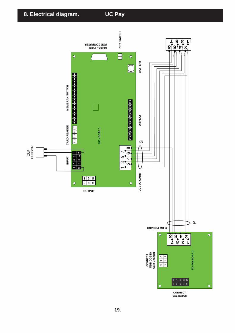
8. Electrical diagram. CQUBE
19.
8. Electrical diagram. UC Pay

20.
8. Electrical diagram. High Power Connection

9. Exploded view. Door / Front CQUBE
21.
9 10
1
2
6
3 4
7
8 11
13
12
5
20
19
18
15
14
17
21
22
16

Description; Art. no. Pos. no. Amount/unit
Valid for page 21 Door / Front
Bean container window (high) 1105530 1 1Bean container window (low) 1105531 2 1Top Lid 1105533 3 1Frame for card reader 1505035 4 1Card Reader 1602697 5 1Slide latch 1202495 6 3Chrome ring 1105532 7 2Outlet drip tray 1105534 8 2Drip tray 1105528 9 1Drip tray insert 1102035 10 1Drip tray extension 1105529 11 1Spiral 120229 12 2Cup stand 1102036 13 1Light emitting diode white 1608708 14 1Light emitting diode red 1608710 15 1Cup sensor 7140011 16 1Outlet angled 1201415 17 1Display 1604122 18 1Lock with nut 120253 19 1Fastener for circuit board 1203416 20 4User Card (green 1602692 21 1Technical Service 1602693 22 1
22.
10. Spare parts list. CQUBE

9. Exploded view. Machine CQUBE
23.
1
8
18
2
6
13
15
16
17
7
5
4
3
14
19
21
22
23
20
24
12
Säkring 5 AT
25
11
26

Description; Art. no. Pos. no. Amount/unit
Valid for page 23 MachineBrew mechanism 710075 1 1 Electronic card IO - TE 1604111 2 1 Fuse 5A T 1604384 -- 3Power supply 150W 1031652 3 1Front, bean container high 1105498 4 1Front, bean container low 1105499 5 1Centrifugal Fan, 24V 0,24A 1604151 6 1Lid bean container 1105497 7 1Frame for lid, bean container 1105496 8 1
Grinder 1604752 11 1 Relay 1pol 160243 12 1 Socket 160246 12 1 Capacitor 12 μF 832392 12 1Main socket 160570 13 1Power cord Europe 160565 14 1Valve double 2,5L/min. 1206281 15 1Centrifugal Fan, 24V 0,18A 1604152 16 1Connector 160549 17 1Waste box 1105359 18 1Switch 2 pol. 160801-04 19 1Inlet hose 150541 20 1Micro switch 710070 21 1Waste funnel 1105357 22 1Waste box base cabinet 1105317 23 1Solid state 1604201 24 1Lock complete (door) 120253 25 1Key, (door) 1202531 26 2
Options:Water fi lter + patron complete. 1505360 - 1Filter head 1505362 - 1Filter cartridge 1505361 - 1
24.
10. Spare parts list. CQUBE

25.
9. Exploded view. Tank CQUBE
9
10
6
7
12
16
13
5
18 17
15
11 8
2
14
19
3
4
20
1

Description; Art. no. Pos. no. Amount/unit
Valid for page 25 TankTank complete 7140019 1 1Water tank 5L + lid 260141 2 1Insulation for refrigeration unit 1201292 3 1Insulation bottom 120131 4 1Outlet valve 24V 1206289 5 1Seal for outlet valve 1561010 6 1Element 2200W 1601311 7 1Gasket water tank 1561012 8 1Double seal level sensor 1605362 9 1Sensor pin, short 1205302 10 1Sensor pin, long 1205301 11 1Steam hose 1561015 12 1NTC compl. belong 711000 13 1Seal for NTC thermistor 1605361 14 1Drainage tube 1561007 15 1Inlet hose 1561014 16 1Motoraxle for motor gear 1604614 17 3Motor gear, without axle 1604612 18 3High limit control 220220 19 1Silicone hose (sales by metre) 150501 20 -
26.
10. Spare parts list. CQUBE

27.
9. Exploded view. Mixing system CQUBE
1
4
3
1
2
5 6 7
9
1
8
13
10 11 12
14
14
silicone hose sales by metre

28.
10. Spare parts list. CQUBE
Description; Art. no. Pos. no. Amount/unit
Valid for page 27 Mixing systemHose adaptor, mixing system 1604836 1 5Outlet brew mechanism 1201416 2 1Outlet brew mechanism, extension 1201417 3 1Outlet angled 1201415 4 3Hose brew mechanism - fan 1505034 5 1Hose mixing bowl - fan 1505033 6 1Valve double outlet, CO2 1104525 7 1Valve double outlet, cold water 1104534 8 1Brewing motor complete 1201432 9 1Brewer dock white 120144 10 1Pin 3,5x36 1201453 11 1Pin 2,0x36 1201454 12 1Micro switch V5J (FB brew engine) 160829 13 1Silicone hose (sales by metre) 150501 14 -

29.
3
2
11
7 6 4 5
1
10 9 8
9. Exploded view. Mixing bowl CQUBE
12
silicone hose sales by metre

30.
10. Spare parts list. CQUBE
Description; Art. no. Pos. no. Amount/unit
Valid for page 29 Mixing bowlAngle for mixing bowl 1206705 1 2Mixing bowl 1206704 2 2Steam trap 1206707 3 2Bulkhead adaptor 1206706 4 2O-ring 120638 5 2Motor whipper plate 1604592 6 2
Whipper motor 24V Complete 7001111 7 2 (incl. slinger disc, motor whipper plate)
Slinger disc 1604804 8 2Mounting plate 1206702 9 2Grommet for whipper pin 120655-02 10 2Whipper 1206703 11 2Silicone hose (sales by metre) 150501 12 -

1
2
3
4
5
6
7
8
9
6
10
8
11
12
13
15
16
17
18
19
water + CO2
14
31.
9. Exploded view. Water + CO2 CQUBE
Description; Art. no. Pos. no. Amount/unit
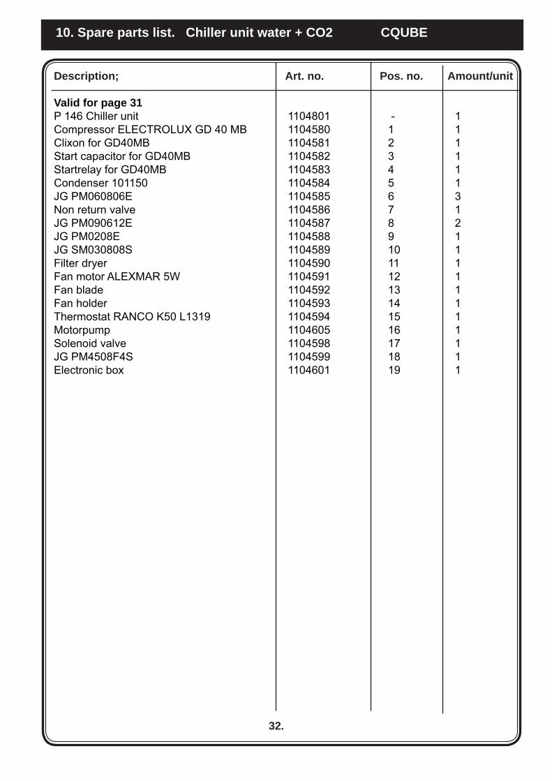
Valid for page 31P 146 Chiller unit 1104801 - 1Compressor ELECTROLUX GD 40 MB 1104580 1 1Clixon for GD40MB 1104581 2 1Start capacitor for GD40MB 1104582 3 1Startrelay for GD40MB 1104583 4 1Condenser 101150 1104584 5 1JG PM060806E 1104585 6 3Non return valve 1104586 7 1JG PM090612E 1104587 8 2JG PM0208E 1104588 9 1JG SM030808S 1104589 10 1Filter dryer 1104590 11 1Fan motor ALEXMAR 5W 1104591 12 1Fan blade 1104592 13 1Fan holder 1104593 14 1Thermostat RANCO K50 L1319 1104594 15 1Motorpump 1104605 16 1Solenoid valve 1104598 17 1JG PM4508F4S 1104599 18 1Electronic box 1104601 19 1
32.
10. Spare parts list. Chiller unit water + CO2 CQUBE

2
10
1
4
3
6
8
5
7
9
33.
9. Exploded view. Chiller unit in machine CQUBE
Chiller unit, water
Description; Art. no. Pos. no. Amount/unit
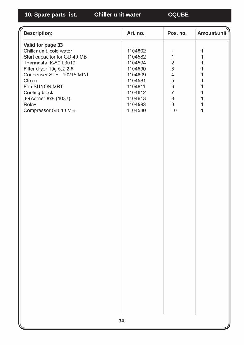
Valid for page 33Chiller unit, cold water 1104802 - 1Start capacitor for GD 40 MB 1104582 1 1Thermostat K-50 L3019 1104594 2 1Filter dryer 10g 6,2-2,5 1104590 3 1Condenser STFT 10215 MINI 1104609 4 1Clixon 1104581 5 1Fan SUNON MBT 1104611 6 1Cooling block 1104612 7 1JG corner 8x8 (1037) 1104613 8 1Relay 1104583 9 1Compressor GD 40 MB 1104580 10 1
34.
10. Spare parts list. Chiller unit water CQUBE

24
910
1716
15
1813
1412
118
1
73
64
52
20 22
19
21
23
35.
9. Exploded view. Grinder EK21 CQUBE
Description; Art. no. Pos. no. Amount/unit
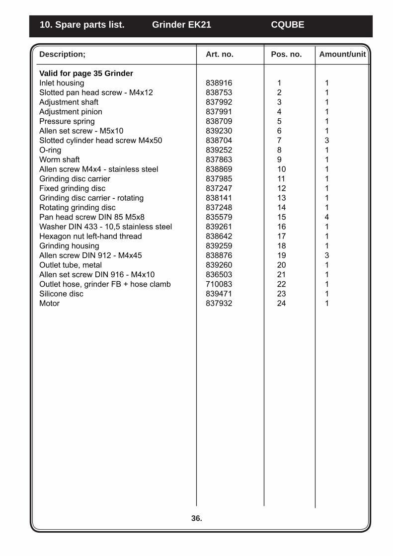
Valid for page 35 GrinderInlet housing 838916 1 1Slotted pan head screw - M4x12 838753 2 1Adjustment shaft 837992 3 1Adjustment pinion 837991 4 1Pressure spring 838709 5 1Allen set screw - M5x10 839230 6 1Slotted cylinder head screw M4x50 838704 7 3O-ring 839252 8 1Worm shaft 837863 9 1Allen screw M4x4 - stainless steel 838869 10 1Grinding disc carrier 837985 11 1Fixed grinding disc 837247 12 1Grinding disc carrier - rotating 838141 13 1Rotating grinding disc 837248 14 1Pan head screw DIN 85 M5x8 835579 15 4Washer DIN 433 - 10,5 stainless steel 839261 16 1Hexagon nut left-hand thread 838642 17 1Grinding housing 839259 18 1Allen screw DIN 912 - M4x45 838876 19 3Outlet tube, metal 839260 20 1Allen set screw DIN 916 - M4x10 836503 21 1Outlet hose, grinder FB + hose clamb 710083 22 1Silicone disc 839471 23 1Motor 837932 24 1
36.
10. Spare parts list. Grinder EK21 CQUBE
21
7
345
6
11
14
9
12
10
13
15
16
201817 19
8
37.
9. Exploded view. Brewing mechanism CQUBE

3536
38
40
37333429 30
2831
39
2122232426 25
4243
32
41
27
38.
9. Exploded view. Brewing mechanism CQUBE

Description; Art. no. Pos. no. Amount/unit
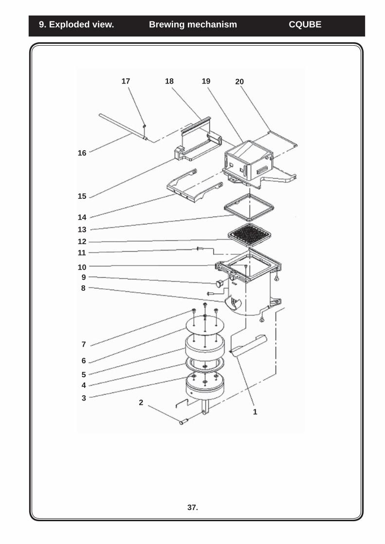
Valid for page 37 brew mechanismDefl ector, Cylinder 4720008 1Pin, Crank Arm 4720010 2O-ring piston 4720012 3Rubber ring piston 4720013 4Tefl on seal 4720014 5Plate, Top 4720015 6Screw, 8 x 1/2, Truss 4720016 7Cylinder 4720017 8Plug, vent, Cylinder 4720018 9Screw, 4-40 x ¼, 4720019 10Screw, 8-32 x ½, 4720020 11Assembly Filter 47200213 12Seal, Brew Chamber 4720022 13Bar, Latch 4720023 14Carriage, Wiper 4720024 15Rod, Carriage, Wiper 4720025 16Retaining Ring, .250 4720026 17Wiper, Complete 4720027 18Brew Chamber 4720028 19Spring Clip, Latch Bar 4720029 20
Valid for page 38 brew mechanismHousing, Vertical Rod 4720001 21Cam, Triple 4720002 22Unwipe Arm Assembly 4720003 23Spacer, Wipe Arm 4720004 24Spring, Wipe Arm 4720005 25Retaining Ring,TRU ARC 4720006 26Vevarm 4720007 27Plate, Ret., Cycle 4720030 28Plate, Ret., Support 4720031 29Latch, Block, LHS 4720032 30Latch, Block, RHS 4720033 31Retaining Ring 4720034 32Tube, Outlet, Water 4720035 33Wrap, Brew Chamber 4720036 34Shim 0,2 1303501 35Shim 0,5 1303502 36Spacer, Sil., 3/16 x .350 x 1.5 4720038 37Spring, H-Frame 4720039 38H-Frame 4720040 39Screw, 8-32 x 3/4, PAN 4720041 40Pin, Grooved, 3/16 x 1.25 4720046 41Wipe Arm, Assembly 4720048 42Vertical Rod, Welded 4720049 43
39.
10. Spare parts list. Brewing mechanism CQUBE
40.
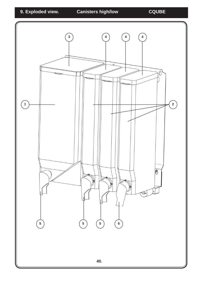
9. Exploded view. Canisters high/low CQUBE
3 4 4 4
5 5 6 5
1 2

Description; Art. no. Pos. no. Amount/unit
Valid for page 40
Canister high 160 x 400 1204964 1 1Canister high 67 x 400 1204965 2 3Lid for 160 canister 1204952 3 1Lid for 67 canister 1204953 4 3Concentrate pipe left 120489 5 3Concentrate pipe right 120493 6 1
Canister low 160 x 400 1204887 1 1Canister low 67 x 250 1204962 2 3Lid for 160 canister 1204952 3 1Lid for 67 canister 1204953 4 3Concentrate pipe left 120489 5 3Concentrate pipe right 120493 6 1
41.
10. Spare parts list. high/low CQUBE

42.
9. Exploded view. Bean container/ canisters high/low CQUBE
1 2 2 2
4 4 5
3

Description; Art. no. Pos. no. Amount/unit
Valid for page 42
Bean container high 1105494 1 1Canister high 67 x 400 1204965 2 3Lid for 67 canister 1204953 3 3Concentrate pipe left 120489 4 2Concentrate pipe right 120493 5 1
Bean container low 1105495 1 1Canister low 67 x 250 1204962 2 3Lid for 67 canister 1204953 3 3Concentrate pipe left 120489 4 2Concentrate pipe right 120493 5 1
43.
10. Spare parts list Bean container/ canisters high/low CQUBE

Model CQUBE M CQUBE L
A 879 mm 995 mmB 420 mm 420 mmC 565 mm 565 mm
11. Dimension sketch. CQUBE
44.

45.
12. Overview of components Cold Water CQUBE
Water IN Water OUT Thermostat
Condenser Dryer
Fan Compressor Cooling block

Carbon dioxidetube
Gas holder
46.
12. Overview of components Water + CO2 CQUBE
Electronic box
Fan
Condenser
Compressor
Dryer
Water IN
CoolingblockCarbonatedwater OUT
Carbon acid IN
Water OUT
Solenoid valve
Pump pressure increase
Thermostat

47.
13. Service intervals. CQUBE

...............................................................................
...............................................................................
...............................................................................
Your dealer
Art. nr/Art. no. 1740067
FOR SERVICEPlease contact
CREM International ABBox 10, Viksgränd 2, SE-670 40 Åmotfors, Sweden
Tel: +46 (0)570-477 00, Fax: +46 (0)570-47719E-mail: [email protected] www.creminternational.com