Embed Size (px)
Citation preview
AD-A257 379
WEAPON SYSTEM EXPLOSIVES SAFETYREVIEW BOARD
TECHNICAL MANUAL FORELECTRONIC SAFETY AND ARMINGDEVICES WITH NON-INTERRUPTED
EXPLOSIVE TRAINS
DTICF_] CI.,EC fNOV 02 1992
S~E
30 Sept 1990
A p() w f cr M"'I*J_ (Jr r jH
F92 28546
WSESRB Technical Manual forElectronic Safety and Arming Deviceswith Non-Interrupted Explosive Trains
Forward
1. Munition fuzes historically have utilized sensitive explosive ele-ments whose output has been physically interrupted until arming. Con-trol of the arming process in these fuzes was accomplished by mechanicalmeans. The advent and rapid advancement in solid state electronics hasfurnished alternatives for fuze safety design. In recent years, ad-vances in explosive initiation elements have provided an option foreliminating the need for physical interruption of the explosive train.The application of these technological advances is addressed in thismanual.
2. This Technical Manual is for use in the design of fuzes and otherinitiating systems to be used by the United States Navy as a supplemertto the requirements of MIL-STD-1316.
3. Beneficial comments (recommendations, additions, deletions) and anypertinent data which may be of use in improving this document shall beaddressed to:
ChairmanWeapon System Explosives Safety Review Bo&rdNaval Sea Systems CommandWashington, DC 20362.
Comments should be forwarded through the appropriate Systems Command foreach project.
4. This manual extends specific design safety criteria for fuzes andother initiating systems beyond that covered by MIL-STD-1316 and specif-ically applies to the safe and arm functions used in weapon systemswhich have in-line explosive or initiator trains. This manual providesadditional design criteria for fuzes and safety and arming devices (withnon-interrupted explosive trains) that do not fully meet the require-ments of MIL-STD-1316C. Although it repeats some information from MIL-STD-1316, it does not supersede these requirements for systems that com-ply with the requirement for non-interrupted excplosive trains with twophysical locks.
5. The safe and arm requirements specified herein are mandatory funda-mental elements of design, engineering, production, and procurement.Fuzes and initiating systems shall provide safety that is consistentwith mission requirements throughout the assembly, handling, storage,transportation, use, and disposal phases of the system life cycle.
WSESRB Technical Manual forElectronic Safety and Arming Devices
with Non-Interrupted Explosive Trains
Table of Contents
Forward 1
Table of Contents ii
1. SCOPE 11.1 Purpose 11.2 Scope of Applicability 1
1.3 Excluded munitions 1
2. APPLICABLE DOCUMENTS 22.1 Government Documents 2
2.1.1 Specifications, Standards and Handbooks 22.1.2 Other Government Documents 3
3. DEFIbITIONS 43.1 General 4
3.1.1 Arm 43.1.2 Arm-Fire Devices 43.1.3 Arming delay 43.1.4 Assembled fuize or initiating system 43.1.5 Booster and lead explosives 43.1.6 Credible environments 43.1.7 Dud 43.1.8 Dynadaic electrical safety feature 43.1.9 Early-function 43.1.10 Electronic Safety and Arming Devices 53.1.11 Enabling 53.1.12 Environment 53.1.13 Environmental stimulus 53.1.14 Explosive Ordnance Disposal 53.1.15 Explosive train 53.1.16 Fail-safe design 53.1.17 Firmware 52.1.18 Function 53.1.19 Fuze or Initiating System 53.1.20 Fuze or initiating systelt installation 53.1.21 Hand Grenades 53.1.22 Handheld Ordnance Devices 63.1.23 Independent safety feature 63.1.24 Initiator 63.1.25 Interrurted explosive train 63.1.26 Launch cycle 63.1.27 Main charge 63.14.28 Manual arming feature 63.1.29 Manually Emplaced Ordnance Items 63.1.30 maximum Allowable Safe Stimulus 6
ii
3.1.31 Mechanical safety feature 63.1.33 Non-interrupted explosive train 63.1.34 Premature function 63.1.35 Primary explosives 63.1.36 Pyrotechnic train 7?.1.37 Safe Condition 73.1.39 Safety and Arming Device 73.1.40 Safety feature 73.1.41 Safety Interlock 73.1.42 Satety system 73.1.43 Safety system failure 73.1.44 Sensor, environmental 73.1.45 Sterilization 7
4. GENERAL REQUIREMENTS 84.1 General 8
4.1.1 Compatibility 84.2 ESAD Safety Systems 8
4.2.1 Safety redundancy. 84.2.1.1 Enabling environments 84.2.1.2 Dynamic electrical safety feature(s, 94.2.1.3 Launch environments 94,2.1.4 Physical partitioning 94.2.1.5 Manual Arming Features 94.2.1.6 Safety feature type combinations 94.2.1.7 Safety Interlocks 10
4.2.2 Arming delay 104.2.2.1 Safe Separation Safety 104.2.2.2 Timers 104.2,2.3 Post-safe separation safety 10
4.2.3 Manual arming 104.2.4 Logic functions 114.2.5 Firmware 114.2.6 Application Specific Integrated Circuits 11
4.2.6.1 ASIC Design 114.2.6.2 ASIC Testing 11
4.3 Safety system failure rate 114.3.1 Analyses 11
4.4 Design for quality control 124.5 Design approval 4 124.6 Design features 13
4.6.1 Stored energy 134.6.1.1 Lithium Batteries 13
4.6.2 Explosive ordnance disposal (EOD) 134.6.2.1 EOD Design Features 134.6.2.2 EOD reviewing authority 13
4.6.3 Safe condition 144.6.3.1 Safe condition assurance options 144.6.3.2 Visual indication 14
4.6.4 Firing Stimulus Dissipation 154.7 Electromagnetic ana electrical hazards 15
4.7.1 Electromagnetic radiation (EMR) 154.7.2 Electrostatic Discharge (ESD) 154.7.3 Electromagnetic pulse (EMP) 15
iii
4.7.4 Lightning effects 154.7.5 Power Supply Transients 15
4.8 Reviewing authority 16
5. DETAILED REQUIREMENTS 175.1 General 175.2 Explosive trains 17
5.2.1 Maximum acceptable safe stimulus (MASS) 175.2.2 Explosive sensitivity 175.2.3 Explosive train interruption 175.2.4 Non-interrupted explosive train control 18
5.2.4.1 Function energy control 185,,2.4.2 Electrical Initiator Sensitivity 18
5.3 Design features 195.3.1 Sterilization/Disable/Self-destruct 19
5.3.1.1 Sterilization of torpedoes 195.3.2 Fail-safe design 19
6. NOTES 206.1: Intended use 206.2 Safety Review 206.3 Custodian of Navy approvals 206.4 Subject term (key word) listing 20
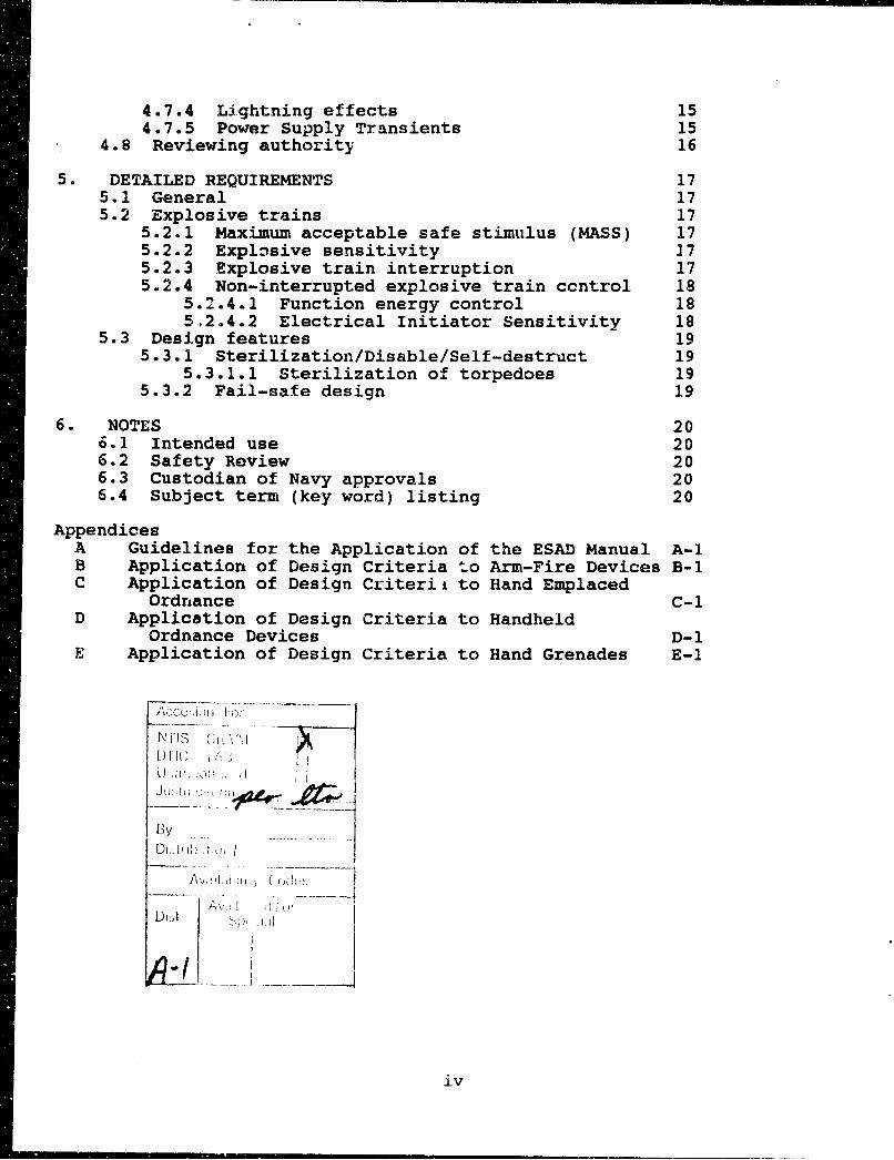
AppendicesA Guidelines for the Application of the ESAD Manual A-iB Application of Design Criteria to Arm-Fire Devices B-iC Application of Design Criteria to Hand Emplaced
Ordnance C-iD Application of Design Criteria to Handheld
Ordnance Devices D-1E Application of Design Criteria to Hand Grenades E-1
1) -11 C ,"1 ;D I ,, VLJI ,iv
Dy- 1D~i:A h i>, i
iv
WSESRB Technical Manual forElectronic Safety and Arming Devices
with Non-Interrupted Explosive Trains
1. SCOPE
1.1 Purpose
MIL-STD-1316 establishes design safety criteria for fuzes andSafety and Arming (S&A) devices that are subsystems of fuzes. This doc-ument supplements MIL-STD-1316 by providing additional safety designcriteria for electronically controlled fuzes, S&As, and initiation sys-tems. Hereinafter, these fuzes and S&As are referred to as ElectronicSafety and Arming Devices (ESADs).
1.2 Scope of Applicability
This document applies to the design of ESADs having electronic orpartly electronic means of arming and firing and not having interruptedexplosive trains. It applies to all ordnance used or transported by theNavy. Within the scope of this document, ESADs include items commonlyreferred to as fuzes, safety and arming devices (S&As or SADs), arm firedevices (AFDs), ignitions safety devices (ISDs), etc. This document ap-plies to the design of electronic Arm-Fire Devices (AFDs), hand emplacedordnance, and other items to the extent specified in the Appendices.
1.3 Excluded munitions
This standard does not apply to fuzes and S&A devices for Nuclearwarheads.
2. APPLICABLE DOCUMENTS
-2.1 Government Documents
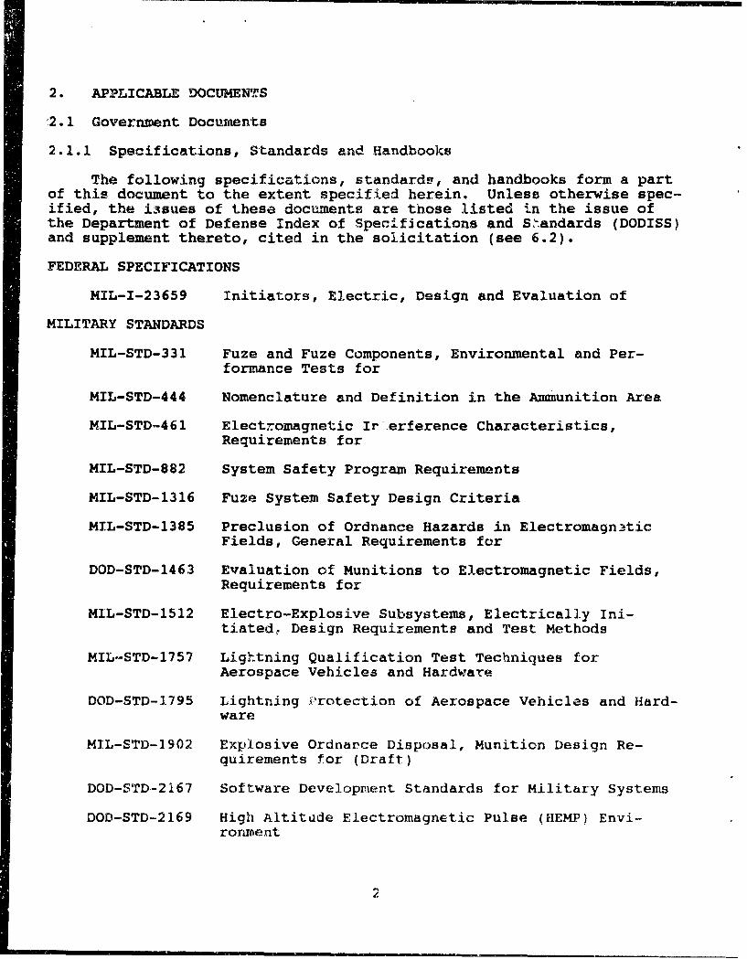
2.1.1 Specifications, Standards and Handbooks
The following specifications, standards, and handbooks form a partof this document to the extent specified herein. Unless otherwise spec-ified, the i3sues of these documents are those listed in the issue ofthe Department of Defense Index of Specifications and Shandards (DODISS)and supplement thereto, cited in the solicitation (see 6.2).
FEDERAL SPECIFICATIONS
MIL-I-23659 Initiators, Electric, Design and Evaluation of
MILITARY STANDARDS
MIL-STD-331 Fuze and Fuze Components, Environmental and Per-formance Tests for
MIL-STD-444 Nomenclature and Definition in the Ammunition Area
MIL-STD-461 Electromagnetic Irerference Characteristics,Requirements for
MIL-STD-882 System Safety Program Requirements
MIL-STD-1316 Fuze System Safety Design Criteria
MIL-STD-1385 Preclusion of Ordnance Hazards in ElectromagnaticFields, General Requirements for
DOD-STD-1463 Evaluation of Munitions to Electromagnetic Fields,Requirements for
MIL-STD-1512 Electro-Explosive Subsystems, Electrically Ini-tiated, Design Requirements and Test Methods
MIL-STD-1757 Lightning Qualification Test Techniques forAerospace Vehicles and Hardware
DOD-STD-1795 Lightning Protection of Aerospace Vehicles and Hard-ware
MIL-STD-1902 Explosive Ordnance Disposal, Munition Design Re-quirements for (Draft)
DOD-STD-2167 Software Development Standards for Military Systems
DOD-STD-2169 High Altitude Electromagnetic Pulse (HEMP) Envi-ronment
2
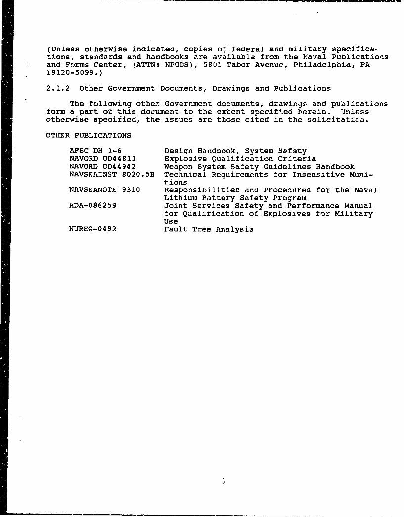
(Unless otherwise indicated, copies of federal and military specifica-tions, standards and handbooks are available from the Naval Publicationsand Forms Center, (ATTN: NPODS), 5801 Tabor Avenue, Philadelphia, PA19120-5099.)
2.1.2 Other Government Documents, Drawings and Publications
The following other Government documents, drawings and publicationsform a part of this document to the extent specified herain. Unlessotherwise specified, the issues are those cited in the solicitation.
OTHER PUBLICATIONS
AFSC DH 1-6 Desiqn Handbook, System SafetyNAVORD OD44811 Explosive Qualification CriteriaNAVORD OD44942 Weapon System Safety Guidelines HandbookNAVSEAINST 8020.5B Technical Requirements for Insensitive Muni-
tionsNAVSEANOTE 9310 Responsibilities and Procedures for the Naval
Lithium Battery Safety ProgramADA-086259 Joint Services Safety and Performance Manual
for Qualification of Explosives for MilitaryUse
NUREG-0492 Fault Tree Analysi3
3
3. DEFINITIONS
-3.1 General
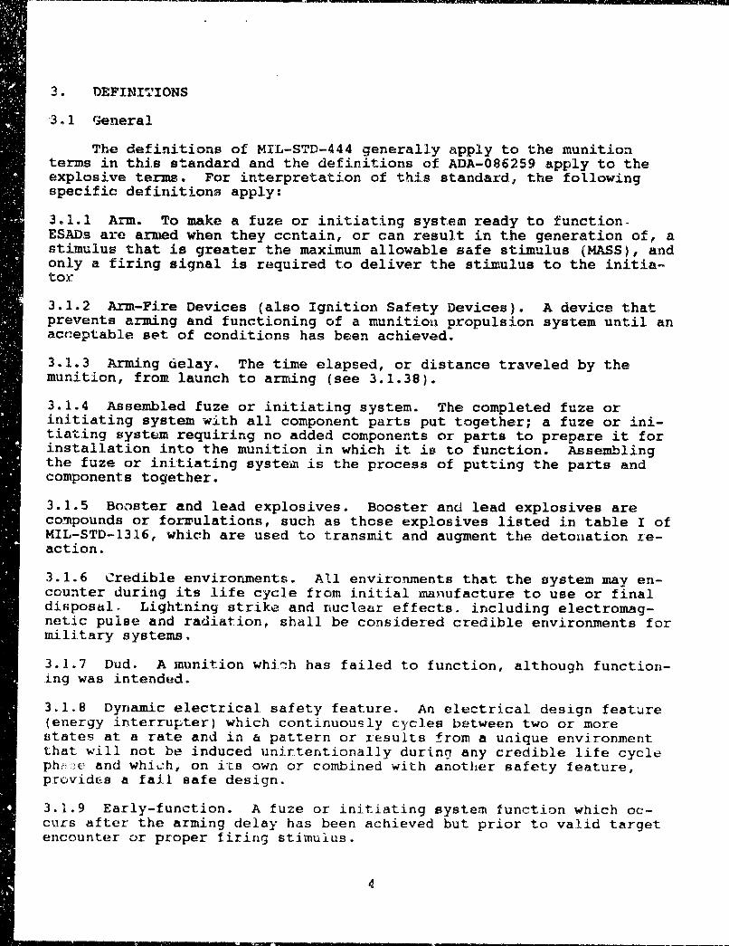
The definitions of MIL-STD-444 generally apply to the munitionterms in this standard and the definitions of ADA-086259 apply to theexplosive terms. For interpretation of this standard, the followingspecific definitions apply:
3.1.1 Arm. To make a fuze or initiating system ready to function.ESADs are armed when they ccntain, or can result in the generation of, astimulus that is greater the maximum allowable safe stimulus (MASS), andonly a firing signal is required to deliver the stimulus to the initia-tor
3.1.2 Arm-Fire Devices (also Ignition Safety Devices). A device thatprevents arming and functioning of a munition propulsion system until anacceptable set of conditions has been achieved.
3.1.3 Arming delay. The time elapsed, or distance traveled by themunition, from launch to arming (see 3.1.38).
3.1.4 Assembled fuze or initiating system. The completed fuze orinitiating system with all component parts put together; a fuze or ini-tiating system requiring no added components or parts to prepare it forinstallation into the munition in which it is to function. Assemblingthe fuze or initiating system is the process of putting the parts andcomponents together.
3.1.5 Booster and lead explosives. Booster and lead explosives arecompounds or forwulations, such as those explosives listed in table I ofMIL-STD-1316, which are used to transmit and augment the detonation re-action.
3.1.6 Credible environments. All environments that the system may en-counter during its life cycle from initial manufacture to use or finaldisposal. Lightning strike and nuclear effects, including electromag-netic pulse and radiation, shall be considered credible environments formilitary systems.
3.1.7 Dud. A munition whi'7h has failed to function, although function-ing was intended.
3.1.8 Dynamic electrical safety feature. An electrical design feature(energy interrupter) which continuously cycles between two or morestates at a rate and in a pattern or results from a unique environmentthat will not be induced unirterntionally during any credible life cycleph,• :e and which, on itLs own or combined with another safety feature,provides a fail safe design.
3.1.9 Early-function. A fuze or initiating system function which oc-curs after the arming delay has been achieved but prior to valid targetencounter or proper firing stimulus.
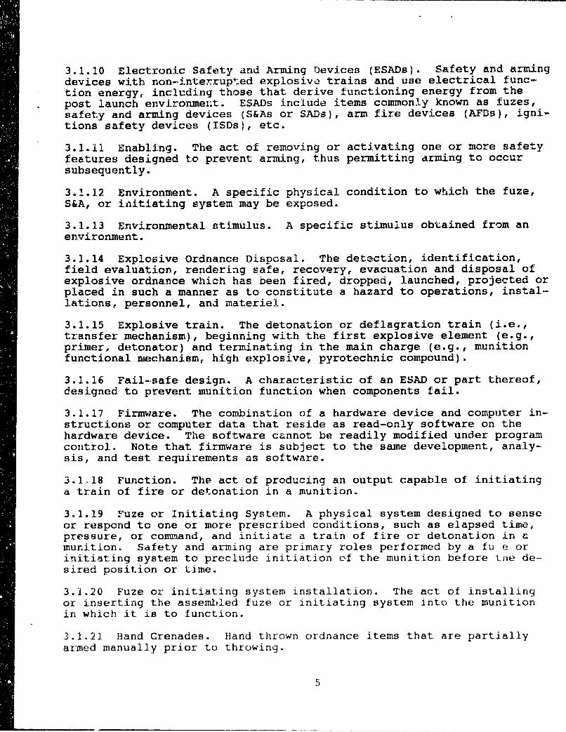
3.1.10 Electronic Safety and Arming Devices (ESADs). Safety and armingdevices with non-jinterrupted explosive trains and use electrical func-tion energy, including those that derive functioning energy from thepost launch environmeiit. ESADs include items commonly known as fuzes,safety and arming devices (S&As or SADs), arm fire devices (AFDs), igni-tions safety devices (ISDs), etc.
3.1.11 Enabling. The act of removing or activating one or more safetyfeatures designed to prevent arming, thus permitting arming to occursubsequently.
3.1.12 Environment. A specific physical condition to which the fuze,S&A, or initiating system may be exposed.
3.1.13 Environmental stimulus. A specific stimulus obtained from anenvironment.
3.1.14 Explosive Ordnance Disposal. The detection, identification,field evaluation, rendering safe, recovery, evacuation and disposal ofexplosive ordnance which has been fired, dropped, launched, projected orplaced in such a manner as to constitute a hazard to operations, instal-lations, personnel, and materiel.
3.1.15 Explosive train. The detonation or deflagration train (i.e.,transfer mechanism), beginning with the first explosive element (e.g.,primer, detonator) and terminating in the main charge (e.g., munitionfunctional mechanism, high explosive, pyrotechnic compound).
3.1.16 Fail-safe design. A characteristic of an ESAD or part thereof,designed to prevent munition function when components fail.
3.1.17 Firmware. The combination of a hardware device and computer in-structions or computer data that reside as read-only software on thehardware device. The software cannot be readily modified under programcontrol. Note that firmware is subject to the same development, analy-sis, and test requirements as software.
3.1,18 Function. The act of producing an output capable of initiatinga train of fire or detonation in a munition.
3.1.19 Fuze or Initiating System. A physical system designed to senseor respond to one or more prescribed conditions, such as elapsed time,pressure, or command, and initiate a train of fire or detonation in amunition. Safety and arming are primary roles performed by a fu e orinitiating system to preclude initiation of the munition before tie de-sired position or time.
3.1.20 Fuze or initiating system installation. The act of installingor inserting the assembled fuze or initiating system into the munitionin which it is to function.
:3.1.21 Hand Grenades. Hand thrown ordnance items that are partiallyarmed manually prior to throwing.
5
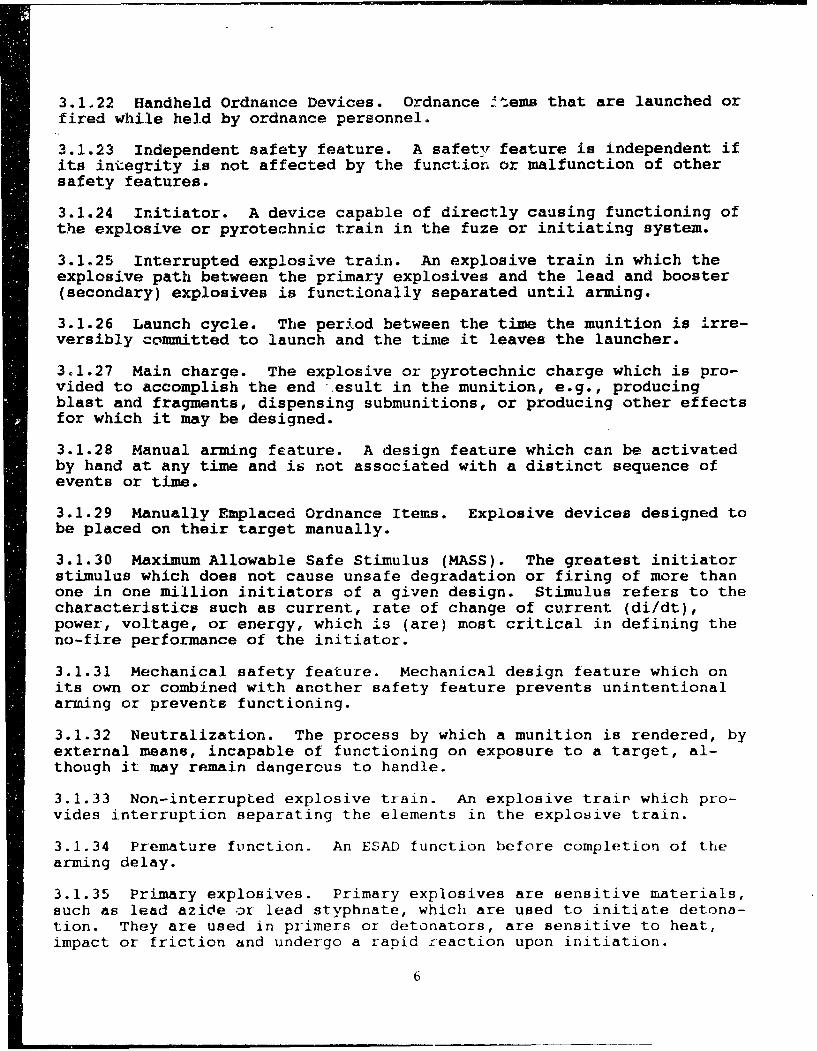
3.1.22 Handheld Ordnance Devices. Ordnance ftems that are launched orfired while held by ordnance personnel.
3.1.23 Independent safety feature. A safety feature is independent ifits integrity is not affected by the function or malfunction of othersafety features.
3.1.24 Initiator. A device capable of directly causing functioning ofthe explosive or pyrotechnic train in the fuze or initiating system.
3.1.25 Interrupted explosive train. An explosive train in which theexplosive path between the primary explosives and the lead and booster(secondary) explosives is functionally separated until arming.
3.1.26 Launch cycle. The period between the time the munition is irre-versibly committed to launch and the time it leaves the launcher.
3.1.27 Main charge. The explosive or pyrotechnic charge which is pro-vided to accomplish the end esult in the munition, e.g., producingblast and fragments, dispensing submunitions, or producing other effectsfor which it may be designed.
3.1.28 Manual arming feature. A design feature which can be activatedby hand at any time and is not associated with a distinct sequence ofevents or time.
3.1.29 Manually Emplaced Ordnance Items. Explosive devices designed tobe placed on their target manually.
3.1.30 Maximum Allowable Safe Stimulus (MASS). The greatest initiatorstimulus which does not cause unsafe degradation or firing of more thanone in one million initiators of a given design. Stimulus refers to thecharacteristics such as current, rate of change of current (di/dt),power, voltage, or energy, which is (are) most critical in defining theno-fire performance of the initiator.
3.1.31 Mechanical safety feature. Mechanical design feature which onits own or combined with another safety feature prevents unintentionalarming or prevents functioning.
3.1.32 Neutralization. The process by which a munition is rendered, byexternal means, incapable of functioning on exposure to a target, al-though it may remain dangercus to handle.
3.1.33 Non-interrupted explosive train. An explosive trair which pro-vides interruption separating the elements in the explosive train.
3.1.34 Premature function. An ESAD function before completion of thearming delay.
3.1.35 Primary explosives. Primary explosives are sensitive materials,such as lead azice or lead styphnate, which are used to initiate detona-tion. They are used in primers or detonators, are sensitive to heat,impact or friction and undergo a rapid reaction upon initiation.
6
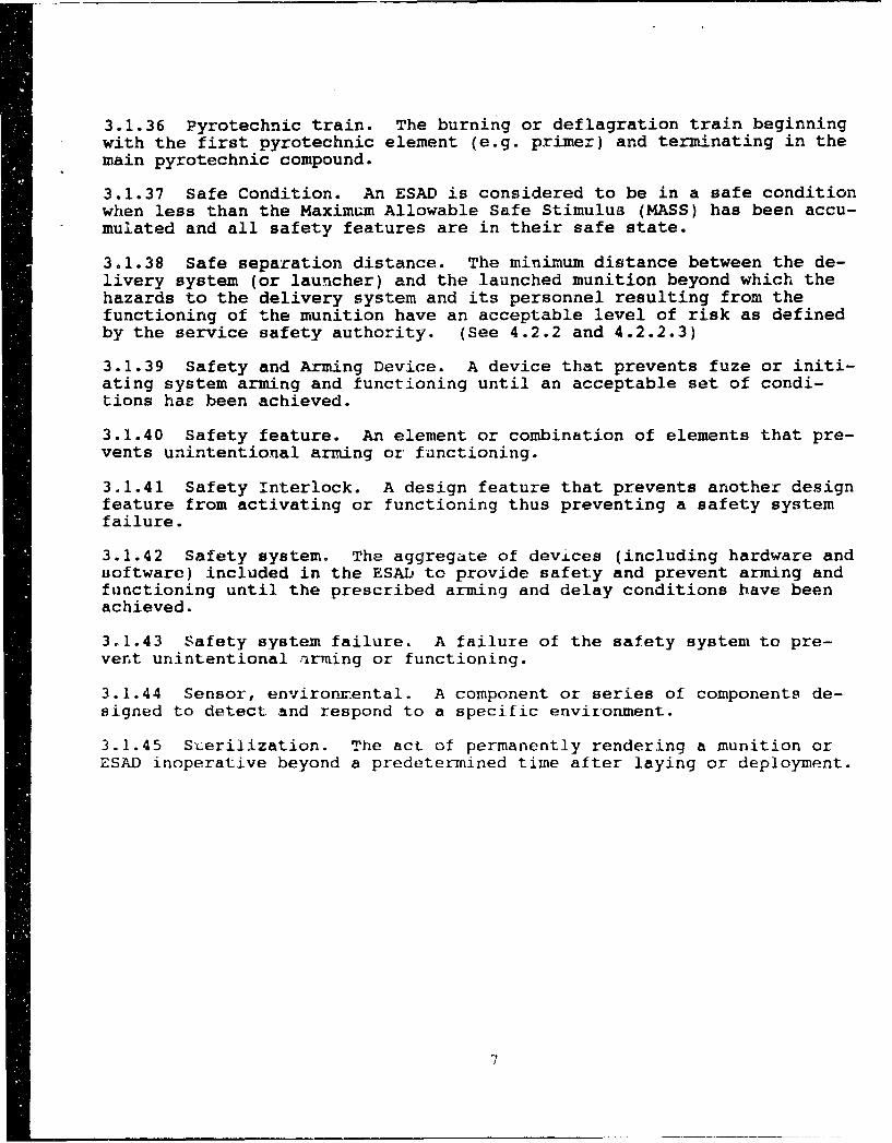
3.1.36 Pyrotechnic train. The burning or deflagration train beginningwith the first pyrotechnic element (e.g. primer) and terminating in themain pyrotechnic compound.
3.1.37 Safe Condition. An ESAD is considered to be in a safe conditionwhen less than the Maximum Allowable Safe Stimulus (MASS) has been accu-mulated and all safety features are in their safe state.
3.1.38 Safe separation distance. The minimum distance between the de-livery system (or launcher) and the launched munition beyond which thehazards to the delivery system and its personnel resulting from thefunctioning of the munition have an acceptable level of risk as definedby the service safety authority. (See 4.2.2 and 4.2.2.3)
3.1.39 Safety and Arming Device. A device that prevents fuze or initi-ating system arming and functioning until an acceptable set of condi-tions has been achieved.
3.1.40 Safety feature. An element or combination of elements that pre-vents unintentional arming or functioning.
3.1.41 Safety Interlock. A design feature that prevents another designfeature from activating or functioning thus preventing a safety systemfailure.
"3.1.42 Safety system. The aggregate of devices (including hardware andsoftware) included in the ESAD to provide safety and prevent arming andfunctioning until the prescribed arming and delay conditions have beenachieved.
3.1.43 Safety system failure. A failure of the safety system to pre-vent unintentional arming or functioning.
3.1.44 Sensor, environinental. A component or series of components de-signed to detect and respond to a specific environment.
3.1.45 Sterilization. The act of permanently rendering a munition orESAD inoperative beyond a predetermined time after laying or deployment.
7
4. GENERAL REQUIREMENTS
-4..± General
The following general requirements apply to all Electronic Safetyand Arming Devices and their components within the scope of this docu-ment.
4.1.1 Compatibility of fuze or initiating system elements
Explosive compositions in fuzes and initiating systems shall bequalified in accordance with NAVORD OD 44811 and NAVSEATNST 8020.5B intheir intended roles as explosive train cor inents. All fuze or initi-ating system materials shall be chosen to compatible and stable sothat under all credible life-cycle conditions none of the following canoccur in an unarmed fuze:
a. Premature armingb. Dangerous ejection of materialc. Burning, deflagration, explosion, or detonation of the initia-
tor, detonator, lead or boosterd. An increase in the sensitivity of explosive train components
beyond the level at which they were approved for service usee. Compromise of safety, sterilization, or explosive ordnance
disposal featuresf. Production of unacceptable levels of toxic or other hazardous
materials or by-productoThe compatibility of materials shall be verified by testing.
4.2 ESAD Safety Systems
The ESAD safety system design shall not contain any common mode orsingle point failures that could permit unintentional or early arming.The following general requirements apply to the design of safety sys-tems. The ESAD design shall prohibit premature ESAD arming or function-ing as a result of any or all of its electrical safety or energy controlfeatures failing in any given state. These failure modes include eitherrandom or induced failures which occur prior to, during, or after appli-cation of electrical power to the ESAD.
4.2.1 Safety redundancy.
ESAD safety systems shall contain at least two independent safetyfeatures, each of which shal. prevent unintentional arming of the ESAD.The stimuli enabling the safety features (see Figure 1) shall be derivedfrom different environments. Operation of at least one of these safetyfeatures shall deperd on sensing an environment after first motion inthe launch cycle or on sensing a post-launch environment. The effec-tiveness of each safety feature shall be determined by tests and anally-ses that account for all credible environments in the logistic cycle.
4.2.1.1 Enabling enviroatnments. Environments that enable safety fea-tures in ESADs shall not: be conditions that pre-exist within the muni-tion. Environments may be c.,ombined to enable electrical or inechanicaJ
8
safety features, and a single environment. may contribute to the enablingof more than one safety feature. No single environment shall be capable3f enabling more than one safety feature•, At least one sensed envi•-ronment shall be verified continuou•ly until munition safe separation isassured unless no practical enviionment is available. An action takento initiate launch may be considered an environment if: the action isintentional and occurs only when launch is intended, and; the signalgenerated by the action irreversibly conmits the munition to complete,the launch cycle.
4.2.1.2 Dynamic electrical safety feature(s). The ESAD shall incorpo-rate at least one safety feature (energy interrupter) which shall pre-vent unintentional arming when any combination of or all energy inter-rupters fail statically. This requires that at least one of the energyinterrupters be electrically dynamic in its enabling functions duringthe arming process (see definition in 3.1.10). Improper operation orfailure of the dynamic safety feature shall result in any arming energybeing dissipated and shall prevent its accumulation above the safe c-on-dition (See section 3.1.37). The dynamic electrical energy interruptershall be enabled by an environment after first motion in the launch se-quence or on sensing a post launch environment. The environment mustnot be produced within the pre-launched weapon system or by the pre-launch environment. For systems that accumulate functioning energy fromthe post launch environment, see paragraph 5.2.4.1.
4.2.1.3 Launch environments. For warhead fuzes, operation of at leastone of the independent features shall depend on sensing au environmentafter first motion in the launch cycle or on sensing Li post-launch envi-ronment.
4.2.1.4 Physical partitioning. Electronic circuits controlling inde-pendent safety features shall be physically partitioned into func-tionally dissimilar elements, neither of which can independently arm thesystem. The functional partitioning shall ensure that the circuits areimmune to common mode failures resulting from any credible environmentalhazards. System arming shall not. occur if any system electrical powersources, electrical grounds, or system frequencies are connected or dis-connected in a credible manner to any point in the circuit.
4.2.1.5 Manual Arming Features. When a manual arming feature is used(see definition 3.1.28), such as a lanyard or umbilical disconnect, thedesign of the ESAD shall meeýt the system safety failure rate after thisarming feature has been compromised (e.g., by removal of the lanyard)unless it can be shown by analysis and te3t that the feature will not becompromised by any credible life cycle environment.
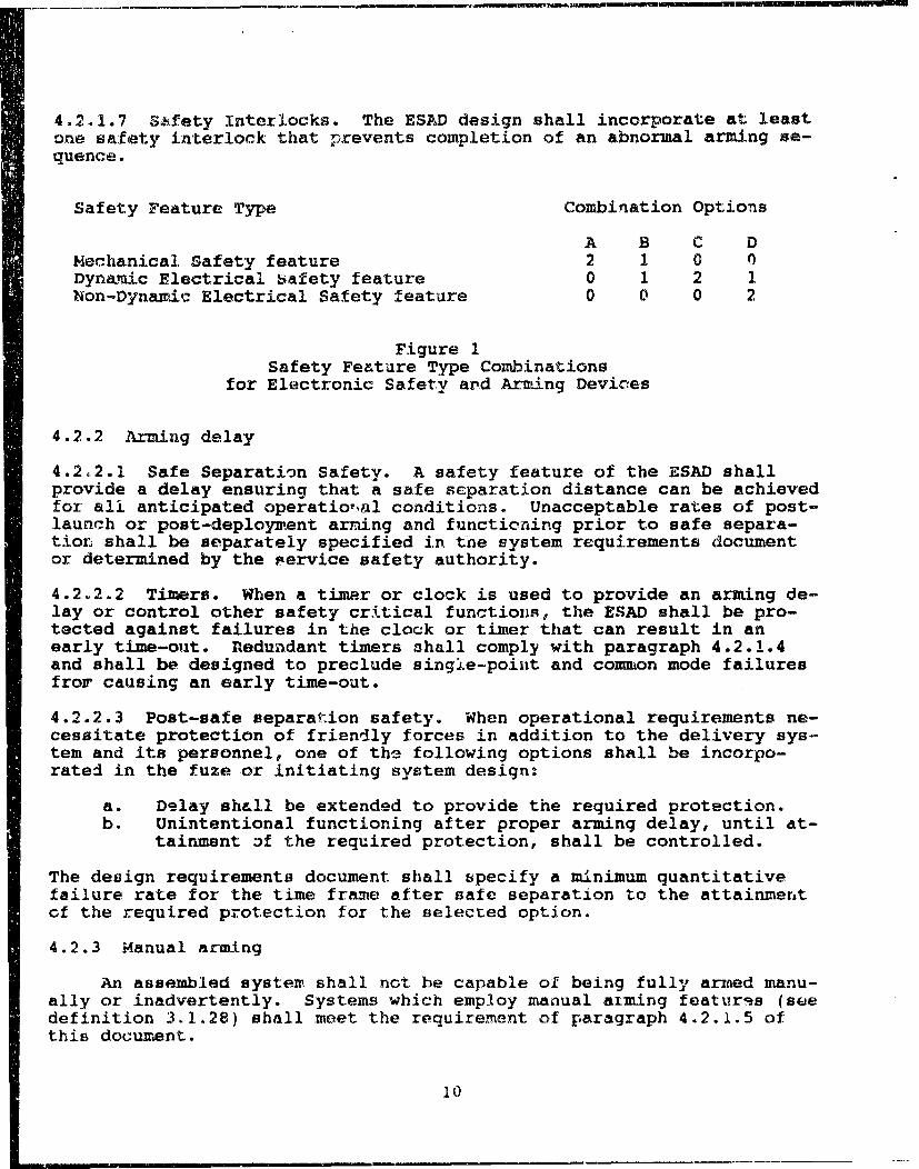
4.2.1.6 Safety feature type combinations. Dynamic safety features prc-vide greater safety than non-dynamic electrical safety features. There-fore, the number of required safety features in a system varies with thetype. Figure 1 shows combinations are acceptable when supported by theappropriate satety analyses and test data. All safet, features shall beindependent (see 3.1.23). Combination option A represents compliancewith MIL-STD-1316.
9
4.2.1.7 Safety Interlocks. The ESAD design shall incorporate at leastone safety interlock that prevents completion of an abnormal arming se-quence.
Safety Feature Type Combination Options
A B C DMechanical Safety feature 2 1 0 nDynami.c Electrical Safety feature 0 1 2 1Non-Dynamic Electrical Safety feature 0 0 0 2
Figure 1Safety Feature Type Combinations
for Electronic Safety ard Arming Devices
4.2.2 Arming delay
4.2.2.1 Safe Separation Safety. A safety feature of the ESAD shallprovide a delay ensuring that a safe separation distance can be achievedfor all anticipated operatio,•al conditions. Unacceptable rates of post-launch or post-deployment arring and functioning prior to safe separa-tior shall be separately specified in the system requirements documentor determined by the service safety authority.
4.2.2.2 Timers. When a timer or clock is used to provide an arming de-lay or control other safety critical functions, the ESAD shall be pro-tected against failures in the clock or timer that can result in anearly time-out. Redundant timers shall comply with paragraph 4.2.1.4and shall be designed to preclude single-point and common mode failuresfrom causing an early time-out.
4.2.2.3 Post-safe separation safety. When operational requirements ne-cessitate protection of friendly forces in addition to the delivery sys-tem and its personnel, one of the following options shall be incorpo-rated in the fuze or initiating system design:
a. Delay shall be extended to provide the required protection.b. Unintentional functioning after proper arming delay, until at-
tainment Df the required protection, shall be controlled.
The design requirements document shall specify a minimum quantitativefailure rate for the time frame after safe separation to the attainmentof the required protection for the selected option.
4.2.3 Manual arming
An assembled system shall not be capable of being fully armed manu-ally or inadvertently. Systems which employ manual aiming features (soedefinition 3.1.28) shall meet the requirement of paragraph 4.2.1.5 ofthis document.
10
4.2.4 Logic functions
Any logic functions related to safety elements performed by thesystem shall be implemented in hardware or embedded in firmware.
4.2.5 Firmware
Firmware shall not be erasable or alterablf, by any credible envi-ronment encountered in the logistic cycle. For systems in which a firecontrol system or other system iF required to preset data in firmrware,the munition and fuze shall be designed such that they are incapable ofaltering or erasing the firmware data after loading. The munition shallbe capable of performing reasonableness and sanity checks on the dataloaded by the fire control system or other system.
4.2.6 Application Specific Integrated Circuits
4.2.6.] ASIC Design
Application Specific Integrated Circuits (ASICs) shall comply thecircuit design requirements of this document including sections 4.2.1.4,4.2.4, 4.2.5, and other sections as applicable. ASICs shall not incor-porate unnecessary gates or functions in the design. Power circuitsshould be isolated from signal or low power logic lines to the maximumextent practical through pin selection and circuit design. Multiple pingrounds are recommended to reduce ground inductance. High current tran-sients (e.g., capacitor discharge) should not discharge through safetylogic circuits.
4.2.6.2 ASIC Testing
ASICs used fnr safety critical circuits should be subjected to dy-namic burn-in tescs rather than static burn-in tests, i.e., the circuitshould be required to operate during the burn-in test.
4.3 Safety system failure rate
The ESAD safety system failure rate shall be calculated by perform-ing safety analyses and tests and shall be verified to the maxi:mtm ex-tent practical by test and analysis during evaluation. As a minimum re-quirement, the safety system failure rate shall not exceed one failurein one million systems prior to intentional initiation of the arming se-quence. For tube launched ammunition, this requirement extends to tubeexit. Rates of post-launch arming and functioning prior to safe sepa-ration shall not exceed those specified in the system requirements docu-ment or as determined by the service safety authority.
4.3.1 Analyses
Analyses shall be performed to identify hazardous conditions forthe purpose of their elimination or control. A Preliminary Hazard Anal-ysis shall be conducted to identify the hazards of normal and abnormalenvironments, conditions and personnel actions that may occur in thephases before safe separation or disposal of the munition. This analy-
SIii
sis shall be used in the preparation of system design requirements.Hazard analyses, such as Failure Modes and Hazardoue Effects Analyses-(FMHEA), Failure Modes and Effects Criticality Analysis (FMECA), andFault Tree Analyses (FTA), shall be conducted to arrive at an estimateof the safety system failure rate and to identify dny potential singlepoint failure or common mode failures. These analyses shall be reviewedby an independent establishment approved by the cognizant reviewing au-thority. eor any systems using an embedded controller, micro-processoror other computing device, the analyses shall include a determination ofthe contribuition of the embedded computing device, including its com-puter code to the enabling of the safety features. Where the computingdevice is shown to control or directly (critically) influence the re-moval of one or more safety features, a detailed safety analysis andsafety testing of the computer code shall be performed to ensure that nodesign weaknesses, credible failure_, or credible hardware failurespropagating through the computer code, can result in compromise of thesafety features. Techniques for conducting the FMHEA, FTA and otherhazard analyses are described in NAVORD OD 44942, AFSC Design HandbookDH 1-6, NUREG-0492, and MIL-STD-882.
4.4 Design for quality control, inspection and maintenance
a. ESADs shall be designed and documented to facilitate applica-tion of effective quality control and inspection procedures.Design characteristics critical to the safety of the ESADshall be identified to assure that the designed safety iswaintained.
b. The design of the ESAD shall facilitate the use of inspectionand test equipment for visual, physical, or electronic moni-toring of all characteristics which assure the safety and in-tended functioning at all appropriate stages. The designshould facilitate the use of automatic inspection equipment.
c. Embedded computing systems and their associated software(firmware) shall be designed and documented for ease of futuremaintenance. Software development shall be done in accordancewith accepted high quality software development procedures,such as DOD-STD-2167A.
4.5 Design approval
At the inception of engineering development, the developing activ-ity should obtain interim approval from the cognizant safety authorityof both the design concept and the methodology for assuring compliancewith safety requirements. At the completion of engineering development,the developing activity shall:
a. Exercise standing procedures in preparing for system safetyreviews other than as noted in this document.
b. Prepare an ESAD System Safety Guideline Compliance Reportdocumenting the compliance of the ESAJ) with the requirementsimposed by this document. This report shall contain a de-tailed implementation description for each requirement.
c. Provide copies3 of the ESAD System Safety Guideline ComplianceReport to the appropriate Systems Comumand offices who will
12
provide concurrence, comments and coordination of the waiver
and safety approval in accordance with current directives.
4.6 Design features
4.6.1 Stored energy
The ESAD safety system shall not utilize stored energy to enablesafety features or provide arming energy unless no adequate environmen-tally derived energy source is available. If stored energy is used, itshall be demonstrated that safety is not compromised and that the designcomplies with the requirements of 4.3 and 4.3.1. Examples of stored en-ergy components are:
a. Batteriesb. Charged capacitorsc. Compressed gasd. Explosive actuators (bellows and dimple motors, etc.)e. Loaded springs
4.6.1.1 Lithium Batteries
Lithium batteries shall not be used in ESAD designs unless alterna-tive battery designs are not available or not practical. Lithium bat-teries used in ESADs shall comply with the policy and requirements ofNAVSEA Notice 9310. This requirement applies to ESADs for devices usedaboard ships as well as those carried aboard ships in stowage.
4.6.2 Explosive ordnance disposal (EOD)
ESADs shall comply with the explosive ordnance disposal design re-quirements of MIL-STD-1902 (draft).
4.6.2.1 EOD Design Features. ESADs shall incorporate features thatfacilitate the neutralization of duds by EOD tools, equipment and proce-dures, if effective sterilization or self-destruction features are notincorporated. All ESADs shall have an EOD Render Safe Procedure and anEOD Disposal Procedure developed in accordance with MIL-STD-1902 (draft)during the development program.
4.6.2.2 EOD reviewing authority. All new or altered designs, or newapplications of approved designs, shall be presented to the affectedservice's EOD Research, Development, Test and Evaluation authority fortechnical advice and assistance in determining viable design approachesor trade-offs for EOD and approval as follows:
a. For Army: CoimnanderUS Army ARDECATTN: SMCAR-FSM-EPicatinny Arsenal, NJ 07806-5000
13
b. For Navy: Commanding OfficerNaval Explosive OrdnanceDisposal Technology CenterATTN: Fleet Liaison OfficeIndian Head, MD 20640-5070
c. For Marine Corps: Commanding OfficerNaval Explosive OrdnanceDisposal Technology CenterATTN: Marine Corps DetachmentIndian Head, MD 20640-5070
d. Fcr Air Force: Commanding OfficerNaval Explosive OrdnanceDisposal Technology CenterATTN: Detachment 63 US Air ForceIndian Head, MD 20640-5070
4.6.3 Safe condition
4.6.3.1 Safe condition assurance options. In order to allow the safecondition of an ESAD to be assured, designs shall incorporate one ormore of the following features:
a. A feature(s) that prevent the assembly of the fuzing system inother than a safe condition.
b. A feature that provides a positive means of determining thesafe condition of the system during and after assembly andwhen installing the system into a munition.
c. A feature that prevents the installation of an armed fuzingsystem into a munition.
If arming and reset of the assembled ESAD in tests is a normal procedurein manufacturing, inspection, or at any time prior to its installationinto a munition, prevention of unsafe assembly (subparagraph a) is notsufficient and the provisions of either subparagraph b or c must also bemet.
4.6.3.2 Visual indication. If visual indication of the safe-armed con-dition is to be employed in the ESAD, visible indicators shall be de-signed to provide a positive, unambiguous indication of the fuze or ini-tiating system condition. The indicators shall be designed such thatcredible failures cannot result in a false 'safe' indication. If colorcoding is used to show the fuze or initiating system safe or armedcondition, the colors shall be selected as follows:
a. Safe condition. Fluorescent green background with the letterS or word SAFE supfcrimposed thereon in white. Colors shall benonspecular.
b. Armed condition. Fluorescent red background with the letter Aor the word ARMED superimposed thereon in black. Colors shallbe nonspecular.
If other indicator capabilities are provided, they shall be designed toprovide a positive indication of the safe or armed state of the ESAD andshall preclude the inadvertuint input of any stimulus to the ESAD fromthe monitoring circuits.
14

4.6.4 Firing Stimulus Dissipation
The design of the firing circuit shall incorporate circuits or de-vices cn the firing capacitor or other energy storage device to dissi-pate accumulated firing stimuli if functioning does not occur in a rea-sonable period of time. The discharge circuits or devices shall be de-signed to fail safe (i.e., to dissipate accumulated firing stimuli inthe event of a failure) and to minimize the probability of common modefailures. The circuits shall be designed to reduce the accumulated fir-ing stimuli to a level at or below the MASS within thirty (30) minutesof the time of expected function of the ESAD.
4.7 Electromagnetic and electrical hazards
The general requirements and test methods for the design and devel-opment of electro-explosive subsystems and associated items to precludehazards from unintentional initiation are provided in MIL-STD-1512. Ap-plicable portions of this standard and those specified in 4.7.1, 4.7.2,4.7.3, and 4.7.4 shall be applied during ESAD development.
4.7.1 Electromagnetic radiation (EMR)
ESADs shall not arm or function due to Electromagnetic Radiation(EMR) in any logistic and tactical configuration until launch and safeseparation have been achieved. Electromagnetic emission sensitivity,susceptibility, or vulnerability of the ESAD shall not create a poten-tial hazard. The requirements of MIL-STD-461 and DOD-STD-1463 shall ap-ply. The general requirements and test methods to preclude hazards re-sulting from ordnance having electro-explosive devices are provided inMIL-STD-1385.
4.7.2 Electrostatic Discharge (ESD)
ESADs shall not arm or function due to Electrostatic Discharge(ESD). Requirements and test methods for ESD testing are given in MIL-STD-331.
4.7.3 Electromagnetic pulse (EMP)
ESADs shall not function due to Electromagnetic Pulse (EMP). TheEMP test environment is specified in DOD-STD-2169.
4.7.4 Lightning effects
ESADs shall not arm or function due to the effects of lightning.Requirements for lighting testing and evaluation shall be in accordancewith MIL-STD-1795 and MIL-STD-1757.
4.7.5 Power Supply Transients
ESAD circuits shall be designed to withstand any credible powersupply voltage transients in either direction.
15
4.8 Reviewing authority
All new or altered designs, or new applications of approved de-signs, shall be presented for a safety evaluation and certification ofcompliance or appropriate waiver considerations to:
Chairman,Weapon System Explosives Safety Review BoardNaval Sea Systems CommandWashington, DC 20362
16
5. DETAILED REQUIREMENTS
5.1 General
The safety criteria contained herein should be selectively appliedin accordance with the needs of specific ZESAD development programs.
5.2 Explosive trains
5.2.1 Maximum acceptable safe stimulus (MXSS) determination
The Maximum Acceptable Safe Stimulus (MASS) (see definition 3.1.24)shall be determined by analysis and testing. Testing of the initiatorat the presumed MASS shall establish that the initiators shall not de-grade or initiate with a reliability of .995 with confidence of 95%.
5.2.2 Explosive sensitivity (lead and booster explosives)
Explosives listed in Table I of MIL-STD-1316 are approved by allservices for use in a position leading to the initiation of a high ex-plosive main charge without interruption. Changes to this table mayonly be made by the procedures described in MIL-STD-1316. Explosivesnot listed in Table I must be approved by the associated safety author-ity board and an appropriate test plan developed to verify theirsuitability. Additional explosives for application to Navy devices maybe appro-ed by separate correspondence. Approved explosives shall berequalified in the ESAD and certified by the associated sdfety authorityboard as acceptable for that ESAD. The explosive material used in ESADsshall not be altered by any means (grinding, precipitation, recrystal-lization, density changes, etc.) likely to increase its sensitivity be-yond that at which the material was qualified and at which it is custom-arily used.
5.2.3 Explosive train interruption
When an element of the explosive train contains primary explosives,at least one interrupter (shutter, slider, rotor) shall separate themfrom the lead and booster explosives until the arming sequence is com-pleted. The interrupter(s) shall be directly locked mechanically in thesafe position by at least two independent safety features. The safetyfeatures shall not be removed until the arming sequence begins. If theprimary explosive material is housed in the interrupter, a single inter-rupter locked by the two independent safety features is acceptahle. Ifthe primary explosive is positioned such that safety is completely de--pendent upon the presence of an interrupter, the design shall includepositive means to prevent the fuze or initiating system from being as-sembled without the proper~y positioned interrupter. The effectivenessof the interruption shall be determined by techniques described in MIL-STD-331 during design evaluation.
17
5.2.4 Non-interrupted explosive train control
5.2.4.1 Function energy control. Explosive train interruption is notrequired when the explosive train contains only booster and lead explo-sive materials allowed by 5.2.2. One of the following methods of con-trolling function energy shall be employed to preclude arming beforeac:hieving the required arming delay:
a. For ESADs containing energy greater than the MASS prior to ex-piration of the arming delay, at least two independent energyinterrupters, each controlled by an independent safety fea-ture, shall prevent the flow of energy to the initiator untilcompletion of the safe ceparation delay. Additionally, thefuze or initiating system shall not be capable of functioningin the absence of the energy interrupter(s•. This requirementapplies to all ESAD designs that contain energy sources capa-ble of producing the MASS.
b. For systems using techniques for accumulating functioning en-ergy from the post-launch environment, the ESAD shall not per-mit any energy to reach the initiator until verification, bythe ESAD, of a proper launch and attainment of the requiredsafe separation. Additionally, any energy of the type re-quired to function the initiator which exists in the ESAD oris available from the weapon system prior to attainment of therequired arming delay shall be less than the MASS. The com-bined probability of having the MASS in the ESAD, having afailure of the energy control feature(s) and firing the ini-tiator with the MASS energy shall be compatible with the spec-ified ESAD safety system failure rate (see 4.3).
5.2.4.2 Electrical Initiator Sensitivity. The initiator for anelectrically fired non-interrupted explosive train:
a. Shall meet the characteristics listed for 1-watt/i-amp initia-tors of MIL-STD-1512
b. Shall not be capable of being initiated or degraded in an un-safe manner by any electrical potential of less than 500 volts
c. Shall not be initiated as a result of exposure of the ESAD tothe effects of lightning and specified electromagnetic radia-'ion (EMR), electrostatic discharge (ESD), electromagneticpulse (EMP) and nuclear radiation environments. Lightningtest and evaluation shall be according to DOD-STD-1795 andMIL-STD-1757. EMR requirements and evaluation shall be ac-cording to MIL-STD-461 and DOD-STD-1463. ESD tests and evalu-ations shall be in accordance with MIL-STD-331. EMP tests andevaluations shall be in accordance with DOD-STD-2163.
18
5.3 Design features
5.3.1 Sterilization/Disable/Self-destruct features
The design of the ESAD shall incorporate a planned, programmed pro-cess consistent with the particular weapon and its use that:
a. Renders the weapon permanently incapable of functioning afterspecified events and time when the weapon has served its use-ful purpose, and/or
b. Renders the weapon temporarily incapable of functioning (e.g.,by command enable/disable during launch cycle and flight) be-fore or after specified events that could endanger the launchplatform or friendly forces, and/or
c. Destroys the weapon after specified events and time when theweapon has served its useful purpose.
Designs not incorporating sterilization features shall provide justifi-cation and receive concurrence from the service safety review authority.
5.3.1.1 Sterilizacion of torpedoes and sea mines. ESADs for torpedoesand sea mines shall provide for sterilization after safe jettison, afterspecified events and time when the munition has served its useful pur-pose or when the munition is no longer capable of functioning reliably.
5.3.2 Fail-safe design
ESADs shall incorporate fail-safe design features based on theirapplicability to system requirements.
19
6. NOTES
This section contains information of a general or explanatory na-ture that may be helpful, but is not mandatory.
6.1 Intended use
This document establishes specific design safety criteria forESADs. The criterion herein must be tailored to the specific ESAD de-velopment.
6.2 Safety Review
All new or altered designs, or new applications of approved designsshall be presented to the review authority of 6.3 for a safety evalua-tion of comj iance with MIL-STD-1316 and this document. Included forpresentation shall be documentation that details the design's safety at-tributes.
6.3 Custodian of Navy approvals for in-line lead and booster explosivesand fuze and S&A designs.
ChairmanWeapon System Explosives Safety Review BoardNaval Sea Systehns CommandWashington, DC 20362
6.4 Subject term (key word) listing
Delay, armingExplosive ordnance disposalExplosive trainExplosive train interruptionFail-safeFunction, earlyFunction, prematureFuzeFuze design, eafety criteria forSafe and Axm DeviceElectronic Safe and Arm Devices
20
Appendix A
Guidelines for the Application of theESAD Technical Manual
A.1 Guidelines
The following guidelines are offered to assist the user in the in-terpretation of the requirements of the WSESRB Technical Manual. Theseguidelines attempt to describe the intent behind specific requirementswhere they are subject to interpretation. Guidelines are referenced byapplicable paragraph numbers.
A.1.1 Purpose
A.1.2 Scope of Applicability
The application of this technical manual to ESADs transported bythe Navy for other services, etc. extends only to those requirements ap-plicable to the storage and transportation of the items. Therefore,specific criteria that apply to the safety of the item during opera-tional use may not be applicable for non-Navy munitions. The applica-tion of this manual to U.S. Marine Corps developed or deployed itemsshall be to the extent specified by the Commandant, Marine Corps.
A.1.3 Excluded Munitions
This document applies to all munitions using electronic safety andarming devices except those used to initiate Nuclear warheads. It does,however, apply to ESADs used to enable other functions (e.g., rocket mo-tors) for nuclear weapons.
A.3. DEFINITIONS
A.3.1 General
A.3.1.1 Arm
The arm definition is intended to proide a distinction betweensafe to handle state and an unsafe to handle state. This definitiondoes not consider a reliable armed condition.
A.-3.1.2 Arm-Fire DevicesA.3.1.3 Arxffng delay-A.3.1.4 Ass mbled fuze or initiating systemA.3.1.5 Booster and lead explosivesA.3.1.6 Credible environmentsA.3.1.7 DudA.3.1.8 Dynamic electrical safety featureA.3.1.9 Early-functionA.3.1.10 Electronic Safety and Arnin9 DevicesA.3.1.11 Enabling
Appendix A
A.3.1.12 EnvironmentA.3.1.13 Environmental stimulusA.3.1.14 Explosive Ordnance DisposalA.3.1.15 Explosive trainA.1.1.16 Fail-safe designA.3.1.17 Firmware
Firmware is software and must be developed, analyzed and tested inaccordance with accepted software engineering methodologies and prac-tices such as those defined in DOD.-STD-2167A. Firmware shall be sub-jected to quality assurance provisiuns in the same manner as software.
A.3.1.18 Functi(onA.3.1.19 Fuze or Initiating SystemA-3.1.20 Fuze or initiating system installationA.3.1.21 Hand GrenadesA.3.1.22 Handheld Ordnance DevicesA.3.1.23 Independent safety featureA.3.1.24 InitiatorA.3.1.25 Interrupted explosive trainA.3.1.26 Launch cycleA.3.1.27 Main chargeA.3.1.28 Manual arming featureA.3.1.29 Manually Emplaced Ordnance ItemsA.3-1.30 Maximum Allowable Safe StimulusA.3.1.32 Mechanical safety featureA.3.1.32 NeutralizationA.3.1.33 Non-interrupted explosive trainA.3.1.34 Premature functionA.3-1.35 Primary explosivesA.3.1.36 Pyrotechnic trainA.3.1.37 Safe ConditionA.3.1.38 Safe separation distanceA.3.1.39 Safety and Arming DeviceA.3.1.40 Safety featureA.3.1.41 Safety InterlockA.3.1.42 Safety systemA.3.1.43 Safety system failureA.3.1.44 Sensor, enviro:nmentalA.3.1.45 Sterilization
A.4. GEVERAL REQUIREMENTS
AA4.1 General
A.4.1.1 Compatibility
A.4.2 ESAD Safety Systems
A-2

A.4.2.1 Safety redundancy
A.-4.2.1.1 Enabling environments
"At least one sensed environment shall be verified continuously un-til munition safe separation is assured unless no practical enviroranentis available." The intent of this requirement is to provide po3itiveassurance that safe separation is achieved before full arming occurs.This specific requirement aay not be possible in every situation (seetailoring guidelines in appendicies B through E). This requirement doesnot necessarily apply to ordnance not intended for use by the Navy orUSMC.
A.4.2.1.2 Dynamic electrical safety feature(s)
The dynamic safety feature is intended to provide a fail safe de-sign for at least one of the safety features. The requirement that theenabling environment be sensed continuously until safe separation isachieved will ensure that this safety feature, by itself, can provide anacceptable level of risk even in the presence of other failures.
A.4.2.1.3 Launch environments
A.4.2.1.4 Physical partitioning
"Functionally dissimilar elements" is intended to mean that the de-signs of the circuits should be substantially different in the way inwhich they function to reduce the probability of common mode failures.Examples include analog vs. digital design (e.g. timers) or microproces-sor vs. discrete component designs. Digital circuits and microproceJ-sors are somewhat more susceptable to EMI and ESD which could inducecommon mode failures. Another intent is to preclude having tha elementsof the same circuit controlling two safety features. This increases therisk of a single point failure affecting both fcatures. Each circuitshould control a safety feature (or outputs from both may control bothfeatures). Acceptable designs would include those that partition thecircuits controlling the arming interruption into two physically dissim-ilar elements, provided that physically dissimilar is not interpreted asbeing minor design or fabrication differences.
"System arming sbali not occur if any system electrical powersources, electrical grounds, or system frequencies are connected or dis-connected in a credible manner to any point in the circuit." This re-quirement is intLnded to require the designer to demonstrate that theESAD safety system cannot be compromised by a simple short of a ground,power, or normally occurring frequency source to any point in the cir-cuit. Therefore, if a dynamic safety feature is driven at a certainfrequency, the designer must ensu:re that the specific frequency is notpresent anywhere in the system (whether part of the ESAO or any closelyrelated component) or thet it is ;Lmpossible fcr that frequency to com-promise the ESAD armir l system. Note that frequency harmonics must beaddressed (e.g., a 12kHz oscillator in tie circuit may provide a 36kHzsignal possibly causing comprom.se of a dyna.mic safety feature intended
A-3
to opezate at 3CkHz) and frequencies derived from the environment (e.g.,
munition spin rate).
A.4.2.1.5 Manual Arming Features
"The design of the ESAD shall meet the system safety failure rateafter [the manual] arming feature has been compromised...unless it canbe shown by analysis and test that the feature will not be compromisedby any credible life cycle environment." The probability of occurrenceof compromise of the manual arming feature should be shown to be accept-able to the cognizant reviewing authority. For munitions transported bythe Navy, the credible life cycle environment shall address those evolu-tions of transportation, handling and stowage by the Navy. Intentionalor deliberate compromise of the feature by personnel is not consideredto be within the scope of this requirement.
A.4.2.l.6 Safety feature type combinations
Item A in table 1 can represent either an interrupted explosivetrain design that complies with MIL-STD-1316 or a design that providesmechanical safety features on an electrical circuit that complies withthe intent of MIL-STD-1316. Note that switches, relays, and simtila" de-vices that can interrupt the flow of electrical energy are consideredstatic (generally) electrical features, not mechanical safety features.
A.4.2.1.7 Safety Interlocks
The safety interlock may be as simple as a monitor that p.aUi,,ventscompletion of the arming sequence in the evert of an inccerruct'. sequenceof environments or timing problem, or a design that requires the envi-ronments to occur sequentially. Designs will be evlIuated on An indi-vidual basis.
A.4.2.2 Arming delay
A.4.2.2.1 Safe Separation Safety
Safe separation requirem-nts should be specifiLd in, the myrte: de-•sign documents. Acceptable levels of risk to the launching pjlaC±rai andpersonnel must also be documented in the system design requirements.The design of the ESAD shall provide for a safe separation that me-etthe requirements and intent of the system design Bspocitication. Systemsfor which an acceptable level of risk has not been iderntified are sub-ject to having a determination atade by the service safety autiho city.
A.4.,2.2.2 Timers
Early time out of a timer can be prevented in several ways. Redun-dant timers is one method that can be applied, however, 1,he timers shallbe designel to preclude commion mode or single point failures. Alternatemethods include using analog bandpass filters or tuned .ircuitL on atimer output that will permit only frequencies within a specified rangeto pass. Tuning voltage conversion circuits in anothei method that may
A-4
be employed. Note that the requirement for physical partitioning would
apply to any design involving redundant timers.
A.4.2.2.3 Post-safe separation safety
The requirements for and acceptable risk fo:ý post safe separationsafety should be clearly specified in the system design documents. Sys-tems will be evaluated on an individual basis.
A.4.2.3 Manual arming
A.4.2.4 Logic functions
i.4.2.5 Firmware
A.4.2.6 Application Specific Integrated Circuits
A.4.2.6.1 ASIC Design
"ASICs shall not incorporate unnecessary gates or functions in thedesign." This requirement is intended to apply to circuit functionsthat are not necessary to the operation of the ASIC in the application,or the testing and verification of ASIC operation during final accep-tance, burn-in, or after installation. Note that programmable logic ar-rays are not automatically excluded from use by this requirement. Ex-cess transistors not utilized by the ASIC design are not considered un--necessary gates or functions unless they have been inter-connected intoa functional circuit.
A.4.2.6.2 ASIC Testing
A.4.3 Safety system failure rate
A.4.3.1 Analyses
Software Safety: Software that directly influences the enabling ofan energy interruptor includeo any signal generated by a microprocessoror other controller that can cause or allow the early or premature en-abling of that energy interruptor. In other words, if a safety inter-lock is included in the software that monitors the arming sequence andcauses an interruption in the event of an out-of sequence event, thatsoftware must be considered safety critical and subject to the appropri-ate analysis and testing. It the software is an additional control oithe energy interruptor and cannot cause or allow a early or prematurearming or enabling of the interlock, it is not safety critical and doesnot require the same degree of analysis and test. If software is usedto provide for post-safe separation safety, the software must be fac-tored into the overall risk assessment for this operational mode.
A•.4.4 Design for quality control
Subparagraph c:E"Software development shall be done in accordance with accepted
high quality software development procedures, such as DOD-STD-2167A."
A-5
Specific interpretation of what constitutos high quality software devel-opment procedures should be open to interpretation by the service safetyreviewing authority.
N.4.5 Design approval
The cognizant safety authority has responsibility for the reviewand approval of ESAD designs during various stages of development.Their interpretation of the design criteria shall establish the prece-dent.
A.4.6 Design features
A.4.6.1 Stored energy
Stored energy sources shall not be used in ESADs unless there areno practical environmentally derived energy sources. An ESAD is consid-ered to haie atored energy if it is capable of accumulating a firingstimulus equ&l to or greater than the MASS. Capacitors that are chargedimmediately prior to launch are considered stored energy. Batteries inany form are considered stored energy even if they are normally initi-ated after launch. ESADs that do not contain sufficient energy to gen-erate the MASS or are designed such that a firing stimulus cannot be ac-cumulated even in the presence of credible failures, and rely on envi-ronmentally derived energy sources to acuumulate the firing stimulus arenot considered to have stored energy.
A.4.6.1.I Lithium Batteries
Certain lithium battery designs have been shown to pose potentialhazards to personnel and equipnent. Due to the nature of some of thesehazards, the Navy has issued policies regarding tha use of lithium bat-teries in NAVOEA Notice 9310. This Notice also establishes guidelinesand requirements for the design and testing of lithium batteries. Alldevices containing lithium batteries, whether used aboard ship or car-ried aboard ship, must comply with NAVSEA Notice 9310.
A.4.6.2 Explosive ordnance disposal (EOD)
It is the intent of the WSESRB to have full involvement of the Ex-plosive Ordnance Disposal community in the design and development of mu-nitionsi, including their fuzing systems. Designs deemed unacceptable orhigh-risk by EOD shall be considered unacceptable by the WSESRB.
A.4.6.2.1 EOD Design Features
A.4.6.2.2 EOD reviewing authority
A.4.6.3 Safe condition
A.4.6.3.1 Safe condition assurance options
A-6
A.4.6.3.2 Visual indication
This paragraph is intended to allow the option of incorporating avisual indication of the safe-arm status of the ESAD.
A.4.6.4 Firing Stimulus Dissipation
The firing stimulus dissipation mechanism should not be subject tosingle point or ccmmon mode failures. In addition, the mechanism shallbe implemented such that failure of the dynamic safety feature will al-low the firing stimulus to dissipate within the specified time.
A.4.7 Electromagnetic and electrical hazards
A.4.7.1 Electromagnetic radiaticn (EMR)
The ESAD shall remain operable after exposure to the EMR(susceptability and vulnerability) test environments.
A.4.7.2 Electrostatic Discharge (ESD)
The intent of this requirement is to ensure that electrostatic dis-charge, whether Lluring manufacture, assembly, testing, or handling doescompromise the safety of the ESAD.
A.4.7.3 Electromagnetic pulse (EMP)
The intent of this requirement is to ensure that EMP effects cannotcompromise the safety of the ESAD. The ESAD should also remain operableafter exposure to this environment.
A.4.7.4 Lightning effects
The intent of this requirement is to ensure that lightning effectscannot compromise the safety of the ESAD.
A.4.7.5 Power Supply Transients
The intent of this requirement is to ensure that power supply tran-sients, whether as a result of normal or abnormal operation, cannot com-promise the safety of the ESAD. The ESAD should also remain operableeven in the presence of normal transients.
A.4.8 Reviewing authority
A. i. DETAILED REQUIREMENTS
A.5.1 General
A.5.2 Explosive trains
A.5.2.1 Maximum acceptable safe stimulus (MASS)
A.5.2.2 Explosive sensitivity
A-7
A.5.2.3 Explosive train interruption
This paragraph is included in the document for completeness. Ifprimary explosives are used, the explosive train must be physically in-terrupted.
A.5.2.4 Non-interrupted explosive train control
A.5.2.4.1 Function energy control
A.5.2.4.2 Electrical Initiator Sensitivity
A.5.3 Design features
A.5.3.1 Sterilization/Disable/Self-destruct
A.5.3.1.1 Sterilization of torpedoes
A.5.3.2 Fail-safe design
The dynamic safety feature should normally provide a fail-safe de-sign for one safety feature. The safety interlock monitoring the armingsequence may provide for a fail-safe design in the event the othersafety feature(s) fail statically.
A.6. NOTES
A.6.1 Intended use
Although this document is being developed for application to Navyemployed systems, it will be used to evaluate multiple service weaponsystems.
A.6.2 Safety Review
A.6.3 Custodian of Navy approvals
A.6.4 Subject term (key word) listing
Appendix B
Application of the Design Criteriato Arm-Fire Devices
B.1.0 To Be Determined
Appendix B

* Appendix C
Application of the Design Criteriato Hand Emplaced Ordnance
C.1.0 To Be Determined
Appendix C
Appendix D
Application of the Design Criteriato Hand-Held Ordnance
D.1.0 To Be Determined
Appendix V

Appendix E
Application of the Design Criteriato Hand Grenades
E.o.0 To Be Determined
Appendix E