Embed Size (px)
Citation preview

Surelock McGill Ltd, 26 The Business Centre, Molly Millars Lane, Wokingham, Berkshire RG41 2QY Tel +44 (0) 118 977 2525 Facsimile +44 (0) 118 977 1913 Email [email protected] Web www.surelockmcgill.com
In accordance with our policy of continued development and improvement we reserve the right to make changes in design and specifications without notice.
Technical InformationThis section of the catalogue provides technical information that will help specify, install and maintain Surelock McGill devices and components. The topics are listed below:
Blast Protection Blast protection levels, bolt sizes and their material, bolt & Containment supports, keeps and other components to meet your requirement.
Wiring Electrical wiring information required to connect the built-in circuits that are used to provide monitoring and actuation facilities on a Surelock McGill system.
Electrical Ratings Voltages and current ratings to provide monitoring and actuation facilities.
Installation A generic guide to the installation of Surelock McGill systems.
Maintenance General guidance on the maintenance of Surelock McGill systems to ensure continued good performance.
Hinge Calculations Hinge loading and the size of Surelock McGill hinges required for a particular door.
Surelock McGill LTD26 The Business Centre,Molly Millars Lane, WokinghamBerkshire, RG41 2QY
EN179:2008
SL315/325 ABB005 37601351AA
Year of manufacture: 2008 Certifi cation body reference 1121
Projection category - grade 1 Field of door operation - category A
Fixing instructions Emergency exit device - Slimline
SL315/SL325
For single leaf outward opening doors
SF-8910-0003
Technical Information P2 05.10
Surelock McGill Ltd, 26 The Business Centre, Molly Millars Lane, Wokingham, Berkshire RG41 2QYTel +44 (0) 118 977 2525 Facsimile +44 (0) 118 977 1913 Email [email protected] Web www.surelock.co.uk
Technical Inform
ationTechnical Information 03.16 page 221

03.16 page 222
Surelock McGill Ltd, 26 The Business Centre, Molly Millars Lane, Wokingham, Berkshire RG41 2QY Tel +44 (0) 118 977 2525 Facsimile +44 (0) 118 977 1913 Email [email protected] Web www.surelockmcgill.com
Technical index
Slimline fixing instruction example 223
Slimline restraint setting and adjustment 229
Stirling fixing instruction example 231
LEO fixing instruction example 234
1. Fixing instructions
Wiring example - status monitoring & solenoid lock release 236
Solenoid power consumptions 236
Cable loop capacities 236
2. Wiring and electrical information
Maintenance instructions and general guidelines 237
3. Maintenance instructions
Peak Permissible Loads table 238
4. Blast information
Surelock Hinge loading Chart 239
5. Hinge calculations
Technical Information

03.16 page 223
Surelock McGill Ltd, 26 The Business Centre, Molly Millars Lane, Wokingham, Berkshire RG41 2QY Tel +44 (0) 118 977 2525 Facsimile +44 (0) 118 977 1913 Email [email protected] Web www.surelockmcgill.com
Surelock McGill LTD26 The Business Centre,Molly Millars Lane, WokinghamBerkshire, RG41 2QY
EN179:2008
SL315/325 ABB005 37601351AA
Year of manufacture: 2008 Certification body reference 1121
Projection category - grade 1 Field of door operation - category A
Fixing instructions Emergency exit device - Slimline
SL315/SL325
For single leaf outward opening doors
SF-8910-0003
Technical Information
03.16 page 224
Surelock McGill Ltd, 26 The Business Centre, Molly Millars Lane, Wokingham, Berkshire RG41 2QY Tel +44 (0) 118 977 2525 Facsimile +44 (0) 118 977 1913 Email [email protected] Web www.surelockmcgill.com
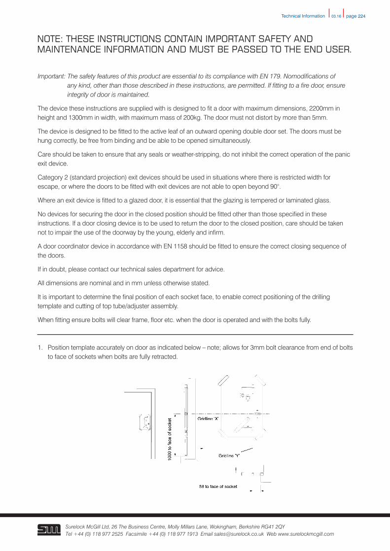
NOTE: THESE INSTRUCTIONS CONTAIN IMPORTANT SAFETY AND MAINTENANCE INFORMATION AND MUST BE PASSED TO THE END USER.
Important: The safety features of this product are essential to its compliance with EN 179. Nomodifications of any kind, other than those described in these instructions, are permitted. If fitting to a fire door, ensure integrity of door is maintained.
The device these instructions are supplied with is designed to fit a door with maximum dimensions, 2200mm in height and 1300mm in width, with maximum mass of 200kg. The door must not distort by more than 5mm.
The device is designed to be fitted to the active leaf of an outward opening double door set. The doors must be hung correctly, be free from binding and be able to be opened simultaneously.
Care should be taken to ensure that any seals or weather-stripping, do not inhibit the correct operation of the panic exit device.
Category 2 (standard projection) exit devices should be used in situations where there is restricted width for escape, or where the doors to be fitted with exit devices are not able to open beyond 90°.
Where an exit device is fitted to a glazed door, it is essential that the glazing is tempered or laminated glass.
No devices for securing the door in the closed position should be fitted other than those specified in these instructions. If a door closing device is to be used to return the door to the closed position, care should be taken not to impair the use of the doorway by the young, elderly and infirm.
A door coordinator device in accordance with EN 1158 should be fitted to ensure the correct closing sequence of the doors.
If in doubt, please contact our technical sales department for advice.
All dimensions are nominal and in mm unless otherwise stated.
It is important to determine the final position of each socket face, to enable correct positioning of the drilling template and cutting of top tube/adjuster assembly.
When fitting ensure bolts will clear frame, floor etc. when the door is operated and with the bolts fully.
1. Position template accurately on door as indicated below – note; allows for 3mm bolt clearance from end of bolts to face of sockets when bolts are fully retracted.
Technical Information
03.16 page 225
Surelock McGill Ltd, 26 The Business Centre, Molly Millars Lane, Wokingham, Berkshire RG41 2QY Tel +44 (0) 118 977 2525 Facsimile +44 (0) 118 977 1913 Email [email protected] Web www.surelockmcgill.com
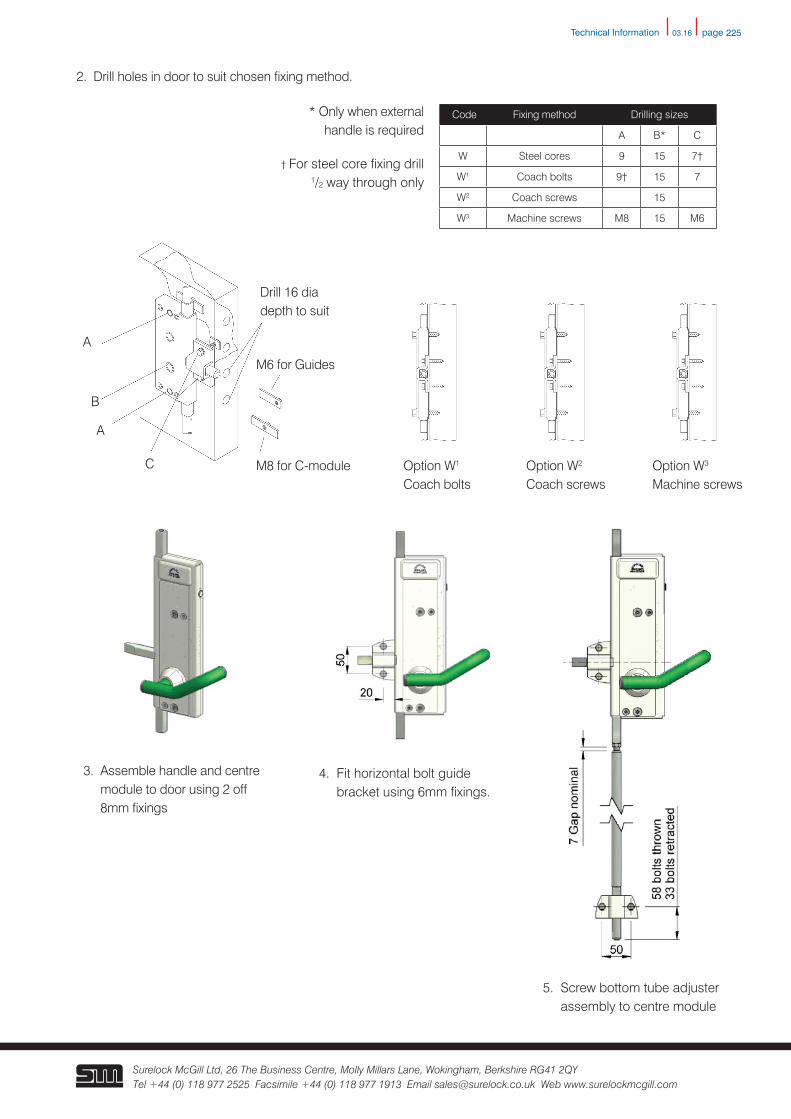
5. Screw bottom tube adjuster assembly to centre module
2. Drill holes in door to suit chosen fixing method.
3. Assemble handle and centre module to door using 2 off 8mm fixings
4. Fit horizontal bolt guide bracket using 6mm fixings.
A
A
B
C
Drill 16 dia depth to suit
M6 for Guides
M8 for C-module Option W1 Coach bolts
Option W2 Coach screws
Option W3 Machine screws
Code Fixing method Drilling sizes
A B* C
W Steel cores 9 15 7†
W1 Coach bolts 9† 15 7
W2 Coach screws 15
W3 Machine screws M8 15 M6
* Only when external handle is required
† For steel core fixing drill 1/2 way through only
Technical Information
03.16 page 226
Surelock McGill Ltd, 26 The Business Centre, Molly Millars Lane, Wokingham, Berkshire RG41 2QY Tel +44 (0) 118 977 2525 Facsimile +44 (0) 118 977 1913 Email [email protected] Web www.surelockmcgill.com
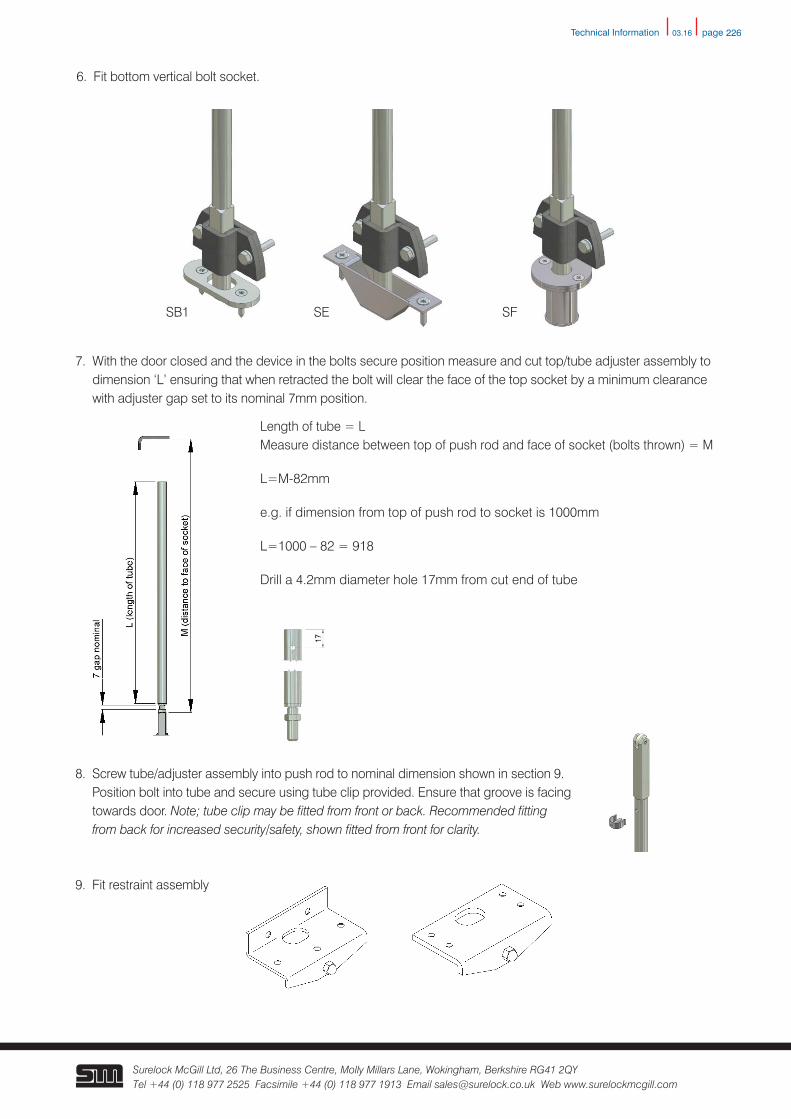
6. Fit bottom vertical bolt socket.
7. With the door closed and the device in the bolts secure position measure and cut top/tube adjuster assembly to dimension ‘L’ ensuring that when retracted the bolt will clear the face of the top socket by a minimum clearance with adjuster gap set to its nominal 7mm position.
Length of tube = L Measure distance between top of push rod and face of socket (bolts thrown) = M
L=M-82mm
e.g. if dimension from top of push rod to socket is 1000mm
L=1000 – 82 = 918
Drill a 4.2mm diameter hole 17mm from cut end of tube
8. Screw tube/adjuster assembly into push rod to nominal dimension shown in section 9. Position bolt into tube and secure using tube clip provided. Ensure that groove is facing towards door. Note; tube clip may be fitted from front or back. Recommended fitting from back for increased security/safety, shown fitted from front for clarity.
9. Fit restraint assembly
SB1 SE SF
Technical Information
03.16 page 227
Surelock McGill Ltd, 26 The Business Centre, Molly Millars Lane, Wokingham, Berkshire RG41 2QY Tel +44 (0) 118 977 2525 Facsimile +44 (0) 118 977 1913 Email [email protected] Web www.surelockmcgill.com
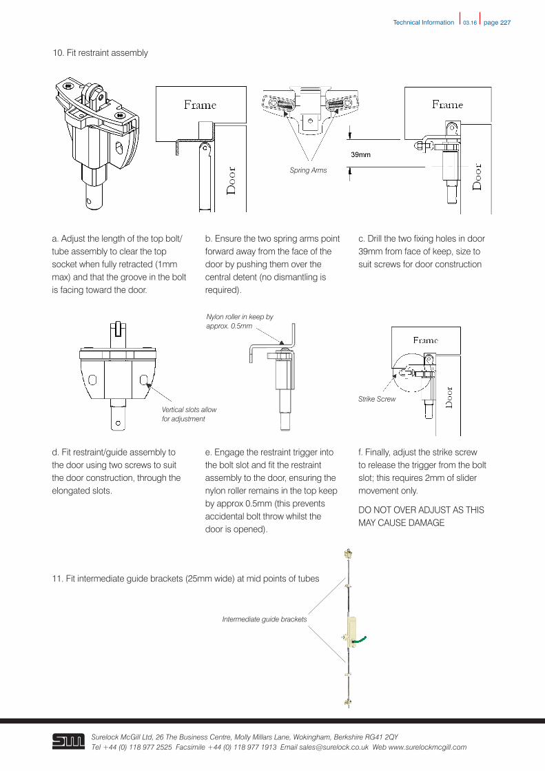
10. Fit restraint assembly
a. Adjust the length of the top bolt/tube assembly to clear the top socket when fully retracted (1mm max) and that the groove in the bolt is facing toward the door.
b. Ensure the two spring arms point forward away from the face of the door by pushing them over the central detent (no dismantling is required).
c. Drill the two fixing holes in door 39mm from face of keep, size to suit screws for door construction
11. Fit intermediate guide brackets (25mm wide) at mid points of tubes
Spring Arms
d. Fit restraint/guide assembly to the door using two screws to suit the door construction, through the elongated slots.
e. Engage the restraint trigger into the bolt slot and fit the restraint assembly to the door, ensuring the nylon roller remains in the top keep by approx 0.5mm (this prevents accidental bolt throw whilst the door is opened).
f. Finally, adjust the strike screw to release the trigger from the bolt slot; this requires 2mm of slider movement only.
DO NOT OVER ADJUST AS THIS MAY CAUSE DAMAGE
Vertical slots allow for adjustment
Nylon roller in keep by approx. 0.5mm
Strike Screw
Intermediate guide brackets
Technical Information
03.16 page 228
Surelock McGill Ltd, 26 The Business Centre, Molly Millars Lane, Wokingham, Berkshire RG41 2QY Tel +44 (0) 118 977 2525 Facsimile +44 (0) 118 977 1913 Email [email protected] Web www.surelockmcgill.com
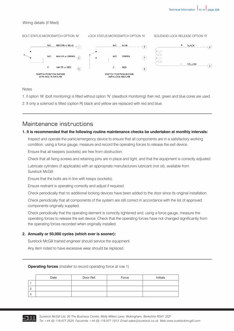
Wiring details (if fitted)
Notes
1. if option ‘M’ (bolt monitoring) is fitted without option ‘N’ (deadlock monitoring) then red, green and blue cores are used.
2. If only a solenoid is fitted (option R) black and yellow are replaced with red and blue.
Maintenance instructions1. It is recommended that the following routine maintenance checks be undertaken at monthly intervals:
Inspect and operate the panic/emergency device to ensure that all components are in a satisfactory working condition; using a force gauge, measure and record the operating forces to release the exit device.
Ensure that all keepers (sockets) are free from obstruction.
Check that all fixing screws and retaining pins are in place and tight, and that the equipment is correctly adjusted.
Lubricate cylinders (if applicable) with an appropriate manufacturers lubricant (not oil), available from Surelock McGill.
Ensure that the bolts are in line with keeps (sockets).
Ensure restraint is operating correctly and adjust if required.
Check periodically that no additional locking devices have been added to the door since its original installation.
Check periodically that all components of the system are still correct in accordance with the list of approved components originally supplied.
Check periodically that the operating element is correctly tightened and, using a force gauge, measure the operating forces to release the exit device. Check that the operating forces have not changed significantly from the operating forces recorded when originally installed.
2. Annually or 50,000 cycles (which ever is sooner):
Surelock McGill trained engineer should service the equipment.
Any item noted to have excessive wear should be replaced.
Operating forces (installer to record operating force at row 1)
BOLT STATUS MICROSWITCH OPTION ‘M’ LOCK STATUS MICROSWITCH OPTION ‘N’ SOLENOID LOCK RELEASE OPTION ‘R’
Date Door Ref. Force Initials
1
2
3
Technical Information
03.16 page 229
Surelock McGill Ltd, 26 The Business Centre, Molly Millars Lane, Wokingham, Berkshire RG41 2QY Tel +44 (0) 118 977 2525 Facsimile +44 (0) 118 977 1913 Email [email protected] Web www.surelockmcgill.com
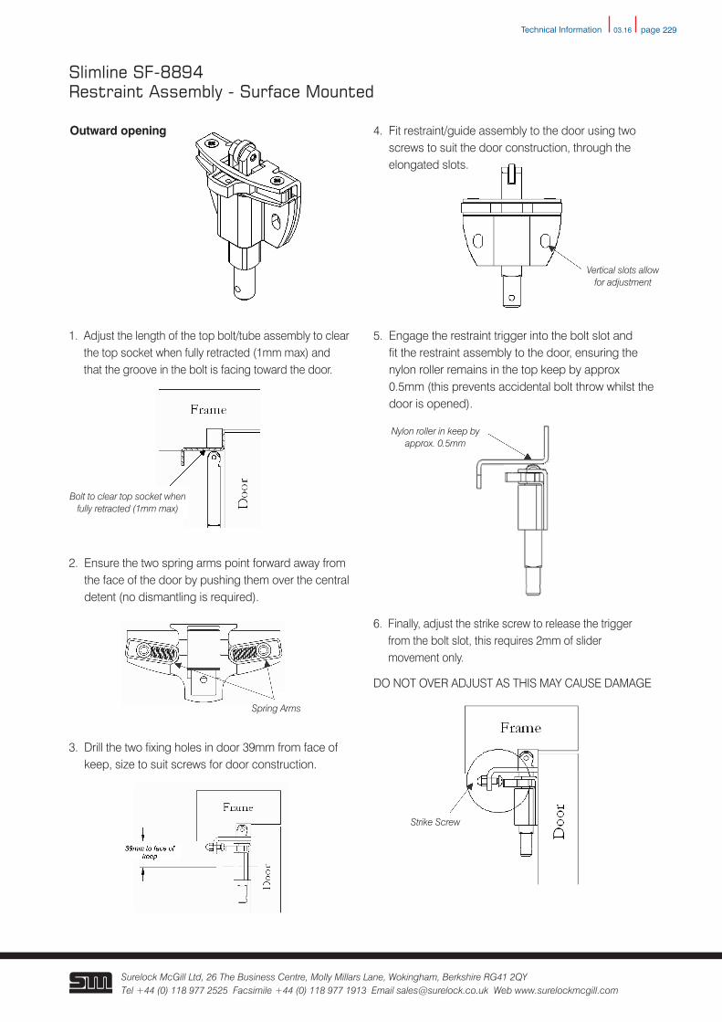
Outward opening
1. Adjust the length of the top bolt/tube assembly to clear the top socket when fully retracted (1mm max) and that the groove in the bolt is facing toward the door.
5. Engage the restraint trigger into the bolt slot and fit the restraint assembly to the door, ensuring the nylon roller remains in the top keep by approx 0.5mm (this prevents accidental bolt throw whilst the door is opened).
2. Ensure the two spring arms point forward away from the face of the door by pushing them over the central detent (no dismantling is required).
3. Drill the two fixing holes in door 39mm from face of keep, size to suit screws for door construction.
4. Fit restraint/guide assembly to the door using two screws to suit the door construction, through the elongated slots.
6. Finally, adjust the strike screw to release the trigger from the bolt slot, this requires 2mm of slider movement only.
DO NOT OVER ADJUST AS THIS MAY CAUSE DAMAGE
Slimline SF-8894Restraint Assembly - Surface Mounted
Spring Arms
Vertical slots allow for adjustment
Nylon roller in keep by approx. 0.5mm
Strike Screw
Bolt to clear top socket when fully retracted (1mm max)
Technical Information
03.16 page 230
Surelock McGill Ltd, 26 The Business Centre, Molly Millars Lane, Wokingham, Berkshire RG41 2QY Tel +44 (0) 118 977 2525 Facsimile +44 (0) 118 977 1913 Email [email protected] Web www.surelockmcgill.com
Nylon roller in keep by approx. 0.5mm
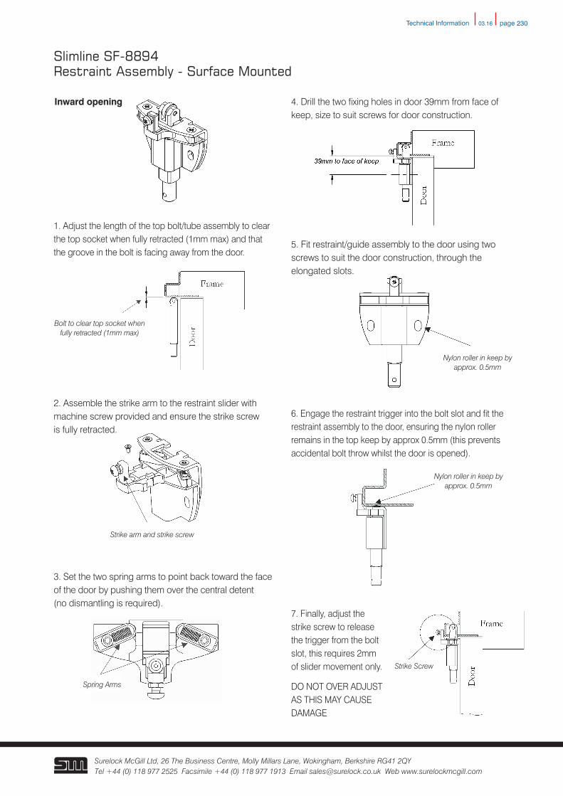
Inward opening
5. Fit restraint/guide assembly to the door using two screws to suit the door construction, through the elongated slots.
Strike arm and strike screw
2. Assemble the strike arm to the restraint slider with machine screw provided and ensure the strike screw is fully retracted.
4. Drill the two fixing holes in door 39mm from face of keep, size to suit screws for door construction.
6. Engage the restraint trigger into the bolt slot and fit the restraint assembly to the door, ensuring the nylon roller remains in the top keep by approx 0.5mm (this prevents accidental bolt throw whilst the door is opened).
Slimline SF-8894Restraint Assembly - Surface Mounted
Spring Arms
3. Set the two spring arms to point back toward the face of the door by pushing them over the central detent (no dismantling is required).
Nylon roller in keep by approx. 0.5mm
1. Adjust the length of the top bolt/tube assembly to clear the top socket when fully retracted (1mm max) and that the groove in the bolt is facing away from the door.
Bolt to clear top socket when fully retracted (1mm max)
7. Finally, adjust the strike screw to release the trigger from the bolt slot, this requires 2mm of slider movement only.
DO NOT OVER ADJUST AS THIS MAY CAUSE DAMAGE
Strike Screw
Technical Information
03.16 page 231
Surelock McGill Ltd, 26 The Business Centre, Molly Millars Lane, Wokingham, Berkshire RG41 2QY Tel +44 (0) 118 977 2525 Facsimile +44 (0) 118 977 1913 Email [email protected] Web www.surelockmcgill.com
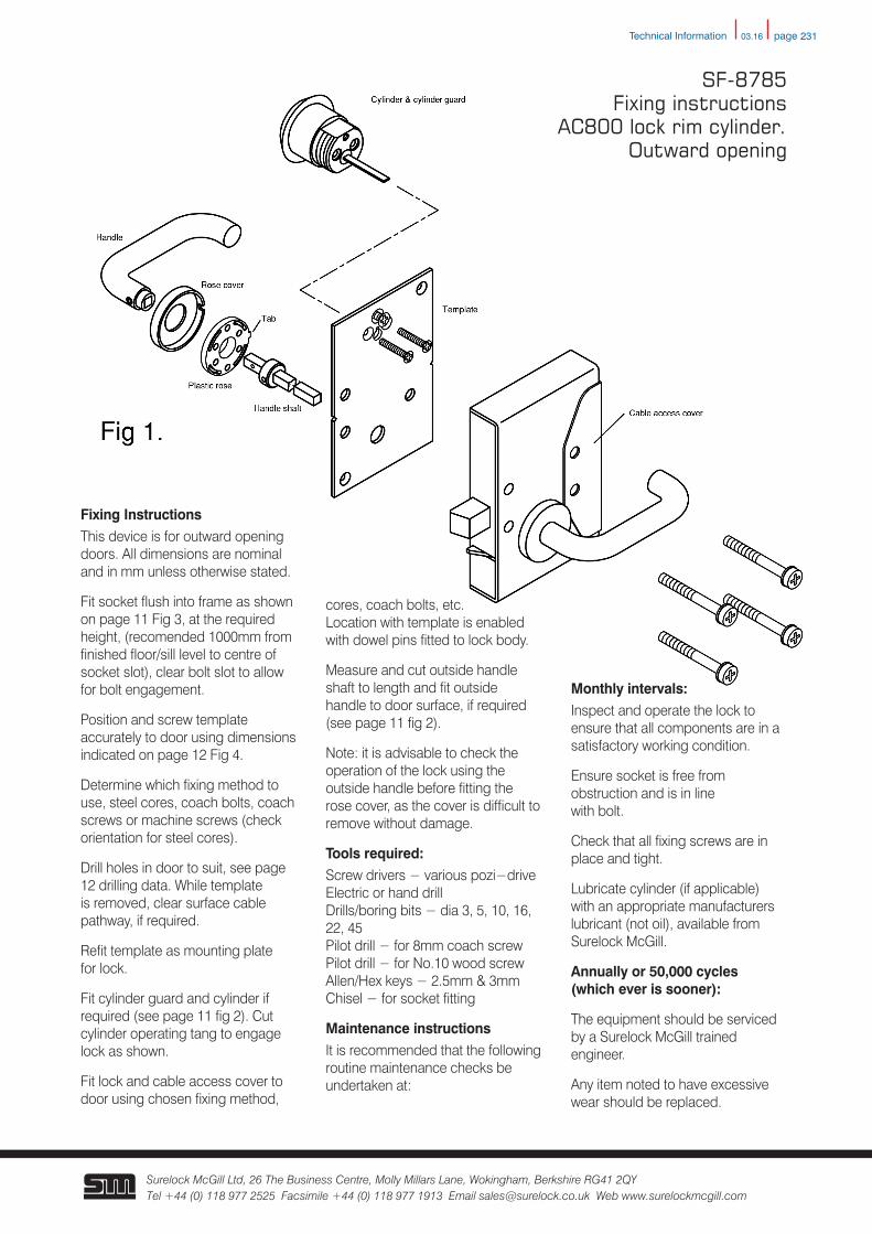
Fixing InstructionsThis device is for outward opening doors. All dimensions are nominal and in mm unless otherwise stated.
Fit socket flush into frame as shown on page 11 Fig 3, at the required height, (recomended 1000mm from finished floor/sill level to centre of socket slot), clear bolt slot to allow for bolt engagement.
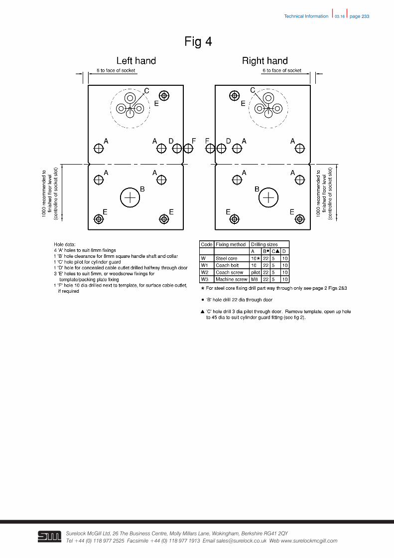
Position and screw template accurately to door using dimensions indicated on page 12 Fig 4.
Determine which fixing method to use, steel cores, coach bolts, coach screws or machine screws (check orientation for steel cores).
Drill holes in door to suit, see page 12 drilling data. While template is removed, clear surface cable pathway, if required.
Refit template as mounting plate for lock.
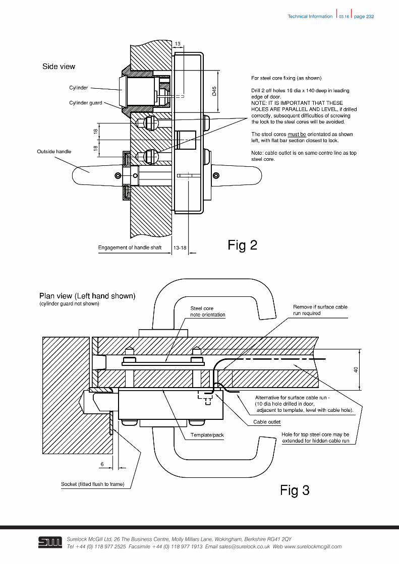
Fit cylinder guard and cylinder if required (see page 11 fig 2). Cut cylinder operating tang to engage lock as shown.
Fit lock and cable access cover to door using chosen fixing method,
cores, coach bolts, etc. Location with template is enabled with dowel pins fitted to lock body.
Measure and cut outside handle shaft to length and fit outside handle to door surface, if required (see page 11 fig 2).
Note: it is advisable to check the operation of the lock using the outside handle before fitting the rose cover, as the cover is difficult to remove without damage.
Tools required:Screw drivers − various pozi−drive Electric or hand drill Drills/boring bits − dia 3, 5, 10, 16, 22, 45 Pilot drill − for 8mm coach screw Pilot drill − for No.10 wood screw Allen/Hex keys − 2.5mm & 3mm Chisel − for socket fitting
Maintenance instructionsIt is recommended that the following routine maintenance checks be undertaken at:
Monthly intervals:Inspect and operate the lock to ensure that all components are in a satisfactory working condition.
Ensure socket is free from obstruction and is in line with bolt.
Check that all fixing screws are in place and tight.
Lubricate cylinder (if applicable) with an appropriate manufacturers lubricant (not oil), available from Surelock McGill.
Annually or 50,000 cycles (which ever is sooner):
The equipment should be serviced by a Surelock McGill trained engineer.
Any item noted to have excessive wear should be replaced.
SF-8785 Fixing instructions
AC800 lock rim cylinder. Outward opening
Technical Information
03.16 page 232
Surelock McGill Ltd, 26 The Business Centre, Molly Millars Lane, Wokingham, Berkshire RG41 2QY Tel +44 (0) 118 977 2525 Facsimile +44 (0) 118 977 1913 Email [email protected] Web www.surelockmcgill.com
Technical Information
03.16 page 233
Surelock McGill Ltd, 26 The Business Centre, Molly Millars Lane, Wokingham, Berkshire RG41 2QY Tel +44 (0) 118 977 2525 Facsimile +44 (0) 118 977 1913 Email [email protected] Web www.surelockmcgill.com
Technical Information
03.16 page 234
Surelock McGill Ltd, 26 The Business Centre, Molly Millars Lane, Wokingham, Berkshire RG41 2QY Tel +44 (0) 118 977 2525 Facsimile +44 (0) 118 977 1913 Email [email protected] Web www.surelockmcgill.com
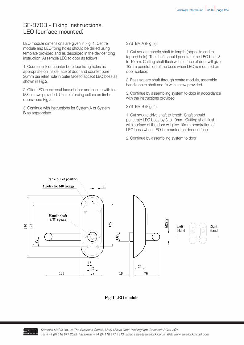
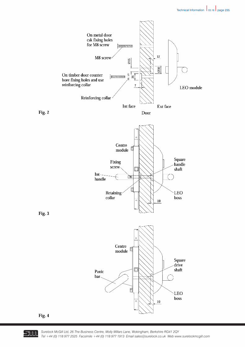
LEO module dimensions are given in Fig. 1. Centre module and LEO fixing holes should be drilled using template provided and as described in the device fixing instruction. Assemble LEO to door as follows.
1. Countersink or counter bore four fixing holes as appropriate on inside face of door and counter bore 30mm dia relief hole in outer face to accept LEO boss as shown in Fig.2.
2. Offer LEO to external face of door and secure with four M8 screws provided. Use reinforcing collars on timber doors - see Fig.2.
3. Continue with instructions for System A or System B as appropriate.
SYSTEM A (Fig. 3)
1. Cut square handle shaft to length (opposite end to tapped hole). The shaft should penetrate the LEO boss 8 to 10mm. Cutting shaft flush with surface of door will give 10mm penetration of the boss when LEO is mounted on door surface.
2. Pass square shaft through centre module, assemble handle on to shaft and fix with screw provided.
3. Continue by assembling system to door in accordance with the instructions provided.
SYSTEM B (Fig. 4)
1. Cut square drive shaft to length. Shaft should penetrate LEO boss by 8 to 10mm. Cutting shaft flush with surface of the door will give 10mm penetration of LEO boss when LEO is mounted on door surface.
2. Continue by assembling system to door
SF-8703 - Fixing instructions.LEO (surface mounted)
Technical Information
03.16 page 235
Surelock McGill Ltd, 26 The Business Centre, Molly Millars Lane, Wokingham, Berkshire RG41 2QY Tel +44 (0) 118 977 2525 Facsimile +44 (0) 118 977 1913 Email [email protected] Web www.surelockmcgill.com
Technical Information
03.16 page 236
Surelock McGill Ltd, 26 The Business Centre, Molly Millars Lane, Wokingham, Berkshire RG41 2QY Tel +44 (0) 118 977 2525 Facsimile +44 (0) 118 977 1913 Email [email protected] Web www.surelockmcgill.com
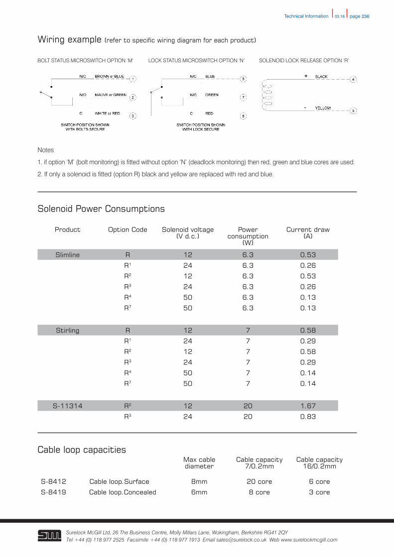
Wiring example (refer to specific wiring diagram for each product)
BOLT STATUS MICROSWITCH OPTION ‘M’ LOCK STATUS MICROSWITCH OPTION ‘N’ SOLENOID LOCK RELEASE OPTION ‘R’
Notes
1. if option ‘M’ (bolt monitoring) is fitted without option ‘N’ (deadlock monitoring) then red, green and blue cores are used.
2. If only a solenoid is fitted (option R) black and yellow are replaced with red and blue.
Solenoid Power Consumptions
Product Option Code Solenoid voltage (V d.c.)
Power consumption
(W)
Current draw(A)
Slimline R 12 6.3 0.53
R1 24 6.3 0.26
R2 12 6.3 0.53
R3 24 6.3 0.26
R4 50 6.3 0.13
R7 50 6.3 0.13
Stirling R 12 7 0.58
R1 24 7 0.29
R2 12 7 0.58
R3 24 7 0.29
R4 50 7 0.14
R7 50 7 0.14
S-11314 R2 12 20 1.67
R3 24 20 0.83
Cable loop capacitiesMax cablediameter
Cable capacity7/0.2mm
Cable capacity16/0.2mm
S-8412 Cable loop.Surface 8mm 20 core 6 core
S-8419 Cable loop.Concealed 6mm 8 core 3 core
Technical Information
03.16 page 237
Surelock McGill Ltd, 26 The Business Centre, Molly Millars Lane, Wokingham, Berkshire RG41 2QY Tel +44 (0) 118 977 2525 Facsimile +44 (0) 118 977 1913 Email [email protected] Web www.surelockmcgill.com
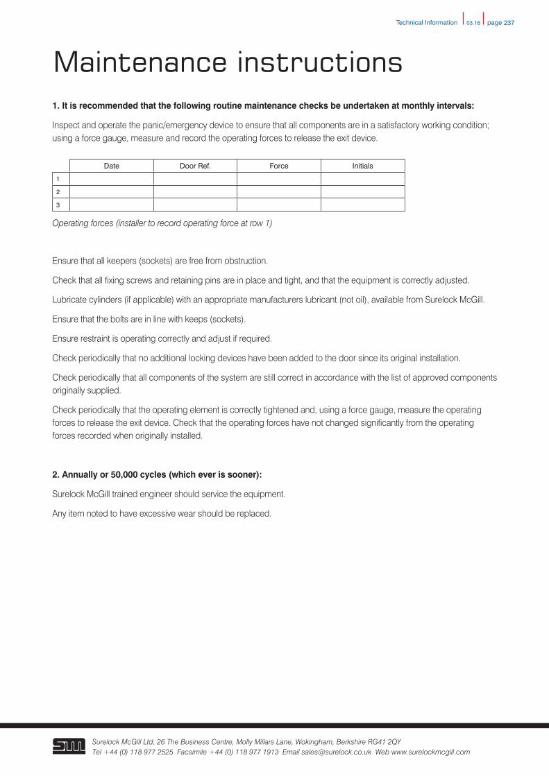
Maintenance instructions1. It is recommended that the following routine maintenance checks be undertaken at monthly intervals:
Inspect and operate the panic/emergency device to ensure that all components are in a satisfactory working condition; using a force gauge, measure and record the operating forces to release the exit device.
Ensure that all keepers (sockets) are free from obstruction.
Check that all fixing screws and retaining pins are in place and tight, and that the equipment is correctly adjusted.
Lubricate cylinders (if applicable) with an appropriate manufacturers lubricant (not oil), available from Surelock McGill.
Ensure that the bolts are in line with keeps (sockets).
Ensure restraint is operating correctly and adjust if required.
Check periodically that no additional locking devices have been added to the door since its original installation.
Check periodically that all components of the system are still correct in accordance with the list of approved components originally supplied.
Check periodically that the operating element is correctly tightened and, using a force gauge, measure the operating forces to release the exit device. Check that the operating forces have not changed significantly from the operating forces recorded when originally installed.
2. Annually or 50,000 cycles (which ever is sooner):
Surelock McGill trained engineer should service the equipment.
Any item noted to have excessive wear should be replaced.
Date Door Ref. Force Initials
1
2
3
Operating forces (installer to record operating force at row 1)
Technical Information
03.16 page 238
Surelock McGill Ltd, 26 The Business Centre, Molly Millars Lane, Wokingham, Berkshire RG41 2QY Tel +44 (0) 118 977 2525 Facsimile +44 (0) 118 977 1913 Email [email protected] Web www.surelockmcgill.com
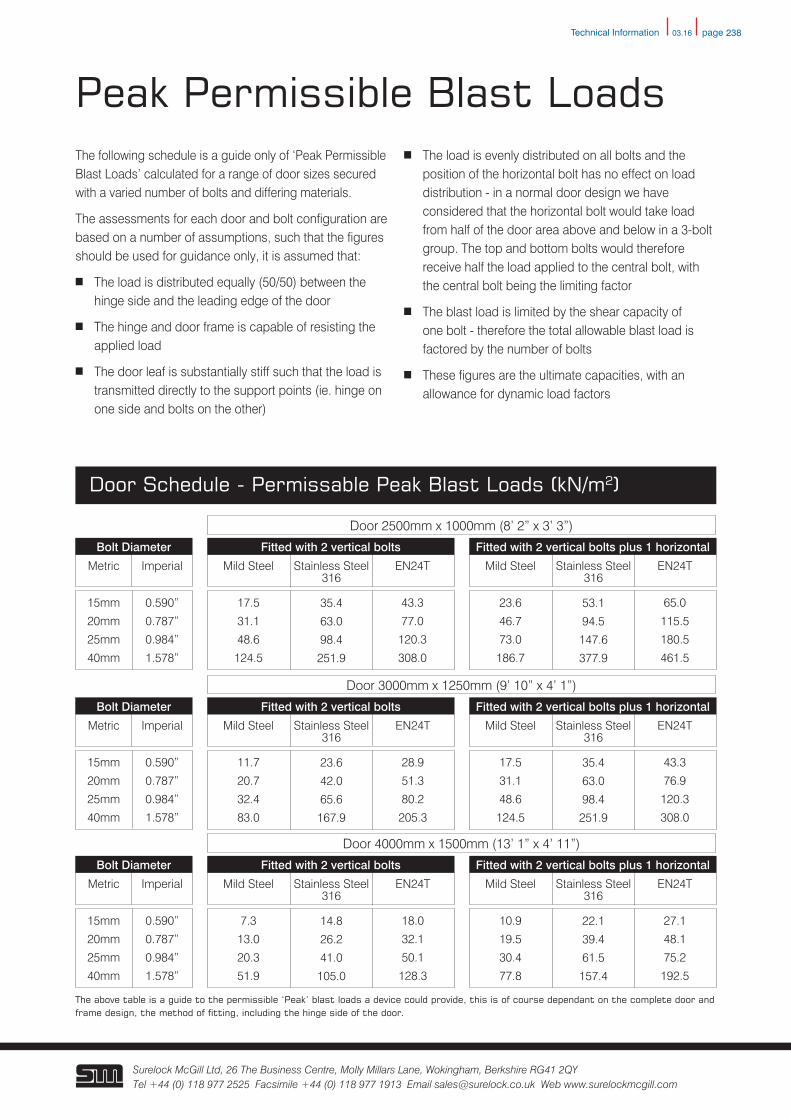
Peak Permissible Blast LoadsThe following schedule is a guide only of ‘Peak Permissible Blast Loads’ calculated for a range of door sizes secured with a varied number of bolts and differing materials.
The assessments for each door and bolt configuration are based on a number of assumptions, such that the figures should be used for guidance only, it is assumed that:
n The load is distributed equally (50/50) between the hinge side and the leading edge of the door
n The hinge and door frame is capable of resisting the applied load
n The door leaf is substantially stiff such that the load is transmitted directly to the support points (ie. hinge on one side and bolts on the other)
n The load is evenly distributed on all bolts and the position of the horizontal bolt has no effect on load distribution - in a normal door design we have considered that the horizontal bolt would take load from half of the door area above and below in a 3-bolt group. The top and bottom bolts would therefore receive half the load applied to the central bolt, with the central bolt being the limiting factor
n The blast load is limited by the shear capacity of one bolt - therefore the total allowable blast load is factored by the number of bolts
n These figures are the ultimate capacities, with an allowance for dynamic load factors
Door Schedule - Permissable Peak Blast Loads (kN/m2)
Metric
15mm
20mm
25mm
40mm
Imperial
0.590”
0.787”
0.984”
1.578”
Bolt Diameter
Mild Steel
17.5
31.1
48.6
124.5
Stainless Steel 316
35.4
63.0
98.4
251.9
EN24T
43.3
77.0
120.3
308.0
Fitted with 2 vertical bolts
Mild Steel
23.6
46.7
73.0
186.7
Stainless Steel 316
53.1
94.5
147.6
377.9
EN24T
65.0
115.5
180.5
461.5
Fitted with 2 vertical bolts plus 1 horizontal
Metric
15mm
20mm
25mm
40mm
Imperial
0.590”
0.787”
0.984”
1.578”
Bolt Diameter
Mild Steel
11.7
20.7
32.4
83.0
Stainless Steel 316
23.6
42.0
65.6
167.9
EN24T
28.9
51.3
80.2
205.3
Fitted with 2 vertical bolts
Mild Steel
17.5
31.1
48.6
124.5
Stainless Steel 316
35.4
63.0
98.4
251.9
EN24T
43.3
76.9
120.3
308.0
Fitted with 2 vertical bolts plus 1 horizontal
Metric
15mm
20mm
25mm
40mm
Imperial
0.590”
0.787”
0.984”
1.578”
Bolt Diameter
Mild Steel
7.3
13.0
20.3
51.9
Stainless Steel 316
14.8
26.2
41.0
105.0
EN24T
18.0
32.1
50.1
128.3
Fitted with 2 vertical bolts
Mild Steel
10.9
19.5
30.4
77.8
Stainless Steel 316
22.1
39.4
61.5
157.4
EN24T
27.1
48.1
75.2
192.5
Fitted with 2 vertical bolts plus 1 horizontal
The above table is a guide to the permissible ‘Peak’ blast loads a device could provide, this is of course dependant on the complete door and frame design, the method of fitting, including the hinge side of the door.
Door 2500mm x 1000mm (8’ 2” x 3’ 3”)
Door 3000mm x 1250mm (9’ 10” x 4’ 1”)
Door 4000mm x 1500mm (13’ 1” x 4’ 11”)
Technical Information
03.16 page 239
Surelock McGill Ltd, 26 The Business Centre, Molly Millars Lane, Wokingham, Berkshire RG41 2QY Tel +44 (0) 118 977 2525 Facsimile +44 (0) 118 977 1913 Email [email protected] Web www.surelockmcgill.com
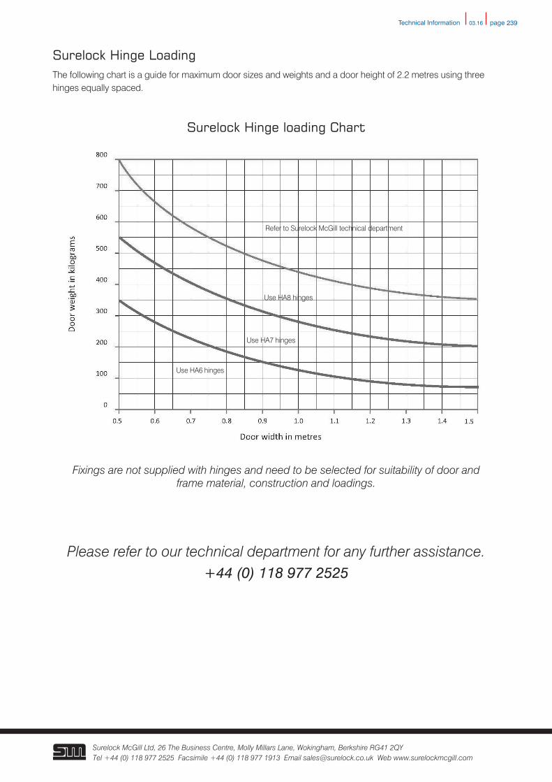
Surelock Hinge LoadingThe following chart is a guide for maximum door sizes and weights and a door height of 2.2 metres using three hinges equally spaced.
Surelock Hinge loading Chart
Fixings are not supplied with hinges and need to be selected for suitability of door andframe material, construction and loadings.
Please refer to our technical department for any further assistance.+44 (0) 118 977 2525
Refer to Surelock McGill technical department
Use HA8 hinges
Use HA7 hinges
Use HA6 hinges
Technical Information


![030 /0.75mm - No Gap · ershire Hathaway Company RMF 111416 W ]}µ D o ^}oµ }v W }À] Imaes ae a acal sie HOOPS Fashion - Lever Hoops 12mm 12mm 12mm 14KY 143112-TL 143112-D1 143112-D1-GR](https://img.pdfslide.us/doc/110x75/5eba03009d8a8539f72a1537/030-075mm-no-ershire-hathaway-company-rmf-111416-w-d-o-o-v-w-.jpg)
![LOW PRESSURE FILTERS NF MMP Series - hydac-na.com · D182 PN#02081318 / 03.16 / FIL1505-1696 LOW PRESSURE FILTERS Size 5210 Weight (lbs.) 287 Dimensions shown are [inches] millimeters](https://img.pdfslide.us/doc/110x75/5bef866409d3f2ec148b8ff2/low-pressure-filters-nf-mmp-series-hydac-na-d182-pn02081318-0316-fil1505-1696.jpg)