Embed Size (px)
Citation preview
Products Solutions ServicesTI01005G/08/EN/03.14
71264163
Technical InformationProthermo NMT539Intrinsically Safe Multi-signal Converter with Precision Average Temperatureand Water Bottom Sensor for Inventory Control and Custody Transfer Applications
ApplicationProthermo NMT 539 is based on API (American Petroleum Institute) Manual of Petro-leum Measurement Standard, Chapter 7, and enables high accuracy temperature mea-surement. At the same time, it is an intelligent average temperature sensor for tank gauging with an optional WB capacitance sensor at the bottom of the temperature probe. For average temperature measurement, it consists of precision multi-spot Pt100 ele-ments. NMT539 is a highly capable solution that provides both constant average temperature data and water interface data via local HART communication. For accurate inventory measurement, it is best suited connected to Endress+Hauser’s Proservo NMS5/NMS7 or Tank Side Monitor NRF590 with Micropilot radar.
Features and Benefits• Intrinsically safe device allowing for the safest electrical configuration possible• Available in three different versions based on customer requirements:
– Converter Only
– Converter and Temperature probe
– Converter, temperature and water bottom (WB) probe• Converter is compatible with various element types in third party manufacturer
temperature probes. • Variety of process connections and cable entries available to meet worldwide classi-
fications.
Prothermo NMT539
2 Endress+Hauser
Table of Contents
Important Document Information. . . . . . . . . . . . . . . . . . . . . 4Notes on Safety Conventions and Symbols . . . . . . . . . . . . . . . . 4
Function and System Design . . . . . . . . . . . . . . . . . . . . . . . . . .5System Design . . . . . . . . . . . . . . . . . . . . . . . . . . . . . . . . . . . . . . . . 5System Design 2 . . . . . . . . . . . . . . . . . . . . . . . . . . . . . . . . . . . . . . . .6NMT539 Ex ia and NMS5 Ex d [ia] Combination . . . . . . . . . . . 7NMT 539 Converter + Temp. Probe Version . . . . . . . . . . . . . . . 7NMT539 Ex ia and NRF590 Ex d [ia] Combination . . . . . . . . . .8NMT 539 Converter + Temp. + WB version . . . . . . . . . . . . . . . . 8NMT539 Ex d [ia] and TMD1 Combination . . . . . . . . . . . . . . . . 9NMT539 Ex d [ia] and TGM5 or NMS5 Combination . . . . . . . 9NMT539 TIIS Ex ia (High Temp.) and NMS5 Ex d Combination . . . . . . . . . . . . . . . . . . . . . . . . . . . . . . . 10Installation to Fixed Roof Tank . . . . . . . . . . . . . . . . . . . . . . . . . 10Installation to Floating Roof Tank 1 . . . . . . . . . . . . . . . . . . . . . 11Installation to Floating Roof Tank 2 . . . . . . . . . . . . . . . . . . . . . 11Installation to Floating Roof Tank 3 . . . . . . . . . . . . . . . . . . . . . 12Application for Pressurized Tank . . . . . . . . . . . . . . . . . . . . . . . 13
Input and Output . . . . . . . . . . . . . . . . . . . . . . . . . . . . . . . . . . 14Measured Variables . . . . . . . . . . . . . . . . . . . . . . . . . . . . . . . . . . . 14Compatible Element (Converter Only Version) . . . . . . . . . . . . 14Number of Elements . . . . . . . . . . . . . . . . . . . . . . . . . . . . . . . . . . 14Communication . . . . . . . . . . . . . . . . . . . . . . . . . . . . . . . . . . . . . . 14Alarm Signal . . . . . . . . . . . . . . . . . . . . . . . . . . . . . . . . . . . . . . . . . 14Output Signal . . . . . . . . . . . . . . . . . . . . . . . . . . . . . . . . . . . . . . . . 14Connection . . . . . . . . . . . . . . . . . . . . . . . . . . . . . . . . . . . . . . . . . . 14
Auxiliary Energy . . . . . . . . . . . . . . . . . . . . . . . . . . . . . . . . . . 15Load HART . . . . . . . . . . . . . . . . . . . . . . . . . . . . . . . . . . . . . . . . . . 15Overvoltage Protection . . . . . . . . . . . . . . . . . . . . . . . . . . . . . . . . 15Supply Voltage . . . . . . . . . . . . . . . . . . . . . . . . . . . . . . . . . . . . . . . 15Power Consumption . . . . . . . . . . . . . . . . . . . . . . . . . . . . . . . . . . 15
Performance Characteristics . . . . . . . . . . . . . . . . . . . . . . . . 16Temperature Accuracy . . . . . . . . . . . . . . . . . . . . . . . . . . . . . . . . 16WB Accuracy . . . . . . . . . . . . . . . . . . . . . . . . . . . . . . . . . . . . . . . . 16Reference Operating Conditions . . . . . . . . . . . . . . . . . . . . . . . . 16Maximum Measured Error . . . . . . . . . . . . . . . . . . . . . . . . . . . . . 16New Module . . . . . . . . . . . . . . . . . . . . . . . . . . . . . . . . . . . . . . . . . 16All-in-one Program . . . . . . . . . . . . . . . . . . . . . . . . . . . . . . . . . . . 16
Operating Condition: Environment and Process . . . . . . . . . 17
Ambient Temperature Range . . . . . . . . . . . . . . . . . . . . . . . . . . 17Storage Temperature . . . . . . . . . . . . . . . . . . . . . . . . . . . . . . . . . 17Climate Class . . . . . . . . . . . . . . . . . . . . . . . . . . . . . . . . . . . . . . . . 17Degree of Protection . . . . . . . . . . . . . . . . . . . . . . . . . . . . . . . . . . 17Electromagnetic Compatibility . . . . . . . . . . . . . . . . . . . . . . . . . . 17Process temperature Range . . . . . . . . . . . . . . . . . . . . . . . . . . . . 17Process Pressure Limits . . . . . . . . . . . . . . . . . . . . . . . . . . . . . . . 17Data Transmission . . . . . . . . . . . . . . . . . . . . . . . . . . . . . . . . . . . . 17
Operating Condition: Installation . . . . . . . . . . . . . . . . . . . . 18Cable Grands . . . . . . . . . . . . . . . . . . . . . . . . . . . . . . . . . . . . . . . . 18Process Connection . . . . . . . . . . . . . . . . . . . . . . . . . . . . . . . . . . . 18Height Adjustment for NMT539 . . . . . . . . . . . . . . . . . . . . . . . . 18WB Blocking Distance . . . . . . . . . . . . . . . . . . . . . . . . . . . . . . . . . 18Recommended Installation Height . . . . . . . . . . . . . . . . . . . . . . 19Recommended Stilling Well Installation . . . . . . . . . . . . . . . . . . 20Installation Equipment . . . . . . . . . . . . . . . . . . . . . . . . . . . . . . . . 20Mounting Attachment -1 . . . . . . . . . . . . . . . . . . . . . . . . . . . . . . 21Mounting Attachment-2 . . . . . . . . . . . . . . . . . . . . . . . . . . . . . . 22#1 Element Position of NMT539 . . . . . . . . . . . . . . . . . . . . . . . 23Anchor Weight Method . . . . . . . . . . . . . . . . . . . . . . . . . . . . . . . 23
Operating Condition: Wiring . . . . . . . . . . . . . . . . . . . . . . . . 24TIIS Ex d [ia] Wiring . . . . . . . . . . . . . . . . . . . . . . . . . . . . . . . . . . 24Grounding Cable Construction (TIIS Ex d [ia]) . . . . . . . . . . . . . 24Connecting Diagram (TIIS Ex d [ia]) . . . . . . . . . . . . . . . . . . . . . 25
Operating Condition: Terminal Connection . . . . . . . . . . . 26Ex ia NMT539 Terminal . . . . . . . . . . . . . . . . . . . . . . . . . . . . . . . 26ATEX, FM, CSA, Ex d [ia] NMS5 Terminal . . . . . . . . . . . . . . . . 26TIIS Ex d [ia] NMT539 Terminal . . . . . . . . . . . . . . . . . . . . . . . . 27Ex d NMS5 Connection . . . . . . . . . . . . . . . . . . . . . . . . . . . . . . . . 27TGM5/TMD1 Terminal . . . . . . . . . . . . . . . . . . . . . . . . . . . . . . . . 28Terminal Connection of NRF590 . . . . . . . . . . . . . . . . . . . . . . . . 28
3 Endress+Hauser
Prothermo NMT539
Table of Contents
Mechanical Construction . . . . . . . . . . . . . . . . . . . . . . . . . . . 29Type 1: Converter Only Version . . . . . . . . . . . . . . . . . . . . . . . . . 29Type 1: Measuring Function . . . . . . . . . . . . . . . . . . . . . . . . . . . . 29Type 1: Converter Only Version . . . . . . . . . . . . . . . . . . . . . . . . . 30Type 2: Measuring Function . . . . . . . . . . . . . . . . . . . . . . . . . . . . 30Converter + Average Temperature Probe Version . . . . . . . . . . 30Measuring Function . . . . . . . . . . . . . . . . . . . . . . . . . . . . . . . . . . . 31W&M Function . . . . . . . . . . . . . . . . . . . . . . . . . . . . . . . . . . . . . . . 31Converter + Average Temperature Probe + WB Probe Version 32Measuring Function . . . . . . . . . . . . . . . . . . . . . . . . . . . . . . . . . . . 32WB Probe Design . . . . . . . . . . . . . . . . . . . . . . . . . . . . . . . . . . . . . 33Welding Flange Type . . . . . . . . . . . . . . . . . . . . . . . . . . . . . . . . . . 33Protective Cover for TIIS Exd [ia] . . . . . . . . . . . . . . . . . . . . . . . . 34Weight . . . . . . . . . . . . . . . . . . . . . . . . . . . . . . . . . . . . . . . . . . . . . . 34Material . . . . . . . . . . . . . . . . . . . . . . . . . . . . . . . . . . . . . . . . . . . . . 34
Human Interface . . . . . . . . . . . . . . . . . . . . . . . . . . . . . . . . . . 35Operation Using FieldCare . . . . . . . . . . . . . . . . . . . . . . . . . . . . . 35
Certificates and Approvals. . . . . . . . . . . . . . . . . . . . . . . . . . 36CE Mark . . . . . . . . . . . . . . . . . . . . . . . . . . . . . . . . . . . . . . . . . . . . . 36Ex Approvals . . . . . . . . . . . . . . . . . . . . . . . . . . . . . . . . . . . . . . . . . 36PTB W&M Approval . . . . . . . . . . . . . . . . . . . . . . . . . . . . . . . . . . 36External Standards and Guidelines . . . . . . . . . . . . . . . . . . . . . . 36
Order Information . . . . . . . . . . . . . . . . . . . . . . . . . . . . . . . . .37
Accessories . . . . . . . . . . . . . . . . . . . . . . . . . . . . . . . . . . . . . . .39Anchor Weight (High Profile, D120) . . . . . . . . . . . . . . . . . . . . 39Anchor Weight (Low Profile, Hexagon H41) . . . . . . . . . . . . . . 39Wire Hook, Top Anchor . . . . . . . . . . . . . . . . . . . . . . . . . . . . . . . 40
Documentation . . . . . . . . . . . . . . . . . . . . . . . . . . . . . . . . . . . .41Technical Information . . . . . . . . . . . . . . . . . . . . . . . . . . . . . . . . . 41Operating Instructions . . . . . . . . . . . . . . . . . . . . . . . . . . . . . . . . . 41Certificates . . . . . . . . . . . . . . . . . . . . . . . . . . . . . . . . . . . . . . . . . . 41
Appendix. . . . . . . . . . . . . . . . . . . . . . . . . . . . . . . . . . . . . . . . . 42Stainless Steel Conversion Table . . . . . . . . . . . . . . . . . . . . . . . . 42
Prothermo NMT539
4 Endress+Hauser
Important Document Information
Notes on Safety Conventions and Symbols
Symbols for Safety Conventions
Symbols for Certain Types of Information
Symbol Meaning
A0011189-EN
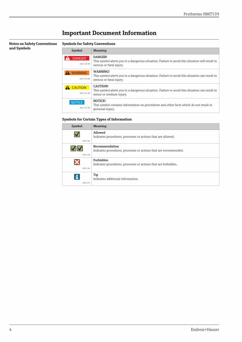
DANGER!This symbol alerts you to a dangerous situation. Failure to avoid this situation will result in serious or fatal injury.
A0011190-EN
WARNING!This symbol alerts you to a dangerous situation. Failure to avoid this situation can result in serious or fatal injury.
A0011191-EN
CAUTION!This symbol alerts you to a dangerous situation. Failure to avoid this situation can result in minor or medium injury.
A0011192-EN
NOTICE!This symbol contains information on procedures and other facts which do not result in personal injury.
Symbol Meaning
A0011182
AllowedIndicates procedures, processes or actions that are allowed.
A0011183
RecommendationIndicates procedures, processes or actions that are recommended.
A0011184
ForbiddenIndicates procedures, processes or actions that are forbidden.
A0011193
TipIndicates additional information.
DANGER
WARNING
CAUTION
NOTICE

Prothermo NMT539
Endress+Hauser 5
Function and System Design
System Design NMT 539 is available in three different versions:• Converter Only• Converter + Average Temperature Probe• Converter + Average Temp Probe + Water Bottom Probe
The converter only version can be retrofitted without modifications onto existing third party average temperature probes, such as Whessoe Varec 9909 and 1700 and Weed Beacon MW type probes. The average temperature probe + converter inherits all the functionality of the former NMT 535/536/537 series. The average temperature + WB + converter is the ultimate multi-function sensor, transmitting temperature and water interface level data along only one pair of local HART signal cables to the host NMS5, Servo gauge TGM5, Digital Transmitter TMD1or Tank Side Monitor NRF 590.
NMT 539 + WB Operation Principle (Converter + Temp + WB probe version)
Figure 1: NRF560 System Configuration
Each type of NMT 539 including converter only or converter + average temperature are simplified ver-sions for combination of converter + average temperature probe + WB (Water Bottom) Probe.
Local HART Communication Noise Filter
Power Supply Module
C/F Module
CPU Module
WB Sensor Signal FG
Isolated Capacitance Signal Data to
C/F Module
WB Sensor CoaxialSignal Cable
Max. 2 Pt100 elementscan be inserted in
WB sensor.
Capacitance WB Sensor
Liquid
Gas
Pt100 Multi-spot ElementsUp to 16 Points
Converter Housing
360mm AdjustableThreaded Connection
Flange
NOTICE
Prothermo NMT539
6 Endress+Hauser
System Design 2
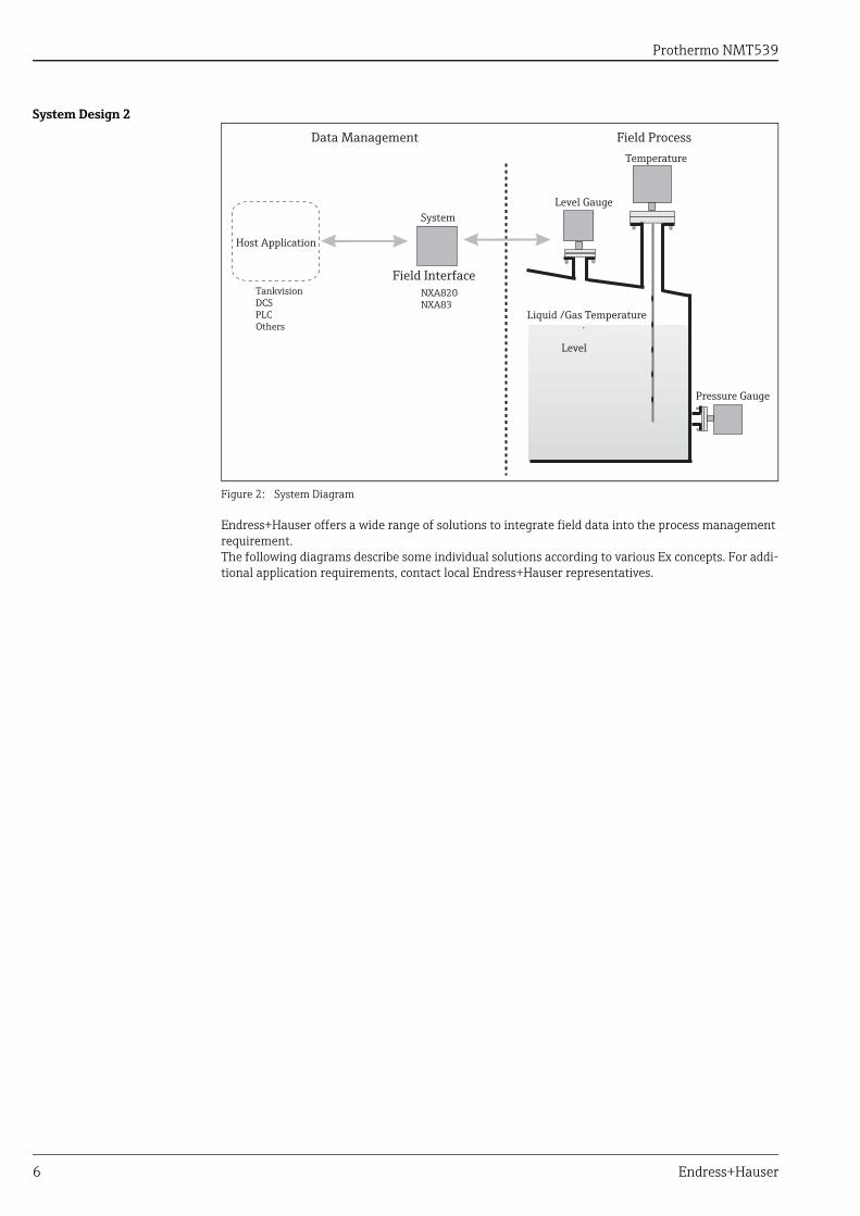
Figure 2: System Diagram
Endress+Hauser offers a wide range of solutions to integrate field data into the process management requirement.The following diagrams describe some individual solutions according to various Ex concepts. For addi-tional application requirements, contact local Endress+Hauser representatives.
Host Application
System
Data Management
Field Interface
Field ProcessTemperature
Level Gauge
Pressure Gauge
Liquid /Gas Temperature
Level
TankvisionDCSPLCOthers
NXA820NXA83
Prothermo NMT539
Endress+Hauser 7
NMT539 Ex ia and NMS5 Ex d [ia] Combination
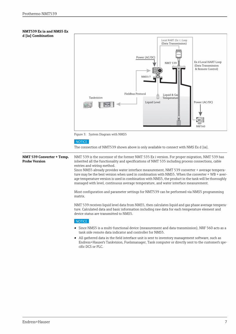
Figure 3: System Diagram with NMS5
The connection of NMT539 shown above is only available to connect with NMS Ex d [ia].
NMT 539 Converter + Temp. Probe Version
NMT 539 is the successor of the former NMT 535 Ex i version. For proper migration, NMT 539 has inherited all the functionality and specifications of NMT 535 including process connections, cable entries and wiring method.Since NMS5 already provides water interface measurement, NMT 539 converter + average tempera-ture may be the best version when used in combination with NMS5. When the converter + WB + aver-age temperature version is used in combination with NMS5, the product in the tank will be thoroughly managed with level, continuous average temperature, and water interface measurement.
Most configuration and parameter settings for NMT539 can be performed via NMS5 programming matrix.
NMT 539 receives liquid level data from NMS5, then calculates liquid and gas phase average tempera-ture. Calculated data and basic information including raw data for each temperature element and device status are transmitted to NMS5.
• Since NMS5 is a multi-functional device (measurement and data transmission), NRF 560 acts as a tank side remote data indicator and controller for NMS5.
• All gathered data in the field interface unit is sent to inventory management software, such as Endress+Hauser's Tankvision, Fuelsmanager, Tank computer or directly sent to the customer's spe-cific DCS or PLC.
Liquid Level Power (AC/DC)
NMS5/7
NRF560
Local HART (Ex i ) Loop(Data Transmission)
Liquid & GasTemperature
NMT 539
Fieldbus Protocol
Power (AC/DC)Ex d Local HART Loop
(Data Transmission & Remote Control)
Tankvisionsion
NOTICE
NOTICE

Prothermo NMT539
8 Endress+Hauser
NMT539 Ex ia and NRF590 Ex d [ia] Combination
Figure 4: System Diagram with NRF590
NMT 539 Converter + Temp. + WB version
NMT 539 Converter + Temp. + WB is utilized effectively in combination with radar level gauging. Water interface, temperature and level measurement, with data collection and calculations via the NRF 590, allow for optimal inventory control. Basic functionality of NMT 539 is displayed and configured on NRF 590. Detailed NMT 539 functionality and data access can be performed by FieldCare.
NMT 539 receives radar level data from the NRF 590 and then calculates liquid and gas phase average temperature. Calculated and standard data including temperature element raw data and device status are transmitted to NRF 590.
All gathered data in the filed interface unit is sent to inventory management software, such as Endress+Hauser's Tankvision, Fuelsmanager, tank computer or directly sent to the customer's specific DCS or PLC.
Liquid Level
Power (AC/DC)
FMR 533
NRF590
NMT 539
Ex i Local HART Loop(Data Transmission)
Liquid & GasTemperature
Water Interface (WB)
FMR Power(DC, Exi)
Fieldbus Protocol
Tankvisionsion
Prothermo NMT539
Endress+Hauser 9
NMT539 Ex d [ia] and TMD1 Combination
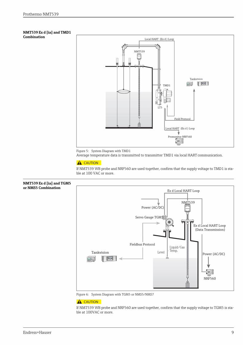
Figure 5: System Diagram with TMD1Average temperature data is transmitted to transmitter TMD1 via local HART communication.
If NMT539 WB probe and NRF560 are used together, confirm that the supply voltage to TMD1 is sta-ble at 100 VAC or more.
NMT539 Ex d [ia] and TGM5 or NMS5 Combination
Figure 6: System Diagram with TGM5 or NMS5/NMS7
If NMT539 WB probe and NRF560 are used together, confirm that the supply voltage to TGM5 is sta-ble at 100VAC or more.
Local HART (Ex d ) Loop
NMT539
Field Protocol
Local HART (Ex d ) Loop
TMD1
LT5
Promonitor NRF560
Tankvisionvision
CAUTION
Power (AC/DC)
Servo Gauge TGM5
Ex d Local HART Loop
NMT539
Ex d Local HART Loop (Data Transmission)
Power (AC/DC)
NRF560
LevelLiquid/Gas Temp.
Fieldbus Protocol
Tankvisionvision
CAUTION
Prothermo NMT539
10 Endress+Hauser
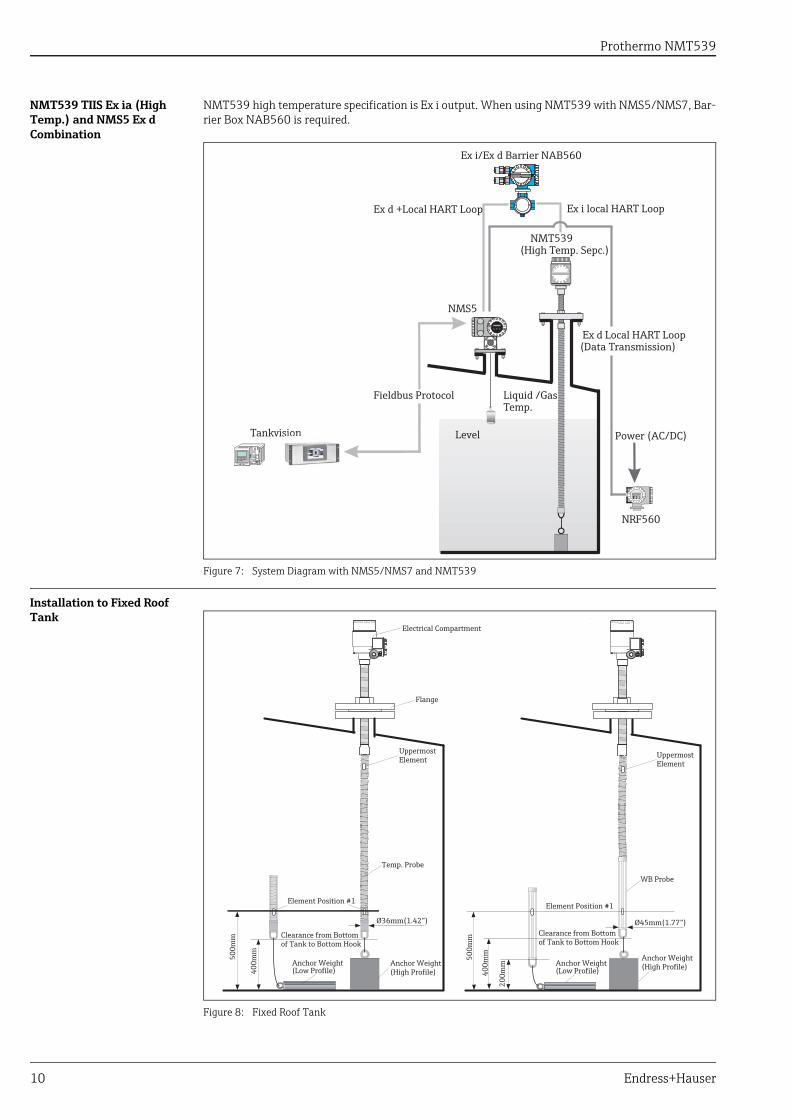
NMT539 TIIS Ex ia (High Temp.) and NMS5 Ex d Combination
NMT539 high temperature specification is Ex i output. When using NMT539 with NMS5/NMS7, Bar-rier Box NAB560 is required.
Figure 7: System Diagram with NMS5/NMS7 and NMT539
Installation to Fixed Roof Tank
Figure 8: Fixed Roof Tank
NMS5
NMT539(High Temp. Sepc.)
Ex d +Local HART Loop
Ex d Local HART Loop (Data Transmission)
Power (AC/DC)
NRF560
Level
Liquid /Gas Temp.
Ex i local HART Loop
Ex i/Ex d Barrier NAB560
Tankvisionsion
Fieldbus Protocol
Electrical Compartment
Flange
UppermostElement
Temp. Probe
Element Position #1
Ø36mm(1.42”)
Clearance from Bottomof Tank to Bottom Hook
500m
m
400m
m
Anchor Weight(Low Profile)
Anchor Weight(High Profile)
Element Position #1
Clearance from Bottomof Tank to Bottom Hook
400m
m500m
m
200m
m
Ø45mm(1.77”)
WB Probe
UppermostElement
Anchor Weight(Low Profile)
Anchor Weight(High Profile)
Prothermo NMT539
Endress+Hauser 11
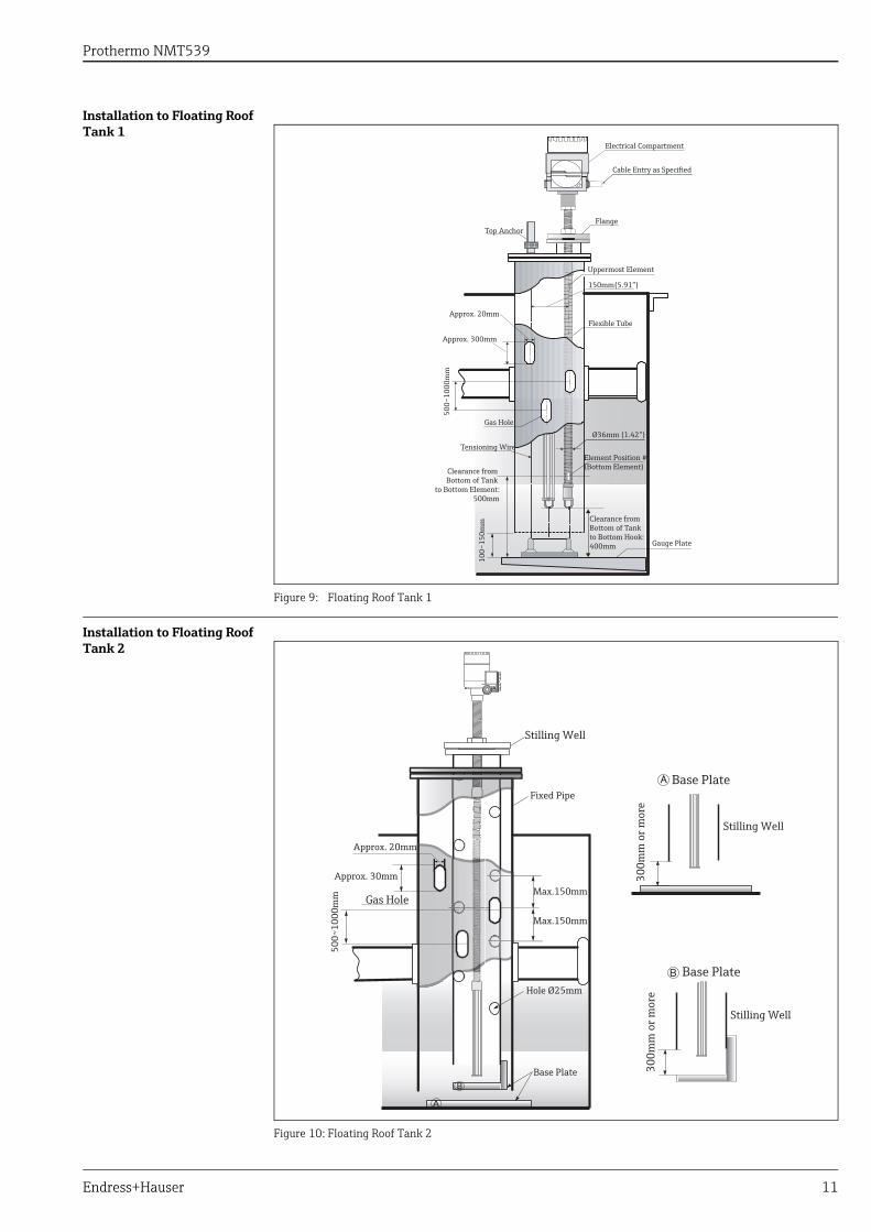
Installation to Floating Roof Tank 1
Figure 9: Floating Roof Tank 1
Installation to Floating Roof Tank 2
Figure 10: Floating Roof Tank 2
Electrical Compartment
Cable Entry as Specified
FlangeTop Anchor
Uppermost Element
150mm(5.91”)
Flexible Tube
Ø36mm (1.42”)
Element Position #(Bottom Element)
Gauge Plate
Clearance fromBottom of Tank to Bottom Hook:400mm
100~
150m
mClearance from Bottom of Tank
to Bottom Element:500mm
Tensioning Wire
Gas Hole
500~
1000
mm
Approx. 20mm
Approx. 300mm
Fixed Pipe
Stilling Well
Gas Hole
Approx. 20mm
Approx. 30mm
500~
1000
mm Max.150mm
Max.150mm
Hole Ø25mm
Base Plate
Stilling Well
Stilling Well
300m
m o
r mor
e30
0mm
or m
ore
Base Plate
Base Plate
Prothermo NMT539
12 Endress+Hauser
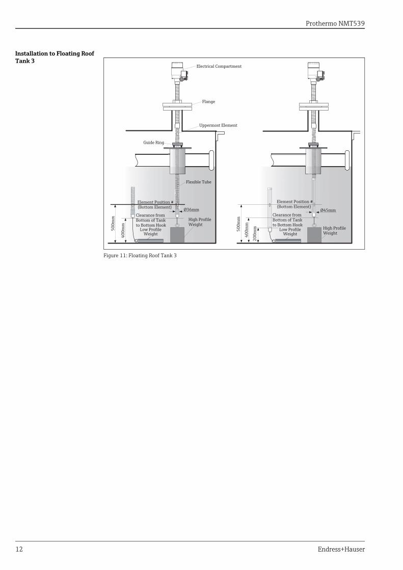
Installation to Floating Roof Tank 3
Figure 11: Floating Roof Tank 3
Electrical Compartment
Flange
Uppermost Element
Guide Ring
Flexible Tube
Element Position #(Bottom Element) Ø36mm
Low ProfileWeight
High ProfileWeight
500m
m
400m
m
Clearance from Bottom of Tank to Bottom Hook
500m
m
400m
m
200m
m
Clearance fromBottom of Tankto Bottom Hook
Element Position #(Bottom Element)
High ProfileWeight
Ø45mm
Low ProfileWeight
Prothermo NMT539
Endress+Hauser 13
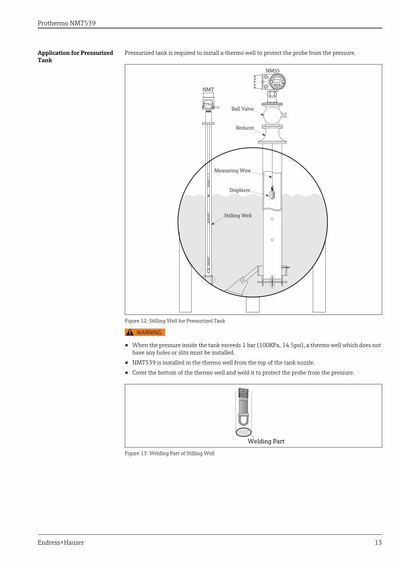
Application for Pressurized Tank
Pressurized tank is required to install a thermo well to protect the probe from the pressure.
Figure 12: Stilling Well for Pressurized Tank
• When the pressure inside the tank exceeds 1 bar (100KPa, 14.5psi), a thermo well which does not have any holes or slits must be installed.
• NMT539 is installed in the thermo well from the top of the tank nozzle.
• Cover the bottom of the thermo well and weld it to protect the probe from the pressure.
Figure 13: Welding Part of Stilling Well
NMS5
Ball Valve
Reducer
NMT
Measuring Wire
Displacer
Stilling Well
WARNING
Welding Part
Prothermo NMT539
14 Endress+Hauser
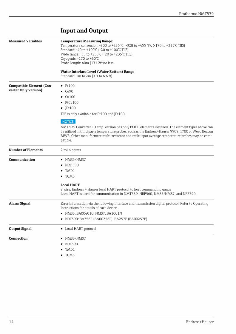
Input and Output
Measured Variables Temperature Measuring Range:Temperature conversion: -200 to +235 °C (-328 to +455 °F), (-170 to +235°C TIIS) Standard: -40 to +100°C (-20 to +100°C TIIS)Wide range: -55 to +235°C (-20 to +235°C TIIS)Cryogenic: -170 to +60°CProbe length: 40m (131.2ft)or less
Water Interface Level (Water Bottom) Range Standard: 1m to 2m (3.3 to 6.6 ft)
Compatible Element (Con-verter Only Version)
• Pt100• Cu90• Cu100• PtCu100• JPt100
TIIS is only available for Pt100 and JPt100.
NMT 539 Converter + Temp. version has only Pt100 elements installed. The element types above can be utilized in third party temperature probes, such as the Endress+Hauser 9909, 1700 or Weed Beacon MWR. Other manufacturer multi-resistant and multi-spot average temperature probes may be com-patible.
Number of Elements 2 to16 points
Communication • NMS5/NMS7 • NRF 590• TMD1• TGM5
Local HART2 wire, Endress + Hauser local HART protocol to host commanding gaugeLocal HART is used for communication in NMT539, NRF560, NMS5/NMS7, and NRF590.
Alarm Signal Error information via the following interface and transmission digital protocol. Refer to Operating Instructions for details of each device. • NMS5: BA00401G, NMS7: BA1001N• NRF590: BA256F (BA00256F), BA257F (BA00257F)
Output Signal • Local HART protocol
Connection • NMS5/NMS7• NRF590• TMD1• TGM5
NOTICE
Prothermo NMT539
Endress+Hauser 15
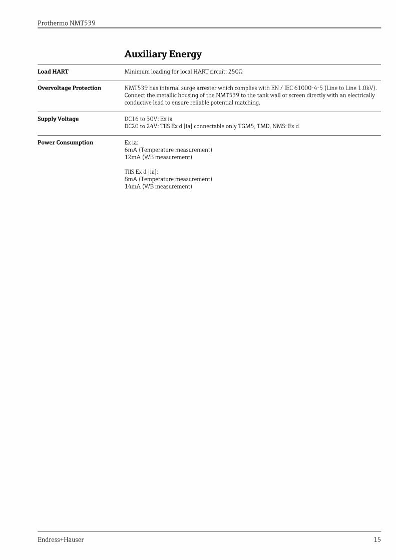
Auxiliary Energy
Load HART Minimum loading for local HART circuit: 250Ω
Overvoltage Protection NMT539 has internal surge arrester which complies with EN / IEC 61000-4-5 (Line to Line 1.0kV).Connect the metallic housing of the NMT539 to the tank wall or screen directly with an electrically conductive lead to ensure reliable potential matching.
Supply Voltage DC16 to 30V: Ex iaDC20 to 24V: TIIS Ex d [ia] connectable only TGM5, TMD, NMS: Ex d
Power Consumption Ex ia:6mA (Temperature measurement)12mA (WB measurement)
TIIS Ex d [ia]:8mA (Temperature measurement)14mA (WB measurement)
Prothermo NMT539
16 Endress+Hauser
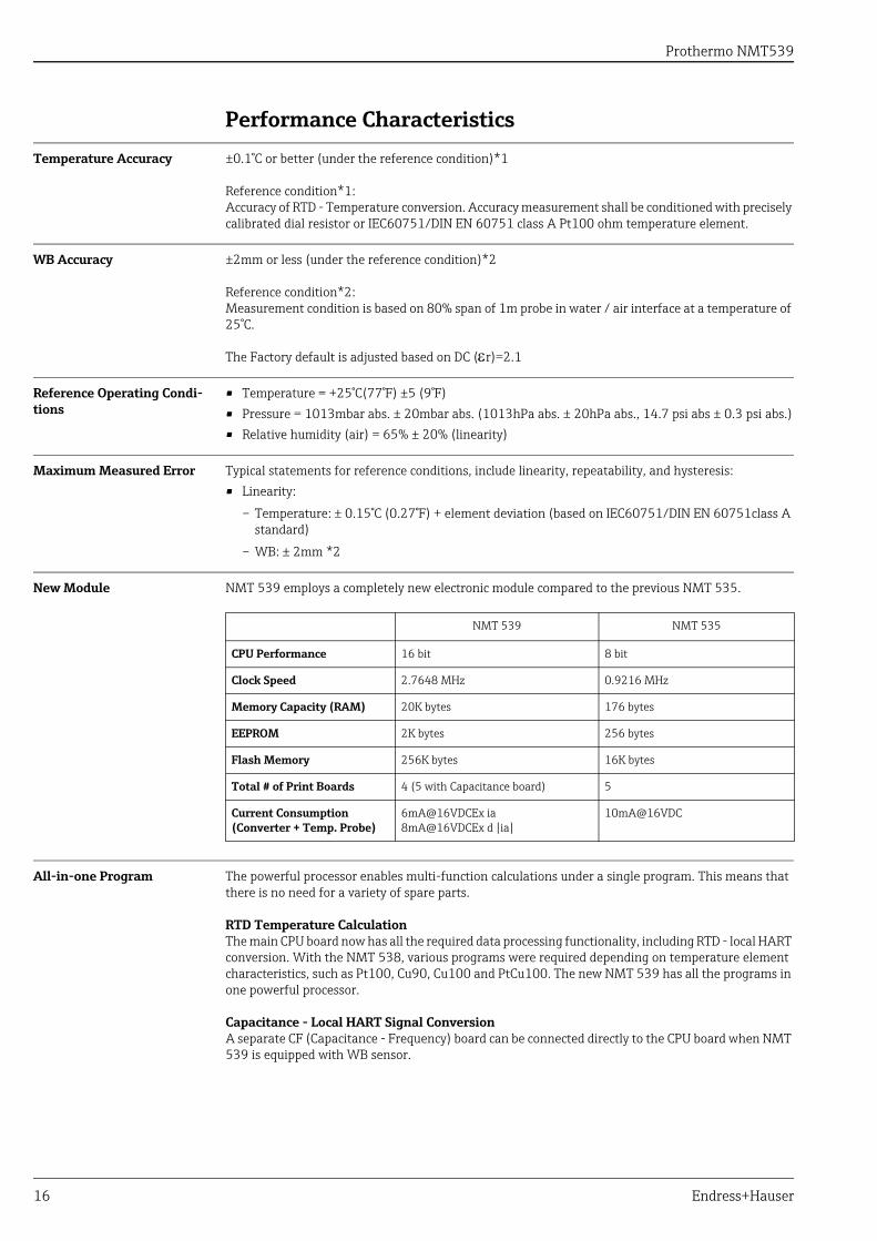
Performance Characteristics
Temperature Accuracy ±0.1°C or better (under the reference condition)*1
Reference condition*1:Accuracy of RTD - Temperature conversion. Accuracy measurement shall be conditioned with precisely calibrated dial resistor or IEC60751/DIN EN 60751 class A Pt100 ohm temperature element.
WB Accuracy ±2mm or less (under the reference condition)*2
Reference condition*2:Measurement condition is based on 80% span of 1m probe in water / air interface at a temperature of 25°C.
The Factory default is adjusted based on DC (r)=2.1
Reference Operating Condi-tions
• Temperature = +25°C(77°F) ±5 (9°F)• Pressure = 1013mbar abs. ± 20mbar abs. (1013hPa abs. ± 20hPa abs., 14.7 psi abs ± 0.3 psi abs.)• Relative humidity (air) = 65% ± 20% (linearity)
Maximum Measured Error Typical statements for reference conditions, include linearity, repeatability, and hysteresis:• Linearity:
– Temperature: ± 0.15°C (0.27°F) + element deviation (based on IEC60751/DIN EN 60751class A standard)
– WB: ± 2mm *2
New Module NMT 539 employs a completely new electronic module compared to the previous NMT 535.
All-in-one Program The powerful processor enables multi-function calculations under a single program. This means that there is no need for a variety of spare parts.
RTD Temperature CalculationThe main CPU board now has all the required data processing functionality, including RTD - local HART conversion. With the NMT 538, various programs were required depending on temperature element characteristics, such as Pt100, Cu90, Cu100 and PtCu100. The new NMT 539 has all the programs in one powerful processor.
Capacitance - Local HART Signal ConversionA separate CF (Capacitance - Frequency) board can be connected directly to the CPU board when NMT 539 is equipped with WB sensor.
NMT 539 NMT 535
CPU Performance 16 bit 8 bit
Clock Speed 2.7648 MHz 0.9216 MHz
Memory Capacity (RAM) 20K bytes 176 bytes
EEPROM 2K bytes 256 bytes
Flash Memory 256K bytes 16K bytes
Total # of Print Boards 4 (5 with Capacitance board) 5
Current Consumption (Converter + Temp. Probe)
6mA@16VDCEx ia8mA@16VDCEx d [ia]
10mA@16VDC
Prothermo NMT539
Endress+Hauser 17
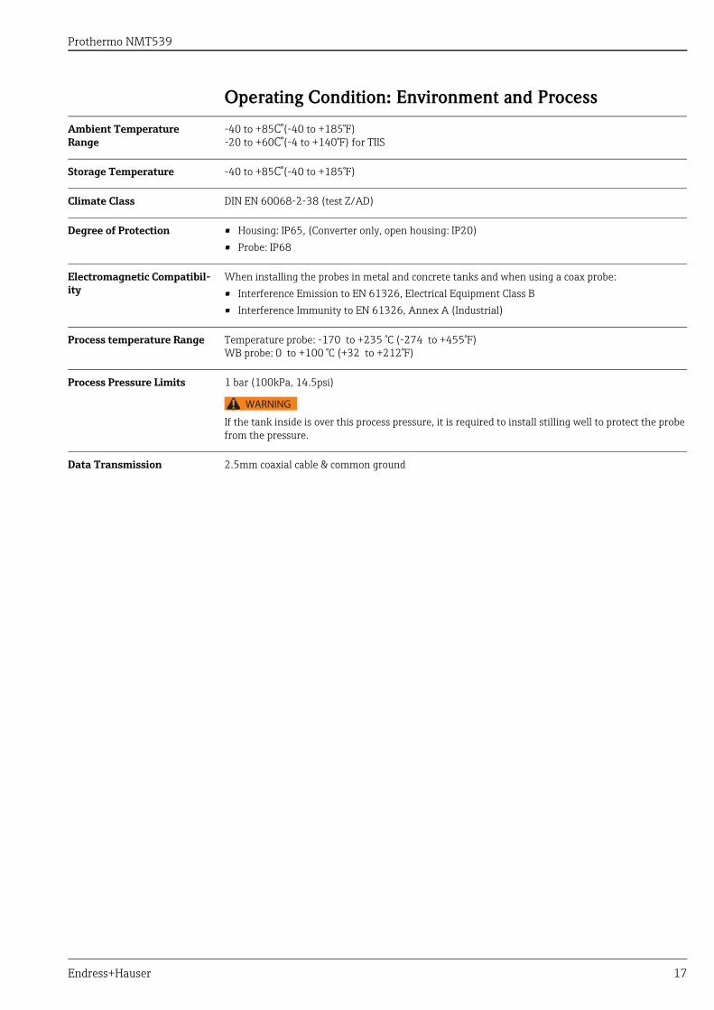
Operating Condition: Environment and Process
Ambient Temperature Range
-40 to +85C°(-40 to +185°F)-20 to +60C°(-4 to +140°F) for TIIS
Storage Temperature -40 to +85C°(-40 to +185°F)
Climate Class DIN EN 60068-2-38 (test Z/AD)
Degree of Protection • Housing: IP65, (Converter only, open housing: IP20)• Probe: IP68
Electromagnetic Compatibil-ity
When installing the probes in metal and concrete tanks and when using a coax probe:• Interference Emission to EN 61326, Electrical Equipment Class B• Interference Immunity to EN 61326, Annex A (Industrial)
Process temperature Range Temperature probe: -170 to +235 °C (-274 to +455°F)WB probe: 0 to +100 °C (+32 to +212°F)
Process Pressure Limits 1 bar (100kPa, 14.5psi)
If the tank inside is over this process pressure, it is required to install stilling well to protect the probe from the pressure.
Data Transmission 2.5mm coaxial cable & common ground
WARNING

Prothermo NMT539
18 Endress+Hauser
Operating Condition: Installation
Cable Grands Wiring of the NMT 539 must meet explosion proof or intrinsically safe requirements.The following cable entries are available:• Thread G 1/2"• Thread NPT 1/2"• Thread M20
Only G1/2 is selectable for TIIS Ex d [ia] and for TIIS Ex d [ia], 2 cable glands SXC-16B are attached.
Ensure to use the cable glands attached to NMT539.Cable gland is not provided for other NMT 539 specifications excluding TIIS Ex d [ia].Size and condition of the communication cable must meet the requirements of intrinsically safe local HART communication.
Process Connection Converter Only VersionNMT 539's local HART converter can fit onto third party average temperature probes with the follow-ing mechanical connection size and type:• G 3/4" (equivalent to NPS 3/4") universal coupling: Housing type 1• M20 threaded: housing type 2, specific design to fit to Varec 1700 terminal housing
• Use sealing tape to secure the connection between converter and temperature probe.• Refer to the NMT 539 instruction manual for the detailed installation procedure.
Converter + Temp. , Converter + Temp. + WB VersionAll versions have the same installation method to fit with the tank nozzle.The following flange sizes are available:• 10K 50A RF, 316, flange JIS B2220• NPS 2" Cl.150 RF, 316 flange ASME B16.5• DN50 PN10 B1, 316, flange EN1092-1 (DIN2527 B)• 50A 150lbs RF, 316, flange JPI 7S-15
Height Adjustment for NMT539
When installing NMT539, height adjustment can be performed within approximately ±180 mm (7") from the original height.
The height adjuster is not included in "Converter Only" version.
Tighten the lock nut with sealing tape to secure NMT 539 flange at the end of installation. A loose lock nut may lead to improper tank sealing or unexpected leakage into the tank.
WB Blocking Distance The Water Bottom sensor can be set as low as zero clearance from the tank floor by using height adjuster. Due to mechanical design of WB sensor, bottom plate has approximately 10mm thickness. This will become a blocking distance (ineffective measuring range).
Calculate vertical movement of NMT 539 installation height prior to setting the WB sensor bottom clearance. Typical tank shell deformation causes vertical movement at a minimum 20 ~ 30mm (1"). Excessive weight load of entire NMT 539 on WB sensor by contacting tank floor may cause critical damage that disables accurate & stable WB level measurement.
WARNING
CAUTION
NOTICE
WARNING
WARNING
Prothermo NMT539
Endress+Hauser 19
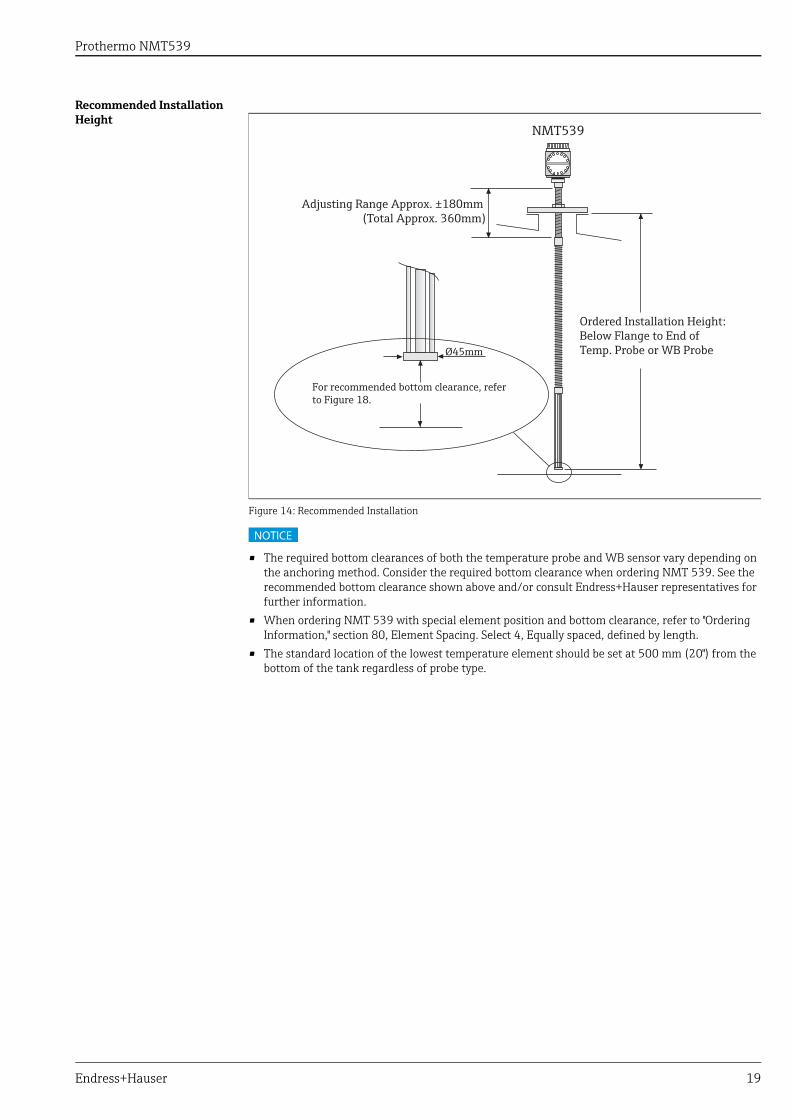
Recommended Installation Height
Figure 14: Recommended Installation
• The required bottom clearances of both the temperature probe and WB sensor vary depending on the anchoring method. Consider the required bottom clearance when ordering NMT 539. See the recommended bottom clearance shown above and/or consult Endress+Hauser representatives for further information.
• When ordering NMT 539 with special element position and bottom clearance, refer to "Ordering Information," section 80, Element Spacing. Select 4, Equally spaced, defined by length.
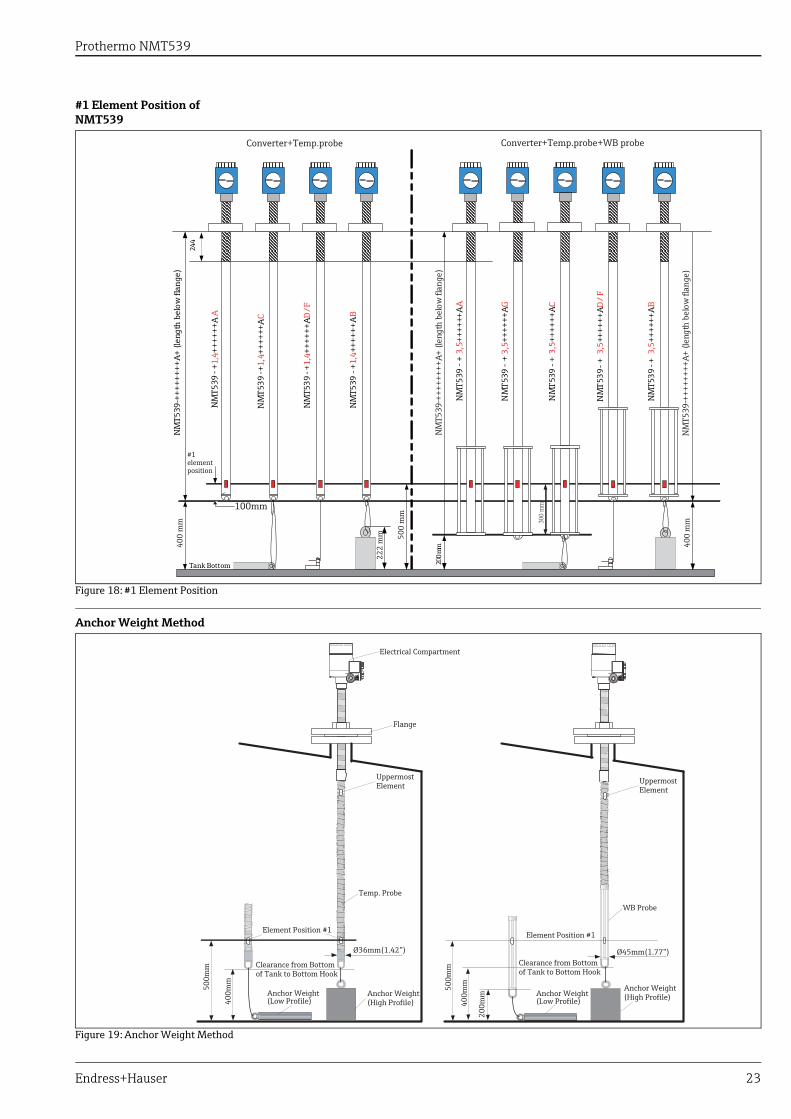
• The standard location of the lowest temperature element should be set at 500 mm (20") from the bottom of the tank regardless of probe type.
NMT539
Ordered Installation Height:Below Flange to End ofTemp. Probe or WB Probe
Adjusting Range Approx. ±180mm (Total Approx. 360mm)
For recommended bottom clearance, refer to Figure 18.
Ø45mm
NOTICE
Prothermo NMT539
20 Endress+Hauser
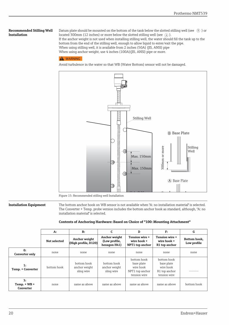
Recommended Stilling Well Installation
Datum plate should be mounted on the bottom of the tank below the slotted stilling well (see ) or located 300mm (12 inches) or more below the slotted stilling well (see ).If the anchor weight is not used when installing stilling well, the water should fill the tank up to the bottom from the end of the stilling well, enough to allow liquid to enter/exit the pipe.When using stilling well, it is available from 2 inches (50A) (JIS, ANSI) pipeWhen using anchor weight, use 4 inches (100A)(JIS, ANSI) pipe or more.
Avoid turbulence in the water so that WB (Water Bottom) sensor will not be damaged.
Figure 15: Recommended stilling well Installation
Installation Equipment The bottom anchor hook on WB sensor is not available when "A: no installation material" is selected. The Converter + Temp. probe version includes the bottom anchor hook as standard, although, "A: no installation material" is selected.
Contents of Anchoring Hardware: Based on Choice of "100: Mounting Attachment"
B
A
WARNING
Stilling Well
Base Plate
Stilling Well
e
Base Plate
Hole Ø 25mm
Max. 150mm
Max. 150mm
300m
m o
r mor
e
A: B: C D F: G
Not selectedAnchor weight
(High profile, D120)
Anchor weight (Low profile,
hexagon H41)
Tension wire + wire hook +
NPT1 top anchor
Tension wire + wire hook +
R1 top anchor
Bottom hook, Low profile
0: Converter only none none none none none none
1: Temp. + Converter bottom hook
bottom hookanchor weight
sling wire
bottom hookanchor weight
sling wire
bottom hookbase plate wire hook
NPT1 top anchortension wire
bottom hookbase plate wire hook
R1 top anchortension wire
--------
3: Temp. + WB +
Converternone same as above same as above same as above same as above bottom hook
Prothermo NMT539
Endress+Hauser 21
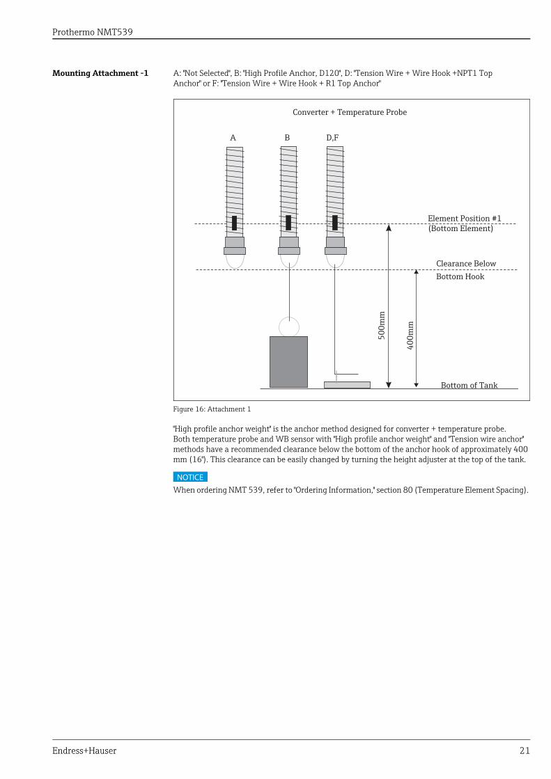
Mounting Attachment -1 A: "Not Selected", B: "High Profile Anchor, D120", D: "Tension Wire + Wire Hook +NPT1 Top Anchor" or F: "Tension Wire + Wire Hook + R1 Top Anchor"
Figure 16: Attachment 1
"High profile anchor weight" is the anchor method designed for converter + temperature probe.Both temperature probe and WB sensor with "High profile anchor weight" and "Tension wire anchor" methods have a recommended clearance below the bottom of the anchor hook of approximately 400 mm (16"). This clearance can be easily changed by turning the height adjuster at the top of the tank.
When ordering NMT 539, refer to "Ordering Information," section 80 (Temperature Element Spacing).
Element Position #1(Bottom Element)
Bottom of Tank50
0mm
400m
m
Clearance BelowBottom Hook
Converter + Temperature Probe
A B D,F
NOTICE
Prothermo NMT539
22 Endress+Hauser
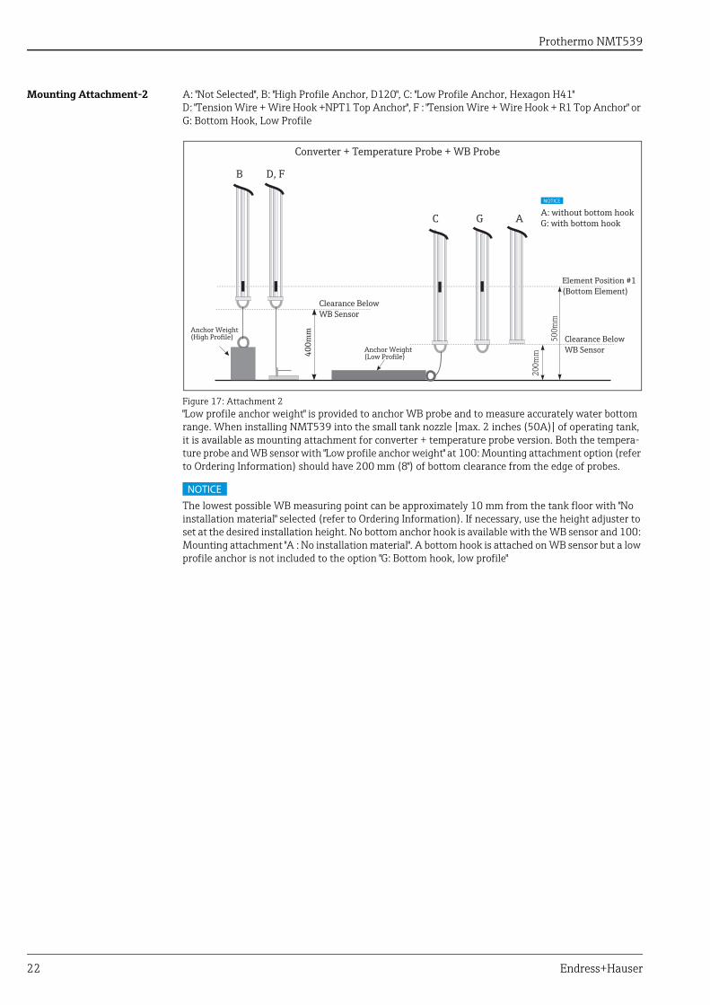
Mounting Attachment-2 A: "Not Selected", B: "High Profile Anchor, D120", C: "Low Profile Anchor, Hexagon H41"D: "Tension Wire + Wire Hook +NPT1 Top Anchor", F : "Tension Wire + Wire Hook + R1 Top Anchor" or G: Bottom Hook, Low Profile
Figure 17: Attachment 2"Low profile anchor weight" is provided to anchor WB probe and to measure accurately water bottom range. When installing NMT539 into the small tank nozzle [max. 2 inches (50A)] of operating tank, it is available as mounting attachment for converter + temperature probe version. Both the tempera-ture probe and WB sensor with "Low profile anchor weight" at 100: Mounting attachment option (refer to Ordering Information) should have 200 mm (8") of bottom clearance from the edge of probes.
The lowest possible WB measuring point can be approximately 10 mm from the tank floor with "No installation material" selected (refer to Ordering Information). If necessary, use the height adjuster to set at the desired installation height. No bottom anchor hook is available with the WB sensor and 100: Mounting attachment "A : No installation material". A bottom hook is attached on WB sensor but a low profile anchor is not included to the option "G: Bottom hook, low profile"
G AC
D, FB
Anchor Weight (High Profile)
Converter + Temperature Probe + WB Probe
400m
m
200m
m
500m
m
Clearance Below WB Sensor
Element Position #1(Bottom Element)
Anchor Weight (Low Profile)
Clearance Below WB Sensor
NOTICE
A: without bottom hookG: with bottom hook
NOTICE
Prothermo NMT539
Endress+Hauser 23
#1 Element Position of NMT539
Figure 18: #1 Element Position
Anchor Weight Method
Figure 19: Anchor Weight Method
NM
T539
-+1,
4+++
+++A
C
Tank Bottom
244
NM
T539
-+3,
5+++
+++A
A
NM
T539
-+1,
4+++
+++A
B
NM
T539
-+1,
4+++
+++A
D/F
NM
T539
-+3,
5+++
+++A
C
NM
T539
-+3,
5+++
+++A
D/F
NM
T539
-+3,
5+++
+++A
B
NM
T539
-+++
++++
+A+
(leng
th b
elow
flan
ge)
NM
T539
-+++
++++
+A+
(leng
th b
elow
flan
ge)
200 m
mN
MT5
39-+
++++
+++A
+ (le
ngth
bel
ow fl
ange
)
NM
T539
-+1,
4+++
+++A
A
300
mm
500
mm
400
mm
400
mm
Converter+Temp.probe Converter+Temp.probe+WB probe
222
mm
#1element position
NM
T539
-+
3,5+
++++
+AG
100mm
Electrical Compartment
Flange
UppermostElement
Temp. Probe
Element Position #1
Ø36mm(1.42”)
Clearance from Bottomof Tank to Bottom Hook
500m
m
400m
m
Anchor Weight(Low Profile)
Anchor Weight(High Profile)
Element Position #1
Clearance from Bottomof Tank to Bottom Hook
400m
m500m
m
200m
m
Ø45mm(1.77”)
WB Probe
UppermostElement
Anchor Weight(Low Profile)
Anchor Weight(High Profile)
Prothermo NMT539
24 Endress+Hauser
Operating Condition: Wiring
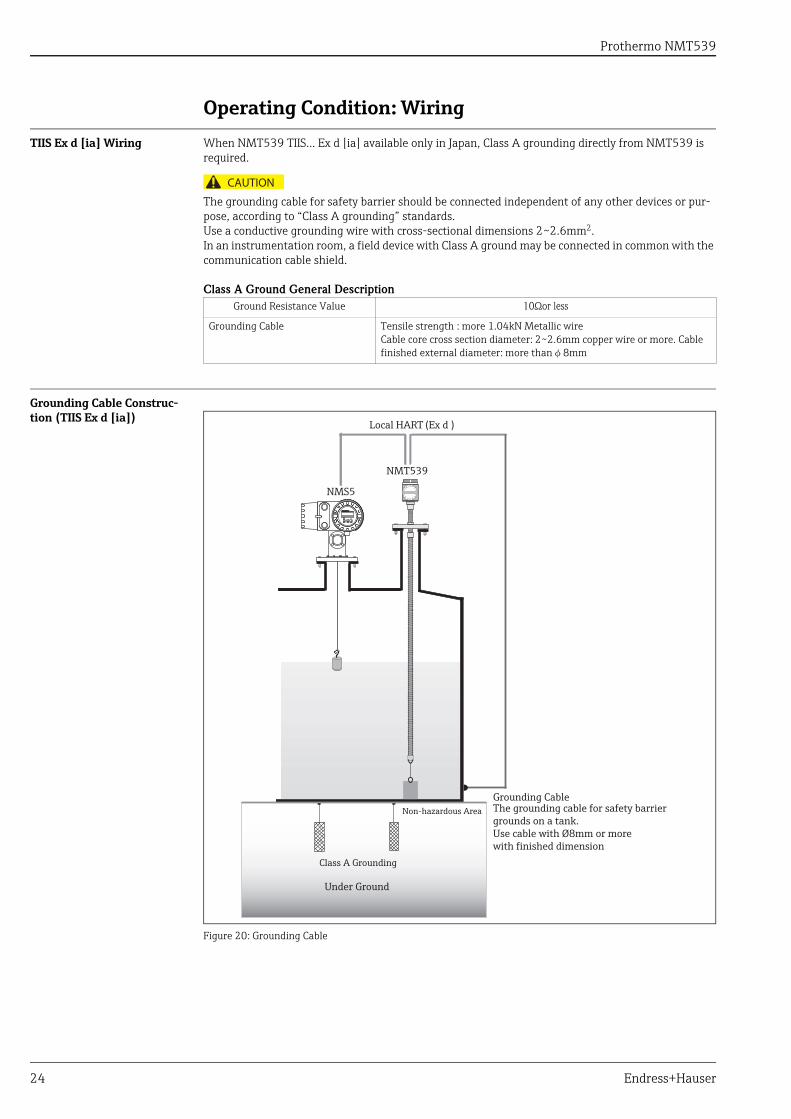
TIIS Ex d [ia] Wiring When NMT539 TIIS... Ex d [ia] available only in Japan, Class A grounding directly from NMT539 is required.
The grounding cable for safety barrier should be connected independent of any other devices or pur-pose, according to “Class A grounding” standards.Use a conductive grounding wire with cross-sectional dimensions 2~2.6mm2.In an instrumentation room, a field device with Class A ground may be connected in common with the communication cable shield.
Class A Ground General Description
Grounding Cable Construc-tion (TIIS Ex d [ia])
Figure 20: Grounding Cable
Ground Resistance Value 10Ωor less
Grounding Cable Tensile strength : more 1.04kN Metallic wireCable core cross section diameter: 2~2.6mm copper wire or more. Cable finished external diameter: more thanφ8mm
CAUTION
Local HART (Ex d )
NMS5
NMT539
Under Ground
Non-hazardous Area
Class A Grounding
Grounding CableThe grounding cable for safety barrier grounds on a tank.Use cable with Ø8mm or morewith finished dimension
Prothermo NMT539
Endress+Hauser 25
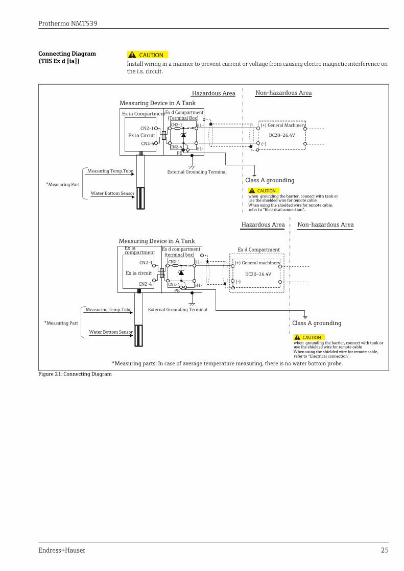
Connecting Diagram(TIIS Ex d [ia]) Install wiring in a manner to prevent current or voltage from causing electro magnetic interference on
the i.s. circuit.
Figure 21: Connecting Diagram
CAUTION
Hazardous Area Non-hazardous AreaMeasuring Device in A Tank
Ex ia Compartment Ex d Compartment (Terminal Box)
Ex ia Circuit
(+) General Machinery
External Grounding Terminal
Class A grounding
*Measuring Part
Measuring Device in A TankEx iacompartment Ex d compartment
(terminal box)
Ex ia circuit
Ex d Compartment
(+) General machinery
when grounding the barrier, connect with tank or use the shielded wire for remote cableWhen using the shielded wire for remote cable,refer to “Electrical connection”.
Class A grounding
*Measuring parts: In case of average temperature measuring, there is no water bottom probe.
DC20~26.4V
(-)
CN2-1
CN2-4
CN2-1
CN2-4PE
H1+
H1+
H1-
H1-
CN2-1
CN2-4
CN2-1
CN2-4PE
DC20~26.4V(-)
Measuring Temp.Tube
Water Bottom Sensor
*Measuring Part
Measuring Temp.Tube
Water Bottom Sensor
External Grounding Terminal
Hazardous Area Non-hazardous Area
CAUTION
when grounding the barrier, connect with tank or use the shielded wire for remote cableWhen using the shielded wire for remote cable,refer to “Electrical connection”.
CAUTION
Prothermo NMT539
26 Endress+Hauser
Operating Condition: Terminal Connection
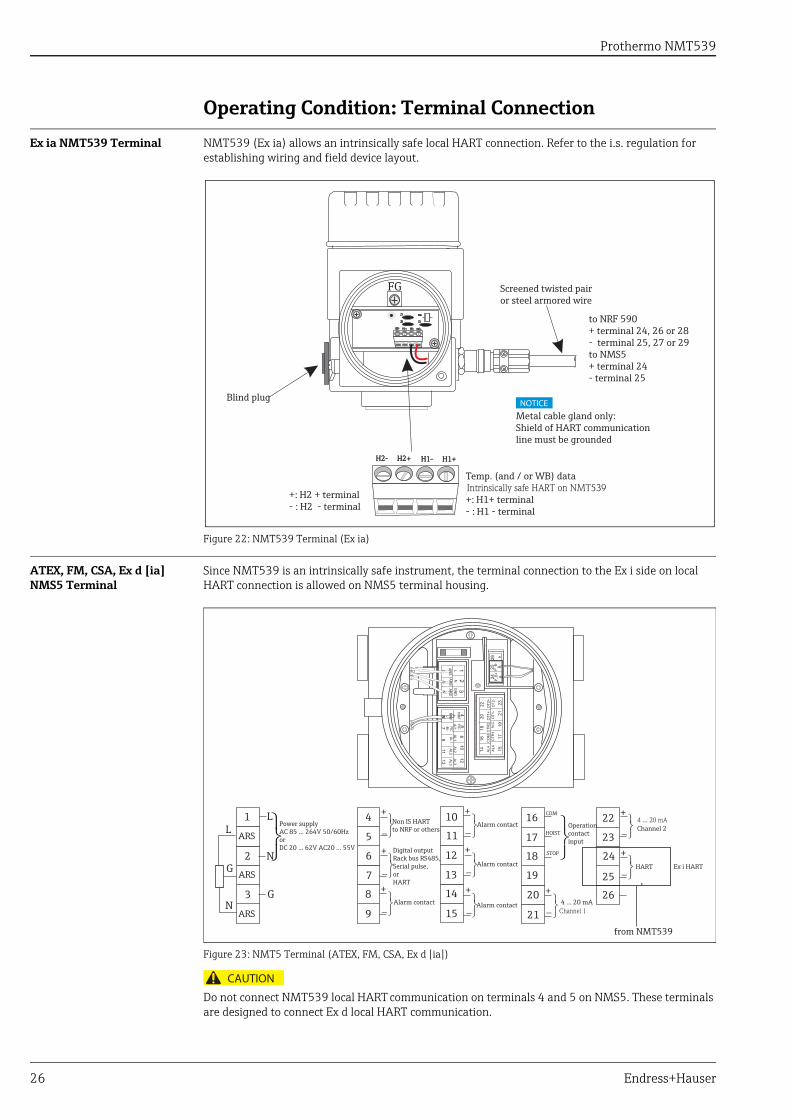
Ex ia NMT539 Terminal NMT539 (Ex ia) allows an intrinsically safe local HART connection. Refer to the i.s. regulation for establishing wiring and field device layout.
Figure 22: NMT539 Terminal (Ex ia)
ATEX, FM, CSA, Ex d [ia] NMS5 Terminal
Since NMT539 is an intrinsically safe instrument, the terminal connection to the Ex i side on local HART connection is allowed on NMS5 terminal housing.
Figure 23: NMT5 Terminal (ATEX, FM, CSA, Ex d [ia])
Do not connect NMT539 local HART communication on terminals 4 and 5 on NMS5. These terminals are designed to connect Ex d local HART communication.
Z1
H2- H2+ H1- H1+
Z2 Z3
AR1
H2-H2- H2+H2+ H1-H1- H1+H1+
Blind plug
Temp. (and / or WB) data
+: H1+ terminal- : H1 - terminal
Screened twisted pair or steel armored wire
to NRF 590+ terminal 24, 26 or 28- terminal 25, 27 or 29to NMS5+ terminal 24- terminal 25
Metal cable gland only:Shield of HART communication line must be grounded
Intrinsically safe HART on NMT539+: H2 + terminal- : H2 - terminal
FG
NOTICE
4 ... 20 mA
4 ... 20 mA
Channel 1
Channel 2
HART
+
+
_
_
22
23
24
25
26+
_
COM
HOIST
STOP
Operationcontactinput
20
21
16
19
18
17Alarm contact
Alarm contact
Alarm contact
+
_
+
_
+
_10
15
14
13
12
11
Alarm contact
+
_
Non IS HARTto NRF or others
+
_
9
8
7
6
5
4Power supplyAC 85 ... 264V 50/60HzorDC 20 ... 62V AC20 ... 55V
2
3
1
G
N
LL
G
N
ARS
ARS
ARS+
_
Digital outputRack bus RS485,Serial pulse,orHART
from NMT539
Ex i HART
CAUTION
Prothermo NMT539
Endress+Hauser 27
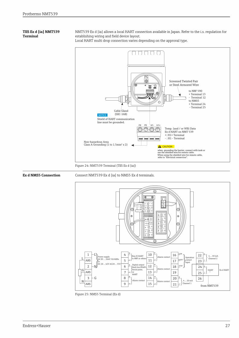
TIIS Ex d [ia] NMT539 Terminal
NMT539 Ex d [ia] allows a local HART connection available in Japan. Refer to the i.s. regulation for establishing wiring and field device layout.Local HART multi drop connection varies depending on the approval type.
Figure 24: NMT539 Terminal (TIIS Ex d [ia])
Ex d NMS5 Connection Connect NMT539 Ex d [ia] to NMS5 Ex d terminals.
Figure 25: NMS5 Terminal (Ex d)
Cable Gland (SXC-16B)
Screened Twisted Pair or Steel Armored Wire
to NRF 590+ Terminal 13- Terminal 12to NMS5+ Terminal 24 - Terminal 25
Shield of HART communication line must be grounded.
Temp. (and / or WB) DataEx d HART on NMT 539+: H1+ Terminal- : H1 - Terminal
when grounding the barrier, connect with tank or use the shielded wire for remote cable.When using the shielded wire for remote cable,refer to “Electrical connection”.
Non-hazardous Area Class A Grounding (1 to 1.5mm2 x 2)
NOTICE
FG
CAUTION
4 ... 20 mA
4 ... 20 mA
Channel 1
Channel 2
HART
+
+
_
_
22
23
24
25
26+
_
COM
HOIST
STOP
Operationcontactinput
20
21
16
19
18
17Alarm contact
Alarm contact
Alarm contact
+
_
+
_
+
_10
15
14
13
12
11
Alarm contact
+
_
Non IS HARTto NRF or others
+
_
9
8
7
6
5
4Power supplyAC 85 ... 264V 50/60HzorDC 20 ... 62V AC20 ... 55V
2
3
1
G
N
LL
G
N
ARS
ARS
ARS+
_
Digital outputRack bus RS485,Serial pulse,orHART
from NMT539
Ex d HART
NMT+
NMT-
Prothermo NMT539
28 Endress+Hauser
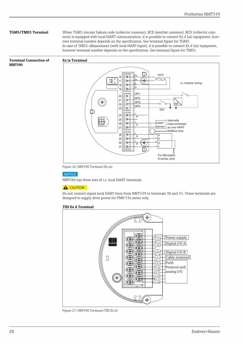
TGM5/TMD1 Terminal When TGM5 (except Sakura code (collector common), BCD (emitter common), BCD (collector com-mon) is equipped with local HART communication, it is possible to connect Ex d [ia] equipment, how-ever terminal number depends on the specification. See terminal figure for TGM5.In case of TMD1-xBxxxxxxxxx (with local HART input), it is possible to connect Ex d [ia] equipment, however terminal number depends on the specification. See terminal figure for TMD1.
Terminal Connection of NRF590
Ex ia Terminal
Figure 26: NRF590 Terminal (Ex ia)
NRF590 has three sets of i.s. local HART terminals.
Do not connect signal local HART lines from NMT539 to terminals 30 and 31. These terminals are designed to supply drive power for FMR 53x series only.
TIIS Ex d Terminal
Figure 27: NRF590 Terminal (TIIS Ex d)
24V
mA
NOTICE
CAUTION
Power supplyDigital I/O A
FieldProtocol andanalog I/O
Digital I/O BCable screened
Prothermo NMT539
Endress+Hauser 29
Mechanical Construction
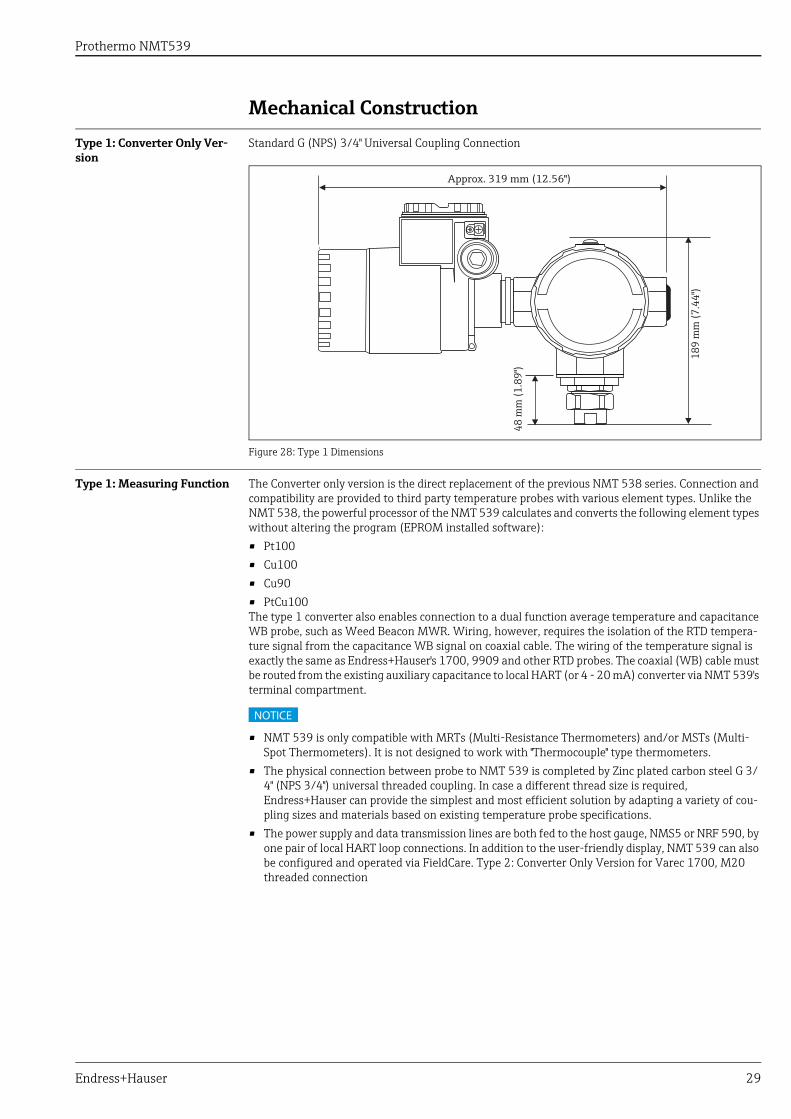
Type 1: Converter Only Ver-sion
Standard G (NPS) 3/4" Universal Coupling Connection
Figure 28: Type 1 Dimensions
Type 1: Measuring Function The Converter only version is the direct replacement of the previous NMT 538 series. Connection and compatibility are provided to third party temperature probes with various element types. Unlike the NMT 538, the powerful processor of the NMT 539 calculates and converts the following element types without altering the program (EPROM installed software): • Pt100• Cu100• Cu90• PtCu100The type 1 converter also enables connection to a dual function average temperature and capacitance WB probe, such as Weed Beacon MWR. Wiring, however, requires the isolation of the RTD tempera-ture signal from the capacitance WB signal on coaxial cable. The wiring of the temperature signal is exactly the same as Endress+Hauser's 1700, 9909 and other RTD probes. The coaxial (WB) cable must be routed from the existing auxiliary capacitance to local HART (or 4 - 20 mA) converter via NMT 539's terminal compartment.
• NMT 539 is only compatible with MRTs (Multi-Resistance Thermometers) and/or MSTs (Multi-Spot Thermometers). It is not designed to work with "Thermocouple" type thermometers.
• The physical connection between probe to NMT 539 is completed by Zinc plated carbon steel G 3/4" (NPS 3/4") universal threaded coupling. In case a different thread size is required, Endress+Hauser can provide the simplest and most efficient solution by adapting a variety of cou-pling sizes and materials based on existing temperature probe specifications.
• The power supply and data transmission lines are both fed to the host gauge, NMS5 or NRF 590, by one pair of local HART loop connections. In addition to the user-friendly display, NMT 539 can also be configured and operated via FieldCare. Type 2: Converter Only Version for Varec 1700, M20 threaded connection
Approx. 319 mm (12.56")
189
mm
(7.4
4")
48 m
m (1
.89"
)
NOTICE
Prothermo NMT539
30 Endress+Hauser
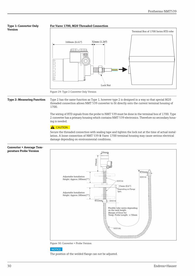
Type 1: Converter Only Version
For Varec 1700, M20 Threaded Connection
Figure 29: Type 2 Converter Only Version
Type 2: Measuring Function Type 2 has the same function as Type 1, however type 2 is designed in a way so that special M20 threaded connection allows NMT 539 converter to fit directly onto the current terminal housing of 1700.
The wiring of RTD signals from the probe to NMT 539 must be done in the terminal box of 1700. Type 2 converter has a primary housing which contains NMT 539 electronics. Therefore no secondary hous-ing is needed.
Secure the threaded connection with sealing tape and tighten the lock nut at the time of actual instal-lation. A loose connection of NMT 539 & Varec 1700 terminal housing may cause serious electrical damage depending on environmental conditions.
Converter + Average Tem-perature Probe Version
Figure 30: Converter + Probe Version
The position of the welded flange can not be adjusted.
168mm (6.61") 32mm (1.26")
Terminal Box of 1700 Series RTD robe
Lock Nut
CAUTION
Adjustable InstallationHeight: Approx.180mm(7”)
15mm (0.6”)
Flexible tube varies depending on the tank height.Margin of Error for Temp. Probe Length : ± 50mm
104mm
194m
m
Ø32mm
Ø36mm
*Depending on Flange Spec.
SUS316
SUS316
SUS316L
SUS316
Adjustable Installation Height: Approx.180mm(7”)
NOTICE
Prothermo NMT539
Endress+Hauser 31
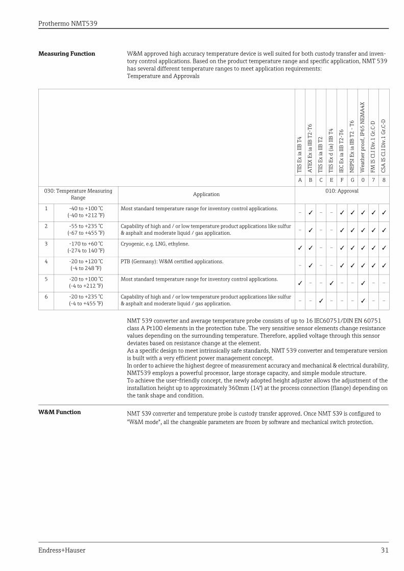
Measuring Function W&M approved high accuracy temperature device is well suited for both custody transfer and inven-tory control applications. Based on the product temperature range and specific application, NMT 539 has several different temperature ranges to meet application requirements:Temperature and Approvals
NMT 539 converter and average temperature probe consists of up to 16 IEC60751/DIN EN 60751 class A Pt100 elements in the protection tube. The very sensitive sensor elements change resistance values depending on the surrounding temperature. Therefore, applied voltage through this sensor deviates based on resistance change at the element.As a specific design to meet intrinsically safe standards, NMT 539 converter and temperature version is built with a very efficient power management concept.In order to achieve the highest degree of measurement accuracy and mechanical & electrical durability,NMT539 employs a powerful processor, large storage capacity, and simple module structure.To achieve the user-friendly concept, the newly adopted height adjuster allows the adjustment of theinstallation height up to approximately 360mm (14") at the process connection (flange) depending on the tank shape and condition.
W&M Function NMT 539 converter and temperature probe is custody transfer approved. Once NMT 539 is configured to
"W&M mode", all the changeable parameters are frozen by software and mechanical switch protection.
TIIS
Ex
ia II
B T4
ATE
X Ex
ia II
B T2
-T6
TIIS
Ex
ia II
B T2
TIIS
Ex
d (i
a) II
B T4
IEC
Ex ia
IIB
T2-T
6
NEP
SI E
x ia
IIB
T2 -
T6
Wea
ther
pro
of, I
P65
NEM
A4X
FM IS
Cl.I
Div
.1 G
r.C-D
CSA
IS C
l.I D
iv.1
Gr.C
-D
A B C E F G 0 7 8
030: Temperature Measuring Range
Application 010: Approval
1 -40 to +100 °C(-40 to +212 °F)
Most standard temperature range for inventory control applications.- - -
2 -55 to +235 °C(-67 to +455 °F)
Capability of high and / or low temperature product applications like sulfur & asphalt and moderate liquid / gas application. - - -
3 -170 to +60 °C(-274 to 140 °F)
Cryogenic, e.g. LNG, ethylene. - -
4 -20 to +120 °C(-4 to 248 °F)
PTB (Germany): W&M certified applications.- - -
5 -20 to +100 °C(-4 to +212 °F)
Most standard temperature range for inventory control applications. - - - - - -
6 -20 to +235 °C(-4 to +455 °F)
Capability of high and / or low temperature product applications like sulfur & asphalt and moderate liquid / gas application. - - - - - - -
Prothermo NMT539
32 Endress+Hauser
Converter + Average Temperature Probe + WB Probe Version
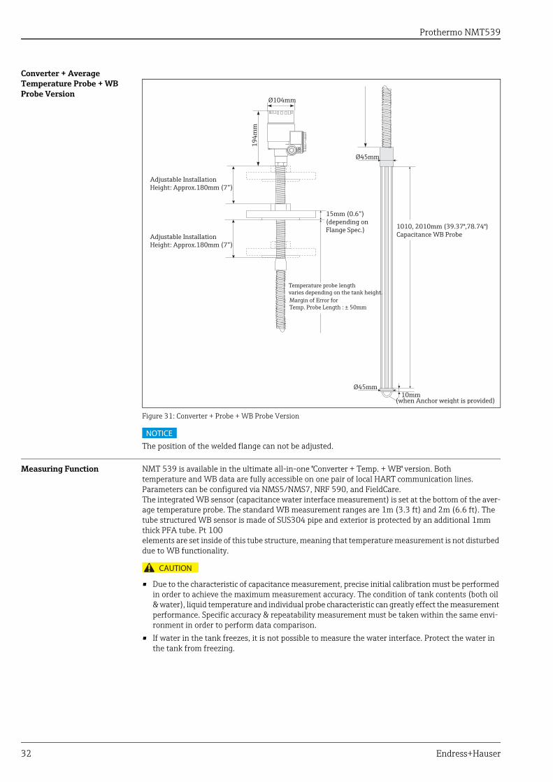
Figure 31: Converter + Probe + WB Probe Version
The position of the welded flange can not be adjusted.
Measuring Function NMT 539 is available in the ultimate all-in-one "Converter + Temp. + WB" version. Bothtemperature and WB data are fully accessible on one pair of local HART communication lines. Parameters can be configured via NMS5/NMS7, NRF 590, and FieldCare.The integrated WB sensor (capacitance water interface measurement) is set at the bottom of the aver-age temperature probe. The standard WB measurement ranges are 1m (3.3 ft) and 2m (6.6 ft). The tube structured WB sensor is made of SUS304 pipe and exterior is protected by an additional 1mm thick PFA tube. Pt 100elements are set inside of this tube structure, meaning that temperature measurement is not disturbed due to WB functionality.
• Due to the characteristic of capacitance measurement, precise initial calibration must be performed in order to achieve the maximum measurement accuracy. The condition of tank contents (both oil & water), liquid temperature and individual probe characteristic can greatly effect the measurement performance. Specific accuracy & repeatability measurement must be taken within the same envi-ronment in order to perform data comparison.
• If water in the tank freezes, it is not possible to measure the water interface. Protect the water in the tank from freezing.
Adjustable InstallationHeight: Approx.180mm (7”)
Adjustable InstallationHeight: Approx.180mm (7”)
1010, 2010mm (39.37",78.74")Capacitance WB Probe
(when Anchor weight is provided)
194m
m
Ø45mm
Ø45mm
10mm
Temperature probe length varies depending on the tank height.Margin of Error for Temp. Probe Length : ± 50mm
15mm (0.6”)(depending on Flange Spec.)
Ø104mm
NOTICE
CAUTION

Prothermo NMT539
Endress+Hauser 33
WB Probe Design
Figure 32: WB Prove Design
Welding Flange Type
Figure 33: Welding Flange
Because flange is completely welded, the waterproof is improved. However the position of the flange can not be adjusted after welding. The waterproof is only for TIIS.
Pt100 Element
Solid Structured Base Plate &Side Rods (SUS 316)
Up to 2 Pt100 elementcan be inserted.
Center Rod(SUS304 Tube)PFA Protection Tube
(1mm (0.04") Thickness)
92mmØ104mm
336.
5mm
Prothermo NMT539
34 Endress+Hauser
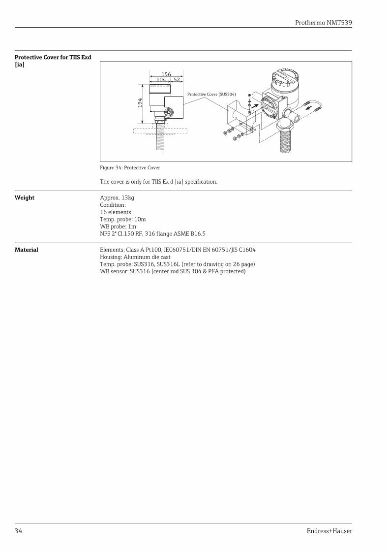
Protective Cover for TIIS Exd [ia]
Figure 34: Protective Cover
The cover is only for TIIS Ex d [ia] specification.
Weight Approx. 13kgCondition: 16 elementsTemp. probe: 10mWB probe: 1mNPS 2" Cl.150 RF, 316 flange ASME B16.5
Material Elements: Class A Pt100, IEC60751/DIN EN 60751/JIS C1604Housing: Aluminum die castTemp. probe: SUS316, SUS316L (refer to drawing on 26 page)WB sensor: SUS316 (center rod SUS 304 & PFA protected)
15652
Protective Cover (SUS304)
104
194

Prothermo NMT539
Endress+Hauser 35
Human Interface
Operation Using FieldCare NMT539 can also be operated via FieldCare Package. These programs support commissioning, secur-ing of data, signal analysis and documentation of the instruments.
FieldCare Packages support the following functions:• Online configuration of transmitters• Loading and saving of instrument data (Upload/Download)• Documentation of measuring points
Prothermo NMT539
36 Endress+Hauser
Certificates and Approvals
CE Mark By attaching the CE mark, Endress+Hauser confirms that the instruments pass the required tests.
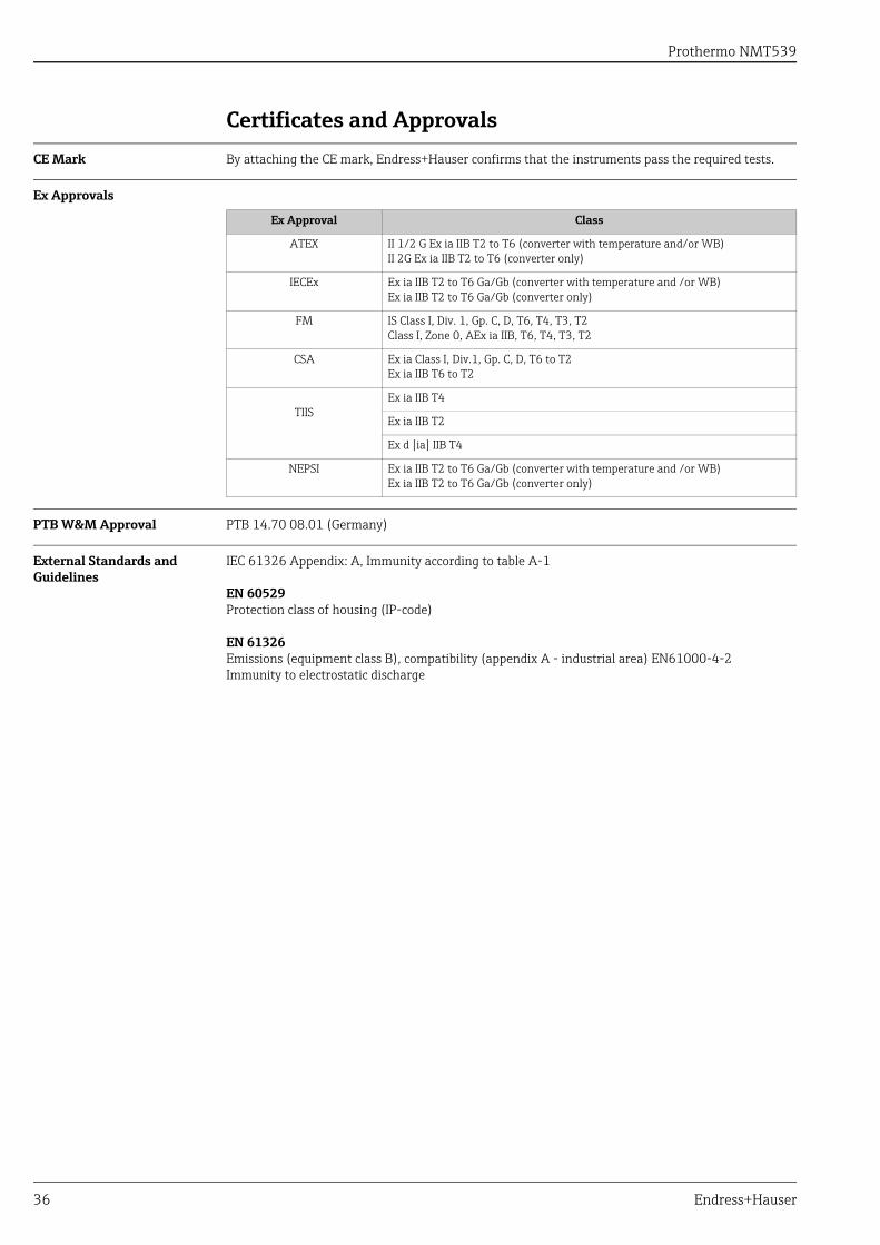
Ex Approvals
PTB W&M Approval PTB 14.70 08.01 (Germany)
External Standards and Guidelines
IEC 61326 Appendix: A, Immunity according to table A-1
EN 60529Protection class of housing (IP-code)
EN 61326Emissions (equipment class B), compatibility (appendix A - industrial area) EN61000-4-2 Immunity to electrostatic discharge
Ex Approval Class
ATEX II 1/2 G Ex ia IIB T2 to T6 (converter with temperature and/or WB)II 2G Ex ia IIB T2 to T6 (converter only)
IECEx Ex ia IIB T2 to T6 Ga/Gb (converter with temperature and /or WB)Ex ia IIB T2 to T6 Ga/Gb (converter only)
FM IS Class I, Div. 1, Gp. C, D, T6, T4, T3, T2Class I, Zone 0, AEx ia IIB, T6, T4, T3, T2
CSA Ex ia Class I, Div.1, Gp. C, D, T6 to T2Ex ia IIB T6 to T2
TIISEx ia IIB T4
Ex ia IIB T2
Ex d [ia] IIB T4
NEPSI Ex ia IIB T2 to T6 Ga/Gb (converter with temperature and /or WB)Ex ia IIB T2 to T6 Ga/Gb (converter only)
Prothermo NMT539
Endress+Hauser 37
Order Information
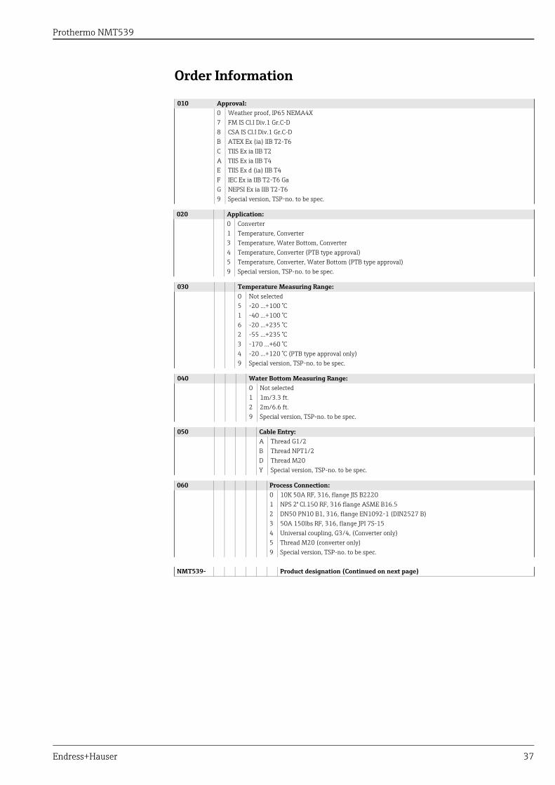
010 Approval:0 Weather proof, IP65 NEMA4X7 FM IS Cl.I Div.1 Gr.C-D8 CSA IS Cl.I Div.1 Gr.C-DB ATEX Ex (ia) IIB T2-T6C TIIS Ex ia IIB T2A TIIS Ex ia IIB T4E TIIS Ex d (ia) IIB T4F IEC Ex ia IIB T2-T6 GaG NEPSI Ex ia IIB T2-T69 Special version, TSP-no. to be spec.
020 Application:0 Converter1 Temperature, Converter3 Temperature, Water Bottom, Converter4 Temperature, Converter (PTB type approval)5 Temperature, Converter, Water Bottom (PTB type approval)9 Special version, TSP-no. to be spec.
030 Temperature Measuring Range:0 Not selected5 -20 ...+100 °C1 -40 ...+100 °C 6 -20 ...+235 °C2 -55 ...+235 °C3 -170 ...+60 °C4 -20 ...+120 °C (PTB type approval only)9 Special version, TSP-no. to be spec.
040 Water Bottom Measuring Range:0 Not selected1 1m/3.3 ft.2 2m/6.6 ft.9 Special version, TSP-no. to be spec.
050 Cable Entry:A Thread G1/2B Thread NPT1/2D Thread M20Y Special version, TSP-no. to be spec.
060 Process Connection:0 10K 50A RF, 316, flange JIS B22201 NPS 2" Cl.150 RF, 316 flange ASME B16.52 DN50 PN10 B1, 316, flange EN1092-1 (DIN2527 B)3 50A 150lbs RF, 316, flange JPI 7S-154 Universal coupling, G3/4, (Converter only)5 Thread M20 (converter only)9 Special version, TSP-no. to be spec.
NMT539- Product designation (Continued on next page)
Prothermo NMT539
38 Endress+Hauser
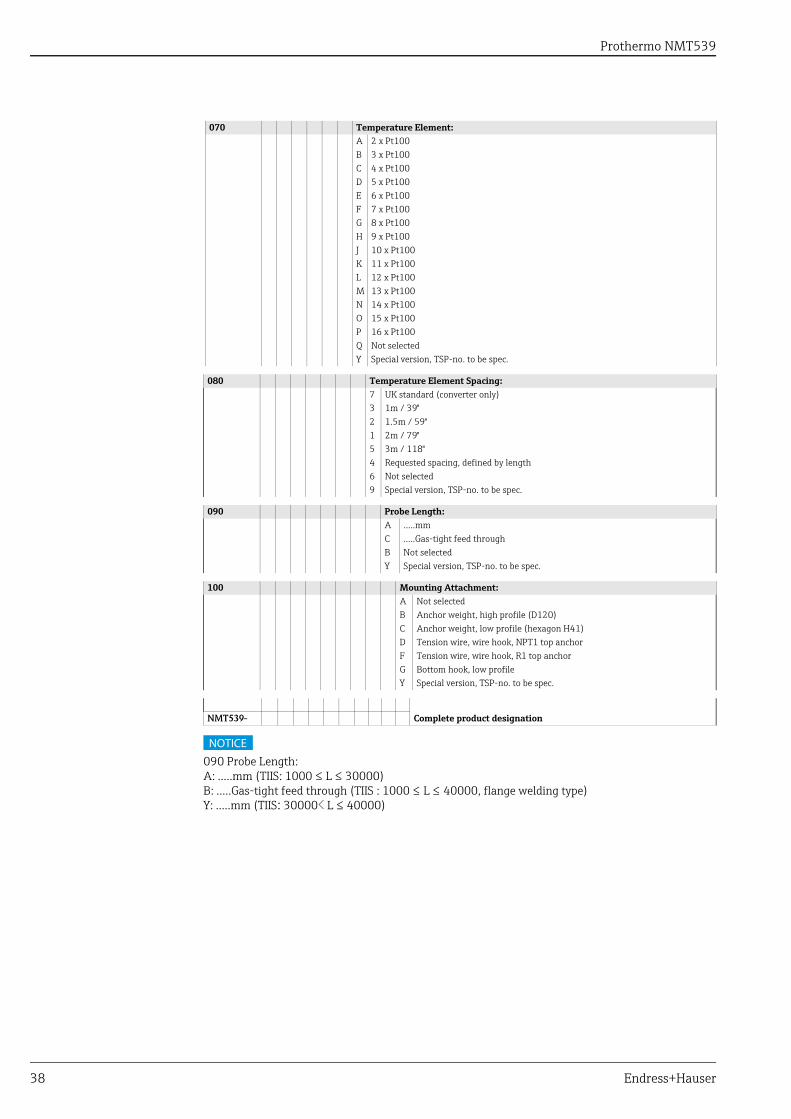
090 Probe Length:A: .....mm (TIIS: 1000 ≤ L ≤ 30000)B: .....Gas-tight feed through (TIIS : 1000 ≤ L ≤ 40000, flange welding type)Y: .....mm (TIIS: 30000< L ≤ 40000)
070 Temperature Element:A 2 x Pt100B 3 x Pt100C 4 x Pt100D 5 x Pt100E 6 x Pt100F 7 x Pt100G 8 x Pt100H 9 x Pt100J 10 x Pt100K 11 x Pt100L 12 x Pt100M 13 x Pt100N 14 x Pt100O 15 x Pt100P 16 x Pt100Q Not selectedY Special version, TSP-no. to be spec.
080 Temperature Element Spacing:7 UK standard (converter only)3 1m / 39"2 1.5m / 59"1 2m / 79"5 3m / 118"4 Requested spacing, defined by length6 Not selected9 Special version, TSP-no. to be spec.
090 Probe Length:A .....mm C .....Gas-tight feed throughB Not selectedY Special version, TSP-no. to be spec.
100 Mounting Attachment:A Not selectedB Anchor weight, high profile (D120)C Anchor weight, low profile (hexagon H41)D Tension wire, wire hook, NPT1 top anchorF Tension wire, wire hook, R1 top anchorG Bottom hook, low profileY Special version, TSP-no. to be spec.
NMT539- Complete product designation
NOTICE
Prothermo NMT539
Endress+Hauser 39
Accessories
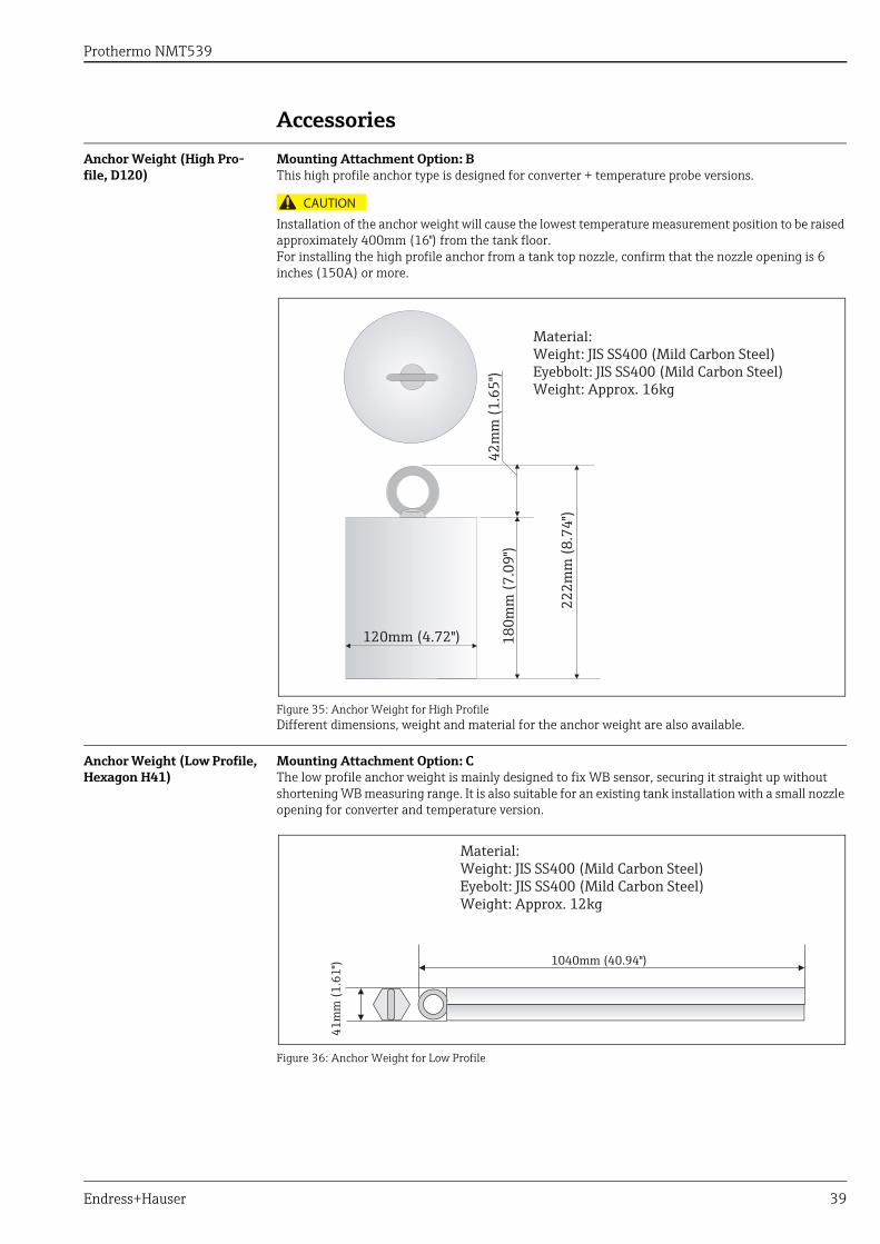
Anchor Weight (High Pro-file, D120)
Mounting Attachment Option: BThis high profile anchor type is designed for converter + temperature probe versions.
Installation of the anchor weight will cause the lowest temperature measurement position to be raised approximately 400mm (16") from the tank floor.For installing the high profile anchor from a tank top nozzle, confirm that the nozzle opening is 6 inches (150A) or more.
Figure 35: Anchor Weight for High ProfileDifferent dimensions, weight and material for the anchor weight are also available.
Anchor Weight (Low Profile, Hexagon H41)
Mounting Attachment Option: CThe low profile anchor weight is mainly designed to fix WB sensor, securing it straight up without shortening WB measuring range. It is also suitable for an existing tank installation with a small nozzle opening for converter and temperature version.
Figure 36: Anchor Weight for Low Profile
CAUTION
120mm (4.72") 180m
m (7
.09"
)
222m
m (8
.74"
)
42m
m (1
.65"
)
Material:Weight: JIS SS400 (Mild Carbon Steel)Eyebbolt: JIS SS400 (Mild Carbon Steel)Weight: Approx. 16kg
41m
m (1
.61"
) 1040mm (40.94")
Material:Weight: JIS SS400 (Mild Carbon Steel)Eyebolt: JIS SS400 (Mild Carbon Steel)Weight: Approx. 12kg
Prothermo NMT539
40 Endress+Hauser
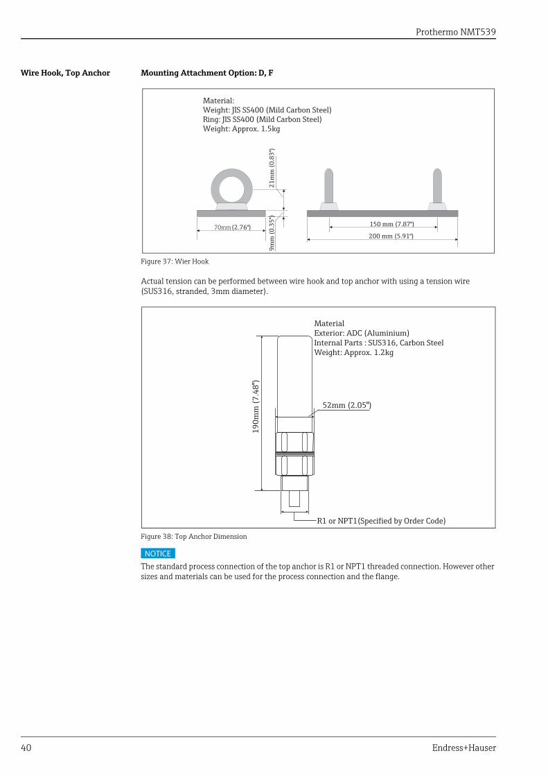
Wire Hook, Top Anchor Mounting Attachment Option: D, F
Figure 37: Wier Hook
Actual tension can be performed between wire hook and top anchor with using a tension wire (SUS316, stranded, 3mm diameter).
Figure 38: Top Anchor Dimension
The standard process connection of the top anchor is R1 or NPT1 threaded connection. However other sizes and materials can be used for the process connection and the flange.
9mm
(0.3
5")
21m
m (0
.83"
)
70mm (2.76")200 mm (5.91")
150 mm (7.87")
Material:Weight: JIS SS400 (Mild Carbon Steel)Ring: JIS SS400 (Mild Carbon Steel)Weight: Approx. 1.5kg
MaterialExterior: ADC (Aluminium)Internal Parts : SUS316, Carbon SteelWeight: Approx. 1.2kg
52mm (2.05")
190m
m (7
.48"
)
R1 or NPT1(Specified by Order Code)
NOTICE
Prothermo NMT539
Endress+Hauser 41
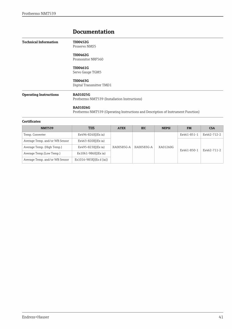
Documentation
Technical Information TI00452GProservo NMS5
TI00462GPromonitor NRF560
TI00461GServo Gauge TGM5
TI00463GDigital Transmitter TMD1
Operating Instructions BA01025GProthermo NMT539 (Installation Instructions)
BA01026GProthermo NMT539 (Operating Instructions and Description of Instrument Function)
Certificates
NMT539 TIIS ATEX IEC NEPSI FM CSA
Temp. Converter Ex496-826XJ(Ex ia)
XA00585G-A XA00583G-A XA01260G
Ex461-851-1 Ex462-712-2
Average Temp. and/or WB Sensor Ex463-820XJ(Ex ia)
Ex461-850-1 Ex462-711-2Average Temp. (High Temp.) Ex495-823XJ(Ex ia)
Average Temp.(Low Temp.) Ex1061-986XJ(Ex ia)
Average Temp. and/or WB Sensor Ex1016-983XJ(Ex d [ia])
Prothermo NMT539
42 Endress+Hauser
Appendix
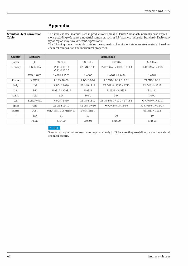
Stainless Steel Conversion Table
The stainless steel material used in products of Endress + Hauser Yamanashi normally have expres-sions according to Japanese industrial standards, such as JIS (Japanese Industrial Standard). Each coun-try or region may have different expressions.The following conversion table contains the expression of equivalent stainless steel material based on chemical composition and mechanical properties.
Standards may be not necessarily correspond exactly to JIS, because they are defined by mechanical and chemical criteria.
Country Standard Expressions
Japan JIS SUS304 SUS304L SUS316 SUS316L
Germany DIN 17006 X5 CrNi 18 10 X5 CrNi 18 12
X2 CrNi 18 11 X5 CrNiMo 17 12 2 / 1713 3 X2 CrNiMo 17 13 2
W.N. 17007 1.4301 1.4303 1.4306 1.4401 / 1.4436 1.4404
France AFNOR Z 6 CN 18-09 Z 2CN 18-10 Z 6 CND 17-11 / 17 12 Z2 CND 17-12
Italy UNI X5 CrNi 1810 X2 CrNi 1911 X5 CrNiMo 1712 / 1713 X2 CrNiMo 1712
U.K. BSI 304S15 / 304S16 304S11 316S31 / 316S33 316S11
U.S.A. AISI 304 304 L 316 316L
U.E. EURONORM X6 CrNi 1810 X3 CrNi 1810 X6 CrNiMo 17 12 2 / 17 13 3 X3 CrNiMo 17 12 2
Spain UNE X6 CrNi 19-10 X2 CrNi 19-10 X6 CrNiMo 17-12-03 X2 CrNiMo 17-12-03
Russia GOST 08KH18N10 06KH18N11 03KH18N11 _ 03KH17N14M2
- ISO 11 10 20 19
- ASME S30400 S30403 S31600 S31603
NOTICE

www.addresses.endress.com