Embed Size (px)
Citation preview
Original instructions
SI
TECHNICAL GUIDE Steel Light Crane System
English SUPDOC3D2548F-0.ORD 15.7.2016
- - - -
230322
TECHNICAL GUIDE
This document and the information contained herein, is the exclusive property of STAHL CraneSystems Gmbh and represents a non-public, confidential and proprietary trade secret that may not be reproduced, disclosed to third parties, altered or otherwise employed in any manner whatsoever without the express written consent of STAHL CraneSystems Gmbh. Copyright © (2013) STAHL CraneSystems Gmbh. All rights reserved.
2/111
Table of contents
1 UPDATE HISTORY ............................................................................................................................ 4
2 GENERAL INTRODUCTION .............................................................................................................. 5
2.1 About this manual ................................................................................................................................... 5
2.2 Symbols used in this manual ................................................................................................................... 5
2.3 Terminology ............................................................................................................................................ 5
2.4 About this product ................................................................................................................................... 6
2.4.1 Technical regulations .......................................................................................................................... 6
2.4.2 Safety regulations ............................................................................................................................... 7
2.4.3 Installation of light crane system .......................................................................................................... 7
2.4.4 Inspection, preventive maintenance..................................................................................................... 8
2.4.5 Other relevant documents ................................................................................................................. 10
3 PRODUCT RANGE .......................................................................................................................... 11
3.1 Environmental conditions ...................................................................................................................... 11
3.2 Steel light crane kit at a glance .............................................................................................................. 12
3.2.1 Compatibility matrix - Crane system and lifting device........................................................................ 13
3.2.2 Compatibility matrix - Track size and crane bridge size ...................................................................... 14
3.2.3 Compatibility matrix - Circuits and components* ................................................................................ 14
3.3 Suspended cranes (downward forces) .................................................................................................. 15
3.3.1 Straight monorail ............................................................................................................................... 15
3.3.2 Single girder articulated crane bridge ................................................................................................ 16
3.3.3 Single girder rigid crane bridge .......................................................................................................... 18
3.3.4 Single girder low headroom crane bridge ........................................................................................... 20
3.3.5 Double girder articulated crane bridge ............................................................................................... 22
3.3.6 Double girder rigid crane bridge ........................................................................................................ 24
3.3.7 Double girder low headroom crane bridge ......................................................................................... 26
3.4 Advanced suspended cranes ................................................................................................................ 28
3.4.1 Circuit monorails ............................................................................................................................... 28
3.4.2 Long outreach crane bridges ............................................................................................................. 28
3.4.3 Telescopic crane bridges................................................................................................................... 28
3.4.4 Extended cross travel crane bridges .................................................................................................. 28
3.4.5 Energy power supply by inner conductors inside UKA40 rails ............................................................ 28
3.4.6 Redundant safety .............................................................................................................................. 28
4 LIGHT CRANE SYSTEM CONFIGURATION ................................................................................... 29
4.1 Selection of crane type .......................................................................................................................... 29
4.2 Quick selection ..................................................................................................................................... 30
4.2.1 Single girder crane bridges ................................................................................................................ 31
4.2.2 Double girder crane bridges .............................................................................................................. 34
4.2.3 Monorail ............................................................................................................................................ 37
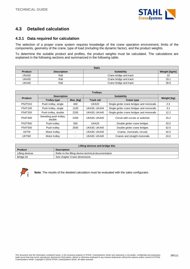
4.3 Detailed calculation ............................................................................................................................... 39
4.3.1 Data required for calculation .............................................................................................................. 39
4.3.2 Calculating load spectrum and determining rated capacity ................................................................. 40
4.3.3 Determining rail type ......................................................................................................................... 40
4.3.4 Suspension limits and forces back to supporting structure ................................................................. 46
4.3.5 Examples of calculations*.................................................................................................................. 46
4.4 Crane dimensions ................................................................................................................................. 54
4.4.1 Monorail ............................................................................................................................................ 55
4.4.2 Single girder articulated crane bridge ................................................................................................ 56
4.4.3 Single girder rigid crane bridge .......................................................................................................... 58
4.4.4 Single girder low headroom crane bridge ........................................................................................... 60
4.4.5 Double girder articulated crane bridge ............................................................................................... 62
4.4.6 Double girder rigid crane bridge ........................................................................................................ 64
4.4.7 Double girder low headroom crane bridge ......................................................................................... 66
TECHNICAL GUIDE
This document and the information contained herein, is the exclusive property of STAHL CraneSystems Gmbh and represents a non-public, confidential and proprietary trade secret that may not be reproduced, disclosed to third parties, altered or otherwise employed in any manner whatsoever without the express written consent of STAHL CraneSystems Gmbh. Copyright © (2013) STAHL CraneSystems Gmbh. All rights reserved.
3/111
5 CRANE COMPONENTS IN DETAIL ................................................................................................ 68
5.1 Interfaces with support steel works ........................................................................................................ 68
5.2 Suspension types with current suspension design ................................................................................. 70
5.2.1 Suspension for I-beam structure ........................................................................................................ 70
5.2.2 Suspension for straight ceiling ........................................................................................................... 73
5.2.3 Bracket type suspension ................................................................................................................... 75
5.2.4 Articulated suspensions..................................................................................................................... 77
5.3 Suspension types with suspension design upgrade 01/15* .................................................................... 79
5.3.1 Suspension for I-beam structure ........................................................................................................ 79
5.3.2 Suspension for straight ceiling ........................................................................................................... 81
5.3.3 Bracket type suspension ................................................................................................................... 83
5.3.4 Articulated suspensions..................................................................................................................... 85
5.3.5 Extension sets and side supports ...................................................................................................... 86
5.4 Rail profiles ........................................................................................................................................... 89
5.5 Connection sets .................................................................................................................................... 90
5.6 End plate sets and end stops ................................................................................................................ 91
5.7 Trolleys ................................................................................................................................................. 92
5.7.1 General characteristics ...................................................................................................................... 92
5.7.2 Single push trolley ............................................................................................................................. 92
5.7.3 Double push trolley ........................................................................................................................... 95
5.7.4 Motor trolleys UKTM and UKTM2 ...................................................................................................... 96
5.8 Energy supply ....................................................................................................................................... 98
5.8.1 Festoon under profile ........................................................................................................................ 98
5.8.2 Parallel enclosed conductors ........................................................................................................... 102
5.8.3 Inner conductors for UKA40 rails (UKA40-S) ................................................................................... 103
5.9 Electric kits for motor trolleys ............................................................................................................... 104
6 COMPONENTS FOR CIRCUITS AND MONORAILS .................................................................... 106
6.1 Maintenance hatch .............................................................................................................................. 106
6.2 Curved rails......................................................................................................................................... 107
6.3 Switches ............................................................................................................................................. 108
6.4 Turntable ............................................................................................................................................ 109
6.5 Area end stop ..................................................................................................................................... 110
6.6 Distance buffer .................................................................................................................................... 111
TECHNICAL GUIDE
This document and the information contained herein, is the exclusive property of STAHL CraneSystems Gmbh and represents a non-public, confidential and proprietary trade secret that may not be reproduced, disclosed to third parties, altered or otherwise employed in any manner whatsoever without the express written consent of STAHL CraneSystems Gmbh. Copyright © (2013) STAHL CraneSystems Gmbh. All rights reserved.
4/111
1 UPDATE HISTORY
Section Changes Date Handled by
All A new Technical guide document created for the Steel Light Crane System (SLCS) 07/2016 ISOTAPA
TECHNICAL GUIDE
This document and the information contained herein, is the exclusive property of STAHL CraneSystems Gmbh and represents a non-public, confidential and proprietary trade secret that may not be reproduced, disclosed to third parties, altered or otherwise employed in any manner whatsoever without the express written consent of STAHL CraneSystems Gmbh. Copyright © (2013) STAHL CraneSystems Gmbh. All rights reserved.
5/111
2 GENERAL INTRODUCTION
2.1 About this manual This technical guide describes the KS crane product content and basic selection rules. The technical guide supports other sales tools for proper product selection. This document includes the standard products available in the price lists and the sales configurator, as well as certain special applications that require separate offer engineering.
2.2 Symbols used in this manual The readers should familiarize themselves with the following symbols which are used in this manual.
Note: A note indicates items which require special attention from he reader. There is no obvious risk of injury associated with the notes.
2.3 Terminology
Light crane system Assembly of lifting equipment, crane bridges, trolleys, and tracks with their suspensions for lifting operations.
Crane bridge Steel rail carrying the lifting device and supported on trolleys running on tracks.
Track
Stationary steel rail on which a crane bridge or lifting device is running. A track consists of one or more track lines. In light crane systems, a track can be removed from the supporting building structures without influence on the strength of the supporting structures.
Suspension All necessary clamps, hanger rods, and other fittings by which a track is suspended from a building or other supporting structure.
Monorail Stationary steel rail on which the lifting device is running. The monorail together with a lifting device is a particular type of a light crane system.
Span Horizontal distance between the centers of the crane track rails.
Rated capacity Maximum net load that the crane is designed to lift for a given crane configuration and load location during normal operation.
Lifting device The equipment needed for lifting and lowering the load.
TECHNICAL GUIDE
This document and the information contained herein, is the exclusive property of STAHL CraneSystems Gmbh and represents a non-public, confidential and proprietary trade secret that may not be reproduced, disclosed to third parties, altered or otherwise employed in any manner whatsoever without the express written consent of STAHL CraneSystems Gmbh. Copyright © (2013) STAHL CraneSystems Gmbh. All rights reserved.
6/111
2.4 About this product The KS crane is a modular light crane system based on steel rails, which are proposed as kits, for manual or motorized operations. The crane kits can be used for suspending different lifting devices, although this document and the quick selection tables focus on the electric chain hoist. The lifting device is excluded from the crane kit and has to be calculated separately.
The crane system is designed to be suspended from a building or from a secondary steel structure, for example, a free standing system. The suspension is realized as a pendular system that allows horizontal displacements and downward forces. A civil engineer must calculate the strength of the support structure, to ensure that it can support the forces that are involved when the crane is in operation.
This product is typically selected because of its robustness, proven design, cost efficiency, modular design, and easy installation. It is also used for the creation of complex circuits.
2.4.1 Technical regulations
This state-of-the-art product has been designed and manufactured to conform to European and international standards and directives:
� European directive 2006/42/EC.
The standards and directives to which the product conforms are stated in the Declaration of Conformity or the Declaration by Manufacturer delivered with the product.
This light crane system has been designed for A4 application according to FEM1.001: 1998 booklet 2: classification and loading on structures and mechanisms.
A crane is classified based on the total duration of use (number of hoisting cycles) and the load spectrum.
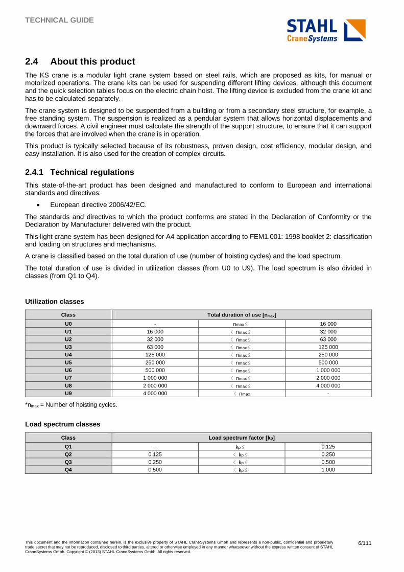
The total duration of use is divided in utilization classes (from U0 to U9). The load spectrum is also divided in classes (from Q1 to Q4).
Utilization classes
Class Total duration of use [n max]
U0 - nmax ≤ 16 000
U1 16 000 < nmax ≤ 32 000 U2 32 000 < nmax ≤ 63 000 U3 63 000 < nmax ≤ 125 000 U4 125 000 < nmax ≤ 250 000
U5 250 000 < nmax ≤ 500 000 U6 500 000 < nmax ≤ 1 000 000 U7 1 000 000 < nmax ≤ 2 000 000
U8 2 000 000 < nmax ≤ 4 000 000 U9 4 000 000 < nmax -
*nmax = Number of hoisting cycles.
Load spectrum classes
Class Load spectrum factor [k p]
Q1 - kp ≤ 0.125 Q2 0.125 < kp ≤ 0.250 Q3 0.250 < kp ≤ 0.500 Q4 0.500 < kp ≤ 1.000
TECHNICAL GUIDE
This document and the information contained herein, is the exclusive property of STAHL CraneSystems Gmbh and represents a non-public, confidential and proprietary trade secret that may not be reproduced, disclosed to third parties, altered or otherwise employed in any manner whatsoever without the express written consent of STAHL CraneSystems Gmbh. Copyright © (2013) STAHL CraneSystems Gmbh. All rights reserved.
7/111
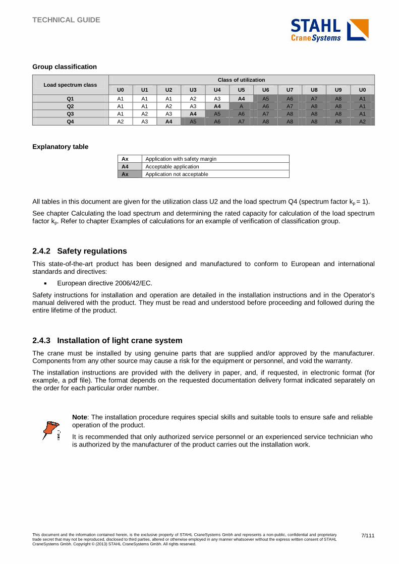
Group classification
Load spectrum class Class of utilization
U0 U1 U2 U3 U4 U5 U6 U7 U8 U9 U0
Q1 A1 A1 A1 A2 A3 A4 A5 A6 A7 A8 A1 Q2 A1 A1 A2 A3 A4 A A6 A7 A8 A8 A1 Q3 A1 A2 A3 A4 A5 A6 A7 A8 A8 A8 A1
Q4 A2 A3 A4 A5 A6 A7 A8 A8 A8 A8 A2
Explanatory table
Ax Application with safety margin
A4 Acceptable application Ax Application not acceptable
All tables in this document are given for the utilization class U2 and the load spectrum Q4 (spectrum factor kp = 1).
See chapter Calculating the load spectrum and determining the rated capacity for calculation of the load spectrum factor kp. Refer to chapter Examples of calculations for an example of verification of classification group.
2.4.2 Safety regulations
This state-of-the-art product has been designed and manufactured to conform to European and international standards and directives:
� European directive 2006/42/EC.
Safety instructions for installation and operation are detailed in the installation instructions and in the Operator’s manual delivered with the product. They must be read and understood before proceeding and followed during the entire lifetime of the product.
2.4.3 Installation of light crane system
The crane must be installed by using genuine parts that are supplied and/or approved by the manufacturer. Components from any other source may cause a risk for the equipment or personnel, and void the warranty.
The installation instructions are provided with the delivery in paper, and, if requested, in electronic format (for example, a pdf file). The format depends on the requested documentation delivery format indicated separately on the order for each particular order number.
Note : The installation procedure requires special skills and suitable tools to ensure safe and reliable operation of the product.
It is recommended that only authorized service personnel or an experienced service technician who is authorized by the manufacturer of the product carries out the installation work.
TECHNICAL GUIDE
This document and the information contained herein, is the exclusive property of STAHL CraneSystems Gmbh and represents a non-public, confidential and proprietary trade secret that may not be reproduced, disclosed to third parties, altered or otherwise employed in any manner whatsoever without the express written consent of STAHL CraneSystems Gmbh. Copyright © (2013) STAHL CraneSystems Gmbh. All rights reserved.
8/111
2.4.4 Inspection, preventive maintenance
Light crane systems and monorails are built with modular components that require low maintenance. The fixing torque of the bolted connection sets must be checked periodically, similar to the condition of the safety components and wearing parts. The correct maintenance interval depends on the actual use of the crane, at a minimum once a year.
Inspection intervals
Utilization Interval Single shift usage Every 12 months
Double shift usage Every 8 months Three shift usage Every 6 months
Note : This table is a general guideline. The needed inspection interval may be shorter, depending on other factors, such as environmental conditions.
Note : Instructions for proper maintenance are included in the (crane) Operator’s manual.
TECHNICAL GUIDE
This document and the information contained herein, is the exclusive property of STAHL CraneSystems Gmbh and represents a non-public, confidential and proprietary trade secret that may not be reproduced, disclosed to third parties, altered or otherwise employed in any manner whatsoever without the express written consent of STAHL CraneSystems Gmbh. Copyright © (2013) STAHL CraneSystems Gmbh. All rights reserved.
9/111
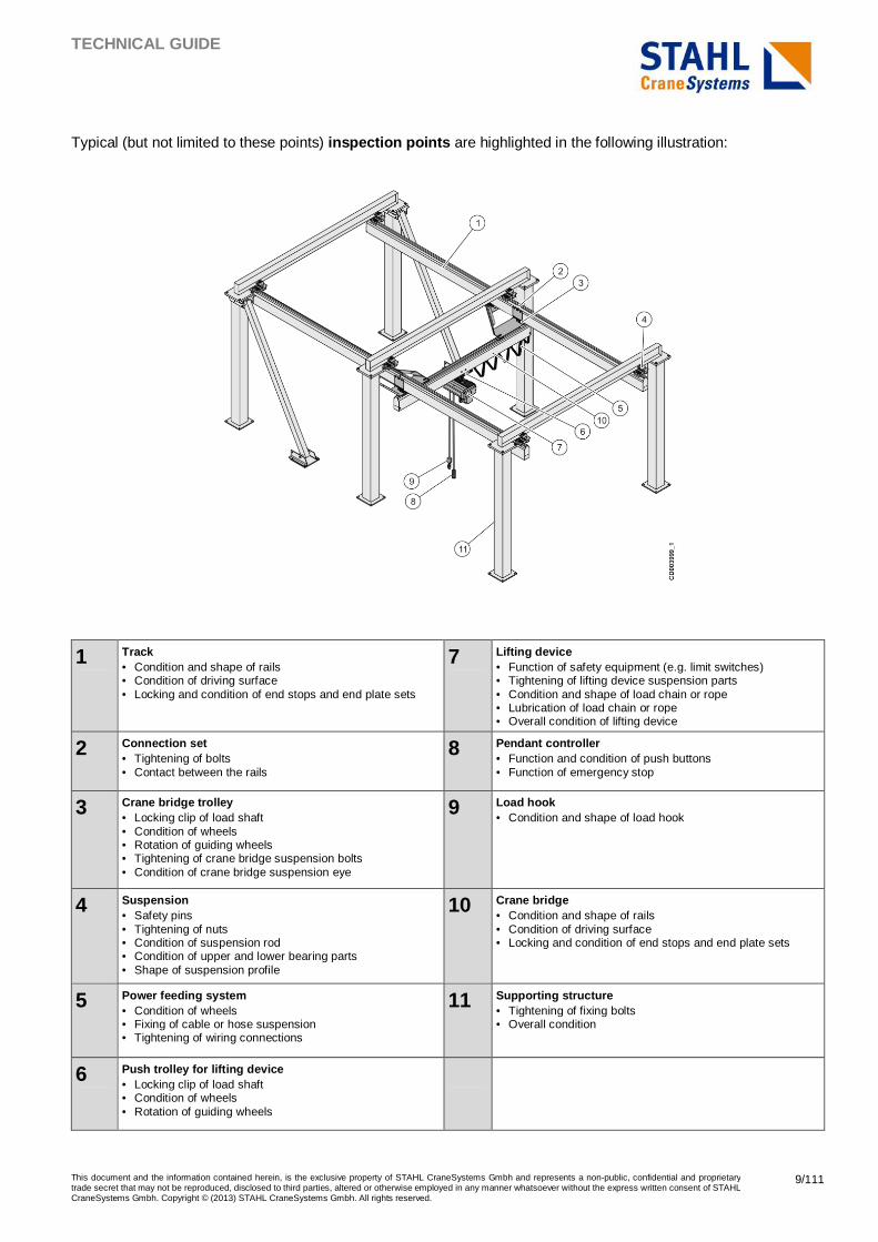
Typical (but not limited to these points) inspection points are highlighted in the following illustration:
1 Track • Condition and shape of rails • Condition of driving surface • Locking and condition of end stops and end plate sets
7 Lifting device • Function of safety equipment (e.g. limit switches) • Tightening of lifting device suspension parts • Condition and shape of load chain or rope • Lubrication of load chain or rope • Overall condition of lifting device
2 Connection set • Tightening of bolts • Contact between the rails
8 Pendant controller • Function and condition of push buttons • Function of emergency stop
3 Crane bridge trolley • Locking clip of load shaft • Condition of wheels • Rotation of guiding wheels • Tightening of crane bridge suspension bolts • Condition of crane bridge suspension eye
9 Load hook • Condition and shape of load hook
4 Suspension • Safety pins • Tightening of nuts • Condition of suspension rod • Condition of upper and lower bearing parts • Shape of suspension profile
10 Crane bridge • Condition and shape of rails • Condition of driving surface • Locking and condition of end stops and end plate sets
5 Power feeding system • Condition of wheels • Fixing of cable or hose suspension • Tightening of wiring connections
11 Supporting structure • Tightening of fixing bolts • Overall condition
6 Push trolley for lifting device • Locking clip of load shaft • Condition of wheels • Rotation of guiding wheels

TECHNICAL GUIDE
This document and the information contained herein, is the exclusive property of STAHL CraneSystems Gmbh and represents a non-public, confidential and proprietary trade secret that may not be reproduced, disclosed to third parties, altered or otherwise employed in any manner whatsoever without the express written consent of STAHL CraneSystems Gmbh. Copyright © (2013) STAHL CraneSystems Gmbh. All rights reserved.
10/111
2.4.5 Other relevant documents
Other documents that are related to the complete product selection or delivery are, for example:
� Crane Operator’s manual � Crane Assembly instructions � Spare part manual � Technical guide for the selected lifting device � Owner’s manual for the selected lifting device � Installation and service instructions for the selected lifting device � User instructions for sales configurator.
TECHNICAL GUIDE
This document and the information contained herein, is the exclusive property of STAHL CraneSystems Gmbh and represents a non-public, confidential and proprietary trade secret that may not be reproduced, disclosed to third parties, altered or otherwise employed in any manner whatsoever without the express written consent of STAHL CraneSystems Gmbh. Copyright © (2013) STAHL CraneSystems Gmbh. All rights reserved.
11/111
3 PRODUCT RANGE
3.1 Environmental conditions This product is designed for indoor use in typical industrial environments. Typical customer segments are, for example, the automotive industry and general manufacturing.
� Rated capacity range is up to 2000 kg. � Temperature range is from -10 °C to +40 °C. � Atmospheric corrosivity category is C2 according to EN ISO 12944-2.
Note : This document does not include products for Hazardous Environments (explosive atmosphere).
TECHNICAL GUIDE
This document and the information contained herein, is the exclusive property of STAHL CraneSystems Gmbh and represents a non-public, confidential and proprietary trade secret that may not be reproduced, disclosed to third parties, altered or otherwise employed in any manner whatsoever without the express written consent of STAHL CraneSystems Gmbh. Copyright © (2013) STAHL CraneSystems Gmbh. All rights reserved.
12/111
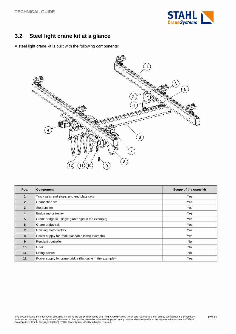
3.2 Steel light crane kit at a glance
A steel light crane kit is built with the following components:
Pos. Component Scope of the crane kit
1 Track rails, end stops, and end plate sets Yes
2 Connection set Yes
3 Suspension Yes
4 Bridge motor trolley Yes
5 Crane bridge kit (single girder rigid in the example) Yes
6 Crane bridge rail Yes
7 Hoisting motor trolley Yes
8 Power supply for track (flat cable in the example) Yes
9 Pendant controller No
10 Hook No
11 Lifting device No
12 Power supply for crane bridge (flat cable in the example) Yes
TECHNICAL GUIDE
This document and the information contained herein, is the exclusive property of STAHL CraneSystems Gmbh and represents a non-public, confidential and proprietary trade secret that may not be reproduced, disclosed to third parties, altered or otherwise employed in any manner whatsoever without the express written consent of STAHL CraneSystems Gmbh. Copyright © (2013) STAHL CraneSystems Gmbh. All rights reserved.
13/111
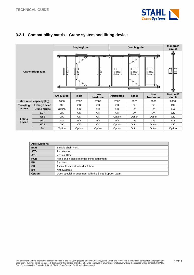
3.2.1 Compatibility matrix - Crane system and lifti ng device
Crane bridge type
Single girder Double girder Monorail/ circuit
Articulated Rigid Low headroom Articulated Rigid Low
headroom Monorail/
circuit Max. rated capacity [kg] 1600 2000 2000 2000 2000 2000 2000
Traveling motors
Lifting device OK OK OK OK OK OK OK
Crane bridge Option OK OK OK OK OK n/a
Lifting device
ECH OK OK OK OK OK OK OK
ATB OK OK OK Option Option Option OK
ATL n/a n/a n/a n/a n/a n/a n/a
HCB OK OK OK Option Option Option OK
BH Option Option Option Option Option Option Option
Abbreviations ECH Electric chain hoist ATB Air balancer
ATL Vertical lifter HCB Hand chain block (manual lifting equipment) BH Belt hoist OK Available as a standard solution
n/a Not available Option Upon special arrangement with the Sales Support team
TECHNICAL GUIDE
This document and the information contained herein, is the exclusive property of STAHL CraneSystems Gmbh and represents a non-public, confidential and proprietary trade secret that may not be reproduced, disclosed to third parties, altered or otherwise employed in any manner whatsoever without the express written consent of STAHL CraneSystems Gmbh. Copyright © (2013) STAHL CraneSystems Gmbh. All rights reserved.
14/111
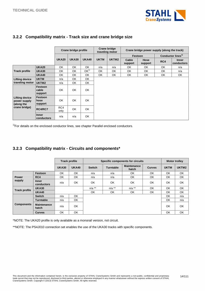
3.2.2 Compatibility matrix - Track size and crane b ridge size
Crane bridge profile Crane bridge traveling motor
Crane bridge power supply (along the track)
UKA20 UKA30 UKA40 UKTM UKTM2 Festoon Conductor lines 1)
Cable support
Hose support RC4 Inner
conductors
Track profile UKA20 OK OK OK n/a n/a OK OK OK n/a UKA30 OK OK OK1) OK OK OK OK OK n/a UKA40 OK OK OK OK OK OK OK OK OK
Lifting device traveling motor
UKTM n/a OK OK
UKTM2 n/a OK OK
Lifting device power supply (along the crane bridge)
Festoon cable support
OK OK OK
Festoon hose support
OK OK OK
RC4/RC7 RC4 only OK OK
Inner conductors
n/a n/a OK
1)For details on the enclosed conductor lines, see chapter Parallel enclosed conductors.
3.2.3 Compatibility matrix - Circuits and component s*
Track profile Specific components for circuits Motor trolley
UKA30 UKA40 Switch Turntable Maintenance hatch Curves UKTM UKTM2
Power supply
Festoon OK OK n/a n/a OK OK OK OK RC4 OK OK n/a n/a OK OK OK OK Inner conductors
n/a OK OK OK OK OK OK OK
Track profile UKA30
n/a ** n/a ** n/a ** OK OK OK
UKA40 OK OK OK OK OK OK
Components
Switch n/a OK
OK n/a Turntable n/a OK OK n/a
Maintenance hatch n/a OK OK OK
Curves OK OK OK OK
*NOTE: The UKA20 profile is only available as a monorail version, not circuit.
**NOTE: The PS4J010 connection set enables the use of the UKA30 tracks with specific components.
TECHNICAL GUIDE
This document and the information contained herein, is the exclusive property of STAHL CraneSystems Gmbh and represents a non-public, confidential and proprietary trade secret that may not be reproduced, disclosed to third parties, altered or otherwise employed in any manner whatsoever without the express written consent of STAHL CraneSystems Gmbh. Copyright © (2013) STAHL CraneSystems Gmbh. All rights reserved.
15/111
3.3 Suspended cranes (downward forces) Typically, cranes and monorails have only downward forces. With telescopic construction, or a combination of long outreach, high capacity, short span, it is possible that also upward forces occur. This document covers the downward forces. For information about upward forces, contact the Sales Support team.
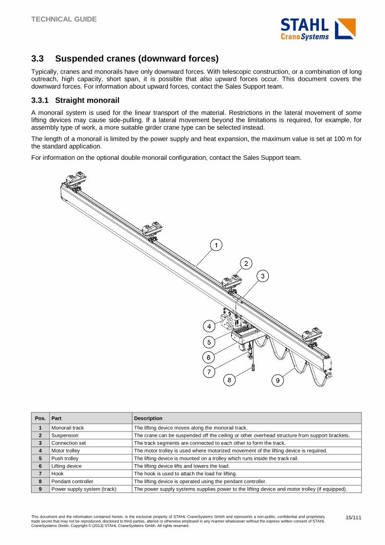
3.3.1 Straight monorail
A monorail system is used for the linear transport of the material. Restrictions in the lateral movement of some lifting devices may cause side-pulling. If a lateral movement beyond the limitations is required, for example, for assembly type of work, a more suitable girder crane type can be selected instead.
The length of a monorail is limited by the power supply and heat expansion, the maximum value is set at 100 m for the standard application.
For information on the optional double monorail configuration, contact the Sales Support team.
Pos. Part Description
1 Monorail track The lifting device moves along the monorail track.
2 Suspension The crane can be suspended off the ceiling or other overhead structure from support brackets.
3 Connection set The track segments are connected to each other to form the track.
4 Motor trolley The motor trolley is used where motorized movement of the lifting device is required.
5 Push trolley The lifting device is mounted on a trolley which runs inside the track rail.
6 Lifting device The lifting device lifts and lowers the load.
7 Hook The hook is used to attach the load for lifting.
8 Pendant controller The lifting device is operated using the pendant controller.
9 Power supply system (track) The power supply systems supplies power to the lifting device and motor trolley (if equipped).
TECHNICAL GUIDE
This document and the information contained herein, is the exclusive property of STAHL CraneSystems Gmbh and represents a non-public, confidential and proprietary trade secret that may not be reproduced, disclosed to third parties, altered or otherwise employed in any manner whatsoever without the express written consent of STAHL CraneSystems Gmbh. Copyright © (2013) STAHL CraneSystems Gmbh. All rights reserved.
16/111
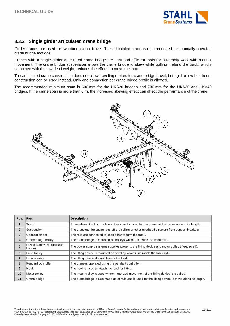
3.3.2 Single girder articulated crane bridge
Girder cranes are used for two-dimensional travel. The articulated crane is recommended for manually operated crane bridge motions.
Cranes with a single girder articulated crane bridge are light and efficient tools for assembly work with manual movement. The crane bridge suspension allows the crane bridge to skew while pulling it along the track, which, combined with the low dead weight, reduces the efforts to move the load.
The articulated crane construction does not allow traveling motors for crane bridge travel, but rigid or low headroom construction can be used instead. Only one connection per crane bridge profile is allowed.
The recommended minimum span is 600 mm for the UKA20 bridges and 700 mm for the UKA30 and UKA40 bridges. If the crane span is more than 6 m, the increased skewing effect can affect the performance of the crane.
Pos. Part Description
1 Track An overhead track is made up of rails and is used for the crane bridge to move along its length.
2 Suspension The crane can be suspended off the ceiling or other overhead structure from support brackets.
3 Connection set The rails are connected to each other to form the track.
4 Crane bridge trolley The crane bridge is mounted on trolleys which run inside the track rails.
5 Power supply system (crane bridge) The power supply systems supplies power to the lifting device and motor trolley (if equipped).
6 Push trolley The lifting device is mounted on a trolley which runs inside the track rail.
7 Lifting device The lifting device lifts and lowers the load.
8 Pendant controller The crane is operated using the pendant controller.
9 Hook The hook is used to attach the load for lifting.
10 Motor trolley The motor trolley is used where motorized movement of the lifting device is required.
11 Crane bridge The crane bridge is also made up of rails and is used for the lifting device to move along its length.
TECHNICAL GUIDE
This document and the information contained herein, is the exclusive property of STAHL CraneSystems Gmbh and represents a non-public, confidential and proprietary trade secret that may not be reproduced, disclosed to third parties, altered or otherwise employed in any manner whatsoever without the express written consent of STAHL CraneSystems Gmbh. Copyright © (2013) STAHL CraneSystems Gmbh. All rights reserved.
17/111
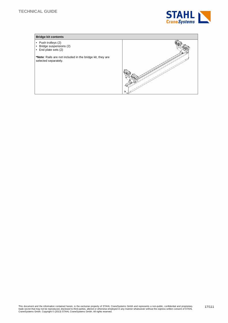
Bridge kit contents
• Push trolleys (2) • Bridge suspensions (2) • End plate sets (2) *Note : Rails are not included in the bridge kit, they are selected separately.
TECHNICAL GUIDE
This document and the information contained herein, is the exclusive property of STAHL CraneSystems Gmbh and represents a non-public, confidential and proprietary trade secret that may not be reproduced, disclosed to third parties, altered or otherwise employed in any manner whatsoever without the express written consent of STAHL CraneSystems Gmbh. Copyright © (2013) STAHL CraneSystems Gmbh. All rights reserved.
18/111
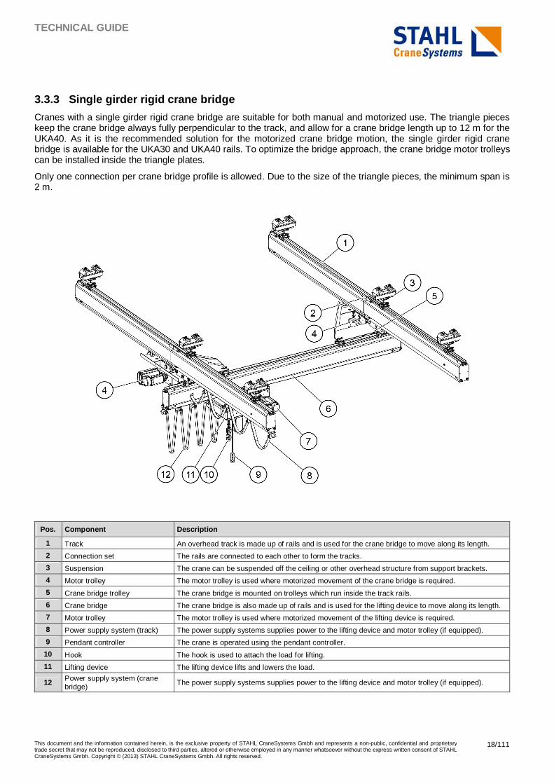
3.3.3 Single girder rigid crane bridge
Cranes with a single girder rigid crane bridge are suitable for both manual and motorized use. The triangle pieces keep the crane bridge always fully perpendicular to the track, and allow for a crane bridge length up to 12 m for the UKA40. As it is the recommended solution for the motorized crane bridge motion, the single girder rigid crane bridge is available for the UKA30 and UKA40 rails. To optimize the bridge approach, the crane bridge motor trolleys can be installed inside the triangle plates.
Only one connection per crane bridge profile is allowed. Due to the size of the triangle pieces, the minimum span is 2 m.
Pos. Component Description
1 Track An overhead track is made up of rails and is used for the crane bridge to move along its length.
2 Connection set The rails are connected to each other to form the tracks.
3 Suspension The crane can be suspended off the ceiling or other overhead structure from support brackets.
4 Motor trolley The motor trolley is used where motorized movement of the crane bridge is required.
5 Crane bridge trolley The crane bridge is mounted on trolleys which run inside the track rails.
6 Crane bridge The crane bridge is also made up of rails and is used for the lifting device to move along its length.
7 Motor trolley The motor trolley is used where motorized movement of the lifting device is required.
8 Power supply system (track) The power supply systems supplies power to the lifting device and motor trolley (if equipped).
9 Pendant controller The crane is operated using the pendant controller.
10 Hook The hook is used to attach the load for lifting.
11 Lifting device The lifting device lifts and lowers the load.
12 Power supply system (crane bridge) The power supply systems supplies power to the lifting device and motor trolley (if equipped).
TECHNICAL GUIDE
This document and the information contained herein, is the exclusive property of STAHL CraneSystems Gmbh and represents a non-public, confidential and proprietary trade secret that may not be reproduced, disclosed to third parties, altered or otherwise employed in any manner whatsoever without the express written consent of STAHL CraneSystems Gmbh. Copyright © (2013) STAHL CraneSystems Gmbh. All rights reserved.
19/111
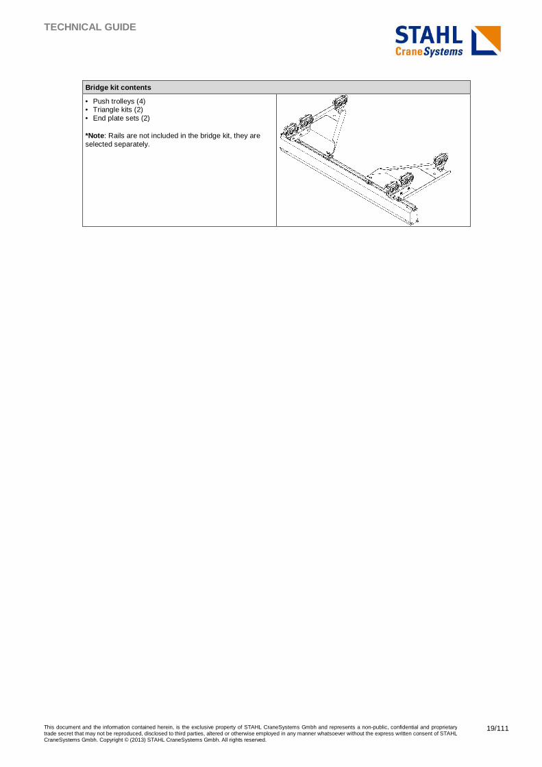
Bridge kit contents
• Push trolleys (4) • Triangle kits (2) • End plate sets (2) *Note : Rails are not included in the bridge kit, they are selected separately.
TECHNICAL GUIDE
This document and the information contained herein, is the exclusive property of STAHL CraneSystems Gmbh and represents a non-public, confidential and proprietary trade secret that may not be reproduced, disclosed to third parties, altered or otherwise employed in any manner whatsoever without the express written consent of STAHL CraneSystems Gmbh. Copyright © (2013) STAHL CraneSystems Gmbh. All rights reserved.
20/111
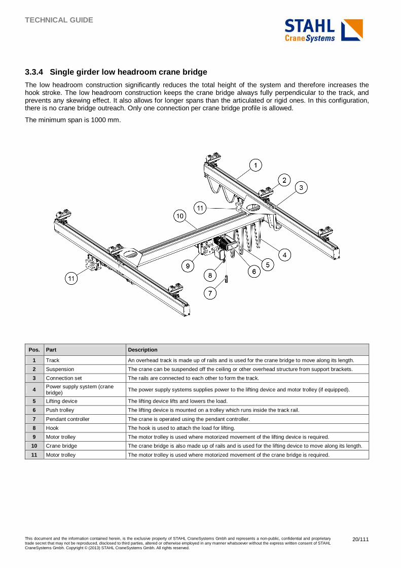
3.3.4 Single girder low headroom crane bridge
The low headroom construction significantly reduces the total height of the system and therefore increases the hook stroke. The low headroom construction keeps the crane bridge always fully perpendicular to the track, and prevents any skewing effect. It also allows for longer spans than the articulated or rigid ones. In this configuration, there is no crane bridge outreach. Only one connection per crane bridge profile is allowed.
The minimum span is 1000 mm.
Pos. Part Description
1 Track An overhead track is made up of rails and is used for the crane bridge to move along its length.
2 Suspension The crane can be suspended off the ceiling or other overhead structure from support brackets.
3 Connection set The rails are connected to each other to form the track.
4 Power supply system (crane bridge) The power supply systems supplies power to the lifting device and motor trolley (if equipped).
5 Lifting device The lifting device lifts and lowers the load.
6 Push trolley The lifting device is mounted on a trolley which runs inside the track rail.
7 Pendant controller The crane is operated using the pendant controller.
8 Hook The hook is used to attach the load for lifting.
9 Motor trolley The motor trolley is used where motorized movement of the lifting device is required.
10 Crane bridge The crane bridge is also made up of rails and is used for the lifting device to move along its length.
11 Motor trolley The motor trolley is used where motorized movement of the crane bridge is required.
TECHNICAL GUIDE
This document and the information contained herein, is the exclusive property of STAHL CraneSystems Gmbh and represents a non-public, confidential and proprietary trade secret that may not be reproduced, disclosed to third parties, altered or otherwise employed in any manner whatsoever without the express written consent of STAHL CraneSystems Gmbh. Copyright © (2013) STAHL CraneSystems Gmbh. All rights reserved.
21/111
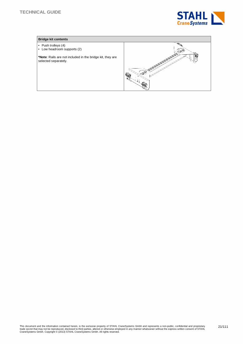
Bridge kit contents
• Push trolleys (4) • Low headroom supports (2) *Note : Rails are not included in the bridge kit, they are selected separately.
TECHNICAL GUIDE
This document and the information contained herein, is the exclusive property of STAHL CraneSystems Gmbh and represents a non-public, confidential and proprietary trade secret that may not be reproduced, disclosed to third parties, altered or otherwise employed in any manner whatsoever without the express written consent of STAHL CraneSystems Gmbh. Copyright © (2013) STAHL CraneSystems Gmbh. All rights reserved.
22/111
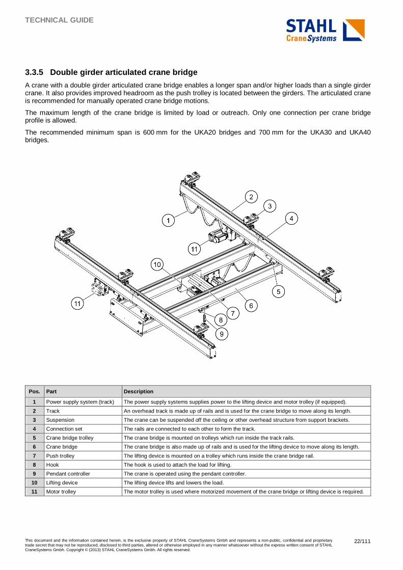
3.3.5 Double girder articulated crane bridge
A crane with a double girder articulated crane bridge enables a longer span and/or higher loads than a single girder crane. It also provides improved headroom as the push trolley is located between the girders. The articulated crane is recommended for manually operated crane bridge motions.
The maximum length of the crane bridge is limited by load or outreach. Only one connection per crane bridge profile is allowed.
The recommended minimum span is 600 mm for the UKA20 bridges and 700 mm for the UKA30 and UKA40 bridges.
Pos. Part Description
1 Power supply system (track) The power supply systems supplies power to the lifting device and motor trolley (if equipped).
2 Track An overhead track is made up of rails and is used for the crane bridge to move along its length.
3 Suspension The crane can be suspended off the ceiling or other overhead structure from support brackets.
4 Connection set The rails are connected to each other to form the track.
5 Crane bridge trolley The crane bridge is mounted on trolleys which run inside the track rails.
6 Crane bridge The crane bridge is also made up of rails and is used for the lifting device to move along its length.
7 Push trolley The lifting device is mounted on a trolley which runs inside the crane bridge rail.
8 Hook The hook is used to attach the load for lifting.
9 Pendant controller The crane is operated using the pendant controller.
10 Lifting device The lifting device lifts and lowers the load.
11 Motor trolley The motor trolley is used where motorized movement of the crane bridge or lifting device is required.
TECHNICAL GUIDE
This document and the information contained herein, is the exclusive property of STAHL CraneSystems Gmbh and represents a non-public, confidential and proprietary trade secret that may not be reproduced, disclosed to third parties, altered or otherwise employed in any manner whatsoever without the express written consent of STAHL CraneSystems Gmbh. Copyright © (2013) STAHL CraneSystems Gmbh. All rights reserved.
23/111
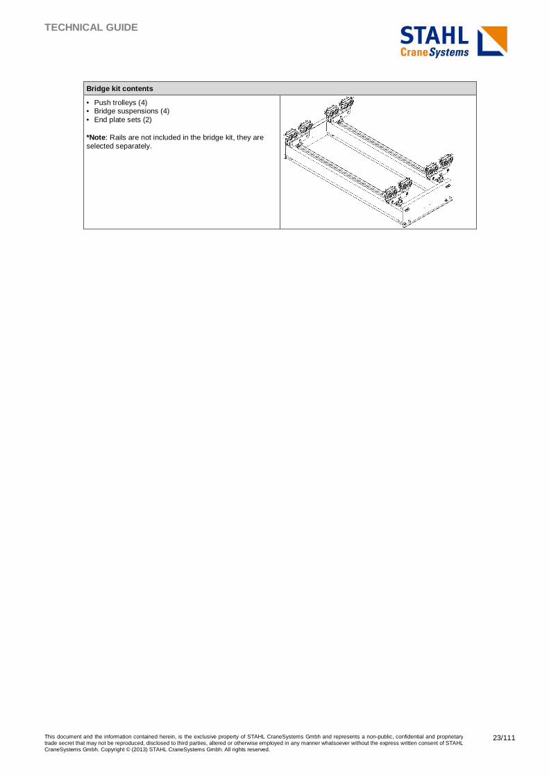
Bridge kit contents
• Push trolleys (4) • Bridge suspensions (4) • End plate sets (2) *Note : Rails are not included in the bridge kit, they are selected separately.
TECHNICAL GUIDE
This document and the information contained herein, is the exclusive property of STAHL CraneSystems Gmbh and represents a non-public, confidential and proprietary trade secret that may not be reproduced, disclosed to third parties, altered or otherwise employed in any manner whatsoever without the express written consent of STAHL CraneSystems Gmbh. Copyright © (2013) STAHL CraneSystems Gmbh. All rights reserved.
24/111
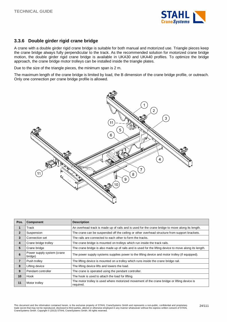
3.3.6 Double girder rigid crane bridge
A crane with a double girder rigid crane bridge is suitable for both manual and motorized use. Triangle pieces keep the crane bridge always fully perpendicular to the track. As the recommended solution for motorized crane bridge motion, the double girder rigid crane bridge is available in UKA30 and UKA40 profiles. To optimize the bridge approach, the crane bridge motor trolleys can be installed inside the triangle plates.
Due to the size of the triangle pieces, the minimum span is 2 m.
The maximum length of the crane bridge is limited by load, the B dimension of the crane bridge profile, or outreach. Only one connection per crane bridge profile is allowed.
Pos. Component Description
1 Track An overhead track is made up of rails and is used for the crane bridge to move along its length.
2 Suspension The crane can be suspended off the ceiling or other overhead structure from support brackets.
3 Connection set The rails are connected to each other to form the tracks.
4 Crane bridge trolley The crane bridge is mounted on trolleys which run inside the track rails.
5 Crane bridge The crane bridge is also made up of rails and is used for the lifting device to move along its length.
6 Power supply system (crane bridge) The power supply systems supplies power to the lifting device and motor trolley (if equipped).
7 Push trolley The lifting device is mounted on a trolley which runs inside the crane bridge rail.
8 Lifting device The lifting device lifts and lowers the load.
9 Pendant controller The crane is operated using the pendant controller.
10 Hook The hook is used to attach the load for lifting.
11 Motor trolley The motor trolley is used where motorized movement of the crane bridge or lifting device is required.
TECHNICAL GUIDE
This document and the information contained herein, is the exclusive property of STAHL CraneSystems Gmbh and represents a non-public, confidential and proprietary trade secret that may not be reproduced, disclosed to third parties, altered or otherwise employed in any manner whatsoever without the express written consent of STAHL CraneSystems Gmbh. Copyright © (2013) STAHL CraneSystems Gmbh. All rights reserved.
25/111
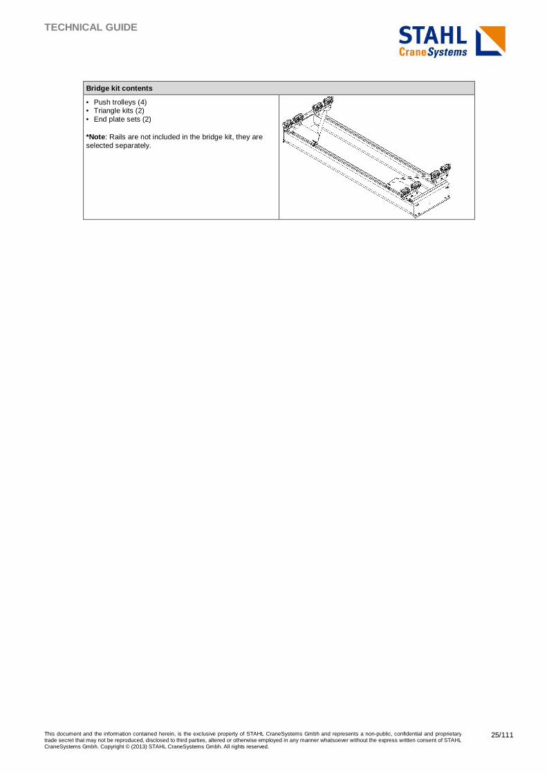
Bridge kit contents
• Push trolleys (4) • Triangle kits (2) • End plate sets (2) *Note : Rails are not included in the bridge kit, they are selected separately.
TECHNICAL GUIDE
This document and the information contained herein, is the exclusive property of STAHL CraneSystems Gmbh and represents a non-public, confidential and proprietary trade secret that may not be reproduced, disclosed to third parties, altered or otherwise employed in any manner whatsoever without the express written consent of STAHL CraneSystems Gmbh. Copyright © (2013) STAHL CraneSystems Gmbh. All rights reserved.
26/111
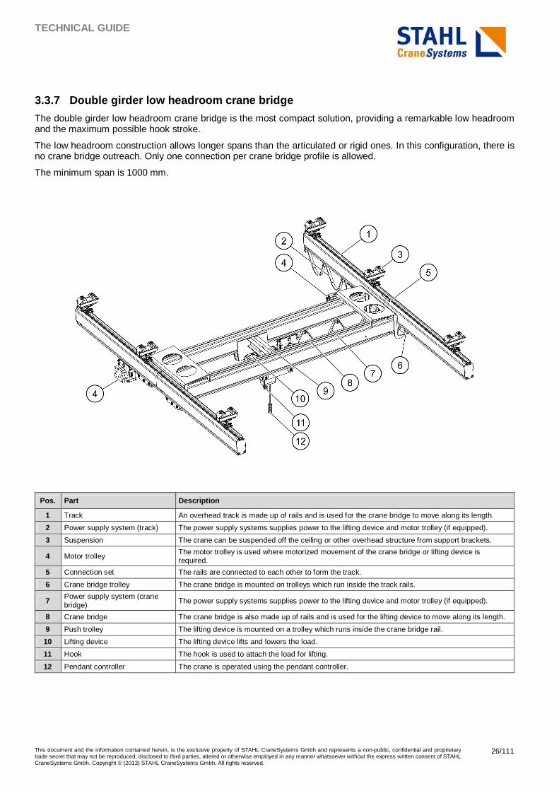
3.3.7 Double girder low headroom crane bridge
The double girder low headroom crane bridge is the most compact solution, providing a remarkable low headroom and the maximum possible hook stroke.
The low headroom construction allows longer spans than the articulated or rigid ones. In this configuration, there is no crane bridge outreach. Only one connection per crane bridge profile is allowed.
The minimum span is 1000 mm.
Pos. Part Description
1 Track An overhead track is made up of rails and is used for the crane bridge to move along its length.
2 Power supply system (track) The power supply systems supplies power to the lifting device and motor trolley (if equipped).
3 Suspension The crane can be suspended off the ceiling or other overhead structure from support brackets.
4 Motor trolley The motor trolley is used where motorized movement of the crane bridge or lifting device is required.
5 Connection set The rails are connected to each other to form the track.
6 Crane bridge trolley The crane bridge is mounted on trolleys which run inside the track rails.
7 Power supply system (crane bridge) The power supply systems supplies power to the lifting device and motor trolley (if equipped).
8 Crane bridge The crane bridge is also made up of rails and is used for the lifting device to move along its length.
9 Push trolley The lifting device is mounted on a trolley which runs inside the crane bridge rail.
10 Lifting device The lifting device lifts and lowers the load.
11 Hook The hook is used to attach the load for lifting.
12 Pendant controller The crane is operated using the pendant controller.
TECHNICAL GUIDE
This document and the information contained herein, is the exclusive property of STAHL CraneSystems Gmbh and represents a non-public, confidential and proprietary trade secret that may not be reproduced, disclosed to third parties, altered or otherwise employed in any manner whatsoever without the express written consent of STAHL CraneSystems Gmbh. Copyright © (2013) STAHL CraneSystems Gmbh. All rights reserved.
27/111
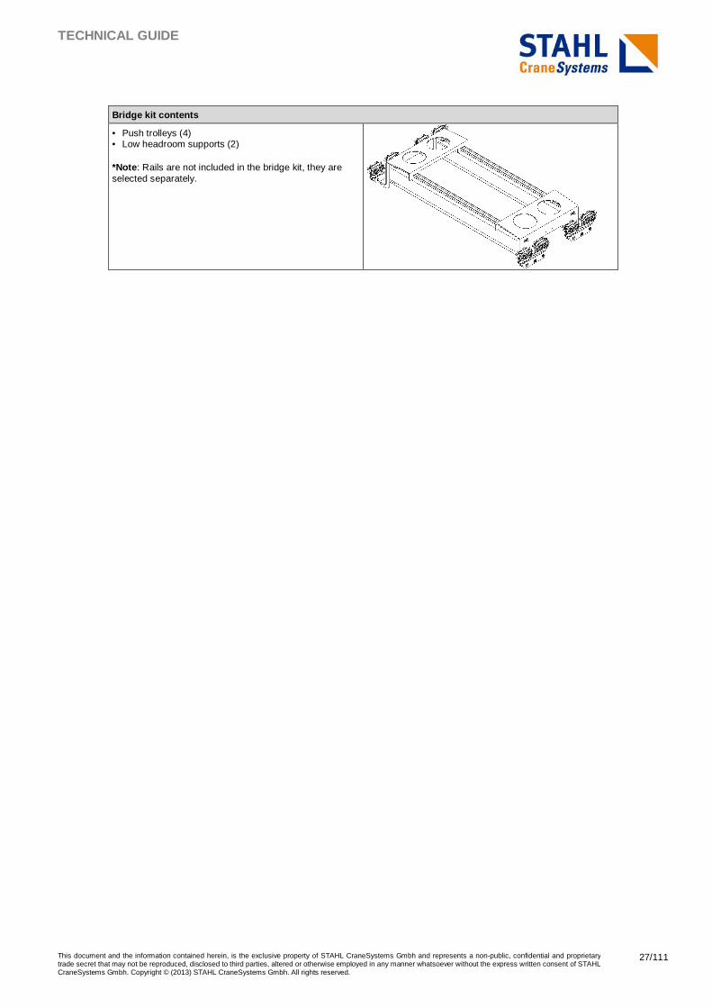
Bridge kit contents
• Push trolleys (4) • Low headroom supports (2) *Note : Rails are not included in the bridge kit, they are selected separately.
TECHNICAL GUIDE
This document and the information contained herein, is the exclusive property of STAHL CraneSystems Gmbh and represents a non-public, confidential and proprietary trade secret that may not be reproduced, disclosed to third parties, altered or otherwise employed in any manner whatsoever without the express written consent of STAHL CraneSystems Gmbh. Copyright © (2013) STAHL CraneSystems Gmbh. All rights reserved.
28/111
3.4 Advanced suspended cranes
3.4.1 Circuit monorails
It is possible to build non-straight monorails by using components like curves, switches, and turntables. Refer to chapter Components for circuits and monorails for data about these components.
Every circuit must be subject to a specific design study. The study is needed to check the feasibility, specify the rail lengths, define the suspension locations, and to ensure that the final product is in good shape. A list of input data has to be completed before starting any study.
For more information about this option, contact the Sales Support team.
3.4.2 Long outreach crane bridges
As a standard solution in normal circumstances, and for safety reasons, the load and the lifting device should always be located inside the crane area (between the tracks). However, it is possible to extend the girder of the articulated and rigid crane bridges for the festoon storage area. This possibility is limited to the maximal length of the rails, as only one connection is allowed on the bridge girders.
For more information about this option, contact the Sales Support team.
3.4.3 Telescopic crane bridges
The telescopic crane allows a greater outreach through a second girder moving under the main girder crane. This solution can be required when it is not possible to place the track above the lifting or lowering position of the load. The purpose of the solution is to lift or lower the load out of the span. The load must be moved inside the span area to allow a long travel.
For more information about this option, contact the Sales Support team.
3.4.4 Extended cross travel crane bridges
In situations where a remarkable long travel distance is required for the crane bridge, specific arrangements with three tracks are possible. In this case, the rigid motorized crane bridges are mandatory.
For more information about this option, contact the Sales Support team.
3.4.5 Energy power supply by inner conductors insid e UKA40 rails
As a standard variant, the power supply is provided through a festoon cable under the profile or through parallel enclosed conductor lines. As an option, the power supply can be achieved with inner conductors inside the UKA40 rails.
This solution, called the UKA40-S, provides a versatile power supply. It can be used especially for the circuit monorails that are fitted with switches and turntables, for the use in situations where other power supply solutions cannot be used. It can be used as well in systems with more than two crane bridges under the track.
For more information about this option, contact the Sales Support team.
3.4.6 Redundant safety
When intensive operation of the cranes is required, under conditions where the customer does not allow the interruption of the working area, it is possible to install safety redundant devices on the articulated single girder bridges and on the suspensions. Other bridge types are safety redundant by design, as each bridge trolley is linked to the track by at least two push trolleys.
For detailed information about this option, contact the Sales Support team.
TECHNICAL GUIDE
This document and the information contained herein, is the exclusive property of STAHL CraneSystems Gmbh and represents a non-public, confidential and proprietary trade secret that may not be reproduced, disclosed to third parties, altered or otherwise employed in any manner whatsoever without the express written consent of STAHL CraneSystems Gmbh. Copyright © (2013) STAHL CraneSystems Gmbh. All rights reserved.
29/111
4 LIGHT CRANE SYSTEM CONFIGURATION
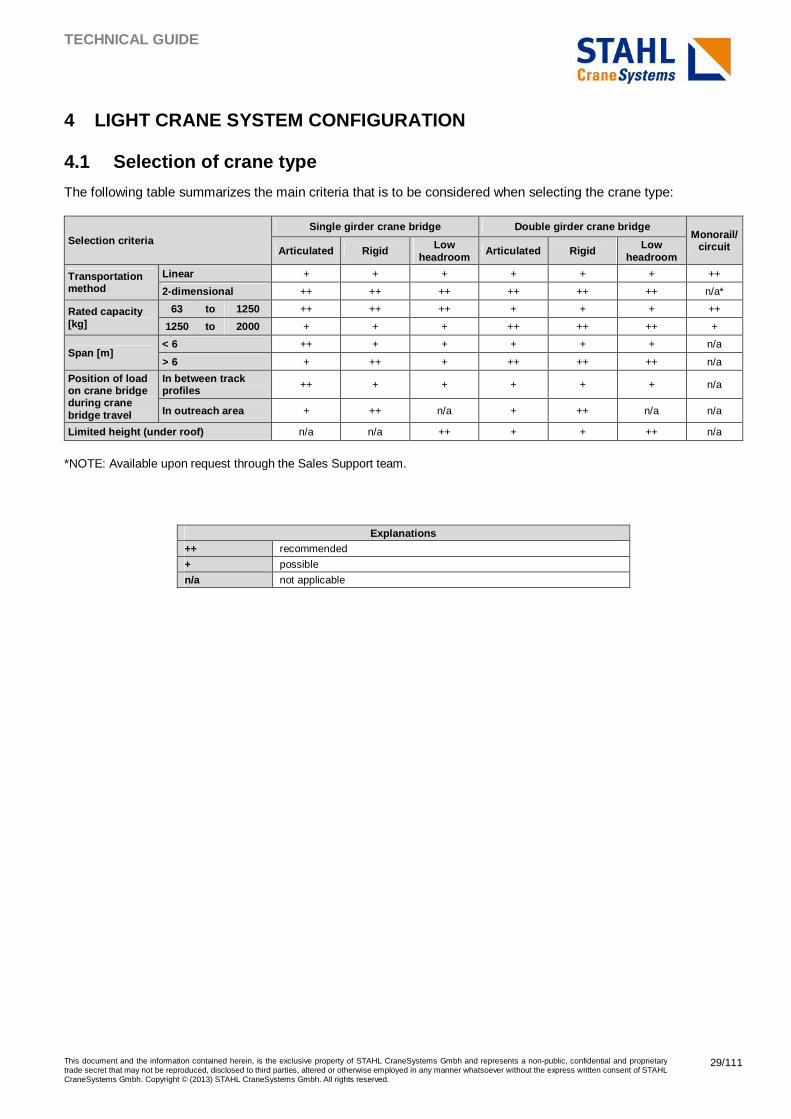
4.1 Selection of crane type
The following table summarizes the main criteria that is to be considered when selecting the crane type:
Selection criteria Single girder crane bridge Double girder crane bridge
Monorail/circuit Articulated Rigid Low
headroom Articulated Rigid Low
headroom
Transportation method
Linear + + + + + + ++
2-dimensional ++ ++ ++ ++ ++ ++ n/a*
Rated capacity [kg]
63 to 1250 ++ ++ ++ + + + ++
1250 to 2000 + + + ++ ++ ++ +
Span [m] < 6 ++ + + + + + n/a
> 6 + ++ + ++ ++ ++ n/a
Position of load on crane bridge during crane bridge travel
In between track profiles ++ + + + + + n/a
In outreach area + ++ n/a + ++ n/a n/a
Limited height (under roof) n/a n/a ++ + + ++ n/a
*NOTE: Available upon request through the Sales Support team.
Explanations
++ recommended
+ possible
n/a not applicable
TECHNICAL GUIDE
This document and the information contained herein, is the exclusive property of STAHL CraneSystems Gmbh and represents a non-public, confidential and proprietary trade secret that may not be reproduced, disclosed to third parties, altered or otherwise employed in any manner whatsoever without the express written consent of STAHL CraneSystems Gmbh. Copyright © (2013) STAHL CraneSystems Gmbh. All rights reserved.
30/111
4.2 Quick selection Quick selection helps with quickly determining the required profile sizes for the crane.
Note : The results of the quick selection must be evaluated with the sales configurator.
Note : The quick selection tables and the graphs for determining the rail type are based on an outreach of 150 mm. It means that the load is always located between the track profiles.
The outreach can be extended for storing the festoon trolleys. See chapter Festoon under profile for the calculation of the number of the festoon trolleys required.
For longer load-supporting outreaches, contact the Sales Support team.
Note : For limitations on the hook approach, see the following chapters of this document:
• Chapter Crane dimensions for the minimum distance between the hook and the end of the rail.
• Chapter Energy supply for details regarding the space requirements for energy supply.
The measurements were calculated considering a predetermined lifting device weight. If a different lifting device weight or crane span is needed, the detailed calculations in the following chapter must be executed.
All given values are maximum values, and they are given in millimeters [mm]. The deflection criteria that are used is L/500.
The quick selection tables and graphs are applicable for single bridge configurations. For configurations with multiple bridges, contact the Sales Support team.
TECHNICAL GUIDE
This document and the information contained herein, is the exclusive property of STAHL CraneSystems Gmbh and represents a non-public, confidential and proprietary trade secret that may not be reproduced, disclosed to third parties, altered or otherwise employed in any manner whatsoever without the express written consent of STAHL CraneSystems Gmbh. Copyright © (2013) STAHL CraneSystems Gmbh. All rights reserved.
31/111
4.2.1 Single girder crane bridges
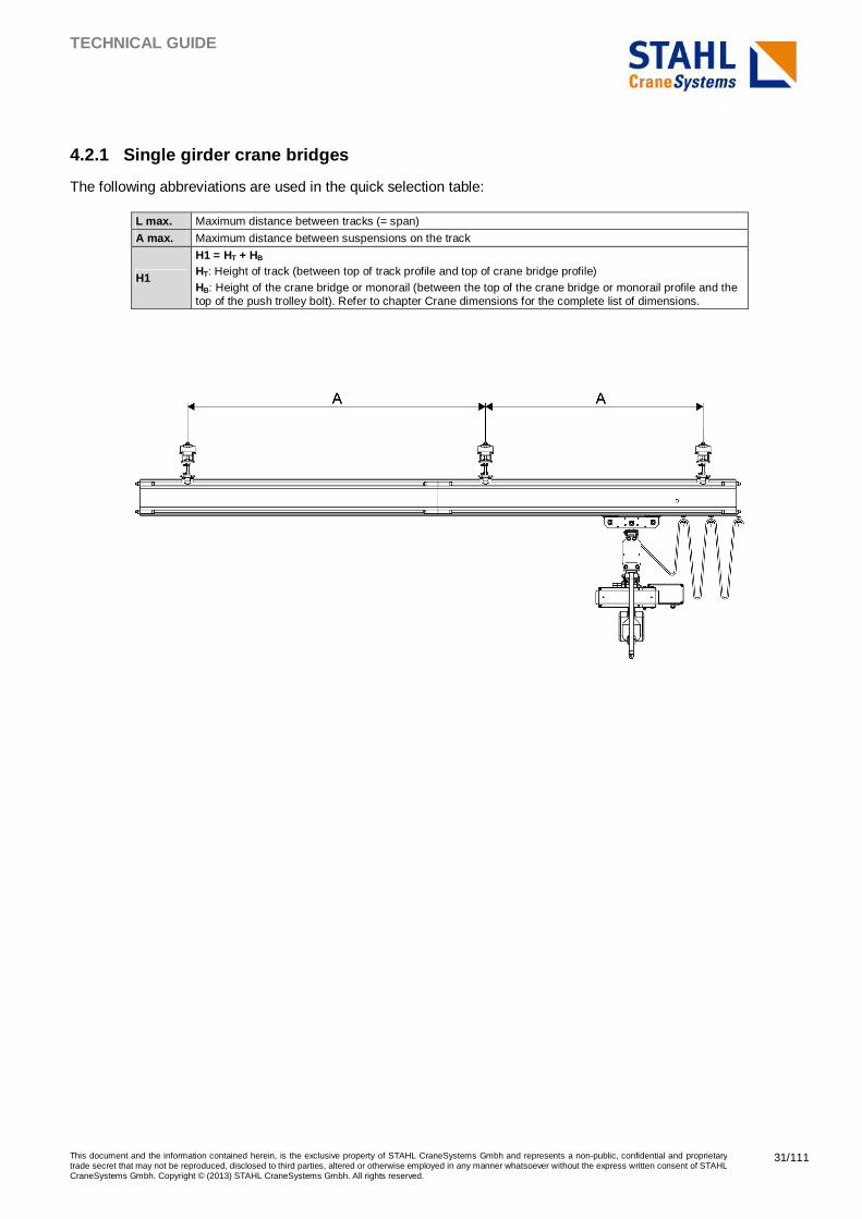
The following abbreviations are used in the quick selection table:
L max. Maximum distance between tracks (= span)
A max. Maximum distance between suspensions on the track
H1
H1 = HT + HB HT: Height of track (between top of track profile and top of crane bridge profile) HB: Height of the crane bridge or monorail (between the top of the crane bridge or monorail profile and the top of the push trolley bolt). Refer to chapter Crane dimensions for the complete list of dimensions.
TECHNICAL GUIDE
This document and the information contained herein, is the exclusive property of STAHL CraneSystems Gmbh and represents a non-public, confidential and proprietary trade secret that may not be reproduced, disclosed to third parties, altered or otherwise employed in any manner whatsoever without the express written consent of STAHL CraneSystems Gmbh. Copyright © (2013) STAHL CraneSystems Gmbh. All rights reserved.
32/111
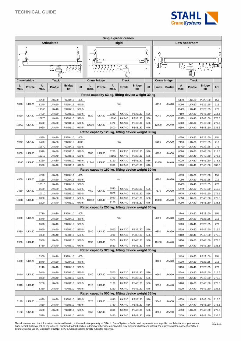
Single girder cranes
Articulated Rigid Low headroom
Crane bridge Track Crane bridge Track Crane bridge Track
L max. Profile A
max. Profile Bridge kit H1 L
max. Profile A max. Profile Bridge
kit H1 L max. Profile A max. Profile Bridge
kit H1
Rated capacity 63 kg, lifting device weight 30 kg
5890 UKA20
5290 UKA20 PS2B410 405
n/a 6110 UKA20
5170 UKA20 PS2B160 151
8240 UKA30 PS2B415 470.5 8090 UKA30 PS2B165 216
11560 UKA40 PS2B415 530.5 11430 UKA40 PS2B165 276
8820 UKA30 7490 UKA30 PS3B110 520.5
8820 UKA30 7310 UKA30 PS3B130 526
9040 UKA30 7150 UKA30 PS4B160 216.5
10870 UKA40 PS3B110 580.5 10690 UKA40 PS3B130 586 10530 UKA40 PS4B160 276.5
12060 UKA40 6600 UKA30 PS4B110 580.5
12060 UKA40 6470 UKA30 PS4B130 586
12280 UKA40 6360 UKA30 PS4B160 276.5
9950 UKA40 PS4B110 640.5 9800 UKA40 PS4B130 646 9680 UKA40 PS4B160 336.5
Rated capacity 125 kg, lifting device weight 30 kg
4940 UKA20
4590 UKA20 PS2B410 405
n/a 5160 UKA20
4550 UKA20 PS2B160 151
7490 UKA30 PS2B415 4705 7410 UKA30 PS2B165 216
10870 UKA40 PS2B415 530.5 10790 UKA40 PS2B165 276
7880 UKA30 6940 UKA30 PS3B110 520.5
7880 UKA30 6790 UKA30 PS3B130 526
8100 UKA30 6680 UKA30 PS4B160 216.5
10310 UKA40 PS3B110 580.5 10160 UKA40 PS3B130 586 10030 UKA40 PS4B160 276.5
11240 UKA40 6220 UKA30 PS4B110 580.5
11240 UKA40 6110 UKA30 PS4B130 586
11460 UKA40 6020 UKA30 PS4B160 276.5
9520 UKA40 PS4B110 640.5 9390 UKA40 PS4B130 646 9290 UKA40 PS4B160 336.5
Rated capacity 160 kg, lifting device weight 30 kg
4560 UKA20
4290 UKA20 PS2B410 405
n/a 4780 UKA20
4270 UKA20 PS2B160 151
7130 UKA30 PS2B415 470.5 7090 UKA30 PS2B165 216
10510 UKA40 PS2B415 530.5 10460 UKA40 PS2B165 276
7450 UKA30 6660 UKA30 PS3B110 520.5
7450 UKA30 6530 UKA30 PS3B130 526
7670 UKA30 6440 UKA30 PS4B160 216.5
10010 UKA40 PS3B110 580.5 9870 UKA40 PS3B130 586 9770 UKA40 PS4B160 276.5
10830 UKA40 6020 UKA30 PS4B110 580.5
10830 UKA40 5920 UKA30 PS4B130 586
11050 UKA40 5850 UKA30 PS4B160 276.5
9290 UKA40 PS4B110 640.5 9170 UKA40 PS4B130 646 9090 UKA40 PS4B160 336.5
Rated capacity 250 kg, lifting device weight 30 kg
3870 UKA20
3710 UKA20 PS2B410 405
n/a 4090 UKA20
3740 UKA20 PS2B160 151
6370 UKA30 PS2B415 470.5 6390 UKA30 PS2B165 216
9690 UKA40 PS2B415 530.5 9720 UKA40 PS2B165 276
6580 UKA30 6050 UKA30 PS3B110 520.5
6580 UKA30 5950 UKA30 PS3B130 526
6800 UKA30 5910 UKA30 PS4B160 216.5
9330 UKA40 PS3B110 580.5 9210 UKA40 PS3B130 586 9160 UKA40 PS4B160 276.5
9930 UKA40 5580 UKA30 PS4B110 580.5
9930 UKA40 5500 UKA30 PS4B130 586
10150 UKA40 5450 UKA30 PS4B160 276.5
8750 UKA40 PS4B110 640.5 8650 UKA40 PS4B130 646 8590 UKA40 PS4B160 336.5
Rated capacity 320 kg, lifting device weight 35 kg
3480 UKA20
3360 UKA20 PS2B410 405
3700 UKA20
3420 UKA20 PS2B160 151
5870 UKA30 PS2B415 470.5 5930 UKA30 PS2B165 216
9110 UKA40 PS2B415 530.5 9190 UKA40 PS2B165 276
6040 UKA30 5640 UKA30 PS3B110 520.5
6040 UKA30 5560 UKA30 PS3B130 526
6260 UKA30 5540 UKA30 PS4B160 216.5
8830 UKA40 PS3B110 580.5 8730 UKA40 PS3B130 586 8710 UKA40 PS4B160 276.5
9310 UKA40 5260 UKA30 PS4B110 580.5
9310 UKA40 5190 UKA30 PS4B130 586
9530 UKA40 5160 UKA30 PS4B160 276.5
8350 UKA40 PS4B110 640.5 8260 UKA40 PS4B130 646 8220 UKA40 PS4B160 336.5
Rated capacity 500 kg, lifting device weight 35 kg
5120 UKA30 4890 UKA30 PS3B110 520.5
5120 UKA30 4840 UKA30 PS3B130 526
5340 UKA30 4870 UKA30 PS4B160 216.5
7860 UKA40 PS3B110 580.5 7780 UKA40 PS3B130 586 7820 UKA40 PS4B160 276.5
8160 UKA40 4660 UKA30 PS4B110 580.5
8160 UKA40 4610 UKA30 PS4B130 586
8380 UKA40 4610 UKA30 PS4B160 276.5
7530 UKA40 PS4B110 640.5 7470 UKA40 PS4B130 646 7470 UKA40 PS4B160 336.5
TECHNICAL GUIDE
This document and the information contained herein, is the exclusive property of STAHL CraneSystems Gmbh and represents a non-public, confidential and proprietary trade secret that may not be reproduced, disclosed to third parties, altered or otherwise employed in any manner whatsoever without the express written consent of STAHL CraneSystems Gmbh. Copyright © (2013) STAHL CraneSystems Gmbh. All rights reserved.
33/111
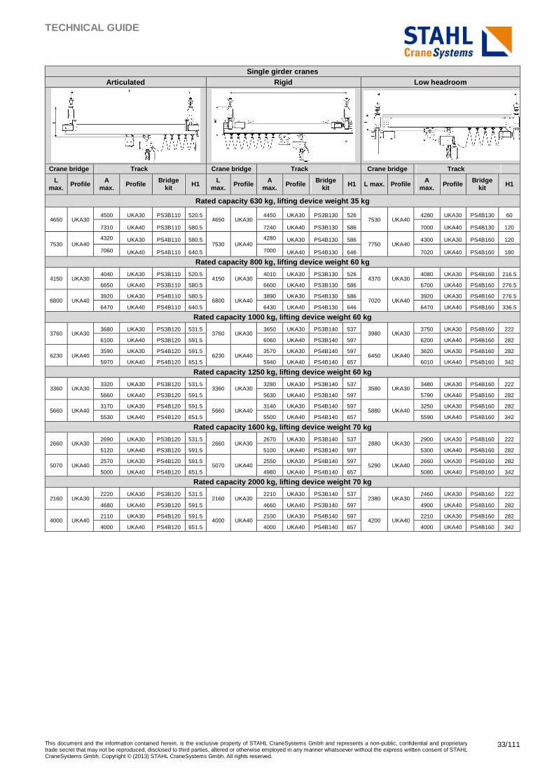
Single girder cranes Articulated Rigid Low headroom
Crane bridge Track Crane bridge Track Crane bridge Track
L max. Profile A
max. Profile Bridge kit H1 L
max. Profile A max. Profile Bridge
kit H1 L max. Profile A max. Profile Bridge
kit H1
Rated capacity 630 kg, lifting device weight 35 kg
4650 UKA30 4500 UKA30 PS3B110 520.5
4650 UKA30 4450 UKA30 PS3B130 526
7530 UKA40 4280 UKA30 PS4B130 60
7310 UKA40 PS3B110 580.5 7240 UKA40 PS3B130 586 7000 UKA40 PS4B130 120
7530 UKA40 4320 UKA30 PS4B110 580.5
7530 UKA40 4280 UKA30 PS4B130 586
7750 UKA40 4300 UKA30 PS4B160 120
7060 UKA40 PS4B110 640.5 7000 UKA40 PS4B130 646 7020 UKA40 PS4B160 180
Rated capacity 800 kg, lifting device weight 60 kg
4150 UKA30 4040 UKA30 PS3B110 520.5
4150 UKA30 4010 UKA30 PS3B130 526
4370 UKA30 4080 UKA30 PS4B160 216.5
6650 UKA40 PS3B110 580.5 6600 UKA40 PS3B130 586 6700 UKA40 PS4B160 276.5
6800 UKA40 3920 UKA30 PS4B110 580.5
6800 UKA40 3890 UKA30 PS4B130 586
7020 UKA40 3920 UKA30 PS4B160 276.5
6470 UKA40 PS4B110 640.5 6430 UKA40 PS4B130 646 6470 UKA40 PS4B160 336.5
Rated capacity 1000 kg, lifting device weight 60 kg
3760 UKA30 3680 UKA30 PS3B120 531.5
3760 UKA30 3650 UKA30 PS3B140 537
3980 UKA30 3750 UKA30 PS4B160 222
6100 UKA40 PS3B120 591.5 6060 UKA40 PS3B140 597 6200 UKA40 PS4B160 282
6230 UKA40 3590 UKA30 PS4B120 591.5
6230 UKA40 3570 UKA30 PS4B140 597
6450 UKA40 3620 UKA30 PS4B160 282
5970 UKA40 PS4B120 651.5 5940 UKA40 PS4B140 657 6010 UKA40 PS4B160 342
Rated capacity 1250 kg, lifting device weight 60 kg
3360 UKA30 3320 UKA30 PS3B120 531.5
3360 UKA30 3280 UKA30 PS3B140 537
3580 UKA30 3480 UKA30 PS4B160 222
5660 UKA40 PS3B120 591.5 5630 UKA40 PS3B140 597 5790 UKA40 PS4B160 282
5660 UKA40 3170 UKA30 PS4B120 591.5
5660 UKA40 3140 UKA30 PS4B140 597
5880 UKA40 3250 UKA30 PS4B160 282
5530 UKA40 PS4B120 651.5 5500 UKA40 PS4B140 657 5590 UKA40 PS4B160 342
Rated capacity 1600 kg, lifting device weight 70 kg
2660 UKA30 2690 UKA30 PS3B120 531.5
2660 UKA30 2670 UKA30 PS3B140 537
2880 UKA30 2900 UKA30 PS4B160 222
5120 UKA40 PS3B120 591.5 5100 UKA40 PS3B140 597 5300 UKA40 PS4B160 282
5070 UKA40 2570 UKA30 PS4B120 591.5
5070 UKA40 2550 UKA30 PS4B140 597
5290 UKA40 2660 UKA30 PS4B160 282
5000 UKA40 PS4B120 651.5 4980 UKA40 PS4B140 657 5080 UKA40 PS4B160 342
Rated capacity 2000 kg, lifting device weight 70 kg
2160 UKA30 2220 UKA30 PS3B120 531.5
2160 UKA30 2210 UKA30 PS3B140 537
2380 UKA30 2460 UKA30 PS4B160 222
4680 UKA40 PS3B120 591.5 4660 UKA40 PS3B140 597 4900 UKA40 PS4B160 282
4000 UKA40 2110 UKA30 PS4B120 591.5
4000 UKA40 2100 UKA30 PS4B140 597
4200 UKA40 2210 UKA30 PS4B160 282
4000 UKA40 PS4B120 651.5 4000 UKA40 PS4B140 657 4000 UKA40 PS4B160 342
TECHNICAL GUIDE
This document and the information contained herein, is the exclusive property of STAHL CraneSystems Gmbh and represents a non-public, confidential and proprietary trade secret that may not be reproduced, disclosed to third parties, altered or otherwise employed in any manner whatsoever without the express written consent of STAHL CraneSystems Gmbh. Copyright © (2013) STAHL CraneSystems Gmbh. All rights reserved.
34/111
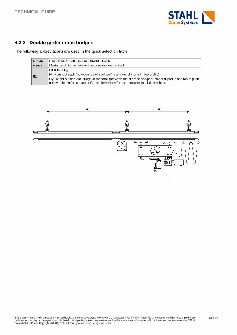
4.2.2 Double girder crane bridges
The following abbreviations are used in the quick selection table:
L max. (=span) Maximum distance between tracks
A max. Maximum distance between suspensions on the track
H1
H1 = HT + HB HT: Height of track (between top of track profile and top of crane bridge profile) HB: Height of the crane bridge or monorail (between top of crane bridge or monorail profile and top of push trolley bolt). Refer to chapter Crane dimensions for the complete list of dimensions.
TECHNICAL GUIDE
This document and the information contained herein, is the exclusive property of STAHL CraneSystems Gmbh and represents a non-public, confidential and proprietary trade secret that may not be reproduced, disclosed to third parties, altered or otherwise employed in any manner whatsoever without the express written consent of STAHL CraneSystems Gmbh. Copyright © (2013) STAHL CraneSystems Gmbh. All rights reserved.
35/111
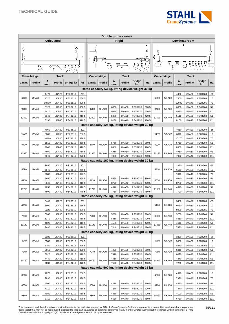
Double girder cranes
Articulated Rigid Low headroom
Crane bridge Track Crane bridge Track Crane bridge Track
L max. Profile A max. Profile Bridge kit H1 L max. Profile A
max. Profile Bridge kit H1 L max. Profile A
max. Profile Bridge kit H1
Rated capacity 63 kg, lifting device weight 30 kg
6630 UKA20
4470 UKA20 PS2B510 201
6850 UKA20
4450 UKA20 PS2B260 -55
7320 UKA30 PS2B515 266.5 7300 UKA30 PS2B265 10
10700 UKA40 PS2B515 326.5 10680 UKA40 PS2B265 70
9260 UKA30 6120 UKA30 PS3B210 358.5
9260 UKA30 6050 UKA30 PS3B230 360.5
9480 UKA30 6050 UKA30 PS4B260 51
9410 UKA40 PS3B210 418.5 9320 UKA40 PS3B230 420.5 9330 UKA40 PS4B260 111
12400 UKA40 5140 UKA30 PS4B210 418.5
12400 UKA40 5090 UKA30 PS4B230 420.5
12620 UKA40 5110 UKA30 PS4B260 51
8190 UKA40 PS4B210 478.5 8130 UKA40 PS4B230 480.5 8160 UKA40 PS4B260 111
Rated capacity 125 kg, lifting device weight 30 kg
5920 UKA20
4050 UKA20 PS2B510 201
6140 UKA20
4050 UKA20 PS2B260 -55
6800 UKA30 PS2B515 266.5 6810 UKA30 PS2B265 10
10160 UKA40 PS2B515 326.5 10170 UKA40 PS2B265 70
8700 UKA30 5810 UKA30 PS3B210 358.5
8700 UKA30 5750 UKA30 PS3B230 360.5
8920 UKA30 5760 UKA30 PS4B260 51
9040 UKA40 PS3B210 418.5 8960 UKA40 PS3B230 420.5 8980 UKA40 PS4B260 111
11950 UKA40 4950 UKA30 PS4B210 418.5
11950 UKA40 4910 UKA30 PS4B230 420.5
12170 UKA40 4930 UKA30 PS4B260 51
7940 UKA40 PS4B210 478.5 7880 UKA40 PS4B230 480.5 7920 UKA40 PS4B260 111
Rated capacity 160 kg, lifting device weight 30 kg
5590 UKA20
3850 UKA20 PS2B510 201
5810 UKA20
3870 UKA20 PS2B260 -55
6540 UKA30 PS2B515 266.5 6560 UKA30 PS2B265 10
9880 UKA40 PS2B515 326.5 9910 UKA40 PS2B265 70
8410 UKA30 5650 UKA30 PS3B210 358.5
8410 UKA30 5590 UKA30 PS3B230 360.5
8630 UKA30 5610 UKA30 PS4B260 51
8840 UKA40 PS3B210 418.5 8770 UKA40 PS3B230 420.5 8790 UKA40 PS4B260 111
11710 UKA40 4850 UKA30 PS4B210 418.5
11710 UKA40 4820 UKA30 PS4B230 420.5
11930 UKA40 4840 UKA30 PS4B260 51
7800 UKA40 PS4B210 478.5 7750 UKA40 PS4B230 480.5 7790 UKA40 PS4B260 111
Rated capacity 250 kg, lifting device weight 30 kg
4950 UKA20
3440 UKA20 PS2B510 201
5170 UKA20
3480 UKA20 PS2B260 -55
5960 UKA30 PS2B515 266.5 6020 UKA30 PS2B265 10
9220 UKA40 PS2B515 326.5 9290 UKA40 PS2B265 70
7780 UKA30 5280 UKA30 PS3B210 358.5
7780 UKA30 5230 UKA30 PS3B230 360.5
8000 UKA30 5260 UKA30 PS4B260 51
8370 UKA40 PS3B210 418.5 8310 UKA40 PS3B230 420.5 8350 UKA40 PS4B260 111
11140 UKA40 4620 UKA30 PS4B210 418.5
11140 UKA40 4590 UKA30 PS4B230 420.5
11360 UKA40 4610 UKA30 PS4B260 51
7480 UKA40 PS4B210 478.5 7440 UKA40 PS4B230 480.5 7470 UKA40 PS4B260 111
Rated capacity 320 kg, lifting device weight 35 kg
4540 UKA20
3180 UKA20 PS2B510 201
4760 UKA20
3230 UKA20 PS2B260 -55
5580 UKA30 PS2B515 266.5 5650 UKA30 PS2B265 10
8750 UKA40 PS2B515 326.5 8840 UKA40 PS2B265 70
7340 UKA30 5010 UKA30 PS3B210 358.5
7340 UKA30 4970 UKA30 PS3B230 360.5
7560 UKA30 5010 UKA30 PS4B260 51
8020 UKA40 PS3B210 418.5 7970 UKA40 PS3B230 420.5 8020 UKA40 PS4B260 111
10720 UKA40 4440 UKA30 PS4B210 418.5
10720 UKA40 4410 UKA30 PS4B230 420.5
10940 UKA40 4440 UKA30 PS4B260 51
7230 UKA40 PS4B210 478.5 7190 UKA40 PS4B230 480.5 7230 UKA40 PS4B260 111
Rated capacity 500 kg, lifting device weight 35 kg
3860 UKA20 4870 UKA30 PS2B515 266.5
4080 UKA20 4970 UKA30 PS2B265 10
7830 UKA40 PS2B515 326.5 7970 UKA40 PS2B265 70
6500 UKA30 4500 UKA30 PS3B210 358.5
6500 UKA30 4470 UKA30 PS3B230 360.5
6720 UKA30 4520 UKA30 PS4B260 51
7310 UKA40 PS3B210 418.5 7270 UKA40 PS3B230 420.5 7340 UKA40 PS4B260 111
9840 UKA40 4080 UKA30 PS4B210 418.5
9840 UKA40 4060 UKA30 PS4B230 420.5
10060 UKA40 4100 UKA30 PS4B260 51
6710 UKA40 PS4B210 478.5 6680 UKA40 PS4B230 480.5 6730 UKA40 PS4B260 111
TECHNICAL GUIDE
This document and the information contained herein, is the exclusive property of STAHL CraneSystems Gmbh and represents a non-public, confidential and proprietary trade secret that may not be reproduced, disclosed to third parties, altered or otherwise employed in any manner whatsoever without the express written consent of STAHL CraneSystems Gmbh. Copyright © (2013) STAHL CraneSystems Gmbh. All rights reserved.
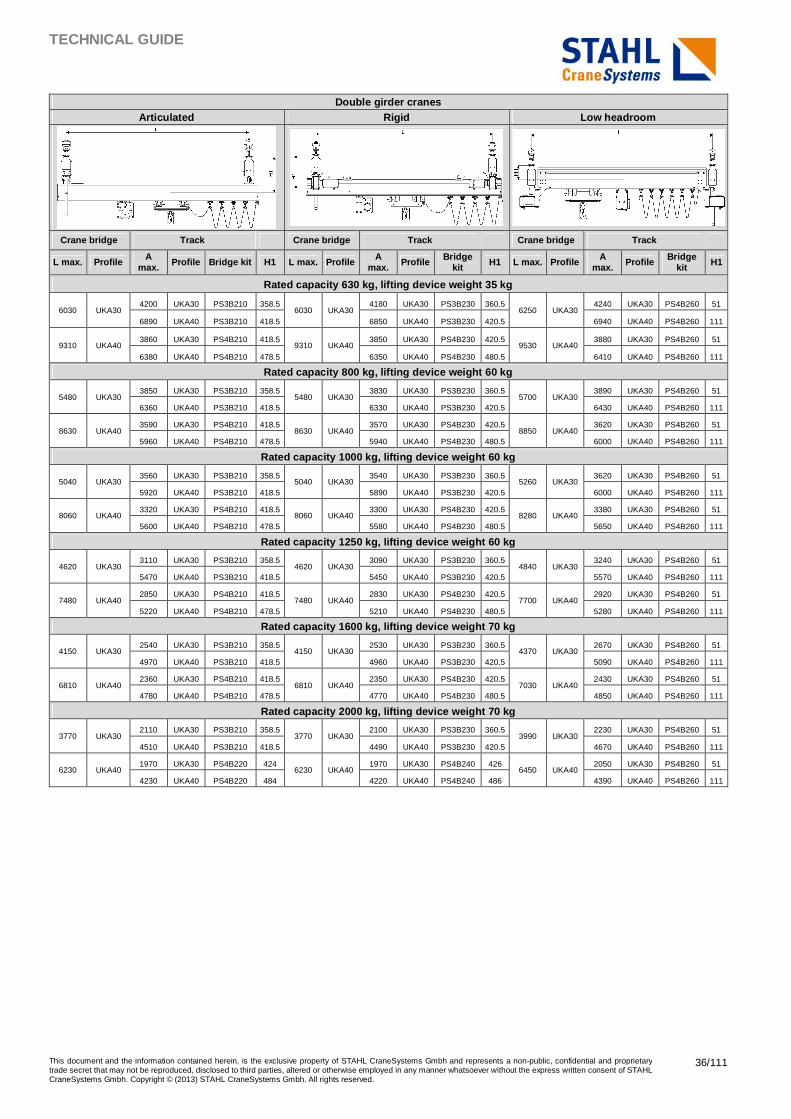
36/111
Double girder cranes Articulated Rigid Low headroom
Crane bridge Track Crane bridge Track Crane bridge Track
L max. Profile A max. Profile Bridge kit H1 L max. Profile A
max. Profile Bridge kit H1 L max. Profile A
max. Profile Bridge kit H1
Rated capacity 630 kg, lifting device weight 35 kg
6030 UKA30 4200 UKA30 PS3B210 358.5
6030 UKA30 4180 UKA30 PS3B230 360.5
6250 UKA30 4240 UKA30 PS4B260 51
6890 UKA40 PS3B210 418.5 6850 UKA40 PS3B230 420.5 6940 UKA40 PS4B260 111
9310 UKA40 3860 UKA30 PS4B210 418.5
9310 UKA40 3850 UKA30 PS4B230 420.5
9530 UKA40 3880 UKA30 PS4B260 51
6380 UKA40 PS4B210 478.5 6350 UKA40 PS4B230 480.5 6410 UKA40 PS4B260 111
Rated capacity 800 kg, lifting device weight 60 kg
5480 UKA30 3850 UKA30 PS3B210 358.5
5480 UKA30 3830 UKA30 PS3B230 360.5
5700 UKA30 3890 UKA30 PS4B260 51
6360 UKA40 PS3B210 418.5 6330 UKA40 PS3B230 420.5 6430 UKA40 PS4B260 111
8630 UKA40 3590 UKA30 PS4B210 418.5
8630 UKA40 3570 UKA30 PS4B230 420.5
8850 UKA40 3620 UKA30 PS4B260 51
5960 UKA40 PS4B210 478.5 5940 UKA40 PS4B230 480.5 6000 UKA40 PS4B260 111
Rated capacity 1000 kg, lifting device weight 60 kg
5040 UKA30 3560 UKA30 PS3B210 358.5
5040 UKA30 3540 UKA30 PS3B230 360.5
5260 UKA30 3620 UKA30 PS4B260 51
5920 UKA40 PS3B210 418.5 5890 UKA40 PS3B230 420.5 6000 UKA40 PS4B260 111
8060 UKA40 3320 UKA30 PS4B210 418.5
8060 UKA40 3300 UKA30 PS4B230 420.5
8280 UKA40 3380 UKA30 PS4B260 51
5600 UKA40 PS4B210 478.5 5580 UKA40 PS4B230 480.5 5650 UKA40 PS4B260 111
Rated capacity 1250 kg, lifting device weight 60 kg
4620 UKA30 3110 UKA30 PS3B210 358.5
4620 UKA30 3090 UKA30 PS3B230 360.5
4840 UKA30 3240 UKA30 PS4B260 51
5470 UKA40 PS3B210 418.5 5450 UKA40 PS3B230 420.5 5570 UKA40 PS4B260 111
7480 UKA40 2850 UKA30 PS4B210 418.5
7480 UKA40 2830 UKA30 PS4B230 420.5
7700 UKA40 2920 UKA30 PS4B260 51
5220 UKA40 PS4B210 478.5 5210 UKA40 PS4B230 480.5 5280 UKA40 PS4B260 111
Rated capacity 1600 kg, lifting device weight 70 kg
4150 UKA30 2540 UKA30 PS3B210 358.5
4150 UKA30 2530 UKA30 PS3B230 360.5
4370 UKA30 2670 UKA30 PS4B260 51
4970 UKA40 PS3B210 418.5 4960 UKA40 PS3B230 420.5 5090 UKA40 PS4B260 111
6810 UKA40 2360 UKA30 PS4B210 418.5
6810 UKA40 2350 UKA30 PS4B230 420.5
7030 UKA40 2430 UKA30 PS4B260 51
4780 UKA40 PS4B210 478.5 4770 UKA40 PS4B230 480.5 4850 UKA40 PS4B260 111
Rated capacity 2000 kg, lifting device weight 70 kg
3770 UKA30 2110 UKA30 PS3B210 358.5
3770 UKA30 2100 UKA30 PS3B230 360.5
3990 UKA30 2230 UKA30 PS4B260 51
4510 UKA40 PS3B210 418.5 4490 UKA40 PS3B230 420.5 4670 UKA40 PS4B260 111
6230 UKA40 1970 UKA30 PS4B220 424
6230 UKA40 1970 UKA30 PS4B240 426
6450 UKA40 2050 UKA30 PS4B260 51
4230 UKA40 PS4B220 484 4220 UKA40 PS4B240 486 4390 UKA40 PS4B260 111
TECHNICAL GUIDE
This document and the information contained herein, is the exclusive property of STAHL CraneSystems Gmbh and represents a non-public, confidential and proprietary trade secret that may not be reproduced, disclosed to third parties, altered or otherwise employed in any manner whatsoever without the express written consent of STAHL CraneSystems Gmbh. Copyright © (2013) STAHL CraneSystems Gmbh. All rights reserved.
37/111
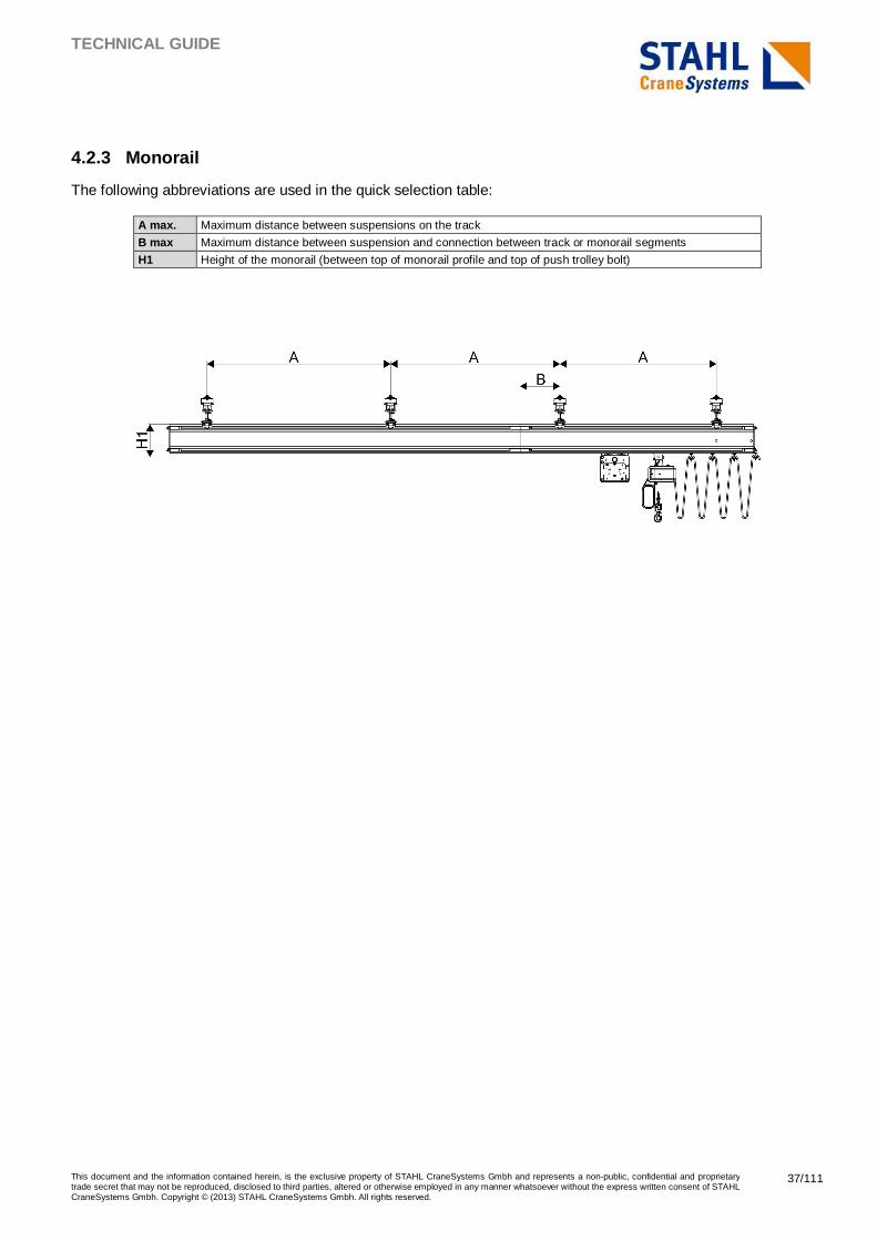
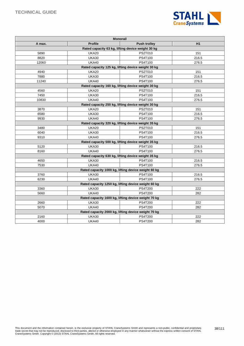
4.2.3 Monorail
The following abbreviations are used in the quick selection table:
A max. Maximum distance between suspensions on the track
B max Maximum distance between suspension and connection between track or monorail segments
H1 Height of the monorail (between top of monorail profile and top of push trolley bolt)
TECHNICAL GUIDE
This document and the information contained herein, is the exclusive property of STAHL CraneSystems Gmbh and represents a non-public, confidential and proprietary trade secret that may not be reproduced, disclosed to third parties, altered or otherwise employed in any manner whatsoever without the express written consent of STAHL CraneSystems Gmbh. Copyright © (2013) STAHL CraneSystems Gmbh. All rights reserved.
38/111
Monorail A max. Profile Push trolley H1
Rated capacity 63 kg, lifting device weight 30 kg 5890 UKA20 PS2T010 151
8820 UKA30 PS4T100 216.5 12060 UKA40 PS4T100 276.5
Rated capacity 125 kg, lifting device weight 30 kg 4940 UKA20 PS2T010 151
7880 UKA30 PS4T100 216.5 11240 UKA40 PS4T100 276.5
Rated capacity 160 kg, lifting device weight 30 kg 4560 UKA20 PS2T010 151 7450 UKA30 PS4T100 216.5 10830 UKA40 PS4T100 276.5
Rated capacity 250 kg, lifting device weight 30 kg 3870 UKA20 PS2T010 151 6580 UKA30 PS4T100 216.5 9930 UKA40 PS4T100 276.5
Rated capacity 320 kg, lifting device weight 35 kg 3480 UKA20 PS2T010 151 6040 UKA30 PS4T100 216.5
9310 UKA40 PS4T100 276.5 Rated capacity 500 kg, lifting device weight 35 kg
5120 UKA30 PS4T100 216.5 8160 UKA40 PS4T100 276.5
Rated capacity 630 kg, lifting device weight 35 kg 4650 UKA30 PS4T100 216.5 7530 UKA40 PS4T100 276.5
Rated capacity 1000 kg, lifting device weight 60 kg 3760 UKA30 PS4T100 216.5 6230 UKA40 PS4T100 276.5
Rated capacity 1250 kg, lifting device weight 60 kg 3360 UKA30 PS4T200 222 5660 UKA40 PS4T200 282
Rated capacity 1600 kg, lifting device weight 70 kg 2660 UKA30 PS4T200 222 5070 UKA40 PS4T200 282
Rated capacity 2000 kg, lifting device weight 70 kg 2160 UKA30 PS4T200 222 4000 UKA40 PS4T200 282
TECHNICAL GUIDE
This document and the information contained herein, is the exclusive property of STAHL CraneSystems Gmbh and represents a non-public, confidential and proprietary trade secret that may not be reproduced, disclosed to third parties, altered or otherwise employed in any manner whatsoever without the express written consent of STAHL CraneSystems Gmbh. Copyright © (2013) STAHL CraneSystems Gmbh. All rights reserved.
39/111
4.3 Detailed calculation
4.3.1 Data required for calculation
The selection of a proper crane system requires knowledge of the crane operation environment, limits of the components, geometry of the crane, type of load (including the dynamic factor), and the product weights.
To determine the suitable product and profiles, the product weights must be calculated. The calculations are explained in the following sections and summarized in the following table.
Rails
Product Description Suitability Weight [kg/m] UKA20 Rail Crane bridge and track 10
UKA30 Rail Crane bridge and track 19.1
UKA40 Rail Crane bridge and track 28.9
Trolleys
Product Description Suitability
Weight [kg] Trolley type Max. [kg] Track rail Crane type
PS2T010 Push trolley, single 400 UKA20 Single girder crane bridges and monorails 2.3
PS4T100 Push trolley, single 1100 UKA30, UKA40 Single girder crane bridges and monorails 3.1
PS4T200 Push trolley, double 2200 UKA30, UKA40 Single girder crane bridges and monorails 12.2
PS4T400 Swiveling push trolley, double
2200 UKA30, UKA40 Circuit with curves or switches 15.2
PS2T500 Push trolley 500 UKA20 Double girder crane bridges 33.0
PS4T500 Push trolley 2500 UKA30, UKA40 Double girder crane bridges 52.0
UKTM Motor trolley - UKA30, UKA40 Cranes, monorails, circuits 42.0
UKTM2 Motor trolley - UKA30, UKA40 Cranes and straight monorails 24.0
Lifting devices and bridge kits
Product Description Lifting devices Refer to the lifting device technical documentation Bridge kit See chapter Crane dimensions
Note : The results of the detailed calculation must be evaluated with the sales configurator.
TECHNICAL GUIDE
This document and the information contained herein, is the exclusive property of STAHL CraneSystems Gmbh and represents a non-public, confidential and proprietary trade secret that may not be reproduced, disclosed to third parties, altered or otherwise employed in any manner whatsoever without the express written consent of STAHL CraneSystems Gmbh. Copyright © (2013) STAHL CraneSystems Gmbh. All rights reserved.
40/111
4.3.2 Calculating load spectrum and determining rat ed capacity
All the tables in this chapter are given for a load spectrum of kp = 1, spectrum class Q4, and utilization class U2 (maximum number of hoisting cycles = 63000 at full capacity).
When a higher number of cycles is required, the rated capacity must be increased compared to the real load. Increasing the capacity is done to decrease the load spectrum, and in that way to stay in the A4 application class.
The load spectrum is calculated as follows:
Abbreviations ml Real lifted loads n Number of hoisting cycles when the hoisted load is equal to ml nmax Number of hoisting cycles determining the total duration of use
RC Rated capacity
4.3.3 Determining rail type
The following graphs show the maximal crane spans and loadings in respect of two criteria: the maximum deflection and the maximum stress in the rail. The loading is not the same as the rated capacity. The weight of the lifting device and the motor trolley, as well as any possible extra weight – such as the weight of the power feeding lines and the handling equipment – have to be added to the lifted load. The loading calculations differ for the two following criteria:
� Maximum deflection criteria that considers the static load, and is aimed to prevent the self-movement of the lifted load.
� Maximum stress criteria that considers the dynamic factor given by the hoisting movement and that is aimed to prevent the fatigue of the rail.
These curves can be used for the crane bridge span and the maximum distance between the track suspensions for crane systems with one single crane bridge. In this case, the crane bridge dead weight must be added.
Other limits that can reduce the maximum span are, among others, the outreach, the length of the segment (only one connection is allowed on girders), and the loading of the suspensions.
Note : In addition to the maximum span, the following points must be checked:
• Maximum outreach
• Trolley and suspension capacities
• Connection positions on the track.
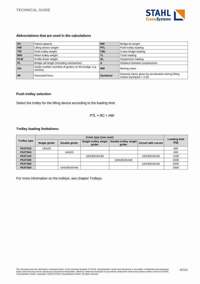
TECHNICAL GUIDE
This document and the information contained herein, is the exclusive property of STAHL CraneSystems Gmbh and represents a non-public, confidential and proprietary trade secret that may not be reproduced, disclosed to third parties, altered or otherwise employed in any manner whatsoever without the express written consent of STAHL CraneSystems Gmbh. Copyright © (2013) STAHL CraneSystems Gmbh. All rights reserved.
41/111
Abbreviations that are used in the calculations
RC Rated capacity BW Bridge kit weight HW Lifting device weight PTL Push trolley loading
TW Push trolley weight CBL Crane bridge loading MW Motor trolley weight TL Track loading PLW Profile linear weight SL Suspension loading
PL Bridge rail length (including outreaches) A Distance between suspensions
GN Girder number (number of girders on the bridge, e.g. SG/DG) MM Moving mass
HF Horizontal force Dynfactor Dynamic factor given by acceleration during lifting motion Dynfactor = 0.25
Push trolley selection
Select the trolley for the lifting device according to the loading limit:
Trolley loading limitations:
Trolley type Crane type (use case)
Loading limit [kg] Single girder Double girder Single trolley single
girder Double trolley single
girder Circuit with curves
PS2T010 UKA20 400 PS2T500 UKA20 600 PS4T100 UKA30/UKA40 UKA30/UKA40 1100
PS4T200 UKA30/UKA40 2200 PS4T400 UKA30/UKA40 2200 PS4T500 UKA30/UKA40 2500
For more information on the trolleys, see chapter Trolleys.
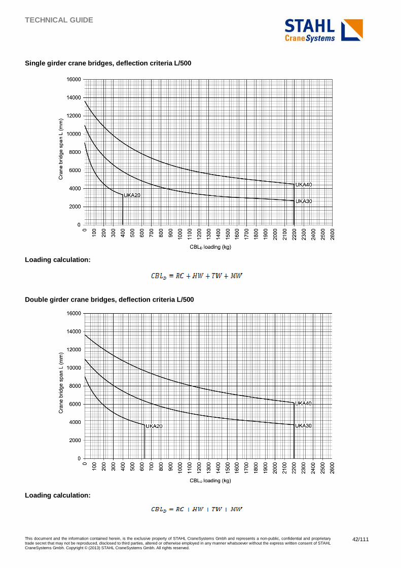
TECHNICAL GUIDE
This document and the information contained herein, is the exclusive property of STAHL CraneSystems Gmbh and represents a non-public, confidential and proprietary trade secret that may not be reproduced, disclosed to third parties, altered or otherwise employed in any manner whatsoever without the express written consent of STAHL CraneSystems Gmbh. Copyright © (2013) STAHL CraneSystems Gmbh. All rights reserved.
42/111
Single girder crane bridges, deflection criteria L/ 500
Loading calculation:
Double girder crane bridges, deflection criteria L/ 500
Loading calculation:
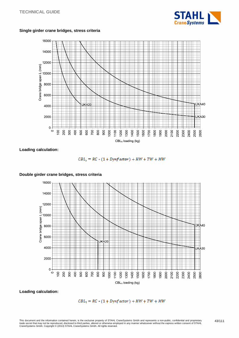
TECHNICAL GUIDE
This document and the information contained herein, is the exclusive property of STAHL CraneSystems Gmbh and represents a non-public, confidential and proprietary trade secret that may not be reproduced, disclosed to third parties, altered or otherwise employed in any manner whatsoever without the express written consent of STAHL CraneSystems Gmbh. Copyright © (2013) STAHL CraneSystems Gmbh. All rights reserved.
43/111
Single girder crane bridges, stress criteria
Loading calculation:
Double girder crane bridges, stress criteria
Loading calculation:
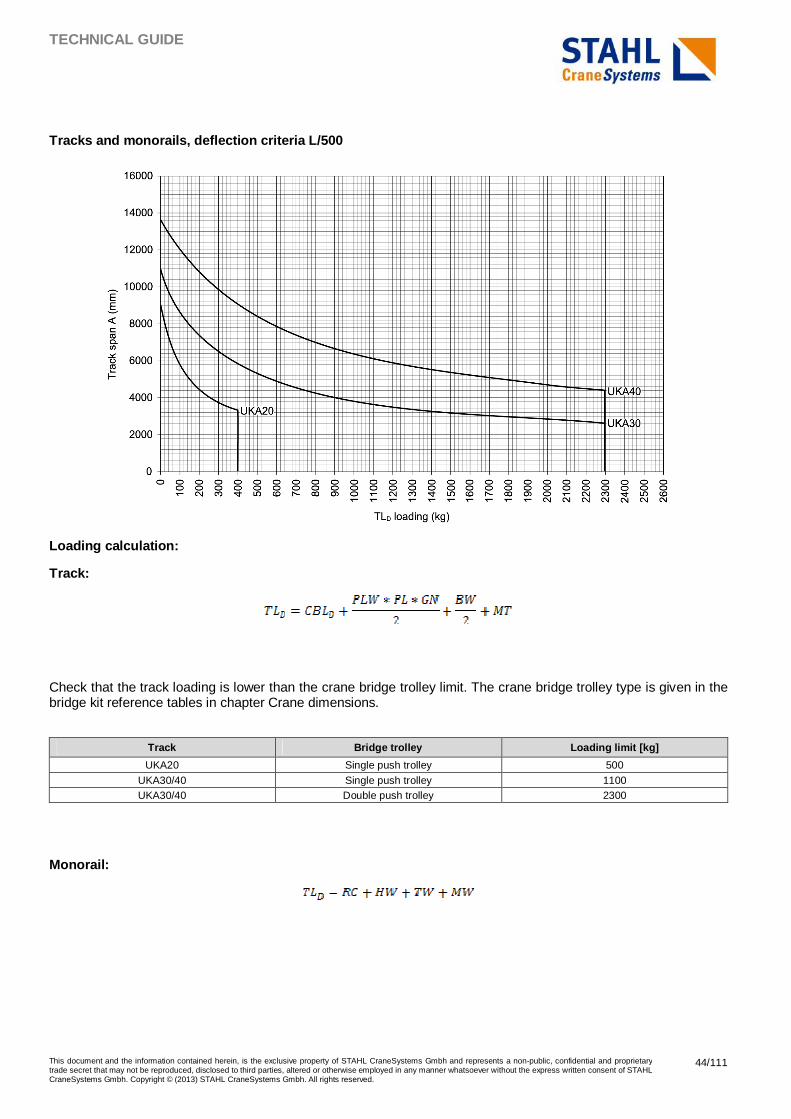
TECHNICAL GUIDE
This document and the information contained herein, is the exclusive property of STAHL CraneSystems Gmbh and represents a non-public, confidential and proprietary trade secret that may not be reproduced, disclosed to third parties, altered or otherwise employed in any manner whatsoever without the express written consent of STAHL CraneSystems Gmbh. Copyright © (2013) STAHL CraneSystems Gmbh. All rights reserved.
44/111
Tracks and monorails, deflection criteria L/500
Loading calculation:
Track:
Check that the track loading is lower than the crane bridge trolley limit. The crane bridge trolley type is given in the bridge kit reference tables in chapter Crane dimensions.
Track Bridge trolley Loading limit [kg]
UKA20 Single push trolley 500
UKA30/40 Single push trolley 1100 UKA30/40 Double push trolley 2300
Monorail:
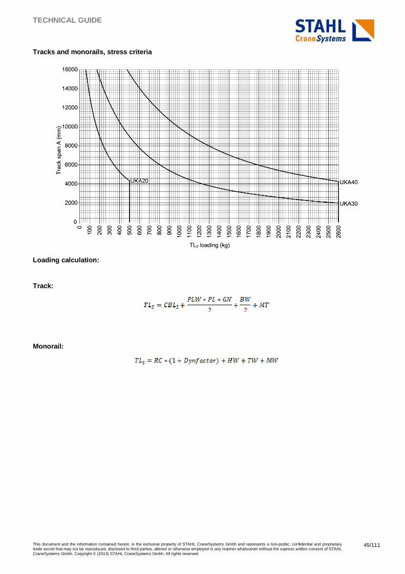
TECHNICAL GUIDE
This document and the information contained herein, is the exclusive property of STAHL CraneSystems Gmbh and represents a non-public, confidential and proprietary trade secret that may not be reproduced, disclosed to third parties, altered or otherwise employed in any manner whatsoever without the express written consent of STAHL CraneSystems Gmbh. Copyright © (2013) STAHL CraneSystems Gmbh. All rights reserved.
45/111
Tracks and monorails, stress criteria
Loading calculation:
Track:
Monorail:
TECHNICAL GUIDE
This document and the information contained herein, is the exclusive property of STAHL CraneSystems Gmbh and represents a non-public, confidential and proprietary trade secret that may not be reproduced, disclosed to third parties, altered or otherwise employed in any manner whatsoever without the express written consent of STAHL CraneSystems Gmbh. Copyright © (2013) STAHL CraneSystems Gmbh. All rights reserved.
46/111
4.3.4 Suspension limits and forces back to supporti ng structure
The suspension loading is calculated as follows:
The suspension loading is limited to 3000 kg.
The vertical force back to the supporting structure to be considered for checking is calculated without the dynamic factor:
The horizontal force back to the supporting structure to be considered for checking is 10% of the moving mass:
4.3.5 Examples of calculations*
Load spectrum calculation
A crane is used to load a machine. The rated capacity of the crane is 500 kg. The lifting equipment is fitted with a lifting beam which weighs 120 kg. The parts weigh 300 kg, and are lifted from the floor and lifted on the machine on which they are lowered. After removing the part, the lifting beam is lifted and lowered to get the next part.
There are two hoisting cycles per production cycle (one with the load + one with the lifting beam only).
Spectrum factor calculation:
The spectrum class is Q3. The maximum number of hoisting cycles to respect the utilization group A4 is 125000 as per utilization class U3.
*NOTE: All the calculations are done using the SI units ‘kg’ and ‘mm’.
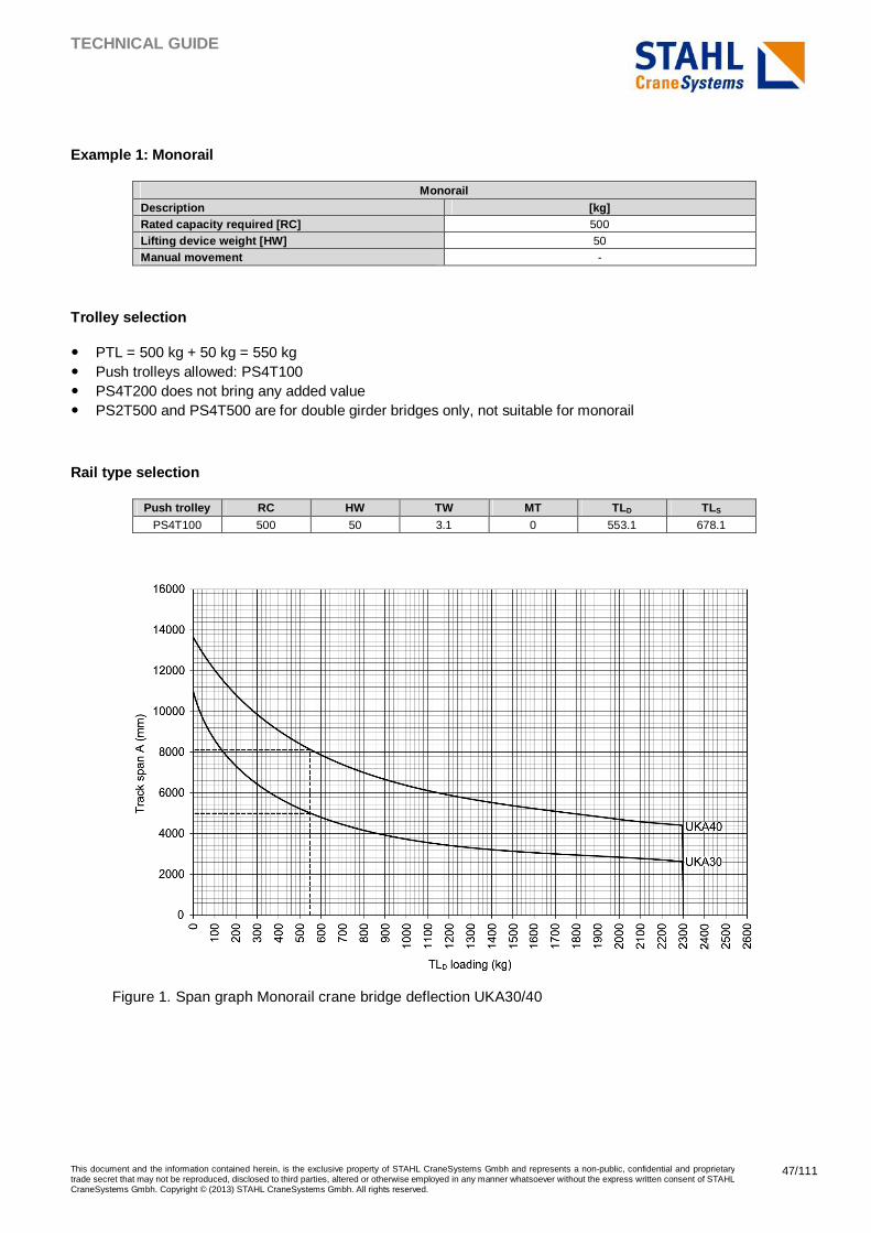
TECHNICAL GUIDE
This document and the information contained herein, is the exclusive property of STAHL CraneSystems Gmbh and represents a non-public, confidential and proprietary trade secret that may not be reproduced, disclosed to third parties, altered or otherwise employed in any manner whatsoever without the express written consent of STAHL CraneSystems Gmbh. Copyright © (2013) STAHL CraneSystems Gmbh. All rights reserved.
47/111
Example 1: Monorail
Monorail Description [kg] Rated capacity required [RC] 500 Lifting device weight [HW] 50 Manual movement -
Trolley selection
� PTL = 500 kg + 50 kg = 550 kg � Push trolleys allowed: PS4T100 � PS4T200 does not bring any added value � PS2T500 and PS4T500 are for double girder bridges only, not suitable for monorail
Rail type selection
Push trolley RC HW TW MT TLD TLS PS4T100 500 50 3.1 0 553.1 678.1
Figure 1. Span graph Monorail crane bridge deflection UKA30/40
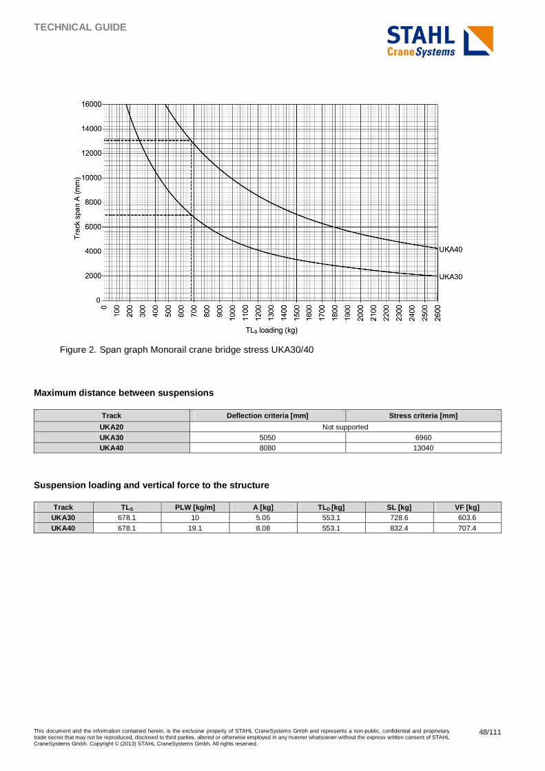
TECHNICAL GUIDE
This document and the information contained herein, is the exclusive property of STAHL CraneSystems Gmbh and represents a non-public, confidential and proprietary trade secret that may not be reproduced, disclosed to third parties, altered or otherwise employed in any manner whatsoever without the express written consent of STAHL CraneSystems Gmbh. Copyright © (2013) STAHL CraneSystems Gmbh. All rights reserved.
48/111
Figure 2. Span graph Monorail crane bridge stress UKA30/40
Maximum distance between suspensions
Track Deflection criteria [mm] Stress criteria [mm]
UKA20 Not supported
UKA30 5050 6960 UKA40 8080 13040
Suspension loading and vertical force to the struct ure
Track TLS PLW [kg/m] A [kg] TLD [kg] SL [kg] VF [kg] UKA30 678.1 10 5.05 553.1 728.6 603.6
UKA40 678.1 19.1 8.08 553.1 832.4 707.4
TECHNICAL GUIDE
This document and the information contained herein, is the exclusive property of STAHL CraneSystems Gmbh and represents a non-public, confidential and proprietary trade secret that may not be reproduced, disclosed to third parties, altered or otherwise employed in any manner whatsoever without the express written consent of STAHL CraneSystems Gmbh. Copyright © (2013) STAHL CraneSystems Gmbh. All rights reserved.
49/111
Example 2: Light crane system
Light crane system Description Unit or type Rated capacity required [RC] [kg] 453.6
Lifting device weight [HW] [kg] 45.4
Cross travel direction movement motorized
Long travel direction movement manual
Required span [L] [m] 5.48
Outreach [mm] 150
According to the requirements, an articulated crane bridge can be used in this example. To evaluate the most suitable crane bridge type, this example shows calculations with different alternatives.
Trolley selection
� PTL = 453.6 kg + 45.4 kg = 499 kg
� Push trolleys allowed: PS4T100 (single girder bridge), PS2T500, PS4T500 (double girder bridges)
� Push trolley PS4T200 is not required because PTL is lower than 1100 kg.
Rail type selection
First calculate the crane bridge loading:
Push trolley RC HW TW MT CBL D CBLS PS2T500 453.6 45.4 33 24 556 669.4 PS4T100 453.6 45.4 3.1 24 526.1 639.5
PS4T500 453.6 45.4 52 24 575 688.4
*NOTE: The values here for the PS2T500 and the PS4T500 push trolleys are for double girder cranes. The PS4T100 values are for a single girder crane.
Maximum span allowed
Use the CBL values in the single or double girder graphs to check the maximum span L.
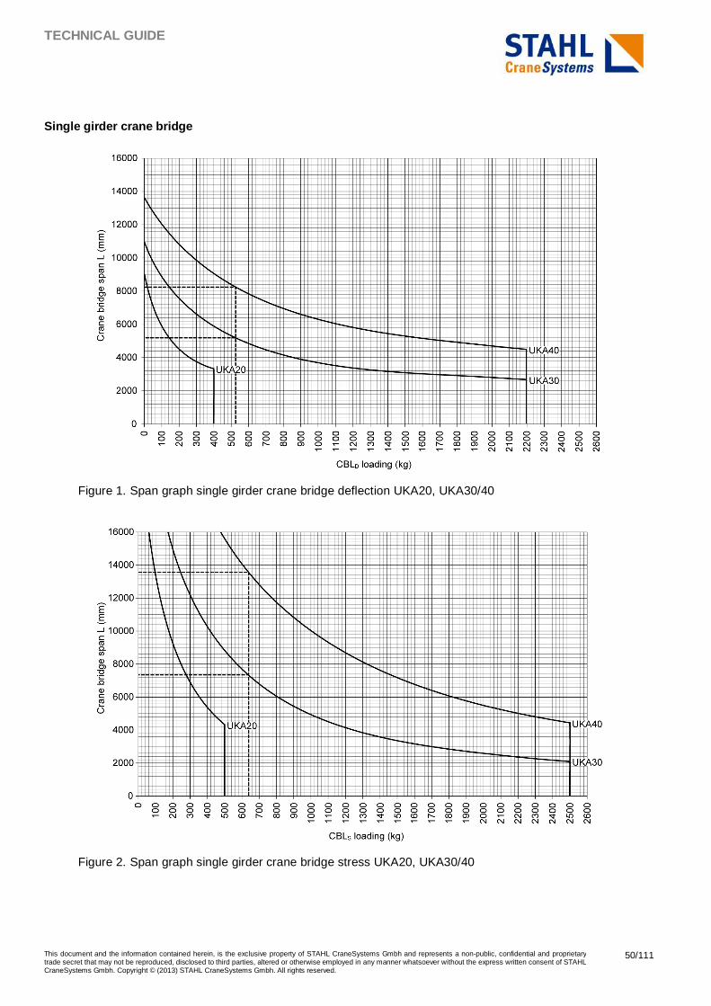
TECHNICAL GUIDE
This document and the information contained herein, is the exclusive property of STAHL CraneSystems Gmbh and represents a non-public, confidential and proprietary trade secret that may not be reproduced, disclosed to third parties, altered or otherwise employed in any manner whatsoever without the express written consent of STAHL CraneSystems Gmbh. Copyright © (2013) STAHL CraneSystems Gmbh. All rights reserved.
50/111
Single girder crane bridge
Figure 1. Span graph single girder crane bridge deflection UKA20, UKA30/40
Figure 2. Span graph single girder crane bridge stress UKA20, UKA30/40
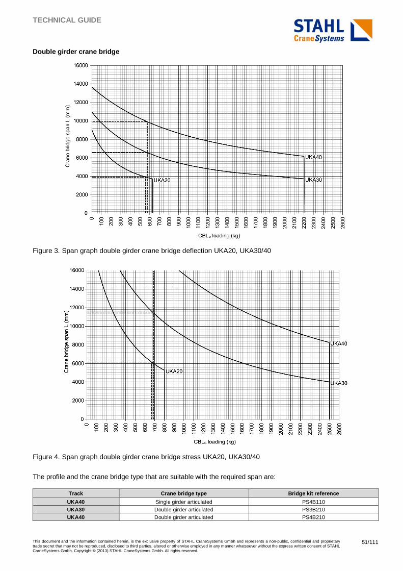
TECHNICAL GUIDE
This document and the information contained herein, is the exclusive property of STAHL CraneSystems Gmbh and represents a non-public, confidential and proprietary trade secret that may not be reproduced, disclosed to third parties, altered or otherwise employed in any manner whatsoever without the express written consent of STAHL CraneSystems Gmbh. Copyright © (2013) STAHL CraneSystems Gmbh. All rights reserved.
51/111
Double girder crane bridge
Figure 3. Span graph double girder crane bridge deflection UKA20, UKA30/40
Figure 4. Span graph double girder crane bridge stress UKA20, UKA30/40
The profile and the crane bridge type that are suitable with the required span are:
Track Crane bridge type Bridge kit reference
UKA40 Single girder articulated PS4B110 UKA30 Double girder articulated PS3B210 UKA40 Double girder articulated PS4B210
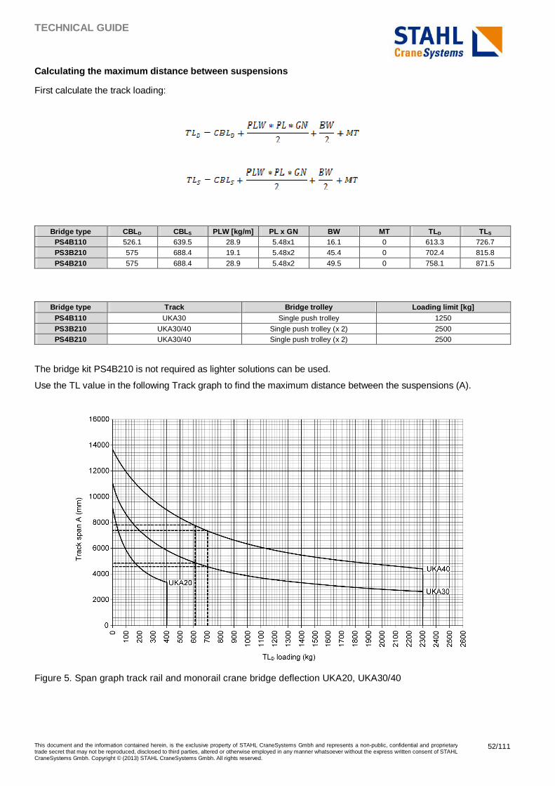
TECHNICAL GUIDE
This document and the information contained herein, is the exclusive property of STAHL CraneSystems Gmbh and represents a non-public, confidential and proprietary trade secret that may not be reproduced, disclosed to third parties, altered or otherwise employed in any manner whatsoever without the express written consent of STAHL CraneSystems Gmbh. Copyright © (2013) STAHL CraneSystems Gmbh. All rights reserved.
52/111
Calculating the maximum distance between suspension s
First calculate the track loading:
Bridge type CBL D CBLS PLW [kg/m] PL x GN BW MT TLD TLS
PS4B110 526.1 639.5 28.9 5.48x1 16.1 0 613.3 726.7 PS3B210 575 688.4 19.1 5.48x2 45.4 0 702.4 815.8
PS4B210 575 688.4 28.9 5.48x2 49.5 0 758.1 871.5
Bridge type Track Bridge trolley Loading limit [kg]
PS4B110 UKA30 Single push trolley 1250
PS3B210 UKA30/40 Single push trolley (x 2) 2500 PS4B210 UKA30/40 Single push trolley (x 2) 2500
The bridge kit PS4B210 is not required as lighter solutions can be used.
Use the TL value in the following Track graph to find the maximum distance between the suspensions (A).
Figure 5. Span graph track rail and monorail crane bridge deflection UKA20, UKA30/40
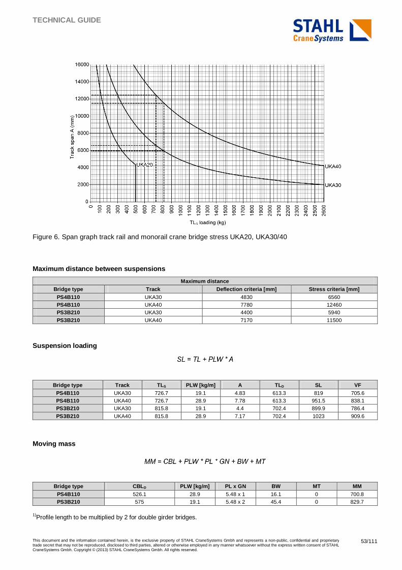
TECHNICAL GUIDE
This document and the information contained herein, is the exclusive property of STAHL CraneSystems Gmbh and represents a non-public, confidential and proprietary trade secret that may not be reproduced, disclosed to third parties, altered or otherwise employed in any manner whatsoever without the express written consent of STAHL CraneSystems Gmbh. Copyright © (2013) STAHL CraneSystems Gmbh. All rights reserved.
53/111
Figure 6. Span graph track rail and monorail crane bridge stress UKA20, UKA30/40
Maximum distance between suspensions
Maximum distance Bridge type Track Deflection criteria [mm] Stress criteria [mm]
PS4B110 UKA30 4830 6560 PS4B110 UKA40 7780 12460 PS3B210 UKA30 4400 5940
PS3B210 UKA40 7170 11500
Suspension loading
Bridge type Track TLS PLW [kg/m] A TLD SL VF PS4B110 UKA30 726.7 19.1 4.83 613.3 819 705.6 PS4B110 UKA40 726.7 28.9 7.78 613.3 951.5 838.1 PS3B210 UKA30 815.8 19.1 4.4 702.4 899.9 786.4
PS3B210 UKA40 815.8 28.9 7.17 702.4 1023 909.6
Moving mass
Bridge type CBL D PLW [kg/m] PL x GN BW MT MM PS4B110 526.1 28.9 5.48 x 1 16.1 0 700.8 PS3B210 575 19.1 5.48 x 2 45.4 0 829.7
1)Profile length to be multiplied by 2 for double girder bridges.
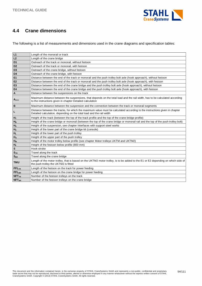
TECHNICAL GUIDE
This document and the information contained herein, is the exclusive property of STAHL CraneSystems Gmbh and represents a non-public, confidential and proprietary trade secret that may not be reproduced, disclosed to third parties, altered or otherwise employed in any manner whatsoever without the express written consent of STAHL CraneSystems Gmbh. Copyright © (2013) STAHL CraneSystems Gmbh. All rights reserved.
54/111
4.4 Crane dimensions
The following is a list of measurements and dimensions used in the crane diagrams and specification tables:
L1 Length of the monorail or track L2 Length of the crane bridge D1 Outreach of the track or monorail, without festoon
D2 Outreach of the track or monorail, with festoon D3 Outreach of the crane bridge, without festoon D4 Outreach of the crane bridge, with festoon E1 Distance between the end of the track or monorail and the push trolley bolt axle (hook approach), without festoon
E2 Distance between the end of the track or monorail and the push trolley bolt axle (hook approach), with festoon E3 Distance between the end of the crane bridge and the push trolley bolt axle (hook approach), without festoon E4 Distance between the end of the crane bridge and the push trolley bolt axle (hook approach), with festoon
A Distance between the suspensions on the track
AMAX Maximum distance between the suspensions, that depends on the total load and the rail width, has to be calculated according to the instructions given in chapter Detailed calculation
B Maximum distance between the suspension and the connection between the track or monorail segments
L Distance between the tracks, for which the maximum value must be calculated according to the instructions given in chapter Detailed calculation, depending on the total load and the rail width
HT Height of the track (between the top of the track profile and the top of the crane bridge profile) HB Height of the crane bridge or monorail (between the top of the crane bridge or monorail rail and the top of the push trolley bolt)
HS Height of the suspension, see chapter Interfaces with support steel works HC Height of the lower part of the crane bridge kit (console) HL Height of the lower part of the push trolley
HU Height of the upper part of the push trolley HM Height of the motor trolley below profile (see chapter Motor trolleys UKTM and UKTM2) HF Height of the festoon below profile (800 mm) S Hook stroke
STR Travel along the track SBR Travel along the crane bridge
TMU Length of the motor trolley, that is based on the UKTM2 motor trolley, is to be added to the E1 or E2 depending on which side of the push trolley the UKTM2 is fitted
PFLTR Length of the festoon on the track for power feeding
PFLBR Length of the festoon on the crane bridge for power feeding NFTTR Number of the festoon trolleys on the track NFTBR Number of the festoon trolleys on the crane bridge
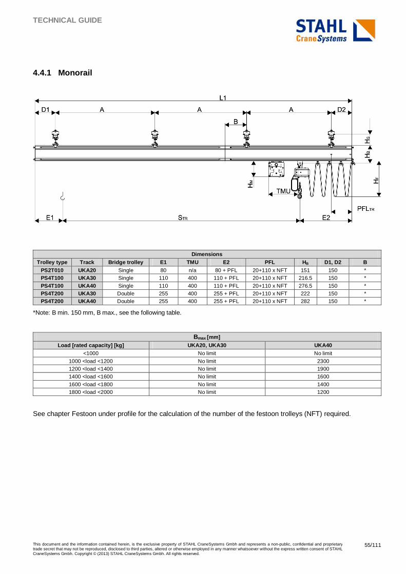
TECHNICAL GUIDE
This document and the information contained herein, is the exclusive property of STAHL CraneSystems Gmbh and represents a non-public, confidential and proprietary trade secret that may not be reproduced, disclosed to third parties, altered or otherwise employed in any manner whatsoever without the express written consent of STAHL CraneSystems Gmbh. Copyright © (2013) STAHL CraneSystems Gmbh. All rights reserved.
55/111
4.4.1 Monorail
Dimensions Trolley type Track Bridge trolley E1 TMU E2 PFL HB D1, D2 B
PS2T010 UKA20 Single 80 n/a 80 + PFL 20+110 x NFT 151 150 * PS4T100 UKA30 Single 110 400 110 + PFL 20+110 x NFT 216.5 150 *
PS4T100 UKA40 Single 110 400 110 + PFL 20+110 x NFT 276.5 150 * PS4T200 UKA30 Double 255 400 255 + PFL 20+110 x NFT 222 150 * PS4T200 UKA40 Double 255 400 255 + PFL 20+110 x NFT 282 150 *
*Note: B min. 150 mm, B max., see the following table.
Bmax [mm]
Load [rated capacity] [kg] UKA20, UKA30 UKA40 <1000 No limit No limit
1000 <load <1200 No limit 2300 1200 <load <1400 No limit 1900 1400 <load <1600 No limit 1600
1600 <load <1800 No limit 1400 1800 <load <2000 No limit 1200
See chapter Festoon under profile for the calculation of the number of the festoon trolleys (NFT) required.
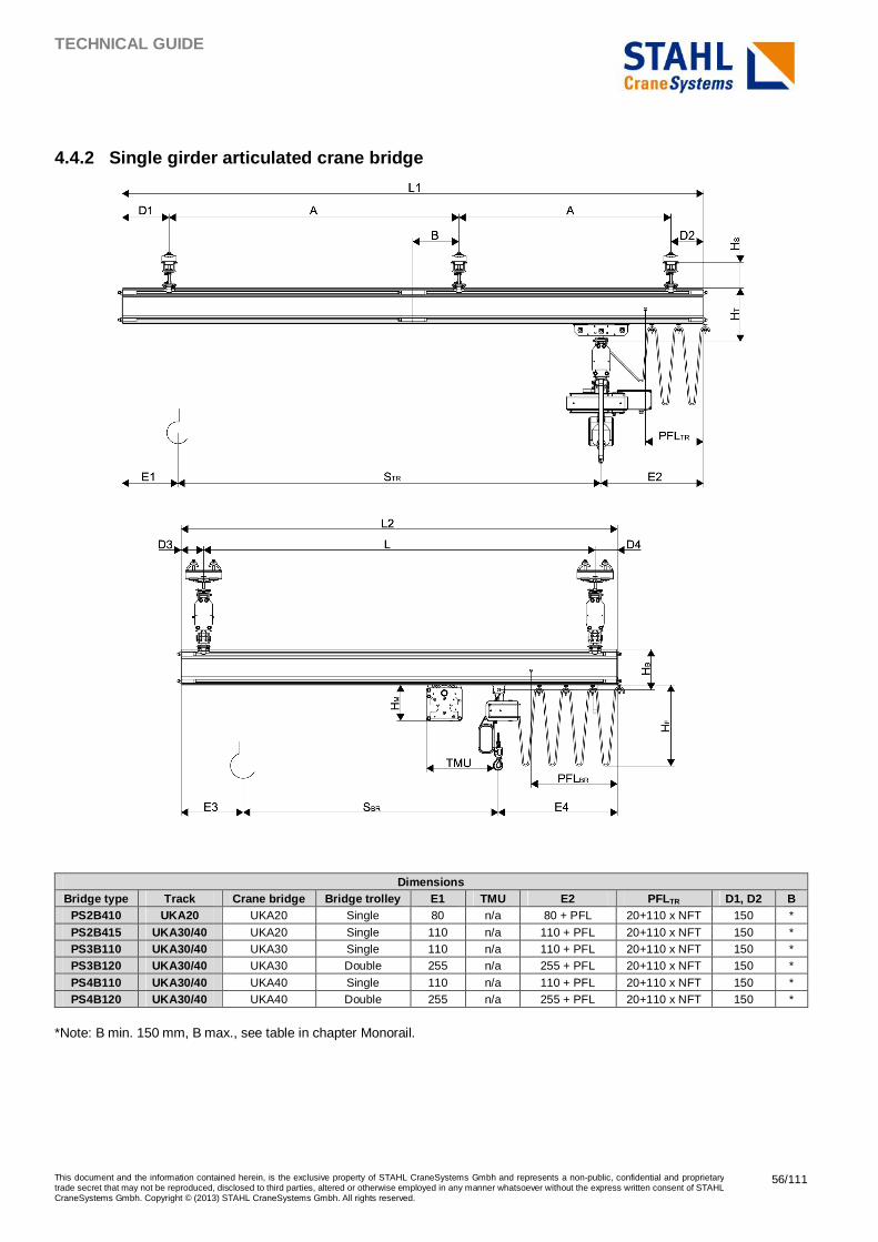
TECHNICAL GUIDE
This document and the information contained herein, is the exclusive property of STAHL CraneSystems Gmbh and represents a non-public, confidential and proprietary trade secret that may not be reproduced, disclosed to third parties, altered or otherwise employed in any manner whatsoever without the express written consent of STAHL CraneSystems Gmbh. Copyright © (2013) STAHL CraneSystems Gmbh. All rights reserved.
56/111
4.4.2 Single girder articulated crane bridge
Dimensions
Bridge type Track Crane bridge Bridge trolley E1 TMU E2 PFLTR D1, D2 B PS2B410 UKA20 UKA20 Single 80 n/a 80 + PFL 20+110 x NFT 150 *
PS2B415 UKA30/40 UKA20 Single 110 n/a 110 + PFL 20+110 x NFT 150 * PS3B110 UKA30/40 UKA30 Single 110 n/a 110 + PFL 20+110 x NFT 150 * PS3B120 UKA30/40 UKA30 Double 255 n/a 255 + PFL 20+110 x NFT 150 *
PS4B110 UKA30/40 UKA40 Single 110 n/a 110 + PFL 20+110 x NFT 150 * PS4B120 UKA30/40 UKA40 Double 255 n/a 255 + PFL 20+110 x NFT 150 *
*Note: B min. 150 mm, B max., see table in chapter Monorail.
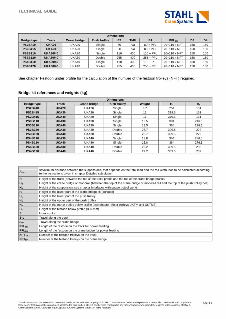
TECHNICAL GUIDE
This document and the information contained herein, is the exclusive property of STAHL CraneSystems Gmbh and represents a non-public, confidential and proprietary trade secret that may not be reproduced, disclosed to third parties, altered or otherwise employed in any manner whatsoever without the express written consent of STAHL CraneSystems Gmbh. Copyright © (2013) STAHL CraneSystems Gmbh. All rights reserved.
57/111
Dimensions Bridge type Track Crane bridge Push trolley E3 TMU E4 PFLBR D3 D4
PS2B410 UKA20 UKA20 Single 80 n/a 80 + PFL 20+110 x NFT 150 150 PS2B415 UKA20 UKA20 Single 80 n/a 80 + PFL 20+110 x NFT 150 150
PS3B110 UKA30/40 UKA30 Single 110 400 110 + PFL 20+110 x NFT 150 150 PS3B120 UKA30/40 UKA30 Double 255 400 255 + PFL 20+110 x NFT 150 150 PS4B110 UKA30/40 UKA40 Single 110 400 110 + PFL 20+110 x NFT 150 150 PS4B120 UKA30/40 UKA40 Double 255 400 255 + PFL 20+110 x NFT 150 150
See chapter Festoon under profile for the calculation of the number of the festoon trolleys (NFT) required.
Bridge kit references and weights (kg)
Dimensions Bridge type Track Crane bridge Push trolley Weight HT HB
PS2B410 UKA20 UKA20 Single 8.7 254 151 PS2B415 UKA30 UKA20 Single 11 319.5 151
PS2B415 UKA40 UKA20 Single 11 379.5 151 PS3B110 UKA30 UKA30 Single 13.5 304 216.5 PS3B110 UKA40 UKA30 Single 13.5 364 216.5
PS3B120 UKA30 UKA30 Double 28.7 309.5 222 PS3B120 UKA40 UKA30 Double 28.7 369.5 222 PS4B110 UKA30 UKA40 Single 13.8 304 276.5 PS4B110 UKA40 UKA40 Single 13.8 364 276.5
PS4B120 UKA30 UKA40 Double 29.2 309.5 282 PS4B120 UKA40 UKA40 Double 29.2 369.5 282
AMAX sMaximum distance between the suspensions, that depends on the total load and the rail width, has to be calculated according to the instructions given in chapter Detailed calculation
HT Height of the track (between the top of the track profile and the top of the crane bridge profile) HB Height of the crane bridge or monorail (between the top of the crane bridge or monorail rail and the top of the push trolley bolt)
HS Height of the suspension, see chapter Interfaces with support steel works HC Height of the lower part of the crane bridge kit (console) HL Height of the lower part of the push trolley HU Height of the upper part of the push trolley
HM Height of the motor trolley below profile (see chapter Motor trolleys UKTM and UKTM2) HF Height of the festoon below profile (800 mm) S Hook stroke
STR Travel along the track SBR Travel along the crane bridge PFLTR Length of the festoon on the track for power feeding PFLBR Length of the festoon on the crane bridge for power feeding
NFTTR Number of the festoon trolleys on the track NFTBR Number of the festoon trolleys on the crane bridge
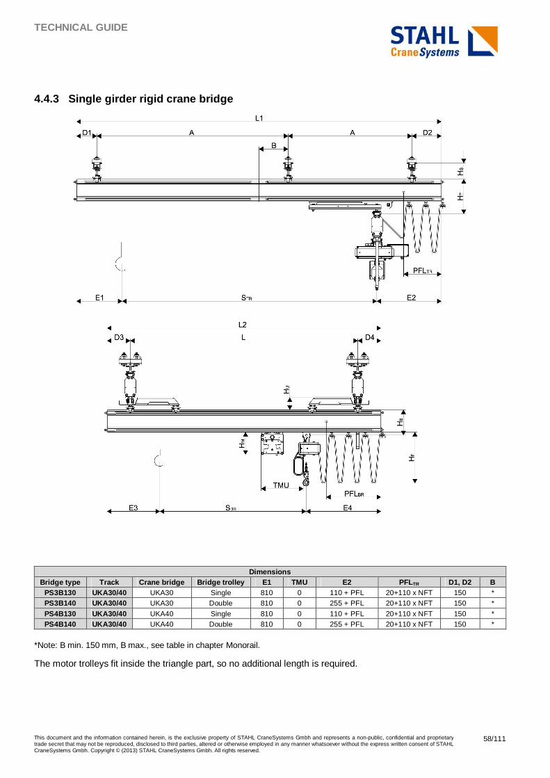
TECHNICAL GUIDE
This document and the information contained herein, is the exclusive property of STAHL CraneSystems Gmbh and represents a non-public, confidential and proprietary trade secret that may not be reproduced, disclosed to third parties, altered or otherwise employed in any manner whatsoever without the express written consent of STAHL CraneSystems Gmbh. Copyright © (2013) STAHL CraneSystems Gmbh. All rights reserved.
58/111
4.4.3 Single girder rigid crane bridge
Dimensions
Bridge type Track Crane bridge Bridge trolley E1 TMU E2 PFLTR D1, D2 B PS3B130 UKA30/40 UKA30 Single 810 0 110 + PFL 20+110 x NFT 150 * PS3B140 UKA30/40 UKA30 Double 810 0 255 + PFL 20+110 x NFT 150 *
PS4B130 UKA30/40 UKA40 Single 810 0 110 + PFL 20+110 x NFT 150 * PS4B140 UKA30/40 UKA40 Double 810 0 255 + PFL 20+110 x NFT 150 *
*Note: B min. 150 mm, B max., see table in chapter Monorail.
The motor trolleys fit inside the triangle part, so no additional length is required.
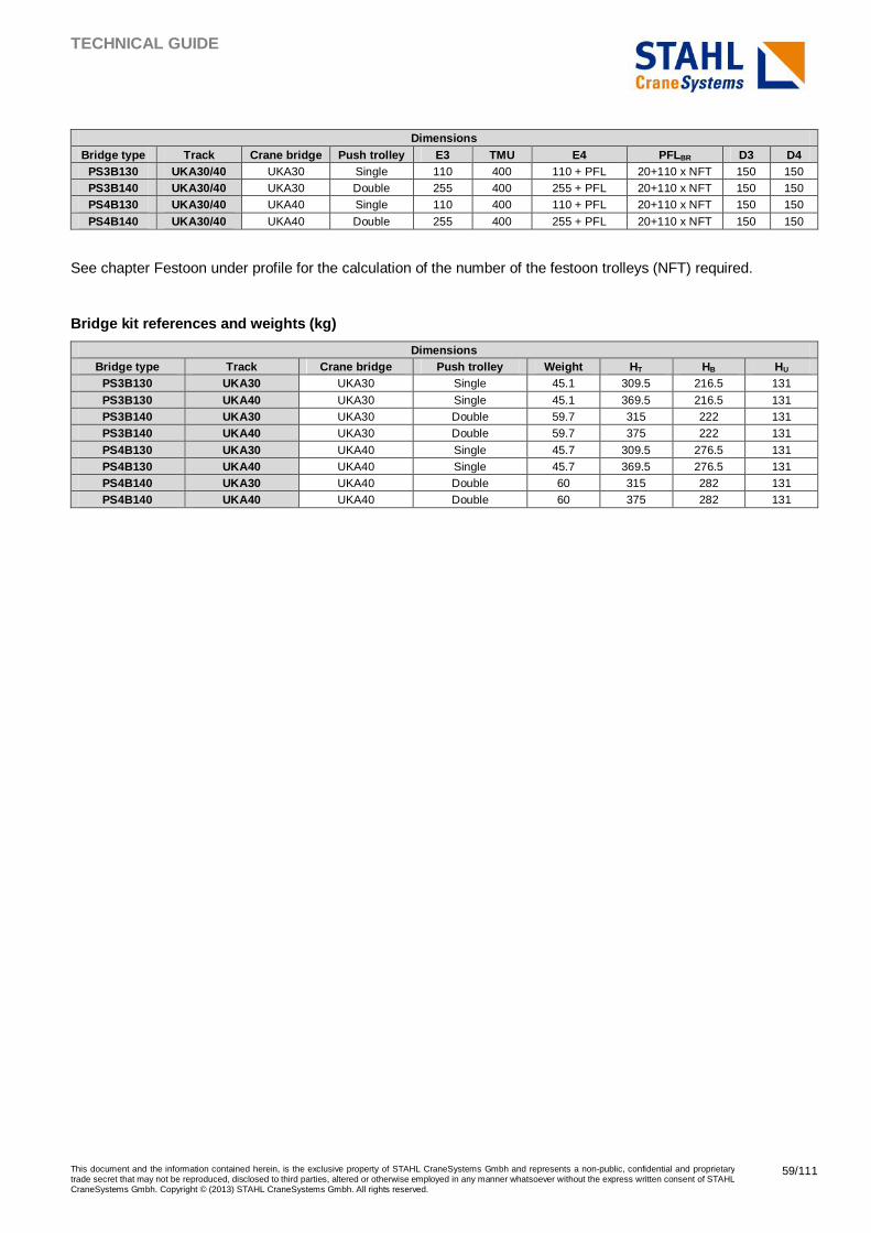
TECHNICAL GUIDE
This document and the information contained herein, is the exclusive property of STAHL CraneSystems Gmbh and represents a non-public, confidential and proprietary trade secret that may not be reproduced, disclosed to third parties, altered or otherwise employed in any manner whatsoever without the express written consent of STAHL CraneSystems Gmbh. Copyright © (2013) STAHL CraneSystems Gmbh. All rights reserved.
59/111
Dimensions
Bridge type Track Crane bridge Push trolley E3 TMU E4 PFLBR D3 D4 PS3B130 UKA30/40 UKA30 Single 110 400 110 + PFL 20+110 x NFT 150 150 PS3B140 UKA30/40 UKA30 Double 255 400 255 + PFL 20+110 x NFT 150 150 PS4B130 UKA30/40 UKA40 Single 110 400 110 + PFL 20+110 x NFT 150 150
PS4B140 UKA30/40 UKA40 Double 255 400 255 + PFL 20+110 x NFT 150 150
See chapter Festoon under profile for the calculation of the number of the festoon trolleys (NFT) required.
Bridge kit references and weights (kg)
Dimensions Bridge type Track Crane bridge Push trolley Weight HT HB HU
PS3B130 UKA30 UKA30 Single 45.1 309.5 216.5 131
PS3B130 UKA40 UKA30 Single 45.1 369.5 216.5 131 PS3B140 UKA30 UKA30 Double 59.7 315 222 131 PS3B140 UKA40 UKA30 Double 59.7 375 222 131
PS4B130 UKA30 UKA40 Single 45.7 309.5 276.5 131 PS4B130 UKA40 UKA40 Single 45.7 369.5 276.5 131 PS4B140 UKA30 UKA40 Double 60 315 282 131 PS4B140 UKA40 UKA40 Double 60 375 282 131
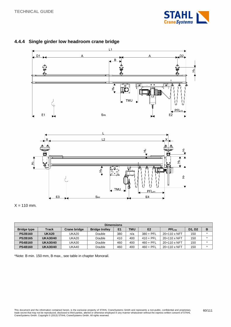
TECHNICAL GUIDE
This document and the information contained herein, is the exclusive property of STAHL CraneSystems Gmbh and represents a non-public, confidential and proprietary trade secret that may not be reproduced, disclosed to third parties, altered or otherwise employed in any manner whatsoever without the express written consent of STAHL CraneSystems Gmbh. Copyright © (2013) STAHL CraneSystems Gmbh. All rights reserved.
60/111
4.4.4 Single girder low headroom crane bridge
X = 110 mm.
Dimensions
Bridge type Track Crane bridge Bridge trolley E1 TMU E2 PFLTR D1, D2 B PS2B160 UKA20 UKA20 Double 380 n/a 380 + PFL 20+110 x NFT 150 * PS2B165 UKA30/40 UKA20 Double 410 400 410 + PFL 20+110 x NFT 150 * PS4B160 UKA30/40 UKA30 Double 460 400 460 + PFL 20+110 x NFT 150 * PS4B160 UKA30/40 UKA40 Double 460 400 460 + PFL 20+110 x NFT 150 *
*Note: B min. 150 mm, B max., see table in chapter Monorail.
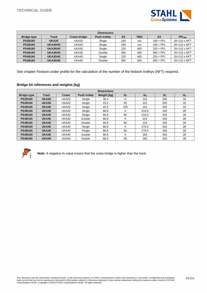
TECHNICAL GUIDE
This document and the information contained herein, is the exclusive property of STAHL CraneSystems Gmbh and represents a non-public, confidential and proprietary trade secret that may not be reproduced, disclosed to third parties, altered or otherwise employed in any manner whatsoever without the express written consent of STAHL CraneSystems Gmbh. Copyright © (2013) STAHL CraneSystems Gmbh. All rights reserved.
61/111
Dimensions
Bridge type Track Crane bridge Push trolley E3 TMU E4 PFLBR PS2B160 UKA20 UKA20 Single 190 n/a 190 + PFL 20+110 x NFT PS2B165 UKA30/40 UKA20 Single 190 n/a 190 + PFL 20+110 x NFT PS4B160 UKA30/40 UKA30 Single 220 400 220 + PFL 20+110 x NFT
PS4B160 UKA30/40 UKA30 Double 365 400 365 + PFL 20+110 x NFT PS4B160 UKA30/40 UKA40 Single 220 400 220 + PFL 20+110 x NFT PS4B160 UKA30/40 UKA40 Double 365 400 365 + PFL 20+110 x NFT
See chapter Festoon under profile for the calculation of the number of the festoon trolleys (NFT) required.
Bridge kit references and weights (kg)
Dimensions Bridge type Track Crane
bridge Push trolley Weight [kg] HT HB HC HU
PS2B160 UKA20 UKA20 Single 36.4 0 151 205 32 PS2B165 UKA30 UKA20 Single 43.3 65 151 205 32
PS2B165 UKA40 UKA20 Single 43.3 125 151 205 32 PS4B160 UKA30 UKA30 Single 86.8 0 216.5 326 28 PS4B160 UKA40 UKA30 Single 86.8 60 216.5 326 28 PS4B160 UKA30 UKA30 Double 86.8 0 222 326 28
PS4B160 UKA40 UKA30 Double 86.8 60 222 326 28 PS4B160 UKA30 UKA40 Single 86.8 0 276.5 326 28 PS4B160 UKA40 UKA40 Single 86.8 60 276.5 326 28
PS4B160 UKA30 UKA40 Double 86.8 0 282 326 28 PS4B160 UKA40 UKA40 Double 86.8 60 282 326 28
Note : A negative HT value means that the crane bridge is higher than the track.
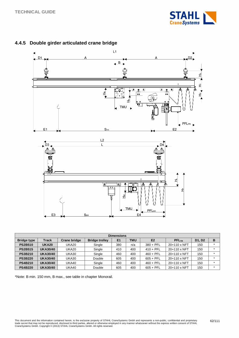
TECHNICAL GUIDE
This document and the information contained herein, is the exclusive property of STAHL CraneSystems Gmbh and represents a non-public, confidential and proprietary trade secret that may not be reproduced, disclosed to third parties, altered or otherwise employed in any manner whatsoever without the express written consent of STAHL CraneSystems Gmbh. Copyright © (2013) STAHL CraneSystems Gmbh. All rights reserved.
62/111
4.4.5 Double girder articulated crane bridge
Dimensions
Bridge type Track Crane bridge Bridge trolley E1 TMU E2 PFLTR D1, D2 B PS2B510 UKA20 UKA20 Single 380 n/a 380 + PFL 20+110 x NFT 150 * PS2B515 UKA30/40 UKA20 Single 410 400 410 + PFL 20+110 x NFT 150 *
PS3B210 UKA30/40 UKA30 Single 460 400 460 + PFL 20+110 x NFT 150 * PS3B220 UKA30/40 UKA30 Double 605 400 605 + PFL 20+110 x NFT 150 * PS4B210 UKA30/40 UKA40 Single 460 400 460 + PFL 20+110 x NFT 150 *
PS4B220 UKA30/40 UKA40 Double 605 400 605 + PFL 20+110 x NFT 150 *
*Note: B min. 150 mm, B max., see table in chapter Monorail.
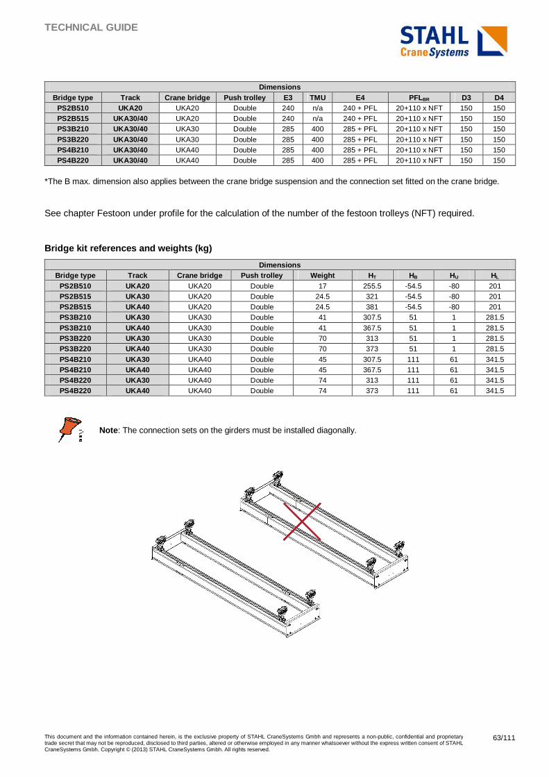
TECHNICAL GUIDE
This document and the information contained herein, is the exclusive property of STAHL CraneSystems Gmbh and represents a non-public, confidential and proprietary trade secret that may not be reproduced, disclosed to third parties, altered or otherwise employed in any manner whatsoever without the express written consent of STAHL CraneSystems Gmbh. Copyright © (2013) STAHL CraneSystems Gmbh. All rights reserved.
63/111
Dimensions
Bridge type Track Crane bridge Push trolley E3 TMU E4 PFLBR D3 D4 PS2B510 UKA20 UKA20 Double 240 n/a 240 + PFL 20+110 x NFT 150 150 PS2B515 UKA30/40 UKA20 Double 240 n/a 240 + PFL 20+110 x NFT 150 150 PS3B210 UKA30/40 UKA30 Double 285 400 285 + PFL 20+110 x NFT 150 150
PS3B220 UKA30/40 UKA30 Double 285 400 285 + PFL 20+110 x NFT 150 150 PS4B210 UKA30/40 UKA40 Double 285 400 285 + PFL 20+110 x NFT 150 150 PS4B220 UKA30/40 UKA40 Double 285 400 285 + PFL 20+110 x NFT 150 150
*The B max. dimension also applies between the crane bridge suspension and the connection set fitted on the crane bridge.
See chapter Festoon under profile for the calculation of the number of the festoon trolleys (NFT) required.
Bridge kit references and weights (kg)
Dimensions Bridge type Track Crane bridge Push trolley Weight HT HB HU HL
PS2B510 UKA20 UKA20 Double 17 255.5 -54.5 -80 201 PS2B515 UKA30 UKA20 Double 24.5 321 -54.5 -80 201 PS2B515 UKA40 UKA20 Double 24.5 381 -54.5 -80 201 PS3B210 UKA30 UKA30 Double 41 307.5 51 1 281.5
PS3B210 UKA40 UKA30 Double 41 367.5 51 1 281.5 PS3B220 UKA30 UKA30 Double 70 313 51 1 281.5 PS3B220 UKA40 UKA30 Double 70 373 51 1 281.5
PS4B210 UKA30 UKA40 Double 45 307.5 111 61 341.5 PS4B210 UKA40 UKA40 Double 45 367.5 111 61 341.5 PS4B220 UKA30 UKA40 Double 74 313 111 61 341.5 PS4B220 UKA40 UKA40 Double 74 373 111 61 341.5
Note : The connection sets on the girders must be installed diagonally.
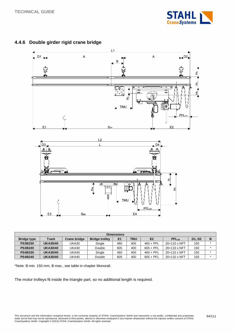
TECHNICAL GUIDE
This document and the information contained herein, is the exclusive property of STAHL CraneSystems Gmbh and represents a non-public, confidential and proprietary trade secret that may not be reproduced, disclosed to third parties, altered or otherwise employed in any manner whatsoever without the express written consent of STAHL CraneSystems Gmbh. Copyright © (2013) STAHL CraneSystems Gmbh. All rights reserved.
64/111
4.4.6 Double girder rigid crane bridge
Dimensions
Bridge type Track Crane bridge Bridge trolley E1 TMU E2 PFLTR D1, D2 B PS3B230 UKA30/40 UKA30 Single 460 400 460 + PFL 20+110 x NFT 150 *
PS3B240 UKA30/40 UKA30 Double 605 400 605 + PFL 20+110 x NFT 150 * PS4B230 UKA30/40 UKA40 Single 460 400 460 + PFL 20+110 x NFT 150 * PS4B240 UKA30/40 UKA40 Double 605 400 605 + PFL 20+110 x NFT 150 *
*Note: B min. 150 mm, B max., see table in chapter Monorail.
The motor trolleys fit inside the triangle part, so no additional length is required.
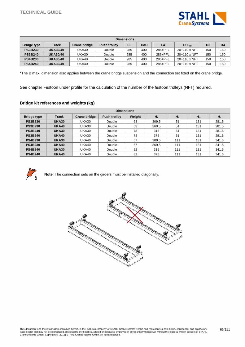
TECHNICAL GUIDE
This document and the information contained herein, is the exclusive property of STAHL CraneSystems Gmbh and represents a non-public, confidential and proprietary trade secret that may not be reproduced, disclosed to third parties, altered or otherwise employed in any manner whatsoever without the express written consent of STAHL CraneSystems Gmbh. Copyright © (2013) STAHL CraneSystems Gmbh. All rights reserved.
65/111
Dimensions
Bridge type Track Crane bridge Push trolley E3 TMU E4 PFLBR D3 D4 PS3B230 UKA30/40 UKA30 Double 285 400 285+PFL 20+110 x NFT 150 150 PS3B240 UKA30/40 UKA30 Double 285 400 285+PFL 20+110 x NFT 150 150 PS4B230 UKA30/40 UKA40 Double 285 400 285+PFL 20+110 x NFT 150 150
PS4B240 UKA30/40 UKA40 Double 285 400 285+PFL 20+110 x NFT 150 150
*The B max. dimension also applies between the crane bridge suspension and the connection set fitted on the crane bridge.
See chapter Festoon under profile for the calculation of the number of the festoon trolleys (NFT) required.
Bridge kit references and weights (kg)
Dimensions
Bridge type Track Crane bridge Push trolley Weight HT HB HU HL PS3B230 UKA30 UKA30 Double 63 309.5 51 131 281.5 PS3B230 UKA40 UKA30 Double 63 369.5 51 131 281.5 PS3B240 UKA30 UKA30 Double 78 315 51 131 281.5
PS3B240 UKA40 UKA30 Double 78 375 51 131 281.5 PS4B230 UKA30 UKA40 Double 67 309.5 111 131 341.5 PS4B230 UKA40 UKA40 Double 67 369.5 111 131 341.5 PS4B240 UKA30 UKA40 Double 82 315 111 131 341.5
PS4B240 UKA40 UKA40 Double 82 375 111 131 341.5
Note : The connection sets on the girders must be installed diagonally.
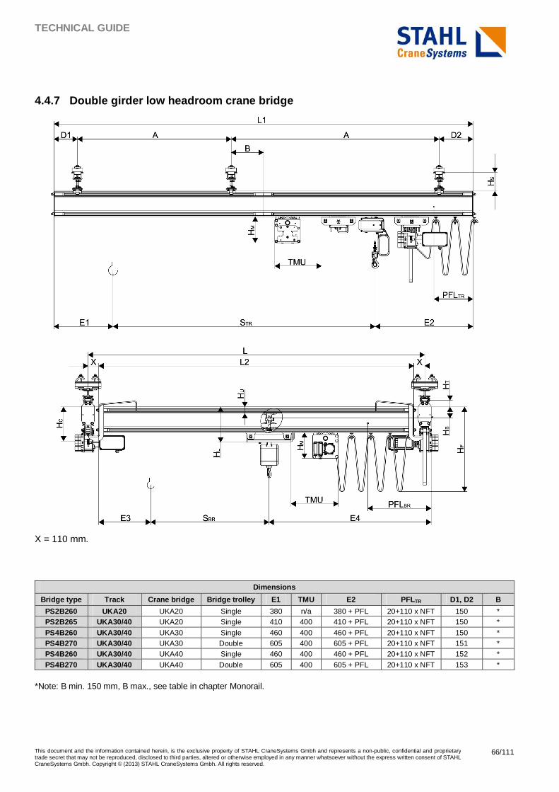
TECHNICAL GUIDE
This document and the information contained herein, is the exclusive property of STAHL CraneSystems Gmbh and represents a non-public, confidential and proprietary trade secret that may not be reproduced, disclosed to third parties, altered or otherwise employed in any manner whatsoever without the express written consent of STAHL CraneSystems Gmbh. Copyright © (2013) STAHL CraneSystems Gmbh. All rights reserved.
66/111
4.4.7 Double girder low headroom crane bridge
X = 110 mm.
Dimensions
Bridge type Track Crane bridge Bridge trolley E1 TMU E2 PFLTR D1, D2 B
PS2B260 UKA20 UKA20 Single 380 n/a 380 + PFL 20+110 x NFT 150 * PS2B265 UKA30/40 UKA20 Single 410 400 410 + PFL 20+110 x NFT 150 *
PS4B260 UKA30/40 UKA30 Single 460 400 460 + PFL 20+110 x NFT 150 * PS4B270 UKA30/40 UKA30 Double 605 400 605 + PFL 20+110 x NFT 151 * PS4B260 UKA30/40 UKA40 Single 460 400 460 + PFL 20+110 x NFT 152 *
PS4B270 UKA30/40 UKA40 Double 605 400 605 + PFL 20+110 x NFT 153 *
*Note: B min. 150 mm, B max., see table in chapter Monorail.
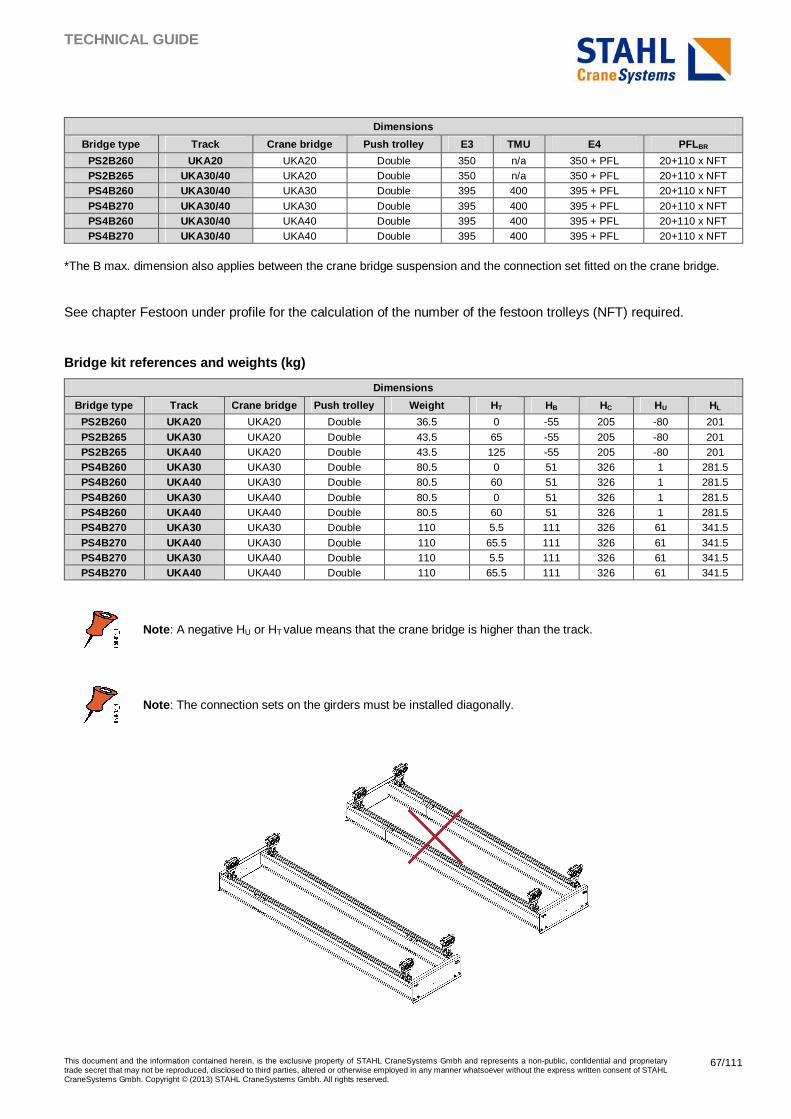
TECHNICAL GUIDE
This document and the information contained herein, is the exclusive property of STAHL CraneSystems Gmbh and represents a non-public, confidential and proprietary trade secret that may not be reproduced, disclosed to third parties, altered or otherwise employed in any manner whatsoever without the express written consent of STAHL CraneSystems Gmbh. Copyright © (2013) STAHL CraneSystems Gmbh. All rights reserved.
67/111
Dimensions
Bridge type Track Crane bridge Push trolley E3 TMU E4 PFLBR
PS2B260 UKA20 UKA20 Double 350 n/a 350 + PFL 20+110 x NFT PS2B265 UKA30/40 UKA20 Double 350 n/a 350 + PFL 20+110 x NFT PS4B260 UKA30/40 UKA30 Double 395 400 395 + PFL 20+110 x NFT
PS4B270 UKA30/40 UKA30 Double 395 400 395 + PFL 20+110 x NFT PS4B260 UKA30/40 UKA40 Double 395 400 395 + PFL 20+110 x NFT PS4B270 UKA30/40 UKA40 Double 395 400 395 + PFL 20+110 x NFT
*The B max. dimension also applies between the crane bridge suspension and the connection set fitted on the crane bridge.
See chapter Festoon under profile for the calculation of the number of the festoon trolleys (NFT) required.
Bridge kit references and weights (kg)
Dimensions
Bridge type Track Crane bridge Push trolley Weight HT HB HC HU HL
PS2B260 UKA20 UKA20 Double 36.5 0 -55 205 -80 201
PS2B265 UKA30 UKA20 Double 43.5 65 -55 205 -80 201 PS2B265 UKA40 UKA20 Double 43.5 125 -55 205 -80 201 PS4B260 UKA30 UKA30 Double 80.5 0 51 326 1 281.5 PS4B260 UKA40 UKA30 Double 80.5 60 51 326 1 281.5
PS4B260 UKA30 UKA40 Double 80.5 0 51 326 1 281.5 PS4B260 UKA40 UKA40 Double 80.5 60 51 326 1 281.5 PS4B270 UKA30 UKA30 Double 110 5.5 111 326 61 341.5
PS4B270 UKA40 UKA30 Double 110 65.5 111 326 61 341.5 PS4B270 UKA30 UKA40 Double 110 5.5 111 326 61 341.5 PS4B270 UKA40 UKA40 Double 110 65.5 111 326 61 341.5
Note : A negative HU or HT value means that the crane bridge is higher than the track.
Note : The connection sets on the girders must be installed diagonally.
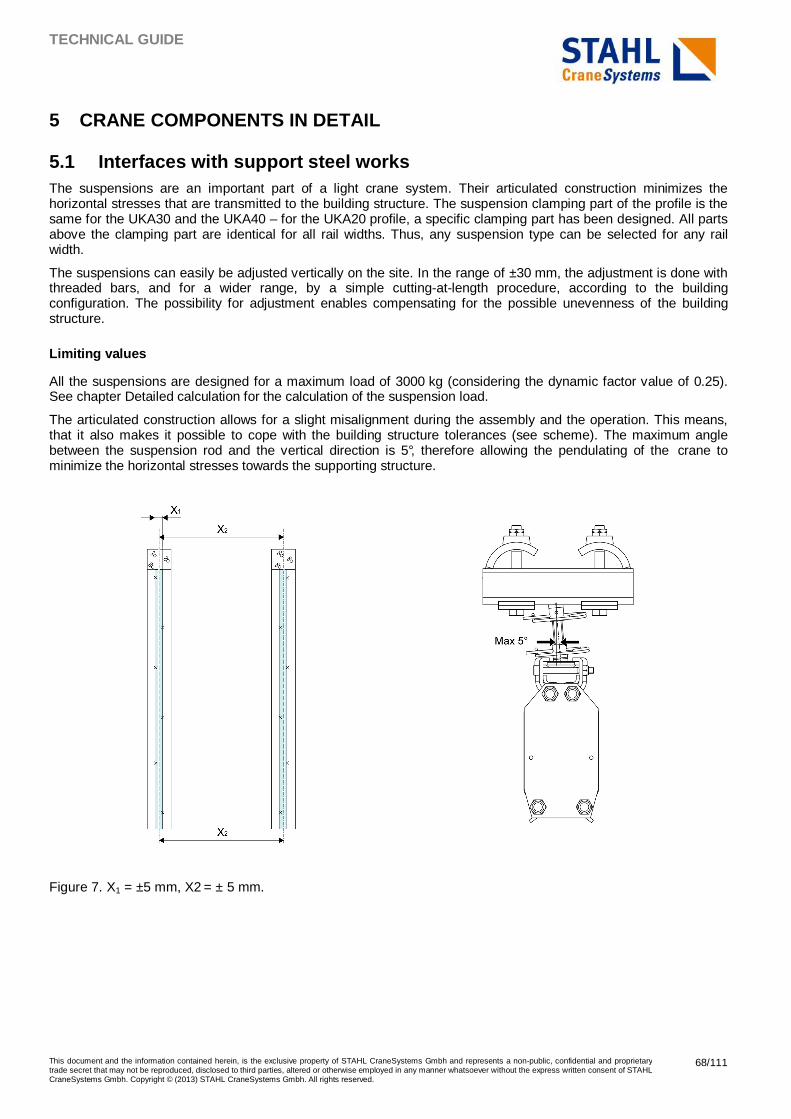
TECHNICAL GUIDE
This document and the information contained herein, is the exclusive property of STAHL CraneSystems Gmbh and represents a non-public, confidential and proprietary trade secret that may not be reproduced, disclosed to third parties, altered or otherwise employed in any manner whatsoever without the express written consent of STAHL CraneSystems Gmbh. Copyright © (2013) STAHL CraneSystems Gmbh. All rights reserved.
68/111
5 CRANE COMPONENTS IN DETAIL
5.1 Interfaces with support steel works The suspensions are an important part of a light crane system. Their articulated construction minimizes the horizontal stresses that are transmitted to the building structure. The suspension clamping part of the profile is the same for the UKA30 and the UKA40 – for the UKA20 profile, a specific clamping part has been designed. All parts above the clamping part are identical for all rail widths. Thus, any suspension type can be selected for any rail width.
The suspensions can easily be adjusted vertically on the site. In the range of ±30 mm, the adjustment is done with threaded bars, and for a wider range, by a simple cutting-at-length procedure, according to the building configuration. The possibility for adjustment enables compensating for the possible unevenness of the building structure.
Limiting values
All the suspensions are designed for a maximum load of 3000 kg (considering the dynamic factor value of 0.25). See chapter Detailed calculation for the calculation of the suspension load.
The articulated construction allows for a slight misalignment during the assembly and the operation. This means, that it also makes it possible to cope with the building structure tolerances (see scheme). The maximum angle between the suspension rod and the vertical direction is 5°, therefore allowing the pendulating of the crane to minimize the horizontal stresses towards the supporting structure.
Figure 7. X1 = ±5 mm, X2 = ± 5 mm.
TECHNICAL GUIDE
This document and the information contained herein, is the exclusive property of STAHL CraneSystems Gmbh and represents a non-public, confidential and proprietary trade secret that may not be reproduced, disclosed to third parties, altered or otherwise employed in any manner whatsoever without the express written consent of STAHL CraneSystems Gmbh. Copyright © (2013) STAHL CraneSystems Gmbh. All rights reserved.
69/111
Suspension range
The suspensions are available in different sizes and shapes, depending on the existing building structure. They can be connected to either an I- or an H-beam with a width of 80–300 mm, or directly to a ceiling or a concrete beam.
For information on suspensions for inclined building structures, see chapter Articulated suspensions.
Safety locking
When the height is adjusted, the threaded rod is locked with safety pins at the top and at the bottom, to prevent any rotation of the suspension nuts.
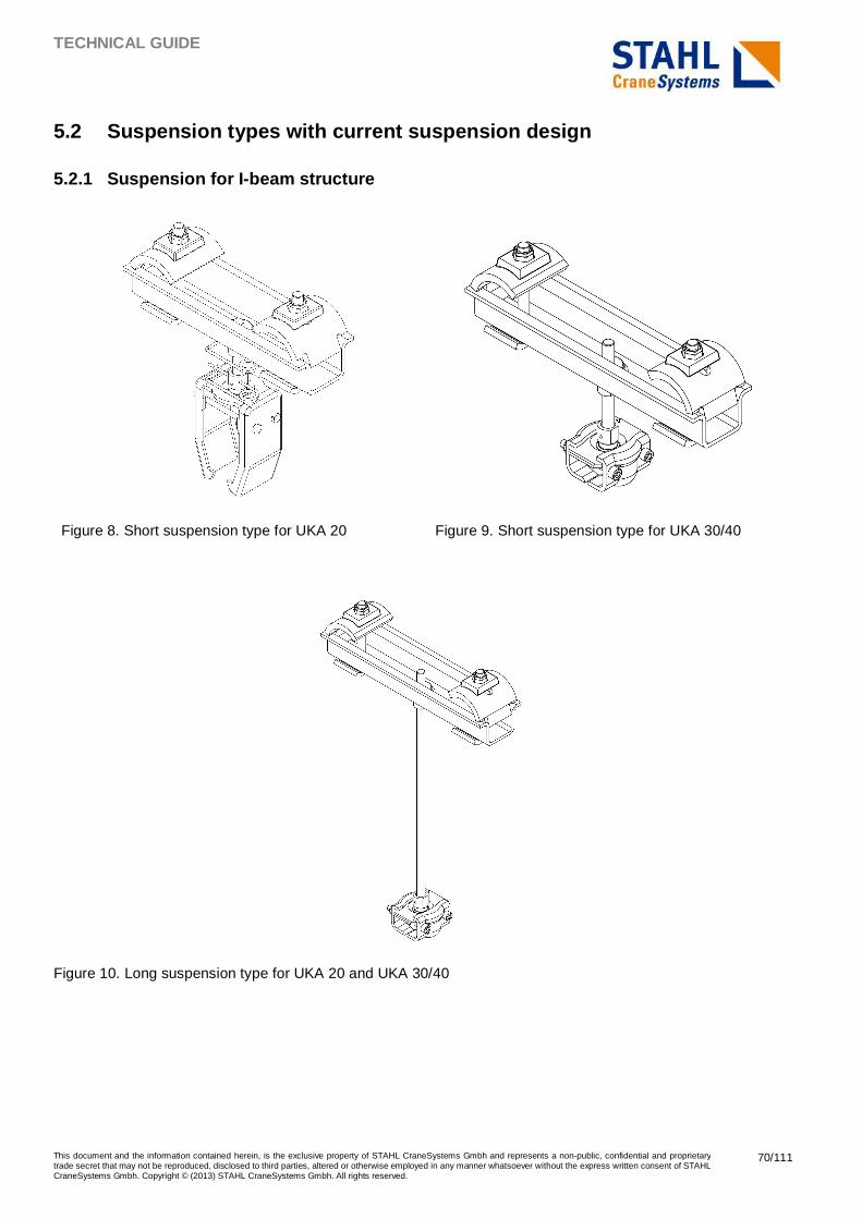
TECHNICAL GUIDE
This document and the information contained herein, is the exclusive property of STAHL CraneSystems Gmbh and represents a non-public, confidential and proprietary trade secret that may not be reproduced, disclosed to third parties, altered or otherwise employed in any manner whatsoever without the express written consent of STAHL CraneSystems Gmbh. Copyright © (2013) STAHL CraneSystems Gmbh. All rights reserved.
70/111
5.2 Suspension types with current suspension design
5.2.1 Suspension for I-beam structure
Figure 8. Short suspension type for UKA 20 Figure 9. Short suspension type for UKA 30/40
Figure 10. Long suspension type for UKA 20 and UKA 30/40
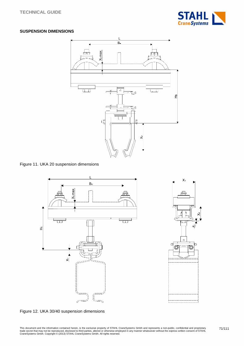
TECHNICAL GUIDE
This document and the information contained herein, is the exclusive property of STAHL CraneSystems Gmbh and represents a non-public, confidential and proprietary trade secret that may not be reproduced, disclosed to third parties, altered or otherwise employed in any manner whatsoever without the express written consent of STAHL CraneSystems Gmbh. Copyright © (2013) STAHL CraneSystems Gmbh. All rights reserved.
71/111
SUSPENSION DIMENSIONS
Figure 11. UKA 20 suspension dimensions
Figure 12. UKA 30/40 suspension dimensions
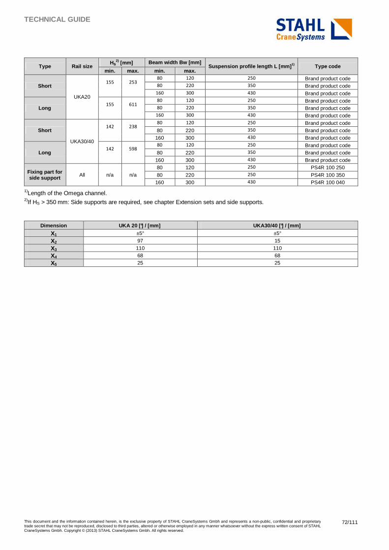
TECHNICAL GUIDE
This document and the information contained herein, is the exclusive property of STAHL CraneSystems Gmbh and represents a non-public, confidential and proprietary trade secret that may not be reproduced, disclosed to third parties, altered or otherwise employed in any manner whatsoever without the express written consent of STAHL CraneSystems Gmbh. Copyright © (2013) STAHL CraneSystems Gmbh. All rights reserved.
72/111
Type Rail size Hs
2) [mm] Beam width Bw [mm] Suspension profile length L [mm] 1) Type code
min. max. min. max.
Short
UKA20
155 253 80 120 250 Brand product code 80 220 350 Brand product code
160 300 430 Brand product code
Long 155 611
80 120 250 Brand product code 80 220 350 Brand product code
160 300 430 Brand product code
Short
UKA30/40
142 238 80 120 250 Brand product code 80 220 350 Brand product code
160 300 430 Brand product code
Long 142 598
80 120 250 Brand product code 80 220 350 Brand product code
160 300 430 Brand product code
Fixing part for side support All n/a n/a
80 120 250 PS4R 100 250
80 220 250 PS4R 100 350 160 300 430 PS4R 100 040
1)Length of the Omega channel. 2)If HS > 350 mm: Side supports are required, see chapter Extension sets and side supports.
Dimension UKA 20 [°] / [mm] UKA30/40 [°] / [mm]
X1 ±5° ±5°
X2 97 15
X3 110 110
X4 68 68
X5 25 25
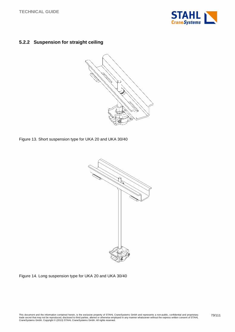
TECHNICAL GUIDE
This document and the information contained herein, is the exclusive property of STAHL CraneSystems Gmbh and represents a non-public, confidential and proprietary trade secret that may not be reproduced, disclosed to third parties, altered or otherwise employed in any manner whatsoever without the express written consent of STAHL CraneSystems Gmbh. Copyright © (2013) STAHL CraneSystems Gmbh. All rights reserved.
73/111
5.2.2 Suspension for straight ceiling
Figure 13. Short suspension type for UKA 20 and UKA 30/40
Figure 14. Long suspension type for UKA 20 and UKA 30/40
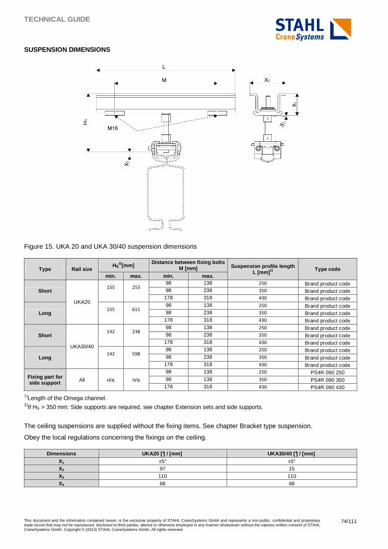
TECHNICAL GUIDE
This document and the information contained herein, is the exclusive property of STAHL CraneSystems Gmbh and represents a non-public, confidential and proprietary trade secret that may not be reproduced, disclosed to third parties, altered or otherwise employed in any manner whatsoever without the express written consent of STAHL CraneSystems Gmbh. Copyright © (2013) STAHL CraneSystems Gmbh. All rights reserved.
74/111
SUSPENSION DIMENSIONS
Figure 15. UKA 20 and UKA 30/40 suspension dimensions
Type Rail size HS
2)[mm] Distance between fixing bolts
M [mm] Suspension profile length L [mm] 1)
Type code min. max. min. max.
Short
UKA20
155 253
98 138 250 Brand product code 98 238 350 Brand product code
178 318 430 Brand product code
Long 155 611
98 138 250 Brand product code 98 238 350 Brand product code
178 318 430 Brand product code
Short
UKA30/40
142 238 98 138 250 Brand product code 98 238 350 Brand product code
178 318 430 Brand product code
Long 142 598
98 138 250 Brand product code 98 238 350 Brand product code
178 318 430 Brand product code
Fixing part for side support All n/a n/a
98 138 250 PS4R 090 250 98 138 350 PS4R 090 350
178 318 430 PS4R 090 430
1)Length of the Omega channel. 2)If HS > 350 mm: Side supports are required, see chapter Extension sets and side supports.
The ceiling suspensions are supplied without the fixing items. See chapter Bracket type suspension.
Obey the local regulations concerning the fixings on the ceiling.
Dimensions UKA20 [°] / [mm] UKA30/40 [°] / [mm] X1 ±5° ±5° X2 97 15
X3 110 110 X4 68 68
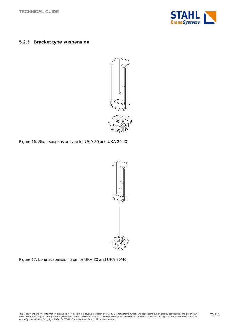
TECHNICAL GUIDE
This document and the information contained herein, is the exclusive property of STAHL CraneSystems Gmbh and represents a non-public, confidential and proprietary trade secret that may not be reproduced, disclosed to third parties, altered or otherwise employed in any manner whatsoever without the express written consent of STAHL CraneSystems Gmbh. Copyright © (2013) STAHL CraneSystems Gmbh. All rights reserved.
75/111
5.2.3 Bracket type suspension
Figure 16. Short suspension type for UKA 20 and UKA 30/40
Figure 17. Long suspension type for UKA 20 and UKA 30/40
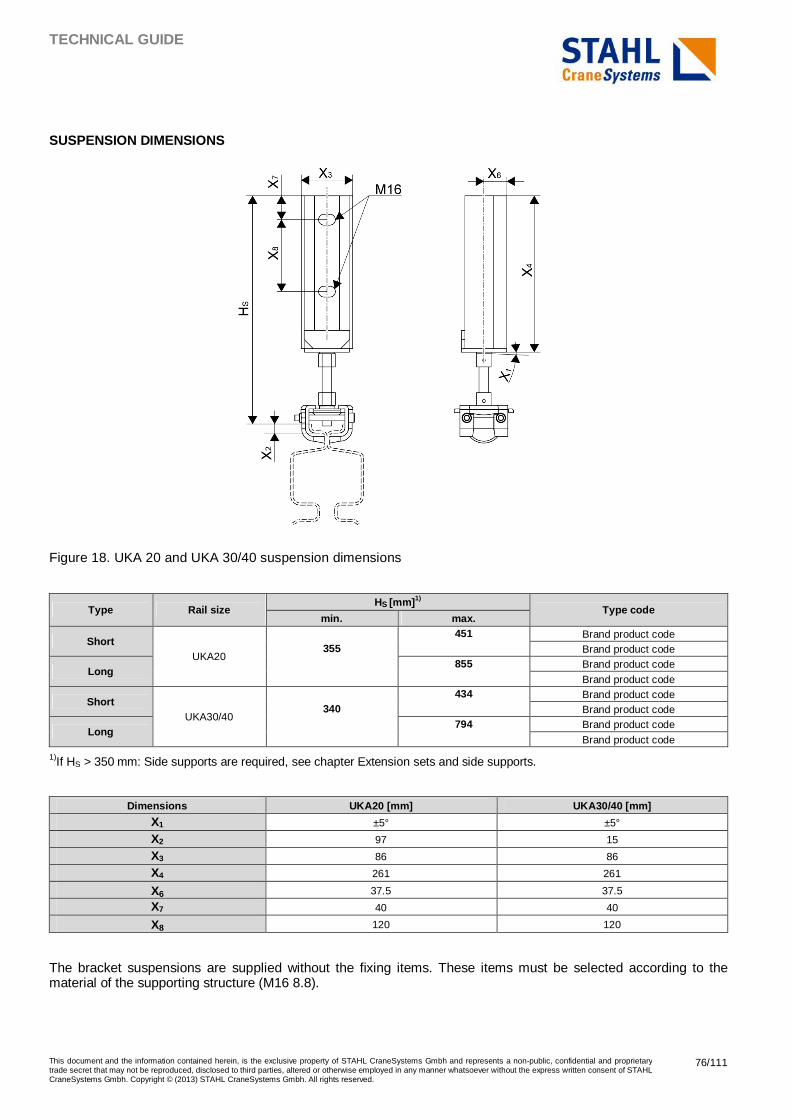
TECHNICAL GUIDE
This document and the information contained herein, is the exclusive property of STAHL CraneSystems Gmbh and represents a non-public, confidential and proprietary trade secret that may not be reproduced, disclosed to third parties, altered or otherwise employed in any manner whatsoever without the express written consent of STAHL CraneSystems Gmbh. Copyright © (2013) STAHL CraneSystems Gmbh. All rights reserved.
76/111
SUSPENSION DIMENSIONS
Figure 18. UKA 20 and UKA 30/40 suspension dimensions
Type Rail size HS [mm] 1)
Type code min. max.
Short UKA20
355 451 Brand product code
Brand product code
Long 855 Brand product code
Brand product code
Short UKA30/40
340 434 Brand product code
Brand product code
Long 794 Brand product code
Brand product code
1)If HS > 350 mm: Side supports are required, see chapter Extension sets and side supports.
Dimensions UKA20 [mm] UKA30/40 [mm]
X1 ±5° ±5°
X2 97 15
X3 86 86
X4 261 261
X6 37.5 37.5
X7 40 40
X8 120 120
The bracket suspensions are supplied without the fixing items. These items must be selected according to the material of the supporting structure (M16 8.8).
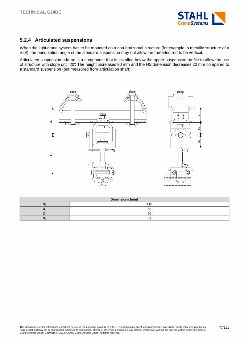
TECHNICAL GUIDE
This document and the information contained herein, is the exclusive property of STAHL CraneSystems Gmbh and represents a non-public, confidential and proprietary trade secret that may not be reproduced, disclosed to third parties, altered or otherwise employed in any manner whatsoever without the express written consent of STAHL CraneSystems Gmbh. Copyright © (2013) STAHL CraneSystems Gmbh. All rights reserved.
77/111
5.2.4 Articulated suspensions
When the light crane system has to be mounted on a non-horizontal structure (for example, a metallic structure of a roof), the pendulation angle of the standard suspension may not allow the threaded rod to be vertical.
Articulated suspension add-on is a component that is installed below the upper suspension profile to allow the use of structure with slope until 20°. The height incre ases 90 mm and the HS dimension decreases 20 mm compared to a standard suspension (but measured from articulation shaft).
Dimensions [mm] X1 110 X2 60 X3 50
X4 69
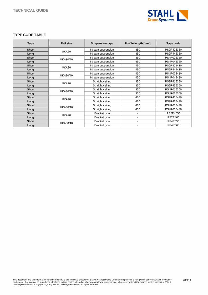
TECHNICAL GUIDE
This document and the information contained herein, is the exclusive property of STAHL CraneSystems Gmbh and represents a non-public, confidential and proprietary trade secret that may not be reproduced, disclosed to third parties, altered or otherwise employed in any manner whatsoever without the express written consent of STAHL CraneSystems Gmbh. Copyright © (2013) STAHL CraneSystems Gmbh. All rights reserved.
78/111
TYPE CODE TABLE
Type Rail size Suspension type Profile length [mm] Type code
Short UKA20
I-beam suspension 350 PS2R425350 Long I-beam suspension 350 PS2R445350
Short UKA30/40
I-beam suspension 350 PS4R025350 Long I-beam suspension 350 PS4R045350 Short
UKA20 I-beam suspension 430 PS2R425430
Long I-beam suspension 430 PS2R445430
Short UKA30/40
I-beam suspension 430 PS4R025430 Long I-beam suspension 430 PS4R045430 Short
UKA20 Straight ceiling 350 PS2R415350
Long Straight ceiling 350 PS2R435350 Short
UKA30/40 Straight ceiling 350 PS4R015350
Long Straight ceiling 350 PS4R035350 Short
UKA20 Straight ceiling 430 PS2R415430
Long Straight ceiling 430 PS2R435430 Short
UKA30/40 Straight ceiling 430 PS4R015430
Long Straight ceiling 430 PS4R035430
Short UKA20
Bracket type - PS2R4055 Long Bracket type - PS2R465 Short
UKA30/40 Bracket type - PS4R055
Long Bracket type - PS4R065
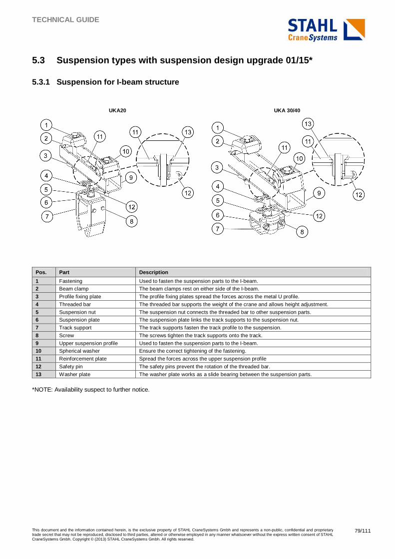
TECHNICAL GUIDE
This document and the information contained herein, is the exclusive property of STAHL CraneSystems Gmbh and represents a non-public, confidential and proprietary trade secret that may not be reproduced, disclosed to third parties, altered or otherwise employed in any manner whatsoever without the express written consent of STAHL CraneSystems Gmbh. Copyright © (2013) STAHL CraneSystems Gmbh. All rights reserved.
79/111
5.3 Suspension types with suspension design upgrade 01/15*
5.3.1 Suspension for I-beam structure
UKA20 UKA 30/40
Pos. Part Description
1 Fastening Used to fasten the suspension parts to the I-beam.
2 Beam clamp The beam clamps rest on either side of the I-beam.
3 Profile fixing plate The profile fixing plates spread the forces across the metal U profile.
4 Threaded bar The threaded bar supports the weight of the crane and allows height adjustment.
5 Suspension nut The suspension nut connects the threaded bar to other suspension parts.
6 Suspension plate The suspension plate links the track supports to the suspension nut.
7 Track support The track supports fasten the track profile to the suspension.
8 Screw The screws tighten the track supports onto the track.
9 Upper suspension profile Used to fasten the suspension parts to the I-beam.
10 Spherical washer Ensure the correct tightening of the fastening.
11 Reinforcement plate Spread the forces across the upper suspension profile
12 Safety pin The safety pins prevent the rotation of the threaded bar.
13 Washer plate The washer plate works as a slide bearing between the suspension parts.
*NOTE: Availability suspect to further notice.
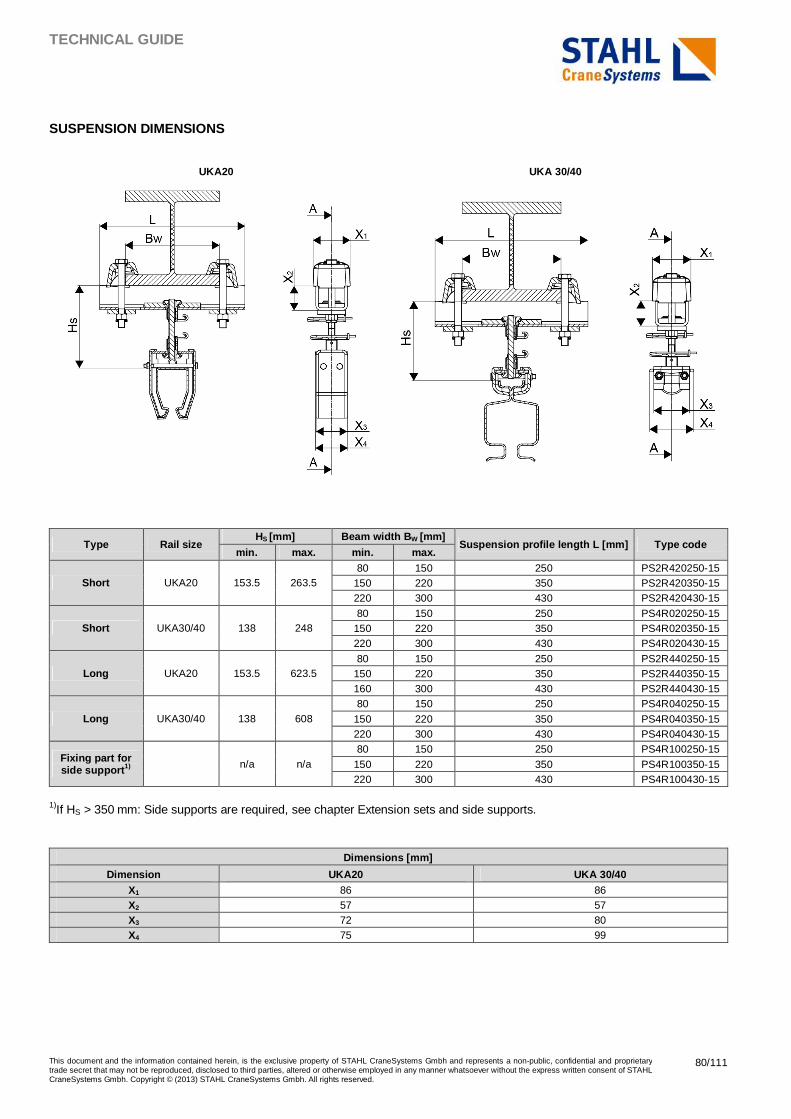
TECHNICAL GUIDE
This document and the information contained herein, is the exclusive property of STAHL CraneSystems Gmbh and represents a non-public, confidential and proprietary trade secret that may not be reproduced, disclosed to third parties, altered or otherwise employed in any manner whatsoever without the express written consent of STAHL CraneSystems Gmbh. Copyright © (2013) STAHL CraneSystems Gmbh. All rights reserved.
80/111
SUSPENSION DIMENSIONS
UKA20 UKA 30/40
Type Rail size HS [mm] Beam width B W [mm]
Suspension profile length L [mm] Type code min. max. min. max.
Short UKA20 153.5 263.5 80 150 250 PS2R420250-15
150 220 350 PS2R420350-15 220 300 430 PS2R420430-15
Short UKA30/40 138 248 80 150 250 PS4R020250-15
150 220 350 PS4R020350-15 220 300 430 PS4R020430-15
Long UKA20 153.5 623.5 80 150 250 PS2R440250-15
150 220 350 PS2R440350-15 160 300 430 PS2R440430-15
Long UKA30/40 138 608 80 150 250 PS4R040250-15
150 220 350 PS4R040350-15 220 300 430 PS4R040430-15
Fixing part for side support 1) n/a n/a
80 150 250 PS4R100250-15
150 220 350 PS4R100350-15 220 300 430 PS4R100430-15
1)If HS > 350 mm: Side supports are required, see chapter Extension sets and side supports.
Dimensions [mm]
Dimension UKA20 UKA 30/40 X1 86 86 X2 57 57 X3 72 80 X4 75 99
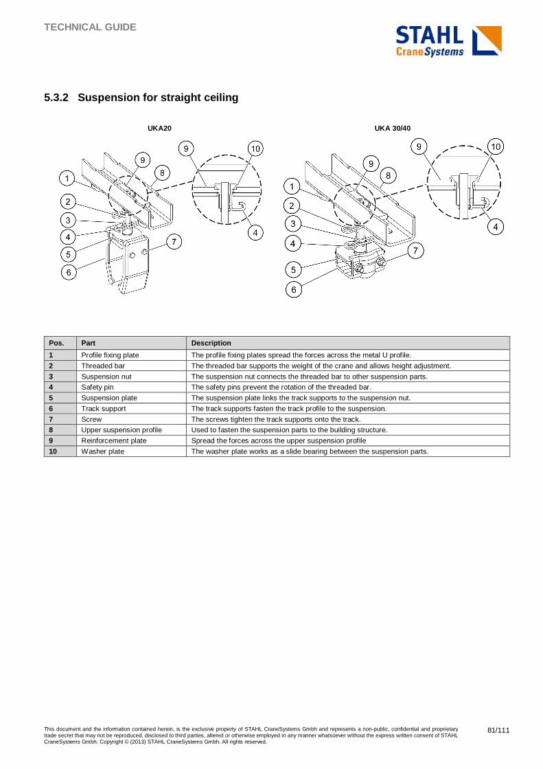
TECHNICAL GUIDE
This document and the information contained herein, is the exclusive property of STAHL CraneSystems Gmbh and represents a non-public, confidential and proprietary trade secret that may not be reproduced, disclosed to third parties, altered or otherwise employed in any manner whatsoever without the express written consent of STAHL CraneSystems Gmbh. Copyright © (2013) STAHL CraneSystems Gmbh. All rights reserved.
81/111
5.3.2 Suspension for straight ceiling
UKA20 UKA 30/40
Pos. Part Description
1 Profile fixing plate The profile fixing plates spread the forces across the metal U profile.
2 Threaded bar The threaded bar supports the weight of the crane and allows height adjustment.
3 Suspension nut The suspension nut connects the threaded bar to other suspension parts.
4 Safety pin The safety pins prevent the rotation of the threaded bar.
5 Suspension plate The suspension plate links the track supports to the suspension nut.
6 Track support The track supports fasten the track profile to the suspension.
7 Screw The screws tighten the track supports onto the track.
8 Upper suspension profile Used to fasten the suspension parts to the building structure.
9 Reinforcement plate Spread the forces across the upper suspension profile
10 Washer plate The washer plate works as a slide bearing between the suspension parts.
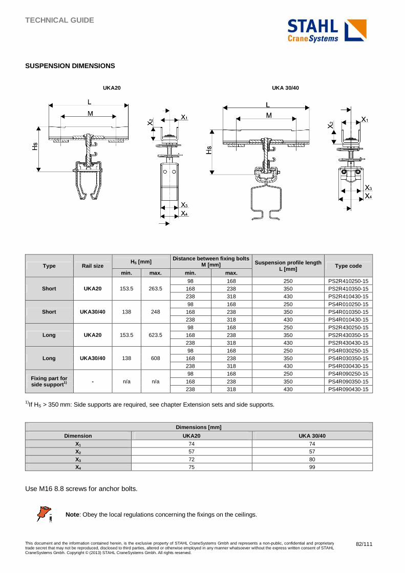
TECHNICAL GUIDE
This document and the information contained herein, is the exclusive property of STAHL CraneSystems Gmbh and represents a non-public, confidential and proprietary trade secret that may not be reproduced, disclosed to third parties, altered or otherwise employed in any manner whatsoever without the express written consent of STAHL CraneSystems Gmbh. Copyright © (2013) STAHL CraneSystems Gmbh. All rights reserved.
82/111
SUSPENSION DIMENSIONS
UKA20 UKA 30/40
Type Rail size HS [mm] Distance between fixing bolts
M [mm] Suspension profile length L [mm] Type code
min. max. min. max.
Short UKA20 153.5 263.5 98 168 250 PS2R410250-15
168 238 350 PS2R410350-15 238 318 430 PS2R410430-15
Short UKA30/40 138 248 98 168 250 PS4R010250-15
168 238 350 PS4R010350-15 238 318 430 PS4R010430-15
Long UKA20 153.5 623.5 98 168 250 PS2R430250-15
168 238 350 PS2R430350-15 238 318 430 PS2R430430-15
Long UKA30/40 138 608 98 168 250 PS4R030250-15
168 238 350 PS4R030350-15 238 318 430 PS4R030430-15
Fixing part for side support 1) - n/a n/a
98 168 250 PS4R090250-15
168 238 350 PS4R090350-15 238 318 430 PS4R090430-15
1)If HS > 350 mm: Side supports are required, see chapter Extension sets and side supports.
Dimensions [mm]
Dimension UKA20 UKA 30/40 X1 74 74 X2 57 57
X3 72 80 X4 75 99
Use M16 8.8 screws for anchor bolts.
Note : Obey the local regulations concerning the fixings on the ceilings.
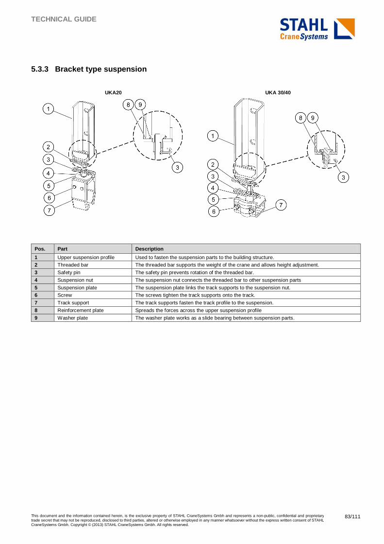
TECHNICAL GUIDE
This document and the information contained herein, is the exclusive property of STAHL CraneSystems Gmbh and represents a non-public, confidential and proprietary trade secret that may not be reproduced, disclosed to third parties, altered or otherwise employed in any manner whatsoever without the express written consent of STAHL CraneSystems Gmbh. Copyright © (2013) STAHL CraneSystems Gmbh. All rights reserved.
83/111
5.3.3 Bracket type suspension
UKA20 UKA 30/40
Pos. Part Description
1 Upper suspension profile Used to fasten the suspension parts to the building structure.
2 Threaded bar The threaded bar supports the weight of the crane and allows height adjustment.
3 Safety pin The safety pin prevents rotation of the threaded bar.
4 Suspension nut The suspension nut connects the threaded bar to other suspension parts
5 Suspension plate The suspension plate links the track supports to the suspension nut.
6 Screw The screws tighten the track supports onto the track.
7 Track support The track supports fasten the track profile to the suspension.
8 Reinforcement plate Spreads the forces across the upper suspension profile
9 Washer plate The washer plate works as a slide bearing between suspension parts.

TECHNICAL GUIDE
This document and the information contained herein, is the exclusive property of STAHL CraneSystems Gmbh and represents a non-public, confidential and proprietary trade secret that may not be reproduced, disclosed to third parties, altered or otherwise employed in any manner whatsoever without the express written consent of STAHL CraneSystems Gmbh. Copyright © (2013) STAHL CraneSystems Gmbh. All rights reserved.
84/111
SUSPENSION DIMENSIONS
UKA20 UKA 30/40
Type Rail HS [mm] Height between fixing bolts
[mm] Bracket height [mm] Type code min. max.
Short UKA20 203.5 313.5 120 261 PS2R450-15 Short UKA30/40 188 298 120 261 PS4R050-15 Long UKA20 203.5 673.5 120 261 PS2R460-15
Long UKA30/40 188 658 120 261 PS4R060-15 Fixing part for side support 1)
- n/a n/a 120 261 PS4R110-15
1)If HS > 350 mm: Side supports are required, see chapter Extension sets and side supports.
Dimensions [mm]
Dimension UKA20 UKA 30/40 X1 76 76 X2 70 70
X3 40 40 X4 120 120 X5 6 6 X6 10 10
X7 86 86 X8 261 261 X9 72 80
X10 75 99
Use M16 8.8 screws for anchor bolts.
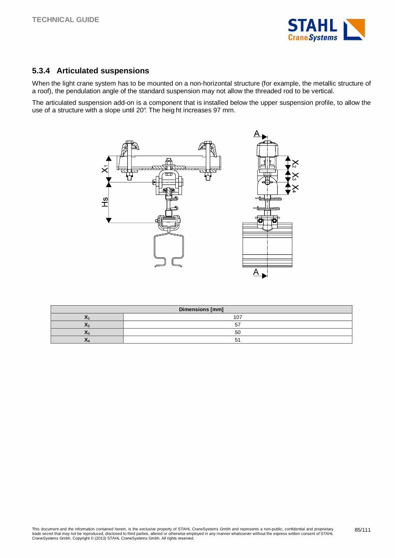
TECHNICAL GUIDE
This document and the information contained herein, is the exclusive property of STAHL CraneSystems Gmbh and represents a non-public, confidential and proprietary trade secret that may not be reproduced, disclosed to third parties, altered or otherwise employed in any manner whatsoever without the express written consent of STAHL CraneSystems Gmbh. Copyright © (2013) STAHL CraneSystems Gmbh. All rights reserved.
85/111
5.3.4 Articulated suspensions
When the light crane system has to be mounted on a non-horizontal structure (for example, the metallic structure of a roof), the pendulation angle of the standard suspension may not allow the threaded rod to be vertical.
The articulated suspension add-on is a component that is installed below the upper suspension profile, to allow the use of a structure with a slope until 20°. The heig ht increases 97 mm.
Dimensions [mm]
X1 107 X2 57
X3 50 X4 51
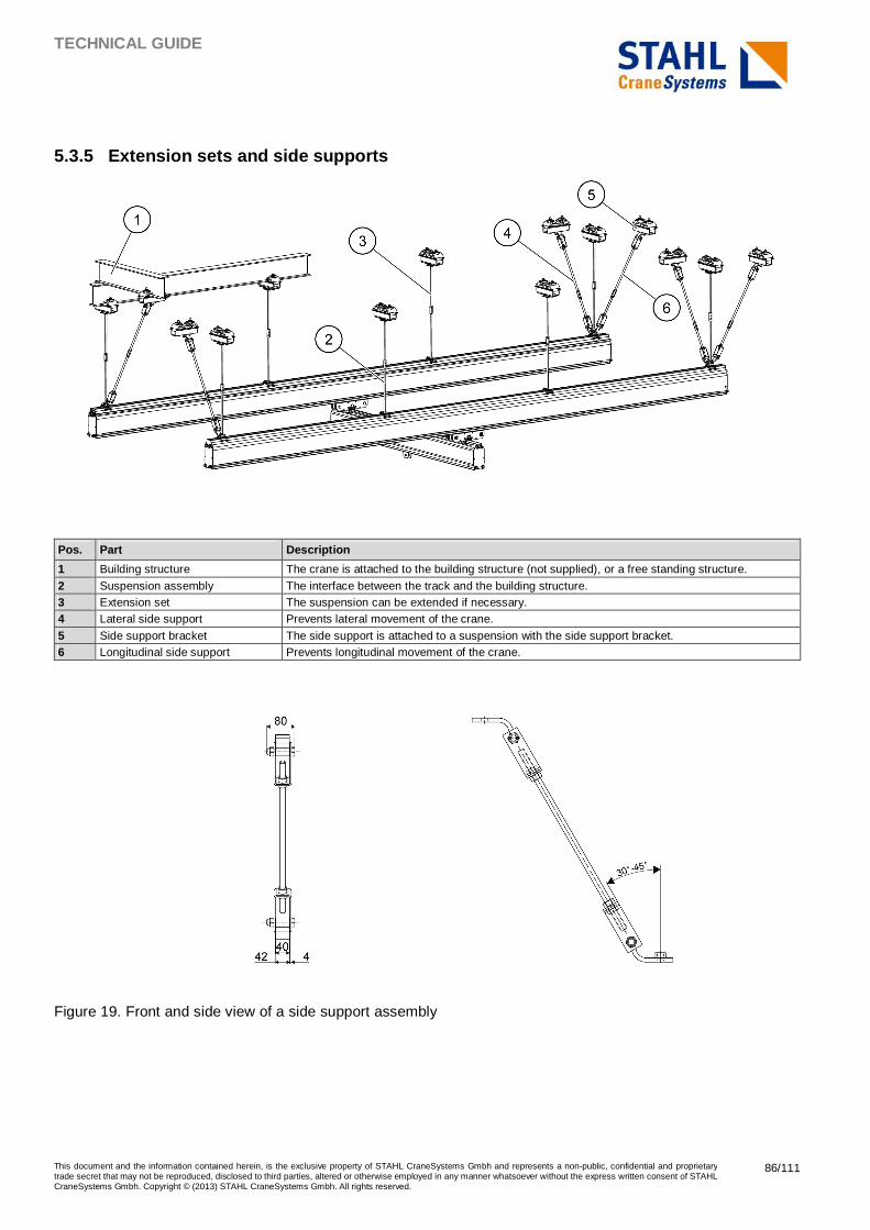
TECHNICAL GUIDE
This document and the information contained herein, is the exclusive property of STAHL CraneSystems Gmbh and represents a non-public, confidential and proprietary trade secret that may not be reproduced, disclosed to third parties, altered or otherwise employed in any manner whatsoever without the express written consent of STAHL CraneSystems Gmbh. Copyright © (2013) STAHL CraneSystems Gmbh. All rights reserved.
86/111
5.3.5 Extension sets and side supports
Pos. Part Description
1 Building structure The crane is attached to the building structure (not supplied), or a free standing structure.
2 Suspension assembly The interface between the track and the building structure. 3 Extension set The suspension can be extended if necessary. 4 Lateral side support Prevents lateral movement of the crane.
5 Side support bracket The side support is attached to a suspension with the side support bracket. 6 Longitudinal side support Prevents longitudinal movement of the crane.
Figure 19. Front and side view of a side support assembly
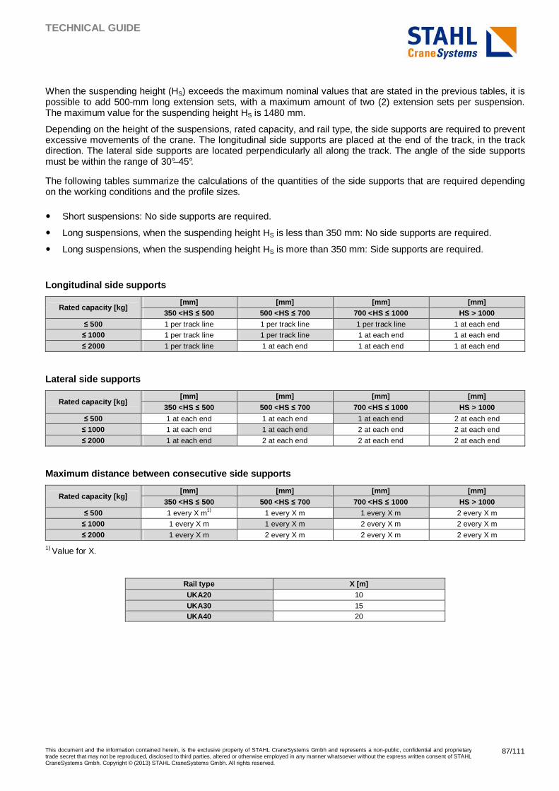
TECHNICAL GUIDE
This document and the information contained herein, is the exclusive property of STAHL CraneSystems Gmbh and represents a non-public, confidential and proprietary trade secret that may not be reproduced, disclosed to third parties, altered or otherwise employed in any manner whatsoever without the express written consent of STAHL CraneSystems Gmbh. Copyright © (2013) STAHL CraneSystems Gmbh. All rights reserved.
87/111
When the suspending height (HS) exceeds the maximum nominal values that are stated in the previous tables, it is possible to add 500-mm long extension sets, with a maximum amount of two (2) extension sets per suspension. The maximum value for the suspending height HS is 1480 mm.
Depending on the height of the suspensions, rated capacity, and rail type, the side supports are required to prevent excessive movements of the crane. The longitudinal side supports are placed at the end of the track, in the track direction. The lateral side supports are located perpendicularly all along the track. The angle of the side supports must be within the range of 30°–45°.
The following tables summarize the calculations of the quantities of the side supports that are required depending on the working conditions and the profile sizes.
� Short suspensions: No side supports are required.
� Long suspensions, when the suspending height HS is less than 350 mm: No side supports are required.
� Long suspensions, when the suspending height HS is more than 350 mm: Side supports are required.
Longitudinal side supports
Rated capacity [kg] [mm] [mm] [mm] [mm]
350 <HS ≤ 500 500 <HS ≤ 700 700 <HS ≤ 1000 HS > 1000 ≤ 500 1 per track line 1 per track line 1 per track line 1 at each end
≤ 1000 1 per track line 1 per track line 1 at each end 1 at each end
≤ 2000 1 per track line 1 at each end 1 at each end 1 at each end
Lateral side supports
Rated capacity [kg] [mm] [mm] [mm] [mm]
350 <HS ≤ 500 500 <HS ≤ 700 700 <HS ≤ 1000 HS > 1000
≤ 500 1 at each end 1 at each end 1 at each end 2 at each end
≤ 1000 1 at each end 1 at each end 2 at each end 2 at each end
≤ 2000 1 at each end 2 at each end 2 at each end 2 at each end
Maximum distance between consecutive side supports
Rated capacity [kg] [mm] [mm] [mm] [mm]
350 <HS ≤ 500 500 <HS ≤ 700 700 <HS ≤ 1000 HS > 1000 ≤ 500 1 every X m1) 1 every X m 1 every X m 2 every X m
≤ 1000 1 every X m 1 every X m 2 every X m 2 every X m
≤ 2000 1 every X m 2 every X m 2 every X m 2 every X m
1) Value for X.
Rail type X [m] UKA20 10
UKA30 15 UKA40 20
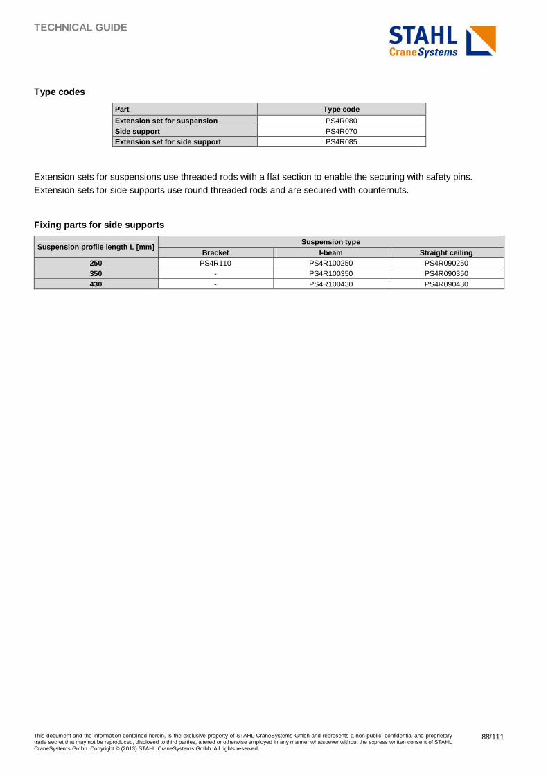
TECHNICAL GUIDE
This document and the information contained herein, is the exclusive property of STAHL CraneSystems Gmbh and represents a non-public, confidential and proprietary trade secret that may not be reproduced, disclosed to third parties, altered or otherwise employed in any manner whatsoever without the express written consent of STAHL CraneSystems Gmbh. Copyright © (2013) STAHL CraneSystems Gmbh. All rights reserved.
88/111
Type codes
Part Type code
Extension set for suspension PS4R080
Side support PS4R070 Extension set for side support PS4R085
Extension sets for suspensions use threaded rods with a flat section to enable the securing with safety pins. Extension sets for side supports use round threaded rods and are secured with counternuts.
Fixing parts for side supports
Suspension profile length L [mm] Suspension type
Bracket I-beam Straight ceiling 250 PS4R110 PS4R100250 PS4R090250 350 - PS4R100350 PS4R090350
430 - PS4R100430 PS4R090430
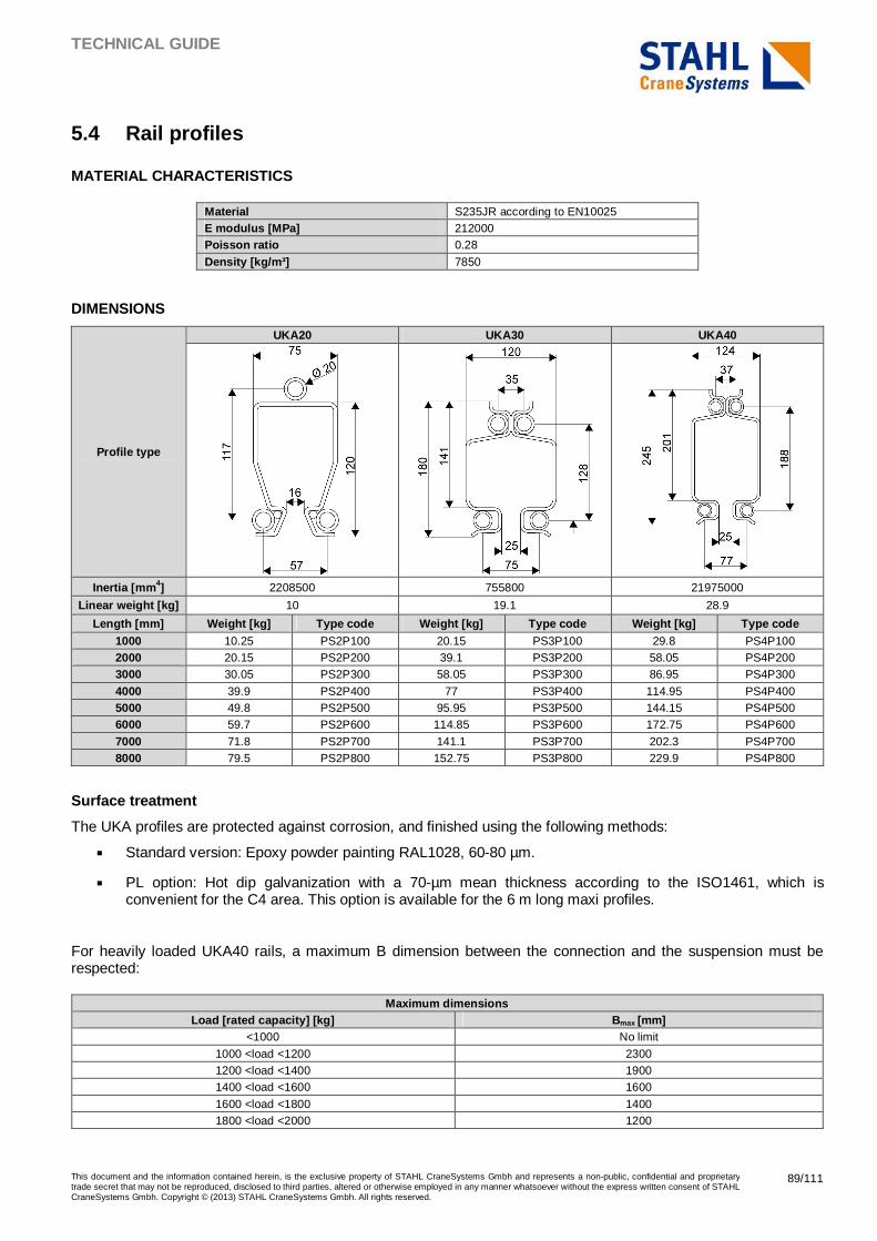
TECHNICAL GUIDE
This document and the information contained herein, is the exclusive property of STAHL CraneSystems Gmbh and represents a non-public, confidential and proprietary trade secret that may not be reproduced, disclosed to third parties, altered or otherwise employed in any manner whatsoever without the express written consent of STAHL CraneSystems Gmbh. Copyright © (2013) STAHL CraneSystems Gmbh. All rights reserved.
89/111
5.4 Rail profiles
MATERIAL CHARACTERISTICS
Material S235JR according to EN10025 E modulus [MPa] 212000 Poisson ratio 0.28
Density [kg/m³] 7850
DIMENSIONS
Profile type
UKA20 UKA30 UKA40
Inertia [mm 4] 2208500 755800 21975000
Linear weight [kg] 10 19.1 28.9
Length [mm] Weight [kg] Type code Weight [kg] Type code Weight [kg] Type code 1000 10.25 PS2P100 20.15 PS3P100 29.8 PS4P100 2000 20.15 PS2P200 39.1 PS3P200 58.05 PS4P200 3000 30.05 PS2P300 58.05 PS3P300 86.95 PS4P300
4000 39.9 PS2P400 77 PS3P400 114.95 PS4P400 5000 49.8 PS2P500 95.95 PS3P500 144.15 PS4P500 6000 59.7 PS2P600 114.85 PS3P600 172.75 PS4P600
7000 71.8 PS2P700 141.1 PS3P700 202.3 PS4P700 8000 79.5 PS2P800 152.75 PS3P800 229.9 PS4P800
Surface treatment
The UKA profiles are protected against corrosion, and finished using the following methods:
� Standard version: Epoxy powder painting RAL1028, 60-80 µm.
� PL option: Hot dip galvanization with a 70-µm mean thickness according to the ISO1461, which is convenient for the C4 area. This option is available for the 6 m long maxi profiles.
For heavily loaded UKA40 rails, a maximum B dimension between the connection and the suspension must be respected:
Maximum dimensions Load [rated capacity] [kg] Bmax [mm]
<1000 No limit
1000 <load <1200 2300 1200 <load <1400 1900 1400 <load <1600 1600
1600 <load <1800 1400 1800 <load <2000 1200
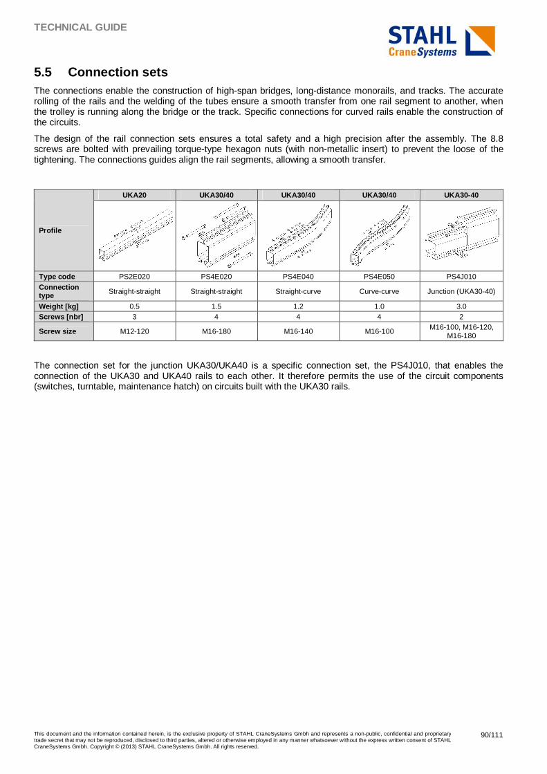
TECHNICAL GUIDE
This document and the information contained herein, is the exclusive property of STAHL CraneSystems Gmbh and represents a non-public, confidential and proprietary trade secret that may not be reproduced, disclosed to third parties, altered or otherwise employed in any manner whatsoever without the express written consent of STAHL CraneSystems Gmbh. Copyright © (2013) STAHL CraneSystems Gmbh. All rights reserved.
90/111
5.5 Connection sets The connections enable the construction of high-span bridges, long-distance monorails, and tracks. The accurate rolling of the rails and the welding of the tubes ensure a smooth transfer from one rail segment to another, when the trolley is running along the bridge or the track. Specific connections for curved rails enable the construction of the circuits.
The design of the rail connection sets ensures a total safety and a high precision after the assembly. The 8.8 screws are bolted with prevailing torque-type hexagon nuts (with non-metallic insert) to prevent the loose of the tightening. The connections guides align the rail segments, allowing a smooth transfer.
Profile
UKA20 UKA30/40 UKA30/40 UKA30/40 UKA30-40
Type code PS2E020 PS4E020 PS4E040 PS4E050 PS4J010
Connection type Straight-straight Straight-straight Straight-curve Curve-curve Junction (UKA30-40)
Weight [kg] 0.5 1.5 1.2 1.0 3.0 Screws [nbr] 3 4 4 4 2
Screw size M12-120 M16-180 M16-140 M16-100 M16-100, M16-120, M16-180
The connection set for the junction UKA30/UKA40 is a specific connection set, the PS4J010, that enables the connection of the UKA30 and UKA40 rails to each other. It therefore permits the use of the circuit components (switches, turntable, maintenance hatch) on circuits built with the UKA30 rails.
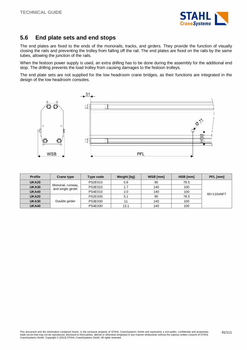
TECHNICAL GUIDE
This document and the information contained herein, is the exclusive property of STAHL CraneSystems Gmbh and represents a non-public, confidential and proprietary trade secret that may not be reproduced, disclosed to third parties, altered or otherwise employed in any manner whatsoever without the express written consent of STAHL CraneSystems Gmbh. Copyright © (2013) STAHL CraneSystems Gmbh. All rights reserved.
91/111
5.6 End plate sets and end stops The end plates are fixed to the ends of the monorails, tracks, and girders. They provide the function of visually closing the rails and preventing the trolley from falling off the rail. The end plates are fixed on the rails by the same tubes, allowing the junction of the rails.
When the festoon power supply is used, an extra drilling has to be done during the assembly for the additional end stop. The drilling prevents the load trolley from causing damages to the festoon trolleys.
The end plate sets are not supplied for the low headroom crane bridges, as their functions are integrated in the design of the low headroom consoles.
Profile Crane type Type code Weight [kg] WSB [mm] HSB [mm] PFL [mm]
UKA20 Monorail, runway, and single girder
PS2E010 0.6 90 78.5
60+110xNFT
UKA30 PS3E010 1.7 140 100 UKA40 PS4E010 2.0 140 100 UKA20
Double girder PS2E030 5.1 90 78.5
UKA30 PS3E030 11 140 100 UKA40 PS4E030 13.1 140 100
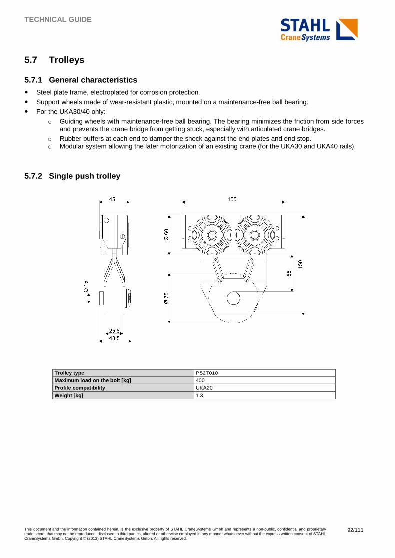
TECHNICAL GUIDE
This document and the information contained herein, is the exclusive property of STAHL CraneSystems Gmbh and represents a non-public, confidential and proprietary trade secret that may not be reproduced, disclosed to third parties, altered or otherwise employed in any manner whatsoever without the express written consent of STAHL CraneSystems Gmbh. Copyright © (2013) STAHL CraneSystems Gmbh. All rights reserved.
92/111
5.7 Trolleys
5.7.1 General characteristics
� Steel plate frame, electroplated for corrosion protection.
� Support wheels made of wear-resistant plastic, mounted on a maintenance-free ball bearing. � For the UKA30/40 only:
o Guiding wheels with maintenance-free ball bearing. The bearing minimizes the friction from side forces and prevents the crane bridge from getting stuck, especially with articulated crane bridges.
o Rubber buffers at each end to damper the shock against the end plates and end stop. o Modular system allowing the later motorization of an existing crane (for the UKA30 and UKA40 rails).
5.7.2 Single push trolley
Trolley type PS2T010 Maximum load on the bolt [kg] 400 Profile compatibility UKA20
Weight [kg] 1.3
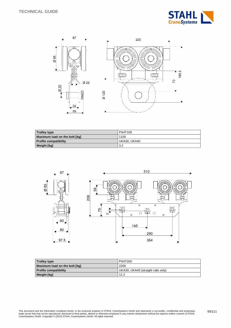
TECHNICAL GUIDE
This document and the information contained herein, is the exclusive property of STAHL CraneSystems Gmbh and represents a non-public, confidential and proprietary trade secret that may not be reproduced, disclosed to third parties, altered or otherwise employed in any manner whatsoever without the express written consent of STAHL CraneSystems Gmbh. Copyright © (2013) STAHL CraneSystems Gmbh. All rights reserved.
93/111
Trolley type PS4T100
Maximum load on the bolt [kg] 1100 Profile compatibility UKA30, UKA40 Weight [kg] 3.2
Trolley type PS4T200
Maximum load on the bolt [kg] 2200 Profile compatibility UKA30, UKA40 (straight rails only) Weight [kg] 12.2
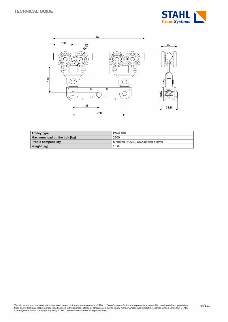
TECHNICAL GUIDE
This document and the information contained herein, is the exclusive property of STAHL CraneSystems Gmbh and represents a non-public, confidential and proprietary trade secret that may not be reproduced, disclosed to third parties, altered or otherwise employed in any manner whatsoever without the express written consent of STAHL CraneSystems Gmbh. Copyright © (2013) STAHL CraneSystems Gmbh. All rights reserved.
94/111
Trolley type PS4T400 Maximum load on the bolt [kg] 2200
Profile compatibility Monorail UKA30, UKA40 with curves Weight [kg] 15.0
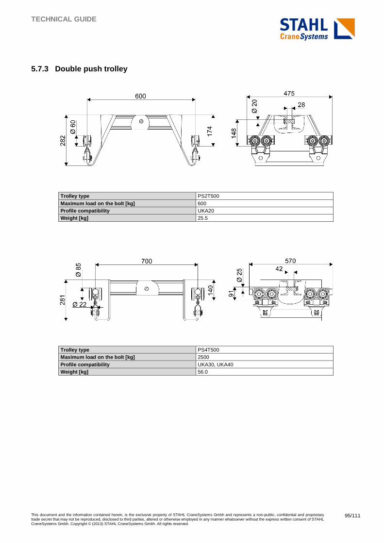
TECHNICAL GUIDE
This document and the information contained herein, is the exclusive property of STAHL CraneSystems Gmbh and represents a non-public, confidential and proprietary trade secret that may not be reproduced, disclosed to third parties, altered or otherwise employed in any manner whatsoever without the express written consent of STAHL CraneSystems Gmbh. Copyright © (2013) STAHL CraneSystems Gmbh. All rights reserved.
95/111
5.7.3 Double push trolley
Trolley type PS2T500
Maximum load on the bolt [kg] 600 Profile compatibility UKA20 Weight [kg] 25.5
Trolley type PS4T500 Maximum load on the bolt [kg] 2500
Profile compatibility UKA30, UKA40 Weight [kg] 56.0
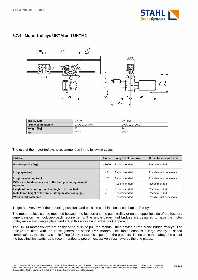
TECHNICAL GUIDE
This document and the information contained herein, is the exclusive property of STAHL CraneSystems Gmbh and represents a non-public, confidential and proprietary trade secret that may not be reproduced, disclosed to third parties, altered or otherwise employed in any manner whatsoever without the express written consent of STAHL CraneSystems Gmbh. Copyright © (2013) STAHL CraneSystems Gmbh. All rights reserved.
96/111
5.7.4 Motor trolleys UKTM and UKTM2
Trolley type UKTM UKTM2
Profile compatibility UKA30, UKA40 UKA30, UKA40 Weight [kg] 43 24
HM 257.5 272.5
The use of the motor trolleys is recommended in the following cases:
Criteria Units Long travel motorized Cross travel motorized
Rated capacity [kg] > 1000 Recommended Recommended
Long span [m] > 6 Recommended Possible, not necessary
Long travel along track > 20 Recommended Possible, not necessary
Difficult or hindered access to the load preventing manual operation - Recommended Recommended
Height of hook during travel too high to be reached - Recommended Recommended
Installation height of the crane (lifting device tr olley) [m] > 5 Recommended Recommended
Work in outreach area - Recommended Possible, not necessary
To get an overview of the mounting positions and possible combinations, see chapter Trolleys.
The motor trolleys can be mounted between the festoon and the push trolley or on the opposite side of the festoon, depending on the hook approach requirements. The single girder rigid bridges are designed to have the motor trolley inside the triangle plate, and are in this way saving in the hook approach.
The UKTM motor trolleys are designed to push or pull the manual lifting device or the crane bridge trolleys. The trolleys are fitted with the latest generation of the TMK motors. This motor enables a large variety of speed combinations, thanks to a simple fitting (dual* or stepless speed) to the products. To increase the safety, the use of the traveling limit switches is recommended to prevent excessive stress towards the end plates.
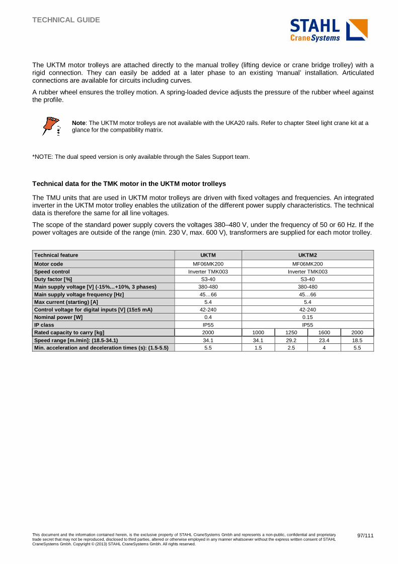
TECHNICAL GUIDE
This document and the information contained herein, is the exclusive property of STAHL CraneSystems Gmbh and represents a non-public, confidential and proprietary trade secret that may not be reproduced, disclosed to third parties, altered or otherwise employed in any manner whatsoever without the express written consent of STAHL CraneSystems Gmbh. Copyright © (2013) STAHL CraneSystems Gmbh. All rights reserved.
97/111
The UKTM motor trolleys are attached directly to the manual trolley (lifting device or crane bridge trolley) with a rigid connection. They can easily be added at a later phase to an existing ‘manual’ installation. Articulated connections are available for circuits including curves.
A rubber wheel ensures the trolley motion. A spring-loaded device adjusts the pressure of the rubber wheel against the profile.
Note : The UKTM motor trolleys are not available with the UKA20 rails. Refer to chapter Steel light crane kit at a glance for the compatibility matrix.
*NOTE: The dual speed version is only available through the Sales Support team.
Technical data for the TMK motor in the UKTM motor trolleys
The TMU units that are used in UKTM motor trolleys are driven with fixed voltages and frequencies. An integrated inverter in the UKTM motor trolley enables the utilization of the different power supply characteristics. The technical data is therefore the same for all line voltages.
The scope of the standard power supply covers the voltages 380–480 V, under the frequency of 50 or 60 Hz. If the power voltages are outside of the range (min. 230 V, max. 600 V), transformers are supplied for each motor trolley.
Technical feature UKTM UKTM2
Motor code MF06MK200 MF06MK200
Speed control Inverter TMK003 Inverter TMK003 Duty factor [%] S3-40 S3-40 Main supply voltage [V] (-15%…+10%, 3 phases) 380-480 380-480
Main supply voltage frequency [Hz] 45…66 45…66 Max current (starting) [A] 5.4 5.4 Control voltage for digital inputs [V] (15±5 mA) 42-240 42-240 Nominal power [W] 0.4 0.15
IP class IP55 IP55 Rated capacity to carry [kg] 2000 1000 1250 1600 2000
Speed range [m./min]: (18.5-34.1) 34.1 34.1 29.2 23.4 18.5 Min. acceleration and deceleration times (s): (1.5- 5.5) 5.5 1.5 2.5 4 5.5
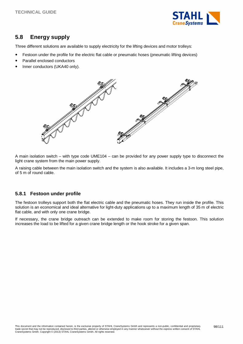
TECHNICAL GUIDE
This document and the information contained herein, is the exclusive property of STAHL CraneSystems Gmbh and represents a non-public, confidential and proprietary trade secret that may not be reproduced, disclosed to third parties, altered or otherwise employed in any manner whatsoever without the express written consent of STAHL CraneSystems Gmbh. Copyright © (2013) STAHL CraneSystems Gmbh. All rights reserved.
98/111
5.8 Energy supply
Three different solutions are available to supply electricity for the lifting devices and motor trolleys:
� Festoon under the profile for the electric flat cable or pneumatic hoses (pneumatic lifting devices)
� Parallel enclosed conductors � Inner conductors (UKA40 only).
A main isolation switch – with type code UME104 – can be provided for any power supply type to disconnect the light crane system from the main power supply.
A raising cable between the main isolation switch and the system is also available. It includes a 3-m long steel pipe, of 5 m of round cable.
5.8.1 Festoon under profile
The festoon trolleys support both the flat electric cable and the pneumatic hoses. They run inside the profile. This solution is an economical and ideal alternative for light-duty applications up to a maximum length of 35 m of electric flat cable, and with only one crane bridge.
If necessary, the crane bridge outreach can be extended to make room for storing the festoon. This solution increases the load to be lifted for a given crane bridge length or the hook stroke for a given span.
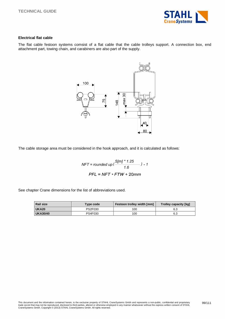
TECHNICAL GUIDE
This document and the information contained herein, is the exclusive property of STAHL CraneSystems Gmbh and represents a non-public, confidential and proprietary trade secret that may not be reproduced, disclosed to third parties, altered or otherwise employed in any manner whatsoever without the express written consent of STAHL CraneSystems Gmbh. Copyright © (2013) STAHL CraneSystems Gmbh. All rights reserved.
99/111
Electrical flat cable
The flat cable festoon systems comsist of a flat cable that the cable trolleys support. A connection box, end attachment part, towing chain, and carabiners are also part of the supply.
The cable storage area must be considered in the hook approach, and it is calculated as follows:
See chapter Crane dimensions for the list of abbreviations used.
Rail size Type code Festoon trolley width [mm] Trolley capacity [kg]
UKA20 PS2F030 100 6.3
UKA30/40 PS4F030 100 6.3
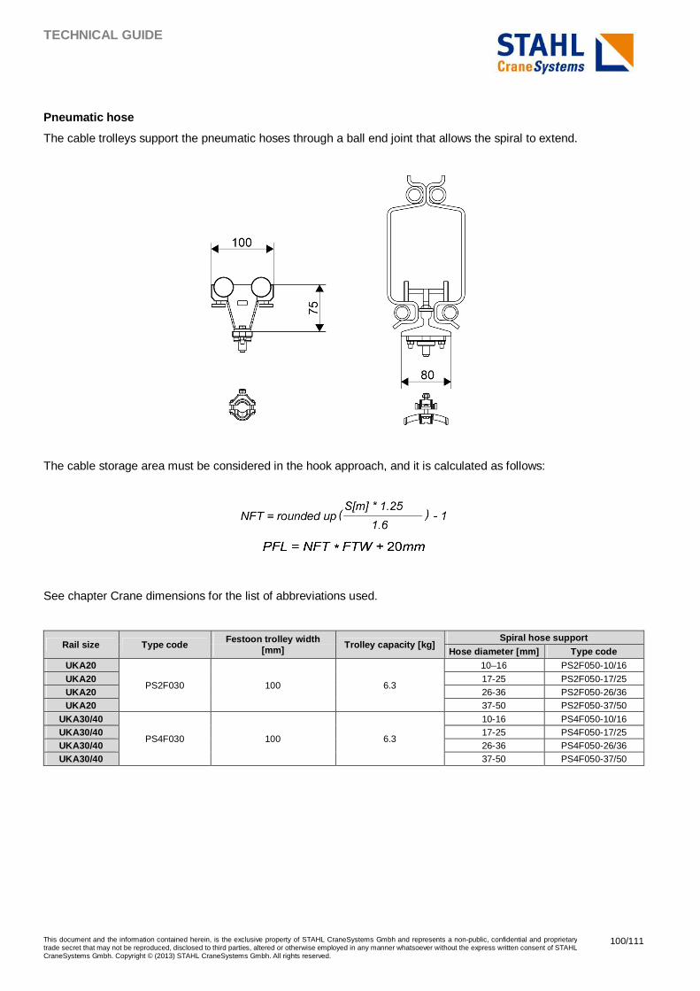
TECHNICAL GUIDE
This document and the information contained herein, is the exclusive property of STAHL CraneSystems Gmbh and represents a non-public, confidential and proprietary trade secret that may not be reproduced, disclosed to third parties, altered or otherwise employed in any manner whatsoever without the express written consent of STAHL CraneSystems Gmbh. Copyright © (2013) STAHL CraneSystems Gmbh. All rights reserved.
100/111
Pneumatic hose
The cable trolleys support the pneumatic hoses through a ball end joint that allows the spiral to extend.
The cable storage area must be considered in the hook approach, and it is calculated as follows:
See chapter Crane dimensions for the list of abbreviations used.
Rail size Type code Festoon trolley width
[mm] Trolley capacity [kg] Spiral hose support
Hose diameter [mm] Type code UKA20
PS2F030 100 6.3
10–16 PS2F050-10/16
UKA20 17-25 PS2F050-17/25 UKA20 26-36 PS2F050-26/36 UKA20 37-50 PS2F050-37/50
UKA30/40
PS4F030 100 6.3
10-16 PS4F050-10/16 UKA30/40 17-25 PS4F050-17/25 UKA30/40 26-36 PS4F050-26/36 UKA30/40 37-50 PS4F050-37/50
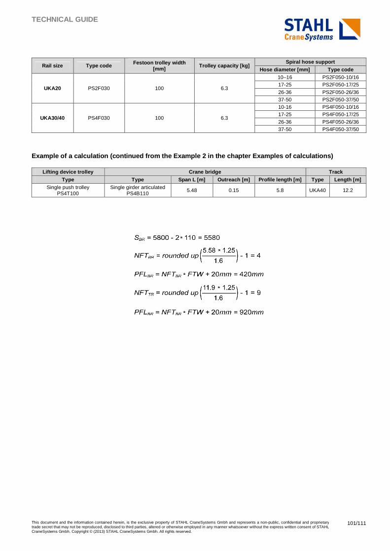
TECHNICAL GUIDE
This document and the information contained herein, is the exclusive property of STAHL CraneSystems Gmbh and represents a non-public, confidential and proprietary trade secret that may not be reproduced, disclosed to third parties, altered or otherwise employed in any manner whatsoever without the express written consent of STAHL CraneSystems Gmbh. Copyright © (2013) STAHL CraneSystems Gmbh. All rights reserved.
101/111
Rail size Type code Festoon trolley width [mm]
Trolley capacity [kg] Spiral hose support
Hose diameter [mm] Type code
UKA20 PS2F030 100 6.3
10–16 PS2F050-10/16 17-25 PS2F050-17/25
26-36 PS2F050-26/36 37-50 PS2F050-37/50
UKA30/40 PS4F030 100 6.3
10-16 PS4F050-10/16 17-25 PS4F050-17/25
26-36 PS4F050-26/36 37-50 PS4F050-37/50
Example of a calculation (continued from the Exampl e 2 in the chapter Examples of calculations)
Lifting device trolley Crane bridge Track Type Type Span L [m] Outreach [m] Profile length [m] Type Length [m]
Single push trolley PS4T100
Single girder articulated PS4B110
5.48 0.15 5.8 UKA40 12.2
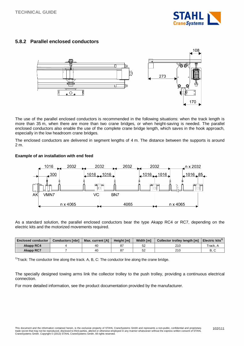
TECHNICAL GUIDE
This document and the information contained herein, is the exclusive property of STAHL CraneSystems Gmbh and represents a non-public, confidential and proprietary trade secret that may not be reproduced, disclosed to third parties, altered or otherwise employed in any manner whatsoever without the express written consent of STAHL CraneSystems Gmbh. Copyright © (2013) STAHL CraneSystems Gmbh. All rights reserved.
102/111
5.8.2 Parallel enclosed conductors
The use of the parallel enclosed conductors is recommended in the following situations: when the track length is more than 35 m, when there are more than two crane bridges, or when height-saving is needed. The parallel enclosed conductors also enable the use of the complete crane bridge length, which saves in the hook approach, especially in the low headroom crane bridges.
The enclosed conductors are delivered in segment lengths of 4 m. The distance between the supports is around 2 m.
Example of an installation with end feed
As a standard solution, the parallel enclosed conductors bear the type Akapp RC4 or RC7, depending on the electric kits and the motorized movements required.
Enclosed conductor Conductors [nbr] Max. current [A] Height [m] Width [m] Collector trolley length [m] Electric kits 1)
Akapp RC4 4 40 87 52 210 Track, A
Akapp RC7 7 40 87 52 210 B, C
1)Track: The conductor line along the track. A, B, C: The conductor line along the crane bridge.
The specially designed towing arms link the collector trolley to the push trolley, providing a continuous electrical connection.
For more detailed information, see the product documentation provided by the manufacturer.
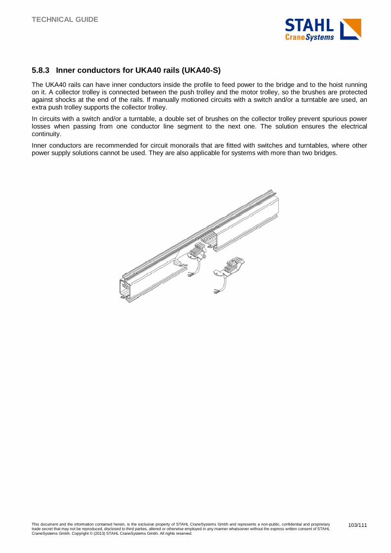
TECHNICAL GUIDE
This document and the information contained herein, is the exclusive property of STAHL CraneSystems Gmbh and represents a non-public, confidential and proprietary trade secret that may not be reproduced, disclosed to third parties, altered or otherwise employed in any manner whatsoever without the express written consent of STAHL CraneSystems Gmbh. Copyright © (2013) STAHL CraneSystems Gmbh. All rights reserved.
103/111
5.8.3 Inner conductors for UKA40 rails (UKA40-S)
The UKA40 rails can have inner conductors inside the profile to feed power to the bridge and to the hoist running on it. A collector trolley is connected between the push trolley and the motor trolley, so the brushes are protected against shocks at the end of the rails. If manually motioned circuits with a switch and/or a turntable are used, an extra push trolley supports the collector trolley.
In circuits with a switch and/or a turntable, a double set of brushes on the collector trolley prevent spurious power losses when passing from one conductor line segment to the next one. The solution ensures the electrical continuity.
Inner conductors are recommended for circuit monorails that are fitted with switches and turntables, where other power supply solutions cannot be used. They are also applicable for systems with more than two bridges.
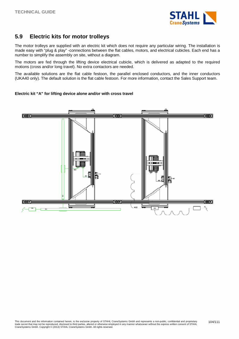
TECHNICAL GUIDE
This document and the information contained herein, is the exclusive property of STAHL CraneSystems Gmbh and represents a non-public, confidential and proprietary trade secret that may not be reproduced, disclosed to third parties, altered or otherwise employed in any manner whatsoever without the express written consent of STAHL CraneSystems Gmbh. Copyright © (2013) STAHL CraneSystems Gmbh. All rights reserved.
104/111
5.9 Electric kits for motor trolleys
The motor trolleys are supplied with an electric kit which does not require any particular wiring. The installation is made easy with “plug & play” -connections between the flat cables, motors, and electrical cubicles. Each end has a number to simplify the assembly on site, without a diagram.
The motors are fed through the lifting device electrical cubicle, which is delivered as adapted to the required motions (cross and/or long travel). No extra contactors are needed.
The available solutions are the flat cable festoon, the parallel enclosed conductors, and the inner conductors (UKA40 only). The default solution is the flat cable festoon. For more information, contact the Sales Support team.
Electric kit “A” for lifting device alone and/or wi th cross travel
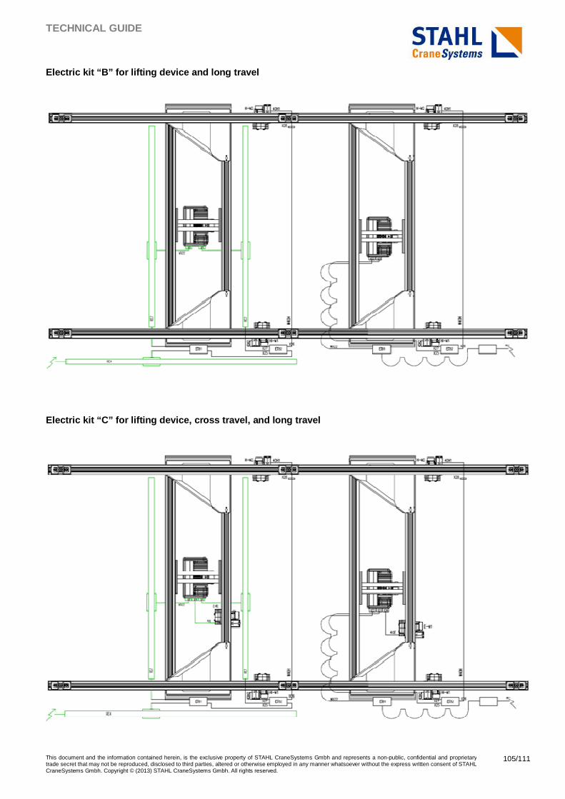
TECHNICAL GUIDE
This document and the information contained herein, is the exclusive property of STAHL CraneSystems Gmbh and represents a non-public, confidential and proprietary trade secret that may not be reproduced, disclosed to third parties, altered or otherwise employed in any manner whatsoever without the express written consent of STAHL CraneSystems Gmbh. Copyright © (2013) STAHL CraneSystems Gmbh. All rights reserved.
105/111
Electric kit “B” for lifting device and long travel
Electric kit “C” for lifting device, cross travel, and long travel
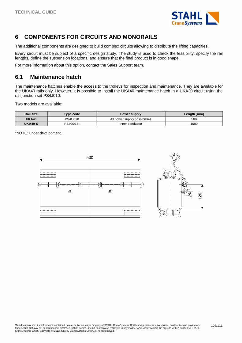
TECHNICAL GUIDE
This document and the information contained herein, is the exclusive property of STAHL CraneSystems Gmbh and represents a non-public, confidential and proprietary trade secret that may not be reproduced, disclosed to third parties, altered or otherwise employed in any manner whatsoever without the express written consent of STAHL CraneSystems Gmbh. Copyright © (2013) STAHL CraneSystems Gmbh. All rights reserved.
106/111
6 COMPONENTS FOR CIRCUITS AND MONORAILS
The additional components are designed to build complex circuits allowing to distribute the lifting capacities.
Every circuit must be subject of a specific design study. The study is used to check the feasibility, specify the rail lengths, define the suspension locations, and ensure that the final product is in good shape.
For more information about this option, contact the Sales Support team.
6.1 Maintenance hatch
The maintenance hatches enable the access to the trolleys for inspection and maintenance. They are available for the UKA40 rails only. However, it is possible to install the UKA40 maintenance hatch in a UKA30 circuit using the rail junction set PS4J010.
Two models are available:
Rail size Type code Power supply Length [mm]
UKA40 PS4O010 All power supply possibilities 500 UKA40-S PS4O015* Inner conductor 1000
*NOTE: Under development.
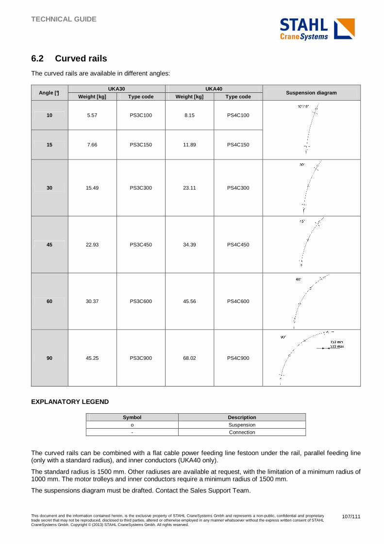
TECHNICAL GUIDE
This document and the information contained herein, is the exclusive property of STAHL CraneSystems Gmbh and represents a non-public, confidential and proprietary trade secret that may not be reproduced, disclosed to third parties, altered or otherwise employed in any manner whatsoever without the express written consent of STAHL CraneSystems Gmbh. Copyright © (2013) STAHL CraneSystems Gmbh. All rights reserved.
107/111
6.2 Curved rails
The curved rails are available in different angles:
Angle [°] UKA30 UKA40
Suspension diagram Weight [kg] Type code Weight [kg] Type code
10 5.57 PS3C100 8.15 PS4C100
15 7.66 PS3C150 11.89 PS4C150
30 15.49 PS3C300 23.11 PS4C300
45 22.93 PS3C450 34.39 PS4C450
60 30.37 PS3C600 45.56 PS4C600
90 45.25 PS3C900 68.02 PS4C900
EXPLANATORY LEGEND
Symbol Description o Suspension
- Connection
The curved rails can be combined with a flat cable power feeding line festoon under the rail, parallel feeding line (only with a standard radius), and inner conductors (UKA40 only).
The standard radius is 1500 mm. Other radiuses are available at request, with the limitation of a minimum radius of 1000 mm. The motor trolleys and inner conductors require a minimum radius of 1500 mm.
The suspensions diagram must be drafted. Contact the Sales Support Team.
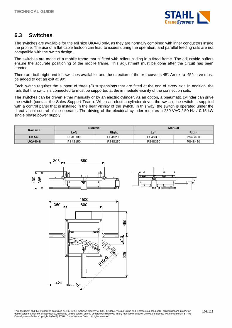
TECHNICAL GUIDE
This document and the information contained herein, is the exclusive property of STAHL CraneSystems Gmbh and represents a non-public, confidential and proprietary trade secret that may not be reproduced, disclosed to third parties, altered or otherwise employed in any manner whatsoever without the express written consent of STAHL CraneSystems Gmbh. Copyright © (2013) STAHL CraneSystems Gmbh. All rights reserved.
108/111
6.3 Switches The switches are available for the rail size UKA40 only, as they are normally combined with inner conductors inside the profile. The use of a flat cable festoon can lead to issues during the operation, and parallel feeding rails are not compatible with the switch design.
The switches are made of a mobile frame that is fitted with rollers sliding in a fixed frame. The adjustable buffers ensure the accurate positioning of the mobile frame. This adjustment must be done after the circuit has been erected.
There are both right and left switches available, and the direction of the exit curve is 45°. An extra 45° curve must be added to get an exit at 90°.
Each switch requires the support of three (3) suspensions that are fitted at the end of every exit. In addition, the rails that the switch is connected to must be supported at the immediate vicinity of the connection sets.
The switches can be driven either manually or by an electric cylinder. As an option, a pneumatic cylinder can drive the switch (contact the Sales Support Team). When an electric cylinder drives the switch, the switch is supplied with a control panel that is installed in the near vicinity of the switch. In this way, the switch is operated under the direct visual control of the operator. The driving of the electrical cylinder requires a 230-VAC / 50-Hz / 0.15-kW single phase power supply.
Rail size Electric Manual
Left Right Left Right UKA40 PS4S100 PS4S200 PS4S300 PS4S400
UKA40-S PS4S150 PS4S250 PS4S350 PS4S450
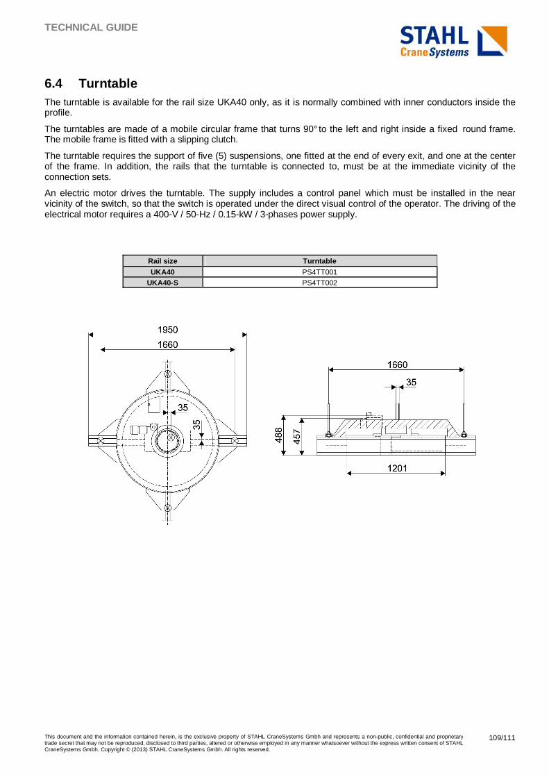
TECHNICAL GUIDE
This document and the information contained herein, is the exclusive property of STAHL CraneSystems Gmbh and represents a non-public, confidential and proprietary trade secret that may not be reproduced, disclosed to third parties, altered or otherwise employed in any manner whatsoever without the express written consent of STAHL CraneSystems Gmbh. Copyright © (2013) STAHL CraneSystems Gmbh. All rights reserved.
109/111
6.4 Turntable The turntable is available for the rail size UKA40 only, as it is normally combined with inner conductors inside the profile.
The turntables are made of a mobile circular frame that turns 90° to the left and right inside a fixed round frame. The mobile frame is fitted with a slipping clutch.
The turntable requires the support of five (5) suspensions, one fitted at the end of every exit, and one at the center of the frame. In addition, the rails that the turntable is connected to, must be at the immediate vicinity of the connection sets.
An electric motor drives the turntable. The supply includes a control panel which must be installed in the near vicinity of the switch, so that the switch is operated under the direct visual control of the operator. The driving of the electrical motor requires a 400-V / 50-Hz / 0.15-kW / 3-phases power supply.
Rail size Turntable
UKA40 PS4TT001
UKA40-S PS4TT002
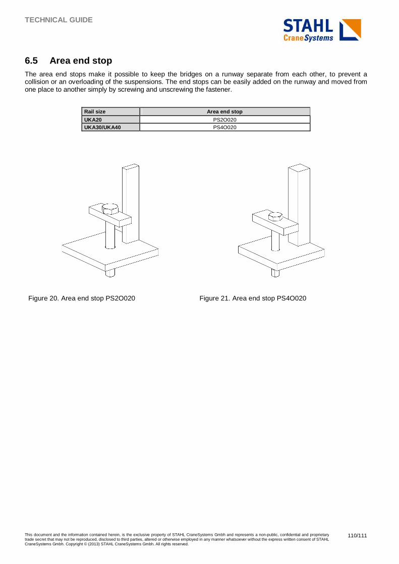
TECHNICAL GUIDE
This document and the information contained herein, is the exclusive property of STAHL CraneSystems Gmbh and represents a non-public, confidential and proprietary trade secret that may not be reproduced, disclosed to third parties, altered or otherwise employed in any manner whatsoever without the express written consent of STAHL CraneSystems Gmbh. Copyright © (2013) STAHL CraneSystems Gmbh. All rights reserved.
110/111
6.5 Area end stop The area end stops make it possible to keep the bridges on a runway separate from each other, to prevent a collision or an overloading of the suspensions. The end stops can be easily added on the runway and moved from one place to another simply by screwing and unscrewing the fastener.
Rail size Area end stop
UKA20 PS2O020 UKA30/UKA40 PS4O020
Figure 20. Area end stop PS2O020 Figure 21. Area end stop PS4O020
TECHNICAL GUIDE
This document and the information contained herein, is the exclusive property of STAHL CraneSystems Gmbh and represents a non-public, confidential and proprietary trade secret that may not be reproduced, disclosed to third parties, altered or otherwise employed in any manner whatsoever without the express written consent of STAHL CraneSystems Gmbh. Copyright © (2013) STAHL CraneSystems Gmbh. All rights reserved.
111/111
6.6 Distance buffer When a minimum distance between the bridges must be respected, but the bridges must be able to cover the widest possible area, it is possible to include a distance buffer between the bridges. This kind of solution may be required for example to prevent a suspension overloading when heavily loaded bridges are used.
� If the distance between the bridges is less than 800 mm, the required number of simple push trolleys is added between the bridges.
� If the distance between the bridges is greater than 800 mm, a hollow profile, that is cut to length, is used to link two simple push trolleys to each other.