Embed Size (px)
Citation preview

PurgEx Z – Purge Indicator
User’s Manual

This page intentionally left blank
Information in this document is subject to change without notice. All terms mentioned in this manual that are known to be trademarks have been appropriately capitalized. R. STAHL, Inc. acknowledges all trademark(s) and the rights of the trademark(s) owned by the company referred to herein.
13259 N. Promenade Blvd. Stafford, TX 77477
Phone: 800-782-4357
Website: www.rstahl.com
Release Date: April 2014
Document Number: DO-10011-S
© Copyright 2014 by R. STAHL, Inc.
All rights reserved
Copyright Notice:
This document contains information proprietary to R. STAHL, Inc. with all rights reserved worldwide. Any reproduction or disclosure of this publication, or any part thereof, to persons other than R. STAHL, Inc. personnel or customers is strictly prohibited, except by written permission of R. STAHL, Inc. Unauthorized use, disclosure, reproduction, or translation of this publication will result in R. STAHL, Inc. exercising maximum possible legal action against all persons and/or organizations involved.
Disclaimer: R. STAHL, Inc. makes every effort to ensure the accuracy and completeness of this manual. However, we cannot be responsible for errors, omissions, or any loss of data as the results of errors or omissions. We therefore make no representations or warranties with respect to the contents hereof. Further, R. STAHL, Inc. reserves the right to revise this publication and to make changes in the content hereof, without obligation to notify any person or organization of such revision or changes.
Revision Record
Rev. Description Date
A Initial Release 12-Aug-02
B Web Site Changes 02-Jan-03
C Add 12 DC Powered Model 23-Mar-03
D Several Revisions 07-Dec-03
E Several Revisions 14-Mar-04
F Several Revisions 29-June-04
G Several Revisions 14-Dec-04
H Several Revisions 27-May-05
I Added Recommended UL Power Supply Requirements 06-Jan-06
J Revised Options and Illustrations 01-Mar-06
K Revised Initial and Maintenance Start Up Procedures 13-Jan-07
L Revised Illustrations 24-Jan-08
M Revisions Per Certification Updates and New Product Offerings 23-Aug-08
N Revisions Per New Purge Gas Inlet Kits Procedures 21-Aug-09
O Several Revisions 11-Nov-09
P Addition of Dust and Amended Installation Instructions 18-Nov-10
Q Removal of PURGEX Y – Purge Indicator from this manual 13-Jun-11
R Addition of Increase Safety Window Kits and UL Certification 17-Jun-13
S Address and Certification Changes 25-Nov-13
T Certification Required Revisions 18-Sep-14
U Added Storage Temperature Range 21-May-15
Shipment Arrival Procedures: This shipment has been thoroughly inspected at the factory prior to its delivery to the carrier. After the shipment is picked up by the carrier, it becomes their responsibility. When the shipment arrives, make certain that it is undamaged and complete.
Patent Notice: Manufactured under United States, Worldwide Patents, and Patents Pending.
Trademark Information: R. STAHL, Inc. and its logo(s) are trademark(s) of R. STAHL, Inc.

Table of ContentsLegal Notices and Revision History Inside front cover
Section 1
How To Use This Manual 1 Safety Considerations 1 Label Definition Table 2 Locating Information 2 General Safety 3 General Precautions 3 Electrical Power 4 System Location 4 Purge Systems 4
Section 2
Specifications 5 Features Table 5 Normal Operating Conditions Table 5 Utility Requirements Table 6 Environmental Conditions Table 6 Model Number Matrix Tables 7
Section 3
Introduction 9 Description 9
Section 4
Installation 13 Mounting 13 Electrical Power Installation 16 Power Source Table 16 Power Connection Table 17 Alarm Signal Installation 17 Alarm Source Table 17
Alarm Connection Table 17
Section 5
Start Up Procedures 18 Initial Start Up 18 Maintenance or Service Shut Down and Start Up Procedure 29
Section 6
Documents 32 Drawing, Flow Diagrams 35 Drawing, Dimensional General Assembly 39 Drawing, Mounting Hole Template 40 Drawing, Wiring Diagram 41
Section 7
Options 42
Section 8
Getting Help 45

Section 1
How to Use This Manual
Safety Considerations:
This chapter includes important information that must be read and understood by all persons installing, using, or maintaining this equipment. While this manual is designed to aid personnel in the correct and safe installation, operation, and maintenance of the systems described. Personnel must consider all actions and procedures for potential hazards or conditions that may not have been anticipated in the written procedures. If a procedure cannot be performed safely, it must not be performed until appropriate actions can be taken to ensure the safety of equipment and personnel. The procedures in this manual are not designed to replace or supersede required or common sense safety practices. All safety warnings listed in any documents applicable to equipment and parts used in or with the system described in this manual must be read and heeded before commencing work on any part of the system.
NOTE: Refer to all ATEX, CSA, IECEx, NEC, NFPA and UL certificates
for any Special Conditions of Use. If the sign “X” is placed after the certificate number, it indicates that the equipment or protective system is subject to special conditions for safe use specified in the schedule of the certificate.
NOTE: Review all material and safety information in this manual and
install in accordance with this document and all other applicable ATEX, CSA, IECEx, NEC, NFPA 496 and UL standards.
WARNING: Failure to follow appropriate safety procedures or
inappropriate use of the equipment described in this manual can lead to injury of personnel or equipment damage.
WARNING – EXPLOSION HAZARD – Do not disconnect
equipment unless power has been removed or the area is known to be non-hazardous.
1
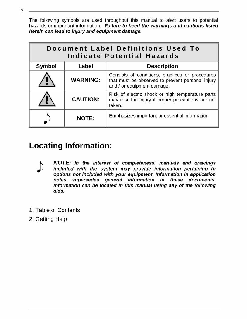
The following symbols are used throughout this manual to alert users to potential hazards or important information. Failure to heed the warnings and cautions listed herein can lead to injury and equipment damage.
D o c u m e n t L a b e l D e f i n i t i o n s U s e d T o I n d i c a t e P o t e n t i a l H a z a r d s
Symbol Label Description
WARNING: Consists of conditions, practices or procedures that must be observed to prevent personal injury and / or equipment damage.
CAUTION: Risk of electric shock or high temperature parts may result in injury if proper precautions are not taken.
NOTE: Emphasizes important or essential information.
Locating Information:
NOTE: In the interest of completeness, manuals and drawings
included with the system may provide information pertaining to options not included with your equipment. Information in application notes supersedes general information in these documents. Information can be located in this manual using any of the following aids.
1. Table of Contents
2. Getting Help
2
General Safety and Operating Information:
This section contains general safety and operating information applicable to electrical equipment installed within hazardous locations. This information must be understood by all persons installing, using, or maintaining the electrical equipment. This information is designed to aid personnel in safe installation, operation, and maintenance of the PURGEX Z – Purge Indicator. It is not designed to replace or limit appropriate safety measures applicable to work performed by personnel. Any additional safety and operating measures that are required must be determined by and followed by personnel performing work on the electrical equipment.
WARNING: Deviation from the specified instruction or procedure
steps can result in injury to personnel, equipment malfunction and / or equipment damage.
WARNING: Return unit to factory for any repairs or replacement of
parts, customer not permitted. This will void all warranties and hazardous area certification(s).
General Precautions: Protective eyewear (glasses with side shields or goggles as appropriate) must be worn when servicing any part of electrical equipment. Hot components should be allowed to cool before servicing if possible. Other appropriate equipment or clothing must be used as required by the type of work performed. All applicable regulations and procedures must be followed for the work performed. Before beginning any work on the equipment, carefully consider all the potential hazards and ensure that appropriate measures are taken to prevent injury to personnel or equipment damage.
CAUTION: Electrical equipment components may be hot even when
power is not applied. Take appropriate precautions to prevent injury from contact with hot items.
CAUTION: Applicable permits must be obtained and appropriate
precautions must be taken to prevent possible injury to personnel or equipment damage when installing or maintaining this equipment.
3
Electrical Power: The PURGEX Z – Purge Indicator uses AC power of 115 or 230 volts and DC power of 12 or 24. The AC power is converted to DC. Appropriate precautions must be taken to prevent sparks that may ignite combustible materials that may be present in the Purge Indicator’s environment. Precautions must also be taken to prevent electrical shock if the electrical equipment’s enclosure being monitored by the PURGEX Z – Purge Indicator is opened. The power to the PURGEX Z – Purge Indicator must be free from noise, surges, sags, and spikes for proper operation of the purge indicator. AC power circuit breakers and wiring must be sized properly for the required current. All wiring installations must meet applicable electrical codes.
System Location: The PURGEX Z – Purge Indicator must not be installed in an area classification for which it is not rated and must be protected from temperature extremes and potentially high vibration. The PURGEX Z – Purge Indicator must be attached securely and appropriately to the wall of the electrical equipment’s enclosure being monitored per the mounting instructions page 13 and mounted in a location to permit adequate viewing of green indicator light and to permit proper purge exhaust venting.
Purge Systems:
NOTE: Electrical equipment may use purging to ensure safe
operation when installed within a hazardous location. The protective gas purge supply must be clean, dry, and free from hydrocarbons or corrosive materials.
NOTE: This devise is a purge / pressurized indicator intended to be
mounted to an enclosure that would need to be fully evaluated to NFPA 496. For correct installation and assembly refer to NFPA 496, 2013 Edition.
WARNING: Substitution of components may impair suitability for
Division 2.
NOTE: This equipment is suitable for use in Class I, Division 2, Group
A, B, C & D, Class II, Division 2, Group F & G, Class III Hazardous Location or unclassified locations.
4
Section 2
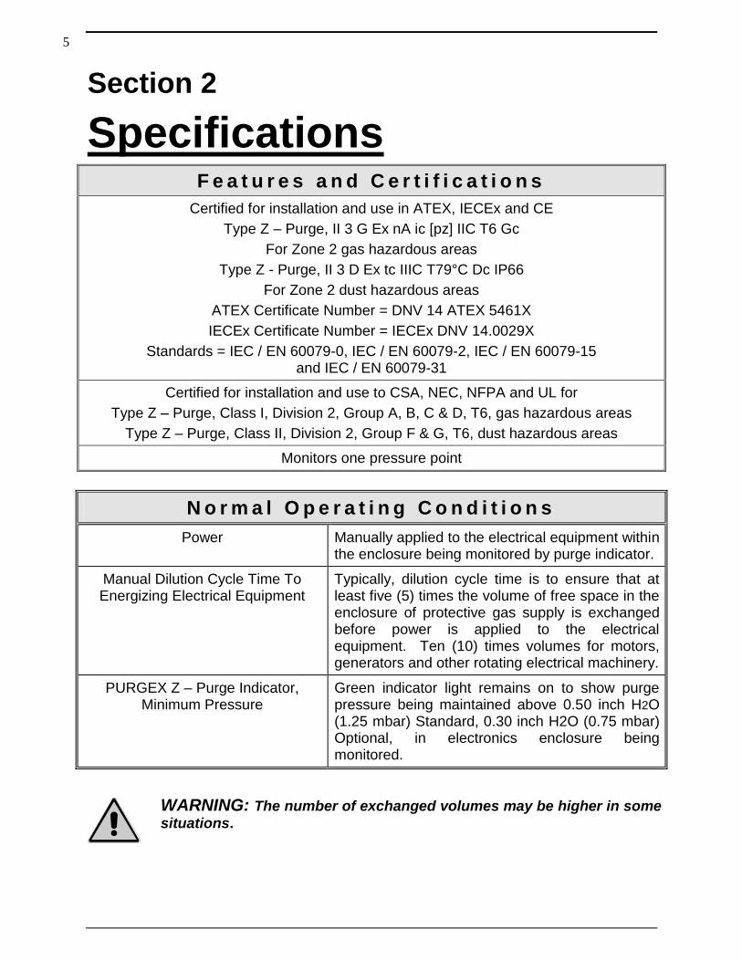
Specifications F e a t u r e s a n d C e r t i f i c a t i o n s
Certified for installation and use in ATEX, IECEx and CE
Type Z – Purge, II 3 G Ex nA ic [pz] IIC T6 Gc
For Zone 2 gas hazardous areas
Type Z - Purge, II 3 D Ex tc IIIC T79°C Dc IP66
For Zone 2 dust hazardous areas
ATEX Certificate Number = DNV 14 ATEX 5461X
IECEx Certificate Number = IECEx DNV 14.0029X
Standards = IEC / EN 60079-0, IEC / EN 60079-2, IEC / EN 60079-15 and IEC / EN 60079-31
Certified for installation and use to CSA, NEC, NFPA and UL for
Type Z – Purge, Class I, Division 2, Group A, B, C & D, T6, gas hazardous areas
Type Z – Purge, Class II, Division 2, Group F & G, T6, dust hazardous areas
Monitors one pressure point
N o r m a l O p e r a t i n g C o n d i t i o n s
Power Manually applied to the electrical equipment within the enclosure being monitored by purge indicator.
Manual Dilution Cycle Time To Energizing Electrical Equipment
Typically, dilution cycle time is to ensure that at least five (5) times the volume of free space in the enclosure of protective gas supply is exchanged before power is applied to the electrical equipment. Ten (10) times volumes for motors, generators and other rotating electrical machinery.
PURGEX Z – Purge Indicator, Minimum Pressure
Green indicator light remains on to show purge pressure being maintained above 0.50 inch H2O (1.25 mbar) Standard, 0.30 inch H2O (0.75 mbar) Optional, in electronics enclosure being monitored.
WARNING: The number of exchanged volumes may be higher in some
situations.
5
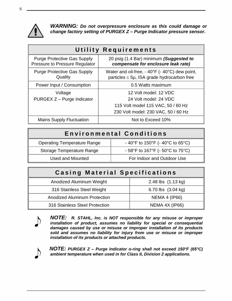
WARNING: Do not overpressure enclosure as this could damage or
change factory setting of PURGEX Z – Purge Indicator pressure sensor.
U t i l i t y R e q u i r e m e n t s
Purge Protective Gas Supply Pressure to Pressure Regulator
20 psig (1.4 Bar) minimum (Suggested to compensate for enclosure leak rate)
Purge Protective Gas Supply Quality
Water and oil-free, - 40°F (- 40°C) dew point,
particles 5µ, ISA grade hydrocarbon free
Power Input / Consumption 0.5 Watts maximum
Voltage
PURGEX Z – Purge Indicator
12 Volt model: 12 VDC
24 Volt model: 24 VDC
115 Volt model 115 VAC, 50 / 60 Hz
230 Volt model: 230 VAC, 50 / 60 Hz
Mains Supply Fluctuation Not to Exceed 10%
E n v i r o n m e n t a l C o n d i t i o n s
Operating Temperature Range - 40°F to 150°F (- 40°C to 65°C)
Storage Temperature Range - 58°F to 167°F (- 50°C to 75°C)
Used and Mounted For Indoor and Outdoor Use
C a s i n g M a t e r i a l S p e c i f i c a t i o n s
Anodized Aluminum Weight 2.48 lbs (1.13 kg)
316 Stainless Steel Weight 6.70 lbs (3.04 kg)
Anodized Aluminum Protection NEMA 4 (IP66)
316 Stainless Steel Protection NEMA 4X (IP66)
NOTE: R. STAHL, Inc. is NOT responsible for any misuse or improper
installation of product, assumes no liability for special or consequential damages caused by use or misuse or improper installation of its products sold and assumes no liability for injury from use or misuse or improper installation of its products or attached products.
NOTE: PURGEX Z – Purge Indicator o-ring shall not exceed 150°F (65°C)
ambient temperature when used in for Class II, Division 2 applications.
6
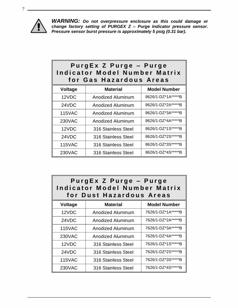
WARNING: Do not overpressure enclosure as this could damage or
change factory setting of PURGEX Z – Purge Indicator pressure sensor. Pressure sensor burst pressure is approximately 5 psig (0.31 bar).
P u r g E x Z P u r g e – P u r g e I n d i c a t o r M o d e l N u m b e r M a t r i x
f o r G a s H a z a r d o u s A r e a s
Voltage Material Model Number
12VDC Anodized Aluminum 8626/1-DZ*1A*****B
24VDC Anodized Aluminum 8626/1-DZ*2A*****B
115VAC Anodized Aluminum 8626/1-DZ*3A*****B
230VAC Anodized Aluminum 8626/1-DZ*4A*****B
12VDC 316 Stainless Steel 8626/1-DZ*1S*****B
24VDC 316 Stainless Steel 8626/1-DZ*2S*****B
115VAC 316 Stainless Steel 8626/1-DZ*3S*****B
230VAC 316 Stainless Steel 8626/1-DZ*4S*****B
P u r g E x Z P u r g e – P u r g e I n d i c a t o r M o d e l N u m b e r M a t r i x
f o r D u s t H a z a r d o u s A r e a s
Voltage Material Model Number
12VDC Anodized Aluminum 7626/1-DZ*1A*****B
24VDC Anodized Aluminum 7626/1-DZ*2A*****B
115VAC Anodized Aluminum 7626/1-DZ*3A*****B
230VAC Anodized Aluminum 7626/1-DZ*4A*****B
12VDC 316 Stainless Steel 7626/1-DZ*1S*****B
24VDC 316 Stainless Steel 7626/1-DZ*2S*****B
115VAC 316 Stainless Steel 7626/1-DZ*3S*****B
230VAC 316 Stainless Steel 7626/1-DZ*4S*****B
7
NOTE: The equipment installation must include only one of the
following gas inlet kits PSO-SCD-A, PSO-SCD-S, PSO-MCD-A, PSO-MCD-S, PSO-LCD-A, PSO-LCD-S, PSO-SMLC-A, PSO-SMLC-S, PSO-MMLCS-A, PSO-MMLC-S, PSO-LMLC-A or PSO-LMLC-S which are provided as part of the UL Classified Indicator PSCZ-XX or PSCZ-XXX.
8
Section 3
Introduction
Description: Type Z purging reduces the classification within a protected electronics enclosures from Division 2 or Zone 2 to nonhazardous. Failure to maintain pressure within the protected enclosure shall be detected by an alarm or indicator at the electronics enclosure. The dilution purge time shall be a manual operation and once the electronics enclosure has been purged of ignitable or flammable concentrations, only positive pressure setting of at least 0.50 inches H2O (1.25 mbar) is required to be maintained within the electronics enclosure and it is not necessary to remove power from the protected equipment upon the loss of purge pressure.
The PURGEX Z – Purge Indicator is used to provide safe monitoring of electrical equipment in Division 2 and Zone 2 hazardous areas, which can be used to prevent the possibility of fire or explosion inside the enclosure of energized electrical equipment, a protective gas supply is used to dilute potentially flammable materials to an acceptable level, creating a safe area for the electrical equipment within the enclosure. Positive pressure prevents the ingress of flammable materials in the surrounding atmosphere from entering into the enclosure, as long as positive pressure is maintained. After the enclosure is purged, power may be manually applied to the protected electrical equipment.
The PURGEX Z – Purge Indicator provides an objective evidence of the presence of adequate positive purge pressure within the electrical equipment enclosure. A normally open differential pressure switch continuously compares the pressure inside the monitored electronics enclosure with respect to the atmospheric pressure surrounding the electronics enclosure. When the monitored electronics enclosure register’s a pressure of at least 0.50 inches H2O (1.25 mbar) above the reference atmospheric pressure a manually controlled dilution time cycle may then begin. Typically, a minimum dilution time cycle is specified to ensure that at least five times the volume of free space in the electronics enclosure is exchanged before power is manually applied to the electrical equipment. (The number of exchanged volumes may be higher in some situations). After the manual dilution time cycle has elapsed and the monitored electronics enclosure pressure is being maintained above 0.50 inches H2O (1.25 mbar), power may be manually applied to the electrical equipment within the purged electronics enclosure.
9
The PURGEX Z – Purge Indicator is designed to indicate the presence of purge pressure from one pressure reference point. Several electronics enclosures can be installed in series with purge gas being introduced into the first electronics enclosure and the PURGEX Z – Purge Indicator monitoring the last electronics enclosure in the series; multiple electronics enclosures can now be monitored using only one PURGEX Z – Purge Indicator. The pressure inside the monitored electronics enclosures must maintain at least 0.50 inches H2O (1.25 mbar) higher than the atmospheric pressure surrounding the electronics enclosure. This ensures that hazardous materials are not going to ingress into the pressurized and now protected electronics enclosures. If any of the electronics enclosures installed in the series door is opened, pressure will show to be below the required 0.50 inches H2O (1.25 mbar) in all electronics enclosures.
The exhaust vent which comes as part of the PURGEX Z – Purge Indicator casing, can exhaust purge gas from enclosures with volumes up to 15 cubic feet (425 liters). For enclosure with volumes above 15 cubic feet (425 liters) and up to 200 cubic feet (5,663 liters) an additional exhaust vent will be required to properly vent the larger volume of purge gas from the enclosure safely. For proper selection of components for your purge application, refer to the PurgeEx Interactive Product Selector, which can be found on the home page of our web site www.rstahl.com.
The PURGEX Z – Purge Indicator uses two different purge methods to dilute the electronics enclosure and maintain at least 0.50 inches H2O (1.25 mbar); continuous dilution or leakage compensation. Continuous dilution is a method of maintaining pressure in an electronics enclosure in which after the electronics enclosure has been diluted below the required lower explosive limit (LEL) the protective gas is passed continuously through the electronics enclosure at a pressure above that of the required 0.50 inches H2O (1.25 mbar) and discharged to the outside atmosphere through an exhaust vent. The same volume of purge gas is maintained during and after the dilution time cycle. Continuous dilution is normally used for maintaining and controlling heat buildup from the electronics within the pressurized enclosure by continuously exchanging purge gas through the electronics enclosure to atmosphere. STAHL offers three sizes of continuous dilution models a Small Continuous Dilution Purge Gas Inlet Kit for enclosures with a volume up to 15 cubic feet (425 liters), a Medium Continuous Dilution Purge Gas Inlet Kit for enclosures with volumes up to 75 cubic feet (2,125 liters) and a Large Continuous Dilution Purge Gas Inlet Kit for enclosures with volumes up to 200 cubic feet (5,663 liters). All three Small, Medium and Large Continuous Dilution Purge Gas Inlet Kits are available in materials of anodized aluminum or 316 stainless steel.
10
The second purge method offered by R. STAHL, Inc. leakage compensation, which allows a higher volume of protective gas supply to be manually selected to speed up dilution time of potentially flammable materials to an acceptable level, permitting a more-rapid application of initial power, or restoration of power to protected electrical equipment, after service. When the dilution cycle has elapsed, the large volume of purge gas can be manually turned off. A volume of purge gas larger than the leak rate of the electronics enclosure will be introduced into the now protected electronics enclosure to maintain at least 0.50 inches H2O (1.25 mbar). Leakage compensation is normally used to conserve purge gas when utilities are at a premium. R. STAHL, Inc. offers three sizes of leakage compensation models a Small Leakage Compensation Purge Gas Inlet Kit for enclosures with a volume up to 15 cubic feet (425 liters), a Medium Leakage Compensation Purge Gas Inlet Kit for enclosures with volumes up to 75 cubic feet (2,125 liters) and a Large Leakage Compensation Purge Gas Inlet Kit for enclosures with volumes up to 200 cubic feet (5,663 liters). All three Small, Medium and Large Leakage Compensation Purge Gas Inlet Kits are available in materials of anodized aluminum or 316 stainless steel.
For installations that require a back-up pressure relief vent for the purged enclosure, R. STAHL, Inc. offers three sizes of back-up pressure relief vent kits. A Small Back-Up Vent for enclosures with a volume up to 15 cubic feet (425 liters), Medium Back-Up Vent for enclosures with volumes up to 75 cubic feet (2,125 liters) and a Large Back-Up Vent for enclosures with volumes up to 200 cubic feet (5,663 liters). All three Small, Medium and Large Back-Up Vents are constructed of 316 stainless steel with an option of mounting on the top or side of an enclosure.
For purged electronic enclosures monitored by a PURGEX Z – Purge Indicator, which has electrical components with higher surface temperatures than the temperature class of the hazardous area in which the electrical equipment is located, STAHL offers a Back-Up Purge Gas Kit, which is used in the event that the initial protective gas supply is lost, a back-up source of bottled protective gas is automatically applied to the protected enclosure. Electrical equipment protected with this feature is allowed to cool adequately, while preventing the ingress of flammable materials in the surrounding atmosphere from entering into the electronics enclosure as long as positive pressure is maintained.
For purged enclosures using the Back-Up Purge Gas Kits, a Protective Gas Loss Indicator can be installed for remote protective bottled gas purge supply monitoring. By installing a Protective Gas Loss Indicator on the protective back-up bottled purge gas supply line, an alarm signal will be sent if the protective back-up bottled purge gas supply has been depleted, when bottled gas is used as a back-up gas source.
WARNING: Failure to heed the following information may lead to
injury of personnel or equipment damage.
CAUTION: Electrical equipment components may be hot even when
power is not applied. Take appropriate precautions to prevent injury from contact with hot items.
11
WARNING: Failure to allow adequate cooling of electrical equipment
components with hot surfaces before opening the purged enclosure can lead to injury of personnel or equipment damage.
For applications where thermal management of electrical cabinets and control panels are required; R. STAHL, Inc. offers Vortex Cabinet Cooler Systems, which provide cooling capacities for your application and maintain a NEMA 4 or 4X (IP66) rating for installation and use in hazardous area. Contact your local R. STAHL, Inc. representative or the factory for sizing of system and installation information.
NOTE: There are special modifications and sizing requirements to
be made before Vortex Cabinet Coolers are able to be installed and used in a hazardous area.
NOTE: In the interest of completeness, included in this manual with
the PURGEX Z – Purge Indicator information is additional information pertaining to options not included with your equipment.
For purged and / or increased safety enclosure that require viewing of components mounted within the enclosure R. STAHL, Inc. offers Increased Safety Window Kits in 5 different window viewing sizes with bezels available in anodized aluminum or 316 stainless steel.
12
Section 4
Installation
WARNING: Before attempting to install the PURGEX Z – Purge
Indicator, review all the material and all safety information in this manual and all other applicable documents.
WARNING: Applicable permits must be obtained and appropriate
precautions must be taken to prevent possible injury to personnel or equipment damage when installing the PURGEX Z – Purge Indicator.
NOTE: Refer to all ATEX, CSA, IECEx, NEC, NFPA and UL certificates
for any Special Conditions of Use. If the sign “X” is placed after the certificate number, it indicates that the equipment or protective system is subject to special conditions for safe use specified in the schedule of the certificate.
NOTE: Review all material and safety information in this manual and
install in accordance with this document and all other applicable ATEX, CSA, IECEx, NEC, NFPA 496 and UL standards.
Mounting: Review all of the material in this manual prior to installing the PURGEX Z – Purge Indicator to the enclosure it will be monitoring. If you have any questions, please contact your local R. STAHL, Inc. representative or the factory (refer to Getting Help page 45). For installing the PURGEX Z – Purge Indicator to an enclosure and for attaching and routing of wires for power and alarm signals, refer to Installation Flow Diagrams (refer to page 35), Dimensional General Assembly (refer to page 39), Mounting Hole Template (refer to page 40) and Wiring Diagram (refer to page 41).
Step 1:
Make sure that area surrounding the enclosure to be monitored by the PURGEX Z – Purge Indicator is known to be non-hazardous.
Step 2:
Make sure that all power is removed from the electrical equipment located in the enclosure where the PURGEX Z – Purge Indicator will be installed.
13
Step 3:
Choose a mounting location for the PURGEX Z – Purge Indicator on the enclosure in a location farthest from the protective supply gas inlet in order to allow proper enclosure dilution, refer to Installation Flow Diagrams (refer to page 35) for possible mounting location. The chosen location should also permit adequate viewing of the green indicator light and proper purge exhaust venting.
Step 4:
Use Mounting Hole Template (refer to page 40) to accurately locate the mounting holes. Use the Mounting Hole Template to draw and print a 1 to 1 scale drawing. Tape the 1 to 1 drawing to the outside of enclosure. The required hole locations can then be transferred and / or marked using the centers of the holes as shown on the 1 to 1 drawing.
Step 5:
Drill or punch all holes, per the sizes and locations specified on the Mounting Hole Template (refer to page 40).
Step 6:
Before mounting the PURGEX Z – Purge Indicator install the o-ring provided into its appropriate groove. Next, line up PURGEX Z – Purge Indicator on the outside of enclosure, aligning the PURGEX Z – Purge Indicator to the mounting holes produced in Step 5.
Step 7:
Using the five (5) each stainless steel, 1/4–20 UNC x 1/2 long screws, flat and split lock washers provided, mount the PURGEX Z – Purge Indicator to enclosure. Tighten bolts until the o-ring seal is completely compressed against the surface of the enclosure, which will about 5 Foot Pound (6.7 Meter Newton) using a #3 Phillips head tool.
Step 8:
Connect 16 AWG, three-conductor wire (refer to Power Source Specifications, refer to page 16) for power to the PURGEX Z – Purge Indicator. Use Wiring Diagram (refer to page 41) for wire terminal strip locations.
CAUTION: This apparatus must be earth grounded. Refer to Figure
1 for proper ground connection detail.
14
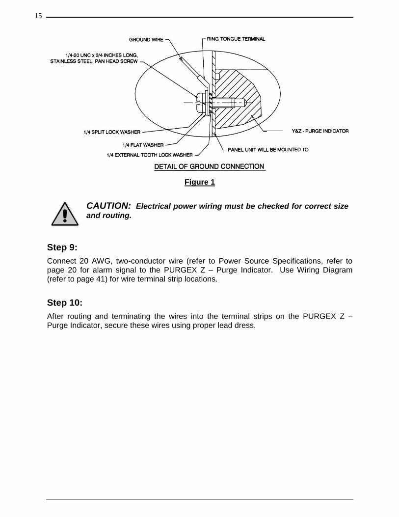
Figure 1
CAUTION: Electrical power wiring must be checked for correct size
and routing.
Step 9:
Connect 20 AWG, two-conductor wire (refer to Power Source Specifications, refer to page 20 for alarm signal to the PURGEX Z – Purge Indicator. Use Wiring Diagram (refer to page 41) for wire terminal strip locations.
Step 10:
After routing and terminating the wires into the terminal strips on the PURGEX Z – Purge Indicator, secure these wires using proper lead dress.
15
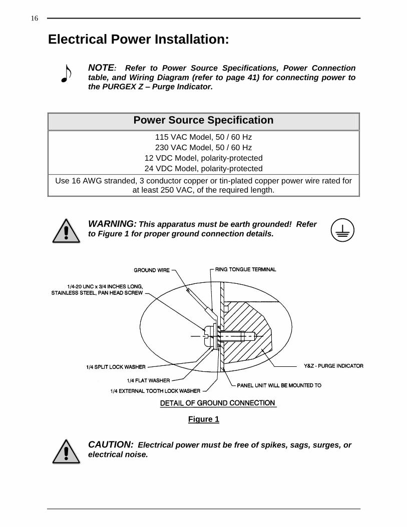
Electrical Power Installation:
NOTE: Refer to Power Source Specifications, Power Connection
table, and Wiring Diagram (refer to page 41) for connecting power to the PURGEX Z – Purge Indicator.
Power Source Specification
115 VAC Model, 50 / 60 Hz
230 VAC Model, 50 / 60 Hz
12 VDC Model, polarity-protected
24 VDC Model, polarity-protected
Use 16 AWG stranded, 3 conductor copper or tin-plated copper power wire rated for at least 250 VAC, of the required length.
WARNING: This apparatus must be earth grounded! Refer
to Figure 1 for proper ground connection details.
Figure 1
CAUTION: Electrical power must be free of spikes, sags, surges, or
electrical noise.
16
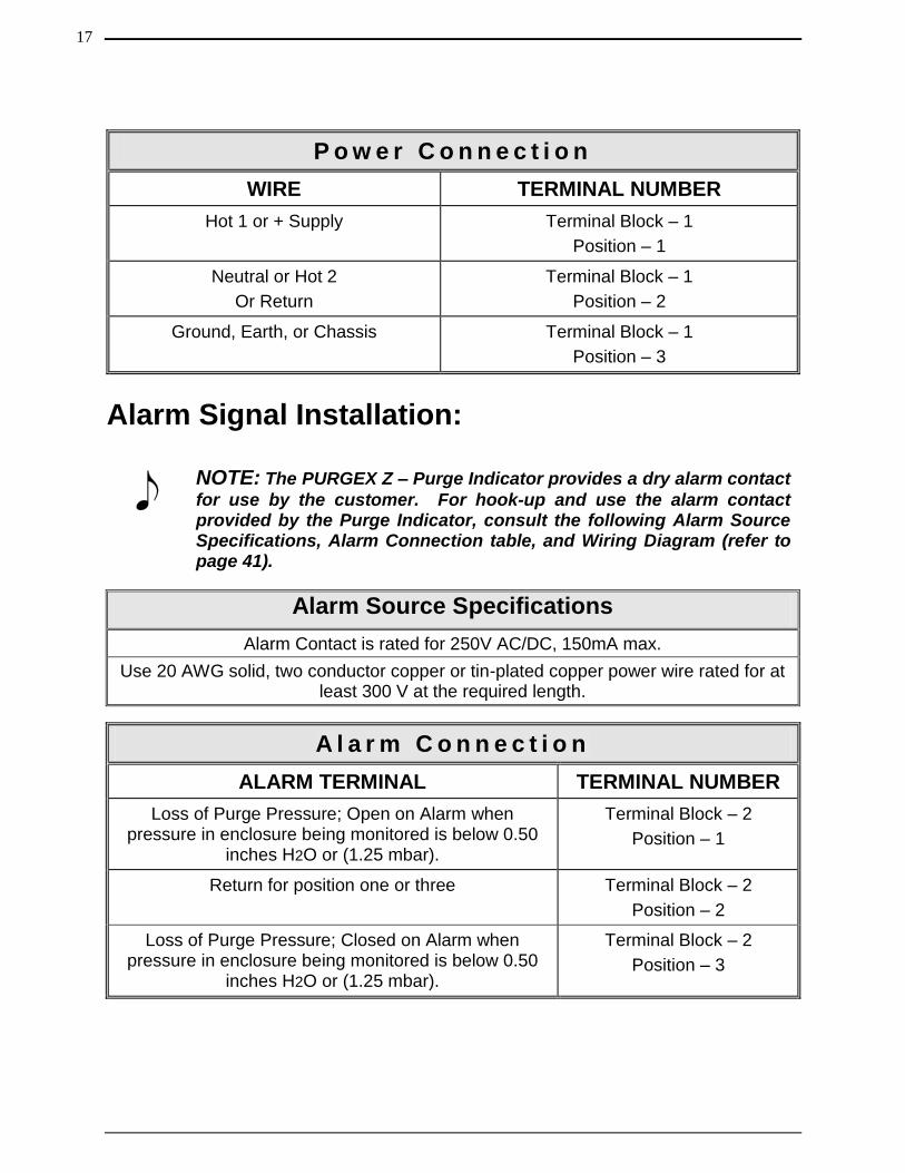
P o w e r C o n n e c t i o n
WIRE TERMINAL NUMBER
Hot 1 or + Supply Terminal Block – 1
Position – 1
Neutral or Hot 2
Or Return
Terminal Block – 1
Position – 2
Ground, Earth, or Chassis Terminal Block – 1
Position – 3
Alarm Signal Installation:
NOTE: The PURGEX Z – Purge Indicator provides a dry alarm contact
for use by the customer. For hook-up and use the alarm contact provided by the Purge Indicator, consult the following Alarm Source Specifications, Alarm Connection table, and Wiring Diagram (refer to page 41).
Alarm Source Specifications
Alarm Contact is rated for 250V AC/DC, 150mA max.
Use 20 AWG solid, two conductor copper or tin-plated copper power wire rated for at least 300 V at the required length.
A l a r m C o n n e c t i o n
ALARM TERMINAL TERMINAL NUMBER
Loss of Purge Pressure; Open on Alarm when pressure in enclosure being monitored is below 0.50
inches H2O or (1.25 mbar).
Terminal Block – 2
Position – 1
Return for position one or three Terminal Block – 2
Position – 2
Loss of Purge Pressure; Closed on Alarm when pressure in enclosure being monitored is below 0.50
inches H2O or (1.25 mbar).
Terminal Block – 2
Position – 3
17
Section 5
Startup Procedures
Continuous Dilution Initial Startup Procedure: The following procedure should be performed when initially starting up a system using a Continuous Dilution purge gas inlet system and to calculate the manual dilution time for any purged electrical equipment that uses the PURGEX Z – Purge Indicator to monitor the electrical equipment enclosure purge pressure.
WARNING: Failure to heed the following information may lead to
injury of personnel or equipment damage.
WARNING: Do not open the electrical equipment enclosure in a
hazardous area even when de-energized unless area has been properly tested and is known to not contain explosive materials.
WARNING: Before initially starting the equipment, electrical power
wiring must be checked for correct size and routing.
NOTE: Refer to all ATEX, CSA, IECEx, NEC, NFPA and UL certificates
for any Special Conditions of Use. If the sign “X” is placed after the certificate number, it indicates that the equipment or protective system is subject to special conditions for safe use specified in the schedule of the certificate.
NOTE: Review all material and safety information in this manual and
install in accordance with this document and all other applicable ATEX, CSA, IECEx, NEC, NFPA 496 and UL standards.
Step 1:
Make sure that area surrounding the PURGEX Z – Purge Indicator and the electronics enclosure the PURGEX Z – Purge Indicator will be monitoring is known to be non-hazardous.
18
Step 2:
After it has been assured that area surrounding the PURGEX Z – purge Indicator and the electronics enclosure the PURGEX Z – Purge Indicator will be monitoring is known to be non-hazardous, open electronics enclosure door.
Step 3:
After opening electronics enclosure door, install Continuous Dilution Purge Gas Inlet Kit per installation instructions located in Purge Gas Inlet Kits Users Manual.
Step 4:
With electronics enclosure door still open, turn on purge protective gas supply to electronics enclosure by turning the Continuous Dilution Purge Gas Inlet Kit shutoff valve to the ON position and verify that enclosure is being supplied with purge gas.
Step 5:
After it has been verified that the enclosure is being supplied with purge gas, turn off purge gas supply pressure to electronics enclosure at Continuous Dilution Purge Gas Inlet Kit pressure regulator.
Step 6:
With protective gas supply pressure off at Continuous Dilution Purge Gas Inlet Kit regulator, close and latch electronics enclosure door.
Step 7:
With electronics enclosure door closed and latched, apply power to electrical equipment in enclosure, which should also apply power to the PURGEX Z – Purge Indicator.
WARNING: DO NOT TURN ON POWER TO ELECTRICAL
EQUIPMENT LOCATED IN ENCLOSURE PURGEX Z – PURGE INDICATOR WILL BE MONITORING PURGE PRESSURE, UNLESS AREA HAS BEEN PROPERLY TESTED AND IS KNOWN NOT TO CONTAIN EXPLOSIVE MATERIALS.
Step 8:
With power applied to the PURGEX Z – Purge Indicator, raise the pressure of the purge protective gas using the Continuous Dilution Purge Gas Inlet Kit pressure regulator until the PURGEX Z – Purge Indicator green light comes on.
19
Step 9:
With the PURGEX Z – Purge Indicator green light on, turn off the protective gas supply to electronics enclosure at purge gas shutoff valve on the Continuous Dilution Purge Gas Inlet Kit manifold.
Step 10:
With protective gas supply turned off at Continuous Dilution Purge Gas Inlet Kit shutoff valve, record the pressure reading on the Continuous Dilution Purge Gas Inlet Kit pressure gauge. The recorded pressure will be used to calculate the purge dilution time before power can be applied to electronics within the purged enclosure. Only the pressure recorded when the Continuous Dilution Purge Gas Inlet Kit shutoff valve is in the OFF position should be used to calculate the dilution time required before power can be connected to the electronics with in the enclosure.
Step 11:
After recording the pressure reading on the Continuous Dilution Purge Gas Inlet Kit pressure gauge, which will be used to calculate the purge dilution time before power can be applied to electronics within the purged enclosure, turn on protective gas supply to electronics enclosure by turning the Continuous Dilution Purge Gas Inlet Kit shutoff valve to the ON position.
Step 12:
With purge protective gas being supplied to electronics enclosure and PURGEX green indicator light illuminated, start the manual dilution time cycle. The manual dilution time cycle must be long enough to ensure that at least five (5) times the volume of free space in the electronics enclosure of purge protective gas is exchanged before power can be manually applied to the electrical equipment inside the purged enclosure.
NOTE: If you are using one of R. STAHL, Inc. Continuous Dilution
Purge Gas Inlet Kits to supply purge gas to an enclosure the PURGEX Z – Purge Indicator is monitoring refer to R. STAHL, Inc. web site to use Dilution Time Software to calculate dilution time for your size enclosure. The Dilution Software can only be used if you are using a R. STAHL, Inc. Continuous Dilution Purge Gas Inlet Kit, as the Dilution Time Software calculations are based on empirical test performed with R. STAHL, Inc. Continuous Dilution Purge Gas Inlet Kits and proprietary exhaust vents.
20
NOTE: The dilution time cycle can be reduced by increasing the
pressure of purge gas being supplied into the enclosure. Start at Step 9 and increase the pressure being read on the Continuous Dilution Purge Gas Inlet Kit pressure regulator. Use the new pressure reading to calculate a lower dilution time, repeating until an appropriate dilution time is reached.
WARNING: The number of exchanged volumes may be higher in
some situations.
Step 13:
After a manual dilution time has been established, the manual dilution time and Continuous Dilution Purge Gas Inlet Kit regulator gauge pressure reading should be recorded for used during any future maintenance and / or service of the purge enclosure being monitored by the PURGEX Z – Purge Indicator.
NOTE: If purge pressure becomes less than 0.50 inches H2O (1.25
mbar), the PURGEX Z – Purge Indicator does not disconnect power to the electrical equipment within the enclosure it has been monitoring, it will only alarm.
21
Manual Leakage Compensation Initial Startup Procedure: The following procedure should be performed when initially starting up a system using a R. STAHL, Inc. Manual Leakage Compensation Purge Gas Inlet Kit and to calculate the dilution time for any purged electrical equipment that uses the PURGEX Z – Purge Indicator to monitor the electrical equipment enclosure purge pressure.
WARNING: Failure to heed the following information may lead to
injury of personnel or equipment damage.
WARNING: Do not open the electrical equipment enclosure in a
hazardous area even when de-energized unless area has been properly tested and is known to not contain explosive materials.
WARNING: Before initially starting the equipment, electrical power
wiring must be checked for correct size and routing.
NOTE: Refer to all ATEX, CSA, IECEx, NEC, NFPA and UL certificates
for any Special Conditions of Use. If the sign “X” is placed after the certificate number, it indicates that the equipment or protective system is subject to special conditions for safe use specified in the schedule of the certificate.
NOTE: Review all material and safety information in this manual and
install in accordance with this document and all other applicable ATEX, CSA, IECEx, NEC, NFPA 496 and UL standards.
Step 1:
Make sure that area surrounding the PURGEX Z – Purge Indicator and the electronics enclosure the PURGEX Z – Purge Indicator will be monitoring is known to be non-hazardous.
Step 2:
After assuring area surrounding the PURGEX Z – purge Indicator and the electronics enclosure the PURGEX Z – Purge Indicator will be monitoring is known to be non-hazardous, open electronics enclosure door.
22
Step 3:
After opening electronics enclosure door, install Manual Leakage Compensation Purge Gas Inlet Kit per installation instructions located in Purge Gas Inlet Kits User’s Manual.
Step 4:
With electronics enclosure door still open, turn on purge protective gas supply to electronics enclosure by turning the Manual Leakage Compensation Purge Gas Inlet Kit shutoff valve to the ON position and verify that enclosure is being supplied with purge gas.
Step 5:
After it has been verified that the enclosure is being supplied with purge gas, turn off purge gas supply pressure to electronics enclosure at Manual Leakage Compensation Purge Gas Inlet Kit pressure regulator.
Step 6:
With protective gas supply pressure to electronics enclosure turned off at Manual Leakage Compensation Purge Gas Inlet Kit pressure regulator, assure that the manual dilution valve on the Manual Leakage Compensation Purge Gas Inlet Kit manifold block is in the OFF position.
Step 7:
After assuring that the manual dilution valve on the Manual Leakage Compensation Purge Gas Inlet Kit manifold block is in the OFF position, make sure that the leakage compensation valve is completely closed on the Manual Leakage Compensation Purge Gas Inlet Kit manifold block.
Step 8:
After assuring that leakage compensation valve is completely closed on the Manual Leakage Compensation Purge Gas Inlet Kit manifold block, close and latch electronics enclosure door.
Step 9:
With electronics enclosure door closed and latched, apply power to electrical equipment in enclosure, which should also apply power to the PURGEX Z – Purge Indicator.
23
WARNING: DO NOT TURN ON POWER TO ELECTRICAL
EQUIPMENT LOCATED IN ENCLOSURE PURGEX Z – PURGE INDICATOR WILL BE MONITORING PURGE PRESSURE, UNLESS AREA HAS BEEN PROPERLY TESTED AND IS KNOWN NOT TO CONTAIN EXPLOSIVE MATERIALS.
Step 10:
With power applied to the PURGEX Z – Purge Indicator, turn on protective gas supply pressure at Manual Leakage Compensation Purge Gas Inlet Kit pressure regulator.
Step 11:
With protective gas supply pressure turned on at Manual Leakage Compensation Purge Gas Inlet Kit pressure regulator and shutoff valve in the OFF position, open leakage compensation valve on the Manual Leakage Compensation Purge Gas Inlet Kit manifold block until the PURGEX Z – Purge Indicator green light comes on.
Step 12:
With the PURGEX Z – Purge Indicator green light on, using jam nut, lock leakage compensation valve in place on the Manual Leakage Compensation Purge Gas Inlet Kit manifold block to maintain leakage compensation volume setting.
Step 13:
With the PURGEX Z – Purge Indicator green light on and the leakage compensation valve locked into place, record the pressure reading on the Manual Leakage Compensation Purge Gas Inlet Kit pressure gauge. The recorded pressure will be used to calculate the purge dilution time before power can be applied to electronics within the purged enclosure. Only the pressure recorded when the Manual Leakage Compensation Purge Gas Inlet Kit is in the OFF position should be used to calculate the dilution time required before power can be connected to the electronics with in the enclosure.
Step 14:
With leakage compensation purge protective gas being supplied to electronics enclosure and PURGEX Z – Purge Indicator green indicator light illuminated, start the manual dilution time cycle by manually turning the dilution valve on the Manual Leakage Compensation Purge Gas Inlet Kit shutoff valve to the ON position. The manual dilution time delay must be long enough to ensure that at least five (5) times the volume of free space in the electronics enclosure of purge protective gas is exchanged before power can be manually applied to the electrical equipment inside the purged enclosure.
24
WARNING: The number of exchanged volumes may be higher in
some situations.
NOTE: If you are using one of R. STAHL, Inc. Manual Leakage
Compensation Purge Gas Inlet Kits to supply purge gas to enclosure the PURGEX Z – Purge Indicator will be monitoring refer to R. STAHL, Inc. web site to use Dilution Time Software to calculate manual dilution time for your size enclosure. The Dilution Software can only be used if you are using a R. STAHL, Inc. Manual Leakage Compensation Purge Gas Inlet Kit, as the Dilution Time Software calculations are based data from test performed on R. STAHL, Inc. Manual Leakage Compensation Purge Gas Inlet Kits and proprietary exhaust vents.
Step 15:
After the manual dilution time has elapsed, manually turn the Manual Leakage Compensation Purge Gas Inlet Kit shutoff valve to the OFF position. Allowing only enough purge gas volume into the now protected enclosure to maintain a pressure above the required 0.50 inches H2O (1.25 mbar) through the leakage compensation valve port.
Step 16:
After a manual dilution time has been established, the manual dilution time and Manual Leakage Compensation Purge Gas Inlet Kit regulator gauge pressure reading should be recorded for used during any future maintenance or service of the purge enclosure being monitored by the PURGEX Z – Purge Indicator.
NOTE: If purge pressure becomes less than 0.50 inches H2O (1.25
mbar), the PURGEX Z – Purge Indicator does not shuts off power to the electrical equipment it has been monitoring, it will only alarm.
25
Continuous Dilution Maintenance or Service Shutdown and Startup Procedure:
The following procedure should be performed when shutting down and re-starting any purged electrical equipment that uses a Continuous Dilution Purge Gas Inlet Kit and the PURGEX Z – Purge Indicator to monitor the electronic equipment enclosure purge pressure, which requires maintenance or service.
WARNING: Failure to heed the following information may lead to
injury of personnel or equipment damage.
CAUTION: Do not open the electrical equipment enclosure in a
hazardous area even when de-energized unless area has been properly tested and is known to not contain explosive materials.
WARNING: Applicable permits must be obtained and appropriate
precautions must be taken to prevent possible injury to personnel or equipment damage when installing the PURGEX Z – Purge Indicator.
CAUTION: Electrical equipment components may be hot even when
power is not applied. Take appropriate precautions to prevent injury from contact with hot items.
Step 1:
Properly disconnect power from all purged enclosure electronics that uses the PURGEX Z – Purge Indicator to monitor the electronics enclosure purge pressure, which requires maintenance or servicing.
Step 2:
After power has been disconnected from the electronics within protective enclosure, shut off purge gas supply at the Continuous Dilution Purge Gas Inlet Kit shutoff valve. Not at the Continuous Dilution Purge Gas Inlet Kit pressure regulator. The Continuous Dilution Purge Gas Inlet Kit pressure regulator setting should remain the same to keep the purge gas CFM (LPM) the same as what was established during the initial manual dilution time set up.
26
Step 3:
With power disconnected and purge gas supply properly shut off, the electronics enclosure door may now be opened and maintenance or service can begin.
CAUTION: Electrical equipment components may be hot even when
power is not applied. Take appropriate precautions to prevent injury from contact with hot items.
Step 4:
After maintenance and / or servicing have been completed, properly close and latch electronics enclosure door.
Step 5:
After electronics enclosure door has been properly closed and latched, turn on purge gas supply to electronics enclosure using the Continuous Dilution Purge Gas Inlet Kit shutoff valve. Continuous Dilution Purge Gas Inlet Kit pressure regulator setting should remain the same to keep the purge gas CFM (LPM) the same as what was established during the initial manual dilution time set up.
Step 6:
With purge protective gas being supplied to the electronics enclosure, begin the manual dilution time cycle. The manual dilution time cycle must be long enough to ensure that at least five (5) times the volume of free space in the electronics enclosure of purge protective gas is exchanged before power can be manually applied to the electrical equipment in the purged enclosure.
WARNING: The number of exchanged volumes may be higher in
some situations.
NOTE: The manual dilution time and Continuous Dilution Purge Gas
Inlet Kit regulator pressure should remain the same as what was established during the Continuous Dilution Initial Startup Procedure.
Step 7:
After the manual time cycle has elapsed, power can then be apply to the electrical equipment in the purged electronics enclosure.
27
Step 8:
After power has been applied to the electrical equipment in the purged electronics enclosure, the PURGEX Z – Purge Indicator green LED should be illuminated, indicating the required 0.50 inches H2O (1.25 mbar) pressure is being maintained within the now protected enclosure.
Step 9:
If power has been applied to the electrical equipment in the purged electronics enclosure and the PURGEX Z – Purge Indicator green LED is not illuminated, check to see if the electronics enclosure door is properly closed and latched or a proper Continuous Dilution Purge Gas Inlet Kit pressure regulator setting is being maintained.
NOTE: If green light does not remain on, check for the following
possible problems.
Purge pressure is set too low at the pressure regulator.
Enclosure door is open or allowing too much leakage.
Continuous Dilution Purge Gas Inlet Kit shutoff valve has not been put in the ON position.
28
Manual Leakage Compensation Maintenance or Service Shutdown and Startup Procedure:
The following procedure should be performed when shutting down and re-starting any purged electrical equipment that uses a R. STAHL, Inc. Manual Leakage Compensation Purge Gas Inlet Kit and the PURGEX Z – Purge Indicator to monitor the electronics enclosure purge pressure, which requires maintenance or service.
WARNING: Failure to heed the following information may lead to
injury of personnel or equipment damage.
CAUTION: Do not open the electrical equipment enclosure in a
hazardous area even when de-energized unless area has been properly tested and is known to not contain explosive materials.
WARNING: Applicable permits must be obtained and appropriate
precautions must be taken to prevent possible injury to personnel or equipment damage when installing the PURGEX Z – Purge Indicator.
CAUTION: Electrical equipment components may be hot even when
power is not applied. Take appropriate precautions to prevent injury from contact with hot items.
Step 1:
Properly disconnect power from all purged enclosure electronics that uses the PURGEX Z – Purge Indicator to monitor the electronics enclosure purge pressure, which requires maintenance or servicing.
Step 2:
After power has been disconnected from the electronics within the protected electronics enclosure, shut off purge gas supply at the Manual Leakage Compensation Purge Gas Inlet Kit shutoff valve. Not at the Manual Leakage Compensation Purge Gas Inlet Kit pressure regulator. The pressure regulator setting should remain the same to keep the purge gas CFM (LPM) the same as what was established during the initial manual dilution time set up.
29
Step 3:
With power disconnected and purge gas supply properly shut off, the electronics enclosure door may now be opened and maintenance or service can begin.
CAUTION: Electrical equipment components may be hot even when
power is not applied. Take appropriate precautions to prevent injury from contact with hot items.
Step 4:
After maintenance or servicing have been completed, properly close and latch electronics enclosure door.
Step 5:
After electronics enclosure door has been properly closed and latched, turn on purge gas supply to electronics enclosure using the Manual Leakage Compensation Purge Gas Inlet Kit shutoff valve. Manual Leakage Compensation Purge Gas Inlet Kit pressure regulator setting should remain the same to keep the purge gas CFM (LPM) the same as what was established during the initial manual leakage compensation dilution time set up.
Step 6:
With purge gas being supplied to the Manual Leakage Compensation Purge Gas Inlet Kit, start the manual dilution time cycle by manually turning the Manual Leakage Compensation Purge Gas Inlet Kit shutoff valve to the ON position. The manual leakage compensation dilution time cycle must be long enough to ensure that at least five (5) times the volume of free space in the enclosure of purge protective gas is exchanged before power can be manually applied to the electrical equipment in the purged enclosure.
WARNING: The number of exchanged volumes may be higher in
some situations.
NOTE: The manual leakage compensation dilution time and Manual
Leakage Compensation Purge Gas Inlet Kit regulator pressure should remain the same as what was established during the manual leakage compensation initial startup procedure.
30
Step 7:
After the manual leakage compensation dilution time has elapsed, turn the Manual Leakage Compensation Purge Gas Inlet Kit shutoff valve to the OFF position. Allowing only enough purge gas volume, into the now protected enclosure, to maintain a pressure above the required 0.50 inches H2O (1.25 mbar) from the leakage compensation valve port.
Step 8:
After the manual leakage compensation time cycle has elapsed, power can then be applied to the electrical equipment in the purged enclosure.
Step 9:
After power has been applied to the electrical equipment in the purged enclosure, the PURGEX Z – Purge Indicator green LED should be illuminated, indicating the required 0.50 inches H2O (1.25 mbar) pressure is being maintained within the now protected enclosure.
Step 10:
If power has been applied to the electrical equipment in the purged enclosure and the PURGEX Z – Purge Indicator green LED is not illuminated, check to see if the electronics enclosure door is properly latched or a proper Manual Leakage Compensation Purge Gas Inlet Kit pressure regulator setting is being maintained.
NOTE: If green light does not remain on, check for the following
possible problems.
Purge pressure is set too low at the pressure regulator.
Purge pressure is set too low at the leakage compensation valve.
Electronics enclosure door is open or allowing too much leakage.
31
Section 6
Documents
Installation Flow Diagram:
NOTE: Purge / Pressurization Systems Recommended Connections
for Single Enclosure are as follows:
1. Purge / pressurization system should be installed for best ease of viewing any system pressure gauges and / or visual alarms.
2. All tubing, piping and fittings should be selected and used that are suitable for the location they will be installed, used and protected from damage.
3. No valves shall be installed between the purge / pressurization system and enclosure.
4. Always refer to proper ATEX, CSA, IECEx, NEC, NFPA and UL standards for proper installation and required tests for certification of any complete purge / pressurization system installed on enclosure.
NOTE: Purge / Pressurization Systems Recommended Connections
for Multiple Enclosures will include the recommendations for single enclosure plus the following:
1. Enclosures in series should be connected from smallest to largest enclosure.
2. Connections between enclosures should be properly sized to allow proper operation of purge / pressurization system and proper purge gas flow through enclosures.
3. Conduit and wire ways can be utilized as protected enclosures or as connections between enclosures, as such volumes of conduit or wire ways should be added to overall volume to be diluted before power can be applied.
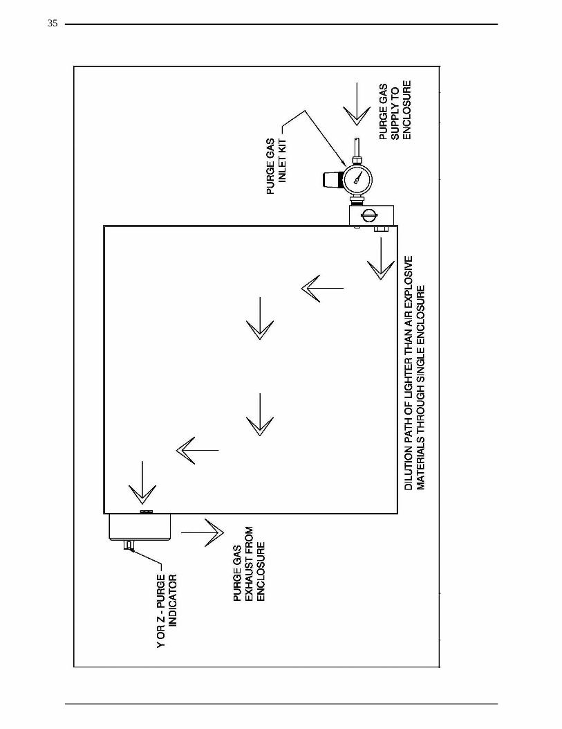
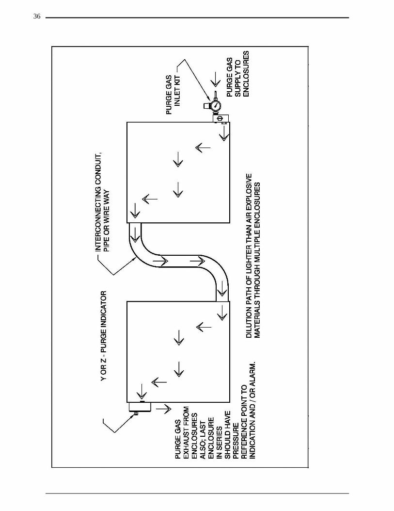
NOTE: Purge / Pressurization Systems Recommended Enclosure
Installation for Hazardous Areas with Flammable Gasses or Vapors that are Lighter than Air are as follows:
1. The purge gas inlet supply connection should enter the enclosure near the bottom corner of the enclosure.
2. As such the enclosure exhaust vent should be installed near an extreme opposite top corner of the enclosure.
3. Refer to drawing number on page 35 for illustration of lighter than air single enclosure flow diagram.
4. Refer to drawing on page 36 for illustration of lighter than air multiple enclosures flow diagram.
32
Installation Flow Diagrams (Continued):
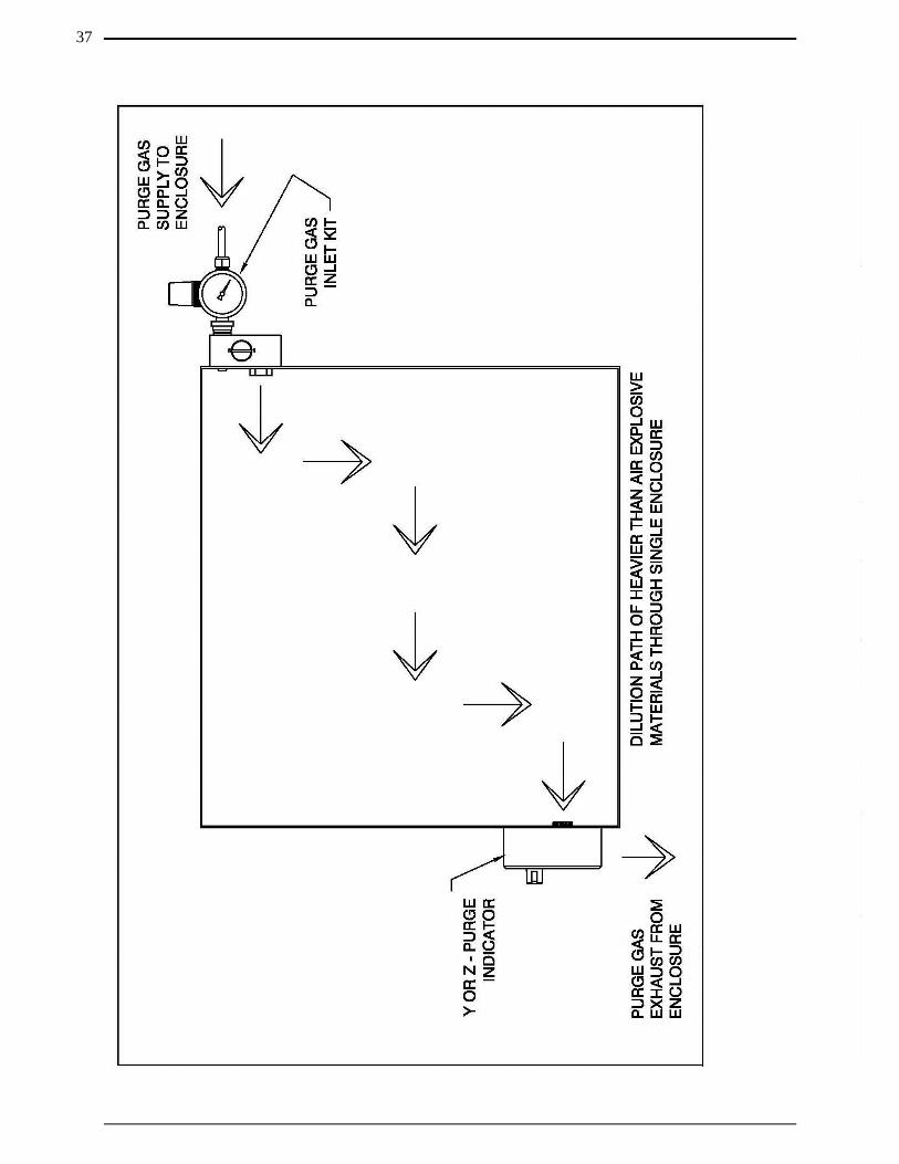
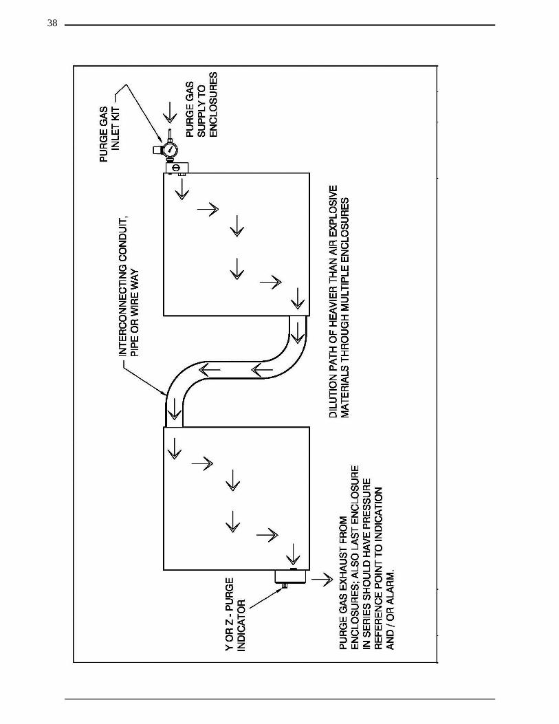
NOTE: Purge / Pressurization Systems Recommended Enclosure
Installation for Hazardous Areas with Flammable Gasses or Vapors that are Heavier than Air are as follows:
1. The purge gas inlet supply connection should enter the enclosure near the top corner of the enclosure.
2. As such the enclosure exhaust vent should be installed near an extreme opposite bottom corner of the enclosure.
3. Refer to drawing number on page 37 for illustration of heavier than air single enclosure flow diagram.
4. Refer to drawing number on page 38 for illustration of heavier than air multiple enclosures flow diagram.
Page 35 - Helpful in selecting optimal location for mounting the PURGEX Z – Purge Indicator on single enclosure applications with respect to the position of the purge system components for lighter than air hazardous materials.
Page 36 - Helpful in selecting optimal location for mounting the PURGEX Z – Purge Indicator on multiple enclosure applications with respect to the position of the purge system components for lighter than air hazardous materials.
Page 37 - Helpful in selecting optimal location for mounting the PURGEX Z – Purge Indicator on single enclosure applications with respect to the position of the purge system components for heavier than air hazardous materials.
Page 38- Helpful in selecting optimal location for mounting the PURGEX Z – Purge Indicator on multiple enclosure applications with respect to the position of the purge system components for heavier than air hazardous materials.
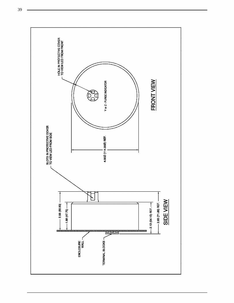
Dimensional General Assembly:
Page 39 – A dimensioned drawing of the PURGEX Z – Purge Indicator. Use for determining the optimal mounting location for the PURGEX Z – Purge Indicator and what area is required in enclosure it will be mounted.
33
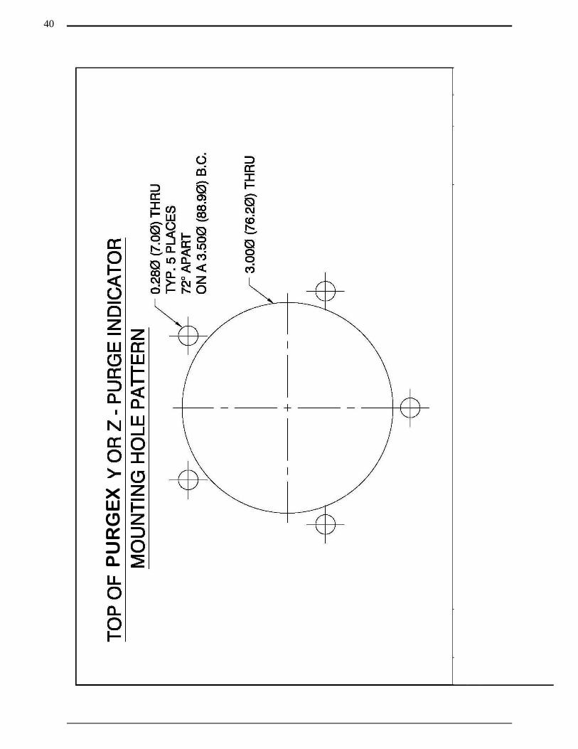
Mounting Hole Template:
Page 40 – A dimensioned drawing for creating a (1 to 1) scale drawing, helpful in transferring the position of the necessary mounting holes. Use this after determining the optimal location for the PURGEX Z – Purge Indicator.
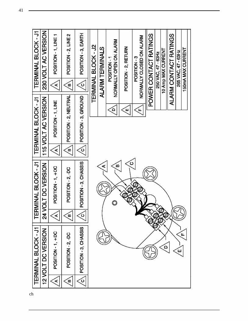
Wiring Diagram:
Page 41 - This drawing details the correct power and dry contact alarm-wiring hookup.
34
35
36
37
38
39
40
PU
RG
EX
ch
41
Section 7
Options
Continuous Dilution Purge Gas Inlet Kits: Continuous dilution is a method of maintaining pressure in an enclosure in which after the enclosure has been pre-purged the protective gas is passed continuously through the enclosure at a pressure above that of the specified minimum and discharged to the outside atmosphere through an exhaust vent. The same volume of purge gas is maintained during and after the dilution cycle.
R. STAHL, Inc. offers three sizes of continuous dilution models, the first size is our Small Continuous Dilution Purge Gas Inlet Kit for enclosures with a volume up to 15 cubic feet (425 liters). Model number PSO-SCD-A is our small aluminum version and model number PSO-SCD-S is our small stainless steel version. Purge gas supply inlet to Small Continuous Dilution Purge Gas Inlet Kit regulator is 1/4-18 FNPT.
The second size we offer is our Medium Continuous Dilution Purge Gas Inlet Kit for enclosures with volumes up to 75 cubic feet (2,125 liters). Model number PSO-MCD-A is our medium aluminum version and model number PSO-MCD-S is our medium stainless steel version. Purge gas supply inlet to Medium Continuous Dilution Purge Gas Inlet Kit regulator is 1/2-14 FNPT.
The third size we offer is our Large Continuous Dilution Purge Gas Inlet Kit for enclosures with volumes up to 200 cubic feet (5,663 liters). Model number PSO-LCD-A is our large aluminum version and model number PSO-LCD-S is our large stainless steel version. Purge gas supply inlet to Large Continuous Dilution Purge Gas Inlet Kit regulator is 1/2-14 FNPT. All Continuous Dilution Purge Gas Inlet Kits include input fittings, regulator, gauge, bracket and mounting hardware.
Increased Safety Window Kits: R. STAHL, Inc. also offers 5 different sizes of Increased Safety Window Kits with each size available in anodized aluminum or 316 stainless steel bezel material, which can be mounted on the side, top or bottom of an enclosure. Model number PSO-1/32DINW-A is our 1/32 Din size with anodized aluminum bezel, model number PSO-1/32DINW-S is our 1/32 Din size with 316 stainless steel bezel. Model number PSO-1/16DINW-A is our 1/16 Din size with anodized aluminum bezel, model number PSO-1/16DINW-S is our 1/16 Din size with 316 stainless steel bezel. Model number PSO-1/8DINW-A is our 1/8 Din size with anodized aluminum bezel, model number PSO-1/8DINW-S is our 1/8 Din size with 316 stainless steel bezel. Model number PSO-1/4DINW-A is our 1/4 Din size with anodized aluminum bezel, model number PSO-1/4DINW-S is our 1/4 Din size with 316 stainless steel bezel. Model number PSO-XLW-A is our X-Large size with anodized aluminum bezel, model number PSO-XLW-S is our X-Large size with 316 stainless steel bezel.
42
Manual Leakage Compensation Purge Gas Inlet Kits: Manual leakage compensation allows a higher volume of protective gas supply to be manually selected to speed up dilution of potentially flammable materials to an acceptable level, permitting a more-rapid application of initial power, or restoration of power to protected electrical equipment, after service. When the dilution cycle has elapsed, the large volume of purge gas can be manually turned off. A volume of purge gas larger than the leak rate of the enclosure will be introduced into the now protected enclosure to maintain at least 0.20 inches H2O (0.50 mbar).
R. STAHL, Inc. offers three sizes of leakage compensation models, the first size is our Small Manual Leakage Compensation Purge Gas Inlet Kit for enclosures with a volume up to 15 cubic feet (425 liters). Model number PSO-SMLC-A is our small aluminum version and model number PSO-SMLC-S is our small stainless steel version. Purge gas supply inlet to Small Manual Leakage Compensation Purge Gas Inlet Kit regulator is 1/4-18 FNPT.
The second size we offer is our Medium Manual Leakage Compensation Purge Gas Inlet Kit for enclosures with volumes up to 75 cubic feet (2,125 liters). Model number PSO-MMLC-A is our medium aluminum version and model number PSO-MMLC-S is our large stainless steel version. Purge gas supply inlet to Medium Manual Leakage Compensation Purge Gas Inlet Kit regulator is 1/2-14 FNPT.
The third size we offer is our Large Manual Leakage Compensation Purge Gas Inlet Kit for enclosures with volumes up to 200 cubic feet (5,663 liters). Model number PSO-LMLC-A is our large aluminum version and model number PSO-LMLC-S is our large stainless steel version. Purge gas supply inlet to Large Manual Leakage Compensation Purge Gas Inlet Kit regulator is 1/2-14 FNPT. All Leakage Compensation Purge Gas Inlet Kits include input fittings, regulator, gauge and manifold block.
Back-Up Vents: To protect the enclosure from over pressure; R. STAHL, Inc. offers three sizes of back-up vents. The first size is our Small Back–Up Vent for enclosures with a volume up to 15 cubic feet (425 liters). Model number PSO-SBUV-S is our small side mount version and model number PSO-SBUV-T is our small top mount version.
The second size we offer is our Large Back-Up Vent for enclosures with volumes up to 75 cubic feet (2,125 liters). Model number PSO-MBUV-S is our medium side mount version and model number PSO-MBUV-T is our medium top mount version.
The third size we offer is our Large Back-Up Vent for enclosures with volumes up to 200 cubic feet (5,663 liters). Model number PSO-LBUV-S is our large side mount version and model number PSO-LBUV-T is our large top mount version. All Back-Up Vents have a cracking pressure between 0.8 to 1.0 Inch H2O (2.0 to 2.5 mbar), are constructed of 316 stainless steel and come with all mounting hardware.
43
Vortex Cabinet Cooler Systems: For applications where thermal management of electrical cabinets and control panels are required; R. STAHL, Inc. offers Vortex Cabinet Cooler Systems, which provide cooling capacities for your application and maintain a NEMA 4 or 4X (IP66) rating for installation and use in hazardous area. Contact your local R. STAHL, Inc. representative or the factory for sizing of system and installation information.
NOTE: There are special modifications and sizing requirements to be
made before Vortex Cabinet Coolers are able to be installed and used in a hazardous area.
Back-Up Purge Gas Kit: In the event the initial protective purge gas supply is lost, this kit insures that a back up source of protective purge gas is automatically applied to the protected enclosure. R. STAHL, Inc. model number PSO-BUPG-K has inlets and outlet which are 3/8 – 18 FNPT.
NOTE: The Back-Up Purge Gas Kit requires a minimum air supply
pressure of 80 psig to function properly.
Protective Gas Loss Indicator Kit: An explosion-proof differential pressure switch may be installed to provide an alarm contact output signal to indicate the loss of primary purge gas supply. While a second can be installed to provide loss of back-up purge gas. Model number is PSO-PGLI-K.
Differential Pressure Gauge Kits: R. STAHL, Inc. also offers an all stainless steel Differential Pressure Gauge Kit, which can be mounted on the side, top or bottom of an enclosure. Model number PSO-DPG-L is our left side mount version, model number PSO-DPG-R is our right side mount version, model number PSO-DPG-T is our top mount version and model number PSO-DPG-B is our bottom mount version.
Increased Safety Enclosures: R. STAHL, Inc. also offers Increased Safety Enclosures that are available in powder coated carbon steel, 304 or 316 stainless steel in over 60 standard sizes or we can build a custom enclosure to your specifications. All have an IP66 / NEMA 4 ingress protection rating and an ambient temperature rating of - 40°F to 176°F (- 40°C to 80°C).
44

Section 8
Getting Help
Getting Help:
Answers to many questions concerning the PURGEX Z – Purge Indicator or any of our other products we offer can be found in this manual. If a problem or question is encountered that is not covered in the documentation provided, assistance is available Monday through Friday (except holidays), from 8 a.m. to 5 p.m. United States central time. To obtain assistance, please call R. STAHL, Inc. at 800-782-4357.
For assistance during times other than normal business hours, consult our World Wide Web Internet site at http://www.rstahl.com. This site includes equipment information, news releases, and other information. E-mail can be sent to [email protected].
45