Embed Size (px)
Citation preview
technical datasheettechnical datasheet
Each F80x module monitors the output of the eight fieldbus segments and indicates an alarm by means of a built-in, normally closed relay if any of the segments is shorted or below the minimum output voltage threshold. Failure of either of the bulk power input supplies is also annunciated. The alarm contacts are volt-free and galvanically isolated from other circuitry. Connections to the alarm relays are made via terminals on the F892-CA carrier. A separate alarm module is not required for this function. LED indicators also show the status of each F80x module and the eight individual segments. In normal operation, each segment LED is lit, showing that the segment is powered. If a segment is shorted, this LED is extinguished, and the module Alarm LED is lit.
A separate physical layer diagnostics module may be installed on the carrier to automatically collect and distribute additional diagnostic information for each of the eight fieldbus segments. For more information see the F809F product specification.
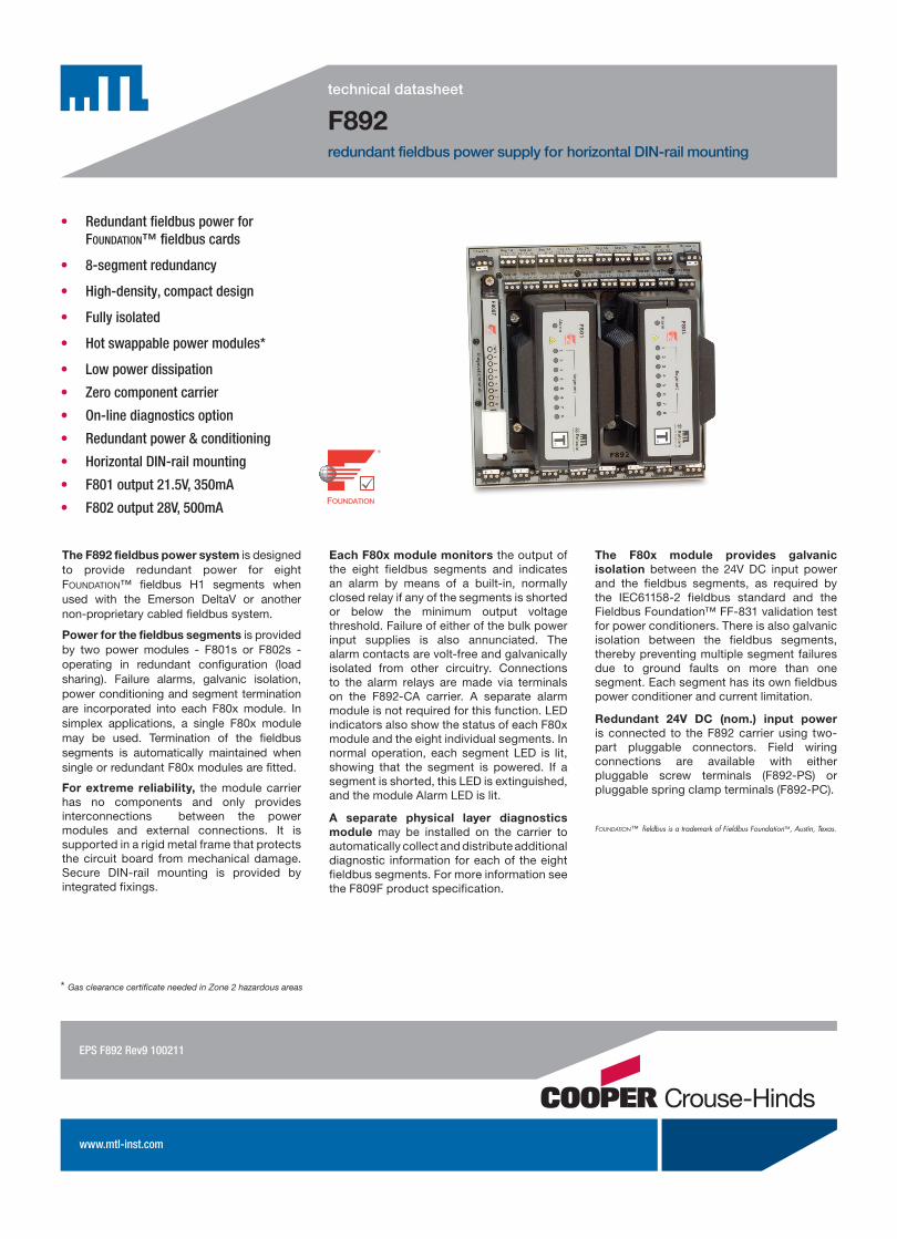
The F892 fieldbus power system is designed to provide redundant power for eight Foundation™ fieldbus H1 segments when used with the Emerson DeltaV or another non-proprietary cabled fieldbus system.
Power for the fieldbus segments is provided by two power modules - F801s or F802s - operating in redundant configuration (load sharing). Failure alarms, galvanic isolation, power conditioning and segment termination are incorporated into each F80x module. In simplex applications, a single F80x module may be used. Termination of the fieldbus segments is automatically maintained when single or redundant F80x modules are fitted.
For extreme reliability, the module carrier has no components and only provides interconnections between the power modules and external connections. It is supported in a rigid metal frame that protects the circuit board from mechanical damage. Secure DIN-rail mounting is provided by integrated fixings.
The F80x module provides galvanic isolation between the 24V DC input power and the fieldbus segments, as required by the IEC61158-2 fieldbus standard and the Fieldbus Foundation™ FF-831 validation test for power conditioners. There is also galvanic isolation between the fieldbus segments, thereby preventing multiple segment failures due to ground faults on more than one segment. Each segment has its own fieldbus power conditioner and current limitation.
Redundant 24V DC (nom.) input power is connected to the F892 carrier using two-part pluggable connectors. Field wiring connections are available with either pluggable screw terminals (F892-PS) or pluggable spring clamp terminals (F892-PC).
Foundation™ fieldbus is a trademark of Fieldbus Foundation™, Austin, Texas.
• RedundantfieldbuspowerforFoundation™ fieldbuscards
• 8-segmentredundancy
• High-density,compactdesign
• Fullyisolated
• Hotswappablepowermodules*
• Lowpowerdissipation
• Zerocomponentcarrier
• On-linediagnosticsoption
• Redundantpower&conditioning
• HorizontalDIN-railmounting
• F801output21.5V,350mA
• F802output28V,500mA
F892redundant fieldbus power supply for horizontal DIN-rail mounting
EPSF892Rev9100211
* Gas clearance certificate needed in Zone 2 hazardous areas

EUROPE (EMEA): +44 (0)1582 723633 THE AMERICAS: +1 800 835 7075 ASIA-PACIFIC: +65 6 487 7887
[email protected] [email protected] [email protected]
The given data is only intended as a product description and should not be regarded as a legal warranty of proper-ties or guarantee. In the interest of further technical developments, we reserve the right to make design changes.
SPECIFICATIONLocation of equipment
Safe area, Class I Div 2 Groups ABCD T4 orClass I Zone 2 IIC T4
INPUT F801 F802
Input voltage (DC) 19.2 - 30.0V 19.2 - 30.0VCurrent consumption(24V input, all outputs fully loaded)
3.5A* 6A*
Total Power dissipation(24V input, all outputs fully loaded) 20W* 24W*
* Redundant operation
OUTPUT F801 F802
Number of channels Eight (8) Eight (8)Voltage (DC) 21.5V - 24.0V 28.0V - 30.0VDesign current (per segment) 0 to 350mA 0 to 500mACurrent limit > 370mA > 520mAMinimum load 0mA 0mAIsolationFieldbus to input power: 250V AC rms withstandSegment to segment: 200V DC withstand
ALARMSAlarm contact rating
1A maximum @ 30V DC maximumAlarm contact status
Normally closed
Alarm threshold F801 F802
Segment output <19V DC <24V DC
ELECTRICAL CONNECTIONSSystem & optional Diagnostics segment terminals
3-way fixed screw terminal connector 0.14 to 2.5 mm2
Field & Power terminals Pluggable rising cage-clamp screw terminals (-PS) Conductor size: 0.14 to 2.5 mm2 Pluggable spring-clamp screw terminals (-PC) Conductor size: 0.2 to 2.5 mm2
Alarm / ground terminals4-way fixed screw terminal connector 0.14 to 2.5 mm2
Cable screen ground connections (version F.0 or higher)User-selectable jumper for segment shields: isolated (default) or interconnected and ground connection
TerminatorsA single termination is provided automatically when using either 1 or 2 power modules
ENVIRONMENTALAmbient temperature F801 F802
Operating (full load) —40°C to +65°C —40°C to +50°COperating (60% load) —40°C to +65°C —40°C to +65°CStorage —40°C to +85°C —40°C to +85°C
Note: Temperature range applies only when fitted to a horizontal DIN rail mounted on a vertical plane.
Ingress protectionIP20 to BS EN60529 (Additional protection by use of enclosure)
MECHANICALMounting method
Integrated fixings for 'Top hat' DIN rail, 35mm x 7.5mm to EN50022
WeightsF801: 1.45kgF802: 1.50kg F892-CA-P*: 1.10kg
The above diagram shows a block diagram of how the F892 is wired. Note that the Chassis Ground and Alarm connection are not shown. The Diagnostic module is also not shown (see the F809F product specification). For detailed wiring information see the Installation Instructions for the F892 (Document number 502-091). The diagram also shows two sets of 8 connectors for connection to the Host. Early versions of the F892 included only one set of connectors (unit date code 0711, and earlier) and so did not support redundant Host connection. Some host systems such as the Emerson DeltaV provide their own method of connecting the Redundant Host port, in which case a Simplex connection to the F892 is all that is required, or desired.
ELECTRICALEMC Compliance
To EN61326:1998 Electrical equiment for measurement, control and laboratory use - EMC requirements
PHYSICAL NETWORKSIEC61158-2ISA-S50.02 Part 2-1992Foundation™ fieldbus H1Profibus PA
ORDERING INFORMATIONDESCRIPTION PART NOCarrier, unpopulated F892-CA-P*
8-segment power module: 21.5V, 350mA F8018-segment power module: 28V, 500mA F802
F892-CA-P*and two F801 modules F892-P*F892-CA-P*and one F801 module F892-P*-NRF892-CA-P*and two F802 modules F892-2-P*F892-CA-P*and one F802 module F892-2-P*-NR
Blanking modules included with -NR systems F800-BLK
Fieldbus diagnostic module F809F
* = S or C S = Pluggable Screw Terminal Connectors C = Pluggable Spring Clamp Connectors
�������
������������������
������������������
�������
���� ����������
������� ���������
������
������� ��������
�
�
�
�
�
�
������������������
�
��
��
��
��
��
��
��
F892 - BLOCK DIAGRAM
EPS F892 Rev9 100211

EUROPE (EMEA): +44 (0)1582 723633 THE AMERICAS: +1 800 835 7075 ASIA-PACIFIC: +65 6 487 7887
[email protected] [email protected] [email protected]
The given data is only intended as a product description and should not be regarded as a legal warranty of proper-ties or guarantee. In the interest of further technical developments, we reserve the right to make design changes.
����� �����
��
���������
���������
F801 PARAMETERS
Power Dissipation - Simplex F801 System
8.00
10.00
12.00
14.00
16.00
18.00
20.00
0 100 200 300 400
Average Segment Output Current (mA)
Pow
er D
issi
patio
n (W
)
20V Input24V Input28V Input
Input vs Output Current - Simplex F801 System
0.50
1.50
2.50
3.50
4.50
0 100 200 300 400
Average Segment Output Current (mA)
Mod
ule
Inpu
t Cur
rent
(A)
20V Input24V Input28V Input
Input vs Output Current - Redundant F801 System
0.50
1.50
2.50
3.50
4.50
150 200 250 300 350 400
Average Segment Output Current (mA)
Mod
ules
Inpu
t Cur
rent
(A)
20V Input24V Input28V Input
Power Dissipation - Redundant F801 System
12.00
14.00
16.00
18.00
20.00
22.00
150 200 250 300 350 400
Average Segment Output Current (mA)
Pow
er D
issi
patio
n (W
)
20V Input24V Input28V Input
a) b)
c) d)
F80x module top panels showing indicators
EPS F892 Rev9 100211
F80x module top panels showing indicators
F802 PARAMETERS
Input vs Output Current - Simplex F802 System
0
1
2
3
4
5
6
7
8
0 100 200 300 400 500 600
Average Segment Output Current (mA)
Mod
ule
Inpu
t Cur
rent
(A)
19V Input24V Input30V Input
Power Dissipation - Simplex F802 System
4.0
9.0
14.0
19.0
24.0
29.0
0 100 200 300 400 500 600
Average Segment Output Current (mA)
Pow
er D
issi
patio
n (W
)
19V Input24V Input30V Input
Power Dissipation - Redundant F802 System
4.0
9.0
14.0
19.0
24.0
29.0
0 100 200 300 400 500 600
Average Segment Output Current (mA)
Pow
er D
issi
patio
n (W
)
19V Input24V Input30V Input
a) b)
c) d)
Input vs Output Current - Redundant F802 System
0
1
2
3
4
5
6
7
8
0 100 200 300 400 500 600
Average Segment Output Current (mA)
Mod
ule
Inpu
t Cur
rent
(A)
19V Input24V Input30V Input

EUROPE (EMEA): +44 (0)1582 723633 THE AMERICAS: +1 800 835 7075 ASIA-PACIFIC: +65 6 487 7887
[email protected] [email protected] [email protected]
The given data is only intended as a product description and should not be regarded as a legal warranty of proper-ties or guarantee. In the interest of further technical developments, we reserve the right to make design changes.
������
������������������������������������ ��������� ��������� ��������� ��������
����� �����������������
�
� ��
��
��
��
��
�
����
���
� �����
�
��
�
� ��
��
��
��
��
�
����
���
��
���
��������������
�
�����
�
��
�
������������ ��������������
�����������
�����
� ���
���
���
��� �����
��
���
��
���
���
���
���������
��
����������
������
��
�� ������������������
����� ����� ����� ����� ����� ����� ����� ����
����� ����� ����� ����� ����� ����� ����� ����
��
��
���
�������� ��������
��������
F892-P* DIMENSIONS
Carriers with date codes 0711 or earlier are only provided with a single row of eight connectors (top).
The Diagnostic Segment Connectors were introduced on carriers with date codes after 1012.
The Shield Ground Option was added with revision F.0 (previous versions did not carry a revision code)
CAD drawings are available on-line at www.mtl-fieldbus.com
APPROVALS - for the latest certification information visit www.mtl-inst.com/support/certificates/
Region (Authority) Standard Certificate Approved for Ratings
EU (Relcom) EN61326 Class A Industrial Locations CE
(Fieldbus Foundation™) FF-831PS001700 - (F801) PS001900 - (F802)
Power Supply Type 132
US (FM) 3600, 3611, 36103025124 - (F801) 3033657 - (F802)
Class I, Div 2, ABCD, T4 Class I, Zone 2, IIC, T4
Vmax = 24V (F801) = 30V (F802)
Canada (FM) C22.2 No. 213 C22.2 No. 142
3025124C - (F801) 3033657C - (F802)
Class I, Div 2, ABCD, T4 Class I, Zone 2, IIC, T4
Vmax = 24V (F801) = 30V (F802)
EU (Relcom) IEC 60079-0:2004 IEC 60079-15:2005
RELC07ATEX1002X (F801 + F802)
Ex nA IIC T4Uo = 24V (F801) = 30V (F802)
EPS F892 Rev9 100211


![Atmel ATmega16U4, ATmega32U4 Datasheet …...ATmega16U4/32U4 [DATASHEET] 8](https://img.pdfslide.us/doc/110x75/5f0a39897e708231d42a9d86/-atmel-atmega16u4-atmega32u4-datasheet-atmega16u432u4-datasheet-8.jpg)