Embed Size (px)
DESCRIPTION
Â
Citation preview

VULKARDAN ETECHNISCHE DATEN TECHNICAL DATA

Das Handsymbol kennzeichnet Seiten, auf denen es eine Veränderung zur Vorgängerversion gibt.The hand symbol appears on pages which differ from the previous catalogue version.01/2016
Bitte benutzen Sie Ihr Smartphone mit der entsprechenden Software, scannen Sie den QR-Code ein.
Please use your smartphone with the relevant software, scan the QR-Code.
Sie erhalten die Information, ob dies die aktuellste Version ist.
You will get the information whether you have got the latest version.
SCAN GET INFO INFO

03VULKARDAN E VULKAN COUPLINGS
INHALT CONTENTS
04 EIGENSCHAFTEN VULKARDAN E
CHARACTERISTICS VULKARDAN E
06 BAUREIHENÜBERSICHT VULKARDAN E
SUMMARY OF SERIESVULKARDAN E
08 TECHNISCHE DATEN VULKARDAN E
TECHNICAL DATAVULKARDAN E
LEISTUNGSDATEN PERFORMANCE DATA
08 Geglockte Anwendung (Gummi) 08 Bell Housing Application (Rubber)
09 Freistehende Anwendung (Gummi) 09 Free Standing Application (Rubber)
10 Geglockte Anwendung (Silikon) 10 Bell Housing Application (Silicone)
11 Freistehende Anwendung (Silikon) 11 Free Standing Application (Silicone)
GEOMETRISCHE DATEN GEOMETRIC DATA
12 Baureihe 4000 12 Series 4000
14 Baureihe 4001 14 Series 4001
16 Baureihe 4110 16 Series 4110
18 Baureihe 4111 18 Series 4111
20 Baureihe 4400 20 Series 4400
22 KUPPLUNGSAUSWAHL MIT HILFE VON ANWENDUNGSPROFILEN
COUPLING SELECTION BY MEANS OF APPLICATION-PROFILES
23 Auslegungsbeispiel – Leichter Betrieb 23 Sample selection – Light Service
24 Auslegungsbeispiel – Mittelschwerer Betrieb 24 Sample selection – Medium Service
25 Auslegungsbeispiel – Kontinuierlicher Betrieb 25 Sample selection – Continuous Service
26 ERLÄUTERUNGEN DES PRODUKTCODESVULKARDAN E
EXPLANATIONS OF THE PRODUCT CODEVULKARDAN E
30 ONLINE-SERVICE ONLINE-SERVICE
31 GÜLTIGKEITSKLAUSEL VALIDITY CLAUSE

04 VULKAN COUPLINGS VULKARDAN E

05VULKAN COUPLINGSVULKARDAN E01/2016
DREHMOMENT TORQUE RANGE0.21 – 26.00 KNM
VULKARDAN EEIGENSCHAFTEN CHARACTERISTICS
HOCHELASTISCHE VULKARDAN E KUPPLUNGEN
Die VULKARDAN E Kupplung ist eine hochelastische Elastomerkupplung für
Antriebe im Drehmomentbereich TKN 0,21 – 26,00 kNm.
Zur drehschwingungsstechnischen Abstimmung auf die entsprechenden
Anlagen anforderungen stehen in der Gummivariante der Kupplung mit linearer
Drehfederkennlinie vier Elementsteifigkeiten zur Verfügung. Alternativ sind Ele-
mente in Silikon mit einer progressiven Drehfederkennlinie lieferbar. Die Gummi-
Elemente können bei Umgebungstemperaturen von -45°C bis +90°C eingesetzt
werden. Für temperatur- kritischere Anwendungen wird der Einsatz der Silikon-
variante empfohlen; hier liegt der zulässige Temperaturbereich bei -45°C bis
+120°C. Bei Glockeneinbauten sollte im Interesse einer hohen Lebensdauer der
Kupplung auf ausreichende Belüftungsquerschnitte geachtet werden.
Die hochelastische VULKARDAN E Kupplung sorgt für eine spielfreie Drehmo-
mentübertragung, sie dämpft effizient Drehschwingungen und Stöße und gleicht
radiale, axiale und winkelige Verlagerungen aus. Aufgrund der Vermeidung von
Körperschallbrücken (direkter Metallkontakt) bietet die VULKARDAN E Kupplung
ausgezeichnete Geräuschdämmungseigenschaften.
Bei der steckbaren Ausführung der Kupplung sorgt die innere Keilverzahnung für
eine hohe Montagefreundlichkeit in Glockeneinbauten.
Die hochelastische VULKARDAN E Kupplung in freistehender Ausführung findet
Verwendung in Hauptantrieben mit elastisch aufgestellten Motoren wie auch in
Generator- und Pumpenantrieben. Sie ergänzt die RATO Kupplung im unteren
Drehmomentbereich.
Für die Schwungradanschlüsse ist die SAE J620 Norm zugrunde gelegt.
Die VULKARDAN E ist auch als Welle-Welle-Kupplung erhältlich.
HIGHLY FLEXIBLE VULKARDAN E COUPLINGS
The VULKARDAN E coupling is a highly flexible elastomer coupling for drives
with a torque range of TKN 0.21 – 26.00 kNm.
For optimum configuration with the relevant system requirements in terms of tor-
sional vibration, four rubber qualities with linear torsional spring characteristics
are available. As an alternative, elements are available in silicone with progressive
torsional spring characteristics. The natural rubber elements can be used at ambient
temperatures from -45°C to +90°C. For temperature-critical applications, the use
of the silicone variant is recommended; here the admissible temperature range is
-45°C to +120°C. For bell housing installations, in the interest of maintaining a long
service life of the coupling, it should be ensured that there are sufficient ventilation
cross-sections.
The highly flexible VULKARDAN E coupling ensures a torque transmission free
of backlash, it efficiently damps torsional vibrations and shocks, and compen-
sates radial, axial and angular misalignments. Due to the prevention of structure-
borne noise bridges (direct metal contact) the VULKARDAN E coupling provides
excellent sound insulation properties.
In the pluggable version of the coupling, the inner spline ensures ease of instal-
lation in bell housing applications.
The free standing design of the highly flexible VULKARDAN E coupling is used
in main drives with flexibly mounted engine installations, as well as in generator
and pump drives. It complements the RATO coupling in the lower torque range.
The SAE J620 standard is used as the basis for flywheel connections.
The VULKARDAN E is also available as a shaft-shaft coupling.

06 VULKAN COUPLINGS VULKARDAN E 01/2016
VULKARDAN EBAUREIHENÜBERSICHT SUMMARY OF SERIES
KKE571IF00KKE541JF00
KKE401FC00
KKE491GD01
Zur Verbindung eines Schwungrades mit einer Welle bei hohen Drehmomenten.
Elementenwechsel ohne Verschieben der verbundenen Maschinen. Nach Entfernung des Adapterrings kann das Element senkrecht ausgebaut werden. Mit Durchdrehsicherung.
For connecting a flywheel with a shaft at high torques.
Replacement of elements without moving the adjacent machinery. After displacement of the adapter ring, the element can be removed vertically. With torsional limit device.
Baugruppe Dimension Group K 4010 – K 6010
Nenndrehmoment Nominal Torque 3,25 – 26,00
4110 BAUREIHE SERIES
Seite 16 Page 16
Zur Verbindung eines Schwungrades mit einer Welle bei hohen Drehmomenten.
Elementenwechsel ohne Verschieben der verbundenen Maschinen. Nach Entfernung des Adapterrings kann das Element senkrecht ausgebaut werden.
For connecting a flywheel with a shaft at high torques.
Replacement of elements without moving the adjacent machinery. After displacement of the adapter ring, the element can be removed vertically.
Baugruppe Dimension Group K 4010 – K 6010
Nenndrehmoment Nominal Torque 3,25 – 26,00
Zur Verbindung eines SAE-Schwungrades J620 mit einer Welle.
Ausführung für Glockeneinbauten. Elementenwechsel durch Verschieben der verbundenen Maschinen. Mit Durch-drehsicherung.
For connecting an SAE flywheel J620 to a shaft.
Execution for bell housing installations. Replacement of elements by moving the adjacent machinery. With torsional limit device.
Baugruppe Dimension Group K 2810 – K 4910
Nenndrehmoment Nominal Torque 1,30 – 6,50 kNm
4000 BAUREIHE SERIES
Seite 12 Page 12
Zur Verbindung eines SAE-Schwungrades J620 mit einer Welle.
Ausführung für Glockeneinbauten. Elementenwechsel durch Verschieben der verbundenen Maschinen.
For connecting an SAE flywheel J620 to a shaft.
Execution for bell housing installations. Replacement of elements by moving the adjacent machinery.
Baugruppe Dimension Group K 1710 – K 2810
Nenndrehmoment Nominal Torque 0,21 – 1,63 kNm
4001 BAUREIHE SERIES
Seite 14 Page 14
4111 BAUREIHE SERIES
Seite 18 Page 18
07VULKAN COUPLINGSVULKARDAN E01/2016
KKE541K000
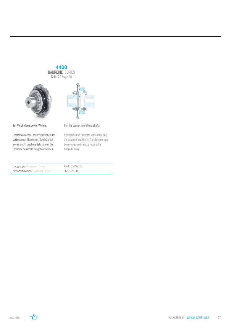
4400 BAUREIHE SERIES
Seite 20 Page 20
Zur Verbindung zweier Wellen.
Elementenwechsel ohne Verschieben der verbundenen Maschinen. Durch Zurück-ziehen des Flanschmantels können die Elemente senkrecht ausgebaut werden.
For the connection of two shafts.
Replacement of elements without moving the adjacent machinery. The elements can be removed vertically by moving the flanged casing.
Baugruppe Dimension Group K 4110 – K 6010
Nenndrehmoment Nominal Torque 3,25 – 26,00

08 VULKAN COUPLINGS VULKARDAN E
VULKARDAN E GEGLOCKTE ANWENDUNG AUSFÜHRUNG: GUMMI BELL HOUSING APPLICATION EXECUTION: RUBBER
01/2016
LEISTUNGSDATEN PERFORMANCE DATA
Kupplungstyp Type of Coupling TKN L3) M 3) C 3) TKmax1 TKmax2 ΔTmax TKW PKV50;1h nKmax ΔKr
2) Crdyn1) CTdyn
1) 2) ψ1) 2)
[kNm] SL SM SC [kNm] [kNm] [kNm] [kNm] [kW] [1/min] [mm] [kN/mm] [kNm/rad]nominal
nominal
Größe Baugruppe Nenndreh-moment
Anwendungs faktor Max. Dreh moment1
Max. Dreh moment2
Drehmoment Bereich
Wechsel-drehmoment
Verlust-leistung
Drehzahl Radialer Kupplungsversatz
Radiale Federsteife
DynamischeDrehfedersteife
Verhältnismäßige Dämpfung
Size Dimension Group
Nominal Torque
Duty-Class Factor Max. Torque1 Max. Torque2 Torque Range
Vibratory Torque
Power Loss
Rotational Speed
Radial Coupling Displacement
Radial Stiffness
Dynamic Tor-sional Stiffness
Relative Damping
K 1714 K 1710 0,21 1,00 0,89 0,77 0,24 0,58 0,17 0,06 0,147 7500 3,6 0,15 0,65 0,75K 1711 K 1710 0,21 1,00 0,89 0,77 0,24 0,58 0,26 0,06 0,147 7500 3,6 0,19 0,85 1,00K 1715 K 1710 0,26 1,00 0,89 0,77 0,30 0,72 0,34 0,06 0,147 7500 2,1 0,33 1,45 1,13K 1712 K 1710 0,26 1,00 0,89 0,77 0,30 0,72 0,42 0,06 0,147 7500 1,5 0,45 2,00 1,13K 2314 K 2310 0,72 1,00 0,89 0,77 0,83 1,98 0,54 0,22 0,173 6300 2,7 0,40 1,75 0,75K 2311 K 2310 0,72 1,00 0,89 0,77 0,83 1,98 0,82 0,22 0,173 6300 2,7 0,52 2,30 1,00K 2315 K 2310 0,88 1,00 0,89 0,77 1,02 2,45 1,09 0,22 0,173 6300 1,4 1,02 4,50 1,13K 2312 K 2310 0,88 1,00 0,89 0,77 1,02 2,45 1,35 0,22 0,173 6300 1,0 1,41 6,20 1,13K 2414 K 2410 0,82 1,00 0,89 0,77 0,95 2,27 0,62 0,25 0,248 6000 2,0 0,56 2,60 0,75K 2411 K 2410 0,82 1,00 0,89 0,77 0,95 2,27 0,94 0,25 0,248 6000 2,0 0,75 3,50 1,00K 2415 K 2410 1,04 1,00 0,89 0,77 1,20 2,88 1,25 0,25 0,248 6000 1,2 1,29 6,00 1,13K 2412 K 2410 1,04 1,00 0,89 0,77 1,20 2,88 1,55 0,25 0,248 6000 0,8 1,79 8,30 1,13K 2814 K 2810 1,30 1,00 0,89 0,77 1,50 3,60 0,98 0,40 0,287 5100 2,4 0,64 4,10 0,75K 2811 K 2810 1,30 1,00 0,89 0,77 1,50 3,60 1,49 0,40 0,287 5100 2,4 0,86 5,50 1,00K 2815 K 2810 1,63 1,00 0,89 0,77 1,88 4,50 1,97 0,40 0,287 5100 1,4 1,47 9,40 1,13K 2812 K 2810 1,63 1,00 0,89 0,77 1,88 4,50 2,45 0,40 0,287 5100 1,0 2,04 13,00 1,13K 3214 K 3210 1,63 1,00 0,89 0,77 1,88 4,50 1,14 0,50 0,259 4900 3,2 0,57 4,20 0,75K 3211 K 3210 1,63 1,00 0,89 0,77 1,88 4,50 1,74 0,50 0,259 4900 3,2 0,74 5,50 1,00K 3215 K 3210 1,95 1,00 0,89 0,77 2,25 5,40 2,30 0,50 0,259 4900 1,6 1,52 11,30 1,13K 3212 K 3210 1,95 1,00 0,89 0,77 2,25 5,40 2,86 0,50 0,259 4900 1,1 2,1 15,60 1,13K 3414 K 3410 2,08 1,00 0,89 0,77 2,40 5,76 1,58 0,64 0,333 4250 4,4 0,51 5,40 0,75K 3411 K 3410 2,08 1,00 0,89 0,77 2,40 5,76 2,41 0,64 0,333 4250 4,4 0,70 7,50 1,00K 3415 K 3410 2,60 1,00 0,89 0,77 3,00 7,20 3,19 0,64 0,333 4250 2,2 1,34 14,70 1,13K 3412 K 3410 2,60 1,00 0,89 0,77 3,00 7,20 3,96 0,64 0,333 4250 1,6 1,85 20,50 1,13K 4014 K 4010 3,25 1,00 0,89 0,77 3,75 9,00 2,45 1,00 0,337 3600 5,9 0,51 8,00 0,75K 4011 K 4010 3,25 1,00 0,89 0,77 3,75 9,00 3,72 1,00 0,337 3600 5,9 0,70 11,00 1,00K 4015 K 4010 4,10 1,00 0,89 0,77 4,73 11,34 4,93 1,00 0,337 3600 3,1 1,34 21,00 1,13K 4012 K 4010 4,10 1,00 0,89 0,77 4,73 11,34 6,12 1,00 0,337 3600 2,3 1,85 29,00 1,13K 4914 K 4910 5,20 1,00 0,89 0,77 6,00 14,40 4,31 1,60 0,440 2750 8,2 0,52 16,50 0,75K 4911 K 4910 5,20 1,00 0,89 0,77 6,00 14,40 6,55 1,60 0,440 2750 8,2 0,69 22,00 1,00K 4915 K 4910 6,50 1,00 0,89 0,77 7,50 18,00 8,68 1,60 0,440 2750 4,8 1,18 37,50 1,13K 4912 K 4910 6,50 1,00 0,89 0,77 7,50 18,00 10,79 1,60 0,440 2750 3,5 1,64 52,00 1,13
Siehe Erläuterung der Technischen Daten
1) VULKAN empfiehlt die zusätzliche Berücksichtigung von CTdyn warm (0,7), CTdyn la (1,35) und ψ warm (0,7)
für die Berechnung der Drehschwingungen in der Anlage.
2) Der Betriebszustand der Anlage kann eine Korrektur der gegebenen Werte notwendig machen.
Siehe Erläuterungen der Technischen Daten.
Bei mehrreihigen Kupplungen müssen bei der Drehschwingungsanalyse der Anlage die individuellen
Massenträgheitsmomente der Kupplung und die dynamischen Drehfedersteifen der einzelnen
Elemente berücksichtigt werden.
Durch die Eigenschaft des Werkstoffs Gummi sind Toleranzen der aufgeführten Daten für CTdyn von
+ 30 % bis 0 % für die 4er Elemente bzw. von +10 % bis - 20 % für die 1er und Silikon-Elemente bzw. von
+ 20 % bis - 10 % für die 5/2er Elemente möglich. Für ψ sind Toleranzen von 10 % bis -20 % möglich.
3) Bitte beachten Sie unsere Auslegungsbeispiele ab Seite 22.
See Explanation of the Technical Data
1) VULKAN recommends additionally taking into account CTdyn warm (0,7), CTdyn la (1,35) and ψ warm (0,7)
for calculating the torsional vibration in the system.
2) The operating state of the system can make it necessary to correct the values given.
See Technical Data notes.
With multi-row couplings, the individual moments of inertia of the coupling and the dynamic
torsional stiffnesses of the individual elements must be taken into account during the torsional
vibration analysis of the system.
The properties of the rubber mean that tolerances of + 30 % to 0 % for the 4 elements and + 10 % to
- 20 % for the 1 and silicone elements, and + 20 % to -10 % for the 5/2 elements with respect to the
data given for CTdyn are possible. For ψ tolerances are possible from 10 % to -20 %.
3) Please consider our sample selection on page 22 ff.
09VULKAN COUPLINGSVULKARDAN E
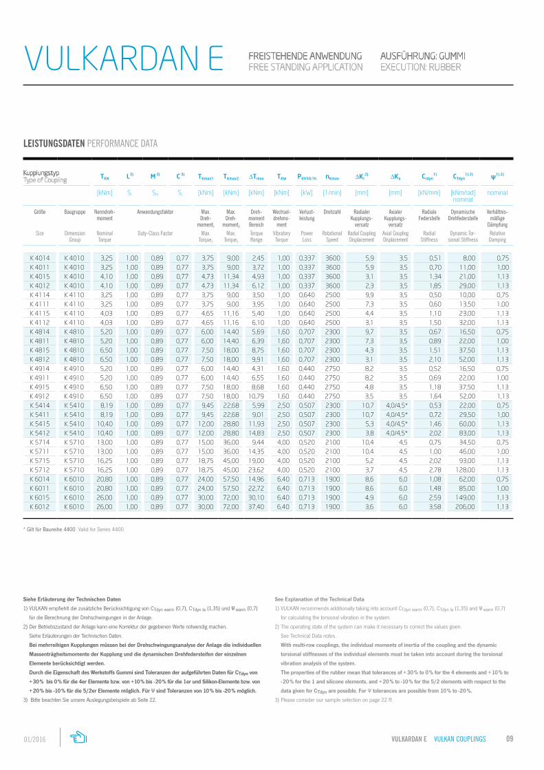
VULKARDAN E FREISTEHENDE ANWENDUNG AUSFÜHRUNG: GUMMI FREE STANDING APPLICATION EXECUTION: RUBBER
01/2016
Siehe Erläuterung der Technischen Daten
1) VULKAN empfiehlt die zusätzliche Berücksichtigung von CTdyn warm (0,7), CTdyn la (1,35) und ψ warm (0,7)
für die Berechnung der Drehschwingungen in der Anlage.
2) Der Betriebszustand der Anlage kann eine Korrektur der gegebenen Werte notwendig machen.
Siehe Erläuterungen der Technischen Daten.
Bei mehrreihigen Kupplungen müssen bei der Drehschwingungsanalyse der Anlage die individuellen
Massenträgheitsmomente der Kupplung und die dynamischen Drehfedersteifen der einzelnen
Elemente berücksichtigt werden.
Durch die Eigenschaft des Werkstoffs Gummi sind Toleranzen der aufgeführten Daten für CTdyn von
+ 30 % bis 0 % für die 4er Elemente bzw. von +10 % bis - 20 % für die 1er und Silikon-Elemente bzw. von
+ 20 % bis - 10 % für die 5/2er Elemente möglich. Für ψ sind Toleranzen von 10 % bis -20 % möglich.
3) Bitte beachten Sie unsere Auslegungsbeispiele ab Seite 22.
See Explanation of the Technical Data
1) VULKAN recommends additionally taking into account CTdyn warm (0,7), CTdyn la (1,35) and ψ warm (0,7)
for calculating the torsional vibration in the system.
2) The operating state of the system can make it necessary to correct the values given.
See Technical Data notes.
With multi-row couplings, the individual moments of inertia of the coupling and the dynamic
torsional stiffnesses of the individual elements must be taken into account during the torsional
vibration analysis of the system.
The properties of the rubber mean that tolerances of + 30 % to 0 % for the 4 elements and + 10 % to
- 20 % for the 1 and silicone elements, and + 20 % to -10 % for the 5/2 elements with respect to the
data given for CTdyn are possible. For ψ tolerances are possible from 10 % to -20 %.
3) Please consider our sample selection on page 22 ff.
* Gilt für Baureihe 4400 Valid for Series 4400
LEISTUNGSDATEN PERFORMANCE DATA
Kupplungstyp Type of Coupling TKN L3) M 3) C 3) TKmax1 TKmax2 ΔTmax TKW PKV50;1h nKmax ΔKr
2) ΔKa Crdyn1) CTdyn
1) 2) ψ1) 2)
[kNm] SL SM SC [kNm] [kNm] [kNm] [kNm] [kW] [1/min] [mm] [mm] [kN/mm] [kNm/rad]nominal
nominal
Größe Baugruppe Nenndreh-moment
Anwendungs faktor Max. Dreh-
moment1
Max. Dreh-
moment2
Dreh-moment Bereich
Wechsel-drehmo-
ment
Verlust-leistung
Drehzahl Radialer Kupplungs-
versatz
AxialerKupplungs-
versatz
Radiale Federsteife
DynamischeDrehfedersteife
Verhältnis-mäßige
DämpfungSize Dimension
GroupNominal Torque
Duty-Class Factor Max. Torque1
Max. Torque2
Torque Range
Vibratory Torque
Power Loss
Rotational Speed
Radial Coupling Displacement
Axial Coupling Displacement
Radial Stiffness
Dynamic Tor-sional Stiffness
Relative Damping
K 4014 K 4010 3,25 1,00 0,89 0,77 3,75 9,00 2,45 1,00 0,337 3600 5,9 3,5 0,51 8,00 0,75K 4011 K 4010 3,25 1,00 0,89 0,77 3,75 9,00 3,72 1,00 0,337 3600 5,9 3,5 0,70 11,00 1,00K 4015 K 4010 4,10 1,00 0,89 0,77 4,73 11,34 4,93 1,00 0,337 3600 3,1 3,5 1,34 21,00 1,13K 4012 K 4010 4,10 1,00 0,89 0,77 4,73 11,34 6,12 1,00 0,337 3600 2,3 3,5 1,85 29,00 1,13K 4114 K 4110 3,25 1,00 0,89 0,77 3,75 9,00 3,50 1,00 0,640 2500 9,9 3,5 0,50 10,00 0,75K 4111 K 4110 3,25 1,00 0,89 0,77 3,75 9,00 3,95 1,00 0,640 2500 7,3 3,5 0,60 13,50 1,00K 4115 K 4110 4,03 1,00 0,89 0,77 4,65 11,16 5,40 1,00 0,640 2500 4,4 3,5 1,10 23,00 1,13K 4112 K 4110 4,03 1,00 0,89 0,77 4,65 11,16 6,10 1,00 0,640 2500 3,1 3,5 1,50 32,00 1,13K 4814 K 4810 5,20 1,00 0,89 0,77 6,00 14,40 5,69 1,60 0,707 2300 9,7 3,5 0,67 16,50 0,75K 4811 K 4810 5,20 1,00 0,89 0,77 6,00 14,40 6,39 1,60 0,707 2300 7,3 3,5 0,89 22,00 1,00K 4815 K 4810 6,50 1,00 0,89 0,77 7,50 18,00 8,75 1,60 0,707 2300 4,3 3,5 1,51 37,50 1,13K 4812 K 4810 6,50 1,00 0,89 0,77 7,50 18,00 9,91 1,60 0,707 2300 3,1 3,5 2,10 52,00 1,13K 4914 K 4910 5,20 1,00 0,89 0,77 6,00 14,40 4,31 1,60 0,440 2750 8,2 3,5 0,52 16,50 0,75K 4911 K 4910 5,20 1,00 0,89 0,77 6,00 14,40 6,55 1,60 0,440 2750 8,2 3,5 0,69 22,00 1,00K 4915 K 4910 6,50 1,00 0,89 0,77 7,50 18,00 8,68 1,60 0,440 2750 4,8 3,5 1,18 37,50 1,13K 4912 K 4910 6,50 1,00 0,89 0,77 7,50 18,00 10,79 1,60 0,440 2750 3,5 3,5 1,64 52,00 1,13K 5414 K 5410 8,19 1,00 0,89 0,77 9,45 22,68 5,99 2,50 0,507 2300 10,7 4,0/4,5* 0,53 22,00 0,75K 5411 K 5410 8,19 1,00 0,89 0,77 9,45 22,68 9,01 2,50 0,507 2300 10,7 4,0/4,5* 0,72 29,50 1,00K 5415 K 5410 10,40 1,00 0,89 0,77 12,00 28,80 11,93 2,50 0,507 2300 5,3 4,0/4,5* 1,46 60,00 1,13K 5412 K 5410 10,40 1,00 0,89 0,77 12,00 28,80 14,83 2,50 0,507 2300 3,8 4,0/4,5* 2,02 83,00 1,13K 5714 K 5710 13,00 1,00 0,89 0,77 15,00 36,00 9,44 4,00 0,520 2100 10,4 4,5 0,75 34,50 0,75K 5711 K 5710 13,00 1,00 0,89 0,77 15,00 36,00 14,35 4,00 0,520 2100 10,4 4,5 1,00 46,00 1,00K 5715 K 5710 16,25 1,00 0,89 0,77 18,75 45,00 19,00 4,00 0,520 2100 5,2 4,5 2,02 93,00 1,13K 5712 K 5710 16,25 1,00 0,89 0,77 18,75 45,00 23,62 4,00 0,520 2100 3,7 4,5 2,78 128,00 1,13K 6014 K 6010 20,80 1,00 0,89 0,77 24,00 57,50 14,96 6,40 0,713 1900 8,6 6,0 1,08 62,00 0,75K 6011 K 6010 20,80 1,00 0,89 0,77 24,00 57,50 22,72 6,40 0,713 1900 8,6 6,0 1,48 85,00 1,00K 6015 K 6010 26,00 1,00 0,89 0,77 30,00 72,00 30,10 6,40 0,713 1900 4,9 6,0 2,59 149,00 1,13K 6012 K 6010 26,00 1,00 0,89 0,77 30,00 72,00 37,40 6,40 0,713 1900 3,6 6,0 3,58 206,00 1,13

10 VULKAN COUPLINGS VULKARDAN E
VULKARDAN E GEGLOCKTE ANWENDUNG AUSFÜHRUNG: SILIKON BELL HOUSING APPLICATION EXECUTION: SILICONE
01/2016
LEISTUNGSDATEN PERFORMANCE DATA
Kupplungstyp Type of Coupling TKN L3) M 3) C 3) TKmax1 TKmax2 ΔTmax TKW PKV50;1h nKmax ΔKr
2) Crdyn1) CTdyn
1) 2) ψ1) 2)
[kNm] SL SM SC [kNm] [kNm] [kNm] [kNm] [kW] [1/min] [mm] [kN/mm]
[kNm/rad] nominal nominal10 % TkN 25 % TkN 50 % TkN 75 % TkN 100 % TkN
Größe Baugruppe Nenn-dreh-
moment
Anwen-dung
Anwendungs faktor Max. Dreh-
moment1
Max. Dreh-
moment2
Dreh-moment Bereich
Wechsel-dreh-
moment
Verlust-leistung
Drehzahl Radialer Kupplungs-
versatz
Radiale Feder-steife
Dynamische Drehfedersteife Verhält-nismäßige Dämpfung
Size Dimension Group
Nominal Torque
Duty Duty-Class Factor Max. Torque1
Max. Torque2
Torque Range
Vibratory Torque
Power Loss
Rotational Speed
Radial Coupling
Displacement
Radial Stiffness
Dynamic Torsional Stiffness Relative Damping
K 2811 K 2810 1,63 L 1,00 – – 1,75 2,50 1,54 0,40 0,450 5100 1,9 1,10 4,4 4,5 5,8 10,1 18,8 1,13K 2811 K 2810 1,63 M – 0,77 – 1,75 2,50 1,54 0,40 0,450 5100 1,9 1,10 4,4 4,6 4,7 7,0 10,5 1,13K 2811 K 2810 1,63 C – – 0,62 1,75 2,50 1,54 0,40 0,450 5100 1,9 1,10 4,4 4,4 4,6 5,5 7,4 1,13K 3411 K 3410 2,60 L 1,00 – – 2,80 4,00 2,50 0,64 0,550 4250 2,8 1,12 6,9 7,1 10,1 17,1 28,9 1,13K 3411 K 3410 2,60 M – 0,77 – 2,80 4,00 2,50 0,64 0,550 4250 2,8 1,12 6,9 7,0 8,1 11,8 17,6 1,13K 3411 K 3410 2,60 C – – 0,62 2,80 4,00 2,50 0,64 0,550 4250 2,8 1,12 6,9 6,9 7,5 9,4 12,8 1,13K 4011 K 4010 4,10 L 1,00 – – 4,41 6,30 3,86 1,00 0,550 3600 3,3 1,27 10,2 11,3 17,1 29,5 46,7 1,13K 4011 K 4010 4,10 M – 0,77 – 4,41 6,30 3,86 1,00 0,550 3600 3,3 1,27 10,0 11,0 13,2 20,0 32,0 1,13K 4011 K 4010 4,10 C – – 0,62 4,41 6,30 3,86 1,00 0,550 3600 3,3 1,27 9,9 10,1 11,6 15,7 22,2 1,13K 4911 K 4910 6,50 L 1,00 – – 7,00 10,00 6,80 1,60 0,733 2750 5,3 1,07 19,5 20,9 28,1 46,4 81,9 1,13K 4911 K 4910 6,50 M – 0,77 – 7,00 10,00 6,80 1,60 0,733 2750 5,3 1,07 19,4 19,9 23,1 33,9 47,0 1,13K 4911 K 4910 6,50 C – – 0,62 7,00 10,00 6,80 1,60 0,733 2750 5,3 1,07 19,0 19,8 21,9 26,4 34,8 1,13
Siehe Erläuterung der Technischen Daten
1) VULKAN empfiehlt die zusätzliche Berücksichtigung von CTdyn warm (0,7), CTdyn la (1,35) und ψ warm (0,7)
für die Berechnung der Drehschwingungen in der Anlage.
2) Der Betriebszustand der Anlage kann eine Korrektur der gegebenen Werte notwendig machen.
Siehe Erläuterungen der Technischen Daten.
Bei mehrreihigen Kupplungen müssen bei der Drehschwingungsanalyse der Anlage die individuellen
Massenträgheitsmomente der Kupplung und die dynamischen Drehfedersteifen der einzelnen
Elemente berücksichtigt werden.
Durch die Eigenschaft des Werkstoffs Gummi sind Toleranzen der aufgeführten Daten für CTdyn von
+ 30 % bis 0 % für die 4er Elemente bzw. von +10 % bis - 20 % für die 1er und Silikon-Elemente bzw. von
+ 20 % bis - 10 % für die 5/2er Elemente möglich. Für ψ sind Toleranzen von 10 % bis -20 % möglich.
3) Bitte beachten Sie unsere Auslegungsbeispiele ab Seite 22.
See Explanation of the Technical Data
1) VULKAN recommends additionally taking into account CTdyn warm (0,7), CTdyn la (1,35) and ψ warm (0,7)
for calculating the torsional vibration in the system.
2) The operating state of the system can make it necessary to correct the values given.
See Technical Data notes.
With multi-row couplings, the individual moments of inertia of the coupling and the dynamic
torsional stiffnesses of the individual elements must be taken into account during the torsional
vibration analysis of the system.
The properties of the rubber mean that tolerances of + 30 % to 0 % for the 4 elements and + 10 % to
- 20 % for the 1 and silicone elements, and + 20 % to -10 % for the 5/2 elements with respect to the
data given for CTdyn are possible. For ψ tolerances are possible from 10 % to -20 %.
3) Please consider our sample selection on page 22 ff.
11VULKAN COUPLINGSVULKARDAN E01/2016
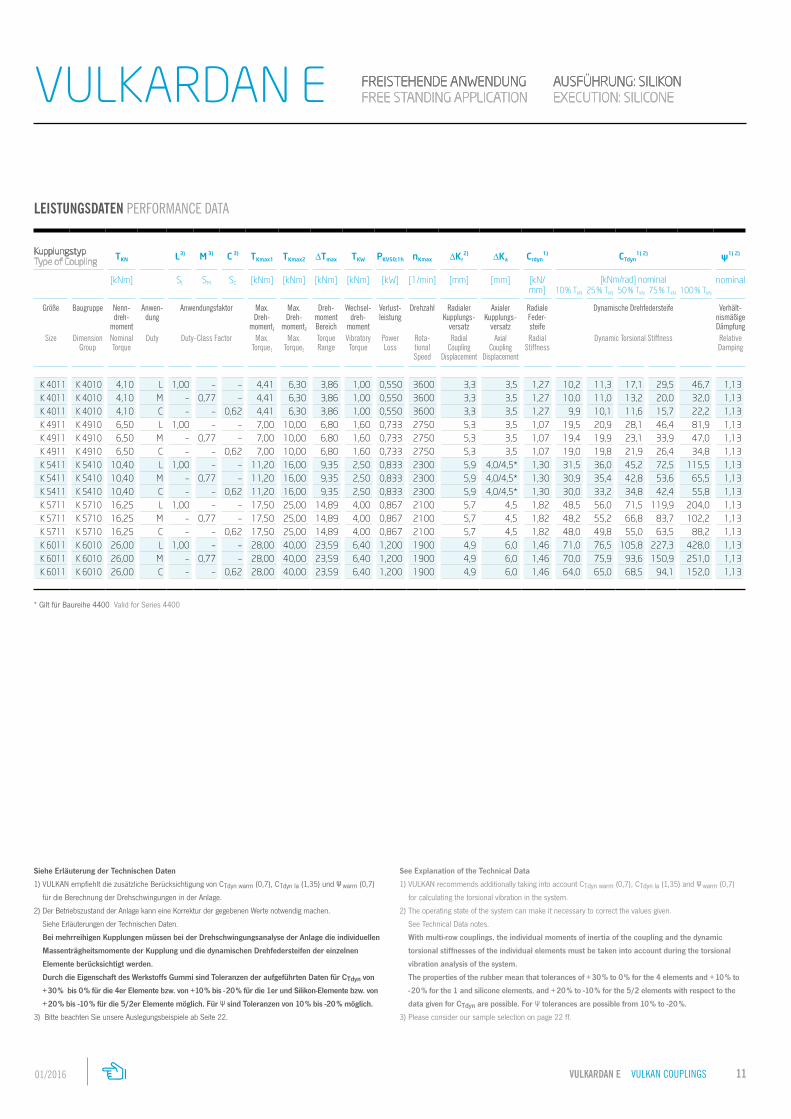
LEISTUNGSDATEN PERFORMANCE DATA
Kupplungstyp Type of Coupling TKN L3) M 3) C 3) TKmax1 TKmax2 ΔTmax TKW PKV50;1h nKmax ΔKr
2) ΔKa Crdyn1) CTdyn
1) 2) ψ1) 2)
[kNm] SL SM SC [kNm] [kNm] [kNm] [kNm] [kW] [1/min] [mm] [mm] [kN/mm]
[kNm/rad] nominal nominal10 % TkN 25 % TkN 50 % TkN 75 % TkN 100 % TkN
Größe Baugruppe Nenn-dreh-
moment
Anwen-dung
Anwendungs faktor Max. Dreh-
moment1
Max. Dreh-
moment2
Dreh-moment Bereich
Wechsel-dreh-
moment
Verlust-leistung
Drehzahl Radialer Kupplungs-
versatz
AxialerKupplungs-
versatz
Radiale Feder-steife
Dynamische Drehfedersteife Verhält-nismäßige Dämpfung
Size Dimension Group
Nominal Torque
Duty Duty-Class Factor Max. Torque1
Max. Torque2
Torque Range
Vibratory Torque
Power Loss
Rota-tional Speed
Radial Coupling
Displacement
AxialCoupling
Displacement
Radial Stiffness
Dynamic Torsional Stiffness Relative Damping
K 4011 K 4010 4,10 L 1,00 – – 4,41 6,30 3,86 1,00 0,550 3600 3,3 3,5 1,27 10,2 11,3 17,1 29,5 46,7 1,13K 4011 K 4010 4,10 M – 0,77 – 4,41 6,30 3,86 1,00 0,550 3600 3,3 3,5 1,27 10,0 11,0 13,2 20,0 32,0 1,13K 4011 K 4010 4,10 C – – 0,62 4,41 6,30 3,86 1,00 0,550 3600 3,3 3,5 1,27 9,9 10,1 11,6 15,7 22,2 1,13K 4911 K 4910 6,50 L 1,00 – – 7,00 10,00 6,80 1,60 0,733 2750 5,3 3,5 1,07 19,5 20,9 28,1 46,4 81,9 1,13K 4911 K 4910 6,50 M – 0,77 – 7,00 10,00 6,80 1,60 0,733 2750 5,3 3,5 1,07 19,4 19,9 23,1 33,9 47,0 1,13K 4911 K 4910 6,50 C – – 0,62 7,00 10,00 6,80 1,60 0,733 2750 5,3 3,5 1,07 19,0 19,8 21,9 26,4 34,8 1,13K 5411 K 5410 10,40 L 1,00 – – 11,20 16,00 9,35 2,50 0,833 2300 5,9 4,0/4,5* 1,30 31,5 36,0 45,2 72,5 115,5 1,13K 5411 K 5410 10,40 M – 0,77 – 11,20 16,00 9,35 2,50 0,833 2300 5,9 4,0/4,5* 1,30 30,9 35,4 42,8 53,6 65,5 1,13K 5411 K 5410 10,40 C – – 0,62 11,20 16,00 9,35 2,50 0,833 2300 5,9 4,0/4,5* 1,30 30,0 33,2 34,8 42,4 55,8 1,13K 5711 K 5710 16,25 L 1,00 – – 17,50 25,00 14,89 4,00 0,867 2100 5,7 4,5 1,82 48,5 56,0 71,5 119,9 204,0 1,13K 5711 K 5710 16,25 M – 0,77 – 17,50 25,00 14,89 4,00 0,867 2100 5,7 4,5 1,82 48,2 55,2 66,8 83,7 102,2 1,13K 5711 K 5710 16,25 C – – 0,62 17,50 25,00 14,89 4,00 0,867 2100 5,7 4,5 1,82 48,0 49,8 55,0 63,5 88,2 1,13K 6011 K 6010 26,00 L 1,00 – – 28,00 40,00 23,59 6,40 1,200 1900 4,9 6,0 1,46 71,0 76,5 105,8 227,3 428,0 1,13K 6011 K 6010 26,00 M – 0,77 – 28,00 40,00 23,59 6,40 1,200 1900 4,9 6,0 1,46 70,0 75,9 93,6 150,9 251,0 1,13K 6011 K 6010 26,00 C – – 0,62 28,00 40,00 23,59 6,40 1,200 1900 4,9 6,0 1,46 64,0 65,0 68,5 94,1 152,0 1,13
VULKARDAN E FREISTEHENDE ANWENDUNG AUSFÜHRUNG: SILIKON FREE STANDING APPLICATION EXECUTION: SILICONE
Siehe Erläuterung der Technischen Daten
1) VULKAN empfiehlt die zusätzliche Berücksichtigung von CTdyn warm (0,7), CTdyn la (1,35) und ψ warm (0,7)
für die Berechnung der Drehschwingungen in der Anlage.
2) Der Betriebszustand der Anlage kann eine Korrektur der gegebenen Werte notwendig machen.
Siehe Erläuterungen der Technischen Daten.
Bei mehrreihigen Kupplungen müssen bei der Drehschwingungsanalyse der Anlage die individuellen
Massenträgheitsmomente der Kupplung und die dynamischen Drehfedersteifen der einzelnen
Elemente berücksichtigt werden.
Durch die Eigenschaft des Werkstoffs Gummi sind Toleranzen der aufgeführten Daten für CTdyn von
+ 30 % bis 0 % für die 4er Elemente bzw. von +10 % bis - 20 % für die 1er und Silikon-Elemente bzw. von
+ 20 % bis - 10 % für die 5/2er Elemente möglich. Für ψ sind Toleranzen von 10 % bis -20 % möglich.
3) Bitte beachten Sie unsere Auslegungsbeispiele ab Seite 22.
See Explanation of the Technical Data
1) VULKAN recommends additionally taking into account CTdyn warm (0,7), CTdyn la (1,35) and ψ warm (0,7)
for calculating the torsional vibration in the system.
2) The operating state of the system can make it necessary to correct the values given.
See Technical Data notes.
With multi-row couplings, the individual moments of inertia of the coupling and the dynamic
torsional stiffnesses of the individual elements must be taken into account during the torsional
vibration analysis of the system.
The properties of the rubber mean that tolerances of + 30 % to 0 % for the 4 elements and + 10 % to
- 20 % for the 1 and silicone elements, and + 20 % to -10 % for the 5/2 elements with respect to the
data given for CTdyn are possible. For ψ tolerances are possible from 10 % to -20 %.
3) Please consider our sample selection on page 22 ff.
* Gilt für Baureihe 4400 Valid for Series 4400
12 VULKAN COUPLINGS VULKARDAN E
L7
L1
L5
L11
L2
Ø D3
min.
Ø D3
max
.
Ø D1
Ø D1
6
Ø D1
1
Ø D1
5 T
1
Ø D1
4 +0 -0
.127
S2
M2
S1
M1
KKE401FC00A
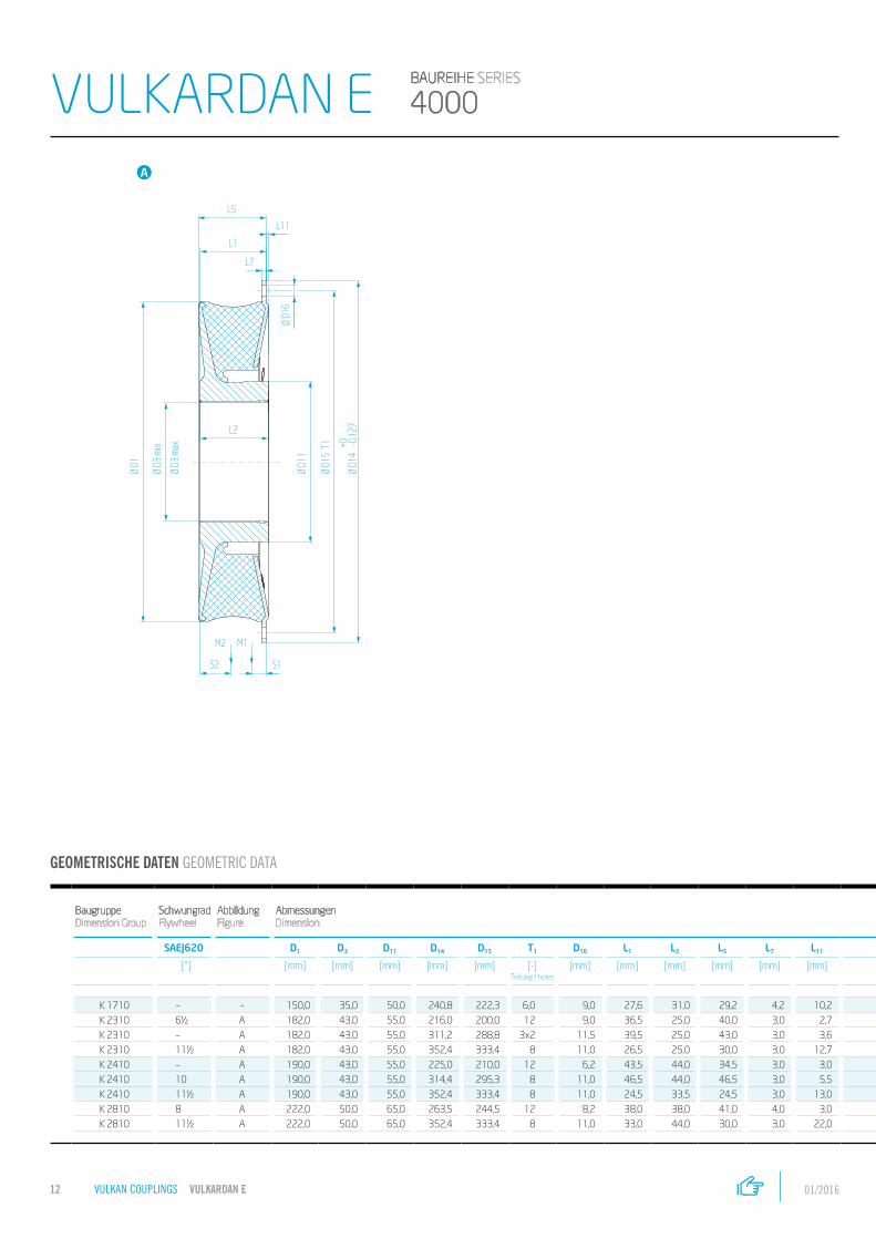
VULKARDAN E 4000BAUREIHE SERIES
01/2016
GEOMETRISCHE DATEN GEOMETRIC DATA
Baugruppe Schwungrad Abbildung Abmessungen Massenträgheitsmomente Masse Schwerpunktsabstand AnmerkungenDimension Group Flywheel Figure Dimension Mass moments of inertia Mass Distance to center of gravity Notes
SAEJ620 D1 D3 D11 D14 D15 T1 D16 L1 L2 L5 L7 L11 J1 J2 M1 M2 S1 S2
[“] [mm] [mm] [mm] [mm] [mm] [-] [mm] [mm] [mm] [mm] [mm] [mm] [kgm²] [kgm²] [kg] [kg] [mm] [mm]Teilung / holes
K 1710 – – 150,0 35,0 50,0 240,8 222,3 6,0 9,0 27,6 31,0 29,2 4,2 10,2 0,006 0,002 1,3 1,1 2,1 8,4
K 2310 6½ A 182,0 43,0 55,0 216,0 200,0 12 9,0 36,5 25,0 40,0 3,0 2,7 0,010 0,010 1,1 1,7 – –
K 2310 – A 182,0 43,0 55,0 311,2 288,8 3x2 11,5 39,5 25,0 43,0 3,0 3,6 0,040 0,010 2,8 1,7 – –
K 2310 11½ A 182,0 43,0 55,0 352,4 333,4 8 11,0 26,5 25,0 30,0 3,0 12,7 0,040 0,010 3,1 1,7 3,4 5,4
K 2410 – A 190,0 43,0 55,0 225,0 210,0 12 6,2 43,5 44,0 34,5 3,0 3,0 0,010 0,010 1,1 2,1 3,6 18,3
K 2410 10 A 190,0 43,0 55,0 314,4 295,3 8 11,0 46,5 44,0 46,5 3,0 5,5 0,030 0,010 2,5 2,1 4,3 18,3
K 2410 11½ A 190,0 43,0 55,0 352,4 333,4 8 11,0 24,5 33,5 24,5 3,0 13,0 0,040 0,010 2,7 1,9 – –
K 2810 8 A 222,0 50,0 65,0 263,5 244,5 12 8,2 38,0 38,0 41,0 4,0 3,0 0,030 0,020 2,2 3,2 – –
K 2810 11½ A 222,0 50,0 65,0 352,4 333,4 8 11,0 33,0 44,0 30,0 3,0 22,0 0,070 0,040 6,8 5,6 2,7 15,9

13VULKAN COUPLINGSVULKARDAN E01/2016
GEOMETRISCHE DATEN GEOMETRIC DATA
Baugruppe Schwungrad Abbildung Abmessungen Massenträgheitsmomente Masse Schwerpunktsabstand AnmerkungenDimension Group Flywheel Figure Dimension Mass moments of inertia Mass Distance to center of gravity Notes
SAEJ620 D1 D3 D11 D14 D15 T1 D16 L1 L2 L5 L7 L11 J1 J2 M1 M2 S1 S2
[“] [mm] [mm] [mm] [mm] [mm] [-] [mm] [mm] [mm] [mm] [mm] [mm] [kgm²] [kgm²] [kg] [kg] [mm] [mm]Teilung / holes
K 1710 – – 150,0 35,0 50,0 240,8 222,3 6,0 9,0 27,6 31,0 29,2 4,2 10,2 0,006 0,002 1,3 1,1 2,1 8,4
K 2310 6½ A 182,0 43,0 55,0 216,0 200,0 12 9,0 36,5 25,0 40,0 3,0 2,7 0,010 0,010 1,1 1,7 – –
K 2310 – A 182,0 43,0 55,0 311,2 288,8 3x2 11,5 39,5 25,0 43,0 3,0 3,6 0,040 0,010 2,8 1,7 – –
K 2310 11½ A 182,0 43,0 55,0 352,4 333,4 8 11,0 26,5 25,0 30,0 3,0 12,7 0,040 0,010 3,1 1,7 3,4 5,4
K 2410 – A 190,0 43,0 55,0 225,0 210,0 12 6,2 43,5 44,0 34,5 3,0 3,0 0,010 0,010 1,1 2,1 3,6 18,3
K 2410 10 A 190,0 43,0 55,0 314,4 295,3 8 11,0 46,5 44,0 46,5 3,0 5,5 0,030 0,010 2,5 2,1 4,3 18,3
K 2410 11½ A 190,0 43,0 55,0 352,4 333,4 8 11,0 24,5 33,5 24,5 3,0 13,0 0,040 0,010 2,7 1,9 – –
K 2810 8 A 222,0 50,0 65,0 263,5 244,5 12 8,2 38,0 38,0 41,0 4,0 3,0 0,030 0,020 2,2 3,2 – –
K 2810 11½ A 222,0 50,0 65,0 352,4 333,4 8 11,0 33,0 44,0 30,0 3,0 22,0 0,070 0,040 6,8 5,6 2,7 15,9

14 VULKAN COUPLINGS VULKARDAN E
L7
Ø D1
5 T1
L1
L5
L11
Ø D1
6
Ø D1
4 +0 -0
.127
Ø D1
Ø
D3 m
in.
Ø D3
max
.
S2
M2
S1
M1
Ø D1
1
L2
KKE491GD01A
VULKARDAN E 4001 mit Durchdrehsicherung* with torsional limit device*
BAUREIHE SERIES
01/2016
GEOMETRISCHE DATEN GEOMETRIC DATA
Baugruppe Schwungrad Abbildung Abmessungen Massenträgheitsmomente Masse Schwerpunktsabstand AnmerkungenDimension Group Flywheel Figure Dimension Mass moments of inertia Mass Distance to center of gravity Notes
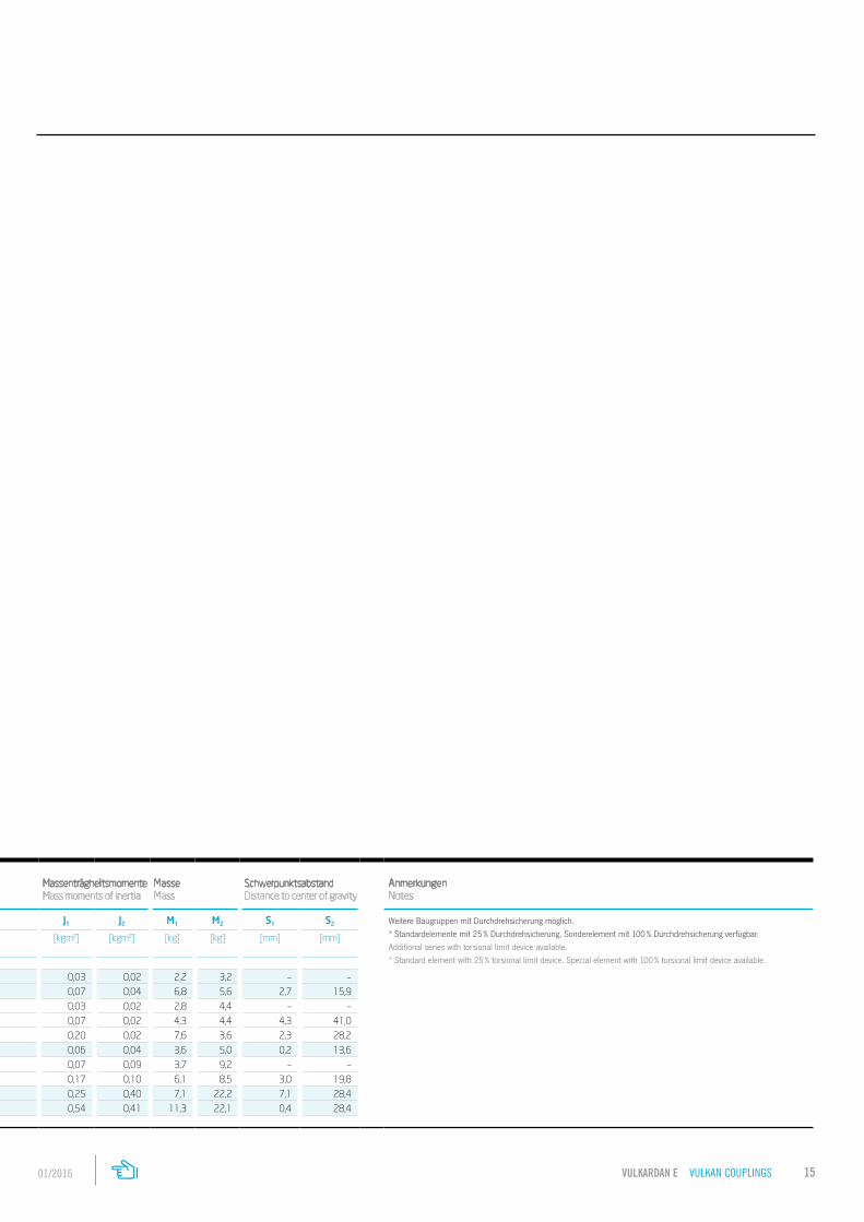
SAEJ620 D1 D3 D11 D14 D15 T1 D16 L1 L2 L5 L7 L11 J1 J2 M1 M2 S1 S2 Weitere Baugruppen mit Durchdrehsicherung möglich.* Standardelemente mit 25 % Durchdrehsicherung. Sonderelement mit 100 % Durchdrehsicherung verfügbar.Additional series with torsional limit device available.* Standard element with 25 % torsional limit device. Special element with 100 % torsional limit device available.
[“] [mm] [mm] [mm] [mm] [mm] [-] [mm] [mm] [mm] [mm] [mm] [mm] [kgm²] [kgm²] [kg] [kg] [mm] [mm]Teilung / holes
K 2810 8 A 222,0 50,0 65,0 263,5 244,5 12 8,2 38,0 38,0 41,0 4,0 3,0 0,03 0,02 2,2 3,2 – –
K 2810 11½ A 222,0 50,0 65,0 352,4 333,4 8 11,0 33,0 44,0 30,0 3,0 22,0 0,07 0,04 6,8 5,6 2,7 15,9
K 3210 – A – 58,0 75,0 280,0 260,0 12 8,2 74,0 70,0 47,0 4,0 2,8 0,03 0,02 2,8 4,4 – –
K 3210 11½ A 234,0 58,0 75,0 352,4 333,4 8 11,0 81,0 83,0 54,0 4,0 2,0 0,07 0,02 4,3 4,4 4,3 41,0
K 3210 14 A 234,0 58,0 75,0 466,7 438,2 8 14,0 60,0 62,0 43,0 5,0 2,0 0,20 0,02 7,6 3,6 2,3 28,2
K 3410 11½ A 266,0 84,0 110,0 352,4 333,4 8 11,0 45,0 53,0 47,0 4,0 10,8 0,06 0,04 3,6 5,0 0,2 13,6
K 4010 11½ A 312,0 120,0 157,0 352,4 333,4 8 11,0 64,0 66,0 66,0 4,0 2,8 0,07 0,09 3,7 9,2 – –
K 4010 14 A 312,0 120,0 157,0 466,7 438,2 8 14,0 50,0 66,0 52,0 4,0 16,7 0,17 0,10 6,1 8,5 3,0 19,8
K 4910 14 A 407,0 200,0 265,0 466,7 438,2 8 14,0 69,0 77,0 76,0 6,0 4,7 0,25 0,40 7,1 22,2 7,1 28,4
K 4910 18 A 407,0 200,0 265,0 571,5 542,9 12 17,0 59,5 77,0 66,5 6,0 14,2 0,54 0,41 11,3 22,1 0,4 28,4
15VULKAN COUPLINGSVULKARDAN E01/2016
GEOMETRISCHE DATEN GEOMETRIC DATA
Baugruppe Schwungrad Abbildung Abmessungen Massenträgheitsmomente Masse Schwerpunktsabstand AnmerkungenDimension Group Flywheel Figure Dimension Mass moments of inertia Mass Distance to center of gravity Notes
SAEJ620 D1 D3 D11 D14 D15 T1 D16 L1 L2 L5 L7 L11 J1 J2 M1 M2 S1 S2 Weitere Baugruppen mit Durchdrehsicherung möglich.* Standardelemente mit 25 % Durchdrehsicherung. Sonderelement mit 100 % Durchdrehsicherung verfügbar.Additional series with torsional limit device available.* Standard element with 25 % torsional limit device. Special element with 100 % torsional limit device available.
[“] [mm] [mm] [mm] [mm] [mm] [-] [mm] [mm] [mm] [mm] [mm] [mm] [kgm²] [kgm²] [kg] [kg] [mm] [mm]Teilung / holes
K 2810 8 A 222,0 50,0 65,0 263,5 244,5 12 8,2 38,0 38,0 41,0 4,0 3,0 0,03 0,02 2,2 3,2 – –
K 2810 11½ A 222,0 50,0 65,0 352,4 333,4 8 11,0 33,0 44,0 30,0 3,0 22,0 0,07 0,04 6,8 5,6 2,7 15,9
K 3210 – A – 58,0 75,0 280,0 260,0 12 8,2 74,0 70,0 47,0 4,0 2,8 0,03 0,02 2,8 4,4 – –
K 3210 11½ A 234,0 58,0 75,0 352,4 333,4 8 11,0 81,0 83,0 54,0 4,0 2,0 0,07 0,02 4,3 4,4 4,3 41,0
K 3210 14 A 234,0 58,0 75,0 466,7 438,2 8 14,0 60,0 62,0 43,0 5,0 2,0 0,20 0,02 7,6 3,6 2,3 28,2
K 3410 11½ A 266,0 84,0 110,0 352,4 333,4 8 11,0 45,0 53,0 47,0 4,0 10,8 0,06 0,04 3,6 5,0 0,2 13,6
K 4010 11½ A 312,0 120,0 157,0 352,4 333,4 8 11,0 64,0 66,0 66,0 4,0 2,8 0,07 0,09 3,7 9,2 – –
K 4010 14 A 312,0 120,0 157,0 466,7 438,2 8 14,0 50,0 66,0 52,0 4,0 16,7 0,17 0,10 6,1 8,5 3,0 19,8
K 4910 14 A 407,0 200,0 265,0 466,7 438,2 8 14,0 69,0 77,0 76,0 6,0 4,7 0,25 0,40 7,1 22,2 7,1 28,4
K 4910 18 A 407,0 200,0 265,0 571,5 542,9 12 17,0 59,5 77,0 66,5 6,0 14,2 0,54 0,41 11,3 22,1 0,4 28,4
16 VULKAN COUPLINGS VULKARDAN E
Ø D2
L11
Ø D3
min.
Ø D3
max
.
Ø D1
6
Ø D1
5 T
1
S2
M2
S1
M1
L2
L1
Ø D1
F1x45~
L7
Ø D1
4 +0 -0
.127
KKE401IC00
L7
F1x45 ~
L2Ø D1
Ø D2
Ø D3
min.
Ø D3
max
.
Ø D1
6
Ø D1
5 T
1
Ø D1
4 +0 -0
.127
S2M2
S1M1
L1
KKE601IG00
B
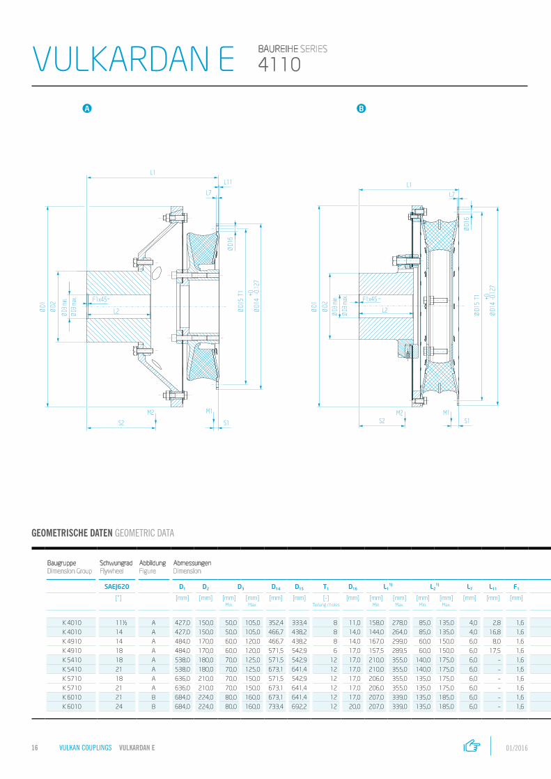
VULKARDAN E 4110BAUREIHE SERIES
01/2016
A
GEOMETRISCHE DATEN GEOMETRIC DATA
Baugruppe Schwungrad Abbildung Abmessungen Massenträgheitsmomente Masse Schwerpunktsabstand AnmerkungenDimension Group Flywheel Figure Dimension Mass moments of inertia Mass Distance to center of gravity Notes
SAEJ620 D1 D2 D3 D14 D15 T1 D16 L11) L2
1) L7 L11 F1 J1 J2 M1 M2 S1 S2 Alle Massen, Schwerpunkte und Massenträgheitsmomente beziehen sich auf min. Nabendurchmesser bei max. Nabenlänge1) L1 und L2 beschreiben Standardsituationen und können im Anwendungsfall angepasst werden. Die Auslegung der Naben-
länge erfolgt in Abhängigkeit des Anlagen momentes TN und muss anwendungsbezogen berechnet werden. Besuchen Sie hierfür das VULKAN Engeneering Portal auf unserer Homepage www.vulkan.com oder kontaktieren Sie die VULKAN Vertretung in ihrer Nähe.
All masses, focal points and mass moments of inertia refer to min. hub diameter at max. hub length.1) L1 and L2 describe standard situations and can be adapted to the application. The design of the hub length is carried out
depending on the system torque TN and must be calculated use-oriented. Therefor visit the VULKAN Engineering Portal on our homepage www.vulkan.com or contact the next VULKAN representation.
[“] [mm] [mm] [mm] [mm] [mm] [mm] [-] [mm] [mm] [mm] [mm] [mm] [mm] [mm] [mm] [kgm²] [kgm²] [kg] [kg] [mm] [mm]Min. Max. Teilung / holes Min. Max. Min. Max.
K 4010 11½ A 427,0 150,0 50,0 105,0 352,4 333,4 8 11,0 158,0 278,0 85,0 135,0 4,0 2,8 1,6 0,07 0,63 3,6 46,5 9,2 145,7
K 4010 14 A 427,0 150,0 50,0 105,0 466,7 438,2 8 14,0 144,0 264,0 85,0 135,0 4,0 16,8 1,6 0,17 0,63 6,1 46,5 -3,1 145,7
K 4910 14 A 484,0 170,0 60,0 120,0 466,7 438,2 8 14,0 167,0 299,0 60,0 150,0 6,0 8,0 1,6 0,25 1,57 6,8 83,1 7,7 172,0
K 4910 18 A 484,0 170,0 60,0 120,0 571,5 542,9 6 17,0 157,5 289,5 60,0 150,0 6,0 17,5 1,6 0,53 1,57 11,0 83,1 0,4 172,0
K 5410 18 A 538,0 180,0 70,0 125,0 571,5 542,9 12 17,0 210,0 355,0 140,0 175,0 6,0 – 1,6 0,64 2,80 13,4 111,9 17,8 179,8
K 5410 21 A 538,0 180,0 70,0 125,0 673,1 641,4 12 17,0 210,0 355,0 140,0 175,0 6,0 – 1,6 1,08 2,80 17,9 111,9 14,1 179,8
K 5710 18 A 636,0 210,0 70,0 150,0 571,5 542,9 12 17,0 206,0 355,0 135,0 175,0 6,0 – 1,6 0,76 4,53 15,4 142,9 19,9 175,1
K 5710 21 A 636,0 210,0 70,0 150,0 673,1 641,4 12 17,0 206,0 355,0 135,0 175,0 6,0 – 1,6 1,21 4,53 20,0 142,9 16,1 175,1
K 6010 21 B 684,0 224,0 80,0 160,0 673,1 641,4 12 17,0 207,0 339,0 135,0 185,0 6,0 – 1,6 1,46 5,45 22,8 134,8 25,8 156,6
K 6010 24 B 684,0 224,0 80,0 160,0 733,4 692,2 12 20,0 207,0 339,0 135,0 185,0 6,0 – 1,6 1,87 5,40 26,1 134,0 22,8 156,0

17VULKAN COUPLINGSVULKARDAN E01/2016
GEOMETRISCHE DATEN GEOMETRIC DATA
Baugruppe Schwungrad Abbildung Abmessungen Massenträgheitsmomente Masse Schwerpunktsabstand AnmerkungenDimension Group Flywheel Figure Dimension Mass moments of inertia Mass Distance to center of gravity Notes
SAEJ620 D1 D2 D3 D14 D15 T1 D16 L11) L2
1) L7 L11 F1 J1 J2 M1 M2 S1 S2 Alle Massen, Schwerpunkte und Massenträgheitsmomente beziehen sich auf min. Nabendurchmesser bei max. Nabenlänge1) L1 und L2 beschreiben Standardsituationen und können im Anwendungsfall angepasst werden. Die Auslegung der Naben-
länge erfolgt in Abhängigkeit des Anlagen momentes TN und muss anwendungsbezogen berechnet werden. Besuchen Sie hierfür das VULKAN Engeneering Portal auf unserer Homepage www.vulkan.com oder kontaktieren Sie die VULKAN Vertretung in ihrer Nähe.
All masses, focal points and mass moments of inertia refer to min. hub diameter at max. hub length.1) L1 and L2 describe standard situations and can be adapted to the application. The design of the hub length is carried out
depending on the system torque TN and must be calculated use-oriented. Therefor visit the VULKAN Engineering Portal on our homepage www.vulkan.com or contact the next VULKAN representation.
[“] [mm] [mm] [mm] [mm] [mm] [mm] [-] [mm] [mm] [mm] [mm] [mm] [mm] [mm] [mm] [kgm²] [kgm²] [kg] [kg] [mm] [mm]Min. Max. Teilung / holes Min. Max. Min. Max.
K 4010 11½ A 427,0 150,0 50,0 105,0 352,4 333,4 8 11,0 158,0 278,0 85,0 135,0 4,0 2,8 1,6 0,07 0,63 3,6 46,5 9,2 145,7
K 4010 14 A 427,0 150,0 50,0 105,0 466,7 438,2 8 14,0 144,0 264,0 85,0 135,0 4,0 16,8 1,6 0,17 0,63 6,1 46,5 -3,1 145,7
K 4910 14 A 484,0 170,0 60,0 120,0 466,7 438,2 8 14,0 167,0 299,0 60,0 150,0 6,0 8,0 1,6 0,25 1,57 6,8 83,1 7,7 172,0
K 4910 18 A 484,0 170,0 60,0 120,0 571,5 542,9 6 17,0 157,5 289,5 60,0 150,0 6,0 17,5 1,6 0,53 1,57 11,0 83,1 0,4 172,0
K 5410 18 A 538,0 180,0 70,0 125,0 571,5 542,9 12 17,0 210,0 355,0 140,0 175,0 6,0 – 1,6 0,64 2,80 13,4 111,9 17,8 179,8
K 5410 21 A 538,0 180,0 70,0 125,0 673,1 641,4 12 17,0 210,0 355,0 140,0 175,0 6,0 – 1,6 1,08 2,80 17,9 111,9 14,1 179,8
K 5710 18 A 636,0 210,0 70,0 150,0 571,5 542,9 12 17,0 206,0 355,0 135,0 175,0 6,0 – 1,6 0,76 4,53 15,4 142,9 19,9 175,1
K 5710 21 A 636,0 210,0 70,0 150,0 673,1 641,4 12 17,0 206,0 355,0 135,0 175,0 6,0 – 1,6 1,21 4,53 20,0 142,9 16,1 175,1
K 6010 21 B 684,0 224,0 80,0 160,0 673,1 641,4 12 17,0 207,0 339,0 135,0 185,0 6,0 – 1,6 1,46 5,45 22,8 134,8 25,8 156,6
K 6010 24 B 684,0 224,0 80,0 160,0 733,4 692,2 12 20,0 207,0 339,0 135,0 185,0 6,0 – 1,6 1,87 5,40 26,1 134,0 22,8 156,0
18 VULKAN COUPLINGS VULKARDAN E
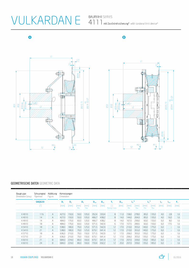
VULKARDAN E 4111 mit Durchdrehsicherung* with torsional limit device*
BAUREIHE SERIES
01/2016
L7
L11
L1
F1x45 ~
L2
Ø D3
min.
Ø D3
max
.
Ø D2
Ø D1
S2M2
S1M1
Ø D1
6
Ø D1
5 T
1
Ø D1
4 +0 -0
.127
KKE401JD00
F1x45~
L2Ø D3
min.
Ø D3
max
.
Ø D2
Ø D1
Ø D1
6
Ø D1
5 T
1
Ø D1
4 +0 -0
.127
S2M2
S1M1
L7
L1
KKE601JG00
A B
GEOMETRISCHE DATEN GEOMETRIC DATA
Baugruppe Schwungrad Abbildung Abmessungen Massenträgheitsmomente Masse Schwerpunktsabstand AnmerkungenDimension Group Flywheel Figure Dimension Mass moments of inertia Mass Distance to center of gravity Notes
SAEJ620 D1 D2 D3 D14 D15 T1 D16 L11) L2
1) L7 L11 F1 J1 J2 M1 M2 S1 S2 Alle Massen, Schwerpunkte und Massenträgheitsmomente beziehen sich auf min. Nabendurchmesser bei max. Nabenlänge1) L1 und L2 beschreiben Standardsituationen und können im Anwendungsfall angepasst werden. Die Auslegung der Naben-
länge erfolgt in Abhängigkeit des Anlagen momentes TN und muss anwendungsbezogen berechnet werden. Besuchen Sie hierfür das VULKAN Engeneering Portal auf unserer Homepage www.vulkan.com oder kontaktieren Sie die VULKAN Vertretung in ihrer Nähe.
All masses, focal points and mass moments of inertia refer to min. hub diameter at max. hub length.1) L1 and L2 describe standard situations and can be adapted to the application. The design of the hub length is carried out
depending on the system torque TN and must be calculated use-oriented. Therefor visit the VULKAN Engineering Portal on our homepage www.vulkan.com or contact the next VULKAN representation.
[“] [mm] [mm] [mm] [mm] [mm] [mm] [-] [mm] [mm] [mm] [mm] [mm] [mm] [mm] [mm] [kgm²] [kgm²] [kg] [kg] [mm] [mm]Min. Max. Teilung / holes Min. Max. Min. Max.
K 4010 11½ A 427,0 150,0 50,0 105,0 352,4 333,4 8 11,0 158,0 278,0 85,0 135,0 4,0 2,8 1,6 0,07 0,63 4,4 46,5 8,3 146,0
K 4010 14 A 427,0 150,0 50,0 105,0 466,7 438,2 8 14,0 144,0 264,0 85,0 135,0 4,0 16,0 1,6 0,18 0,63 6,7 46,6 -3,7 145,9
K 4910 14 A 484,0 170,0 60,0 120,0 466,7 438,2 8 14,0 167,0 299,0 60,0 150,0 6,0 8,0 1,6 0,28 1,57 8,3 83,3 6,3 172,3
K 4910 18 A 484,0 170,0 60,0 120,0 571,5 542,9 6 17,0 157,5 289,5 60,0 150,0 6,0 17,5 1,6 0,56 1,59 12,6 83,6 0,8 172,0
K 5410 18 A 538,0 180,0 70,0 125,0 571,5 542,9 12 17,0 210,0 355,0 140,0 175,0 6,0 – 1,6 0,71 2,79 16,8 111,7 20,9 179,5
K 5410 21 A 538,0 180,0 70,0 125,0 673,1 641,4 12 17,0 210,0 355,0 140,0 175,0 6,0 – 1,6 1,15 2,78 21,4 111,6 17,1 179,4
K 5710 18 A 636,0 210,0 70,0 150,0 571,5 542,9 12 17,0 206,0 355,0 135,0 175,0 6,0 – 1,6 0,83 4,51 18,9 142,3 22,3 175,0
K 5710 21 A 636,0 210,0 70,0 150,0 673,1 641,4 12 17,0 206,0 355,0 135,0 175,0 6,0 – 1,6 1,28 4,52 23,4 142,3 18,5 175,0
K 6010 21 B 684,0 224,0 80,0 160,0 673,1 641,4 12 17,0 207,0 339,0 135,0 185,0 6,0 – 1,6 1,59 5,56 28,4 139,6 28,7 159,9
K 6010 24 B 684,0 224,0 80,0 160,0 733,4 692,2 12 20,0 207,0 339,0 135,0 185,0 6,0 – 1,6 1,97 5,31 31,6 136,5 22,8 159,2

19VULKAN COUPLINGSVULKARDAN E01/2016
GEOMETRISCHE DATEN GEOMETRIC DATA
Baugruppe Schwungrad Abbildung Abmessungen Massenträgheitsmomente Masse Schwerpunktsabstand AnmerkungenDimension Group Flywheel Figure Dimension Mass moments of inertia Mass Distance to center of gravity Notes
SAEJ620 D1 D2 D3 D14 D15 T1 D16 L11) L2
1) L7 L11 F1 J1 J2 M1 M2 S1 S2 Alle Massen, Schwerpunkte und Massenträgheitsmomente beziehen sich auf min. Nabendurchmesser bei max. Nabenlänge1) L1 und L2 beschreiben Standardsituationen und können im Anwendungsfall angepasst werden. Die Auslegung der Naben-
länge erfolgt in Abhängigkeit des Anlagen momentes TN und muss anwendungsbezogen berechnet werden. Besuchen Sie hierfür das VULKAN Engeneering Portal auf unserer Homepage www.vulkan.com oder kontaktieren Sie die VULKAN Vertretung in ihrer Nähe.
All masses, focal points and mass moments of inertia refer to min. hub diameter at max. hub length.1) L1 and L2 describe standard situations and can be adapted to the application. The design of the hub length is carried out
depending on the system torque TN and must be calculated use-oriented. Therefor visit the VULKAN Engineering Portal on our homepage www.vulkan.com or contact the next VULKAN representation.
[“] [mm] [mm] [mm] [mm] [mm] [mm] [-] [mm] [mm] [mm] [mm] [mm] [mm] [mm] [mm] [kgm²] [kgm²] [kg] [kg] [mm] [mm]Min. Max. Teilung / holes Min. Max. Min. Max.
K 4010 11½ A 427,0 150,0 50,0 105,0 352,4 333,4 8 11,0 158,0 278,0 85,0 135,0 4,0 2,8 1,6 0,07 0,63 4,4 46,5 8,3 146,0
K 4010 14 A 427,0 150,0 50,0 105,0 466,7 438,2 8 14,0 144,0 264,0 85,0 135,0 4,0 16,0 1,6 0,18 0,63 6,7 46,6 -3,7 145,9
K 4910 14 A 484,0 170,0 60,0 120,0 466,7 438,2 8 14,0 167,0 299,0 60,0 150,0 6,0 8,0 1,6 0,28 1,57 8,3 83,3 6,3 172,3
K 4910 18 A 484,0 170,0 60,0 120,0 571,5 542,9 6 17,0 157,5 289,5 60,0 150,0 6,0 17,5 1,6 0,56 1,59 12,6 83,6 0,8 172,0
K 5410 18 A 538,0 180,0 70,0 125,0 571,5 542,9 12 17,0 210,0 355,0 140,0 175,0 6,0 – 1,6 0,71 2,79 16,8 111,7 20,9 179,5
K 5410 21 A 538,0 180,0 70,0 125,0 673,1 641,4 12 17,0 210,0 355,0 140,0 175,0 6,0 – 1,6 1,15 2,78 21,4 111,6 17,1 179,4
K 5710 18 A 636,0 210,0 70,0 150,0 571,5 542,9 12 17,0 206,0 355,0 135,0 175,0 6,0 – 1,6 0,83 4,51 18,9 142,3 22,3 175,0
K 5710 21 A 636,0 210,0 70,0 150,0 673,1 641,4 12 17,0 206,0 355,0 135,0 175,0 6,0 – 1,6 1,28 4,52 23,4 142,3 18,5 175,0
K 6010 21 B 684,0 224,0 80,0 160,0 673,1 641,4 12 17,0 207,0 339,0 135,0 185,0 6,0 – 1,6 1,59 5,56 28,4 139,6 28,7 159,9
K 6010 24 B 684,0 224,0 80,0 160,0 733,4 692,2 12 20,0 207,0 339,0 135,0 185,0 6,0 – 1,6 1,97 5,31 31,6 136,5 22,8 159,2
20 VULKAN COUPLINGS VULKARDAN E
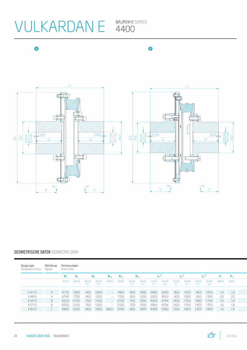
VULKARDAN E 4400BAUREIHE SERIES
01/2016
L1
Ø D2
L2 L9Ø D1
F1x45 ~ F2x45 ~
Ø D3
min.
Ø D3
max
.
Ø D1
2 mi
n.
Ø D1
2 ma
x.
Ø D1
1
S2M2
S1M1
L2 L9
F1x45~
Ø D3
min.
Ø D3
max
.
Ø D2
Ø D1
F2x45~
Ø D1
2 mi
n.Ø
D12
max.
Ø D1
1
S2M2
S1M1
L1
KKE541K000
A B
GEOMETRISCHE DATEN GEOMETRIC DATA
Baugruppe Abbildung Abmessungen Massenträgheitsmomente Masse Schwerpunktsabstand AnmerkungenDimension Group Figure Dimension Mass moments of inertia Mass Distance to center of gravity Notes
D1 D2 D3 D10 D11 D12 L11) L2
1) L91) F1 F2 J1 J2 M1 M2 S1 S2 Alle Massen, Schwerpunkte und Massenträgheitsmomente beziehen sich auf min. Nabendurchmesser bei max. Nabenlänge
1) L1, L2 und L9 beschreiben Standardsituationen und können im Anwendungsfall angepasst werden. Die Auslegung der Naben länge erfolgt in Abhängigkeit des Anlagenmomentes TN und muss anwendungsbezogen berechnet werden. Besuchen Sie hierfür das VULKAN Engeneering Portal auf unserer Homepage www.vulkan.com oder kontaktieren Sie die VULKAN Vertretung in ihrer Nähe.
All masses, focal points and mass moments of inertia refer to min. hub diameter at max. hub length.1) L1, L2 and L9 describe standard situations and can be adapted to the application. The design of the hub length is carried
out depending on the system torque TN and must be calculated use-oriented. Therefor visit the VULKAN Engineering Portal on our homepage www.vulkan.com or contact the next VULKAN representation.
[mm] [mm] [mm] [mm] [mm] [mm] [mm] [mm] [mm] [mm] [mm] [mm] [mm] [mm] [mm] [mm] [kgm²] [kgm²] [kg] [kg] [mm] [mm]Min. Max. Min. Max. Min. Max. Min. Max. Min. Max.
K 4110 A 417,0 140,0 40,0 100,0 – 140,0 40,0 100,0 244,0 324,0 85,0 125,0 85,0 125,0 1,6 1,6 0,22 0,40 26,2 27,3 92,5 97,3
K 4810 A 474,0 170,0 60,0 120,0 – 170,0 60,0 120,0 205,0 355,0 60,0 135,0 60,0 135,0 2,0 2,0 0,41 0,89 38,6 45,2 98,7 107,8
K 5410 B 625,0 210,0 70,0 150,0 – 210,0 70,0 150,0 400,4 470,4 140,0 175,0 140,0 175,0 1,6 1,6 1,13 3,66 75,0 116,8 124,7 142,8
K 5710 B 625,0 210,0 70,0 150,0 – 210,0 70,0 150,0 390,4 470,4 135,0 175,0 135,0 175,0 1,6 1,6 1,43 3,79 80,1 118,8 128,0 144,4
K 6010 C 684,0 224,0 80,0 160,0 682,0 224,0 80,0 160,0 439,0 539,0 135,0 185,0 135,0 185,0 1,6 1,6 5,14 5,45 131,0 134,7 157,0 156,7

21VULKAN COUPLINGSVULKARDAN E01/2016
F1x45~
L2
Ø D3
min.
Ø D3
max
.
Ø D2
Ø D1
L9
F2x45~
Ø D1
2 mi
n.
Ø D1
2 ma
x.
Ø D1
1
Ø D1
0
S2M2
S1M1
L1
KKE601K000
C
GEOMETRISCHE DATEN GEOMETRIC DATA
Baugruppe Abbildung Abmessungen Massenträgheitsmomente Masse Schwerpunktsabstand AnmerkungenDimension Group Figure Dimension Mass moments of inertia Mass Distance to center of gravity Notes
D1 D2 D3 D10 D11 D12 L11) L2
1) L91) F1 F2 J1 J2 M1 M2 S1 S2 Alle Massen, Schwerpunkte und Massenträgheitsmomente beziehen sich auf min. Nabendurchmesser bei max. Nabenlänge
1) L1, L2 und L9 beschreiben Standardsituationen und können im Anwendungsfall angepasst werden. Die Auslegung der Naben länge erfolgt in Abhängigkeit des Anlagenmomentes TN und muss anwendungsbezogen berechnet werden. Besuchen Sie hierfür das VULKAN Engeneering Portal auf unserer Homepage www.vulkan.com oder kontaktieren Sie die VULKAN Vertretung in ihrer Nähe.
All masses, focal points and mass moments of inertia refer to min. hub diameter at max. hub length.1) L1, L2 and L9 describe standard situations and can be adapted to the application. The design of the hub length is carried
out depending on the system torque TN and must be calculated use-oriented. Therefor visit the VULKAN Engineering Portal on our homepage www.vulkan.com or contact the next VULKAN representation.
[mm] [mm] [mm] [mm] [mm] [mm] [mm] [mm] [mm] [mm] [mm] [mm] [mm] [mm] [mm] [mm] [kgm²] [kgm²] [kg] [kg] [mm] [mm]Min. Max. Min. Max. Min. Max. Min. Max. Min. Max.
K 4110 A 417,0 140,0 40,0 100,0 – 140,0 40,0 100,0 244,0 324,0 85,0 125,0 85,0 125,0 1,6 1,6 0,22 0,40 26,2 27,3 92,5 97,3
K 4810 A 474,0 170,0 60,0 120,0 – 170,0 60,0 120,0 205,0 355,0 60,0 135,0 60,0 135,0 2,0 2,0 0,41 0,89 38,6 45,2 98,7 107,8
K 5410 B 625,0 210,0 70,0 150,0 – 210,0 70,0 150,0 400,4 470,4 140,0 175,0 140,0 175,0 1,6 1,6 1,13 3,66 75,0 116,8 124,7 142,8
K 5710 B 625,0 210,0 70,0 150,0 – 210,0 70,0 150,0 390,4 470,4 135,0 175,0 135,0 175,0 1,6 1,6 1,43 3,79 80,1 118,8 128,0 144,4
K 6010 C 684,0 224,0 80,0 160,0 682,0 224,0 80,0 160,0 439,0 539,0 135,0 185,0 135,0 185,0 1,6 1,6 5,14 5,45 131,0 134,7 157,0 156,7

22 VULKAN COUPLINGS VULKARDAN E
Die sorgfältige Absicherung der Technischen Daten ist durch langjährige VULKAN
Erfahrung in Marineantrieben und aufwendige Hausversuche mit verschiedenen
Lastspektren sicher gestellt.
Ähnlich zu den Methoden der Motor-, Getriebe- und Generatorhersteller, werden
die technischen Produktdaten der Kupplungen unter Berücksichtigung der typischen
Belastungsarten differenziert – im Wesentlichen nach den Drehmomenten und
Profilen der verschiedenen Anwendungen:
Following the methods of engine, gearbox and generator manufacturers,
VULKAN is diversifying the technical product data of the couplings depending
on the typical loads, i.e. rating and profiles of the different applications:
The careful validation of the Technical Data is ensured by VULKAN´s long term
experience in marine propulsion and extensive in-house testing with diverse load
spectra.
01/2016
VULKARDAN E
• Unterbrochener Betrieb mit großen Variationen
in Motordrehzahl und/ oder Leistung
• Mit bis zu 1500 Betriebsstunden pro Jahr
• Durchschnittliche Auslastung 55 – 65 % TKN
• Leichter Schiffsbetrieb, z.B.: in Privat- und Charter-
booten, Sport-/ Freizeitboote/ Schiffe- usw.
• Erzeugung von elektrischer Energie im Bereit-
schaftsbetrieb – mit variabler Last
• Unterbrochener Betrieb mit einigen Variationen
in Motordrehzahl und/ oder Leistung
• Mit bis zu 4000 Betriebsstunden pro Jahr
• Durchschnittliche Auslastung 60 – 80 % TKN
• Mittelschwerer Schiffsbetrieb, z.B.: in Charter-
und kommerziellen Booten, Arbeitsboote, Marine-
und Behördenschiffe usw.
• Erzeugung von elektrischer Energie im Grund-
leistungsbetrieb – mit variabler Last
• Kontinuierlicher Betrieb mit geringen oder keinen
Variationen von Motordrehzahl und Leistung
• Unbegrenzte Betriebsstunden pro Jahr, mit bis zu
100 % des Kupplungsnenndrehmomentes (TKN)
für bis zu 100 % der Betriebszeit, durchschnitt-
liche Auslastung 70 – 100 % TKN
• Schwerer Schiffsbetrieb, z.B.: in Handelsschiffen,
Baggerschiffen, Containerschiffen, Fährschiffen usw.
• Erzeugung von elektrischer Energie im Dauerbetrieb –
mit konstanter Last, sehr geringe Lastschwankungen
• Intermittent operation with large variations
in engine speed and/or power
• With up to 1500 operating hours per year
• Average load factor is 55 – 65 % of TKN
• Marine Light service rated, i.e. private and
charter, sport/ leisure activity vessels
• Power Generation in Standby Duty –
standby with variable load
• Intermittent operation with some variations
in engine speed and/or power
• With up to 4000 operating hours per year
• Average load factor is 60 – 80 % of TKN
• Marine Medium service rated, i.e. charter and
commercial crafts, workboats, naval and
government vessels etc.
• Power Generation in Prime Duty –
with variable load
• Continuous operation with little or no
variations in engine speed and power
• Unlimited operating hours per year; with up to
100 % of rated torque (TKN) up to 100 % operating
time, average load factor is 70 – 100 % of TKN
• Marine heavy service rated, i.e. commercial
vessel, dredger, container vessel, ferry, etc.
• Power Generation in Continuous Duty – with
constant load, very little load variation
L LEICHTER BETRIEBLIGHT SERVICE
C KONTINUIERLICHER BETRIEBCONTINUOUS SERVICE
M MITTELSCHWERER BETRIEBMEDIUM SERVICE
KUPPLUNGSAUSWAHL MIT HILFE VON ANWENDUNGSPROFILEN COUPLING SELECTION BY MEANS OF APPLICATION-PROFILES

23VULKAN COUPLINGSVULKARDAN E
AUSLEGUNGSBEISPIEL SAMPLE SELECTION
01/2016
TN [kNm]
Nenndrehmoment Anlage PN [kW]
Nennleistung nN [min-1]
Nenndrehzahl TKN [kNm]
Nenndrehmoment KupplungSt
TemperaturfaktorSL
Faktor AnwendungsprofilRated torque drive line Nominal output Nominal speed Rated torque coupling Temperature factor Factor application profil
L LEICHTER BETRIEBLIGHT SERVICE
AUSWAHL EINER HOCHELASTISCHEN VULKARDAN E KUPPLUNG FÜR EINEN YACHTANTRIEB (LASTPROFIL „LEICHTER BETRIEB“)
SELECTION OF A HIGHLY FLEXIBLE VULKARDAN E COUPLINGFOR A YACHT DRIVELINE (LOADPROFILE „LIGHT SERVICE“)
(TKN-L) = 6,50 kNm ≥ (TN) = 6,00 kNm zeigt, dass die Kupplung VULKARDAN E
K4911..S für die beschriebene Beispielanwendung in Bezug auf die Nenndreh-
momentkapazität geeignet ist.
Die Eignung der hier vorausgewählten Kupplung ist durch eine zusätzliche
Drehschwingungsrechnung zu überprüfen.
Auslegungsbeispiel:
Ein Yachtantrieb mit Hochleistungsmotor und Getrie-
be, einer Leistung von 1540 kW und 2450 1/min,
bei 20 % der Betriebszeit im Vollastbereich, rasch
wechselnder Schiffsgeschwindigkeit mit Betriebszei-
ten zwischen 250 bis 1000 Stunden pro Jahr.
Aus dieser Ausgangsbasis 1540 kW (PN) und 2450
1/min (nN) und freier Propellerkurve ergibt sich ein
Anlagennennmoment von 6,00 kNm (TN) (alternativ
ist das maximale Moment der Motorkurve zu berück-
sichtigen).
Für den Einbau der Kupplung in einen freien
Schwungradanbau resultiert bei der Silikonvariante
ein Temperaturfaktor 1,0 (St) (siehe Erläuterungen
der Technischen Daten – gültig für Si-Elemente).
Auf das Nenndrehmoment der vorausgewählten
Kupplung VULKARDAN E K4911..S (Silikonvariante)
mit 6,50 kNm (TKN) wird zusätzlich der Faktor 1,0
(SL) für das Anwendungsprofil „Leichter Betrieb“
angewandt.
The sample selection is starting from:
A yacht-driveline with high performance engine
and gear transmission, power/speed of 1540 kW
and 2450 1/min, with 20 % of operating time with
full throttle, frequent change in ship´s speed, with
operating times from 250 to 1000 hours per year.
From this starting information 1540 kW (PN) und
2450 1/min (nN) and free propeller-curve a rated
torque of the driveline 6,00 kNm (TN) is resulting
(alternatively the maximum torque of the engine cha-
racteristic has to be considered).
For installation of the coupling into an open fly-
wheel installation a temperature-factor 1,0 (St)
has to be used for the Silicone- elements (see Ex-
planation of Technical Data – valid for Si-elements).
The rated torque of the preselected VULKARDAN E
K4911..S coupling (silicone) of 6,50 kNm (TKN)
has to be additionally corrected with the factor
1,0 (SL) for the application-profile „Light Service“.
(TKN-L) = 6,50 kNm ≥ (TN) = 6,00 kNm shows, that the coupling VULKARDAN E
K4911..S is rated-torque-based suitable for the described sample selection.
The suitability of this preselected coupling is subject to an additional
Torsional Vibration Calculation.
TN= nN
9,55 x PN
TN= 6,00 [kNm]
Nenndrehmoment Anlage
Rated torque drive line
TKN-L = TKN x St x SL
TKN-L = 6,50 [kNm]
Nenndrehmoment Kupplung
Rated torque coupling

24 VULKAN COUPLINGS VULKARDAN E
VULKARDAN EAUSLEGUNGSBEISPIEL SAMPLE SELECTION
01/2016
TN [kNm]
Nenndrehmoment Anlage PN [kW]
Nennleistung nN [min-1]
Nenndrehzahl TKN [kNm]
Nenndrehmoment KupplungSt
TemperaturfaktorSL
Faktor AnwendungsprofilRated torque drive line Nominal output Nominal speed Rated torque coupling Temperature factor Factor application profil
AUSWAHL EINER ELASTISCHEN VULKARDAN G KUPPLUNG FÜR EINEN GENERATOR ANTRIEB (LASTPROFIL „MITTELSCHWERER BETRIEB“)
SELECTION OF A FLEXIBLE VULKARDAN G COUPLING FOR A GENERATOR DRIVELINE (LOADPROFILE „MEDIUM SERVICE“)
Auslegungsbeispiel:
Eine Energiezentrale mit Antrieben aus Motor und
Generator im Grundleistungsbereich, einer Leistung
von 1678 kW und 1800 1/min, mit einer variablen
Leistungs abnahme von durchschnittlich 80 % dekla-
rierter Leistung, mit Betriebs zeiten max. 4000 Stun-
den pro Jahr. Der Motor ist gegenüber dem Generator
flexibel gelagert.
Aus dieser Ausgangsbasis 1678 kW (PN) und
1800 1/min (nN) ergibt sich ein Anlagen nenn-
moment von 8,90 kNm (TN).
Aufgrund der freistehenden Aufstellung und keiner
besonderen Angaben zur Umgebungstemperatur
kann ein Temperaturfaktor von 1,0 (St) angenommen
werden (siehe Erläuterung der Technischen Daten). Auf
das Nenndrehmoment der vorausgewählten Kupplung
VULKARDAN E K4911..S mit 10,40 kNm (TKN)
wird zusätzlich der Faktor 0,89 (SM) für das Anwen-
dungsprofil „Mittelschwerer Betrieb“ angewandt.
(TKN-M) = 9,26 kNm ≥ (TN) = 8,90 kNm zeigt, dass die Kupplung VULKARDAN E
K4911..S für die beschriebene Beispielanwendung in Bezug auf die Nenndreh-
momentkapazität geeignet ist.
Die Eignung der hier vorausgewählten Kupplung ist durch eine zusätzliche
Drehschwingungsrechnung zu überprüfen.
The sample selection is starting from:
A power generation station with drivelines with engine
and generator operating in prime duty, power/speed
of 1678 kW and 1800 1/min, with variable output of
80 % rated power in average, with operating times of
max. 4000 hours per year. The engine is, in relation
to the generator, mounted flexibly.
From this starting information 1678 kW (PN) and
1800 1/min (nN) a rated torque of the driveline
8,9 kNm (TN) is resulting.
Due to the freestanding installation and no further
remarks on the ambient temperature, a tempera-
ture-factor of 1,0 (St) can be estimated (see Expla-
nation of Technical Data). The rated torque of the
preselected VULKARDAN E K4911..S coupling of
10,40 kNm (TKN) has to be additionally corrected
with the factor 0,89 (SM) for the application-profile
„Medium Service“.
(TKN-M) = 9,26 kNm ≥ (TN) = 8,90 kNm shows, that the coupling VULKARDAN E
K4911..S is rated-torque-based suitable for the described sample selection.
The suitability of this preselected coupling is subject to an additional
Torsional Vibration Calculation.
TN= nN
9,55 x PN
TN= 8,90 [kNm]
Nenndrehmoment Anlage
Rated torque drive line
TKN-M = TKN x St x SM
TKN-M = 9,26 [kNm]
Nenndrehmoment Kupplung
Rated torque coupling
M MITTELSCHWERER BETRIEBMEDIUM SERVICE

25VULKAN COUPLINGSVULKARDAN E
AUSLEGUNGSBEISPIEL SAMPLE SELECTION
C KONTINUIERLICHER BETRIEBCONTINUOUS SERVICE
01/2016
TN [kNm]
Nenndrehmoment Anlage PN [kW]
Nennleistung nN [min-1]
Nenndrehzahl TKN [kNm]
Nenndrehmoment KupplungSt
TemperaturfaktorSL
Faktor AnwendungsprofilRated torque drive line Nominal output Nominal speed Rated torque coupling Temperature factor Factor application profil
TN= nN
9,55 x PN
TN= 7,13 [kNm]
Nenndrehmoment Anlage
Rated torque drive line
TKN-C = TKN x St x SC
TKN-C = 8,01 [kNm]
Nenndrehmoment Kupplung
Rated torque coupling
AUSWAHL EINER HOCHELASTISCHEN VULKARDAN E KUPPLUNG FÜR EIN SCHUBSCHIFFANTRIEB (LASTPROFIL „KONTINUIERLICHER BETRIEB“)
SELECTION OF A HIGHLY FLEXIBLE VULKARDAN E COUPLING FOR A PUSHER - DRIVELINE (LOADPROFILE „CONTINUOUS SERVICE“)
(TKN-C) = 8,01 kNm ≥ (TN) = 7,13 kNm zeigt, dass die Kupplung VULKARDAN E
K5412..A für die beschriebene Beispielanwendung in Bezug auf die Nenndreh-
momentkapazität geeignet ist.
Die Eignung der hier vorausgewählten Kupplung ist durch eine zusätzliche
Drehschwingungsrechnung zu überprüfen.
Auslegungsbeispiel:
Ein flussgehendes Schubschiff mit Antrieben aus
Dauerleistungsmotor und Getriebe, einer Leistung
von 1194 kW und 1600 1/min, bei 60 % der Be-
triebszeit im Vollastbereich, langsam wechselnder
Schiffsgeschwindigkeit mit Betriebszeiten bis zu
6000 Stunden pro Jahr.
Aus dieser Ausgangsbasis 1194 kW (PN) und 1600
1/min (nN) und freier Propellerkurve ergibt sich ein
Anlagennennmoment von 7,13 kNm (TN) (alternativ
ist das maximale Moment der Motorkurve zu berück-
sichtigen).
Aufgrund der freistehenden Aufstellung und keiner be-
sonderen Angaben zur Umgebungstemperatur kann
ein Temperaturfaktor von 1,0 (St) angenommen wer-
den (siehe Erläuterung der Technischen Daten). Auf
das Nenndrehmoment der vorausgewählten Kupplung
VULKARDAN E K5412..A mit 10,40 kNm (TKN)
wird zusätzlich der Faktor 0,77 (SC) für das Anwen-
dungsprofil „Kontinuierlicher Betrieb“ angewandt.
The sample selection is starting from:
A river-going pusher with drivelines of continuous
rated engine and gear transmission, power/speed
of 1194 kW and 1600 1/min, with 60 % of operating
time with full throttle, slow change in ship´s speed,
with operating times up to 6000 hours per year.
From this starting information 1194 kW (PN) und
1600 1/min (nN) and free propeller-curve a rated
torque of the driveline 7,13 kNm (TN) is resulting
(alternatively the maximum torque of the engine cha-
racteristic has to be considered).
Due to the freestanding installation and no further
remarks on the ambient temperature, a tempe-
rature-factor of 1,0 (St) can be estimated (see
Explanation of Technical Data). The rated torque
of the preselected VULKARDAN E K5412..A (NR-
element) coupling of 10,40 kNm (TKN) has to be
additionally corrected with the factor 0,77 (SC) for
the application-profile „Continuous Service“.
(TKN-C) = 8,01 kNm ≥ (TN) = 7,13 kNm shows, that the coupling VULKARDAN E
K5412..A is rated-torque-based suitable for the described sample selection.
The suitability of this preselected coupling is subject to an additional
Torsional Vibration Calculation.
26 VULKAN COUPLINGS VULKARDAN E 01/2016
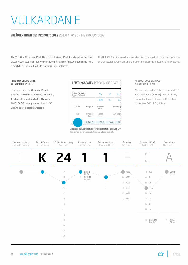
Alle VULKAN Couplings Produkte sind mit einem Produktcode gekennzeichnet.
Dieser Code setzt sich aus verschiedenen Parameter-Angaben zusammen und
ermöglicht es, unsere Produkte eindeutig zu identifizieren.
All VULKAN Couplings products are identified by a product code. This code con-
sists of several parameters and it enables the clear identification of all products.
VULKARDAN EERLÄUTERUNGEN DES PRODUKTCODES EXPLANATIONS OF THE PRODUCT CODE
PRODUKTCODE BEISPIELVULKARDAN E (K 2411)
Hier haben wir den Code am Beispiel
einer VULKARDAN E (K 2411), Größe 24,
1-reihig, Elementsteifigkeit 1, Baureihe
4000, SAE-Schwungradanschluss 11.5",
Gummi entschlüsselt dargestellt.
PRODUCT CODE EXAMPLEVULKARDAN E (K 2411)
We have decoded here the product code of
a VULKARDAN E (K 2411), Size 24, 1 row,
Element stiffness 1, Series 4000, Flywheel
connection SAE 11.5", Rubber.
LEISTUNGSDATEN PERFORMANCE DATA
Kupplungstyp Type of Coupling TKN L3) M 3) C 3) TKmax1 TKmax2 ΔTmax TKW PKV50;1h nKmax ΔKr
2) Crdyn1) CTdyn
1) 2) ψ1) 2)
[kNm] SL SM SC [kNm] [kNm] [kNm] [kNm] [kW] [1/min] [mm] [kN/mm] [kNm/rad]nominal
nominal
Größe Baugruppe Nenndreh-moment
Anwendungs faktor Dreh-moment1
Dreh-moment2
Drehmoment Bereich
Wechsel-drehmoment
Verlust-leistung
Drehzahl Radialer Kupplungsversatz
Radiale Federsteife
DynamischeDrehfedersteife
Verhältnismäßige Dämpfung
Size Dimension Group
Nominal Torque
Duty-Class Factor Torque1 Torque2 Torque Range
Vibratory Torque
Power Loss
Rotational Speed
Radial Coupling Displacement
Radial Stiffness
Dynamic Torsio-nal Stiffness
Relative Damping
K 2411 K 2410 0,82 1,00 0,89 0,77 0,95 2,27 0,94 0,25 0,248 6000 2,0 0,75 3,50 1,00K 2415 K 2410 1,04 1,00 0,89 0,77 1,20 2,88 1,25 0,25 0,248 6000 1,2 1,29 6,00 1,13K 2412 K 2410 1,04 1,00 0,89 0,77 1,20 2,88 1,55 0,25 0,248 6000 0,8 1,79 8,30 1,13K 2814 K 2810 1,30 1,00 0,89 0,77 1,50 3,60 0,98 0,40 0,287 5100 2,4 0,64 4,10 0,75K 2811 K 2810 1,30 1,00 0,89 0,77 1,50 3,60 1,49 0,40 0,287 5100 2,4 0,86 5,50 1,00K 2815 K 2810 1,63 1,00 0,89 0,77 1,88 4,50 1,97 0,40 0,287 5100 1,4 1,47 9,40 1,13K 2812 K 2810 1,63 1,00 0,89 0,77 1,88 4,50 2,45 0,40 0,287 5100 1,0 2,04 13,00 1,13K 3214 K 3210 1,63 1,00 0,89 0,77 1,88 4,50 1,14 0,50 0,259 4900 3,2 0,57 4,20 0,75K 3211 K 3210 1,63 1,00 0,89 0,77 1,88 4,50 1,74 0,50 0,259 4900 3,2 0,74 5,50 1,00K 3215 K 3210 1,95 1,00 0,89 0,77 2,25 5,40 2,30 0,50 0,259 4900 1,6 1,52 11,30 1,13K 3212 K 3210 1,95 1,00 0,89 0,77 2,25 5,40 2,86 0,50 0,259 4900 1,1 2,1 15,60 1,13K 3414 K 3410 2,08 1,00 0,89 0,77 2,40 5,76 1,58 0,64 0,333 4250 4,4 0,51 5,40 0,75K 3411 K 3410 2,08 1,00 0,89 0,77 2,40 5,76 2,41 0,64 0,333 4250 4,4 0,70 7,50 1,00K 3415 K 3410 2,60 1,00 0,89 0,77 3,00 7,20 3,19 0,64 0,333 4250 2,2 1,34 14,70 1,13K 3412 K 3410 2,60 1,00 0,89 0,77 3,00 7,20 3,96 0,64 0,333 4250 1,6 1,85 20,50 1,13K 4014 K 4010 3,25 1,00 0,89 0,77 3,75 9,00 2,45 1,00 0,337 3600 5,9 0,51 8,00 0,75K 4011 K 4010 3,25 1,00 0,89 0,77 3,75 9,00 3,72 1,00 0,337 3600 5,9 0,70 11,00 1,00K 4015 K 4010 4,10 1,00 0,89 0,77 4,73 11,34 4,93 1,00 0,337 3600 3,1 1,34 21,00 1,13K 4012 K 4010 4,10 1,00 0,89 0,77 4,73 11,34 6,12 1,00 0,337 3600 2,3 1,85 29,00 1,13K 4914 K 4910 5,20 1,00 0,89 0,77 6,00 14,40 4,31 1,60 0,440 2750 8,2 0,52 16,50 0,75K 4911 K 4910 5,20 1,00 0,89 0,77 6,00 14,40 6,55 1,60 0,440 2750 8,2 0,69 22,00 1,00K 4915 K 4910 6,50 1,00 0,89 0,77 7,50 18,00 8,68 1,60 0,440 2750 4,8 1,18 37,50 1,13K 4912 K 4910 6,50 1,00 0,89 0,77 7,50 18,00 10,79 1,60 0,440 2750 3,5 1,64 52,00 1,13
Auszug aus den Leistungsdaten. Für vollständige Daten siehe Seite 8 ff.
Excerpt from performance data. Complete data see page 8 ff.
Komplettkupplung Produktfamilie Größenbezeichnung Elementreihen Elementsteifigkeit Baureihe Schwungrad SAE MaterialcodeComplete coupling Product family Size code Element rows Element stiffness Key Series Flywheel SAE Material code
1 K 24 1 1 F C A1 K 17 1 1 REIHE
1 ROW4 F 4000 J 6.5 A Gummi
Rubber23 2 2 REIHEN
2 ROWS1 G 4001 A 8
24 5 I 4110 B 10
28 2 J 4111 C 11.5
32 K 4400 D 14
34 L 4401 F 18
40 G 21
41 H 24
48
49 0 Nicht SAE Non SAE
S Silikon Silicone
54
57
60

27VULKAN COUPLINGSVULKARDAN E
210
220
200
190
180
170
160
150
140
130
120
110
100
9080
7060
5040
3020
100
NOTIZEN NOTICE

28 VULKAN COUPLINGS VULKARDAN E
210
220
200
190
180
170
160
150
140
130
120
110
100
9080
7060
5040
3020
100
VULKARDAN ENOTIZEN NOTICE

29VULKAN COUPLINGSVULKARDAN E
210
220
200
190
180
170
160
150
140
130
120
110
100
9080
7060
5040
3020
100

30 VULKAN COUPLINGS VULKARDAN E
ONLINE-SERVICEWEITERE INFORMATIONEN FINDEN SIE AUF WWW.VULKAN.COM FOR FURTHER INFORMATION, PLEASE REFER TO OUR WEBSITE WWW.VULKAN.COM
AUTORISIERTE HÄNDLER www.vulkan.com/de-de/couplings/kontakt
AUTHORISED DISTRIBUTORS www.vulkan.com/en-us/couplings/contact
VIDEOS www.vulkan.com/de-de/couplings/
downloads-videos/videos
VIDEOS www.vulkan.com/en-us/couplings/ downloads-videos/videos
KATALOGE & BROSCHÜREN www.vulkan.com/de-de/couplings/
downloads-videos
CATALOGUES & BROCHURES www.vulkan.com/en-us/couplings/ downloads-videos
VULKAN ENGINEERING PORTALwww.vulkan.com/de-de/couplings/
service/vulkan-engineering-portal
VULKAN ENGINEERING PORTALwww.vulkan.com/en-us/couplings/ service/vulkan-engineering-portal
PRODUKTSELEKTORwww.vulkan.com/de-de/couplings/
service/produktselektor
PRODUCT SELECTORwww.vulkan.com/en-us/couplings/ service/product-selector
VULKARDAN E www.vulkan.com/de-de/couplings
produkte/hochelastische-kupplungen/vulkardan-e
VULKARDAN E www.vulkan.com/en-us/couplings/ products/highly-flexible-couplings/vulkardan-e

31VULKAN COUPLINGSVULKARDAN E
GÜLTIGKEITSKLAUSEL
Die vorliegende Broschüre ersetzt alle vorherigen Ausgaben, ältere
Drucke verlieren ihre Gültigkeit. VULKAN ist berechtigt, aufgrund neuerer
Entwicklungen die in dieser Broschüre enthaltenen Daten entsprechend
anzupassen und zu verändern. Die neuen Daten gelten nur für nach
der Änderung bestellte Kupplungen. Es liegt im Verantwortungsbereich des
Anwenders dafür zu sorgen, dass ausschließlich die aktuelle Katalog-
version verwendet wird. Der jeweils aktuelle Stand ist auf der Webseite
von VULKAN unter www.vulkan.com jederzeit abrufbar.
Die Angaben in dieser Broschüre beziehen sich auf den technischen
Standard gültig im Hause VULKAN und stehen unter den in den Erläu-
terungen definierten Bedingungen. Es liegt allein im Entscheidungs- und
Verantwortungsrahmen des Systemverantwortlichen für die Antriebslinie,
entsprechende Rückschlüsse auf das Systemverhalten zu ziehen.
VULKAN Drehschwingungsanalysen berücksichtigen in der Regel nur das
rein mechanische Schwingungsersatzsystem. Als reiner Komponentenher-
steller übernimmt VULKAN mit der Analyse des Drehschwingungssystems
(stationär, transient) nicht die Systemverantwortung! Die Genauigkeit
der Analyse hängt von der Genauigkeit der verwendeten bzw. der
VULKAN zur Verfügung gestellten Daten ab.
Änderungen aufgrund des technischen Fortschritts sind vorbehalten.
Bei Unklarheiten bzw. Rückfragen kontaktieren Sie bitte VULKAN.
Stand: 01/2016
Das Recht auf Vervielfältigung, Nachdruck und Übersetzungen behalten
wir uns vor. Maß- und Konstruktionsänderungen vorbehalten.
VALIDITY CLAUSE
The present catalogue shall replace all previous editions, any previous
printings shall no longer be valid. Based on new developments, VULKAN
reserves the right to amend and change any details contained in this
catalogue respectively. The new data shall only apply with respect to
couplings that were ordered after said amendment or change. It shall
be the responsibility of the user to ensure that only the latest catalogue
issue will be used. The respective latest issue can be seen on the website
of VULKAN on www.vulkan.com.
The data contained in this catalogue refer to the technical standard
as presently used by VULKAN with defined conditions according to
the explanations. It shall be the sole responsibility and decision of the
system administrator for the drive line to draw conclusions about the
system behaviour.
VULKAN torsional vibration analysis usually only consider the pure
mechanical mass-elastic system. Being a component manufacturer
exclusively, VULKAN assumes no system responsibility with the analysis
of the torsional vibration system (stationary, transiently)! The accuracy
of the analysis depends on the exactness of the used data and the data
VULKAN is provided with, respectively.
Any changes due to the technological progress are reserved. For ques-
tions or queries please contact VULKAN.
Status: 01/2016
All duplication, reprinting and translation rights are reserved. We reserve
the right to modify dimensions and constructions without prior notice.

Head Office: VULKAN Kupplungs- und Getriebebau Bernhard Hackforth GmbH & Co. KG | Heerstraße 66 | 44653 Herne | GermanyPhone + 49 (0) 2325 922-0 | Fax + 49 (0) 2325 71110 | Mail [email protected]
www.vulkan.com