Embed Size (px)
Citation preview
ENGINE
3.2L V6 4V Engine Mechanical, Fuel Injection Ignition, Engine Codes: BAA, BMX
00 - GENERAL, TECHNICAL DATA
TECHNICAL DATA
Technical data
Engine specifications --> Engine data
Engine number
Fig. 1: Identifying Engine Number Located On Vibration Damper Courtesy of VOLKSWAGEN UNITED STATES, INC.
The engine number "engine code" and "serial number" is located next to vibration damper on cylinder block under the coolant pump.
The engine number consists of up to nine characters (alphanumeric). The first part (maximal 3 characters) makes up the engine code, and the second part (6 characters), the serial number. If more than 999,999 engines with the same engine code are produced, the first of the six characters is replaced with a letter.
In addition, a sticker with "engine code" and "serial number" is affixed to intake manifold.
The engine code is also included on vehicle data plate.
Engine data
Engine code BAA BMXManufactured 03.03 --> 04.04 -->Cylinder arrangement VR * See note VR * See noteCylinder angle 15.0° 15.0°
2006 Volkswagen Touareg
ENGINE 3.2L V6 4V Engine Mechanical, Fuel Injection Ignition, Engine Codes: BAA, BMX
2006 Volkswagen Touareg
ENGINE 3.2L V6 4V Engine Mechanical, Fuel Injection Ignition, Engine Codes: BAA, BMX
Microsoft
Sunday, September 20, 2009 9:14:15 AM Page 1 © 2005 Mitchell Repair Information Company, LLC.
Microsoft
Sunday, September 20, 2009 9:14:24 AM Page 1 © 2005 Mitchell Repair Information Company, LLC.
*VR = V-Arrangment in compact in-line design
*In exceptional circumstances min. 95 RON, however with reduced performance
*Two independently variable camshafts.
10 - ENGINE - ASSEMBLY
ENGINE, REMOVING AND INSTALLING
Engine, removing and installing
Engine, removing --> Engine, removing
Securing engine to engine stand --> Engine, securing to assembly stand
Installing engine --> Engine, installing
Displacement ltr. 3.2 3.2Output kW at RPM 162/6000 177/6000Torque Nm at RPM 300/4000 310/3200Bore dia. mm 84.0 84.0Stroke mm 95.9 95.9Compression ratio 11.25 10.85Valves per cylinder 4 4RON min. 98 unleaded * See note 98 unleaded * See noteSystem designation Motronic ME7.1.1 Motronic ME7.1.1Ignition sequence 1-5-3-6-2-4 1-5-3-6-2-4Knock control 2 knock sensors 2 knock sensorsOxygen sensor regulation 4 sensors 4 sensorsOn Board Diagnostic (OBD) OBD II yesCatalytic converter yes yesExhaust gas recirculation no noCharging no noSecondary air injection (AIR) system yes yesElectronic Power Control (EPC) yes yesVariable intake manifold yes yesVariable valve timing Yes * See note Yes * See noteLeak diagnostic system yes yes
2006 Volkswagen Touareg
ENGINE 3.2L V6 4V Engine Mechanical, Fuel Injection Ignition, Engine Codes: BAA, BMX
Microsoft
Sunday, September 20, 2009 9:14:16 AM Page 2 © 2005 Mitchell Repair Information Company, LLC.
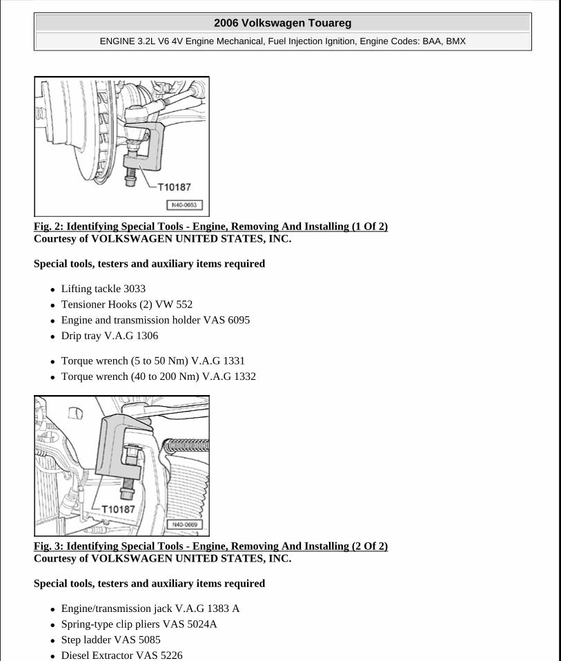
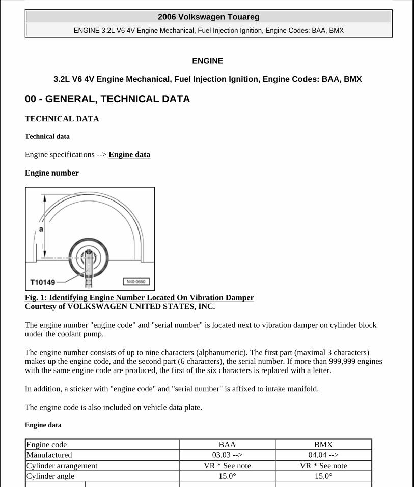
Fig. 2: Identifying Special Tools - Engine, Removing And Installing (1 Of 2) Courtesy of VOLKSWAGEN UNITED STATES, INC.
Special tools, testers and auxiliary items required
Lifting tackle 3033
Tensioner Hooks (2) VW 552
Engine and transmission holder VAS 6095
Drip tray V.A.G 1306
Torque wrench (5 to 50 Nm) V.A.G 1331
Torque wrench (40 to 200 Nm) V.A.G 1332
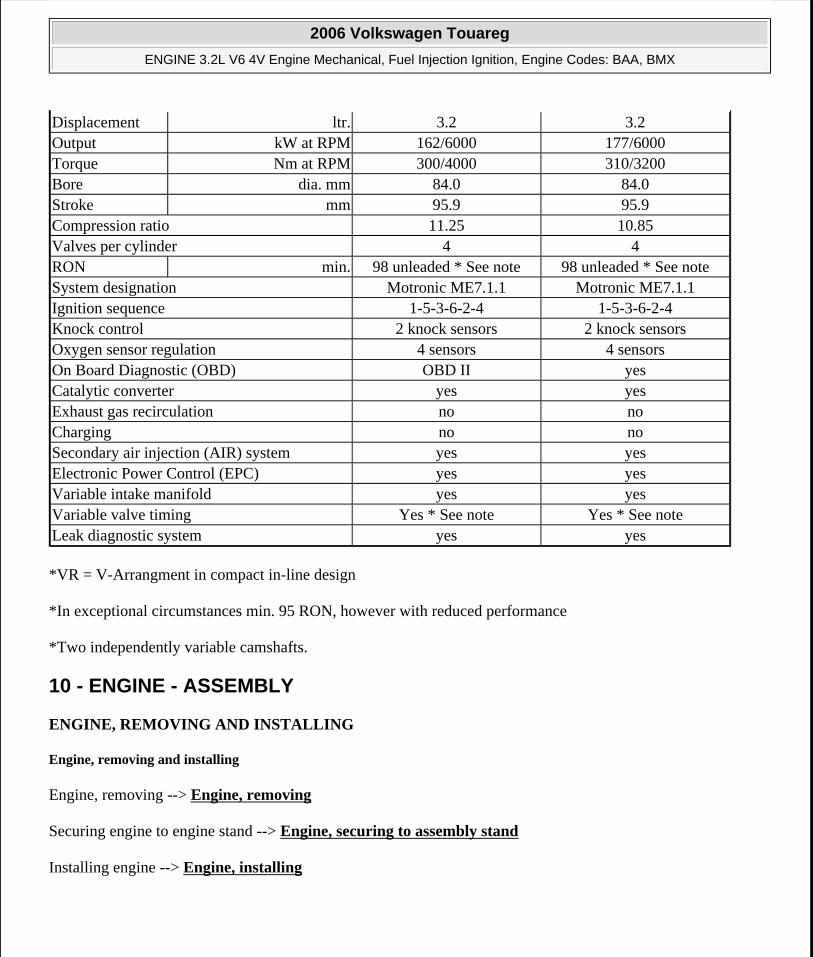
Fig. 3: Identifying Special Tools - Engine, Removing And Installing (2 Of 2) Courtesy of VOLKSWAGEN UNITED STATES, INC.
Special tools, testers and auxiliary items required
Engine/transmission jack V.A.G 1383 A
Spring-type clip pliers VAS 5024A
Step ladder VAS 5085
Diesel Extractor VAS 5226
2006 Volkswagen Touareg
ENGINE 3.2L V6 4V Engine Mechanical, Fuel Injection Ignition, Engine Codes: BAA, BMX
Microsoft
Sunday, September 20, 2009 9:14:16 AM Page 3 © 2005 Mitchell Repair Information Company, LLC.
Shop crane VAS 6100
Scissor lift table VAS 6131
Not illustrated:
Adapter V.A.G 1318/20
Adapter V.A.G 1318/20-1
Container for removed components V.A.G 1698
Left subframe mounting VAS 6131/6-1
Right subframe mounting VAS 6131/6-2
Left suspension support VAS 6131/6-3
Right suspension support VAS 6131/6-4
Supports VAS 6131/6-5 (Qty. 2)
Supports VAS 6131/6-6 (Qty. 2)
Transmission support VAS 6131/6-7
V6 engine support VAS 6131/7
Grease (Vehicles with manual transmission) G 000 1000
Cable tie
Engine, removing
Work procedure
The engine with transmission is removed downward.
CAUTION: Fuel supply lines are under pressure! Wear protective goggles and protective gloves to avoid damage and contact with skin. Before removing from hose connection wrap a cloth around the connection. Then release pressure by carefully pulling hose off connection.
NOTE: To allow free rotation of the drive axle, move the selector lever in the "N" position.
Leave the key in the ignition lock to prevent the steering wheel lock from engaging.
It is advisable to remove the front wheels before removing the engine/transmission assembly. The vehicle can be lowered on the hoist until the cover plates of the brake discs are just above the floor. This enables the most ergonomic work position possible regarding accessibility of components in the engine compartment.
To prevent damage to the removed components, use parts trolley V.A.G 1698 for storage.
2006 Volkswagen Touareg
ENGINE 3.2L V6 4V Engine Mechanical, Fuel Injection Ignition, Engine Codes: BAA, BMX
Microsoft
Sunday, September 20, 2009 9:14:16 AM Page 4 © 2005 Mitchell Repair Information Company, LLC.
When the engine is installed in the engine compartment some components cannot be removed or can only be removed with great difficulty. Therefore determine which components are faulty before removing engine.
Check DTC memories of all control modules, before removing engine:
Disconnecting batteries
The procedure must be strictly followed!
Switch off ignition and all electrical consumers.
Disconnect battery under drivers seat. --> 27 - BATTERY, STARTER, GENERATOR, CRUISE CONTROL
Work procedure
Remove left and right wiper arms: --> 92 - WINDSHIELD WIPER AND WASHER SYSTEM
Remove engine compartment cover seal off bulkhead.
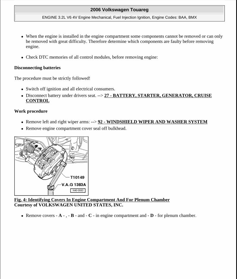
Fig. 4: Identifying Covers In Engine Compartment And For Plenum Chamber Courtesy of VOLKSWAGEN UNITED STATES, INC.
Remove covers - A - , - B - and - C - in engine compartment and - D - for plenum chamber.
2006 Volkswagen Touareg
ENGINE 3.2L V6 4V Engine Mechanical, Fuel Injection Ignition, Engine Codes: BAA, BMX
Microsoft
Sunday, September 20, 2009 9:14:16 AM Page 5 © 2005 Mitchell Repair Information Company, LLC.
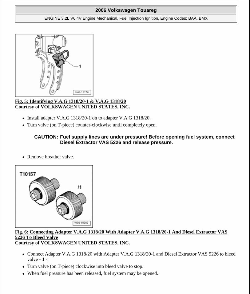
Fig. 5: Identifying V.A.G 1318/20-1 & V.A.G 1318/20 Courtesy of VOLKSWAGEN UNITED STATES, INC.
Install adapter V.A.G 1318/20-1 on to adapter V.A.G 1318/20.
Turn valve (on T-piece) counter-clockwise until completely open.
Remove breather valve.
Fig. 6: Connecting Adapter V.A.G 1318/20 With Adapter V.A.G 1318/20-1 And Diesel Extractor VAS 5226 To Bleed Valve Courtesy of VOLKSWAGEN UNITED STATES, INC.
Connect Adapter V.A.G 1318/20 with Adapter V.A.G 1318/20-1 and Diesel Extractor VAS 5226 to bleed valve - 1 -.
Turn valve (on T-piece) clockwise into bleed valve to stop.
When fuel pressure has been released, fuel system may be opened.
CAUTION: Fuel supply lines are under pressure! Before opening fuel system, connect Diesel Extractor VAS 5226 and release pressure.
2006 Volkswagen Touareg
ENGINE 3.2L V6 4V Engine Mechanical, Fuel Injection Ignition, Engine Codes: BAA, BMX
Microsoft
Sunday, September 20, 2009 9:14:16 AM Page 6 © 2005 Mitchell Repair Information Company, LLC.
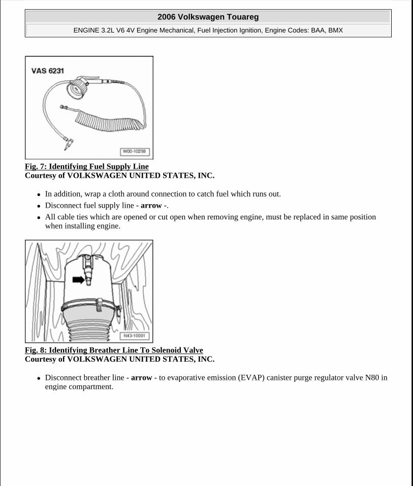
Fig. 7: Identifying Fuel Supply Line Courtesy of VOLKSWAGEN UNITED STATES, INC.
In addition, wrap a cloth around connection to catch fuel which runs out.
Disconnect fuel supply line - arrow -.
All cable ties which are opened or cut open when removing engine, must be replaced in same position when installing engine.
Fig. 8: Identifying Breather Line To Solenoid Valve Courtesy of VOLKSWAGEN UNITED STATES, INC.
Disconnect breather line - arrow - to evaporative emission (EVAP) canister purge regulator valve N80 in engine compartment.
2006 Volkswagen Touareg
ENGINE 3.2L V6 4V Engine Mechanical, Fuel Injection Ignition, Engine Codes: BAA, BMX
Microsoft
Sunday, September 20, 2009 9:14:16 AM Page 7 © 2005 Mitchell Repair Information Company, LLC.
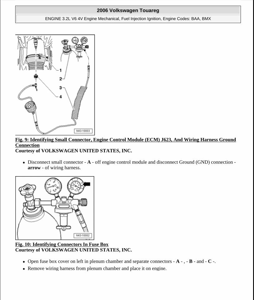
Fig. 9: Identifying Small Connector, Engine Control Module (ECM) J623, And Wiring Harness Ground Connection Courtesy of VOLKSWAGEN UNITED STATES, INC.
Disconnect small connector - A - off engine control module and disconnect Ground (GND) connection - arrow - of wiring harness.
Fig. 10: Identifying Connectors In Fuse Box Courtesy of VOLKSWAGEN UNITED STATES, INC.
Open fuse box cover on left in plenum chamber and separate connectors - A - , - B - and - C -.
Remove wiring harness from plenum chamber and place it on engine.
2006 Volkswagen Touareg
ENGINE 3.2L V6 4V Engine Mechanical, Fuel Injection Ignition, Engine Codes: BAA, BMX
Microsoft
Sunday, September 20, 2009 9:14:16 AM Page 8 © 2005 Mitchell Repair Information Company, LLC.
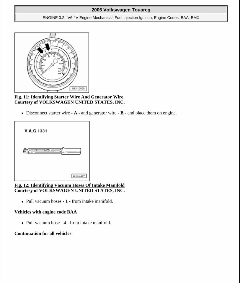
Fig. 11: Identifying Starter Wire And Generator Wire Courtesy of VOLKSWAGEN UNITED STATES, INC.
Disconnect starter wire - A - and generator wire - B - and place them on engine.
Fig. 12: Identifying Vacuum Hoses Of Intake Manifold Courtesy of VOLKSWAGEN UNITED STATES, INC.
Pull vacuum hoses - 1 - from intake manifold.
Vehicles with engine code BAA
Pull vacuum hose - 4 - from intake manifold.
Continuation for all vehicles
2006 Volkswagen Touareg
ENGINE 3.2L V6 4V Engine Mechanical, Fuel Injection Ignition, Engine Codes: BAA, BMX
Microsoft
Sunday, September 20, 2009 9:14:16 AM Page 9 © 2005 Mitchell Repair Information Company, LLC.
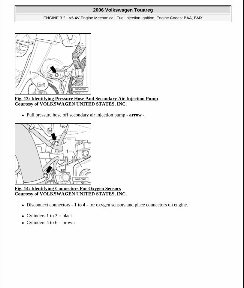
Fig. 13: Identifying Pressure Hose And Secondary Air Injection Pump Courtesy of VOLKSWAGEN UNITED STATES, INC.
Pull pressure hose off secondary air injection pump - arrow -.
Fig. 14: Identifying Connectors For Oxygen Sensors Courtesy of VOLKSWAGEN UNITED STATES, INC.
Disconnect connectors - 1 to 4 - for oxygen sensors and place connectors on engine.
Cylinders 1 to 3 = black
Cylinders 4 to 6 = brown
2006 Volkswagen Touareg
ENGINE 3.2L V6 4V Engine Mechanical, Fuel Injection Ignition, Engine Codes: BAA, BMX
Microsoft
Sunday, September 20, 2009 9:14:16 AM Page 10 © 2005 Mitchell Repair Information Company, LLC.
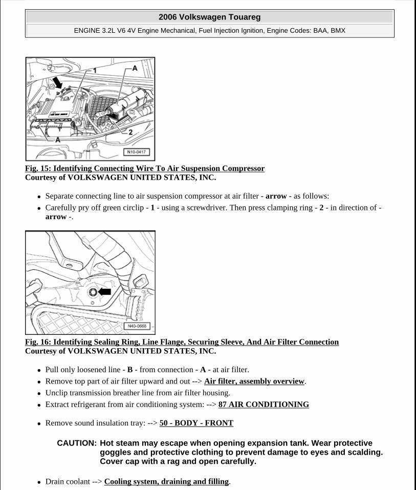
Fig. 15: Identifying Connecting Wire To Air Suspension Compressor Courtesy of VOLKSWAGEN UNITED STATES, INC.
Separate connecting line to air suspension compressor at air filter - arrow - as follows:
Carefully pry off green circlip - 1 - using a screwdriver. Then press clamping ring - 2 - in direction of - arrow -.
Fig. 16: Identifying Sealing Ring, Line Flange, Securing Sleeve, And Air Filter Connection Courtesy of VOLKSWAGEN UNITED STATES, INC.
Pull only loosened line - B - from connection - A - at air filter.
Remove top part of air filter upward and out --> Air filter, assembly overview.
Unclip transmission breather line from air filter housing.
Extract refrigerant from air conditioning system: --> 87 AIR CONDITIONING
Remove sound insulation tray: --> 50 - BODY - FRONT
Drain coolant --> Cooling system, draining and filling.
CAUTION: Hot steam may escape when opening expansion tank. Wear protective goggles and protective clothing to prevent damage to eyes and scalding. Cover cap with a rag and open carefully.
2006 Volkswagen Touareg
ENGINE 3.2L V6 4V Engine Mechanical, Fuel Injection Ignition, Engine Codes: BAA, BMX
Microsoft
Sunday, September 20, 2009 9:14:16 AM Page 11 © 2005 Mitchell Repair Information Company, LLC.
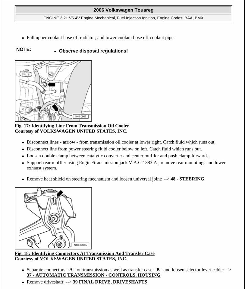
Pull upper coolant hose off radiator, and lower coolant hose off coolant pipe.
Fig. 17: Identifying Line From Transmission Oil Cooler Courtesy of VOLKSWAGEN UNITED STATES, INC.
Disconnect lines - arrow - from transmission oil cooler at lower right. Catch fluid which runs out.
Disconnect line from power steering fluid cooler below on left. Catch fluid which runs out.
Loosen double clamp between catalytic converter and center muffler and push clamp forward.
Support rear muffler using Engine/transmission jack V.A.G 1383 A , remove rear mountings and lower exhaust system.
Remove heat shield on steering mechanism and loosen universal joint: --> 48 - STEERING
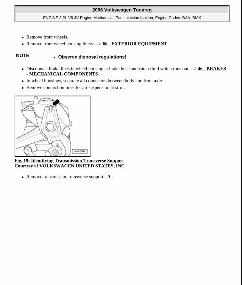
Fig. 18: Identifying Connectors At Transmission And Transfer Case Courtesy of VOLKSWAGEN UNITED STATES, INC.
Separate connectors - A - on transmission as well as transfer case - B - and loosen selector lever cable: --> 37 - AUTOMATIC TRANSMISSION - CONTROLS, HOUSING
Remove driveshaft: --> 39 FINAL DRIVE, DRIVESHAFTS
NOTE: Observe disposal regulations!
2006 Volkswagen Touareg
ENGINE 3.2L V6 4V Engine Mechanical, Fuel Injection Ignition, Engine Codes: BAA, BMX
Microsoft
Sunday, September 20, 2009 9:14:16 AM Page 12 © 2005 Mitchell Repair Information Company, LLC.
Remove front wheels.
Remove front wheel housing liners: --> 66 - EXTERIOR EQUIPMENT
Disconnect brake lines in wheel housing at brake hose and catch fluid which runs out. --> 46 - BRAKES - MECHANICAL COMPONENTS
In wheel housings, separate all connectors between body and front axle.
Remove connection lines for air suspension at strut.
Fig. 19: Identifying Transmission Transverse Support Courtesy of VOLKSWAGEN UNITED STATES, INC.
Remove transmission transverse support - A -.
NOTE: Observe disposal regulations!
2006 Volkswagen Touareg
ENGINE 3.2L V6 4V Engine Mechanical, Fuel Injection Ignition, Engine Codes: BAA, BMX
Microsoft
Sunday, September 20, 2009 9:14:16 AM Page 13 © 2005 Mitchell Repair Information Company, LLC.
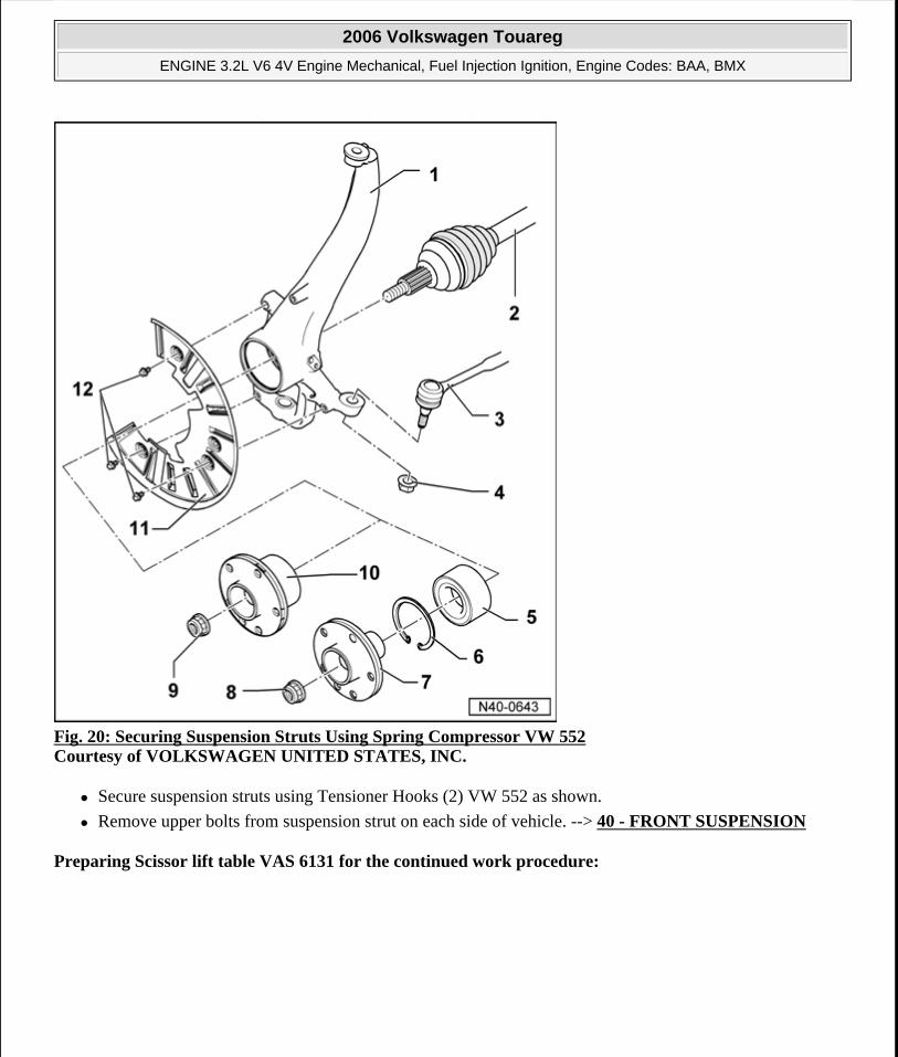
Fig. 20: Securing Suspension Struts Using Spring Compressor VW 552 Courtesy of VOLKSWAGEN UNITED STATES, INC.
Secure suspension struts using Tensioner Hooks (2) VW 552 as shown.
Remove upper bolts from suspension strut on each side of vehicle. --> 40 - FRONT SUSPENSION
Preparing Scissor lift table VAS 6131 for the continued work procedure:
2006 Volkswagen Touareg
ENGINE 3.2L V6 4V Engine Mechanical, Fuel Injection Ignition, Engine Codes: BAA, BMX
Microsoft
Sunday, September 20, 2009 9:14:16 AM Page 14 © 2005 Mitchell Repair Information Company, LLC.
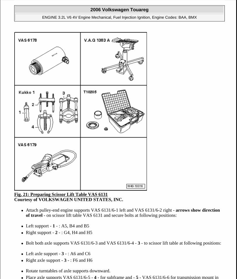
Fig. 21: Preparing Scissor Lift Table VAS 6131 Courtesy of VOLKSWAGEN UNITED STATES, INC.
Attach pulley-end engine supports VAS 6131/6-1 left and VAS 6131/6-2 right - arrows show direction of travel - on scissor lift table VAS 6131 and secure bolts at following positions:
Left support - 1 - : A5, B4 and B5
Right support - 2 - : G4, H4 and H5
Bolt both axle supports VAS 6131/6-3 and VAS 6131/6-4 - 3 - to scissor lift table at following positions:
Left axle support - 3 - : A6 and C6
Right axle support - 3 - : F6 and H6
Rotate turntables of axle supports downward.
Place axle supports VAS 6131/6-5 - 4 - for subframe and - 5 - VAS 6131/6-6 for transmission mount in
2006 Volkswagen Touareg
ENGINE 3.2L V6 4V Engine Mechanical, Fuel Injection Ignition, Engine Codes: BAA, BMX
Microsoft
Sunday, September 20, 2009 9:14:16 AM Page 15 © 2005 Mitchell Repair Information Company, LLC.
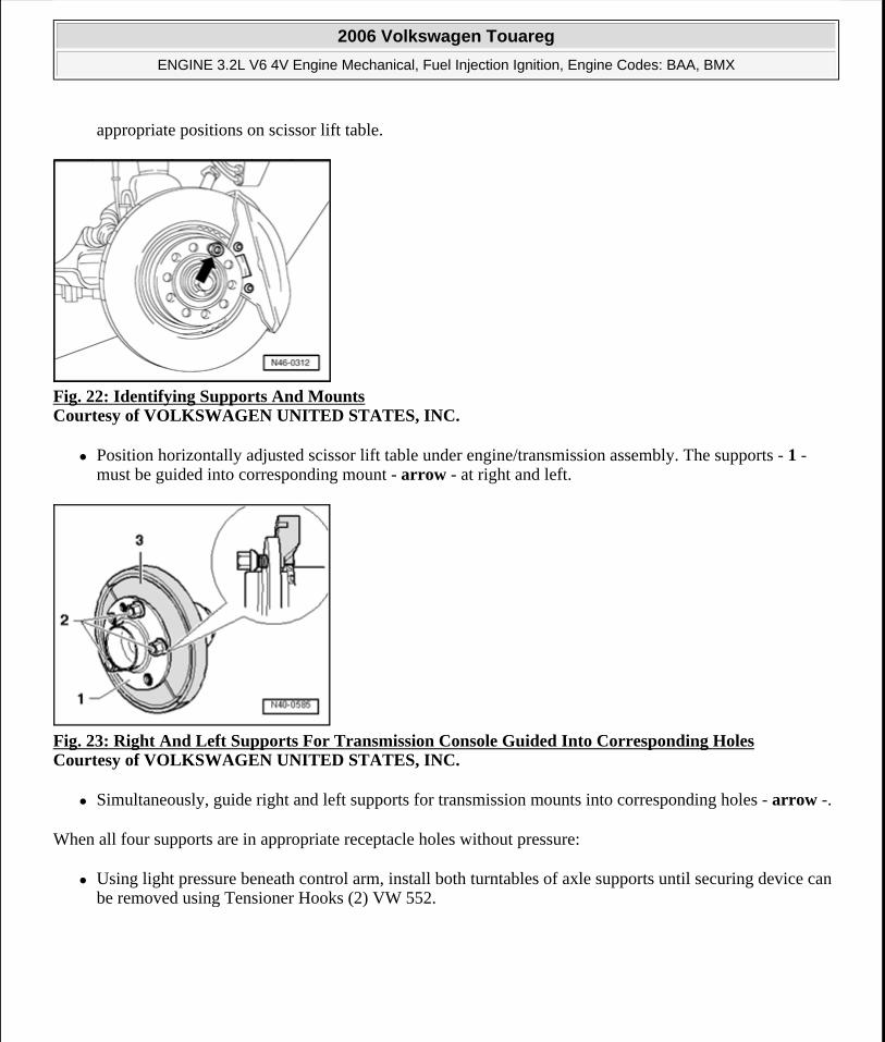
appropriate positions on scissor lift table.
Fig. 22: Identifying Supports And Mounts Courtesy of VOLKSWAGEN UNITED STATES, INC.
Position horizontally adjusted scissor lift table under engine/transmission assembly. The supports - 1 - must be guided into corresponding mount - arrow - at right and left.
Fig. 23: Right And Left Supports For Transmission Console Guided Into Corresponding Holes Courtesy of VOLKSWAGEN UNITED STATES, INC.
Simultaneously, guide right and left supports for transmission mounts into corresponding holes - arrow -.
When all four supports are in appropriate receptacle holes without pressure:
Using light pressure beneath control arm, install both turntables of axle supports until securing device can be removed using Tensioner Hooks (2) VW 552.
2006 Volkswagen Touareg
ENGINE 3.2L V6 4V Engine Mechanical, Fuel Injection Ignition, Engine Codes: BAA, BMX
Microsoft
Sunday, September 20, 2009 9:14:16 AM Page 16 © 2005 Mitchell Repair Information Company, LLC.
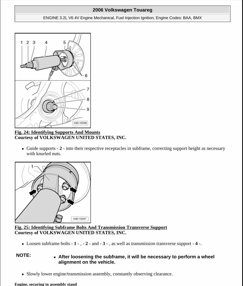
Fig. 24: Identifying Supports And Mounts Courtesy of VOLKSWAGEN UNITED STATES, INC.
Guide supports - 2 - into their respective receptacles in subframe, correcting support height as necessary with knurled nuts.
Fig. 25: Identifying Subframe Bolts And Transmission Transverse Support Courtesy of VOLKSWAGEN UNITED STATES, INC.
Loosen subframe bolts - 1 - , - 2 - and - 3 - , as well as transmission transverse support - 4 -.
Slowly lower engine/transmission assembly, constantly observing clearance.
Engine, securing to assembly stand
NOTE: After loosening the subframe, it will be necessary to perform a wheel alignment on the vehicle.
2006 Volkswagen Touareg
ENGINE 3.2L V6 4V Engine Mechanical, Fuel Injection Ignition, Engine Codes: BAA, BMX
Microsoft
Sunday, September 20, 2009 9:14:16 AM Page 17 © 2005 Mitchell Repair Information Company, LLC.
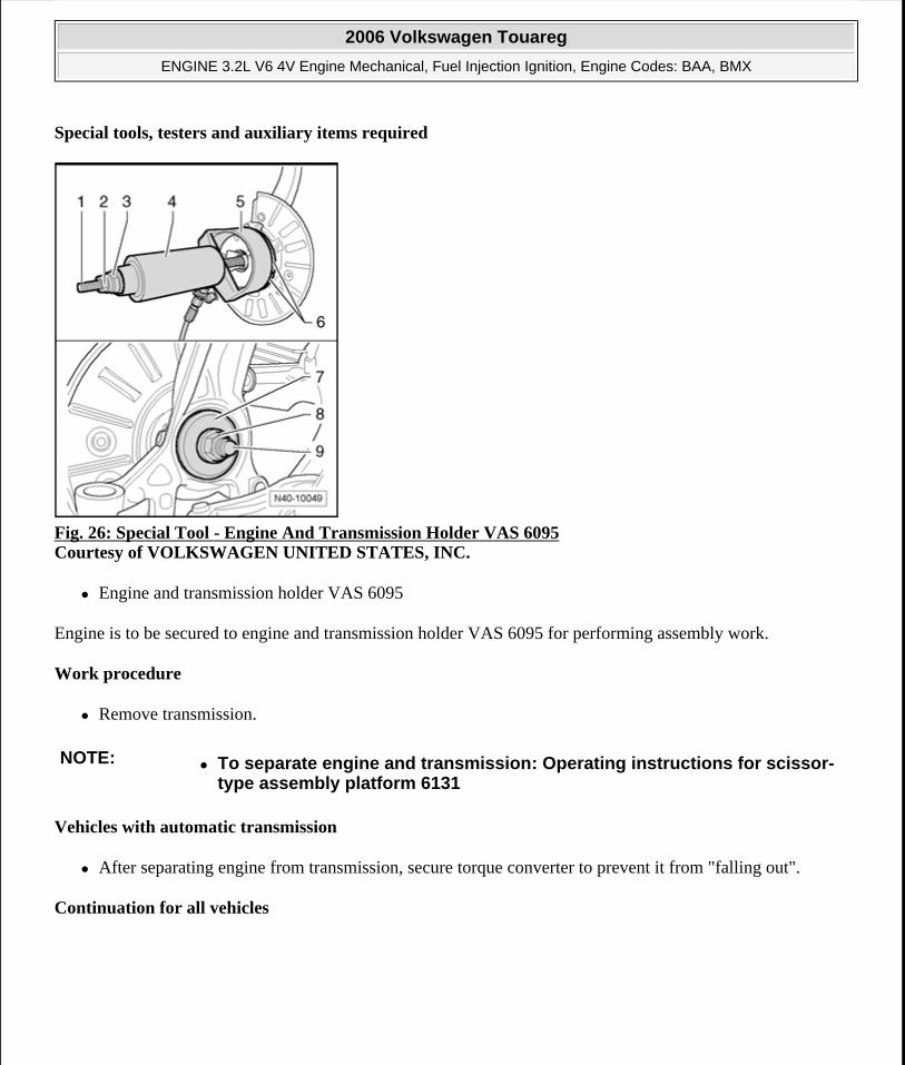
Special tools, testers and auxiliary items required
Fig. 26: Special Tool - Engine And Transmission Holder VAS 6095 Courtesy of VOLKSWAGEN UNITED STATES, INC.
Engine and transmission holder VAS 6095
Engine is to be secured to engine and transmission holder VAS 6095 for performing assembly work.
Work procedure
Remove transmission.
Vehicles with automatic transmission
After separating engine from transmission, secure torque converter to prevent it from "falling out".
Continuation for all vehicles
NOTE: To separate engine and transmission: Operating instructions for scissor-type assembly platform 6131
2006 Volkswagen Touareg
ENGINE 3.2L V6 4V Engine Mechanical, Fuel Injection Ignition, Engine Codes: BAA, BMX
Microsoft
Sunday, September 20, 2009 9:14:16 AM Page 18 © 2005 Mitchell Repair Information Company, LLC.
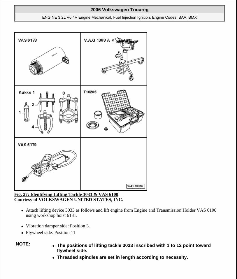
Fig. 27: Identifying Lifting Tackle 3033 & VAS 6100 Courtesy of VOLKSWAGEN UNITED STATES, INC.
Attach lifting device 3033 as follows and lift engine from Engine and Transmission Holder VAS 6100 using workshop hoist 6131.
Vibration damper side: Position 3.
Flywheel side: Position 11
NOTE: The positions of lifting tackle 3033 inscribed with 1 to 12 point toward flywheel side.
Threaded spindles are set in length according to necessity.
2006 Volkswagen Touareg
ENGINE 3.2L V6 4V Engine Mechanical, Fuel Injection Ignition, Engine Codes: BAA, BMX
Microsoft
Sunday, September 20, 2009 9:14:16 AM Page 19 © 2005 Mitchell Repair Information Company, LLC.
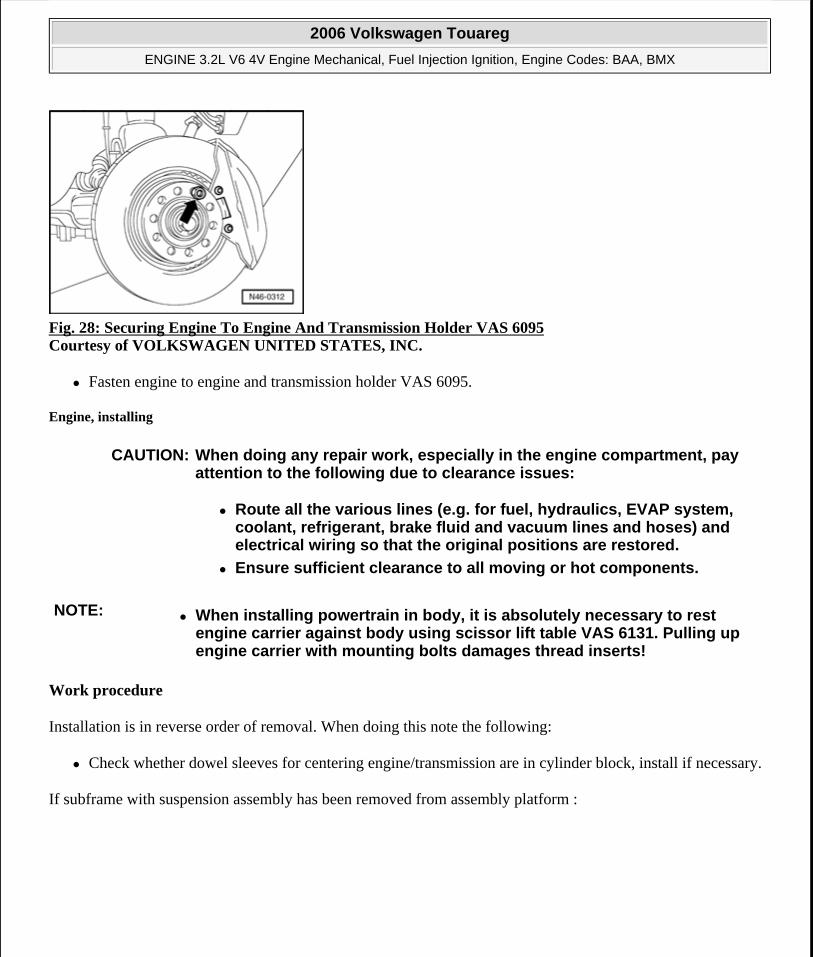
Fig. 28: Securing Engine To Engine And Transmission Holder VAS 6095 Courtesy of VOLKSWAGEN UNITED STATES, INC.
Fasten engine to engine and transmission holder VAS 6095.
Engine, installing
Work procedure
Installation is in reverse order of removal. When doing this note the following:
Check whether dowel sleeves for centering engine/transmission are in cylinder block, install if necessary.
If subframe with suspension assembly has been removed from assembly platform :
CAUTION: When doing any repair work, especially in the engine compartment, pay attention to the following due to clearance issues:
Route all the various lines (e.g. for fuel, hydraulics, EVAP system, coolant, refrigerant, brake fluid and vacuum lines and hoses) and electrical wiring so that the original positions are restored.
Ensure sufficient clearance to all moving or hot components.
NOTE: When installing powertrain in body, it is absolutely necessary to rest engine carrier against body using scissor lift table VAS 6131. Pulling up engine carrier with mounting bolts damages thread inserts!
2006 Volkswagen Touareg
ENGINE 3.2L V6 4V Engine Mechanical, Fuel Injection Ignition, Engine Codes: BAA, BMX
Microsoft
Sunday, September 20, 2009 9:14:16 AM Page 20 © 2005 Mitchell Repair Information Company, LLC.
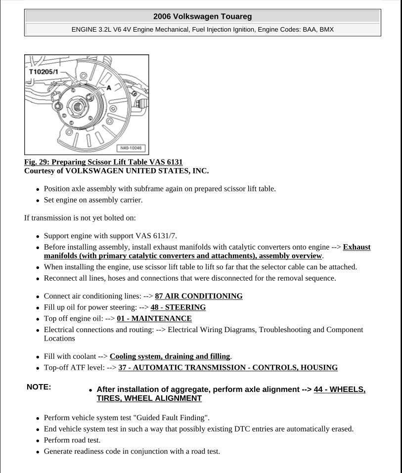
Fig. 29: Preparing Scissor Lift Table VAS 6131 Courtesy of VOLKSWAGEN UNITED STATES, INC.
Position axle assembly with subframe again on prepared scissor lift table.
Set engine on assembly carrier.
If transmission is not yet bolted on:
Support engine with support VAS 6131/7.
Before installing assembly, install exhaust manifolds with catalytic converters onto engine --> Exhaust manifolds (with primary catalytic converters and attachments), assembly overview.
When installing the engine, use scissor lift table to lift so far that the selector cable can be attached.
Reconnect all lines, hoses and connections that were disconnected for the removal sequence.
Connect air conditioning lines: --> 87 AIR CONDITIONING
Fill up oil for power steering: --> 48 - STEERING
Top off engine oil: --> 01 - MAINTENANCE
Electrical connections and routing: --> Electrical Wiring Diagrams, Troubleshooting and Component Locations
Fill with coolant --> Cooling system, draining and filling.
Top-off ATF level: --> 37 - AUTOMATIC TRANSMISSION - CONTROLS, HOUSING
Perform vehicle system test "Guided Fault Finding".
End vehicle system test in such a way that possibly existing DTC entries are automatically erased.
Perform road test.
Generate readiness code in conjunction with a road test.
NOTE: After installation of aggregate, perform axle alignment --> 44 - WHEELS, TIRES, WHEEL ALIGNMENT
2006 Volkswagen Touareg
ENGINE 3.2L V6 4V Engine Mechanical, Fuel Injection Ignition, Engine Codes: BAA, BMX
Microsoft
Sunday, September 20, 2009 9:14:16 AM Page 21 © 2005 Mitchell Repair Information Company, LLC.
After that perform vehicle system test again and repair any occurring malfunctions.
Torque specifications
* Engine bracket and engine mount, removing and installing
13 - ENGINE - CRANKSHAFT, CYLINDER BLOCK
ENGINE, DISASSEMBLING AND ASSEMBLING
Engine, disassembling and assembling
Replace oil spray jets
Replace oil cooler
Replace oil filter.
Chain drive, assembly overview --> Chain drive, assembly overview
Cylinder block, assembly overview --> Cylinder block, assembly overview
NOTE: Observe safety precautions that apply to road tests --> Safety precautions.
Bolted connections Torque specificationsBolts, nuts M6 10 Nm M7 15 Nm M8 25 Nm M10 40 Nm M12 60 NmDeviation from Engine bracket to engine mount (nut) * See note M10 75 NmEngine mount to engine carrier (bolt) * See note M10 60 Nm
Engine carrier to chassis (bolt) M12 100 Nm + 1 /2 turn (180°)
Drive axles to transmission --> 40 - FRONT SUSPENSION
NOTE: Engine is to be secured to engine and transmission holder VAS 6095 for performing assembly work.
If large quantities of metal particles or abraded material are detected during engine repairs, it may be an indication for a damaged crankshaft or rod bearings. To prevent further damage, perform the following steps after the repair:
Thoroughly clean oil passages
Replace oil non-return valve
2006 Volkswagen Touareg
ENGINE 3.2L V6 4V Engine Mechanical, Fuel Injection Ignition, Engine Codes: BAA, BMX
Microsoft
Sunday, September 20, 2009 9:14:16 AM Page 22 © 2005 Mitchell Repair Information Company, LLC.
Engine bracket and left/right engine mounts, removing and installing
Removing and installing ribbed belt --> Ribbed belt, removing and installing
Removing and installing sealing flange and dual-mass flywheel --> Sealing flange and dual-mass flywheel, removing and installing
Removing and installing crankshaft --> Crankshaft, removing and installing
Piston and connecting rod, disassembling and assembling, assembly overview --> Piston and connecting rod, disassembling and assembling
Chain drive, assembly overview
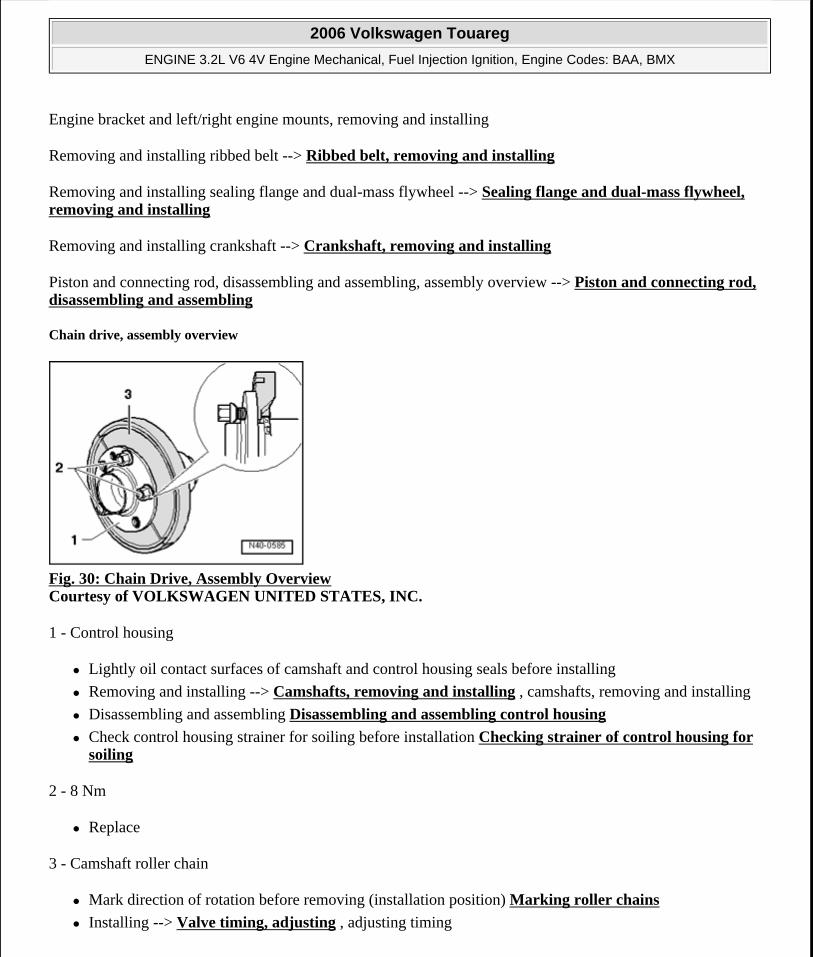
Fig. 30: Chain Drive, Assembly Overview Courtesy of VOLKSWAGEN UNITED STATES, INC.
1 - Control housing
Lightly oil contact surfaces of camshaft and control housing seals before installing
Removing and installing --> Camshafts, removing and installing , camshafts, removing and installing
Disassembling and assembling Disassembling and assembling control housing
Check control housing strainer for soiling before installation Checking strainer of control housing for soiling
2 - 8 Nm
Replace
3 - Camshaft roller chain
Mark direction of rotation before removing (installation position) Marking roller chains
Installing --> Valve timing, adjusting , adjusting timing
2006 Volkswagen Touareg
ENGINE 3.2L V6 4V Engine Mechanical, Fuel Injection Ignition, Engine Codes: BAA, BMX
Microsoft
Sunday, September 20, 2009 9:14:16 AM Page 23 © 2005 Mitchell Repair Information Company, LLC.
4 - Exhaust camshaft adjuster
Identification: 32A
Only rotate engine with camshaft adjuster installed
Installing --> Valve timing, adjusting , adjusting timing
5 - Intermediate shaft
6 - Thrust washer
Not installed on all engines
7 - 8 Nm
Insert using locking fluid D 000 600 A2
8 - Tensioning rail
9 - Pivot pin, 18 Nm
10 - Chain tensioner, 40 Nm
Only rotate engine with chain tensioner installed
11 - Seal
Replace if damaged or leaking
12 - Chain sprocket
Installing --> Valve timing, adjusting , adjusting timing
13 - Chain sprocket
Installing --> Valve timing, adjusting , adjusting timing
14 - 60 Nm plus an additional 1 /4 turn (90°)
Replace
Use counter-holder tool T10069 to tighten and loosen To loosen and tighten securing bolt, lock vibration damper using under Cylinder block, assembly overview
15 - Chain tensioner with tensioning rail
Before installation release locking device in chain tensioner with a small screwdriver and press tensioning
2006 Volkswagen Touareg
ENGINE 3.2L V6 4V Engine Mechanical, Fuel Injection Ignition, Engine Codes: BAA, BMX
Microsoft
Sunday, September 20, 2009 9:14:16 AM Page 24 © 2005 Mitchell Repair Information Company, LLC.
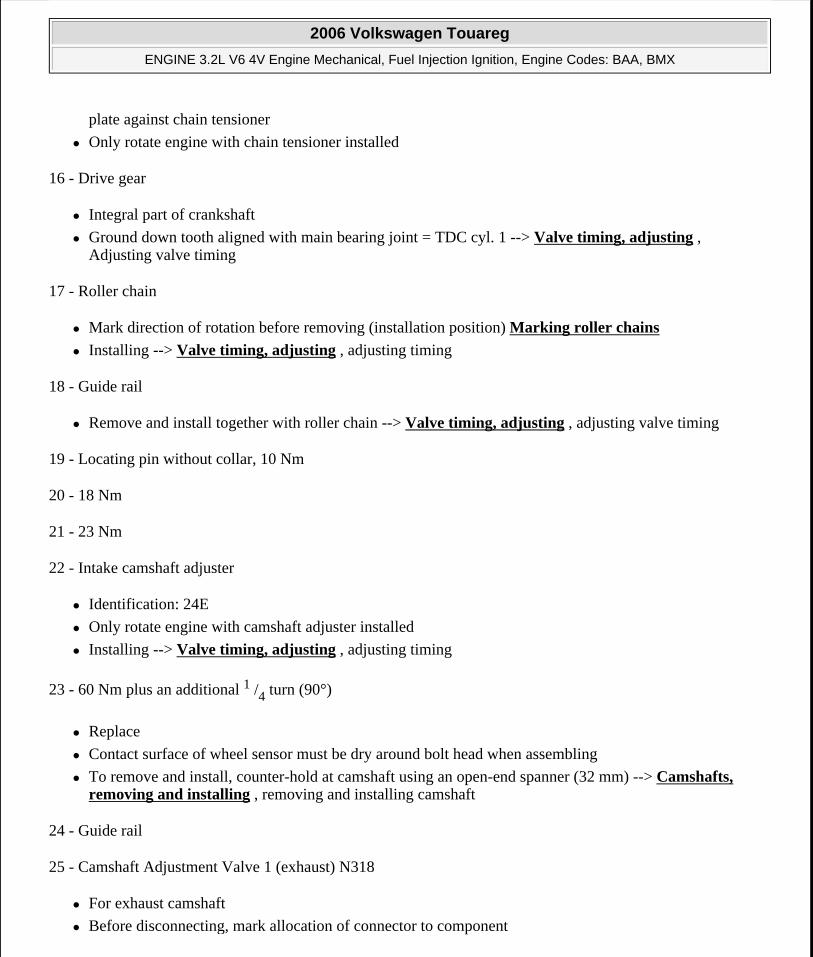
plate against chain tensioner
Only rotate engine with chain tensioner installed
16 - Drive gear
Integral part of crankshaft
Ground down tooth aligned with main bearing joint = TDC cyl. 1 --> Valve timing, adjusting , Adjusting valve timing
17 - Roller chain
Mark direction of rotation before removing (installation position) Marking roller chains
Installing --> Valve timing, adjusting , adjusting timing
18 - Guide rail
Remove and install together with roller chain --> Valve timing, adjusting , adjusting valve timing
19 - Locating pin without collar, 10 Nm
20 - 18 Nm
21 - 23 Nm
22 - Intake camshaft adjuster
Identification: 24E
Only rotate engine with camshaft adjuster installed
Installing --> Valve timing, adjusting , adjusting timing
23 - 60 Nm plus an additional 1 /4 turn (90°)
Replace
Contact surface of wheel sensor must be dry around bolt head when assembling
To remove and install, counter-hold at camshaft using an open-end spanner (32 mm) --> Camshafts, removing and installing , removing and installing camshaft
24 - Guide rail
25 - Camshaft Adjustment Valve 1 (exhaust) N318
For exhaust camshaft
Before disconnecting, mark allocation of connector to component
2006 Volkswagen Touareg
ENGINE 3.2L V6 4V Engine Mechanical, Fuel Injection Ignition, Engine Codes: BAA, BMX
Microsoft
Sunday, September 20, 2009 9:14:16 AM Page 25 © 2005 Mitchell Repair Information Company, LLC.
26 - Camshaft Adjustment Valve 1 N205
For intake camshaft
Before disconnecting, mark allocation of connector to component
27 - Guide rail
Clipped in at control housing
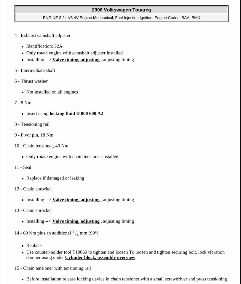
Marking roller chains
Fig. 31: Identifying Markings On Roller Chains Courtesy of VOLKSWAGEN UNITED STATES, INC.
Mark roller chains before removing (e.g. with paint, arrow pointing in direction of rotation).
Cylinder block, assembly overview
Engine bracket and left/right engine mounts, removing and installing
NOTE: Do not mark chain using a center punch or similar means!
2006 Volkswagen Touareg
ENGINE 3.2L V6 4V Engine Mechanical, Fuel Injection Ignition, Engine Codes: BAA, BMX
Microsoft
Sunday, September 20, 2009 9:14:16 AM Page 26 © 2005 Mitchell Repair Information Company, LLC.
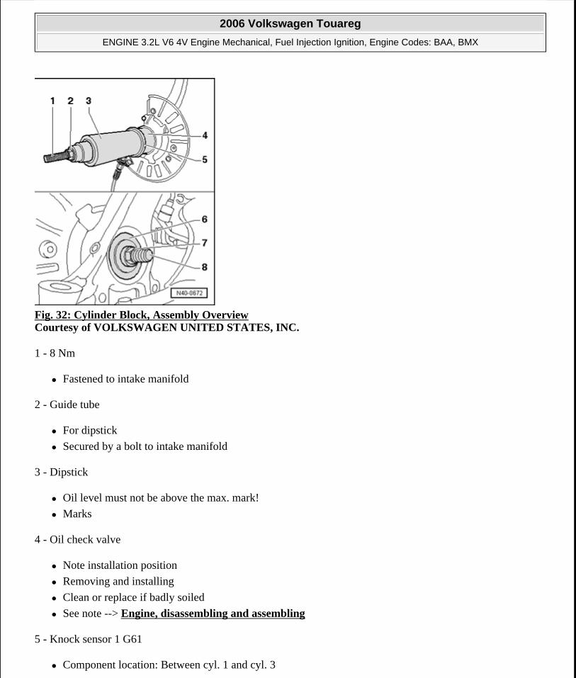
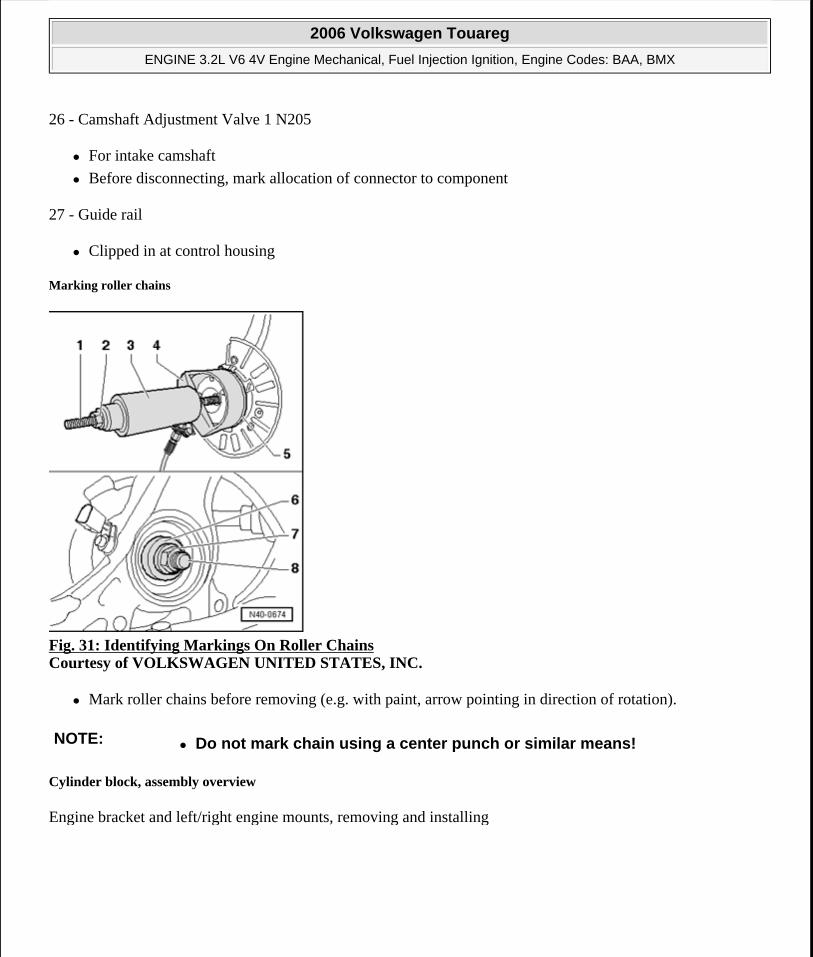
Fig. 32: Cylinder Block, Assembly Overview Courtesy of VOLKSWAGEN UNITED STATES, INC.
1 - 8 Nm
Fastened to intake manifold
2 - Guide tube
For dipstick
Secured by a bolt to intake manifold
3 - Dipstick
Oil level must not be above the max. mark!
Marks
4 - Oil check valve
Note installation position
Removing and installing
Clean or replace if badly soiled
See note --> Engine, disassembling and assembling
5 - Knock sensor 1 G61
Component location: Between cyl. 1 and cyl. 3
2006 Volkswagen Touareg
ENGINE 3.2L V6 4V Engine Mechanical, Fuel Injection Ignition, Engine Codes: BAA, BMX
Microsoft
Sunday, September 20, 2009 9:14:16 AM Page 27 © 2005 Mitchell Repair Information Company, LLC.
6 - 20 Nm
Torque setting influences function of knock sensor
7 - 10 Nm
8 - Oil pump drive cover
9 - O-ring
Replace
Oil before assembling
10 - Oil pump drive
11 - Cylinder block
Removing and installing sealing flange and dual-mass flywheel --> Sealing flange and dual-mass flywheel, removing and installing
Removing and installing crankshaft --> Crankshaft, removing and installing
Piston and connecting rod, disassembling and assembling --> Piston and connecting rod, disassembling and assembling
12 - Intermediate shaft
13 - Thrust washer
Not installed on all engines
14 - 10 Nm
Insert using locking fluid D 000 600 A2
15 - Input shaft
For oil pump drive
16 - Engine speed (RPM) sensor G28
17 - Oil pump
Disassembling and assembling --> Oil pump, disassembling and assembling
18 - 23 Nm
19 - 8 Nm
2006 Volkswagen Touareg
ENGINE 3.2L V6 4V Engine Mechanical, Fuel Injection Ignition, Engine Codes: BAA, BMX
Microsoft
Sunday, September 20, 2009 9:14:16 AM Page 28 © 2005 Mitchell Repair Information Company, LLC.
Insert using locking fluid D 000 600 A2
20 - Oil drain plug, 30 Nm
Replace
21 - Oil pan
Removing and installing --> Oil pan, removing and installing
22 - Oil Level Thermal Sensor G266
Only for vehicles with engine code "AZZ"
23 - Seal
Replace
Oil before assembling
24 - 20 Nm
25 - Seal
Replace
26 - Oil filter housing/left engine bracket
Disassembling and assembling --> Oil filter housing, disassembling and assembling
Coolant hose connection diagram --> Coolant hose connection diagram
Engine bracket and left/right engine mounts, removing
27 - 23 Nm
28 - To thermostat housing
29 - 25 Nm
30 - Fitting bolt, 25 Nm
31 - Compact bracket
For generator, air conditioning compressor, and power steering pump
32 - Coolant line
2006 Volkswagen Touareg
ENGINE 3.2L V6 4V Engine Mechanical, Fuel Injection Ignition, Engine Codes: BAA, BMX
Microsoft
Sunday, September 20, 2009 9:14:16 AM Page 29 © 2005 Mitchell Repair Information Company, LLC.
Removing and installing --> Cooling system components (on engine), assembly overview , components of cooling system - engine side
33 - Knock sensor 2 G66
Component location: Between cyl. 4 and cyl. 6
34 - Vibration damper
Removing and installing ribbed belt --> Ribbed belt, removing and installing
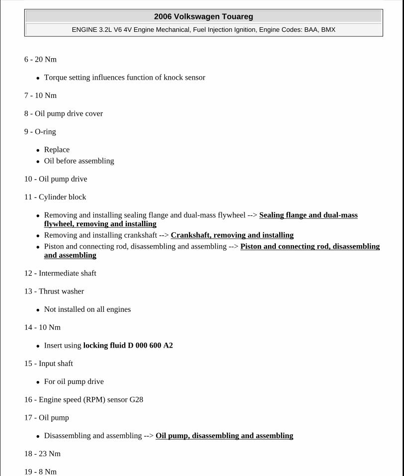
35 - 100 Nm plus an additional 1 /2 turn (180°)
Replace
Use counter-holder tool T10069 for loosening and tightening To loosen and tighten securing bolt, lock vibration damper using under Cylinder block, assembly overview
Tighten using torque wrench V.A.G 1601
Fig. 33: Loosening/Tightening Securing Bolt, Using Counter-Holder T10069 To Hold Vibration DamperCourtesy of VOLKSWAGEN UNITED STATES, INC.
To loosen and tighten securing bolt, lock vibration damper using counter-holder tool T10069
Engine bracket and left/right engine mounts, removing and installing
NOTE: Vibration damper securing bolt must be replaced.
Tighten securing bolt using torque wrench V.A.G 1601.
2006 Volkswagen Touareg
ENGINE 3.2L V6 4V Engine Mechanical, Fuel Injection Ignition, Engine Codes: BAA, BMX
Microsoft
Sunday, September 20, 2009 9:14:16 AM Page 30 © 2005 Mitchell Repair Information Company, LLC.
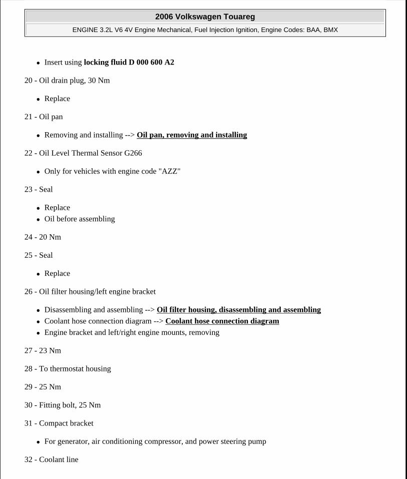
Special tools, testers and auxiliary items required
Engine support bridge 10 - 222 A
Shackle 10 - 222 A/12
Adapter 10 - 222 A/16
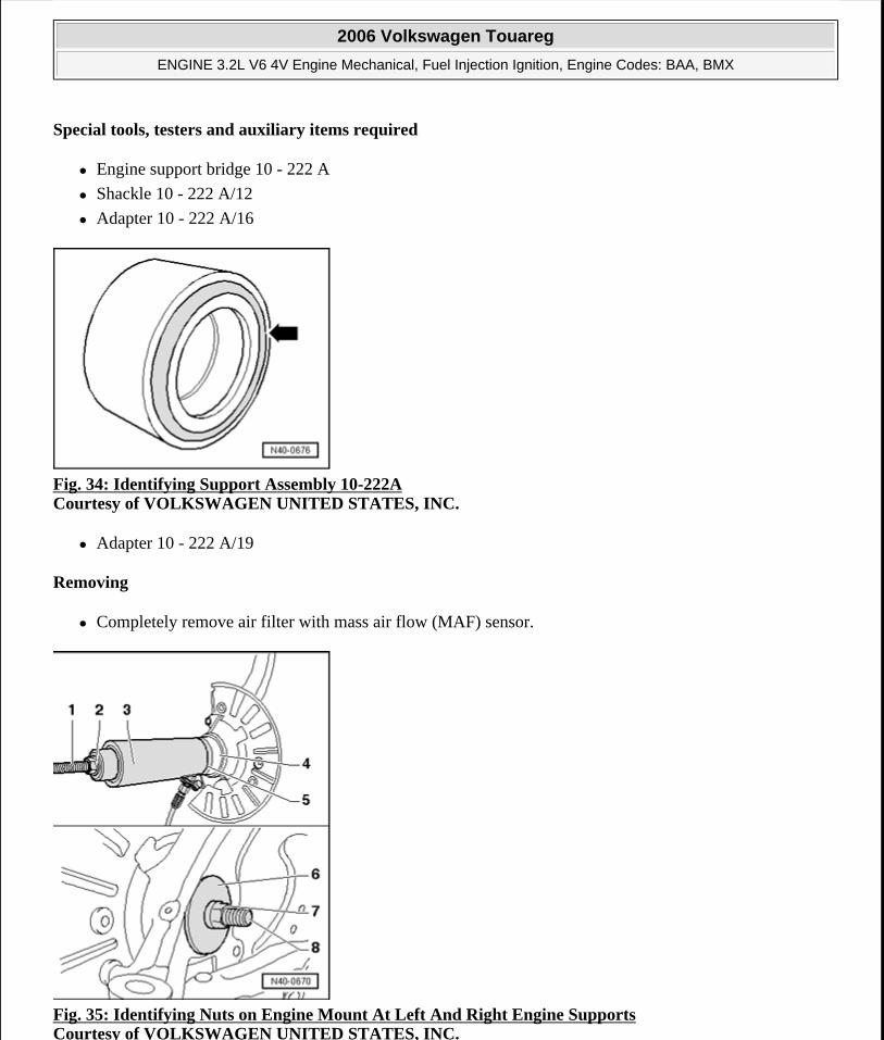
Fig. 34: Identifying Support Assembly 10-222A Courtesy of VOLKSWAGEN UNITED STATES, INC.
Adapter 10 - 222 A/19
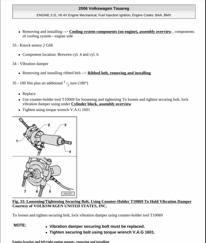
Removing
Completely remove air filter with mass air flow (MAF) sensor.
Fig. 35: Identifying Nuts on Engine Mount At Left And Right Engine Supports Courtesy of VOLKSWAGEN UNITED STATES, INC.
2006 Volkswagen Touareg
ENGINE 3.2L V6 4V Engine Mechanical, Fuel Injection Ignition, Engine Codes: BAA, BMX
Microsoft
Sunday, September 20, 2009 9:14:16 AM Page 31 © 2005 Mitchell Repair Information Company, LLC.
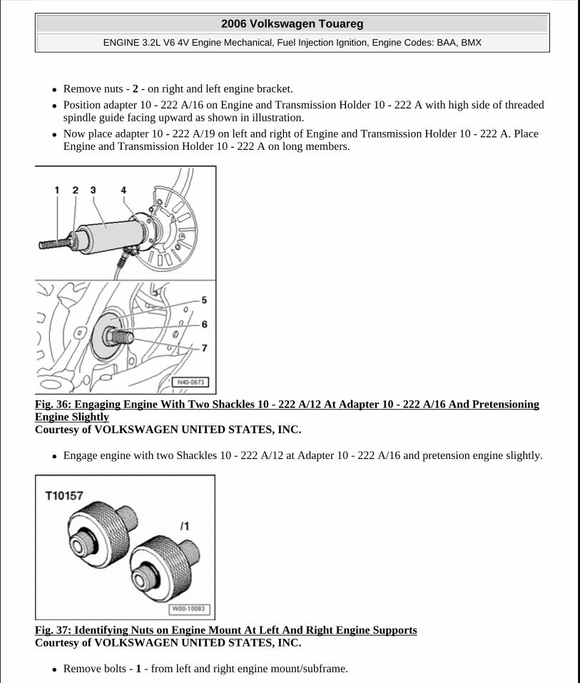
Remove nuts - 2 - on right and left engine bracket.
Position adapter 10 - 222 A/16 on Engine and Transmission Holder 10 - 222 A with high side of threaded spindle guide facing upward as shown in illustration.
Now place adapter 10 - 222 A/19 on left and right of Engine and Transmission Holder 10 - 222 A. Place Engine and Transmission Holder 10 - 222 A on long members.
Fig. 36: Engaging Engine With Two Shackles 10 - 222 A/12 At Adapter 10 - 222 A/16 And Pretensioning Engine Slightly Courtesy of VOLKSWAGEN UNITED STATES, INC.
Engage engine with two Shackles 10 - 222 A/12 at Adapter 10 - 222 A/16 and pretension engine slightly.
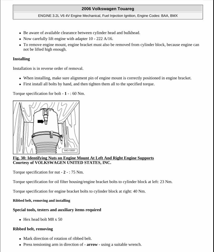
Fig. 37: Identifying Nuts on Engine Mount At Left And Right Engine Supports Courtesy of VOLKSWAGEN UNITED STATES, INC.
Remove bolts - 1 - from left and right engine mount/subframe.
2006 Volkswagen Touareg
ENGINE 3.2L V6 4V Engine Mechanical, Fuel Injection Ignition, Engine Codes: BAA, BMX
Microsoft
Sunday, September 20, 2009 9:14:16 AM Page 32 © 2005 Mitchell Repair Information Company, LLC.
Be aware of available clearance between cylinder head and bulkhead.
Now carefully lift engine with adapter 10 - 222 A/16.
To remove engine mount, engine bracket must also be removed from cylinder block, because engine can not be lifted high enough.
Installing
Installation is in reverse order of removal.
When installing, make sure alignment pin of engine mount is correctly positioned in engine bracket.
First install all bolts by hand, and then tighten them all to the specified torque.
Torque specification for bolt - 1 - : 60 Nm.
Fig. 38: Identifying Nuts on Engine Mount At Left And Right Engine Supports Courtesy of VOLKSWAGEN UNITED STATES, INC.
Torque specification for nut - 2 - : 75 Nm.
Torque specification for oil filter housing/engine bracket bolts to cylinder block at left: 23 Nm.
Torque specification for engine bracket bolts to cylinder block at right: 40 Nm.
Ribbed belt, removing and installing
Special tools, testers and auxiliary items required
Hex head bolt M8 x 50
Ribbed belt, removing
Mark direction of rotation of ribbed belt.
Press tensioning arm in direction of - arrow - using a suitable wrench.
2006 Volkswagen Touareg
ENGINE 3.2L V6 4V Engine Mechanical, Fuel Injection Ignition, Engine Codes: BAA, BMX
Microsoft
Sunday, September 20, 2009 9:14:16 AM Page 33 © 2005 Mitchell Repair Information Company, LLC.
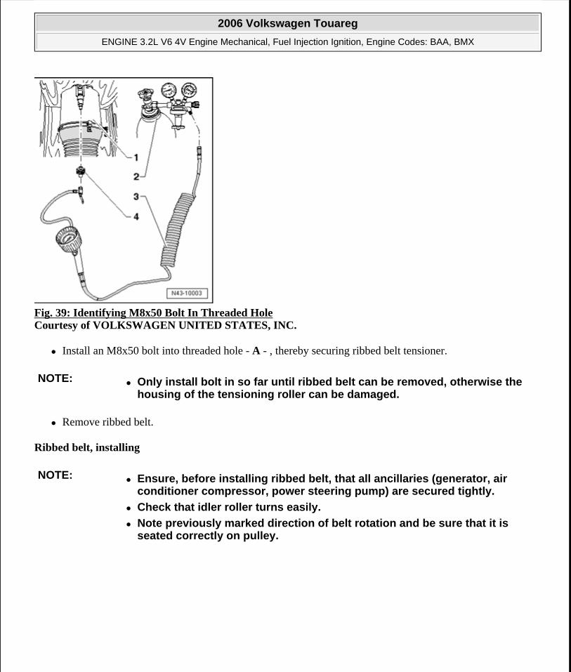
Fig. 39: Identifying M8x50 Bolt In Threaded Hole Courtesy of VOLKSWAGEN UNITED STATES, INC.
Install an M8x50 bolt into threaded hole - A - , thereby securing ribbed belt tensioner.
Remove ribbed belt.
Ribbed belt, installing
NOTE: Only install bolt in so far until ribbed belt can be removed, otherwise the housing of the tensioning roller can be damaged.
NOTE: Ensure, before installing ribbed belt, that all ancillaries (generator, air conditioner compressor, power steering pump) are secured tightly.
Check that idler roller turns easily.
Note previously marked direction of belt rotation and be sure that it is seated correctly on pulley.
2006 Volkswagen Touareg
ENGINE 3.2L V6 4V Engine Mechanical, Fuel Injection Ignition, Engine Codes: BAA, BMX
Microsoft
Sunday, September 20, 2009 9:14:16 AM Page 34 © 2005 Mitchell Repair Information Company, LLC.
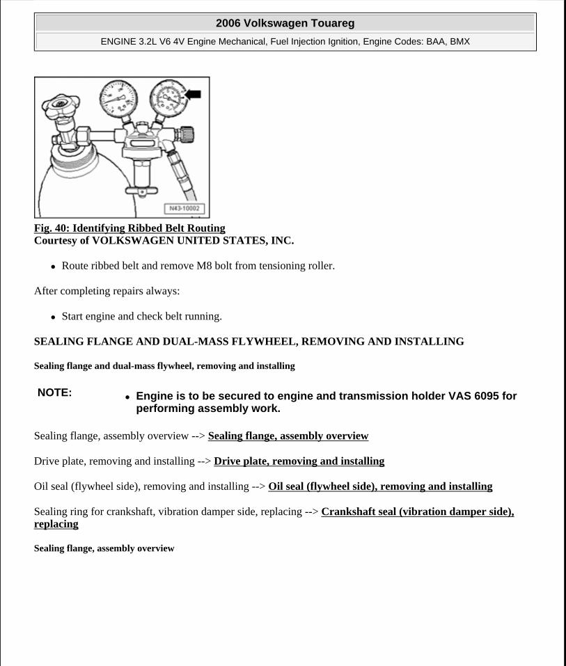
Fig. 40: Identifying Ribbed Belt Routing Courtesy of VOLKSWAGEN UNITED STATES, INC.
Route ribbed belt and remove M8 bolt from tensioning roller.
After completing repairs always:
Start engine and check belt running.
SEALING FLANGE AND DUAL-MASS FLYWHEEL, REMOVING AND INSTALLING
Sealing flange and dual-mass flywheel, removing and installing
Sealing flange, assembly overview --> Sealing flange, assembly overview
Drive plate, removing and installing --> Drive plate, removing and installing
Oil seal (flywheel side), removing and installing --> Oil seal (flywheel side), removing and installing
Sealing ring for crankshaft, vibration damper side, replacing --> Crankshaft seal (vibration damper side), replacing
Sealing flange, assembly overview
NOTE: Engine is to be secured to engine and transmission holder VAS 6095 for performing assembly work.
2006 Volkswagen Touareg
ENGINE 3.2L V6 4V Engine Mechanical, Fuel Injection Ignition, Engine Codes: BAA, BMX
Microsoft
Sunday, September 20, 2009 9:14:16 AM Page 35 © 2005 Mitchell Repair Information Company, LLC.
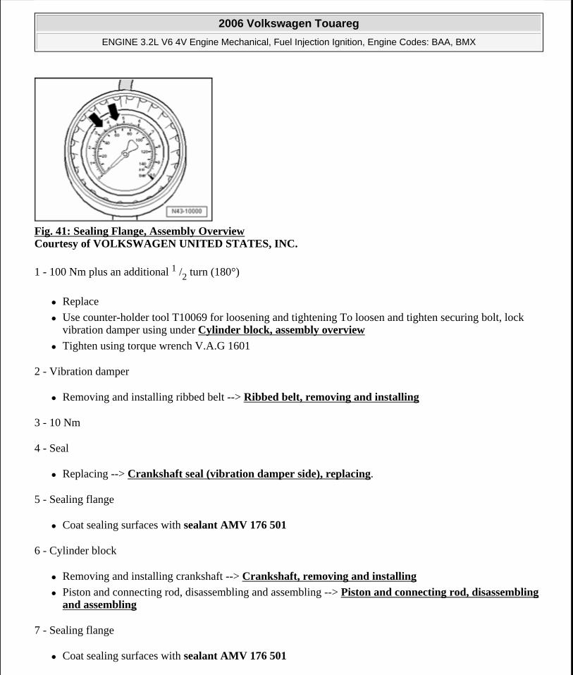
Fig. 41: Sealing Flange, Assembly Overview Courtesy of VOLKSWAGEN UNITED STATES, INC.
1 - 100 Nm plus an additional 1 /2 turn (180°)
Replace
Use counter-holder tool T10069 for loosening and tightening To loosen and tighten securing bolt, lock vibration damper using under Cylinder block, assembly overview
Tighten using torque wrench V.A.G 1601
2 - Vibration damper
Removing and installing ribbed belt --> Ribbed belt, removing and installing
3 - 10 Nm
4 - Seal
Replacing --> Crankshaft seal (vibration damper side), replacing.
5 - Sealing flange
Coat sealing surfaces with sealant AMV 176 501
6 - Cylinder block
Removing and installing crankshaft --> Crankshaft, removing and installing
Piston and connecting rod, disassembling and assembling --> Piston and connecting rod, disassembling and assembling
7 - Sealing flange
Coat sealing surfaces with sealant AMV 176 501
2006 Volkswagen Touareg
ENGINE 3.2L V6 4V Engine Mechanical, Fuel Injection Ignition, Engine Codes: BAA, BMX
Microsoft
Sunday, September 20, 2009 9:14:16 AM Page 36 © 2005 Mitchell Repair Information Company, LLC.
8 - Seal
Remove using pulling hook T20143/2
PTFE version of oil seal
Identification: No inner coil spring
Do not additionally oil or grease sealing lip of sealing ring
Before installing, remove oil remains from crankshaft journal with a clean cloth
Replacing --> Oil seal (flywheel side), removing and installing.
9 - Dual mass flywheel
10 - 60 Nm plus an additional 1 /4 turn (90°)
Replace
To loosen or tighten, use counter-hold T10044 (with 5 mm spacers), or counter-hold T10069.
11 - 25 Nm
Drive plate, removing and installing
Special tools, testers and auxiliary items required
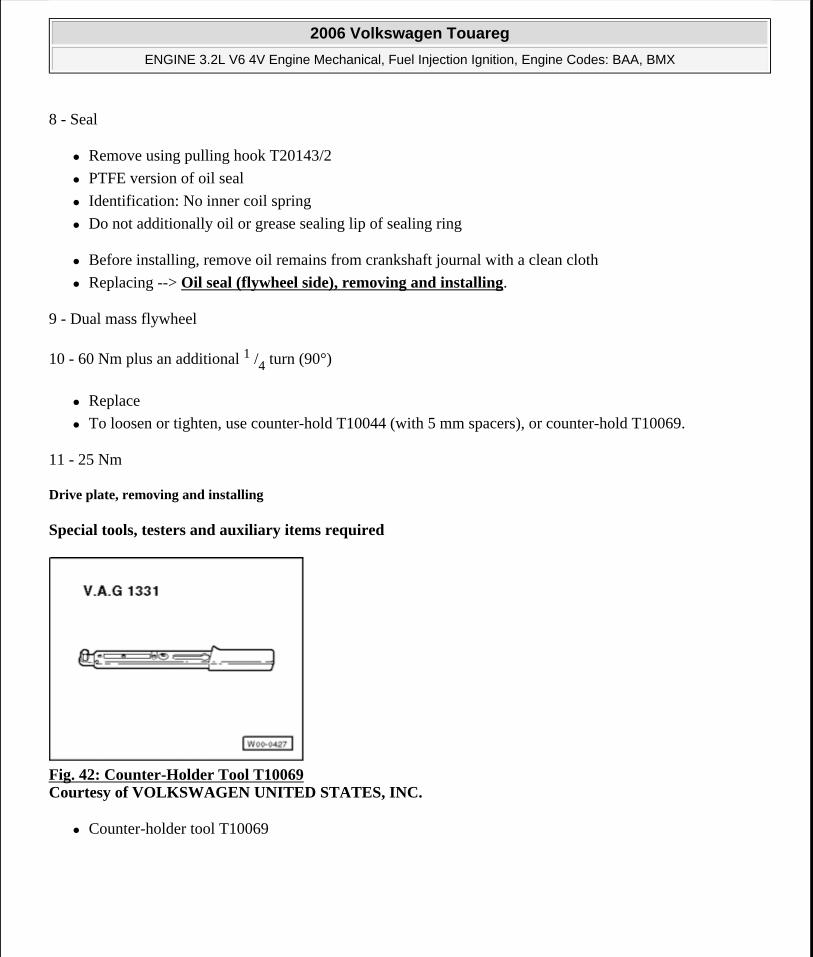
Fig. 42: Counter-Holder Tool T10069 Courtesy of VOLKSWAGEN UNITED STATES, INC.
Counter-holder tool T10069
2006 Volkswagen Touareg
ENGINE 3.2L V6 4V Engine Mechanical, Fuel Injection Ignition, Engine Codes: BAA, BMX
Microsoft
Sunday, September 20, 2009 9:14:16 AM Page 37 © 2005 Mitchell Repair Information Company, LLC.
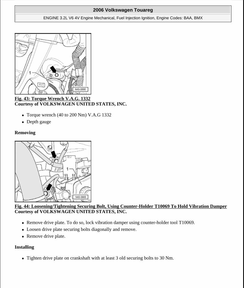
Fig. 43: Torque Wrench V.A.G. 1332 Courtesy of VOLKSWAGEN UNITED STATES, INC.
Torque wrench (40 to 200 Nm) V.A.G 1332
Depth gauge
Removing
Fig. 44: Loosening/Tightening Securing Bolt, Using Counter-Holder T10069 To Hold Vibration DamperCourtesy of VOLKSWAGEN UNITED STATES, INC.
Remove drive plate. To do so, lock vibration damper using counter-holder tool T10069.
Loosen drive plate securing bolts diagonally and remove.
Remove drive plate.
Installing
Tighten drive plate on crankshaft with at least 3 old securing bolts to 30 Nm.
2006 Volkswagen Touareg
ENGINE 3.2L V6 4V Engine Mechanical, Fuel Injection Ignition, Engine Codes: BAA, BMX
Microsoft
Sunday, September 20, 2009 9:14:16 AM Page 38 © 2005 Mitchell Repair Information Company, LLC.
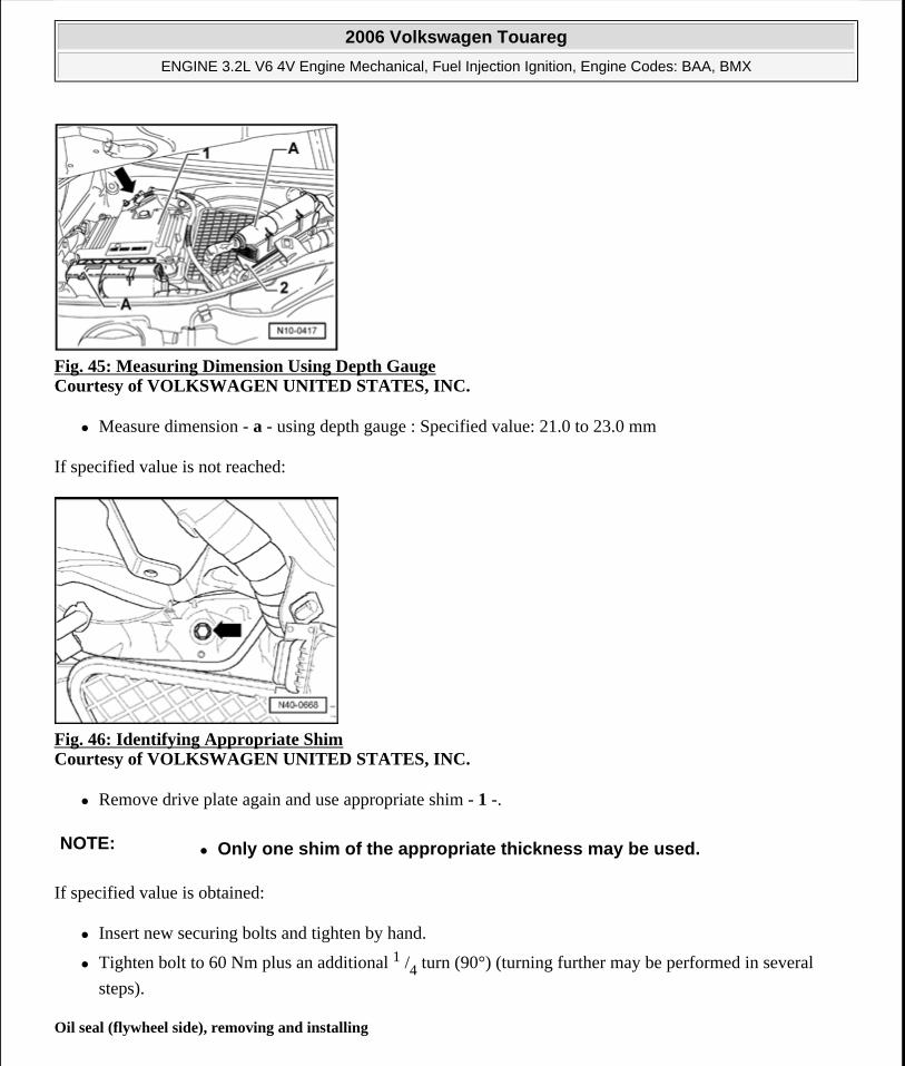
Fig. 45: Measuring Dimension Using Depth Gauge Courtesy of VOLKSWAGEN UNITED STATES, INC.
Measure dimension - a - using depth gauge : Specified value: 21.0 to 23.0 mm
If specified value is not reached:
Fig. 46: Identifying Appropriate Shim Courtesy of VOLKSWAGEN UNITED STATES, INC.
Remove drive plate again and use appropriate shim - 1 -.
If specified value is obtained:
Insert new securing bolts and tighten by hand.
Tighten bolt to 60 Nm plus an additional 1 /4 turn (90°) (turning further may be performed in several
steps).
Oil seal (flywheel side), removing and installing
NOTE: Only one shim of the appropriate thickness may be used.
2006 Volkswagen Touareg
ENGINE 3.2L V6 4V Engine Mechanical, Fuel Injection Ignition, Engine Codes: BAA, BMX
Microsoft
Sunday, September 20, 2009 9:14:16 AM Page 39 © 2005 Mitchell Repair Information Company, LLC.
Special tools, testers and auxiliary items required
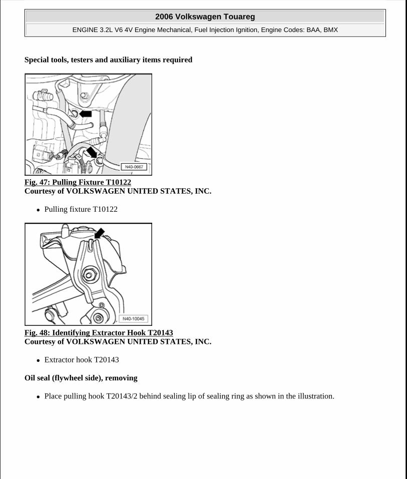
Fig. 47: Pulling Fixture T10122 Courtesy of VOLKSWAGEN UNITED STATES, INC.
Pulling fixture T10122
Fig. 48: Identifying Extractor Hook T20143 Courtesy of VOLKSWAGEN UNITED STATES, INC.
Extractor hook T20143
Oil seal (flywheel side), removing
Place pulling hook T20143/2 behind sealing lip of sealing ring as shown in the illustration.
2006 Volkswagen Touareg
ENGINE 3.2L V6 4V Engine Mechanical, Fuel Injection Ignition, Engine Codes: BAA, BMX
Microsoft
Sunday, September 20, 2009 9:14:16 AM Page 40 © 2005 Mitchell Repair Information Company, LLC.
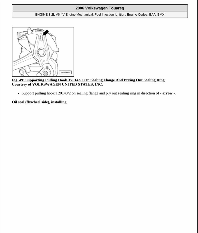
Fig. 49: Supporting Pulling Hook T20143/2 On Sealing Flange And Prying Out Sealing Ring Courtesy of VOLKSWAGEN UNITED STATES, INC.
Support pulling hook T20143/2 on sealing flange and pry out sealing ring in direction of - arrow -.
Oil seal (flywheel side), installing
2006 Volkswagen Touareg
ENGINE 3.2L V6 4V Engine Mechanical, Fuel Injection Ignition, Engine Codes: BAA, BMX
Microsoft
Sunday, September 20, 2009 9:14:16 AM Page 41 © 2005 Mitchell Repair Information Company, LLC.
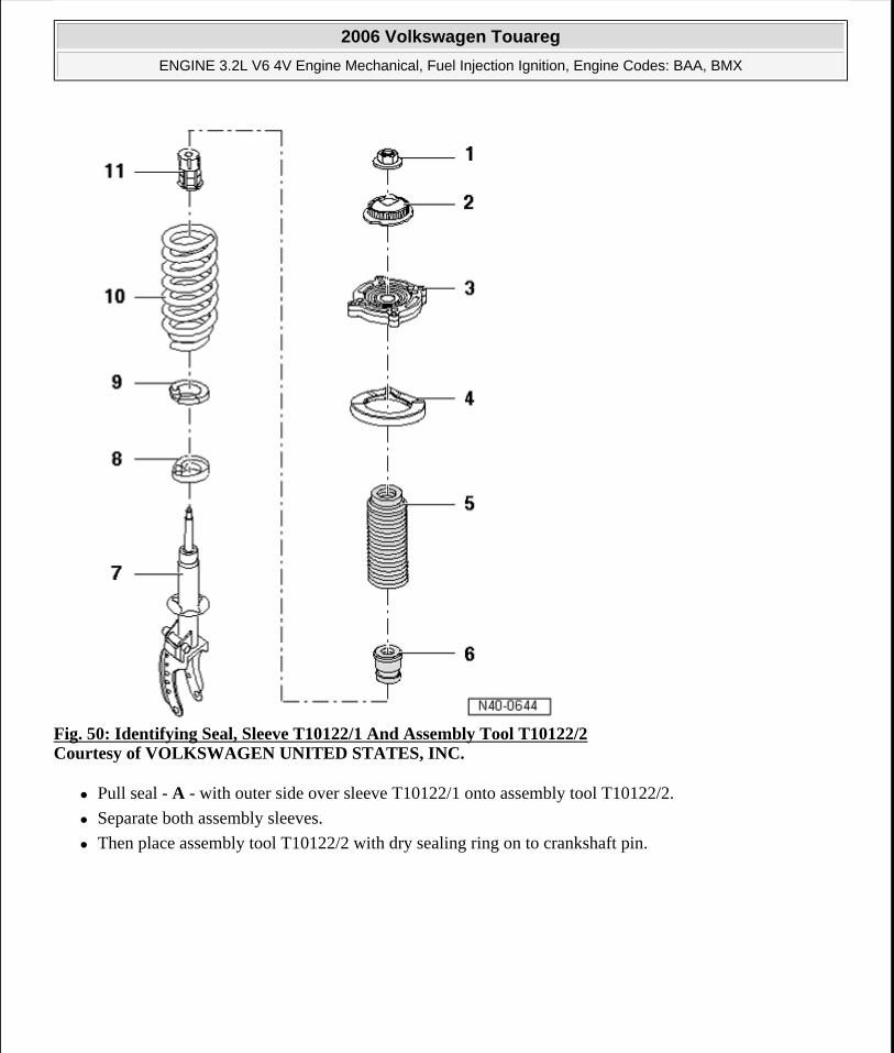
Fig. 50: Identifying Seal, Sleeve T10122/1 And Assembly Tool T10122/2 Courtesy of VOLKSWAGEN UNITED STATES, INC.
Pull seal - A - with outer side over sleeve T10122/1 onto assembly tool T10122/2.
Separate both assembly sleeves.
Then place assembly tool T10122/2 with dry sealing ring on to crankshaft pin.
2006 Volkswagen Touareg
ENGINE 3.2L V6 4V Engine Mechanical, Fuel Injection Ignition, Engine Codes: BAA, BMX
Microsoft
Sunday, September 20, 2009 9:14:16 AM Page 42 © 2005 Mitchell Repair Information Company, LLC.
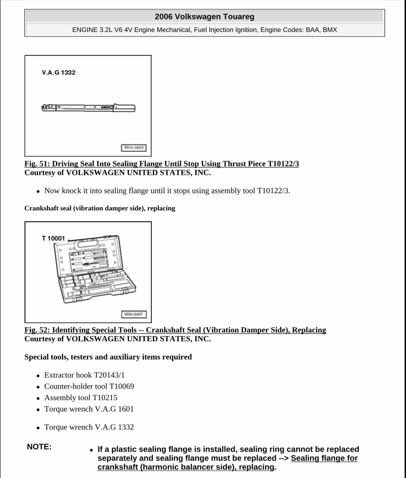
Fig. 51: Driving Seal Into Sealing Flange Until Stop Using Thrust Piece T10122/3 Courtesy of VOLKSWAGEN UNITED STATES, INC.
Now knock it into sealing flange until it stops using assembly tool T10122/3.
Crankshaft seal (vibration damper side), replacing
Fig. 52: Identifying Special Tools -- Crankshaft Seal (Vibration Damper Side), Replacing Courtesy of VOLKSWAGEN UNITED STATES, INC.
Special tools, testers and auxiliary items required
Extractor hook T20143/1
Counter-holder tool T10069
Assembly tool T10215
Torque wrench V.A.G 1601
Torque wrench V.A.G 1332
NOTE: If a plastic sealing flange is installed, sealing ring cannot be replaced separately and sealing flange must be replaced --> Sealing flange for crankshaft (harmonic balancer side), replacing.
2006 Volkswagen Touareg
ENGINE 3.2L V6 4V Engine Mechanical, Fuel Injection Ignition, Engine Codes: BAA, BMX
Microsoft
Sunday, September 20, 2009 9:14:16 AM Page 43 © 2005 Mitchell Repair Information Company, LLC.
Removing
Bring lock carrier into service position --> 50 - BODY - FRONT .
Remove ribbed belt --> Ribbed belt, removing and installing.
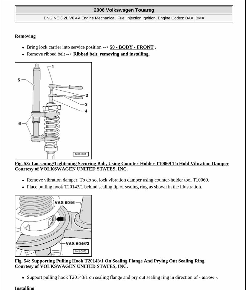
Fig. 53: Loosening/Tightening Securing Bolt, Using Counter-Holder T10069 To Hold Vibration DamperCourtesy of VOLKSWAGEN UNITED STATES, INC.
Remove vibration damper. To do so, lock vibration damper using counter-holder tool T10069.
Place pulling hook T20143/1 behind sealing lip of sealing ring as shown in the illustration.
Fig. 54: Supporting Pulling Hook T20143/1 On Sealing Flange And Prying Out Sealing Ring Courtesy of VOLKSWAGEN UNITED STATES, INC.
Support pulling hook T20143/1 on sealing flange and pry out sealing ring in direction of - arrow -.
Installing
2006 Volkswagen Touareg
ENGINE 3.2L V6 4V Engine Mechanical, Fuel Injection Ignition, Engine Codes: BAA, BMX
Microsoft
Sunday, September 20, 2009 9:14:16 AM Page 44 © 2005 Mitchell Repair Information Company, LLC.
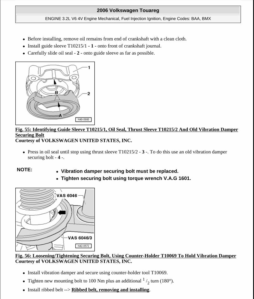
Before installing, remove oil remains from end of crankshaft with a clean cloth.
Install guide sleeve T10215/1 - 1 - onto front of crankshaft journal.
Carefully slide oil seal - 2 - onto guide sleeve as far as possible.
Fig. 55: Identifying Guide Sleeve T10215/1, Oil Seal, Thrust Sleeve T10215/2 And Old Vibration Damper Securing Bolt Courtesy of VOLKSWAGEN UNITED STATES, INC.
Press in oil seal until stop using thrust sleeve T10215/2 - 3 -. To do this use an old vibration damper securing bolt - 4 -.
Fig. 56: Loosening/Tightening Securing Bolt, Using Counter-Holder T10069 To Hold Vibration DamperCourtesy of VOLKSWAGEN UNITED STATES, INC.
Install vibration damper and secure using counter-holder tool T10069.
Tighten new mounting bolt to 100 Nm plus an additional 1 /2 turn (180°).
Install ribbed belt --> Ribbed belt, removing and installing.
NOTE: Vibration damper securing bolt must be replaced.
Tighten securing bolt using torque wrench V.A.G 1601.
2006 Volkswagen Touareg
ENGINE 3.2L V6 4V Engine Mechanical, Fuel Injection Ignition, Engine Codes: BAA, BMX
Microsoft
Sunday, September 20, 2009 9:14:16 AM Page 45 © 2005 Mitchell Repair Information Company, LLC.
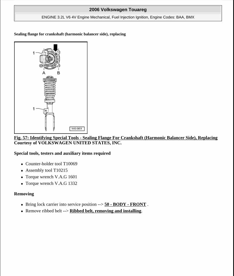
Sealing flange for crankshaft (harmonic balancer side), replacing
Fig. 57: Identifying Special Tools - Sealing Flange For Crankshaft (Harmonic Balancer Side), ReplacingCourtesy of VOLKSWAGEN UNITED STATES, INC.
Special tools, testers and auxiliary items required
Counter-holder tool T10069
Assembly tool T10215
Torque wrench V.A.G 1601
Torque wrench V.A.G 1332
Removing
Bring lock carrier into service position --> 50 - BODY - FRONT .
Remove ribbed belt --> Ribbed belt, removing and installing.
2006 Volkswagen Touareg
ENGINE 3.2L V6 4V Engine Mechanical, Fuel Injection Ignition, Engine Codes: BAA, BMX
Microsoft
Sunday, September 20, 2009 9:14:16 AM Page 46 © 2005 Mitchell Repair Information Company, LLC.
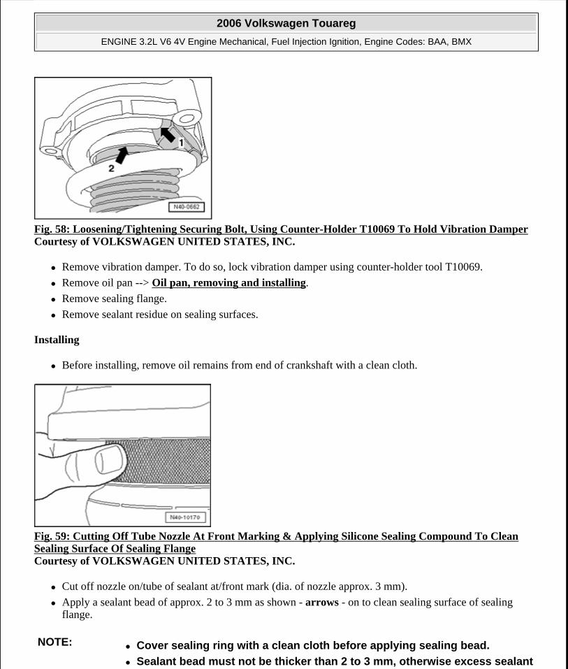
Fig. 58: Loosening/Tightening Securing Bolt, Using Counter-Holder T10069 To Hold Vibration DamperCourtesy of VOLKSWAGEN UNITED STATES, INC.
Remove vibration damper. To do so, lock vibration damper using counter-holder tool T10069.
Remove oil pan --> Oil pan, removing and installing.
Remove sealing flange.
Remove sealant residue on sealing surfaces.
Installing
Before installing, remove oil remains from end of crankshaft with a clean cloth.
Fig. 59: Cutting Off Tube Nozzle At Front Marking & Applying Silicone Sealing Compound To Clean Sealing Surface Of Sealing Flange Courtesy of VOLKSWAGEN UNITED STATES, INC.
Cut off nozzle on/tube of sealant at/front mark (dia. of nozzle approx. 3 mm).
Apply a sealant bead of approx. 2 to 3 mm as shown - arrows - on to clean sealing surface of sealing flange.
NOTE: Cover sealing ring with a clean cloth before applying sealing bead.
Sealant bead must not be thicker than 2 to 3 mm, otherwise excess sealant
2006 Volkswagen Touareg
ENGINE 3.2L V6 4V Engine Mechanical, Fuel Injection Ignition, Engine Codes: BAA, BMX
Microsoft
Sunday, September 20, 2009 9:14:16 AM Page 47 © 2005 Mitchell Repair Information Company, LLC.
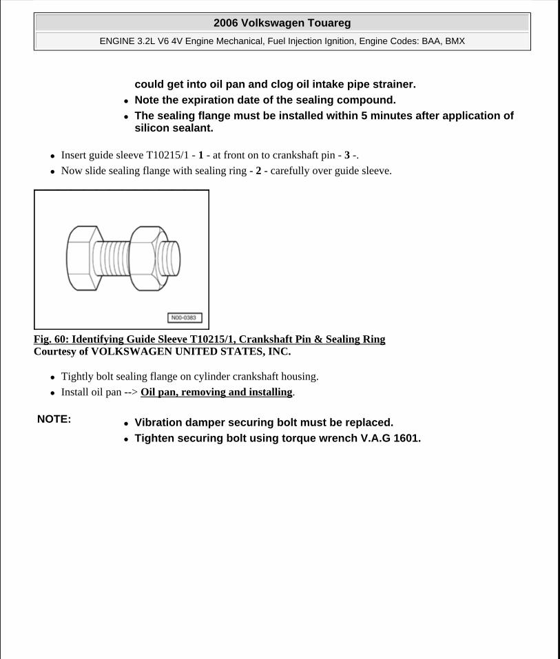
Insert guide sleeve T10215/1 - 1 - at front on to crankshaft pin - 3 -.
Now slide sealing flange with sealing ring - 2 - carefully over guide sleeve.
Fig. 60: Identifying Guide Sleeve T10215/1, Crankshaft Pin & Sealing Ring Courtesy of VOLKSWAGEN UNITED STATES, INC.
Tightly bolt sealing flange on cylinder crankshaft housing.
Install oil pan --> Oil pan, removing and installing.
could get into oil pan and clog oil intake pipe strainer.
Note the expiration date of the sealing compound.
The sealing flange must be installed within 5 minutes after application of silicon sealant.
NOTE: Vibration damper securing bolt must be replaced.
Tighten securing bolt using torque wrench V.A.G 1601.
2006 Volkswagen Touareg
ENGINE 3.2L V6 4V Engine Mechanical, Fuel Injection Ignition, Engine Codes: BAA, BMX
Microsoft
Sunday, September 20, 2009 9:14:16 AM Page 48 © 2005 Mitchell Repair Information Company, LLC.
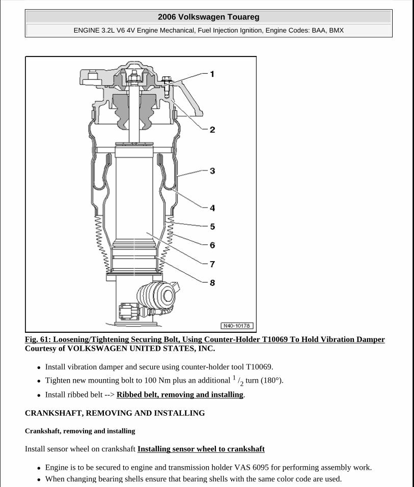
Fig. 61: Loosening/Tightening Securing Bolt, Using Counter-Holder T10069 To Hold Vibration DamperCourtesy of VOLKSWAGEN UNITED STATES, INC.
Install vibration damper and secure using counter-holder tool T10069.
Tighten new mounting bolt to 100 Nm plus an additional 1 /2 turn (180°).
Install ribbed belt --> Ribbed belt, removing and installing.
CRANKSHAFT, REMOVING AND INSTALLING
Crankshaft, removing and installing
Install sensor wheel on crankshaft Installing sensor wheel to crankshaft
Engine is to be secured to engine and transmission holder VAS 6095 for performing assembly work.
When changing bearing shells ensure that bearing shells with the same color code are used.
2006 Volkswagen Touareg
ENGINE 3.2L V6 4V Engine Mechanical, Fuel Injection Ignition, Engine Codes: BAA, BMX
Microsoft
Sunday, September 20, 2009 9:14:16 AM Page 49 © 2005 Mitchell Repair Information Company, LLC.
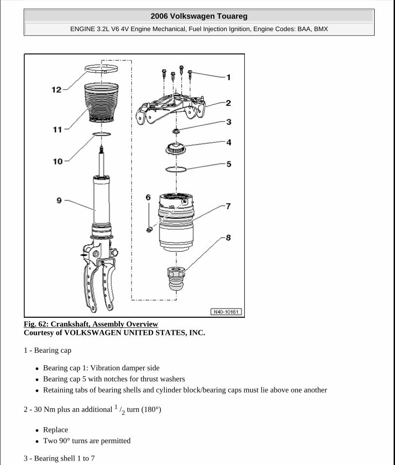
Fig. 62: Crankshaft, Assembly Overview Courtesy of VOLKSWAGEN UNITED STATES, INC.
1 - Bearing cap
Bearing cap 1: Vibration damper side
Bearing cap 5 with notches for thrust washers
Retaining tabs of bearing shells and cylinder block/bearing caps must lie above one another
2 - 30 Nm plus an additional 1 /2 turn (180°)
Replace
Two 90° turns are permitted
3 - Bearing shell 1 to 7
2006 Volkswagen Touareg
ENGINE 3.2L V6 4V Engine Mechanical, Fuel Injection Ignition, Engine Codes: BAA, BMX
Microsoft
Sunday, September 20, 2009 9:14:16 AM Page 50 © 2005 Mitchell Repair Information Company, LLC.
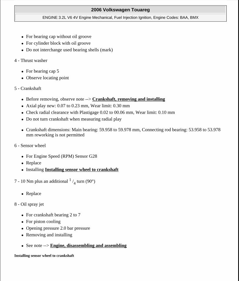
For bearing cap without oil groove
For cylinder block with oil groove
Do not interchange used bearing shells (mark)
4 - Thrust washer
For bearing cap 5
Observe locating point
5 - Crankshaft
Before removing, observe note --> Crankshaft, removing and installing
Axial play new: 0.07 to 0.23 mm, Wear limit: 0.30 mm
Check radial clearance with Plastigage 0.02 to 00.06 mm, Wear limit: 0.10 mm
Do not turn crankshaft when measuring radial play
Crankshaft dimensions: Main bearing: 59.958 to 59.978 mm, Connecting rod bearing: 53.958 to 53.978 mm reworking is not permitted
6 - Sensor wheel
For Engine Speed (RPM) Sensor G28
Replace
Installing Installing sensor wheel to crankshaft
7 - 10 Nm plus an additional 1 /4 turn (90°)
Replace
8 - Oil spray jet
For crankshaft bearing 2 to 7
For piston cooling
Opening pressure 2.0 bar pressure
Removing and installing
See note --> Engine, disassembling and assembling
Installing sensor wheel to crankshaft
2006 Volkswagen Touareg
ENGINE 3.2L V6 4V Engine Mechanical, Fuel Injection Ignition, Engine Codes: BAA, BMX
Microsoft
Sunday, September 20, 2009 9:14:16 AM Page 51 © 2005 Mitchell Repair Information Company, LLC.
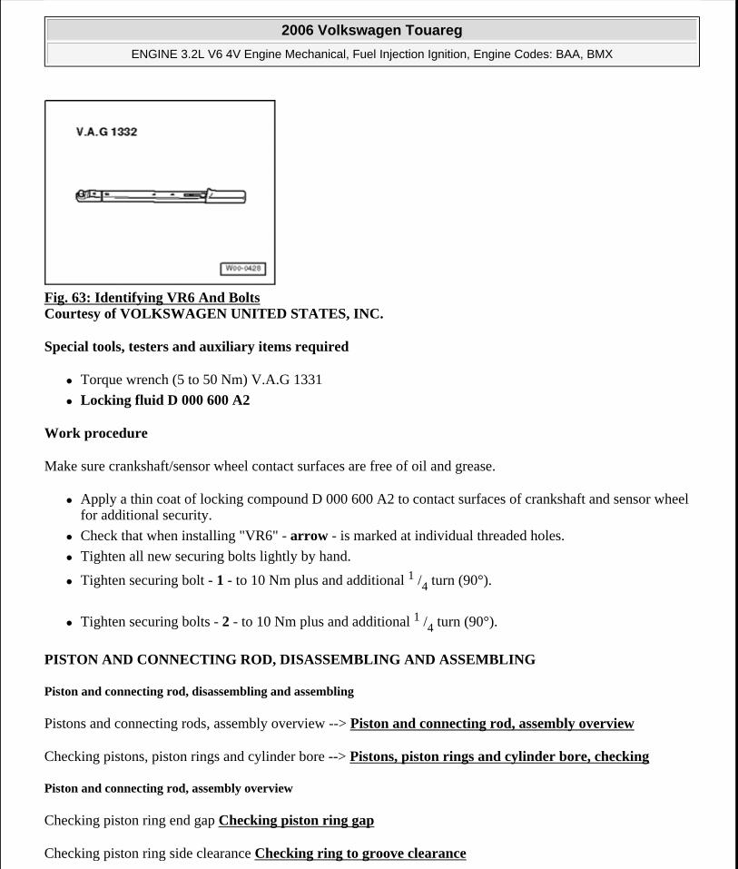
Fig. 63: Identifying VR6 And Bolts Courtesy of VOLKSWAGEN UNITED STATES, INC.
Special tools, testers and auxiliary items required
Torque wrench (5 to 50 Nm) V.A.G 1331
Locking fluid D 000 600 A2
Work procedure
Make sure crankshaft/sensor wheel contact surfaces are free of oil and grease.
Apply a thin coat of locking compound D 000 600 A2 to contact surfaces of crankshaft and sensor wheel for additional security.
Check that when installing "VR6" - arrow - is marked at individual threaded holes.
Tighten all new securing bolts lightly by hand.
Tighten securing bolt - 1 - to 10 Nm plus and additional 1 /4 turn (90°).
Tighten securing bolts - 2 - to 10 Nm plus and additional 1 /4 turn (90°).
PISTON AND CONNECTING ROD, DISASSEMBLING AND ASSEMBLING
Piston and connecting rod, disassembling and assembling
Pistons and connecting rods, assembly overview --> Piston and connecting rod, assembly overview
Checking pistons, piston rings and cylinder bore --> Pistons, piston rings and cylinder bore, checking
Piston and connecting rod, assembly overview
Checking piston ring end gap Checking piston ring gap
Checking piston ring side clearance Checking ring to groove clearance
2006 Volkswagen Touareg
ENGINE 3.2L V6 4V Engine Mechanical, Fuel Injection Ignition, Engine Codes: BAA, BMX
Microsoft
Sunday, September 20, 2009 9:14:16 AM Page 52 © 2005 Mitchell Repair Information Company, LLC.
Checking pistons Checking piston
Installing piston with Piston insertion Funnel T10147 Installing piston with under Installing piston with Piston insertion Funnel T10147
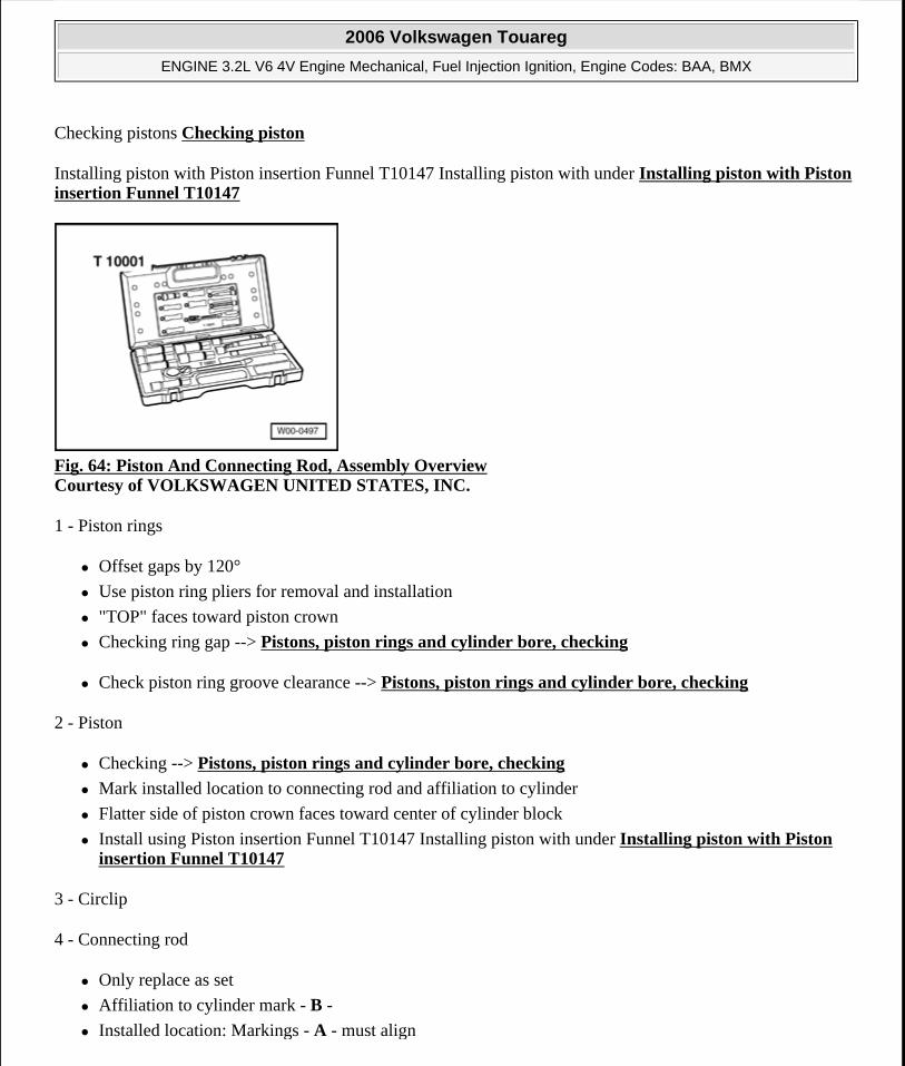
Fig. 64: Piston And Connecting Rod, Assembly Overview Courtesy of VOLKSWAGEN UNITED STATES, INC.
1 - Piston rings
Offset gaps by 120°
Use piston ring pliers for removal and installation
"TOP" faces toward piston crown
Checking ring gap --> Pistons, piston rings and cylinder bore, checking
Check piston ring groove clearance --> Pistons, piston rings and cylinder bore, checking
2 - Piston
Checking --> Pistons, piston rings and cylinder bore, checking
Mark installed location to connecting rod and affiliation to cylinder
Flatter side of piston crown faces toward center of cylinder block
Install using Piston insertion Funnel T10147 Installing piston with under Installing piston with Piston insertion Funnel T10147
3 - Circlip
4 - Connecting rod
Only replace as set
Affiliation to cylinder mark - B -
Installed location: Markings - A - must align
2006 Volkswagen Touareg
ENGINE 3.2L V6 4V Engine Mechanical, Fuel Injection Ignition, Engine Codes: BAA, BMX
Microsoft
Sunday, September 20, 2009 9:14:16 AM Page 53 © 2005 Mitchell Repair Information Company, LLC.
5 - Bearing shell
Note installation position
Do not interchange used bearing shells
Bearing shell retaining tabs must be firmly seated in notches
Axial play new: 0.05 to 00.31 mm, Wear limit: 0.40 mm
Measure radial clearance with Plastigage: New: 0.02 to 00.07 mm, Wear limit: 0.10 mm. Do not turn crankshaft when checking radial clearance
6 - Connecting rod bearing cap
Affiliation to cylinder mark - B -
Installed location: Markings - A - must align
7 - 30 Nm plus an additional 1 /4 turn (90°)
Replace
Lubricate threads and contact surface
Tighten to 30 Nm to measure radial play, do not turn further
8 - Cylinder block
Cylinder bore, checking --> Pistons, piston rings and cylinder bore, checking
Removing and installing crankshaft --> Crankshaft, removing and installing
Piston and cylinder dimensions --> Pistons, piston rings and cylinder bore, checking
9 - Piston pin
If difficult to move, heat piston to 6°C
Removing and installing using a Pilot Drift VW 222 A
Pistons, piston rings and cylinder bore, checking
Checking piston ring gap
2006 Volkswagen Touareg
ENGINE 3.2L V6 4V Engine Mechanical, Fuel Injection Ignition, Engine Codes: BAA, BMX
Microsoft
Sunday, September 20, 2009 9:14:16 AM Page 54 © 2005 Mitchell Repair Information Company, LLC.
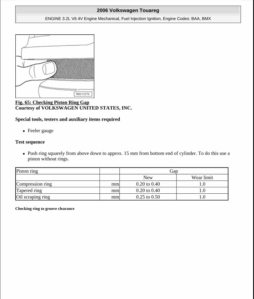
Fig. 65: Checking Piston Ring Gap Courtesy of VOLKSWAGEN UNITED STATES, INC.
Special tools, testers and auxiliary items required
Feeler gauge
Test sequence
Push ring squarely from above down to approx. 15 mm from bottom end of cylinder. To do this use a piston without rings.
Checking ring to groove clearance
Piston ring Gap New Wear limitCompression ring mm 0.20 to 0.40 1.0Tapered ring mm 0.20 to 0.40 1.0Oil scraping ring mm 0.25 to 0.50 1.0
2006 Volkswagen Touareg
ENGINE 3.2L V6 4V Engine Mechanical, Fuel Injection Ignition, Engine Codes: BAA, BMX
Microsoft
Sunday, September 20, 2009 9:14:16 AM Page 55 © 2005 Mitchell Repair Information Company, LLC.
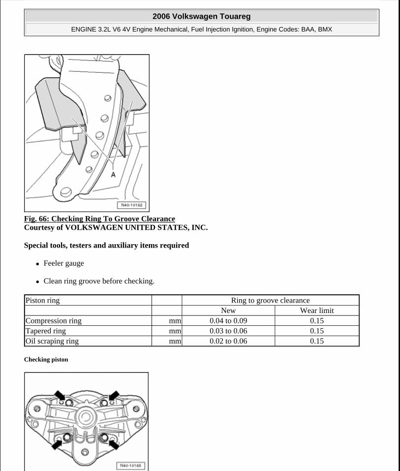
Fig. 66: Checking Ring To Groove Clearance Courtesy of VOLKSWAGEN UNITED STATES, INC.
Special tools, testers and auxiliary items required
Feeler gauge
Clean ring groove before checking.
Checking piston
Piston ring Ring to groove clearance New Wear limitCompression ring mm 0.04 to 0.09 0.15Tapered ring mm 0.03 to 0.06 0.15Oil scraping ring mm 0.02 to 0.06 0.15
2006 Volkswagen Touareg
ENGINE 3.2L V6 4V Engine Mechanical, Fuel Injection Ignition, Engine Codes: BAA, BMX
Microsoft
Sunday, September 20, 2009 9:14:16 AM Page 56 © 2005 Mitchell Repair Information Company, LLC.
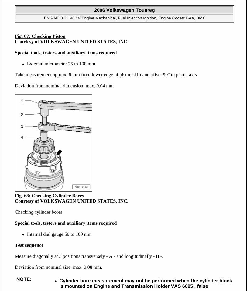
Fig. 67: Checking Piston Courtesy of VOLKSWAGEN UNITED STATES, INC.
Special tools, testers and auxiliary items required
External micrometer 75 to 100 mm
Take measurement approx. 6 mm from lower edge of piston skirt and offset 90° to piston axis.
Deviation from nominal dimension: max. 0.04 mm
Fig. 68: Checking Cylinder Bores Courtesy of VOLKSWAGEN UNITED STATES, INC.
Checking cylinder bores
Special tools, testers and auxiliary items required
Internal dial gauge 50 to 100 mm
Test sequence
Measure diagonally at 3 positions transversely - A - and longitudinally - B -.
Deviation from nominal size: max. 0.08 mm.
NOTE: Cylinder bore measurement may not be performed when the cylinder block is mounted on Engine and Transmission Holder VAS 6095 , false
2006 Volkswagen Touareg
ENGINE 3.2L V6 4V Engine Mechanical, Fuel Injection Ignition, Engine Codes: BAA, BMX
Microsoft
Sunday, September 20, 2009 9:14:16 AM Page 57 © 2005 Mitchell Repair Information Company, LLC.
Piston and cylinder dimensions
Installing piston with Piston insertion Funnel T10147
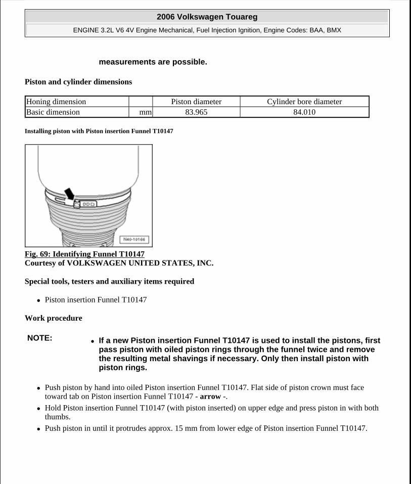
Fig. 69: Identifying Funnel T10147 Courtesy of VOLKSWAGEN UNITED STATES, INC.
Special tools, testers and auxiliary items required
Piston insertion Funnel T10147
Work procedure
Push piston by hand into oiled Piston insertion Funnel T10147. Flat side of piston crown must face toward tab on Piston insertion Funnel T10147 - arrow -.
Hold Piston insertion Funnel T10147 (with piston inserted) on upper edge and press piston in with both thumbs.
Push piston in until it protrudes approx. 15 mm from lower edge of Piston insertion Funnel T10147.
measurements are possible.
Honing dimension Piston diameter Cylinder bore diameterBasic dimension mm 83.965 84.010
NOTE: If a new Piston insertion Funnel T10147 is used to install the pistons, first pass piston with oiled piston rings through the funnel twice and remove the resulting metal shavings if necessary. Only then install piston with piston rings.
2006 Volkswagen Touareg
ENGINE 3.2L V6 4V Engine Mechanical, Fuel Injection Ignition, Engine Codes: BAA, BMX
Microsoft
Sunday, September 20, 2009 9:14:16 AM Page 58 © 2005 Mitchell Repair Information Company, LLC.
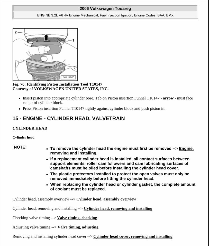
Fig. 70: Identifying Piston Installation Tool T10147 Courtesy of VOLKSWAGEN UNITED STATES, INC.
Insert piston into appropriate cylinder bore. Tab on Piston insertion Funnel T10147 - arrow - must face center of cylinder block.
Press Piston insertion Funnel T10147 tightly against cylinder block and push piston in.
15 - ENGINE - CYLINDER HEAD, VALVETRAIN
CYLINDER HEAD
Cylinder head
Cylinder head, assembly overview --> Cylinder head, assembly overview
Cylinder head, removing and installing --> Cylinder head, removing and installing
Checking valve timing --> Valve timing, checking
Adjusting valve timing --> Valve timing, adjusting
Removing and installing cylinder head cover --> Cylinder head cover, removing and installing
NOTE: To remove the cylinder head the engine must first be removed --> Engine, removing and installing.
If a replacement cylinder head is installed, all contact surfaces between support elements, roller cam followers and cam lubricating surfaces of camshafts must be oiled before installing the cylinder head cover.
The plastic protectors installed to protect the open valves must only be removed immediately before fitting the cylinder head.
When replacing the cylinder head or cylinder gasket, the complete amount of coolant must be replaced.
2006 Volkswagen Touareg
ENGINE 3.2L V6 4V Engine Mechanical, Fuel Injection Ignition, Engine Codes: BAA, BMX
Microsoft
Sunday, September 20, 2009 9:14:16 AM Page 59 © 2005 Mitchell Repair Information Company, LLC.
Cover, removing and installing --> Cover, removing and installing, assembly overview
Compression, checking --> Compression pressures, checking.
Valvetrain, servicing --> Valvetrain
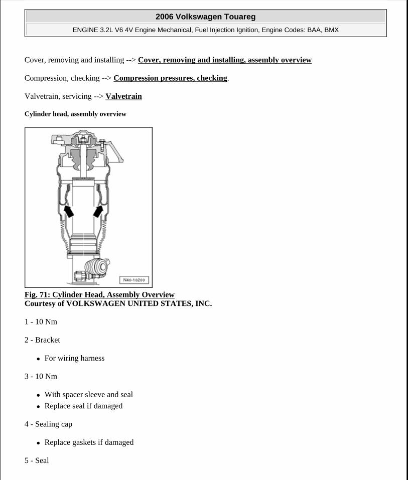
Cylinder head, assembly overview
Fig. 71: Cylinder Head, Assembly Overview Courtesy of VOLKSWAGEN UNITED STATES, INC.
1 - 10 Nm
2 - Bracket
For wiring harness
3 - 10 Nm
With spacer sleeve and seal
Replace seal if damaged
4 - Sealing cap
Replace gaskets if damaged
5 - Seal
2006 Volkswagen Touareg
ENGINE 3.2L V6 4V Engine Mechanical, Fuel Injection Ignition, Engine Codes: BAA, BMX
Microsoft
Sunday, September 20, 2009 9:14:16 AM Page 60 © 2005 Mitchell Repair Information Company, LLC.
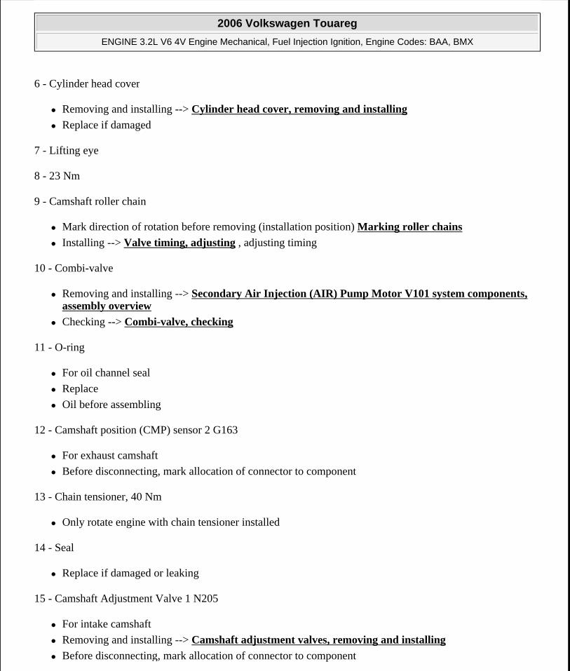
6 - Cylinder head cover
Removing and installing --> Cylinder head cover, removing and installing
Replace if damaged
7 - Lifting eye
8 - 23 Nm
9 - Camshaft roller chain
Mark direction of rotation before removing (installation position) Marking roller chains
Installing --> Valve timing, adjusting , adjusting timing
10 - Combi-valve
Removing and installing --> Secondary Air Injection (AIR) Pump Motor V101 system components, assembly overview
Checking --> Combi-valve, checking
11 - O-ring
For oil channel seal
Replace
Oil before assembling
12 - Camshaft position (CMP) sensor 2 G163
For exhaust camshaft
Before disconnecting, mark allocation of connector to component
13 - Chain tensioner, 40 Nm
Only rotate engine with chain tensioner installed
14 - Seal
Replace if damaged or leaking
15 - Camshaft Adjustment Valve 1 N205
For intake camshaft
Removing and installing --> Camshaft adjustment valves, removing and installing
Before disconnecting, mark allocation of connector to component
2006 Volkswagen Touareg
ENGINE 3.2L V6 4V Engine Mechanical, Fuel Injection Ignition, Engine Codes: BAA, BMX
Microsoft
Sunday, September 20, 2009 9:14:16 AM Page 61 © 2005 Mitchell Repair Information Company, LLC.
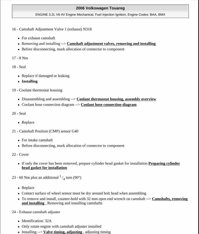
16 - Camshaft Adjustment Valve 1 (exhaust) N318
For exhaust camshaft
Removing and installing --> Camshaft adjustment valves, removing and installing
Before disconnecting, mark allocation of connector to component
17 - 8 Nm
18 - Seal
Replace if damaged or leaking
Installing
19 - Coolant thermostat housing
Disassembling and assembling --> Coolant thermostat housing, assembly overview
Coolant hose connection diagram --> Coolant hose connection diagram
20 - Seal
Replace
21 - Camshaft Position (CMP) sensor G40
For intake camshaft
Before disconnecting, mark allocation of connector to component
22 - Cover
If only the cover has been removed, prepare cylinder head gasket for installation Preparing cylinder head gasket for installation
23 - 60 Nm plus an additional 1 /4 turn (90°)
Replace
Contact surface of wheel sensor must be dry around bolt head when assembling
To remove and install, counter-hold with 32 mm open end wrench on camshaft --> Camshafts, removing and installing , Removing and installing camshafts
24 - Exhaust camshaft adjuster
Identification: 32A
Only rotate engine with camshaft adjuster installed
Installing --> Valve timing, adjusting , adjusting timing
2006 Volkswagen Touareg
ENGINE 3.2L V6 4V Engine Mechanical, Fuel Injection Ignition, Engine Codes: BAA, BMX
Microsoft
Sunday, September 20, 2009 9:14:16 AM Page 62 © 2005 Mitchell Repair Information Company, LLC.
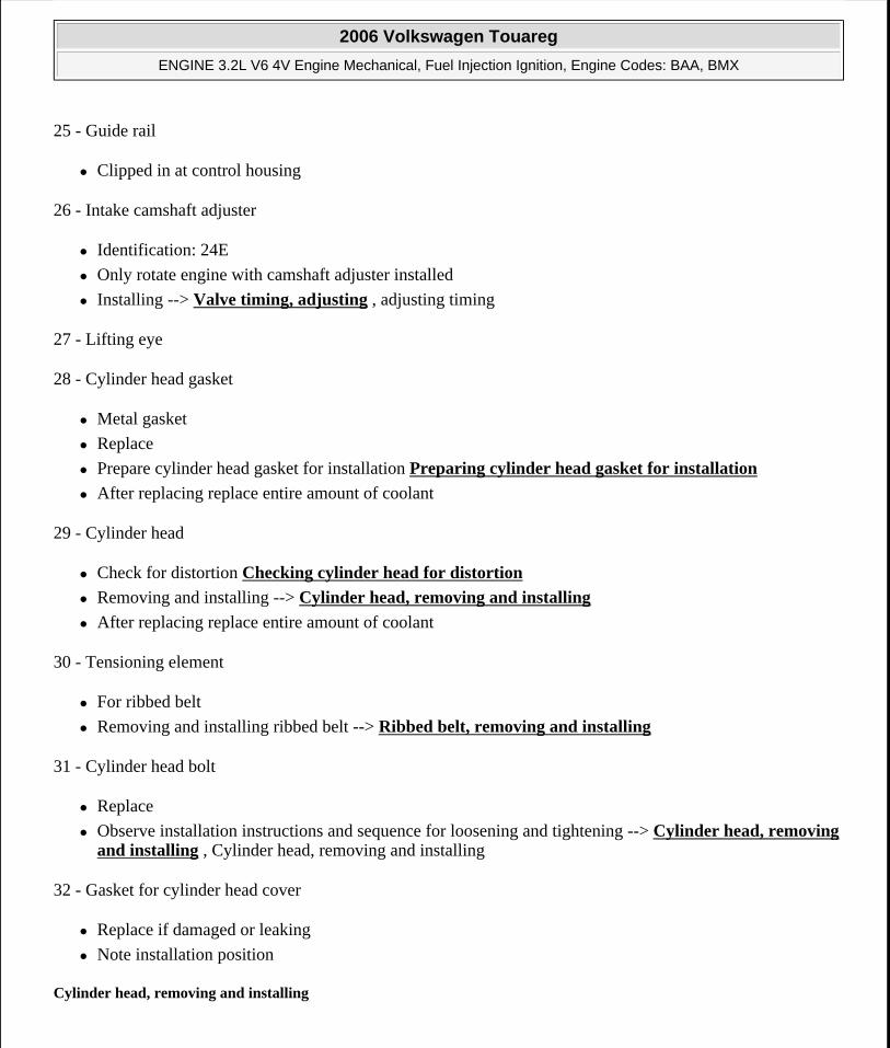
25 - Guide rail
Clipped in at control housing
26 - Intake camshaft adjuster
Identification: 24E
Only rotate engine with camshaft adjuster installed
Installing --> Valve timing, adjusting , adjusting timing
27 - Lifting eye
28 - Cylinder head gasket
Metal gasket
Replace
Prepare cylinder head gasket for installation Preparing cylinder head gasket for installation
After replacing replace entire amount of coolant
29 - Cylinder head
Check for distortion Checking cylinder head for distortion
Removing and installing --> Cylinder head, removing and installing
After replacing replace entire amount of coolant
30 - Tensioning element
For ribbed belt
Removing and installing ribbed belt --> Ribbed belt, removing and installing
31 - Cylinder head bolt
Replace
Observe installation instructions and sequence for loosening and tightening --> Cylinder head, removing and installing , Cylinder head, removing and installing
32 - Gasket for cylinder head cover
Replace if damaged or leaking
Note installation position
Cylinder head, removing and installing
2006 Volkswagen Touareg
ENGINE 3.2L V6 4V Engine Mechanical, Fuel Injection Ignition, Engine Codes: BAA, BMX
Microsoft
Sunday, September 20, 2009 9:14:16 AM Page 63 © 2005 Mitchell Repair Information Company, LLC.
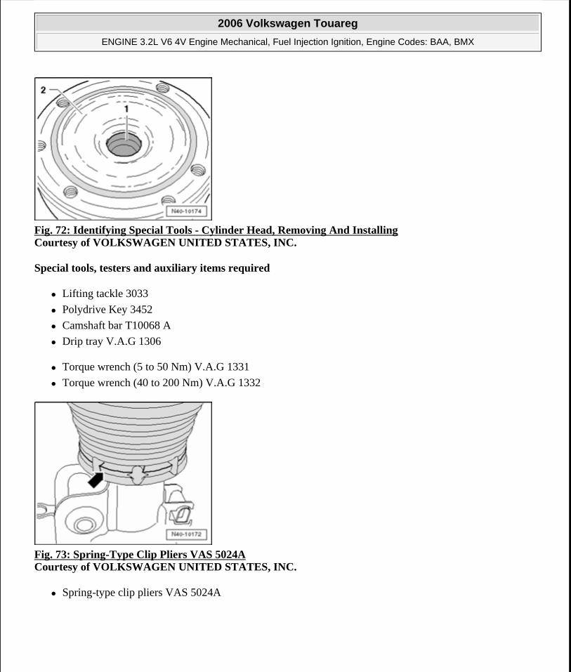
Fig. 72: Identifying Special Tools - Cylinder Head, Removing And Installing Courtesy of VOLKSWAGEN UNITED STATES, INC.
Special tools, testers and auxiliary items required
Lifting tackle 3033
Polydrive Key 3452
Camshaft bar T10068 A
Drip tray V.A.G 1306
Torque wrench (5 to 50 Nm) V.A.G 1331
Torque wrench (40 to 200 Nm) V.A.G 1332
Fig. 73: Spring-Type Clip Pliers VAS 5024A Courtesy of VOLKSWAGEN UNITED STATES, INC.
Spring-type clip pliers VAS 5024A
2006 Volkswagen Touareg
ENGINE 3.2L V6 4V Engine Mechanical, Fuel Injection Ignition, Engine Codes: BAA, BMX
Microsoft
Sunday, September 20, 2009 9:14:16 AM Page 64 © 2005 Mitchell Repair Information Company, LLC.
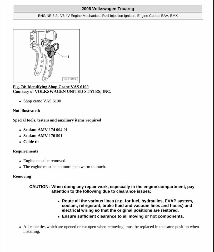
Fig. 74: Identifying Shop Crane VAS 6100 Courtesy of VOLKSWAGEN UNITED STATES, INC.
Shop crane VAS 6100
Not illustrated:
Special tools, testers and auxiliary items required
Sealant AMV 174 004 01
Sealant AMV 176 501
Cable tie
Requirements
Engine must be removed.
The engine must be no more than warm to touch.
Removing
All cable ties which are opened or cut open when removing, must be replaced in the same position when installing.
CAUTION: When doing any repair work, especially in the engine compartment, pay attention to the following due to clearance issues:
Route all the various lines (e.g. for fuel, hydraulics, EVAP system, coolant, refrigerant, brake fluid and vacuum lines and hoses) and electrical wiring so that the original positions are restored.
Ensure sufficient clearance to all moving or hot components.
2006 Volkswagen Touareg
ENGINE 3.2L V6 4V Engine Mechanical, Fuel Injection Ignition, Engine Codes: BAA, BMX
Microsoft
Sunday, September 20, 2009 9:14:16 AM Page 65 © 2005 Mitchell Repair Information Company, LLC.
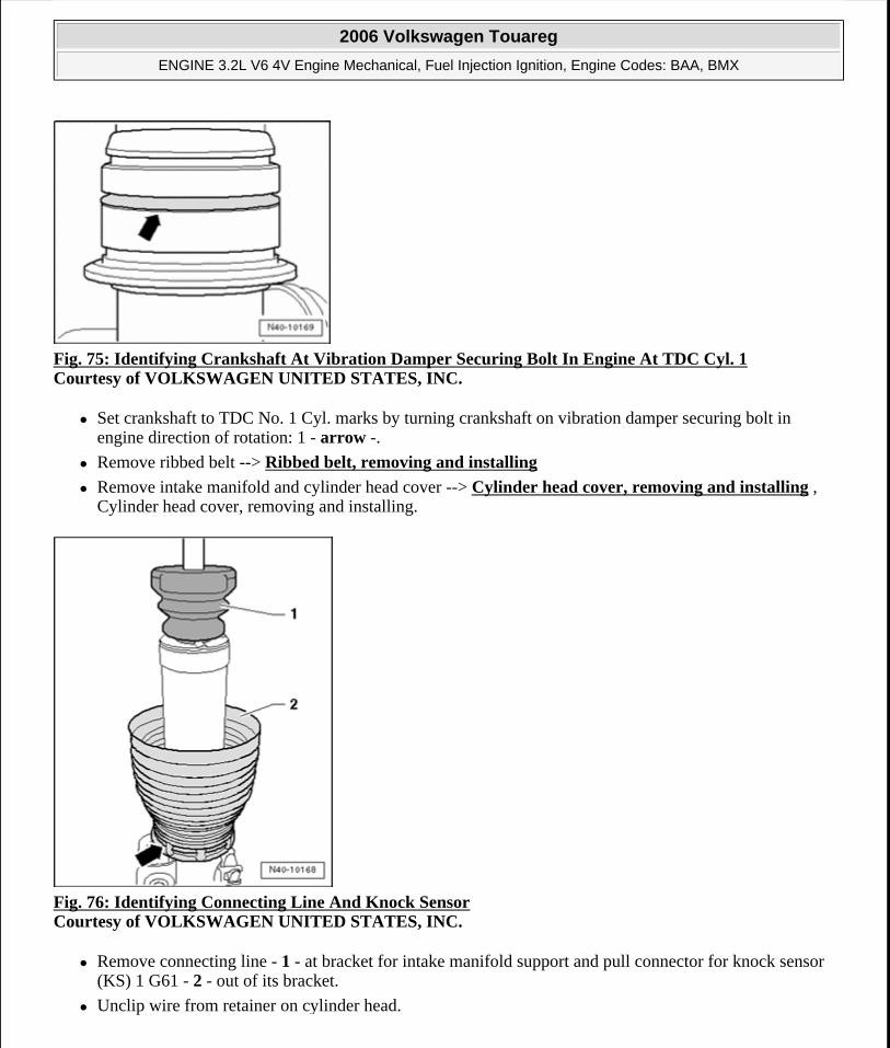
Fig. 75: Identifying Crankshaft At Vibration Damper Securing Bolt In Engine At TDC Cyl. 1 Courtesy of VOLKSWAGEN UNITED STATES, INC.
Set crankshaft to TDC No. 1 Cyl. marks by turning crankshaft on vibration damper securing bolt in engine direction of rotation: 1 - arrow -.
Remove ribbed belt --> Ribbed belt, removing and installing
Remove intake manifold and cylinder head cover --> Cylinder head cover, removing and installing , Cylinder head cover, removing and installing.
Fig. 76: Identifying Connecting Line And Knock Sensor Courtesy of VOLKSWAGEN UNITED STATES, INC.
Remove connecting line - 1 - at bracket for intake manifold support and pull connector for knock sensor (KS) 1 G61 - 2 - out of its bracket.
Unclip wire from retainer on cylinder head.
2006 Volkswagen Touareg
ENGINE 3.2L V6 4V Engine Mechanical, Fuel Injection Ignition, Engine Codes: BAA, BMX
Microsoft
Sunday, September 20, 2009 9:14:16 AM Page 66 © 2005 Mitchell Repair Information Company, LLC.
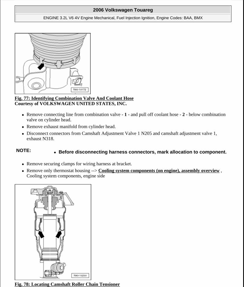
Fig. 77: Identifying Combination Valve And Coolant Hose Courtesy of VOLKSWAGEN UNITED STATES, INC.
Remove connecting line from combination valve - 1 - and pull off coolant hose - 2 - below combination valve on cylinder head.
Remove exhaust manifold from cylinder head.
Disconnect connectors from Camshaft Adjustment Valve 1 N205 and camshaft adjustment valve 1, exhaust N318.
Remove securing clamps for wiring harness at bracket.
Remove only thermostat housing --> Cooling system components (on engine), assembly overview , Cooling system components, engine side
Fig. 78: Locating Camshaft Roller Chain Tensioner
NOTE: Before disconnecting harness connectors, mark allocation to component.
2006 Volkswagen Touareg
ENGINE 3.2L V6 4V Engine Mechanical, Fuel Injection Ignition, Engine Codes: BAA, BMX
Microsoft
Sunday, September 20, 2009 9:14:16 AM Page 67 © 2005 Mitchell Repair Information Company, LLC.
Courtesy of VOLKSWAGEN UNITED STATES, INC.
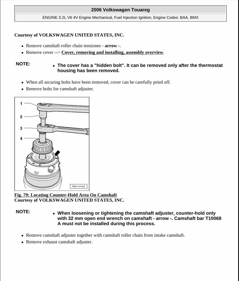
Remove camshaft roller chain tensioner - arrow -.
Remove cover --> Cover, removing and installing, assembly overview.
When all securing bolts have been removed, cover can be carefully pried off.
Remove bolts for camshaft adjuster.
Fig. 79: Locating Counter-Hold Area On Camshaft Courtesy of VOLKSWAGEN UNITED STATES, INC.
Remove camshaft adjuster together with camshaft roller chain from intake camshaft.
Remove exhaust camshaft adjuster.
NOTE: The cover has a "hidden bolt". It can be removed only after the thermostat housing has been removed.
NOTE: When loosening or tightening the camshaft adjuster, counter-hold only with 32 mm open end wrench on camshaft - arrow -. Camshaft bar T10068 A must not be installed during this process.
2006 Volkswagen Touareg
ENGINE 3.2L V6 4V Engine Mechanical, Fuel Injection Ignition, Engine Codes: BAA, BMX
Microsoft
Sunday, September 20, 2009 9:14:16 AM Page 68 © 2005 Mitchell Repair Information Company, LLC.
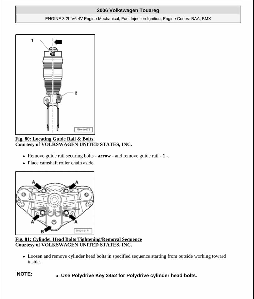
Fig. 80: Locating Guide Rail & Bolts Courtesy of VOLKSWAGEN UNITED STATES, INC.
Remove guide rail securing bolts - arrow - and remove guide rail - 1 -.
Place camshaft roller chain aside.
Fig. 81: Cylinder Head Bolts Tightening/Removal Sequence Courtesy of VOLKSWAGEN UNITED STATES, INC.
Loosen and remove cylinder head bolts in specified sequence starting from outside working toward inside.
NOTE: Use Polydrive Key 3452 for Polydrive cylinder head bolts.
2006 Volkswagen Touareg
ENGINE 3.2L V6 4V Engine Mechanical, Fuel Injection Ignition, Engine Codes: BAA, BMX
Microsoft
Sunday, September 20, 2009 9:14:16 AM Page 69 © 2005 Mitchell Repair Information Company, LLC.
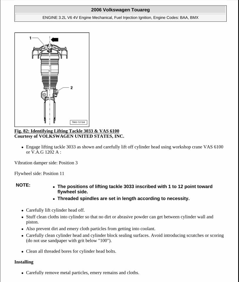
Fig. 82: Identifying Lifting Tackle 3033 & VAS 6100 Courtesy of VOLKSWAGEN UNITED STATES, INC.
Engage lifting tackle 3033 as shown and carefully lift off cylinder head using workshop crane VAS 6100 or V.A.G 1202 A :
Vibration damper side: Position 3
Flywheel side: Position 11
Carefully lift cylinder head off.
Stuff clean cloths into cylinder so that no dirt or abrasive powder can get between cylinder wall and piston.
Also prevent dirt and emery cloth particles from getting into coolant.
Carefully clean cylinder head and cylinder block sealing surfaces. Avoid introducing scratches or scoring (do not use sandpaper with grit below "100").
Clean all threaded bores for cylinder head bolts.
Installing
Carefully remove metal particles, emery remains and cloths.
NOTE: The positions of lifting tackle 3033 inscribed with 1 to 12 point toward flywheel side.
Threaded spindles are set in length according to necessity.
2006 Volkswagen Touareg
ENGINE 3.2L V6 4V Engine Mechanical, Fuel Injection Ignition, Engine Codes: BAA, BMX
Microsoft
Sunday, September 20, 2009 9:14:16 AM Page 70 © 2005 Mitchell Repair Information Company, LLC.
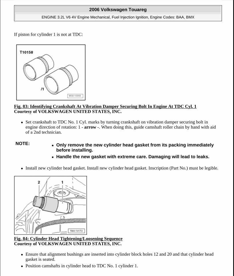
If piston for cylinder 1 is not at TDC:
Fig. 83: Identifying Crankshaft At Vibration Damper Securing Bolt In Engine At TDC Cyl. 1 Courtesy of VOLKSWAGEN UNITED STATES, INC.
Set crankshaft to TDC No. 1 Cyl. marks by turning crankshaft on vibration damper securing bolt in engine direction of rotation: 1 - arrow -. When doing this, guide camshaft roller chain by hand with aid of a 2nd technician.
Install new cylinder head gasket. Install new cylinder head gasket. Inscription (Part No.) must be legible.
Fig. 84: Cylinder Head Tightening/Loosening Sequence Courtesy of VOLKSWAGEN UNITED STATES, INC.
Ensure that alignment bushings are inserted into cylinder block holes 12 and 20 and that cylinder head gasket is seated.
Position camshafts in cylinder head to TDC No. 1 cylinder 1.
NOTE: Only remove the new cylinder head gasket from its packing immediately before installing.
Handle the new gasket with extreme care. Damaging will lead to leaks.
2006 Volkswagen Touareg
ENGINE 3.2L V6 4V Engine Mechanical, Fuel Injection Ignition, Engine Codes: BAA, BMX
Microsoft
Sunday, September 20, 2009 9:14:16 AM Page 71 © 2005 Mitchell Repair Information Company, LLC.
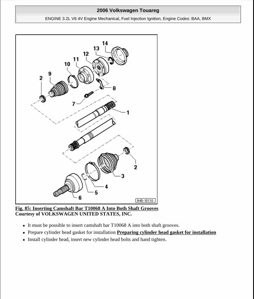
Fig. 85: Inserting Camshaft Bar T10068 A Into Both Shaft Grooves Courtesy of VOLKSWAGEN UNITED STATES, INC.
It must be possible to insert camshaft bar T10068 A into both shaft grooves.
Prepare cylinder head gasket for installation Preparing cylinder head gasket for installation
Install cylinder head, insert new cylinder head bolts and hand tighten.
2006 Volkswagen Touareg
ENGINE 3.2L V6 4V Engine Mechanical, Fuel Injection Ignition, Engine Codes: BAA, BMX
Microsoft
Sunday, September 20, 2009 9:14:17 AM Page 72 © 2005 Mitchell Repair Information Company, LLC.
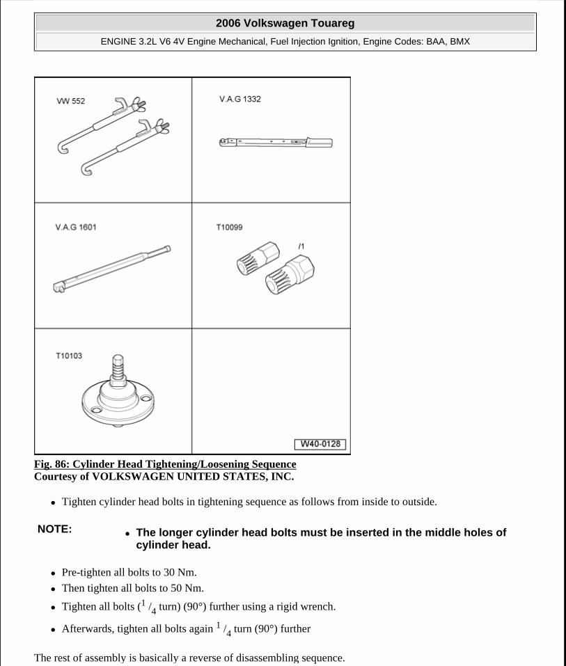
Fig. 86: Cylinder Head Tightening/Loosening Sequence Courtesy of VOLKSWAGEN UNITED STATES, INC.
Tighten cylinder head bolts in tightening sequence as follows from inside to outside.
Pre-tighten all bolts to 30 Nm.
Then tighten all bolts to 50 Nm.
Tighten all bolts (1 /4 turn) (90°) further using a rigid wrench.
Afterwards, tighten all bolts again 1 /4 turn (90°) further
The rest of assembly is basically a reverse of disassembling sequence.
NOTE: The longer cylinder head bolts must be inserted in the middle holes of cylinder head.
2006 Volkswagen Touareg
ENGINE 3.2L V6 4V Engine Mechanical, Fuel Injection Ignition, Engine Codes: BAA, BMX
Microsoft
Sunday, September 20, 2009 9:14:17 AM Page 73 © 2005 Mitchell Repair Information Company, LLC.
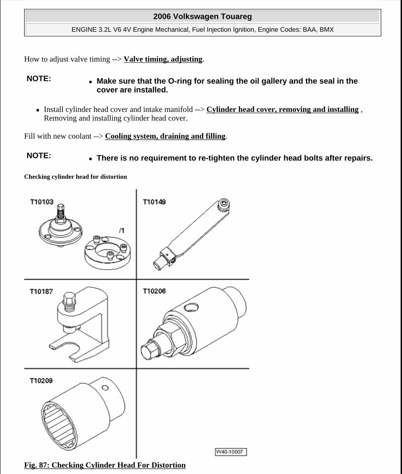
How to adjust valve timing --> Valve timing, adjusting.
Install cylinder head cover and intake manifold --> Cylinder head cover, removing and installing , Removing and installing cylinder head cover.
Fill with new coolant --> Cooling system, draining and filling.
Checking cylinder head for distortion
Fig. 87: Checking Cylinder Head For Distortion
NOTE: Make sure that the O-ring for sealing the oil gallery and the seal in the cover are installed.
NOTE: There is no requirement to re-tighten the cylinder head bolts after repairs.
2006 Volkswagen Touareg
ENGINE 3.2L V6 4V Engine Mechanical, Fuel Injection Ignition, Engine Codes: BAA, BMX
Microsoft
Sunday, September 20, 2009 9:14:17 AM Page 74 © 2005 Mitchell Repair Information Company, LLC.
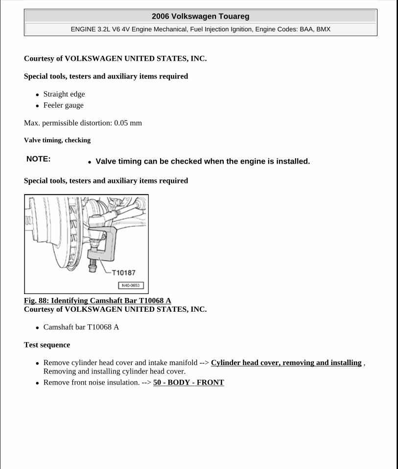
Courtesy of VOLKSWAGEN UNITED STATES, INC.
Special tools, testers and auxiliary items required
Straight edge
Feeler gauge
Max. permissible distortion: 0.05 mm
Valve timing, checking
Special tools, testers and auxiliary items required
Fig. 88: Identifying Camshaft Bar T10068 A Courtesy of VOLKSWAGEN UNITED STATES, INC.
Camshaft bar T10068 A
Test sequence
Remove cylinder head cover and intake manifold --> Cylinder head cover, removing and installing , Removing and installing cylinder head cover.
Remove front noise insulation. --> 50 - BODY - FRONT
NOTE: Valve timing can be checked when the engine is installed.
2006 Volkswagen Touareg
ENGINE 3.2L V6 4V Engine Mechanical, Fuel Injection Ignition, Engine Codes: BAA, BMX
Microsoft
Sunday, September 20, 2009 9:14:17 AM Page 75 © 2005 Mitchell Repair Information Company, LLC.
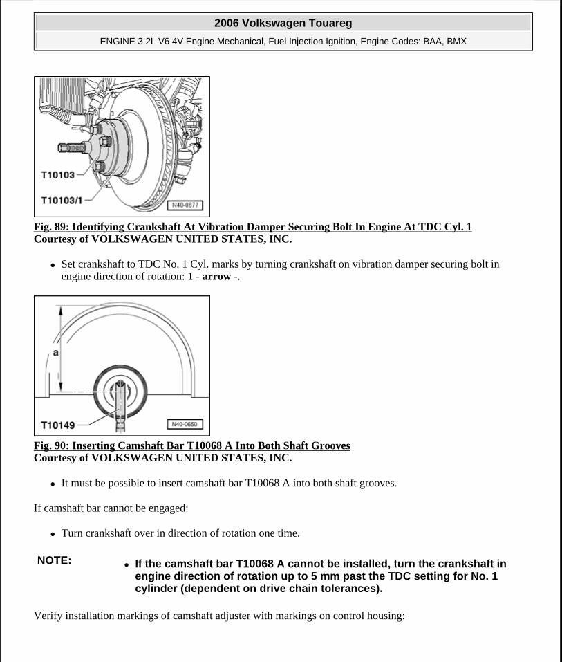
Fig. 89: Identifying Crankshaft At Vibration Damper Securing Bolt In Engine At TDC Cyl. 1 Courtesy of VOLKSWAGEN UNITED STATES, INC.
Set crankshaft to TDC No. 1 Cyl. marks by turning crankshaft on vibration damper securing bolt in engine direction of rotation: 1 - arrow -.
Fig. 90: Inserting Camshaft Bar T10068 A Into Both Shaft Grooves Courtesy of VOLKSWAGEN UNITED STATES, INC.
It must be possible to insert camshaft bar T10068 A into both shaft grooves.
If camshaft bar cannot be engaged:
Turn crankshaft over in direction of rotation one time.
Verify installation markings of camshaft adjuster with markings on control housing:
NOTE: If the camshaft bar T10068 A cannot be installed, turn the crankshaft in engine direction of rotation up to 5 mm past the TDC setting for No. 1 cylinder (dependent on drive chain tolerances).
2006 Volkswagen Touareg
ENGINE 3.2L V6 4V Engine Mechanical, Fuel Injection Ignition, Engine Codes: BAA, BMX
Microsoft
Sunday, September 20, 2009 9:14:17 AM Page 76 © 2005 Mitchell Repair Information Company, LLC.
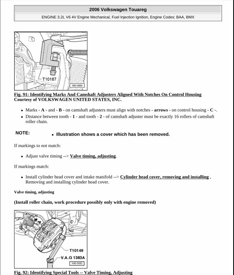
Fig. 91: Identifying Marks And Camshaft Adjusters Aligned With Notches On Control Housing Courtesy of VOLKSWAGEN UNITED STATES, INC.
Marks - A - and - B - on camshaft adjusters must align with notches - arrows - on control housing - C -.
Distance between tooth - 1 - and tooth - 2 - of camshaft adjuster must be exactly 16 rollers of camshaft roller chain.
If markings to not match:
Adjust valve timing --> Valve timing, adjusting.
If markings match:
Install cylinder head cover and intake manifold --> Cylinder head cover, removing and installing , Removing and installing cylinder head cover.
Valve timing, adjusting
(Install roller chain, work procedure possibly only with engine removed)
Fig. 92: Identifying Special Tools -- Valve Timing, Adjusting
NOTE: Illustration shows a cover which has been removed.
2006 Volkswagen Touareg
ENGINE 3.2L V6 4V Engine Mechanical, Fuel Injection Ignition, Engine Codes: BAA, BMX
Microsoft
Sunday, September 20, 2009 9:14:17 AM Page 77 © 2005 Mitchell Repair Information Company, LLC.
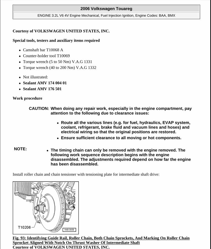
Courtesy of VOLKSWAGEN UNITED STATES, INC.
Special tools, testers and auxiliary items required
Camshaft bar T10068 A
Counter-holder tool T10069
Torque wrench (5 to 50 Nm) V.A.G 1331
Torque wrench (40 to 200 Nm) V.A.G 1332
Not illustrated:
Sealant AMV 174 004 01
Sealant AMV 176 501
Work procedure
Install roller chain and chain tensioner with tensioning plate for intermediate shaft drive:
Fig. 93: Identifying Guide Rail, Roller Chain, Both Chain Sprockets, And Marking On Roller Chain Sprocket Aligned With Notch On Thrust Washer Of Intermediate Shaft Courtesy of VOLKSWAGEN UNITED STATES, INC.
CAUTION: When doing any repair work, especially in the engine compartment, pay attention to the following due to clearance issues:
Route all the various lines (e.g. for fuel, hydraulics, EVAP system, coolant, refrigerant, brake fluid and vacuum lines and hoses) and electrical wiring so that the original positions are restored.
Ensure sufficient clearance to all moving or hot components.
NOTE: The timing chain can only be removed with the engine removed. The following work sequence description begins with the engine disassembled. The adjustments required depend on how far the engine has been disassembled.
2006 Volkswagen Touareg
ENGINE 3.2L V6 4V Engine Mechanical, Fuel Injection Ignition, Engine Codes: BAA, BMX
Microsoft
Sunday, September 20, 2009 9:14:17 AM Page 78 © 2005 Mitchell Repair Information Company, LLC.
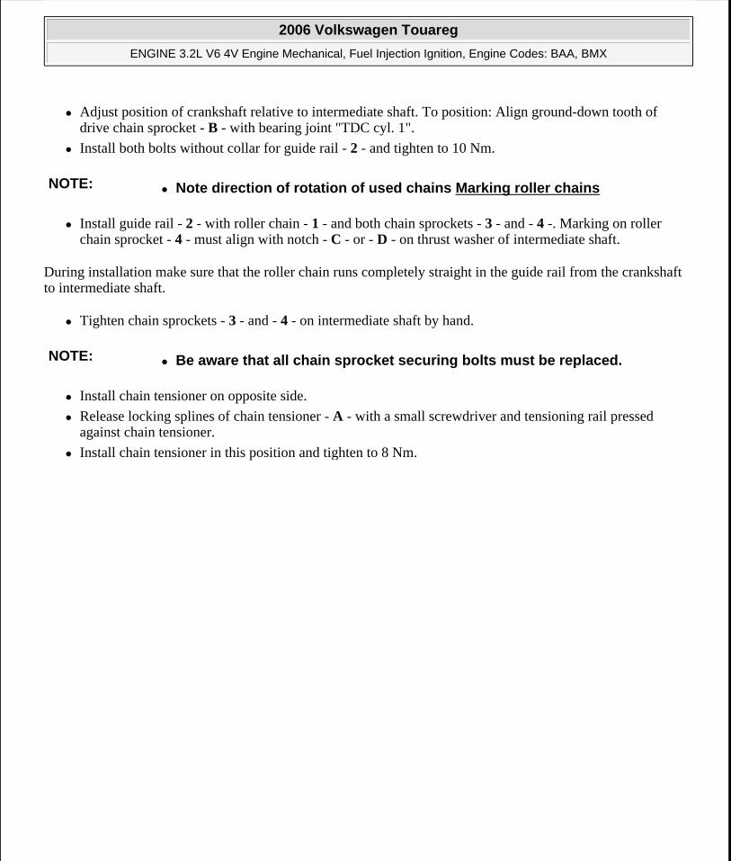
Adjust position of crankshaft relative to intermediate shaft. To position: Align ground-down tooth of drive chain sprocket - B - with bearing joint "TDC cyl. 1".
Install both bolts without collar for guide rail - 2 - and tighten to 10 Nm.
Install guide rail - 2 - with roller chain - 1 - and both chain sprockets - 3 - and - 4 -. Marking on roller chain sprocket - 4 - must align with notch - C - or - D - on thrust washer of intermediate shaft.
During installation make sure that the roller chain runs completely straight in the guide rail from the crankshaft to intermediate shaft.
Tighten chain sprockets - 3 - and - 4 - on intermediate shaft by hand.
Install chain tensioner on opposite side.
Release locking splines of chain tensioner - A - with a small screwdriver and tensioning rail pressed against chain tensioner.
Install chain tensioner in this position and tighten to 8 Nm.
NOTE: Note direction of rotation of used chains Marking roller chains
NOTE: Be aware that all chain sprocket securing bolts must be replaced.
2006 Volkswagen Touareg
ENGINE 3.2L V6 4V Engine Mechanical, Fuel Injection Ignition, Engine Codes: BAA, BMX
Microsoft
Sunday, September 20, 2009 9:14:17 AM Page 79 © 2005 Mitchell Repair Information Company, LLC.
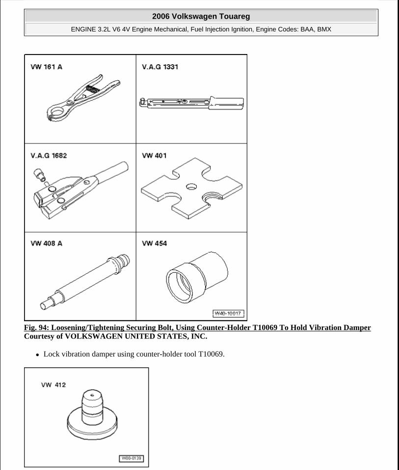
Fig. 94: Loosening/Tightening Securing Bolt, Using Counter-Holder T10069 To Hold Vibration DamperCourtesy of VOLKSWAGEN UNITED STATES, INC.
Lock vibration damper using counter-holder tool T10069.
2006 Volkswagen Touareg
ENGINE 3.2L V6 4V Engine Mechanical, Fuel Injection Ignition, Engine Codes: BAA, BMX
Microsoft
Sunday, September 20, 2009 9:14:17 AM Page 80 © 2005 Mitchell Repair Information Company, LLC.
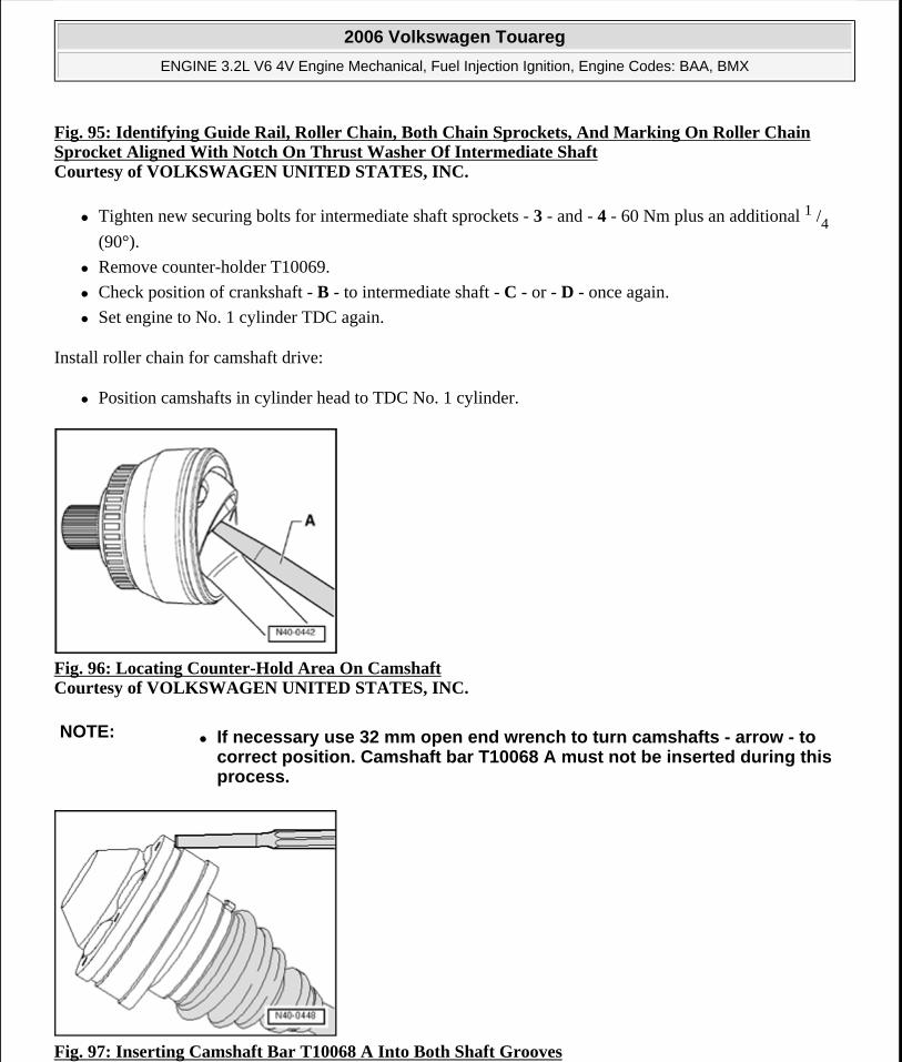
Fig. 95: Identifying Guide Rail, Roller Chain, Both Chain Sprockets, And Marking On Roller Chain Sprocket Aligned With Notch On Thrust Washer Of Intermediate Shaft Courtesy of VOLKSWAGEN UNITED STATES, INC.
Tighten new securing bolts for intermediate shaft sprockets - 3 - and - 4 - 60 Nm plus an additional 1 /4
(90°).
Remove counter-holder T10069.
Check position of crankshaft - B - to intermediate shaft - C - or - D - once again.
Set engine to No. 1 cylinder TDC again.
Install roller chain for camshaft drive:
Position camshafts in cylinder head to TDC No. 1 cylinder.
Fig. 96: Locating Counter-Hold Area On Camshaft Courtesy of VOLKSWAGEN UNITED STATES, INC.
Fig. 97: Inserting Camshaft Bar T10068 A Into Both Shaft Grooves
NOTE: If necessary use 32 mm open end wrench to turn camshafts - arrow - to correct position. Camshaft bar T10068 A must not be inserted during this process.
2006 Volkswagen Touareg
ENGINE 3.2L V6 4V Engine Mechanical, Fuel Injection Ignition, Engine Codes: BAA, BMX
Microsoft
Sunday, September 20, 2009 9:14:17 AM Page 81 © 2005 Mitchell Repair Information Company, LLC.
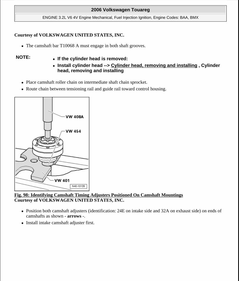
Courtesy of VOLKSWAGEN UNITED STATES, INC.
The camshaft bar T10068 A must engage in both shaft grooves.
Place camshaft roller chain on intermediate shaft chain sprocket.
Route chain between tensioning rail and guide rail toward control housing.
Fig. 98: Identifying Camshaft Timing Adjusters Positioned On Camshaft Mountings Courtesy of VOLKSWAGEN UNITED STATES, INC.
Position both camshaft adjusters (identification: 24E on intake side and 32A on exhaust side) on ends of camshafts as shown - arrows -.
Install intake camshaft adjuster first.
NOTE: If the cylinder head is removed:
Install cylinder head --> Cylinder head, removing and installing , Cylinder head, removing and installing
2006 Volkswagen Touareg
ENGINE 3.2L V6 4V Engine Mechanical, Fuel Injection Ignition, Engine Codes: BAA, BMX
Microsoft
Sunday, September 20, 2009 9:14:17 AM Page 82 © 2005 Mitchell Repair Information Company, LLC.
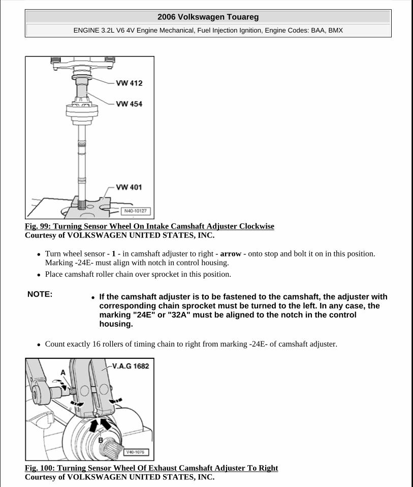
Fig. 99: Turning Sensor Wheel On Intake Camshaft Adjuster Clockwise Courtesy of VOLKSWAGEN UNITED STATES, INC.
Turn wheel sensor - 1 - in camshaft adjuster to right - arrow - onto stop and bolt it on in this position. Marking -24E- must align with notch in control housing.
Place camshaft roller chain over sprocket in this position.
Count exactly 16 rollers of timing chain to right from marking -24E- of camshaft adjuster.
Fig. 100: Turning Sensor Wheel Of Exhaust Camshaft Adjuster To Right Courtesy of VOLKSWAGEN UNITED STATES, INC.
NOTE: If the camshaft adjuster is to be fastened to the camshaft, the adjuster with corresponding chain sprocket must be turned to the left. In any case, the marking "24E" or "32A" must be aligned to the notch in the control housing.
2006 Volkswagen Touareg
ENGINE 3.2L V6 4V Engine Mechanical, Fuel Injection Ignition, Engine Codes: BAA, BMX
Microsoft
Sunday, September 20, 2009 9:14:17 AM Page 83 © 2005 Mitchell Repair Information Company, LLC.
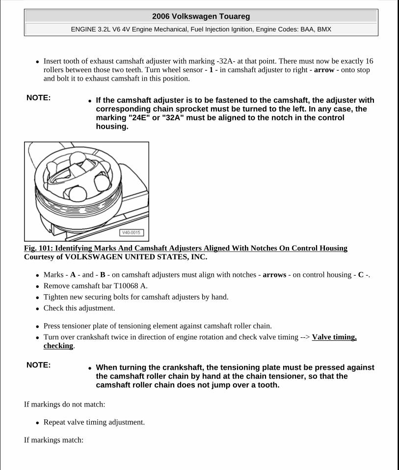
Insert tooth of exhaust camshaft adjuster with marking -32A- at that point. There must now be exactly 16 rollers between those two teeth. Turn wheel sensor - 1 - in camshaft adjuster to right - arrow - onto stop and bolt it to exhaust camshaft in this position.
Fig. 101: Identifying Marks And Camshaft Adjusters Aligned With Notches On Control Housing Courtesy of VOLKSWAGEN UNITED STATES, INC.
Marks - A - and - B - on camshaft adjusters must align with notches - arrows - on control housing - C -.
Remove camshaft bar T10068 A.
Tighten new securing bolts for camshaft adjusters by hand.
Check this adjustment.
Press tensioner plate of tensioning element against camshaft roller chain.
Turn over crankshaft twice in direction of engine rotation and check valve timing --> Valve timing, checking.
If markings do not match:
Repeat valve timing adjustment.
If markings match:
NOTE: If the camshaft adjuster is to be fastened to the camshaft, the adjuster with corresponding chain sprocket must be turned to the left. In any case, the marking "24E" or "32A" must be aligned to the notch in the control housing.
NOTE: When turning the crankshaft, the tensioning plate must be pressed against the camshaft roller chain by hand at the chain tensioner, so that the camshaft roller chain does not jump over a tooth.
2006 Volkswagen Touareg
ENGINE 3.2L V6 4V Engine Mechanical, Fuel Injection Ignition, Engine Codes: BAA, BMX
Microsoft
Sunday, September 20, 2009 9:14:17 AM Page 84 © 2005 Mitchell Repair Information Company, LLC.
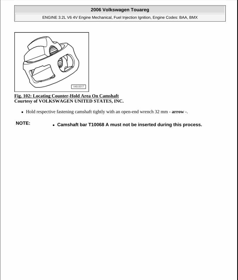
Fig. 102: Locating Counter-Hold Area On Camshaft Courtesy of VOLKSWAGEN UNITED STATES, INC.
Hold respective fastening camshaft tightly with an open-end wrench 32 mm - arrow -.
NOTE: Camshaft bar T10068 A must not be inserted during this process.
2006 Volkswagen Touareg
ENGINE 3.2L V6 4V Engine Mechanical, Fuel Injection Ignition, Engine Codes: BAA, BMX
Microsoft
Sunday, September 20, 2009 9:14:17 AM Page 85 © 2005 Mitchell Repair Information Company, LLC.
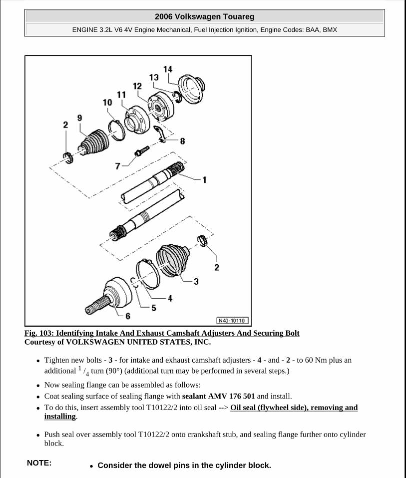
Fig. 103: Identifying Intake And Exhaust Camshaft Adjusters And Securing Bolt Courtesy of VOLKSWAGEN UNITED STATES, INC.
Tighten new bolts - 3 - for intake and exhaust camshaft adjusters - 4 - and - 2 - to 60 Nm plus an additional 1 /4 turn (90°) (additional turn may be performed in several steps.)
Now sealing flange can be assembled as follows:
Coat sealing surface of sealing flange with sealant AMV 176 501 and install.
To do this, insert assembly tool T10122/2 into oil seal --> Oil seal (flywheel side), removing and installing.
Push seal over assembly tool T10122/2 onto crankshaft stub, and sealing flange further onto cylinder block.
NOTE: Consider the dowel pins in the cylinder block.
2006 Volkswagen Touareg
ENGINE 3.2L V6 4V Engine Mechanical, Fuel Injection Ignition, Engine Codes: BAA, BMX
Microsoft
Sunday, September 20, 2009 9:14:17 AM Page 86 © 2005 Mitchell Repair Information Company, LLC.
Tighten bolts to 8 Nm.
Remove assembly tool T10122/2 from crankshaft stub.
Prepare cylinder head gasket for installation Preparing cylinder head gasket for installation
Lubricate O-ring for oil channel seal and install with oil seal into cover.
Install cover, insert all securing bolts with corresponding brackets and tighten lightly.
First fasten bolts M8 to 23 Nm, then fasten bolts M6 to 8 Nm.
Install chain tensioner for camshaft roller chain and tighten to 40 Nm.
Turn over crankshaft twice in direction of engine rotation and check valve timing again.
Bolt on thermostat housing.
Install cylinder head cover and intake manifold --> Cylinder head cover, removing and installing , Removing and installing cylinder head cover.
Cylinder head cover, removing and installing
2006 Volkswagen Touareg
ENGINE 3.2L V6 4V Engine Mechanical, Fuel Injection Ignition, Engine Codes: BAA, BMX
Microsoft
Sunday, September 20, 2009 9:14:17 AM Page 87 © 2005 Mitchell Repair Information Company, LLC.
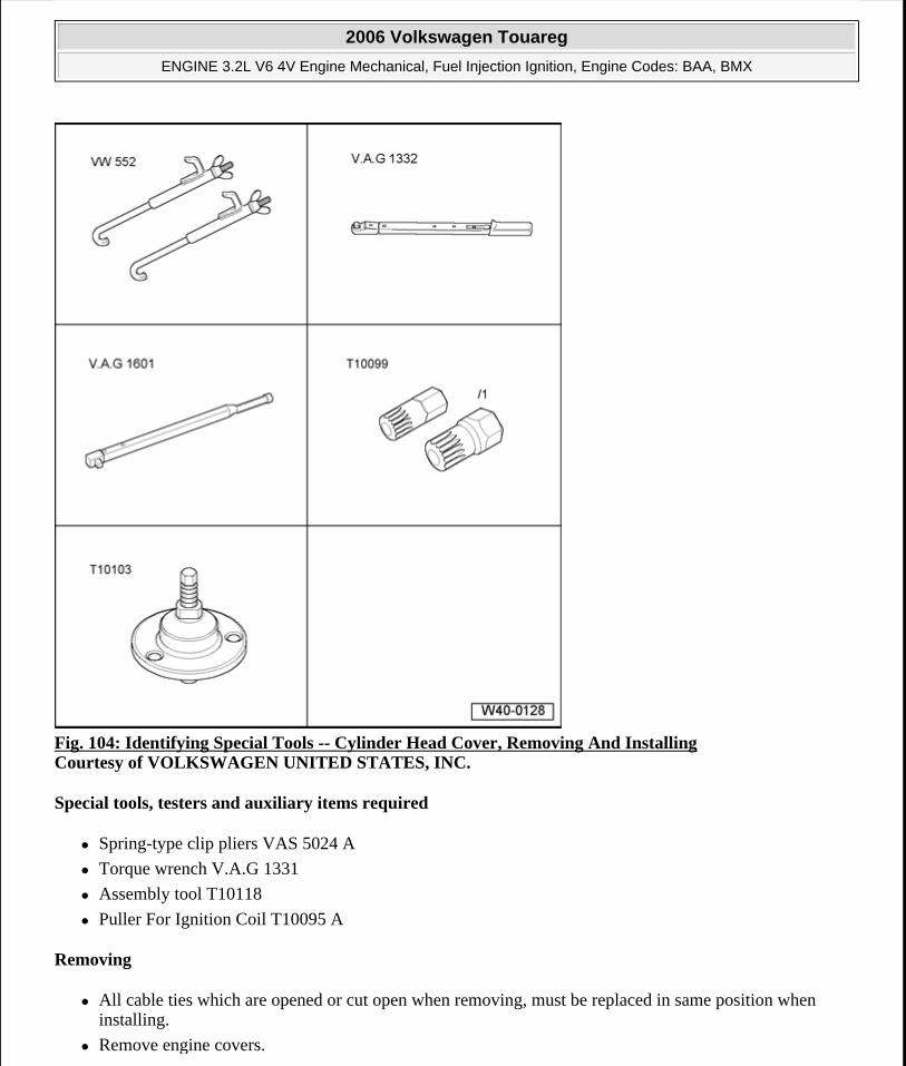
Fig. 104: Identifying Special Tools -- Cylinder Head Cover, Removing And Installing Courtesy of VOLKSWAGEN UNITED STATES, INC.
Special tools, testers and auxiliary items required
Spring-type clip pliers VAS 5024 A
Torque wrench V.A.G 1331
Assembly tool T10118
Puller For Ignition Coil T10095 A
Removing
All cable ties which are opened or cut open when removing, must be replaced in same position when installing.
Remove engine covers.
2006 Volkswagen Touareg
ENGINE 3.2L V6 4V Engine Mechanical, Fuel Injection Ignition, Engine Codes: BAA, BMX
Microsoft
Sunday, September 20, 2009 9:14:17 AM Page 88 © 2005 Mitchell Repair Information Company, LLC.
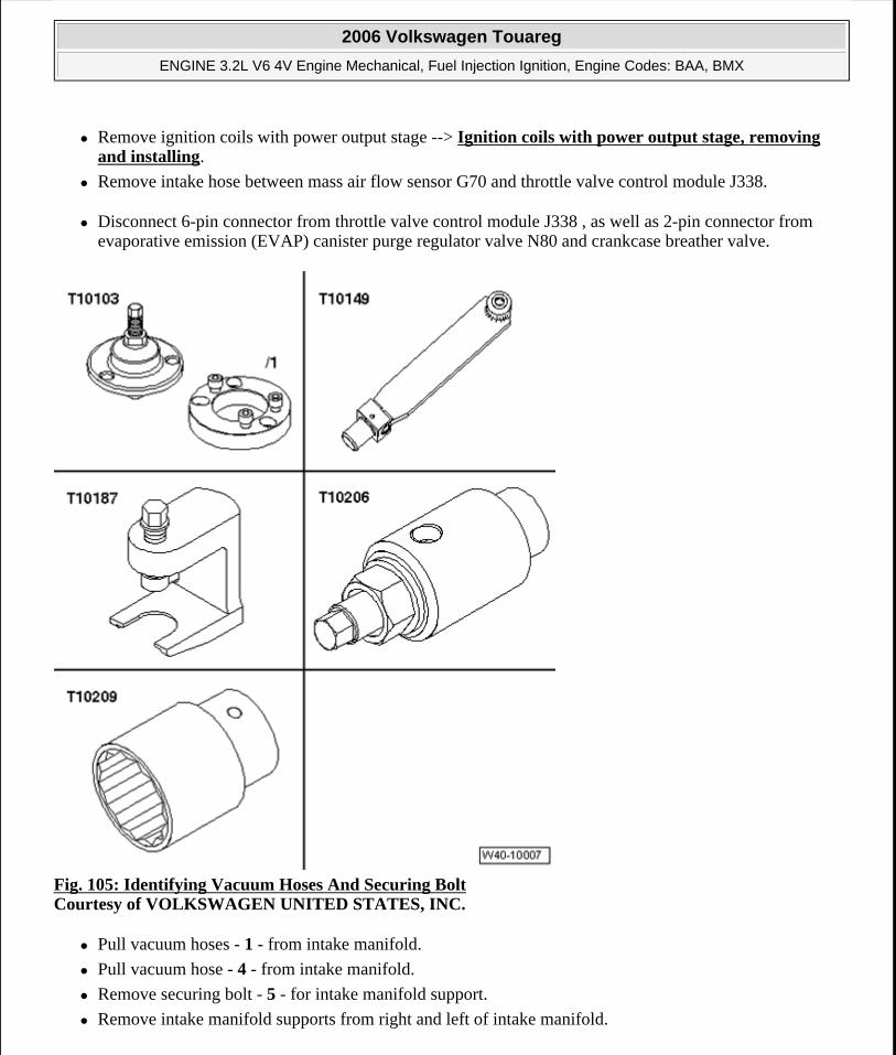
Remove ignition coils with power output stage --> Ignition coils with power output stage, removing and installing.
Remove intake hose between mass air flow sensor G70 and throttle valve control module J338.
Disconnect 6-pin connector from throttle valve control module J338 , as well as 2-pin connector from evaporative emission (EVAP) canister purge regulator valve N80 and crankcase breather valve.
Fig. 105: Identifying Vacuum Hoses And Securing Bolt Courtesy of VOLKSWAGEN UNITED STATES, INC.
Pull vacuum hoses - 1 - from intake manifold.
Pull vacuum hose - 4 - from intake manifold.
Remove securing bolt - 5 - for intake manifold support.
Remove intake manifold supports from right and left of intake manifold.
2006 Volkswagen Touareg
ENGINE 3.2L V6 4V Engine Mechanical, Fuel Injection Ignition, Engine Codes: BAA, BMX
Microsoft
Sunday, September 20, 2009 9:14:17 AM Page 89 © 2005 Mitchell Repair Information Company, LLC.
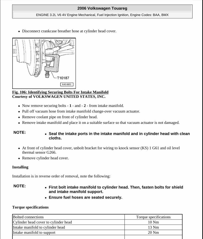
Disconnect crankcase breather hose at cylinder head cover.
Fig. 106: Identifying Securing Bolts For Intake Manifold Courtesy of VOLKSWAGEN UNITED STATES, INC.
Now remove securing bolts - 1 - and - 2 - from intake manifold.
Pull off vacuum hose from intake manifold change-over vacuum actuator.
Remove coolant pipe on front of cylinder head.
Remove intake manifold and place it on a suitable surface so that vacuum actuator is not damaged.
At front of cylinder head cover, unbolt bracket for wiring to knock sensor (KS) 1 G61 and oil level thermal sensor G266.
Remove cylinder head cover.
Installing
Installation is in reverse order of removal, note the following:
Torque specifications
NOTE: Seal the intake ports in the intake manifold and in cylinder head with clean cloths.
NOTE: First bolt intake manifold to cylinder head. Then, fasten bolts for shield and intake manifold support.
Ensure fuel hoses are seated securely.
Bolted connections Torque specificationsCylinder head cover to cylinder head 10 NmIntake manifold to cylinder head 13 NmIntake manifold to support 20 Nm
2006 Volkswagen Touareg
ENGINE 3.2L V6 4V Engine Mechanical, Fuel Injection Ignition, Engine Codes: BAA, BMX
Microsoft
Sunday, September 20, 2009 9:14:17 AM Page 90 © 2005 Mitchell Repair Information Company, LLC.
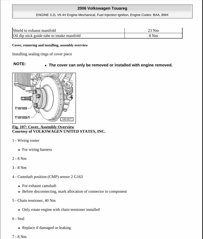
Cover, removing and installing, assembly overview
Installing sealing rings of cover piece
Fig. 107: Cover, Assembly Overview Courtesy of VOLKSWAGEN UNITED STATES, INC.
1 - Wiring router
For wiring harness
2 - 8 Nm
3 - 8 Nm
4 - Camshaft position (CMP) sensor 2 G163
For exhaust camshaft
Before disconnecting, mark allocation of connector to component
5 - Chain tensioner, 40 Nm
Only rotate engine with chain tensioner installed
6 - Seal
Replace if damaged or leaking
7 - 8 Nm
Shield to exhaust manifold 23 NmOil dip stick guide tube to intake manifold 8 Nm
NOTE: The cover can only be removed or installed with engine removed.
2006 Volkswagen Touareg
ENGINE 3.2L V6 4V Engine Mechanical, Fuel Injection Ignition, Engine Codes: BAA, BMX
Microsoft
Sunday, September 20, 2009 9:14:17 AM Page 91 © 2005 Mitchell Repair Information Company, LLC.
8 - Seal
Replace if damaged or leaking
Installing
9 - Bracket
For after-run coolant pump V51
For evaporative emission (EVAP) canister purge regulator valve N80
10 - Coolant thermostat housing
Coolant hose connection diagram --> Coolant hose connection diagram
11 - 23 Nm
12 - Seal
Replace if damaged or leaking
13 - Cover
Prepare cylinder head gasket for installation Preparing cylinder head gasket for installation
14 - Camshaft Position (CMP) sensor G40
For intake camshaft
Before disconnecting, mark allocation of connector to component
15 - O-ring
For oil channel seal
Replace
Oil before assembling
Preparing cylinder head gasket for installation
2006 Volkswagen Touareg
ENGINE 3.2L V6 4V Engine Mechanical, Fuel Injection Ignition, Engine Codes: BAA, BMX
Microsoft
Sunday, September 20, 2009 9:14:17 AM Page 92 © 2005 Mitchell Repair Information Company, LLC.
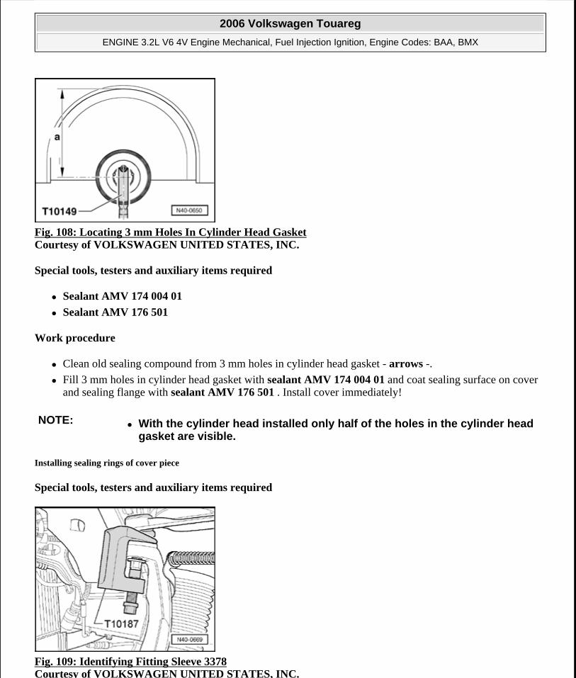
Fig. 108: Locating 3 mm Holes In Cylinder Head Gasket Courtesy of VOLKSWAGEN UNITED STATES, INC.
Special tools, testers and auxiliary items required
Sealant AMV 174 004 01
Sealant AMV 176 501
Work procedure
Clean old sealing compound from 3 mm holes in cylinder head gasket - arrows -.
Fill 3 mm holes in cylinder head gasket with sealant AMV 174 004 01 and coat sealing surface on cover and sealing flange with sealant AMV 176 501 . Install cover immediately!
Installing sealing rings of cover piece
Special tools, testers and auxiliary items required
Fig. 109: Identifying Fitting Sleeve 3378 Courtesy of VOLKSWAGEN UNITED STATES, INC.
NOTE: With the cylinder head installed only half of the holes in the cylinder head gasket are visible.
2006 Volkswagen Touareg
ENGINE 3.2L V6 4V Engine Mechanical, Fuel Injection Ignition, Engine Codes: BAA, BMX
Microsoft
Sunday, September 20, 2009 9:14:17 AM Page 93 © 2005 Mitchell Repair Information Company, LLC.
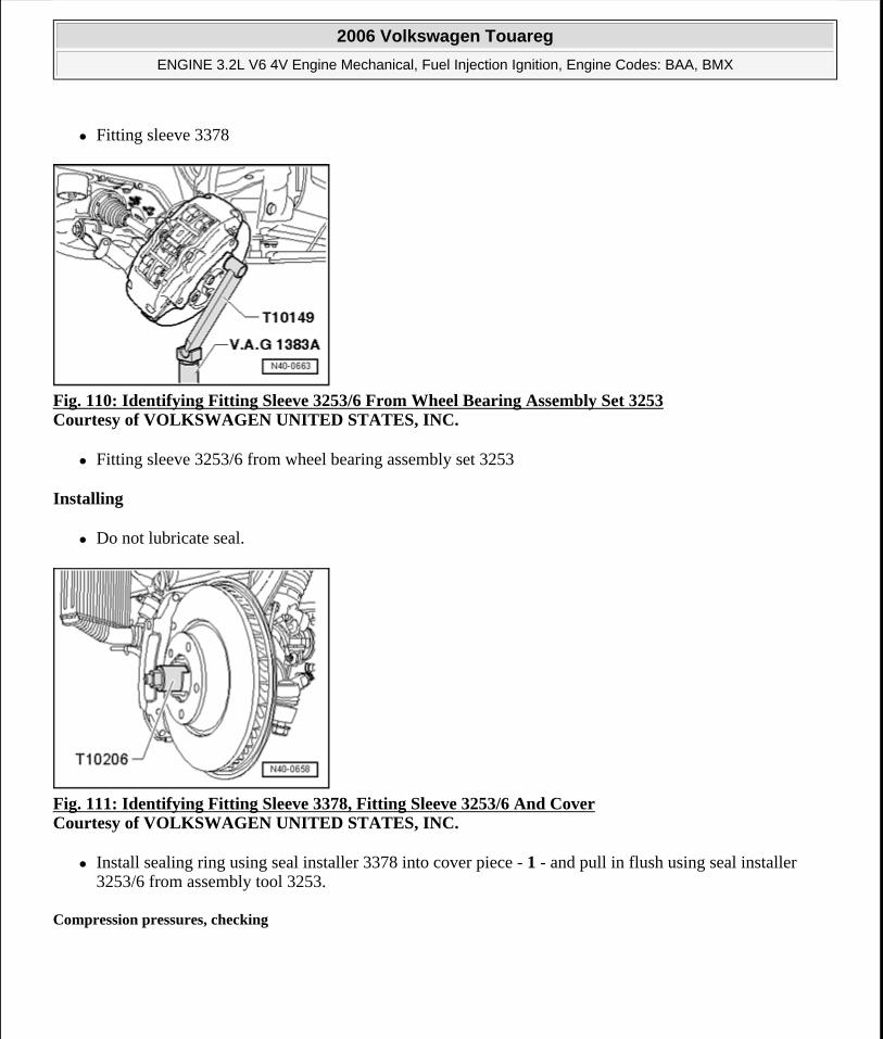
Fitting sleeve 3378
Fig. 110: Identifying Fitting Sleeve 3253/6 From Wheel Bearing Assembly Set 3253 Courtesy of VOLKSWAGEN UNITED STATES, INC.
Fitting sleeve 3253/6 from wheel bearing assembly set 3253
Installing
Do not lubricate seal.
Fig. 111: Identifying Fitting Sleeve 3378, Fitting Sleeve 3253/6 And Cover Courtesy of VOLKSWAGEN UNITED STATES, INC.
Install sealing ring using seal installer 3378 into cover piece - 1 - and pull in flush using seal installer 3253/6 from assembly tool 3253.
Compression pressures, checking
2006 Volkswagen Touareg
ENGINE 3.2L V6 4V Engine Mechanical, Fuel Injection Ignition, Engine Codes: BAA, BMX
Microsoft
Sunday, September 20, 2009 9:14:17 AM Page 94 © 2005 Mitchell Repair Information Company, LLC.
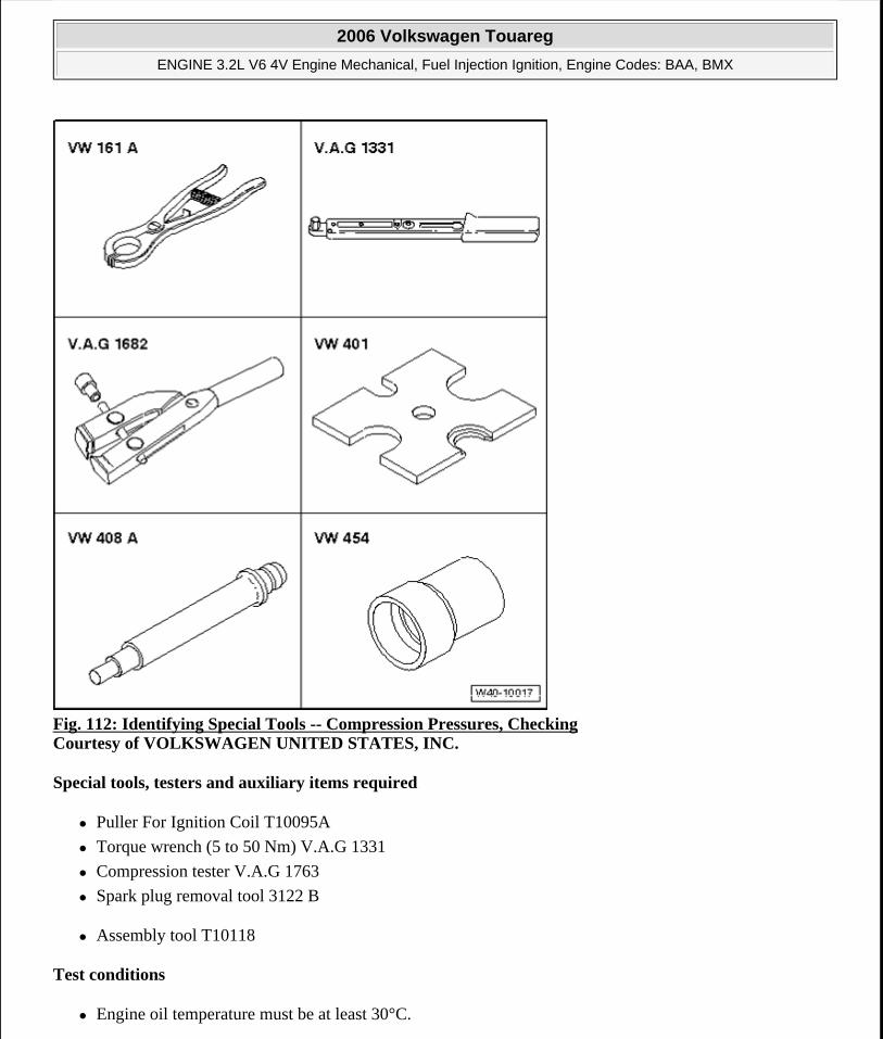
Fig. 112: Identifying Special Tools -- Compression Pressures, Checking Courtesy of VOLKSWAGEN UNITED STATES, INC.
Special tools, testers and auxiliary items required
Puller For Ignition Coil T10095A
Torque wrench (5 to 50 Nm) V.A.G 1331
Compression tester V.A.G 1763
Spark plug removal tool 3122 B
Assembly tool T10118
Test conditions
Engine oil temperature must be at least 30°C.
2006 Volkswagen Touareg
ENGINE 3.2L V6 4V Engine Mechanical, Fuel Injection Ignition, Engine Codes: BAA, BMX
Microsoft
Sunday, September 20, 2009 9:14:17 AM Page 95 © 2005 Mitchell Repair Information Company, LLC.
Battery voltage must be at least 11.5 V.
All electrical consumers such as, for example, lights and rear window defroster must be switched off.
If vehicle is equipped with an air conditioning system, this must be switched off.
For vehicles with automatic transmission, selector lever must be in position "P" or "N".
Fig. 113: Identifying Fuses Courtesy of VOLKSWAGEN UNITED STATES, INC.
Fuses - 13 - and - 14 - - arrows - must be removed from their sockets.
Test sequence
Remove engine cover.
Remove ignition coils with power output stage --> Ignition coils with power output stage, removing and installing.
Remove spark plugs using spark plug removal tool 3122 B.
Check compression pressure using compression tester V.A.G 1763.
Have a second technician fully depress accelerator pedal and crank engine.
Operate starter until tester shows no further pressure increase.
Compression pressure:
New: 10 to 13 bar pressure
Wear limit: 7.5 bar pressure
Permissible difference between all cylinders: 3 bar
Install spark plugs using spark plug removal tool 3122B and tighten to 20 Nm.
NOTE: Using the compression tester Operating instructions.
2006 Volkswagen Touareg
ENGINE 3.2L V6 4V Engine Mechanical, Fuel Injection Ignition, Engine Codes: BAA, BMX
Microsoft
Sunday, September 20, 2009 9:14:17 AM Page 96 © 2005 Mitchell Repair Information Company, LLC.
After completing installation:
Connect Vehicle Diagnosis Serv. System VAS 5052.
Perform vehicle system test "Guided Fault Finding".
End vehicle system test in such a way that possibly existing DTC entries are automatically erased.
Perform road test.
Generate readiness code in conjunction with road test.
Observe safety precautions that apply to road tests.
After that perform vehicle system test again and repair any occurring malfunctions.
VALVETRAIN
Valvetrain
Assembly overview --> Valvetrain, assembly overview
Camshaft, removing and installing --> Camshafts, removing and installing
Replacing valve stem oil seals --> Valve stem seals, replacing
Check valve guides --> Valve guides, checking
Rework valve seats --> Valve seats, reworking
Valve dimensions
Valvetrain, assembly overview
Fig. 114: Valvetrain, Assembly Overview Courtesy of VOLKSWAGEN UNITED STATES, INC.
2006 Volkswagen Touareg
ENGINE 3.2L V6 4V Engine Mechanical, Fuel Injection Ignition, Engine Codes: BAA, BMX
Microsoft
Sunday, September 20, 2009 9:14:17 AM Page 97 © 2005 Mitchell Repair Information Company, LLC.
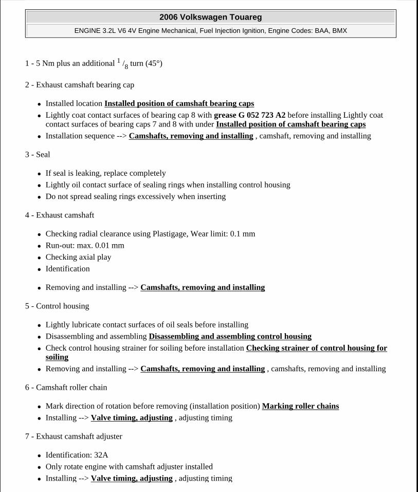
1 - 5 Nm plus an additional 1 /8 turn (45°)
2 - Exhaust camshaft bearing cap
Installed location Installed position of camshaft bearing caps
Lightly coat contact surfaces of bearing cap 8 with grease G 052 723 A2 before installing Lightly coat contact surfaces of bearing caps 7 and 8 with under Installed position of camshaft bearing caps
Installation sequence --> Camshafts, removing and installing , camshaft, removing and installing
3 - Seal
If seal is leaking, replace completely
Lightly oil contact surface of sealing rings when installing control housing
Do not spread sealing rings excessively when inserting
4 - Exhaust camshaft
Checking radial clearance using Plastigage, Wear limit: 0.1 mm
Run-out: max. 0.01 mm
Checking axial play
Identification
Removing and installing --> Camshafts, removing and installing
5 - Control housing
Lightly lubricate contact surfaces of oil seals before installing
Disassembling and assembling Disassembling and assembling control housing
Check control housing strainer for soiling before installation Checking strainer of control housing for soiling
Removing and installing --> Camshafts, removing and installing , camshafts, removing and installing
6 - Camshaft roller chain
Mark direction of rotation before removing (installation position) Marking roller chains
Installing --> Valve timing, adjusting , adjusting timing
7 - Exhaust camshaft adjuster
Identification: 32A
Only rotate engine with camshaft adjuster installed
Installing --> Valve timing, adjusting , adjusting timing
2006 Volkswagen Touareg
ENGINE 3.2L V6 4V Engine Mechanical, Fuel Injection Ignition, Engine Codes: BAA, BMX
Microsoft
Sunday, September 20, 2009 9:14:17 AM Page 98 © 2005 Mitchell Repair Information Company, LLC.
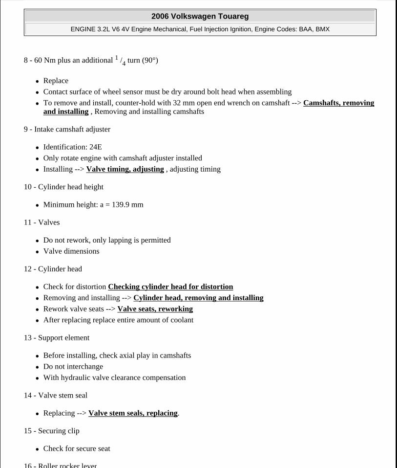
8 - 60 Nm plus an additional 1 /4 turn (90°)
Replace
Contact surface of wheel sensor must be dry around bolt head when assembling
To remove and install, counter-hold with 32 mm open end wrench on camshaft --> Camshafts, removing and installing , Removing and installing camshafts
9 - Intake camshaft adjuster
Identification: 24E
Only rotate engine with camshaft adjuster installed
Installing --> Valve timing, adjusting , adjusting timing
10 - Cylinder head height
Minimum height: a = 139.9 mm
11 - Valves
Do not rework, only lapping is permitted
Valve dimensions
12 - Cylinder head
Check for distortion Checking cylinder head for distortion
Removing and installing --> Cylinder head, removing and installing
Rework valve seats --> Valve seats, reworking
After replacing replace entire amount of coolant
13 - Support element
Before installing, check axial play in camshafts
Do not interchange
With hydraulic valve clearance compensation
14 - Valve stem seal
Replacing --> Valve stem seals, replacing.
15 - Securing clip
Check for secure seat
16 - Roller rocker lever
2006 Volkswagen Touareg
ENGINE 3.2L V6 4V Engine Mechanical, Fuel Injection Ignition, Engine Codes: BAA, BMX
Microsoft
Sunday, September 20, 2009 9:14:17 AM Page 99 © 2005 Mitchell Repair Information Company, LLC.
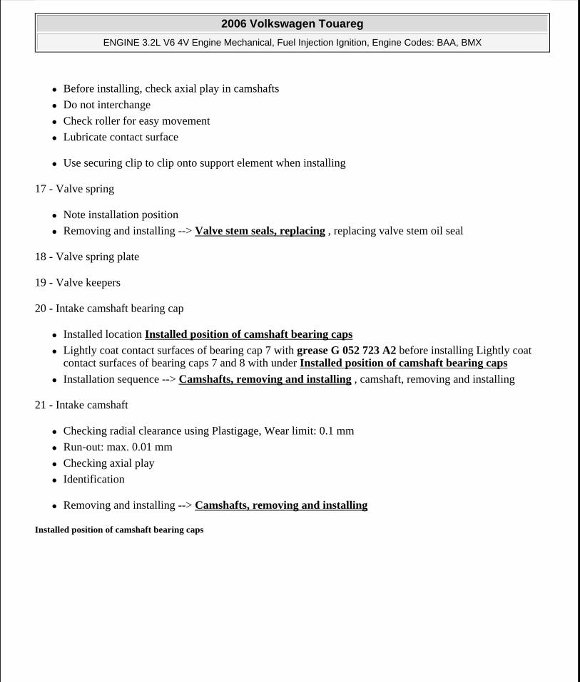
Before installing, check axial play in camshafts
Do not interchange
Check roller for easy movement
Lubricate contact surface
Use securing clip to clip onto support element when installing
17 - Valve spring
Note installation position
Removing and installing --> Valve stem seals, replacing , replacing valve stem oil seal
18 - Valve spring plate
19 - Valve keepers
20 - Intake camshaft bearing cap
Installed location Installed position of camshaft bearing caps
Lightly coat contact surfaces of bearing cap 7 with grease G 052 723 A2 before installing Lightly coat contact surfaces of bearing caps 7 and 8 with under Installed position of camshaft bearing caps
Installation sequence --> Camshafts, removing and installing , camshaft, removing and installing
21 - Intake camshaft
Checking radial clearance using Plastigage, Wear limit: 0.1 mm
Run-out: max. 0.01 mm
Checking axial play
Identification
Removing and installing --> Camshafts, removing and installing
Installed position of camshaft bearing caps
2006 Volkswagen Touareg
ENGINE 3.2L V6 4V Engine Mechanical, Fuel Injection Ignition, Engine Codes: BAA, BMX
Microsoft
Sunday, September 20, 2009 9:14:17 AM Page 100 © 2005 Mitchell Repair Information Company, LLC.
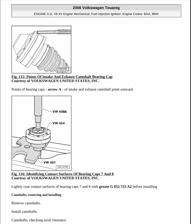
Fig. 115: Points Of Intake And Exhaust Camshaft Bearing Cap Courtesy of VOLKSWAGEN UNITED STATES, INC.
Points of bearing caps - arrow A - of intake and exhaust camshaft point outward.
Fig. 116: Identifying Contact Surfaces Of Bearing Caps 7 And 8 Courtesy of VOLKSWAGEN UNITED STATES, INC.
Lightly coat contact surfaces of bearing caps 7 and 8 with grease G 052 723 A2 before installing
Camshafts, removing and installing
Remove camshafts.
Install camshafts.
Camshafts, checking axial clearance
2006 Volkswagen Touareg
ENGINE 3.2L V6 4V Engine Mechanical, Fuel Injection Ignition, Engine Codes: BAA, BMX
Microsoft
Sunday, September 20, 2009 9:14:17 AM Page 101 © 2005 Mitchell Repair Information Company, LLC.
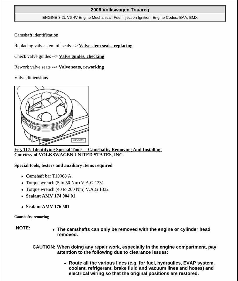
Camshaft identification
Replacing valve stem oil seals --> Valve stem seals, replacing
Check valve guides --> Valve guides, checking
Rework valve seats --> Valve seats, reworking
Valve dimensions
Fig. 117: Identifying Special Tools -- Camshafts, Removing And Installing Courtesy of VOLKSWAGEN UNITED STATES, INC.
Special tools, testers and auxiliary items required
Camshaft bar T10068 A
Torque wrench (5 to 50 Nm) V.A.G 1331
Torque wrench (40 to 200 Nm) V.A.G 1332
Sealant AMV 174 004 01
Sealant AMV 176 501
Camshafts, removing
NOTE: The camshafts can only be removed with the engine or cylinder head removed.
CAUTION: When doing any repair work, especially in the engine compartment, pay attention to the following due to clearance issues:
Route all the various lines (e.g. for fuel, hydraulics, EVAP system, coolant, refrigerant, brake fluid and vacuum lines and hoses) and electrical wiring so that the original positions are restored.
2006 Volkswagen Touareg
ENGINE 3.2L V6 4V Engine Mechanical, Fuel Injection Ignition, Engine Codes: BAA, BMX
Microsoft
Sunday, September 20, 2009 9:14:17 AM Page 102 © 2005 Mitchell Repair Information Company, LLC.
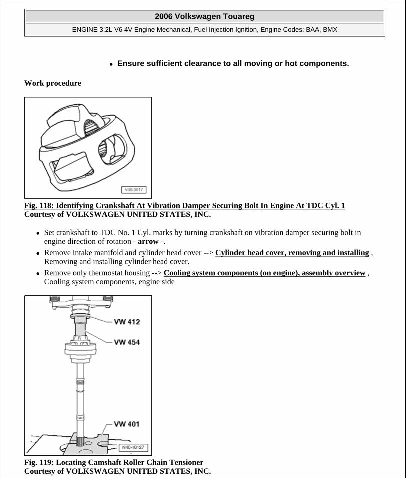
Work procedure
Fig. 118: Identifying Crankshaft At Vibration Damper Securing Bolt In Engine At TDC Cyl. 1 Courtesy of VOLKSWAGEN UNITED STATES, INC.
Set crankshaft to TDC No. 1 Cyl. marks by turning crankshaft on vibration damper securing bolt in engine direction of rotation - arrow -.
Remove intake manifold and cylinder head cover --> Cylinder head cover, removing and installing , Removing and installing cylinder head cover.
Remove only thermostat housing --> Cooling system components (on engine), assembly overview , Cooling system components, engine side
Fig. 119: Locating Camshaft Roller Chain Tensioner Courtesy of VOLKSWAGEN UNITED STATES, INC.
Ensure sufficient clearance to all moving or hot components.
2006 Volkswagen Touareg
ENGINE 3.2L V6 4V Engine Mechanical, Fuel Injection Ignition, Engine Codes: BAA, BMX
Microsoft
Sunday, September 20, 2009 9:14:17 AM Page 103 © 2005 Mitchell Repair Information Company, LLC.
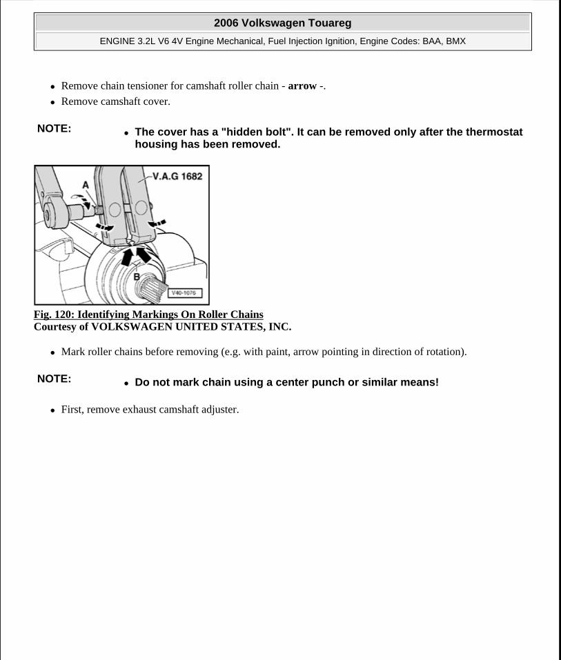
Remove chain tensioner for camshaft roller chain - arrow -.
Remove camshaft cover.
Fig. 120: Identifying Markings On Roller Chains Courtesy of VOLKSWAGEN UNITED STATES, INC.
Mark roller chains before removing (e.g. with paint, arrow pointing in direction of rotation).
First, remove exhaust camshaft adjuster.
NOTE: The cover has a "hidden bolt". It can be removed only after the thermostat housing has been removed.
NOTE: Do not mark chain using a center punch or similar means!
2006 Volkswagen Touareg
ENGINE 3.2L V6 4V Engine Mechanical, Fuel Injection Ignition, Engine Codes: BAA, BMX
Microsoft
Sunday, September 20, 2009 9:14:17 AM Page 104 © 2005 Mitchell Repair Information Company, LLC.
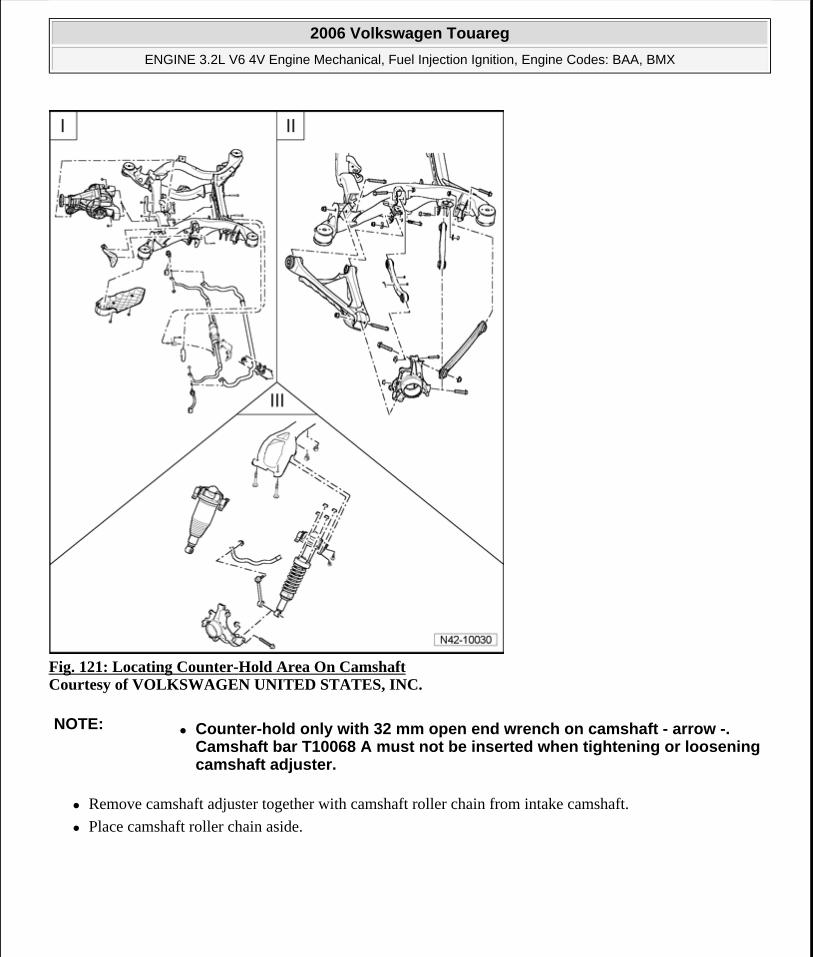
Fig. 121: Locating Counter-Hold Area On Camshaft Courtesy of VOLKSWAGEN UNITED STATES, INC.
Remove camshaft adjuster together with camshaft roller chain from intake camshaft.
Place camshaft roller chain aside.
NOTE: Counter-hold only with 32 mm open end wrench on camshaft - arrow -. Camshaft bar T10068 A must not be inserted when tightening or loosening camshaft adjuster.
2006 Volkswagen Touareg
ENGINE 3.2L V6 4V Engine Mechanical, Fuel Injection Ignition, Engine Codes: BAA, BMX
Microsoft
Sunday, September 20, 2009 9:14:17 AM Page 105 © 2005 Mitchell Repair Information Company, LLC.
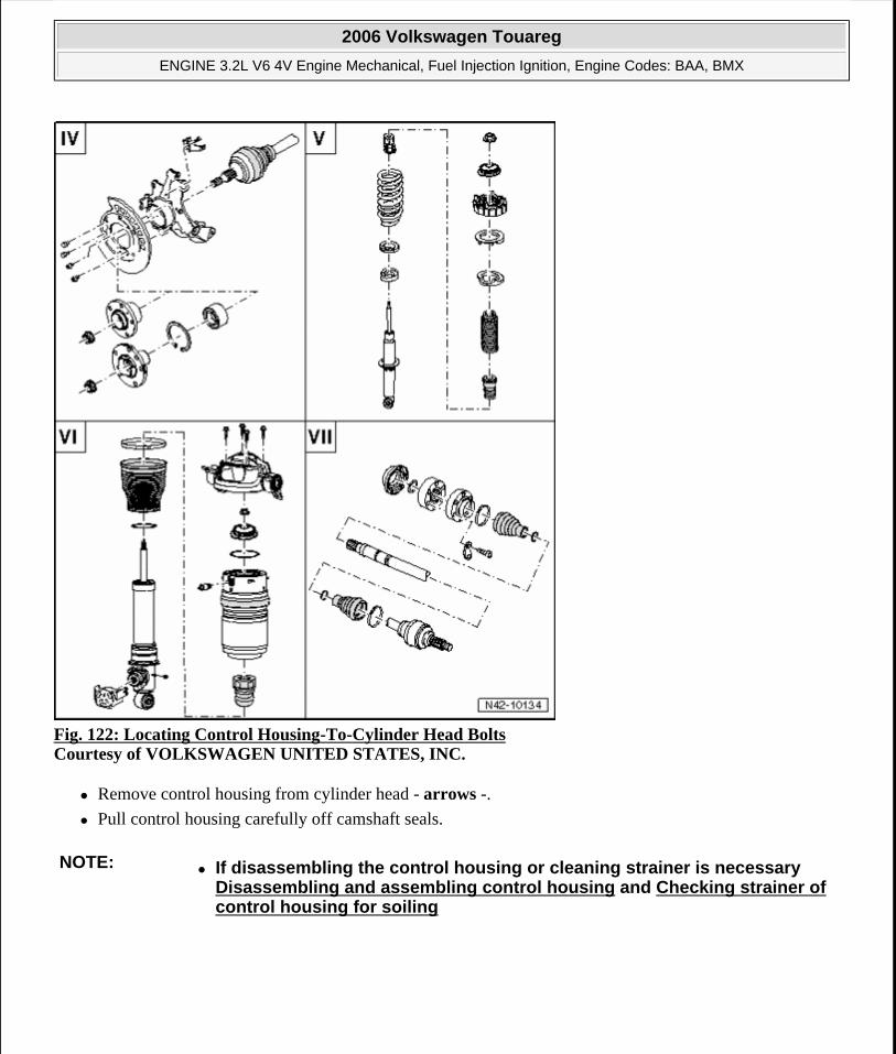
Fig. 122: Locating Control Housing-To-Cylinder Head Bolts Courtesy of VOLKSWAGEN UNITED STATES, INC.
Remove control housing from cylinder head - arrows -.
Pull control housing carefully off camshaft seals.
NOTE: If disassembling the control housing or cleaning strainer is necessary Disassembling and assembling control housing and Checking strainer of control housing for soiling
2006 Volkswagen Touareg
ENGINE 3.2L V6 4V Engine Mechanical, Fuel Injection Ignition, Engine Codes: BAA, BMX
Microsoft
Sunday, September 20, 2009 9:14:17 AM Page 106 © 2005 Mitchell Repair Information Company, LLC.
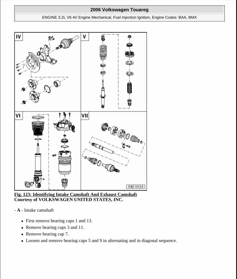
Fig. 123: Identifying Intake Camshaft And Exhaust Camshaft Courtesy of VOLKSWAGEN UNITED STATES, INC.
- A - Intake camshaft
First remove bearing caps 1 and 13.
Remove bearing caps 3 and 11.
Remove bearing cap 7.
Loosen and remove bearing caps 5 and 9 in alternating and in diagonal sequence.
2006 Volkswagen Touareg
ENGINE 3.2L V6 4V Engine Mechanical, Fuel Injection Ignition, Engine Codes: BAA, BMX
Microsoft
Sunday, September 20, 2009 9:14:17 AM Page 107 © 2005 Mitchell Repair Information Company, LLC.
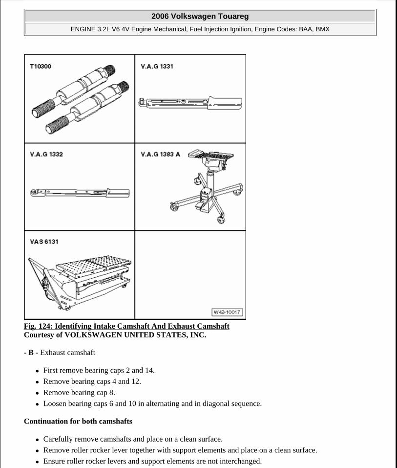
Fig. 124: Identifying Intake Camshaft And Exhaust Camshaft Courtesy of VOLKSWAGEN UNITED STATES, INC.
- B - Exhaust camshaft
First remove bearing caps 2 and 14.
Remove bearing caps 4 and 12.
Remove bearing cap 8.
Loosen bearing caps 6 and 10 in alternating and in diagonal sequence.
Continuation for both camshafts
Carefully remove camshafts and place on a clean surface.
Remove roller rocker lever together with support elements and place on a clean surface.
Ensure roller rocker levers and support elements are not interchanged.
2006 Volkswagen Touareg
ENGINE 3.2L V6 4V Engine Mechanical, Fuel Injection Ignition, Engine Codes: BAA, BMX
Microsoft
Sunday, September 20, 2009 9:14:17 AM Page 108 © 2005 Mitchell Repair Information Company, LLC.
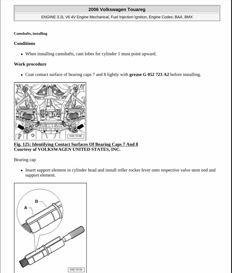
Camshafts, installing
Conditions
When installing camshafts, cam lobes for cylinder 1 must point upward.
Work procedure
Coat contact surface of bearing caps 7 and 8 lightly with grease G 052 723 A2 before installing.
Fig. 125: Identifying Contact Surfaces Of Bearing Caps 7 And 8 Courtesy of VOLKSWAGEN UNITED STATES, INC.
Bearing cap
Insert support element in cylinder head and install roller rocker lever onto respective valve stem end and support element.
2006 Volkswagen Touareg
ENGINE 3.2L V6 4V Engine Mechanical, Fuel Injection Ignition, Engine Codes: BAA, BMX
Microsoft
Sunday, September 20, 2009 9:14:17 AM Page 109 © 2005 Mitchell Repair Information Company, LLC.
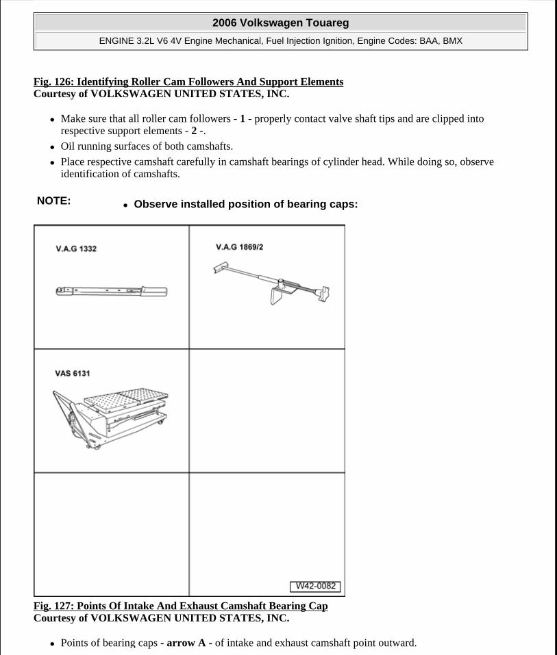
Fig. 126: Identifying Roller Cam Followers And Support ElementsCourtesy of VOLKSWAGEN UNITED STATES, INC.
Make sure that all roller cam followers - 1 - properly contact valve shaft tips and are clipped into respective support elements - 2 -.
Oil running surfaces of both camshafts.
Place respective camshaft carefully in camshaft bearings of cylinder head. While doing so, observe identification of camshafts.
Fig. 127: Points Of Intake And Exhaust Camshaft Bearing Cap Courtesy of VOLKSWAGEN UNITED STATES, INC.
Points of bearing caps - arrow A - of intake and exhaust camshaft point outward.
NOTE: Observe installed position of bearing caps:
2006 Volkswagen Touareg
ENGINE 3.2L V6 4V Engine Mechanical, Fuel Injection Ignition, Engine Codes: BAA, BMX
Microsoft
Sunday, September 20, 2009 9:14:17 AM Page 110 © 2005 Mitchell Repair Information Company, LLC.
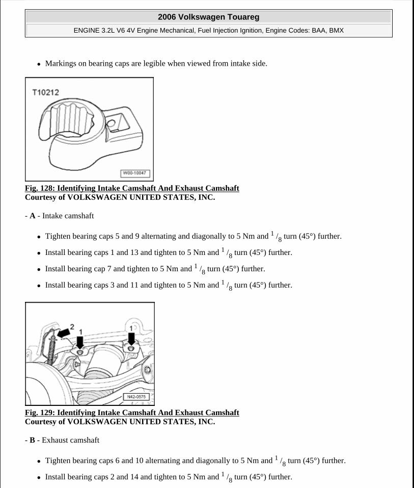
Markings on bearing caps are legible when viewed from intake side.
Fig. 128: Identifying Intake Camshaft And Exhaust Camshaft Courtesy of VOLKSWAGEN UNITED STATES, INC.
- A - Intake camshaft
Tighten bearing caps 5 and 9 alternating and diagonally to 5 Nm and 1 /8 turn (45°) further.
Install bearing caps 1 and 13 and tighten to 5 Nm and 1 /8 turn (45°) further.
Install bearing cap 7 and tighten to 5 Nm and 1 /8 turn (45°) further.
Install bearing caps 3 and 11 and tighten to 5 Nm and 1 /8 turn (45°) further.
Fig. 129: Identifying Intake Camshaft And Exhaust Camshaft Courtesy of VOLKSWAGEN UNITED STATES, INC.
- B - Exhaust camshaft
Tighten bearing caps 6 and 10 alternating and diagonally to 5 Nm and 1 /8 turn (45°) further.
Install bearing caps 2 and 14 and tighten to 5 Nm and 1 /8 turn (45°) further.
2006 Volkswagen Touareg
ENGINE 3.2L V6 4V Engine Mechanical, Fuel Injection Ignition, Engine Codes: BAA, BMX
Microsoft
Sunday, September 20, 2009 9:14:17 AM Page 111 © 2005 Mitchell Repair Information Company, LLC.
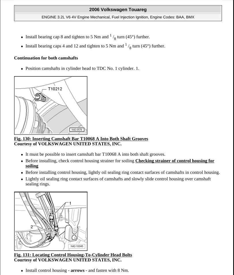
Install bearing cap 8 and tighten to 5 Nm and 1 /8 turn (45°) further.
Install bearing caps 4 and 12 and tighten to 5 Nm and 1 /8 turn (45°) further.
Continuation for both camshafts
Position camshafts in cylinder head to TDC No. 1 cylinder. 1.
Fig. 130: Inserting Camshaft Bar T10068 A Into Both Shaft Grooves Courtesy of VOLKSWAGEN UNITED STATES, INC.
It must be possible to insert camshaft bar T10068 A into both shaft grooves.
Before installing, check control housing strainer for soiling Checking strainer of control housing for soiling
Before installing control housing, lightly oil sealing ring contact surfaces of camshafts in control housing.
Lightly oil sealing ring contact surfaces of camshafts and slowly slide control housing over camshaft sealing rings.
Fig. 131: Locating Control Housing-To-Cylinder Head Bolts Courtesy of VOLKSWAGEN UNITED STATES, INC.
Install control housing - arrows - and fasten with 8 Nm.
2006 Volkswagen Touareg
ENGINE 3.2L V6 4V Engine Mechanical, Fuel Injection Ignition, Engine Codes: BAA, BMX
Microsoft
Sunday, September 20, 2009 9:14:17 AM Page 112 © 2005 Mitchell Repair Information Company, LLC.
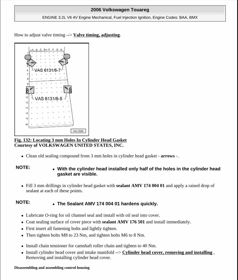
How to adjust valve timing --> Valve timing, adjusting.
Fig. 132: Locating 3 mm Holes In Cylinder Head Gasket Courtesy of VOLKSWAGEN UNITED STATES, INC.
Clean old sealing compound from 3 mm holes in cylinder head gasket - arrows -.
Fill 3 mm drillings in cylinder head gasket with sealant AMV 174 004 01 and apply a raised drop of sealant at each of these points.
Lubricate O-ring for oil channel seal and install with oil seal into cover.
Coat sealing surface of cover piece with sealant AMV 176 501 and install immediately.
First insert all fastening bolts and lightly tighten.
Then tighten bolts M8 to 23 Nm, and tighten bolts M6 to 8 Nm.
Install chain tensioner for camshaft roller chain and tighten to 40 Nm.
Install cylinder head cover and intake manifold --> Cylinder head cover, removing and installing , Removing and installing cylinder head cover.
Disassembling and assembling control housing
NOTE: With the cylinder head installed only half of the holes in the cylinder head gasket are visible.
NOTE: The Sealant AMV 174 004 01 hardens quickly.
2006 Volkswagen Touareg
ENGINE 3.2L V6 4V Engine Mechanical, Fuel Injection Ignition, Engine Codes: BAA, BMX
Microsoft
Sunday, September 20, 2009 9:14:17 AM Page 113 © 2005 Mitchell Repair Information Company, LLC.
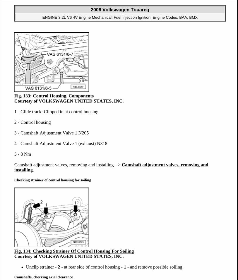
Fig. 133: Control Housing, Components Courtesy of VOLKSWAGEN UNITED STATES, INC.
1 - Glide track: Clipped in at control housing
2 - Control housing
3 - Camshaft Adjustment Valve 1 N205
4 - Camshaft Adjustment Valve 1 (exhaust) N318
5 - 8 Nm
Camshaft adjustment valves, removing and installing --> Camshaft adjustment valves, removing and installing.
Checking strainer of control housing for soiling
Fig. 134: Checking Strainer Of Control Housing For Soiling Courtesy of VOLKSWAGEN UNITED STATES, INC.
Unclip strainer - 2 - at rear side of control housing - 1 - and remove possible soiling.
Camshafts, checking axial clearance
2006 Volkswagen Touareg
ENGINE 3.2L V6 4V Engine Mechanical, Fuel Injection Ignition, Engine Codes: BAA, BMX
Microsoft
Sunday, September 20, 2009 9:14:17 AM Page 114 © 2005 Mitchell Repair Information Company, LLC.
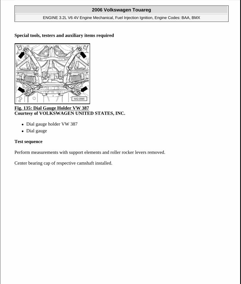
Special tools, testers and auxiliary items required
Fig. 135: Dial Gauge Holder VW 387 Courtesy of VOLKSWAGEN UNITED STATES, INC.
Dial gauge holder VW 387
Dial gauge
Test sequence
Perform measurements with support elements and roller rocker levers removed.
Center bearing cap of respective camshaft installed.
2006 Volkswagen Touareg
ENGINE 3.2L V6 4V Engine Mechanical, Fuel Injection Ignition, Engine Codes: BAA, BMX
Microsoft
Sunday, September 20, 2009 9:14:17 AM Page 115 © 2005 Mitchell Repair Information Company, LLC.
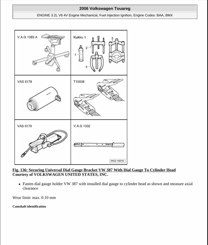
Fig. 136: Securing Universal Dial Gauge Bracket VW 387 With Dial Gauge To Cylinder Head Courtesy of VOLKSWAGEN UNITED STATES, INC.
Fasten dial gauge holder VW 387 with installed dial gauge to cylinder head as shown and measure axial clearance
Wear limit: max. 0.10 mm
Camshaft identification
2006 Volkswagen Touareg
ENGINE 3.2L V6 4V Engine Mechanical, Fuel Injection Ignition, Engine Codes: BAA, BMX
Microsoft
Sunday, September 20, 2009 9:14:17 AM Page 116 © 2005 Mitchell Repair Information Company, LLC.
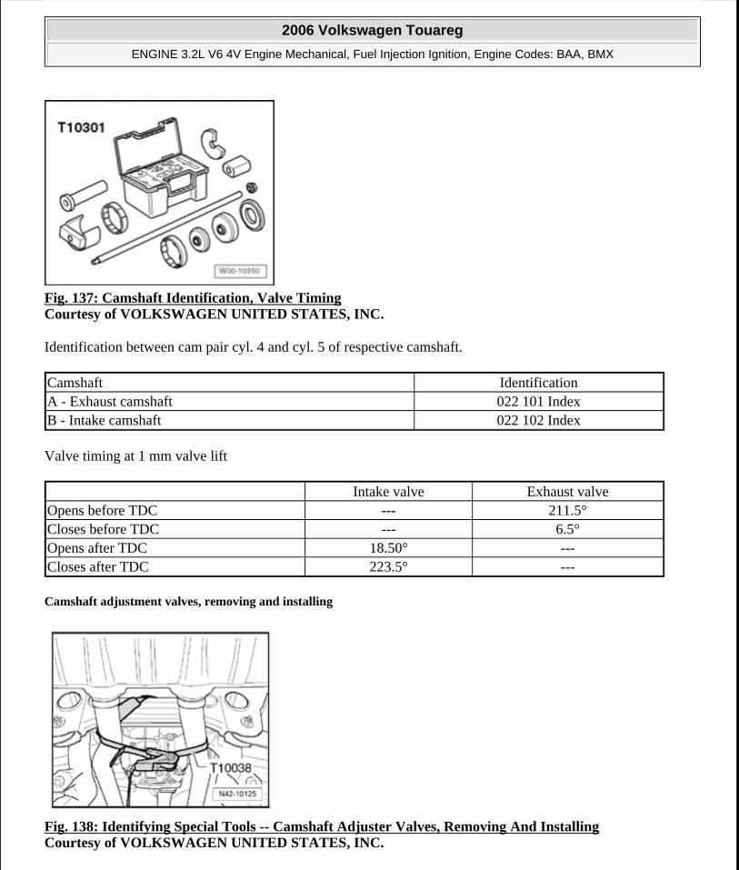
Fig. 137: Camshaft Identification, Valve Timing Courtesy of VOLKSWAGEN UNITED STATES, INC.
Identification between cam pair cyl. 4 and cyl. 5 of respective camshaft.
Valve timing at 1 mm valve lift
Camshaft adjustment valves, removing and installing
Fig. 138: Identifying Special Tools -- Camshaft Adjuster Valves, Removing And Installing Courtesy of VOLKSWAGEN UNITED STATES, INC.
Camshaft IdentificationA - Exhaust camshaft 022 101 IndexB - Intake camshaft 022 102 Index
Intake valve Exhaust valveOpens before TDC --- 211.5°Closes before TDC --- 6.5°Opens after TDC 18.50° ---Closes after TDC 223.5° ---
2006 Volkswagen Touareg
ENGINE 3.2L V6 4V Engine Mechanical, Fuel Injection Ignition, Engine Codes: BAA, BMX
Microsoft
Sunday, September 20, 2009 9:14:17 AM Page 117 © 2005 Mitchell Repair Information Company, LLC.
Special tools, testers and auxiliary items required
Torque wrench V.A.G 1783
Torx bit assortment V.A.G 1766
Ratchet 1/4" VAS 6234
Socket Wrench T10072
Not illustrated:
Special tools, testers and auxiliary items required
Sealant AMV 174 004 01
Sealant AMV 176 501
Removing:
Requirements
Engine must be removed.
Remove cylinder head cover --> Cylinder head cover, removing and installing.
On the following components, remove covers for connectors:
Camshaft Adjustment Valve 1 N205
Camshaft Adjustment Valve 1 (exhaust) N318
Camshaft Position (CMP) sensor G40
Camshaft position (CMP) sensor 2 G163
Free up wiring harness.
Remove only thermostat housing --> Cooling system components (on engine), assembly overview , Cooling system components, engine side
NOTE: Before disconnecting harness connectors, mark allocation to component.
NOTE: The cover has a "hidden bolt". It can be removed only after thermostat housing has been removed.
2006 Volkswagen Touareg
ENGINE 3.2L V6 4V Engine Mechanical, Fuel Injection Ignition, Engine Codes: BAA, BMX
Microsoft
Sunday, September 20, 2009 9:14:17 AM Page 118 © 2005 Mitchell Repair Information Company, LLC.
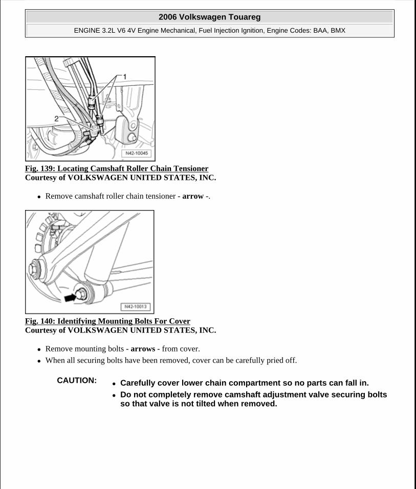
Fig. 139: Locating Camshaft Roller Chain Tensioner Courtesy of VOLKSWAGEN UNITED STATES, INC.
Remove camshaft roller chain tensioner - arrow -.
Fig. 140: Identifying Mounting Bolts For Cover Courtesy of VOLKSWAGEN UNITED STATES, INC.
Remove mounting bolts - arrows - from cover.
When all securing bolts have been removed, cover can be carefully pried off.
CAUTION: Carefully cover lower chain compartment so no parts can fall in.
Do not completely remove camshaft adjustment valve securing bolts so that valve is not tilted when removed.
2006 Volkswagen Touareg
ENGINE 3.2L V6 4V Engine Mechanical, Fuel Injection Ignition, Engine Codes: BAA, BMX
Microsoft
Sunday, September 20, 2009 9:14:17 AM Page 119 © 2005 Mitchell Repair Information Company, LLC.
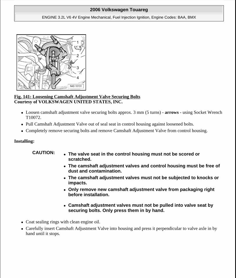
Fig. 141: Loosening Camshaft Adjustment Valve Securing Bolts Courtesy of VOLKSWAGEN UNITED STATES, INC.
Loosen camshaft adjustment valve securing bolts approx. 3 mm (5 turns) - arrows - using Socket Wrench T10072.
Pull Camshaft Adjustment Valve out of seal seat in control housing against loosened bolts.
Completely remove securing bolts and remove Camshaft Adjustment Valve from control housing.
Installing:
Coat sealing rings with clean engine oil.
Carefully insert Camshaft Adjustment Valve into housing and press it perpendicular to valve axle in by hand until it stops.
CAUTION: The valve seat in the control housing must not be scored or scratched.
The camshaft adjustment valves and control housing must be free of dust and contamination.
The camshaft adjustment valves must not be subjected to knocks or impacts.
Only remove new camshaft adjustment valve from packaging right before installation.
Camshaft adjustment valves must not be pulled into valve seat by securing bolts. Only press them in by hand.
2006 Volkswagen Touareg
ENGINE 3.2L V6 4V Engine Mechanical, Fuel Injection Ignition, Engine Codes: BAA, BMX
Microsoft
Sunday, September 20, 2009 9:14:17 AM Page 120 © 2005 Mitchell Repair Information Company, LLC.
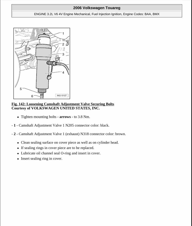
Fig. 142: Loosening Camshaft Adjustment Valve Securing Bolts Courtesy of VOLKSWAGEN UNITED STATES, INC.
Tighten mounting bolts - arrows - to 3.8 Nm.
- 1 - Camshaft Adjustment Valve 1 N205 connector color: black.
- 2 - Camshaft Adjustment Valve 1 (exhaust) N318 connector color: brown.
Clean sealing surface on cover piece as well as on cylinder head.
If sealing rings in cover piece are to be replaced.
Lubricate oil channel seal O-ring and insert in cover.
Insert sealing ring in cover.
2006 Volkswagen Touareg
ENGINE 3.2L V6 4V Engine Mechanical, Fuel Injection Ignition, Engine Codes: BAA, BMX
Microsoft
Sunday, September 20, 2009 9:14:17 AM Page 121 © 2005 Mitchell Repair Information Company, LLC.
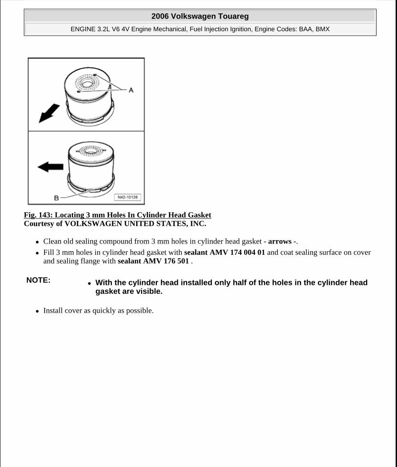
Fig. 143: Locating 3 mm Holes In Cylinder Head Gasket Courtesy of VOLKSWAGEN UNITED STATES, INC.
Clean old sealing compound from 3 mm holes in cylinder head gasket - arrows -.
Fill 3 mm holes in cylinder head gasket with sealant AMV 174 004 01 and coat sealing surface on cover and sealing flange with sealant AMV 176 501 .
Install cover as quickly as possible.
NOTE: With the cylinder head installed only half of the holes in the cylinder head gasket are visible.
2006 Volkswagen Touareg
ENGINE 3.2L V6 4V Engine Mechanical, Fuel Injection Ignition, Engine Codes: BAA, BMX
Microsoft
Sunday, September 20, 2009 9:14:17 AM Page 122 © 2005 Mitchell Repair Information Company, LLC.
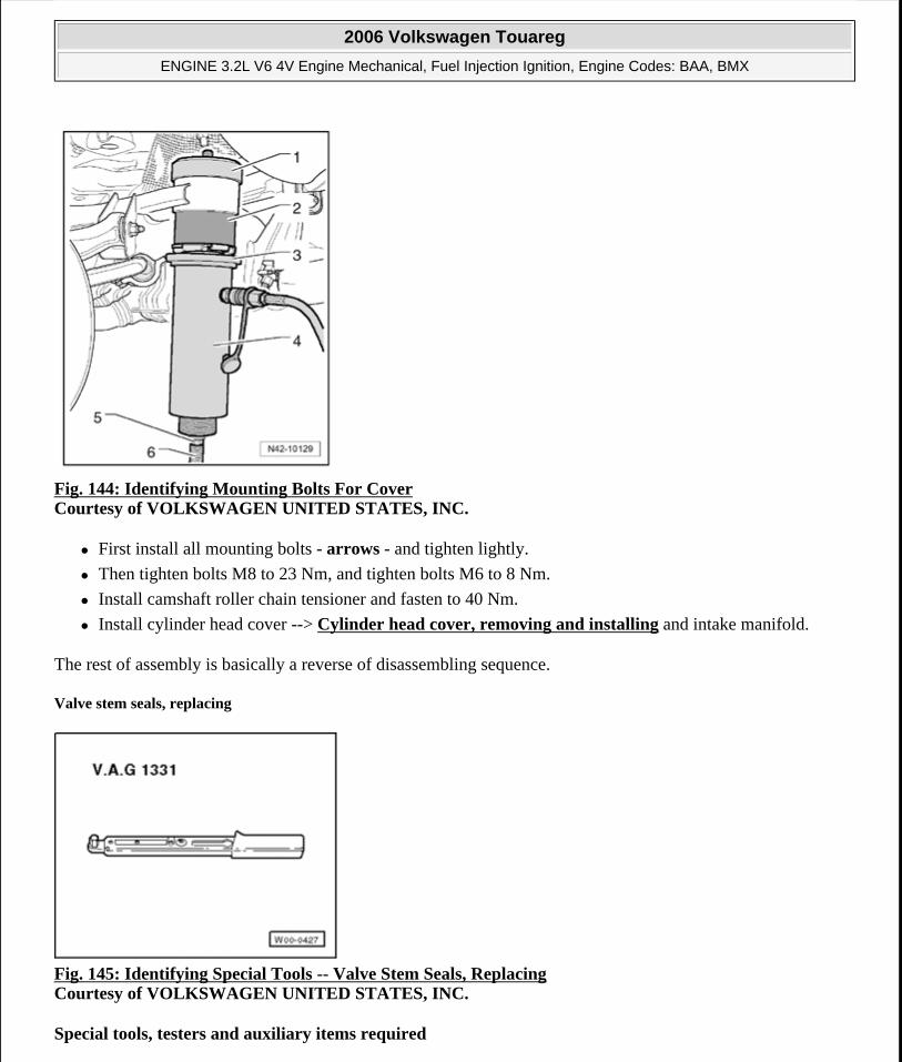
Fig. 144: Identifying Mounting Bolts For Cover Courtesy of VOLKSWAGEN UNITED STATES, INC.
First install all mounting bolts - arrows - and tighten lightly.
Then tighten bolts M8 to 23 Nm, and tighten bolts M6 to 8 Nm.
Install camshaft roller chain tensioner and fasten to 40 Nm.
Install cylinder head cover --> Cylinder head cover, removing and installing and intake manifold.
The rest of assembly is basically a reverse of disassembling sequence.
Valve stem seals, replacing
Fig. 145: Identifying Special Tools -- Valve Stem Seals, Replacing Courtesy of VOLKSWAGEN UNITED STATES, INC.
Special tools, testers and auxiliary items required
2006 Volkswagen Touareg
ENGINE 3.2L V6 4V Engine Mechanical, Fuel Injection Ignition, Engine Codes: BAA, BMX
Microsoft
Sunday, September 20, 2009 9:14:17 AM Page 123 © 2005 Mitchell Repair Information Company, LLC.
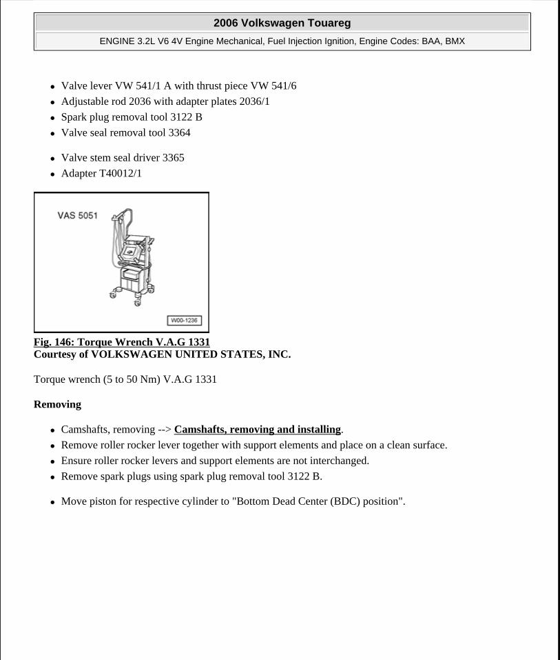
Valve lever VW 541/1 A with thrust piece VW 541/6
Adjustable rod 2036 with adapter plates 2036/1
Spark plug removal tool 3122 B
Valve seal removal tool 3364
Valve stem seal driver 3365
Adapter T40012/1
Fig. 146: Torque Wrench V.A.G 1331 Courtesy of VOLKSWAGEN UNITED STATES, INC.
Torque wrench (5 to 50 Nm) V.A.G 1331
Removing
Camshafts, removing --> Camshafts, removing and installing.
Remove roller rocker lever together with support elements and place on a clean surface.
Ensure roller rocker levers and support elements are not interchanged.
Remove spark plugs using spark plug removal tool 3122 B.
Move piston for respective cylinder to "Bottom Dead Center (BDC) position".
2006 Volkswagen Touareg
ENGINE 3.2L V6 4V Engine Mechanical, Fuel Injection Ignition, Engine Codes: BAA, BMX
Microsoft
Sunday, September 20, 2009 9:14:17 AM Page 124 © 2005 Mitchell Repair Information Company, LLC.
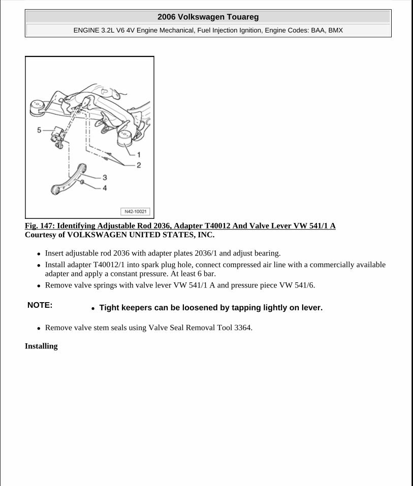
Fig. 147: Identifying Adjustable Rod 2036, Adapter T40012 And Valve Lever VW 541/1 A Courtesy of VOLKSWAGEN UNITED STATES, INC.
Insert adjustable rod 2036 with adapter plates 2036/1 and adjust bearing.
Install adapter T40012/1 into spark plug hole, connect compressed air line with a commercially available adapter and apply a constant pressure. At least 6 bar.
Remove valve springs with valve lever VW 541/1 A and pressure piece VW 541/6.
Remove valve stem seals using Valve Seal Removal Tool 3364.
Installing
NOTE: Tight keepers can be loosened by tapping lightly on lever.
2006 Volkswagen Touareg
ENGINE 3.2L V6 4V Engine Mechanical, Fuel Injection Ignition, Engine Codes: BAA, BMX
Microsoft
Sunday, September 20, 2009 9:14:17 AM Page 125 © 2005 Mitchell Repair Information Company, LLC.
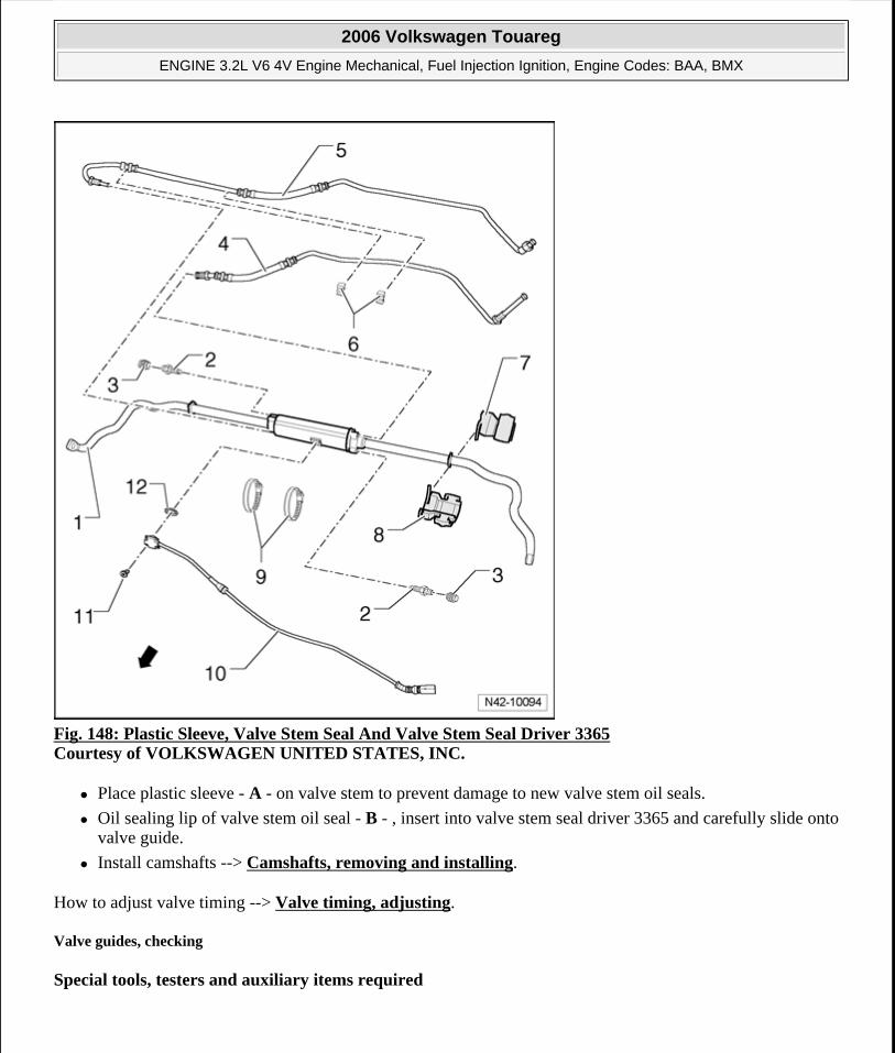
Fig. 148: Plastic Sleeve, Valve Stem Seal And Valve Stem Seal Driver 3365 Courtesy of VOLKSWAGEN UNITED STATES, INC.
Place plastic sleeve - A - on valve stem to prevent damage to new valve stem oil seals.
Oil sealing lip of valve stem oil seal - B - , insert into valve stem seal driver 3365 and carefully slide onto valve guide.
Install camshafts --> Camshafts, removing and installing.
How to adjust valve timing --> Valve timing, adjusting.
Valve guides, checking
Special tools, testers and auxiliary items required
2006 Volkswagen Touareg
ENGINE 3.2L V6 4V Engine Mechanical, Fuel Injection Ignition, Engine Codes: BAA, BMX
Microsoft
Sunday, September 20, 2009 9:14:17 AM Page 126 © 2005 Mitchell Repair Information Company, LLC.
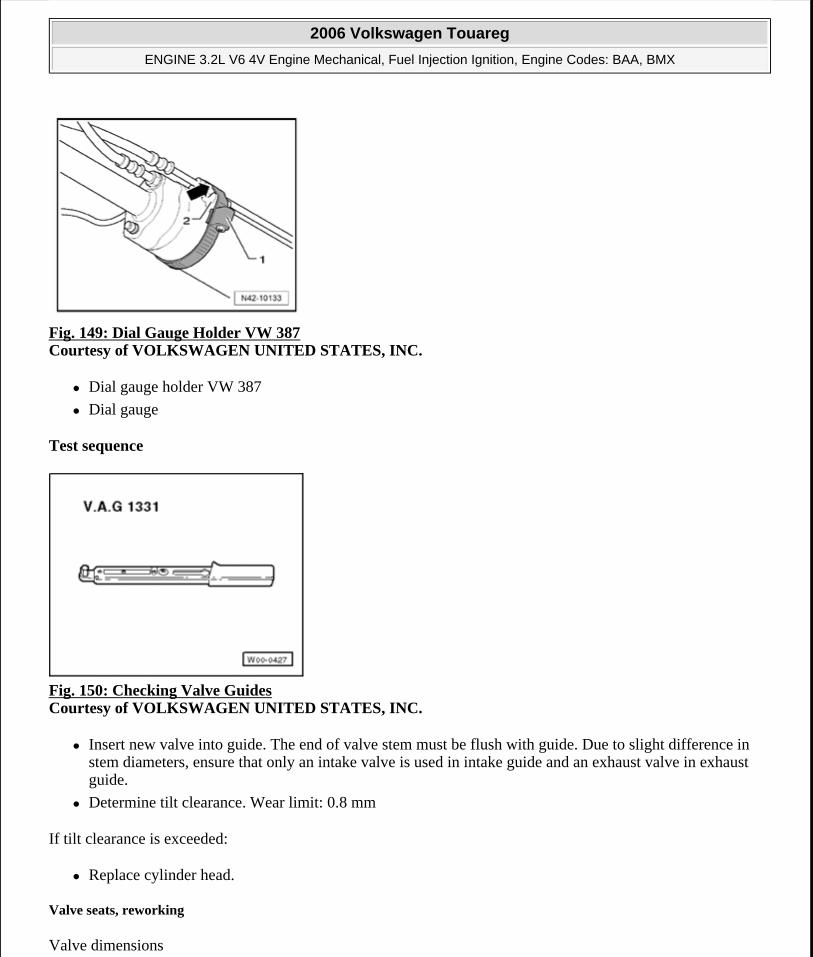
Fig. 149: Dial Gauge Holder VW 387 Courtesy of VOLKSWAGEN UNITED STATES, INC.
Dial gauge holder VW 387
Dial gauge
Test sequence
Fig. 150: Checking Valve Guides Courtesy of VOLKSWAGEN UNITED STATES, INC.
Insert new valve into guide. The end of valve stem must be flush with guide. Due to slight difference in stem diameters, ensure that only an intake valve is used in intake guide and an exhaust valve in exhaust guide.
Determine tilt clearance. Wear limit: 0.8 mm
If tilt clearance is exceeded:
Replace cylinder head.
Valve seats, reworking
Valve dimensions
2006 Volkswagen Touareg
ENGINE 3.2L V6 4V Engine Mechanical, Fuel Injection Ignition, Engine Codes: BAA, BMX
Microsoft
Sunday, September 20, 2009 9:14:17 AM Page 127 © 2005 Mitchell Repair Information Company, LLC.
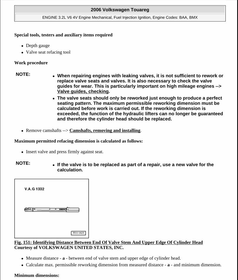
Special tools, testers and auxiliary items required
Depth gauge
Valve seat refacing tool
Work procedure
Remove camshafts --> Camshafts, removing and installing.
Maximum permitted refacing dimension is calculated as follows:
Insert valve and press firmly against seat.
Fig. 151: Identifying Distance Between End Of Valve Stem And Upper Edge Of Cylinder Head Courtesy of VOLKSWAGEN UNITED STATES, INC.
Measure distance - a - between end of valve stem and upper edge of cylinder head.
Calculate max. permissible reworking dimension from measured distance - a - and minimum dimension.
Minimum dimensions:
NOTE: When repairing engines with leaking valves, it is not sufficient to rework or replace valve seats and valves. It is also necessary to check the valve guides for wear. This is particularly important on high mileage engines --> Valve guides, checking.
The valve seats should only be reworked just enough to produce a perfect seating pattern. The maximum permissible reworking dimension must be calculated before work is carried out. If the reworking dimension is exceeded, the function of the hydraulic lifters can no longer be guaranteed and therefore the cylinder head should be replaced.
NOTE: If the valve is to be replaced as part of a repair, use a new valve for the calculation.
2006 Volkswagen Touareg
ENGINE 3.2L V6 4V Engine Mechanical, Fuel Injection Ignition, Engine Codes: BAA, BMX
Microsoft
Sunday, September 20, 2009 9:14:17 AM Page 128 © 2005 Mitchell Repair Information Company, LLC.
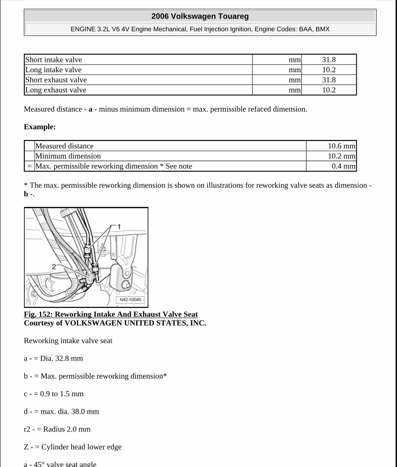
Measured distance - a - minus minimum dimension = max. permissible refaced dimension.
Example:
* The max. permissible reworking dimension is shown on illustrations for reworking valve seats as dimension - b -.
Fig. 152: Reworking Intake And Exhaust Valve Seat Courtesy of VOLKSWAGEN UNITED STATES, INC.
Reworking intake valve seat
a - = Dia. 32.8 mm
b - = Max. permissible reworking dimension*
c - = 0.9 to 1.5 mm
d - = max. dia. 38.0 mm
r2 - = Radius 2.0 mm
Z - = Cylinder head lower edge
a - 45° valve seat angle
Short intake valve mm 31.8Long intake valve mm 10.2Short exhaust valve mm 31.8Long exhaust valve mm 10.2
Measured distance 10.6 mm Minimum dimension 10.2 mm= Max. permissible reworking dimension * See note 0.4 mm
2006 Volkswagen Touareg
ENGINE 3.2L V6 4V Engine Mechanical, Fuel Injection Ignition, Engine Codes: BAA, BMX
Microsoft
Sunday, September 20, 2009 9:14:17 AM Page 129 © 2005 Mitchell Repair Information Company, LLC.
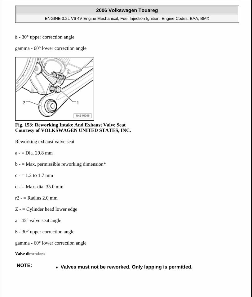
ß - 30° upper correction angle
gamma - 60° lower correction angle
Fig. 153: Reworking Intake And Exhaust Valve Seat Courtesy of VOLKSWAGEN UNITED STATES, INC.
Reworking exhaust valve seat
a - = Dia. 29.8 mm
b - = Max. permissible reworking dimension*
c - = 1.2 to 1.7 mm
d - = Max. dia. 35.0 mm
r2 - = Radius 2.0 mm
Z - = Cylinder head lower edge
a - 45° valve seat angle
ß - 30° upper correction angle
gamma - 60° lower correction angle
Valve dimensions
NOTE: Valves must not be reworked. Only lapping is permitted.
2006 Volkswagen Touareg
ENGINE 3.2L V6 4V Engine Mechanical, Fuel Injection Ignition, Engine Codes: BAA, BMX
Microsoft
Sunday, September 20, 2009 9:14:17 AM Page 130 © 2005 Mitchell Repair Information Company, LLC.
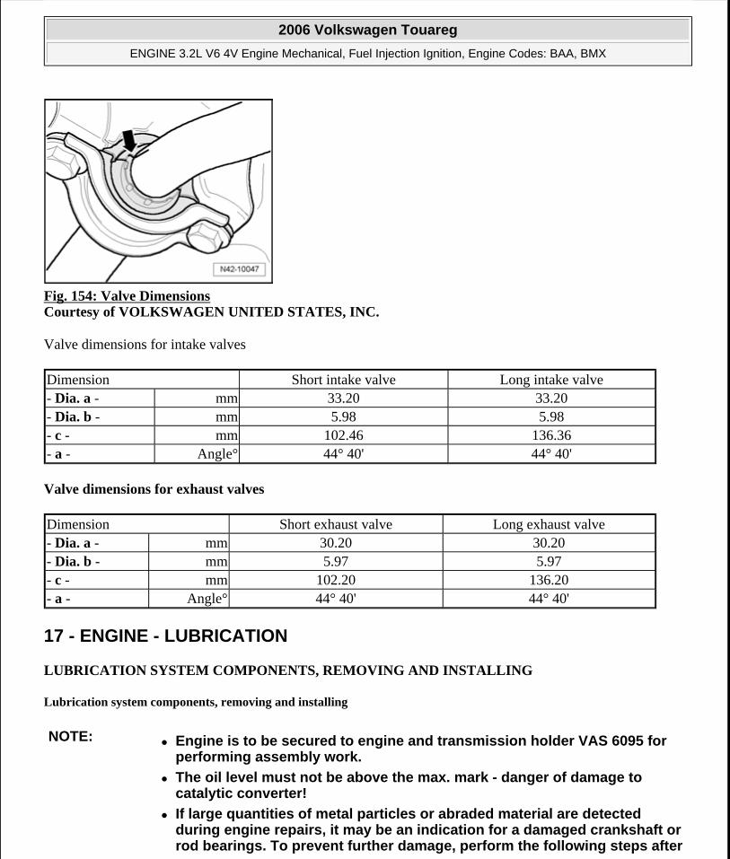
Fig. 154: Valve Dimensions Courtesy of VOLKSWAGEN UNITED STATES, INC.
Valve dimensions for intake valves
Valve dimensions for exhaust valves
17 - ENGINE - LUBRICATION
LUBRICATION SYSTEM COMPONENTS, REMOVING AND INSTALLING
Lubrication system components, removing and installing
Dimension Short intake valve Long intake valve- Dia. a - mm 33.20 33.20- Dia. b - mm 5.98 5.98- c - mm 102.46 136.36- a - Angle° 44° 40' 44° 40'
Dimension Short exhaust valve Long exhaust valve- Dia. a - mm 30.20 30.20- Dia. b - mm 5.97 5.97- c - mm 102.20 136.20- a - Angle° 44° 40' 44° 40'
NOTE: Engine is to be secured to engine and transmission holder VAS 6095 for performing assembly work.
The oil level must not be above the max. mark - danger of damage to catalytic converter!
If large quantities of metal particles or abraded material are detected during engine repairs, it may be an indication for a damaged crankshaft or rod bearings. To prevent further damage, perform the following steps after
2006 Volkswagen Touareg
ENGINE 3.2L V6 4V Engine Mechanical, Fuel Injection Ignition, Engine Codes: BAA, BMX
Microsoft
Sunday, September 20, 2009 9:14:17 AM Page 131 © 2005 Mitchell Repair Information Company, LLC.
Replace oil check valve
Replace oil injection jets
Replace oil cooler
Replace oil filter
Assembly overview --> Assembly overview
Checking oil pressure and oil pressure switch --> Oil pressure and oil pressure switch, checking.
Replace oil non-return valve.
Oil filling quantities
With oil filter 6.3 ltr.
Engine oil specifications:
Use "long life engine oils" in compliance with VW standard 503 00 .
Assembly overview
Engine bracket and left/right engine mounts, removing and installing
the repair:
Carefully clean oil passages
NOTE: The engine is filled at the factory with engine oil complying to VW standard 503 00.
Engine oils complying to VW standards 502 00 may continue to be used. These oils must be changed every 12 months or every 15,000 km.
For changing, engine oil "ILSAC GF3 with viscosity rating SAE 5W-40" can be used. The Service Reminder Indicator (SRI) must be programmed accordingly. Procedure: --> 01 - MAINTENANCE
For topping off, engine oil "ILSAC GF3 with viscosity rating SAE 5W-30" can be used.
2006 Volkswagen Touareg
ENGINE 3.2L V6 4V Engine Mechanical, Fuel Injection Ignition, Engine Codes: BAA, BMX
Microsoft
Sunday, September 20, 2009 9:14:17 AM Page 132 © 2005 Mitchell Repair Information Company, LLC.
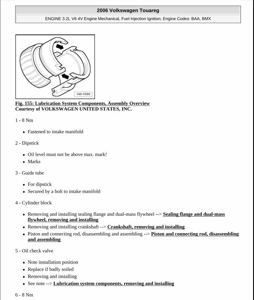
Fig. 155: Lubrication System Components, Assembly Overview Courtesy of VOLKSWAGEN UNITED STATES, INC.
1 - 8 Nm
Fastened to intake manifold
2 - Dipstick
Oil level must not be above max. mark!
Marks
3 - Guide tube
For dipstick
Secured by a bolt to intake manifold
4 - Cylinder block
Removing and installing sealing flange and dual-mass flywheel --> Sealing flange and dual-mass flywheel, removing and installing
Removing and installing crankshaft --> Crankshaft, removing and installing
Piston and connecting rod, disassembling and assembling --> Piston and connecting rod, disassembling and assembling
5 - Oil check valve
Note installation position
Replace if badly soiled
Removing and installing
See note --> Lubrication system components, removing and installing
6 - 8 Nm
2006 Volkswagen Touareg
ENGINE 3.2L V6 4V Engine Mechanical, Fuel Injection Ignition, Engine Codes: BAA, BMX
Microsoft
Sunday, September 20, 2009 9:14:17 AM Page 133 © 2005 Mitchell Repair Information Company, LLC.
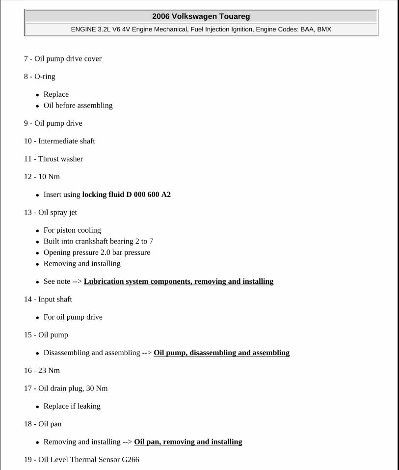
7 - Oil pump drive cover
8 - O-ring
Replace
Oil before assembling
9 - Oil pump drive
10 - Intermediate shaft
11 - Thrust washer
12 - 10 Nm
Insert using locking fluid D 000 600 A2
13 - Oil spray jet
For piston cooling
Built into crankshaft bearing 2 to 7
Opening pressure 2.0 bar pressure
Removing and installing
See note --> Lubrication system components, removing and installing
14 - Input shaft
For oil pump drive
15 - Oil pump
Disassembling and assembling --> Oil pump, disassembling and assembling
16 - 23 Nm
17 - Oil drain plug, 30 Nm
Replace if leaking
18 - Oil pan
Removing and installing --> Oil pan, removing and installing
19 - Oil Level Thermal Sensor G266
2006 Volkswagen Touareg
ENGINE 3.2L V6 4V Engine Mechanical, Fuel Injection Ignition, Engine Codes: BAA, BMX
Microsoft
Sunday, September 20, 2009 9:14:18 AM Page 134 © 2005 Mitchell Repair Information Company, LLC.
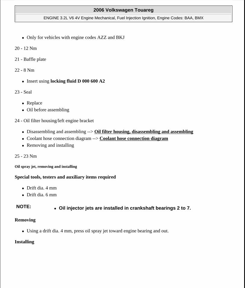
Only for vehicles with engine codes AZZ and BKJ
20 - 12 Nm
21 - Baffle plate
22 - 8 Nm
Insert using locking fluid D 000 600 A2
23 - Seal
Replace
Oil before assembling
24 - Oil filter housing/left engine bracket
Disassembling and assembling --> Oil filter housing, disassembling and assembling
Coolant hose connection diagram --> Coolant hose connection diagram
Removing and installing
25 - 23 Nm
Oil spray jet, removing and installing
Special tools, testers and auxiliary items required
Drift dia. 4 mm
Drift dia. 6 mm
Removing
Using a drift dia. 4 mm, press oil spray jet toward engine bearing and out.
Installing
NOTE: Oil injector jets are installed in crankshaft bearings 2 to 7.
2006 Volkswagen Touareg
ENGINE 3.2L V6 4V Engine Mechanical, Fuel Injection Ignition, Engine Codes: BAA, BMX
Microsoft
Sunday, September 20, 2009 9:14:18 AM Page 135 © 2005 Mitchell Repair Information Company, LLC.
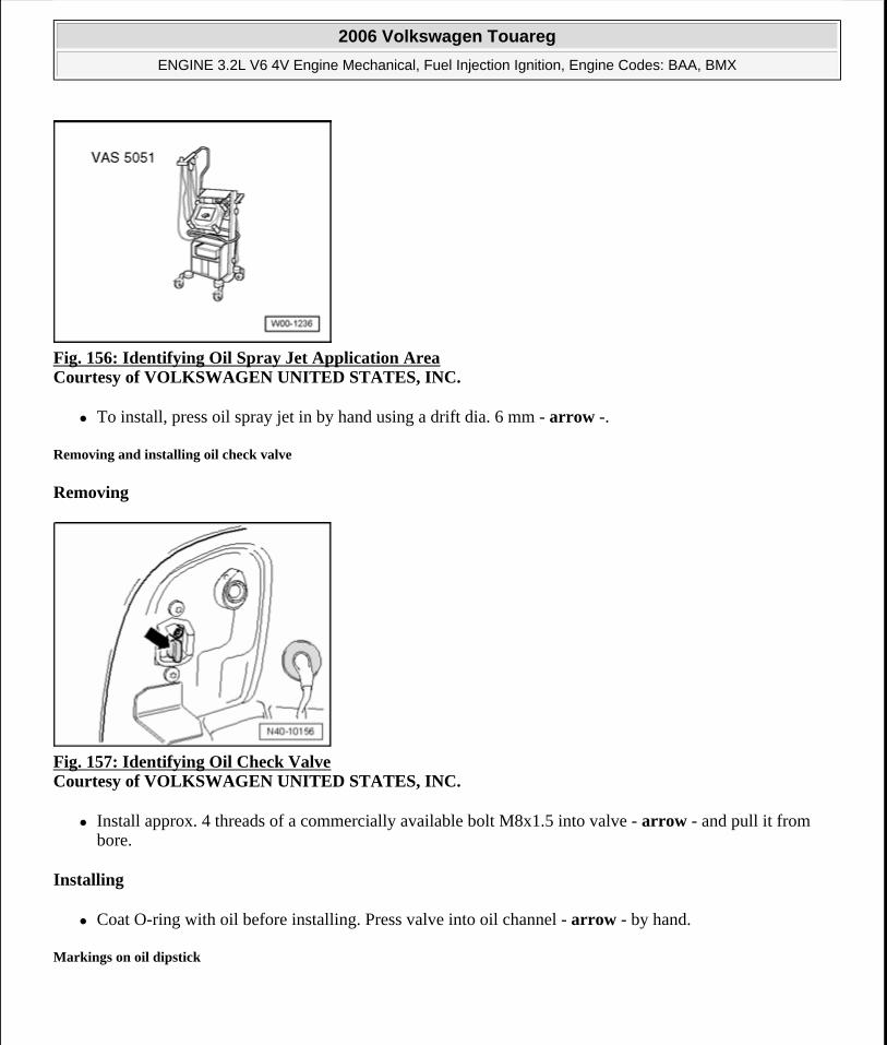
Fig. 156: Identifying Oil Spray Jet Application Area Courtesy of VOLKSWAGEN UNITED STATES, INC.
To install, press oil spray jet in by hand using a drift dia. 6 mm - arrow -.
Removing and installing oil check valve
Removing
Fig. 157: Identifying Oil Check Valve Courtesy of VOLKSWAGEN UNITED STATES, INC.
Install approx. 4 threads of a commercially available bolt M8x1.5 into valve - arrow - and pull it from bore.
Installing
Coat O-ring with oil before installing. Press valve into oil channel - arrow - by hand.
Markings on oil dipstick
2006 Volkswagen Touareg
ENGINE 3.2L V6 4V Engine Mechanical, Fuel Injection Ignition, Engine Codes: BAA, BMX
Microsoft
Sunday, September 20, 2009 9:14:18 AM Page 136 © 2005 Mitchell Repair Information Company, LLC.
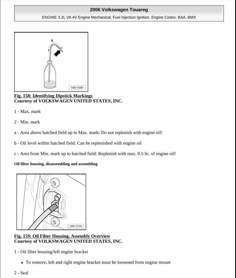
Fig. 158: Identifying Dipstick Markings Courtesy of VOLKSWAGEN UNITED STATES, INC.
1 - Max. mark
2 - Min. mark
a - Area above hatched field up to Max. mark: Do not replenish with engine oil!
b - Oil level within hatched field: Can be replenished with engine oil
c - Area from Min. mark up to hatched field: Replenish with max. 0.5 ltr. of engine oil!
Oil filter housing, disassembling and assembling
Fig. 159: Oil Filter Housing, Assembly Overview Courtesy of VOLKSWAGEN UNITED STATES, INC.
1 - Oil filter housing/left engine bracket
To remove, left and right engine bracket must be loosened from engine mount
2 - Seal
2006 Volkswagen Touareg
ENGINE 3.2L V6 4V Engine Mechanical, Fuel Injection Ignition, Engine Codes: BAA, BMX
Microsoft
Sunday, September 20, 2009 9:14:18 AM Page 137 © 2005 Mitchell Repair Information Company, LLC.
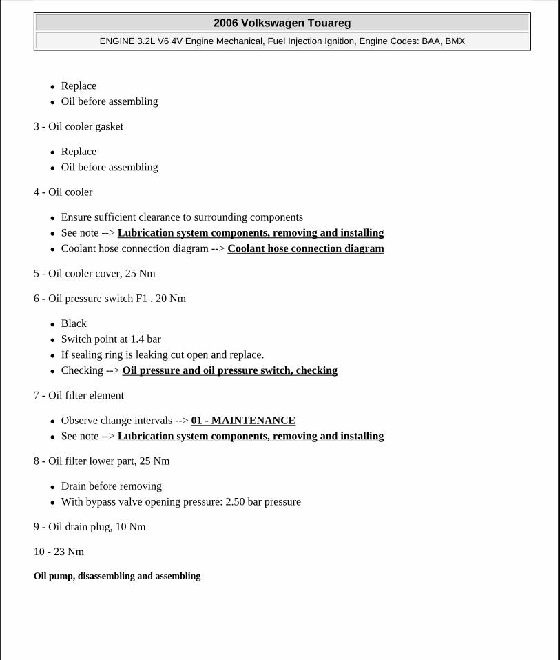
Replace
Oil before assembling
3 - Oil cooler gasket
Replace
Oil before assembling
4 - Oil cooler
Ensure sufficient clearance to surrounding components
See note --> Lubrication system components, removing and installing
Coolant hose connection diagram --> Coolant hose connection diagram
5 - Oil cooler cover, 25 Nm
6 - Oil pressure switch F1 , 20 Nm
Black
Switch point at 1.4 bar
If sealing ring is leaking cut open and replace.
Checking --> Oil pressure and oil pressure switch, checking
7 - Oil filter element
Observe change intervals --> 01 - MAINTENANCE
See note --> Lubrication system components, removing and installing
8 - Oil filter lower part, 25 Nm
Drain before removing
With bypass valve opening pressure: 2.50 bar pressure
9 - Oil drain plug, 10 Nm
10 - 23 Nm
Oil pump, disassembling and assembling
2006 Volkswagen Touareg
ENGINE 3.2L V6 4V Engine Mechanical, Fuel Injection Ignition, Engine Codes: BAA, BMX
Microsoft
Sunday, September 20, 2009 9:14:18 AM Page 138 © 2005 Mitchell Repair Information Company, LLC.
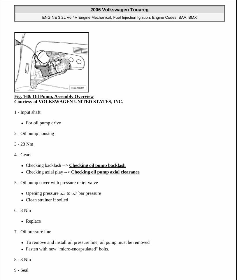
Fig. 160: Oil Pump, Assembly Overview Courtesy of VOLKSWAGEN UNITED STATES, INC.
1 - Input shaft
For oil pump drive
2 - Oil pump housing
3 - 23 Nm
4 - Gears
Checking backlash --> Checking oil pump backlash
Checking axial play --> Checking oil pump axial clearance
5 - Oil pump cover with pressure relief valve
Opening pressure 5.3 to 5.7 bar pressure
Clean strainer if soiled
6 - 8 Nm
Replace
7 - Oil pressure line
To remove and install oil pressure line, oil pump must be removed
Fasten with new "micro-encapsulated" bolts.
8 - 8 Nm
9 - Seal
2006 Volkswagen Touareg
ENGINE 3.2L V6 4V Engine Mechanical, Fuel Injection Ignition, Engine Codes: BAA, BMX
Microsoft
Sunday, September 20, 2009 9:14:18 AM Page 139 © 2005 Mitchell Repair Information Company, LLC.
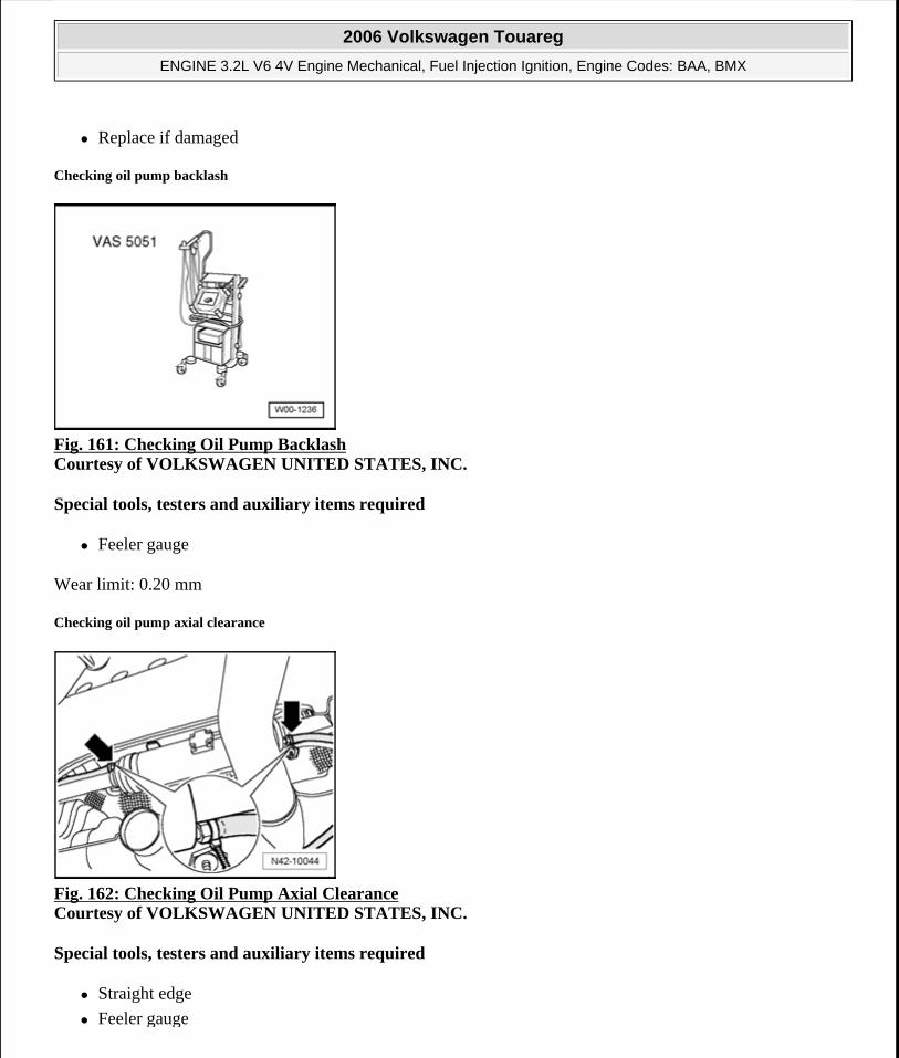
Replace if damaged
Checking oil pump backlash
Fig. 161: Checking Oil Pump Backlash Courtesy of VOLKSWAGEN UNITED STATES, INC.
Special tools, testers and auxiliary items required
Feeler gauge
Wear limit: 0.20 mm
Checking oil pump axial clearance
Fig. 162: Checking Oil Pump Axial Clearance Courtesy of VOLKSWAGEN UNITED STATES, INC.
Special tools, testers and auxiliary items required
Straight edge
Feeler gauge
2006 Volkswagen Touareg
ENGINE 3.2L V6 4V Engine Mechanical, Fuel Injection Ignition, Engine Codes: BAA, BMX
Microsoft
Sunday, September 20, 2009 9:14:18 AM Page 140 © 2005 Mitchell Repair Information Company, LLC.
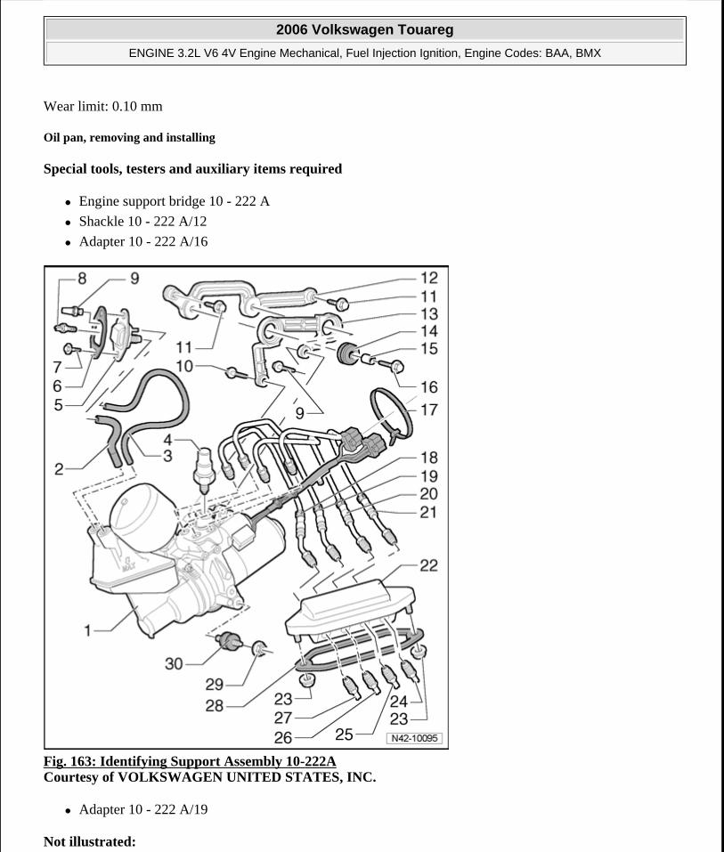
Wear limit: 0.10 mm
Oil pan, removing and installing
Special tools, testers and auxiliary items required
Engine support bridge 10 - 222 A
Shackle 10 - 222 A/12
Adapter 10 - 222 A/16
Fig. 163: Identifying Support Assembly 10-222A Courtesy of VOLKSWAGEN UNITED STATES, INC.
Adapter 10 - 222 A/19
Not illustrated:
2006 Volkswagen Touareg
ENGINE 3.2L V6 4V Engine Mechanical, Fuel Injection Ignition, Engine Codes: BAA, BMX
Microsoft
Sunday, September 20, 2009 9:14:18 AM Page 141 © 2005 Mitchell Repair Information Company, LLC.
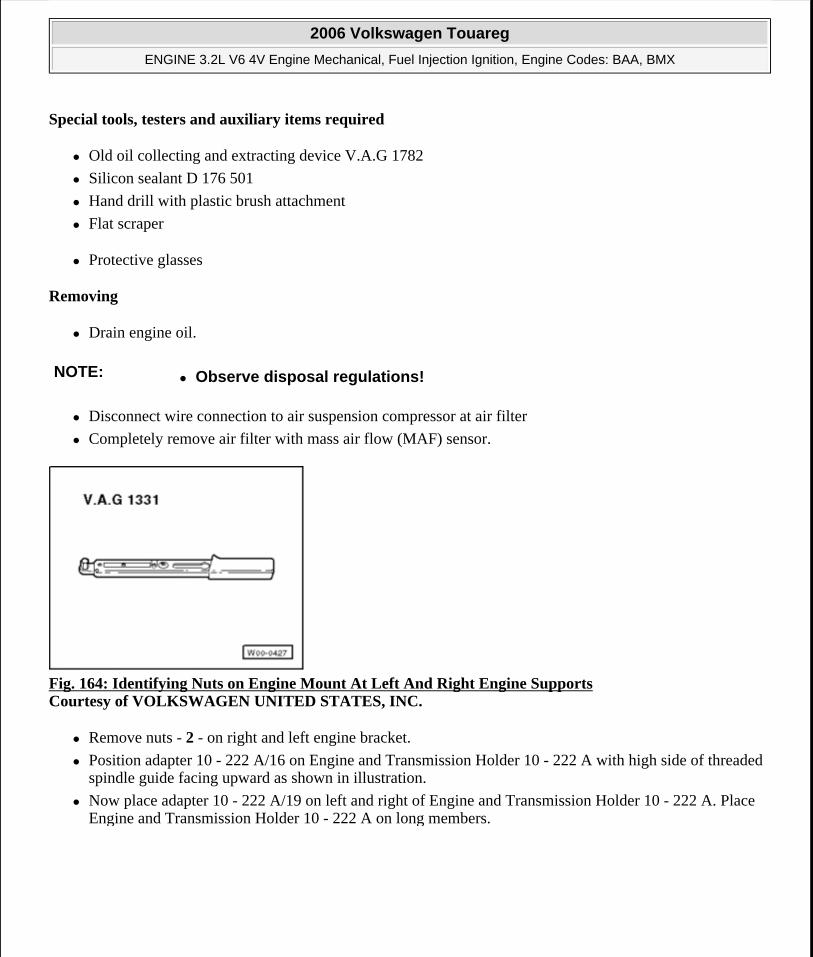
Special tools, testers and auxiliary items required
Old oil collecting and extracting device V.A.G 1782
Silicon sealant D 176 501
Hand drill with plastic brush attachment
Flat scraper
Protective glasses
Removing
Drain engine oil.
Disconnect wire connection to air suspension compressor at air filter
Completely remove air filter with mass air flow (MAF) sensor.
Fig. 164: Identifying Nuts on Engine Mount At Left And Right Engine Supports Courtesy of VOLKSWAGEN UNITED STATES, INC.
Remove nuts - 2 - on right and left engine bracket.
Position adapter 10 - 222 A/16 on Engine and Transmission Holder 10 - 222 A with high side of threaded spindle guide facing upward as shown in illustration.
Now place adapter 10 - 222 A/19 on left and right of Engine and Transmission Holder 10 - 222 A. Place Engine and Transmission Holder 10 - 222 A on long members.
NOTE: Observe disposal regulations!
2006 Volkswagen Touareg
ENGINE 3.2L V6 4V Engine Mechanical, Fuel Injection Ignition, Engine Codes: BAA, BMX
Microsoft
Sunday, September 20, 2009 9:14:18 AM Page 142 © 2005 Mitchell Repair Information Company, LLC.
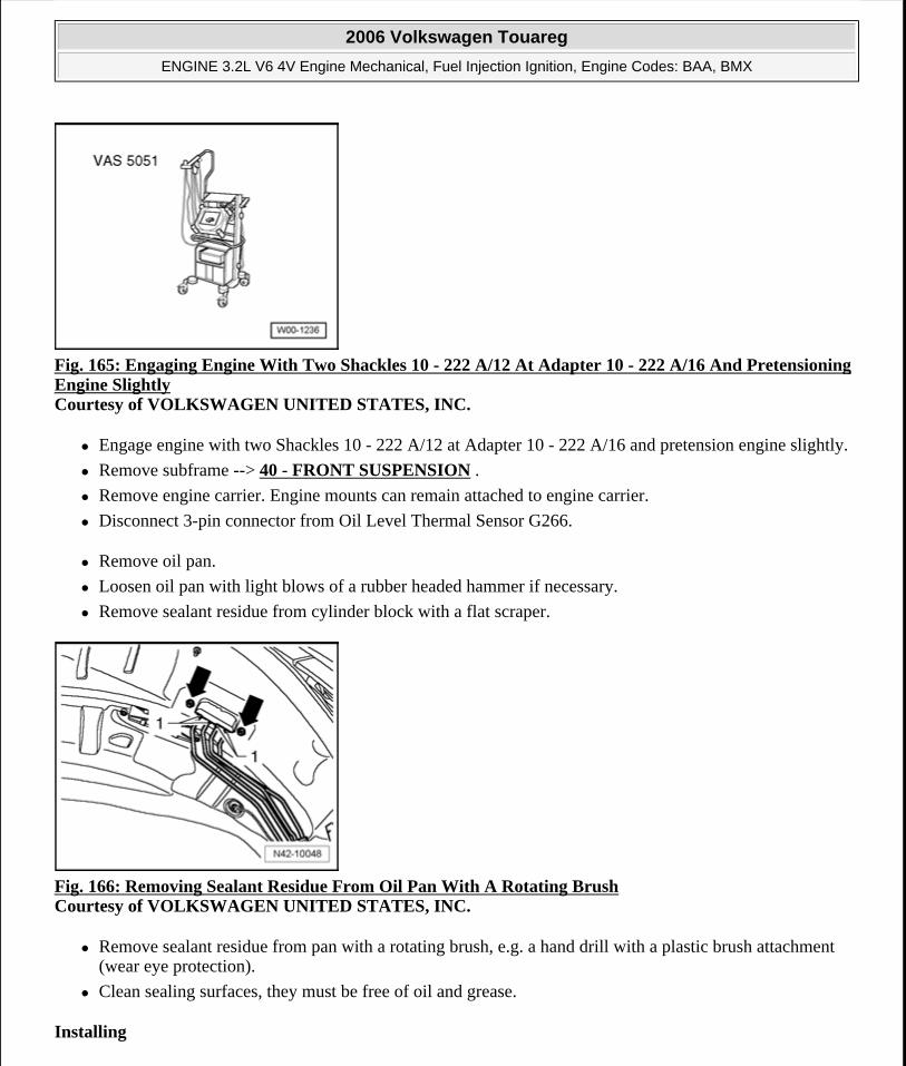
Fig. 165: Engaging Engine With Two Shackles 10 - 222 A/12 At Adapter 10 - 222 A/16 And Pretensioning Engine Slightly Courtesy of VOLKSWAGEN UNITED STATES, INC.
Engage engine with two Shackles 10 - 222 A/12 at Adapter 10 - 222 A/16 and pretension engine slightly.
Remove subframe --> 40 - FRONT SUSPENSION .
Remove engine carrier. Engine mounts can remain attached to engine carrier.
Disconnect 3-pin connector from Oil Level Thermal Sensor G266.
Remove oil pan.
Loosen oil pan with light blows of a rubber headed hammer if necessary.
Remove sealant residue from cylinder block with a flat scraper.
Fig. 166: Removing Sealant Residue From Oil Pan With A Rotating Brush Courtesy of VOLKSWAGEN UNITED STATES, INC.
Remove sealant residue from pan with a rotating brush, e.g. a hand drill with a plastic brush attachment (wear eye protection).
Clean sealing surfaces, they must be free of oil and grease.
Installing
2006 Volkswagen Touareg
ENGINE 3.2L V6 4V Engine Mechanical, Fuel Injection Ignition, Engine Codes: BAA, BMX
Microsoft
Sunday, September 20, 2009 9:14:18 AM Page 143 © 2005 Mitchell Repair Information Company, LLC.
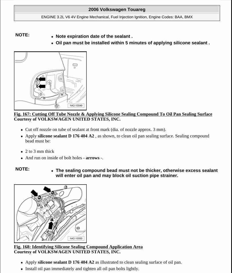
Fig. 167: Cutting Off Tube Nozzle & Applying Silicone Sealing Compound To Oil Pan Sealing Surface Courtesy of VOLKSWAGEN UNITED STATES, INC.
Cut off nozzle on tube of sealant at front mark (dia. of nozzle approx. 3 mm).
Apply silicone sealant D 176 404 A2 , as shown, to clean oil pan sealing surface. Sealing compound bead must be:
2 to 3 mm thick
And run on inside of bolt holes - arrows -.
Fig. 168: Identifying Silicone Sealing Compound Application Area Courtesy of VOLKSWAGEN UNITED STATES, INC.
Apply silicone sealant D 176 404 A2 as illustrated to clean sealing surface of oil pan.
Install oil pan immediately and tighten all oil pan bolts lightly.
NOTE: Note expiration date of the sealant .
Oil pan must be installed within 5 minutes of applying silicone sealant .
NOTE: The sealing compound bead must not be thicker, otherwise excess sealantwill enter oil pan and may block oil suction pipe strainer.
2006 Volkswagen Touareg
ENGINE 3.2L V6 4V Engine Mechanical, Fuel Injection Ignition, Engine Codes: BAA, BMX
Microsoft
Sunday, September 20, 2009 9:14:18 AM Page 144 © 2005 Mitchell Repair Information Company, LLC.
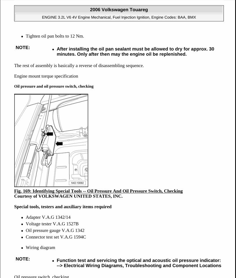
Tighten oil pan bolts to 12 Nm.
The rest of assembly is basically a reverse of disassembling sequence.
Engine mount torque specification
Oil pressure and oil pressure switch, checking
Fig. 169: Identifying Special Tools -- Oil Pressure And Oil Pressure Switch, Checking Courtesy of VOLKSWAGEN UNITED STATES, INC.
Special tools, testers and auxiliary items required
Adapter V.A.G 1342/14
Voltage tester V.A.G 1527B
Oil pressure gauge V.A.G 1342
Connector test set V.A.G 1594C
Wiring diagram
Oil pressure switch, checking
NOTE: After installing the oil pan sealant must be allowed to dry for approx. 30 minutes. Only after then may the engine oil be replenished.
NOTE: Function test and servicing the optical and acoustic oil pressure indicator: --> Electrical Wiring Diagrams, Troubleshooting and Component Locations
2006 Volkswagen Touareg
ENGINE 3.2L V6 4V Engine Mechanical, Fuel Injection Ignition, Engine Codes: BAA, BMX
Microsoft
Sunday, September 20, 2009 9:14:18 AM Page 145 © 2005 Mitchell Repair Information Company, LLC.
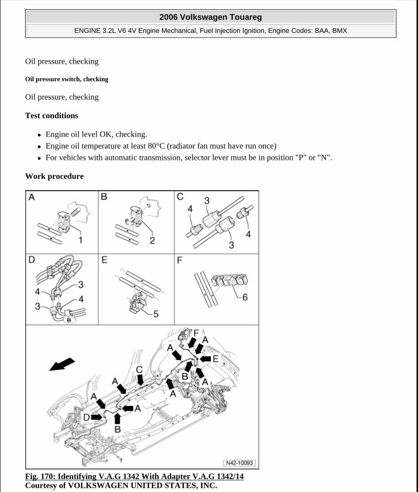
Oil pressure, checking
Oil pressure switch, checking
Oil pressure, checking
Test conditions
Engine oil level OK, checking.
Engine oil temperature at least 80°C (radiator fan must have run once)
For vehicles with automatic transmission, selector lever must be in position "P" or "N".
Work procedure
Fig. 170: Identifying V.A.G 1342 With Adapter V.A.G 1342/14 Courtesy of VOLKSWAGEN UNITED STATES, INC.
2006 Volkswagen Touareg
ENGINE 3.2L V6 4V Engine Mechanical, Fuel Injection Ignition, Engine Codes: BAA, BMX
Microsoft
Sunday, September 20, 2009 9:14:18 AM Page 146 © 2005 Mitchell Repair Information Company, LLC.
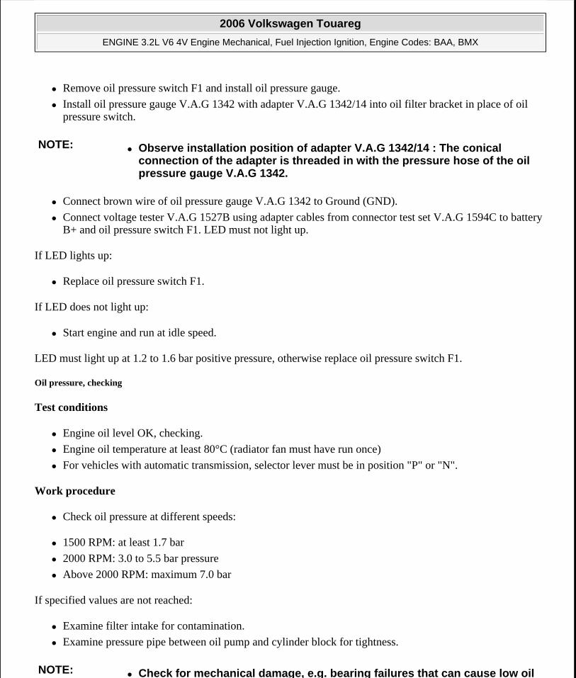
Remove oil pressure switch F1 and install oil pressure gauge.
Install oil pressure gauge V.A.G 1342 with adapter V.A.G 1342/14 into oil filter bracket in place of oil pressure switch.
Connect brown wire of oil pressure gauge V.A.G 1342 to Ground (GND).
Connect voltage tester V.A.G 1527B using adapter cables from connector test set V.A.G 1594C to battery B+ and oil pressure switch F1. LED must not light up.
If LED lights up:
Replace oil pressure switch F1.
If LED does not light up:
Start engine and run at idle speed.
LED must light up at 1.2 to 1.6 bar positive pressure, otherwise replace oil pressure switch F1.
Oil pressure, checking
Test conditions
Engine oil level OK, checking.
Engine oil temperature at least 80°C (radiator fan must have run once)
For vehicles with automatic transmission, selector lever must be in position "P" or "N".
Work procedure
Check oil pressure at different speeds:
1500 RPM: at least 1.7 bar
2000 RPM: 3.0 to 5.5 bar pressure
Above 2000 RPM: maximum 7.0 bar
If specified values are not reached:
Examine filter intake for contamination.
Examine pressure pipe between oil pump and cylinder block for tightness.
NOTE: Observe installation position of adapter V.A.G 1342/14 : The conical connection of the adapter is threaded in with the pressure hose of the oil pressure gauge V.A.G 1342.
NOTE: Check for mechanical damage, e.g. bearing failures that can cause low oil
2006 Volkswagen Touareg
ENGINE 3.2L V6 4V Engine Mechanical, Fuel Injection Ignition, Engine Codes: BAA, BMX
Microsoft
Sunday, September 20, 2009 9:14:18 AM Page 147 © 2005 Mitchell Repair Information Company, LLC.
If a malfunction is found despite insufficient oil pressure:
Replace oil pump --> Oil pump, disassembling and assembling
The oil pressure must not exceed 7.0 bar.
If 7.0 bar is exceeded:
Check oil channels.
Possibly/oil pressure relief valve in oil pump is plugged.
Replace oil pump.
19 - ENGINE - COOLING SYSTEM
COOLING SYSTEM COMPONENTS, REMOVING AND INSTALLING
Cooling system components, removing and installing
pressure.
CAUTION: Hot steam may escape when opening expansion tank. Wear protective goggles and protective clothing to prevent damage to eyes and scalding. Cover cap with a rag and open carefully.
CAUTION: When doing any repair work, especially in the engine compartment, pay attention to the following due to clearance issues:
Route all the various lines (e.g. for fuel, hydraulics, EVAP system, coolant, refrigerant, brake fluid and vacuum lines and hoses) and electrical wiring so that the original positions are restored.
Ensure sufficient clearance to all moving or hot components.
NOTE: Hoses are secured with spring-type clips. In cases of repair only use spring-type clips.
2006 Volkswagen Touareg
ENGINE 3.2L V6 4V Engine Mechanical, Fuel Injection Ignition, Engine Codes: BAA, BMX
Microsoft
Sunday, September 20, 2009 9:14:18 AM Page 148 © 2005 Mitchell Repair Information Company, LLC.
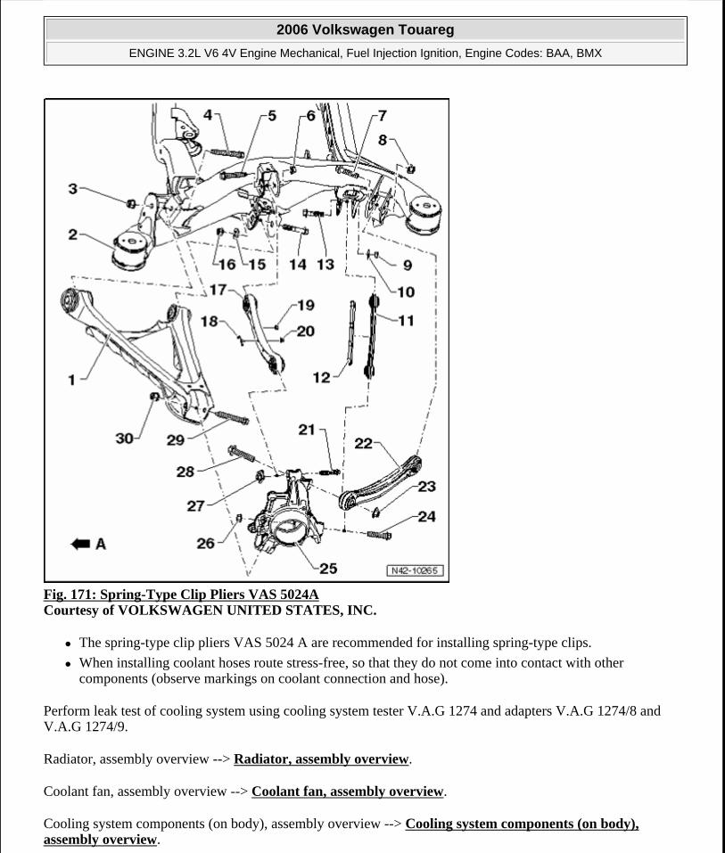
Fig. 171: Spring-Type Clip Pliers VAS 5024A Courtesy of VOLKSWAGEN UNITED STATES, INC.
The spring-type clip pliers VAS 5024 A are recommended for installing spring-type clips.
When installing coolant hoses route stress-free, so that they do not come into contact with other components (observe markings on coolant connection and hose).
Perform leak test of cooling system using cooling system tester V.A.G 1274 and adapters V.A.G 1274/8 and V.A.G 1274/9.
Radiator, assembly overview --> Radiator, assembly overview.
Coolant fan, assembly overview --> Coolant fan, assembly overview.
Cooling system components (on body), assembly overview --> Cooling system components (on body), assembly overview.
2006 Volkswagen Touareg
ENGINE 3.2L V6 4V Engine Mechanical, Fuel Injection Ignition, Engine Codes: BAA, BMX
Microsoft
Sunday, September 20, 2009 9:14:18 AM Page 149 © 2005 Mitchell Repair Information Company, LLC.
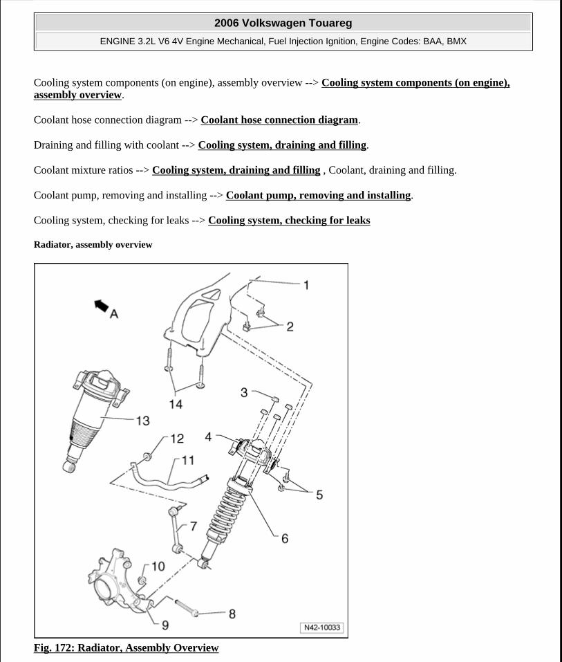
Cooling system components (on engine), assembly overview --> Cooling system components (on engine), assembly overview.
Coolant hose connection diagram --> Coolant hose connection diagram.
Draining and filling with coolant --> Cooling system, draining and filling.
Coolant mixture ratios --> Cooling system, draining and filling , Coolant, draining and filling.
Coolant pump, removing and installing --> Coolant pump, removing and installing.
Cooling system, checking for leaks --> Cooling system, checking for leaks
Radiator, assembly overview
Fig. 172: Radiator, Assembly Overview
2006 Volkswagen Touareg
ENGINE 3.2L V6 4V Engine Mechanical, Fuel Injection Ignition, Engine Codes: BAA, BMX
Microsoft
Sunday, September 20, 2009 9:14:18 AM Page 150 © 2005 Mitchell Repair Information Company, LLC.
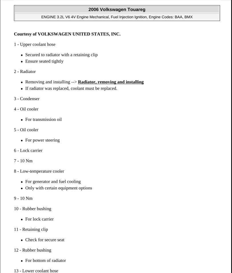
Courtesy of VOLKSWAGEN UNITED STATES, INC.
1 - Upper coolant hose
Secured to radiator with a retaining clip
Ensure seated tightly
2 - Radiator
Removing and installing --> Radiator, removing and installing
If radiator was replaced, coolant must be replaced.
3 - Condenser
4 - Oil cooler
For transmission oil
5 - Oil cooler
For power steering
6 - Lock carrier
7 - 10 Nm
8 - Low-temperature cooler
For generator and fuel cooling
Only with certain equipment options
9 - 10 Nm
10 - Rubber bushing
For lock carrier
11 - Retaining clip
Check for secure seat
12 - Rubber bushing
For bottom of radiator
13 - Lower coolant hose
2006 Volkswagen Touareg
ENGINE 3.2L V6 4V Engine Mechanical, Fuel Injection Ignition, Engine Codes: BAA, BMX
Microsoft
Sunday, September 20, 2009 9:14:18 AM Page 151 © 2005 Mitchell Repair Information Company, LLC.
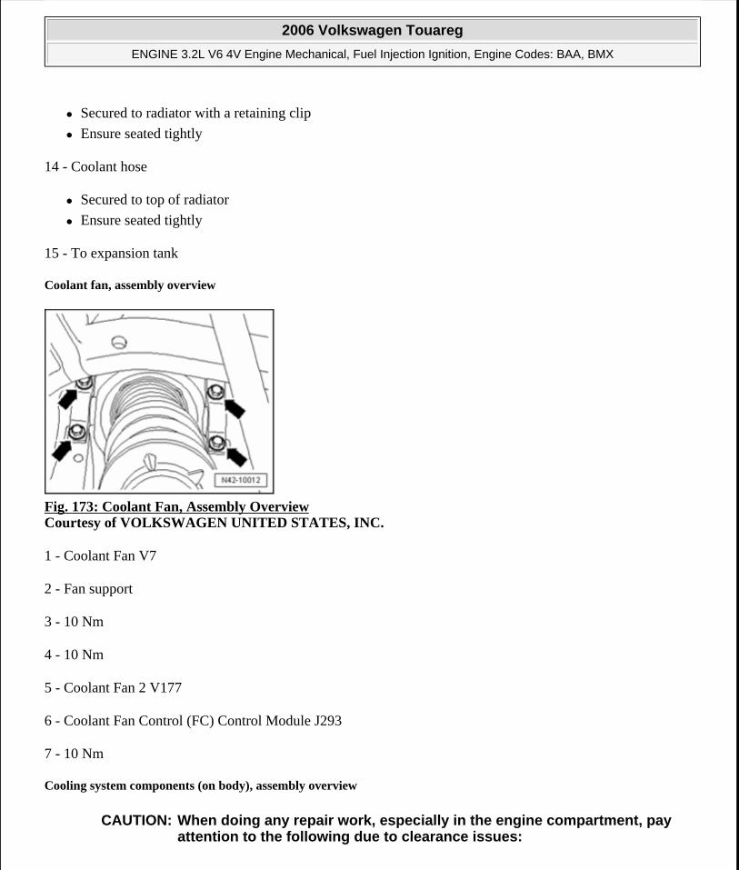
Secured to radiator with a retaining clip
Ensure seated tightly
14 - Coolant hose
Secured to top of radiator
Ensure seated tightly
15 - To expansion tank
Coolant fan, assembly overview
Fig. 173: Coolant Fan, Assembly Overview Courtesy of VOLKSWAGEN UNITED STATES, INC.
1 - Coolant Fan V7
2 - Fan support
3 - 10 Nm
4 - 10 Nm
5 - Coolant Fan 2 V177
6 - Coolant Fan Control (FC) Control Module J293
7 - 10 Nm
Cooling system components (on body), assembly overview
CAUTION: When doing any repair work, especially in the engine compartment, pay attention to the following due to clearance issues:
2006 Volkswagen Touareg
ENGINE 3.2L V6 4V Engine Mechanical, Fuel Injection Ignition, Engine Codes: BAA, BMX
Microsoft
Sunday, September 20, 2009 9:14:18 AM Page 152 © 2005 Mitchell Repair Information Company, LLC.
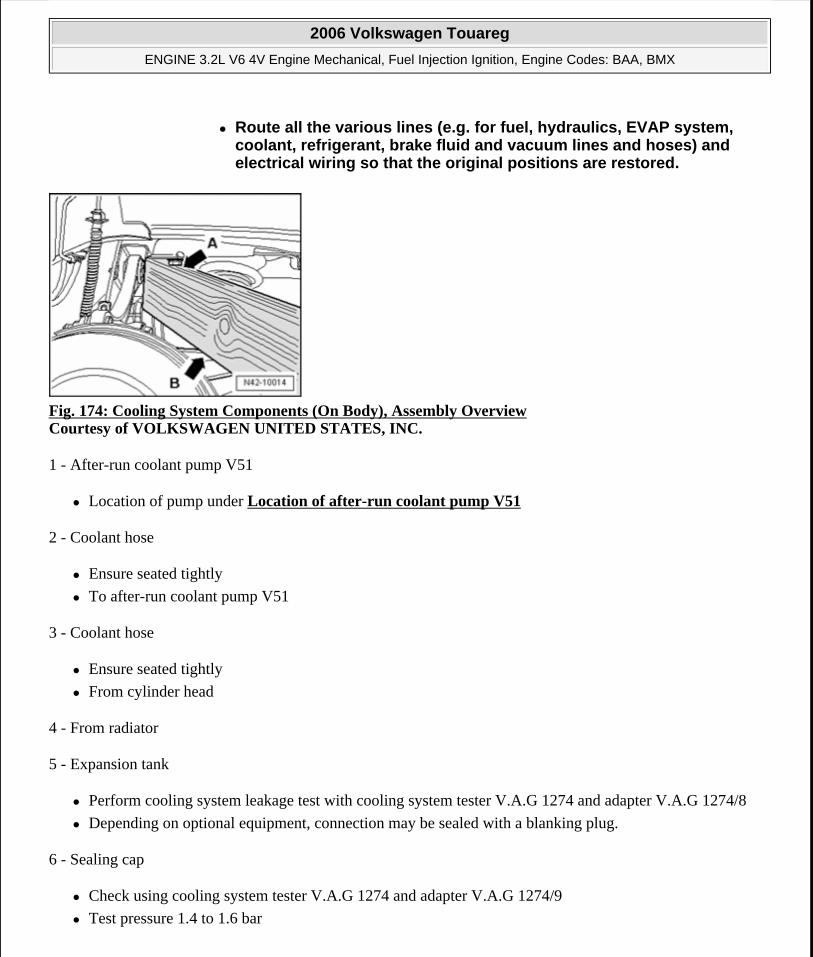
Fig. 174: Cooling System Components (On Body), Assembly Overview Courtesy of VOLKSWAGEN UNITED STATES, INC.
1 - After-run coolant pump V51
Location of pump under Location of after-run coolant pump V51
2 - Coolant hose
Ensure seated tightly
To after-run coolant pump V51
3 - Coolant hose
Ensure seated tightly
From cylinder head
4 - From radiator
5 - Expansion tank
Perform cooling system leakage test with cooling system tester V.A.G 1274 and adapter V.A.G 1274/8
Depending on optional equipment, connection may be sealed with a blanking plug.
6 - Sealing cap
Check using cooling system tester V.A.G 1274 and adapter V.A.G 1274/9
Test pressure 1.4 to 1.6 bar
Route all the various lines (e.g. for fuel, hydraulics, EVAP system, coolant, refrigerant, brake fluid and vacuum lines and hoses) and electrical wiring so that the original positions are restored.
2006 Volkswagen Touareg
ENGINE 3.2L V6 4V Engine Mechanical, Fuel Injection Ignition, Engine Codes: BAA, BMX
Microsoft
Sunday, September 20, 2009 9:14:18 AM Page 153 © 2005 Mitchell Repair Information Company, LLC.
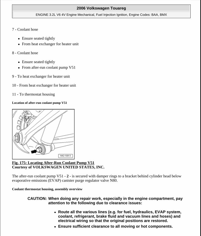
7 - Coolant hose
Ensure seated tightly
From heat exchanger for heater unit
8 - Coolant hose
Ensure seated tightly
From after-run coolant pump V51
9 - To heat exchanger for heater unit
10 - From heat exchanger for heater unit
11 - To thermostat housing
Location of after-run coolant pump V51
Fig. 175: Locating After-Run Coolant Pump V51 Courtesy of VOLKSWAGEN UNITED STATES, INC.
The after-run coolant pump V51 - 2 - is secured with damper rings to a bracket behind cylinder head below evaporative emissions (EVAP) canister purge regulator valve N80.
Coolant thermostat housing, assembly overview
CAUTION: When doing any repair work, especially in the engine compartment, pay attention to the following due to clearance issues:
Route all the various lines (e.g. for fuel, hydraulics, EVAP system, coolant, refrigerant, brake fluid and vacuum lines and hoses) and electrical wiring so that the original positions are restored.
Ensure sufficient clearance to all moving or hot components.
2006 Volkswagen Touareg
ENGINE 3.2L V6 4V Engine Mechanical, Fuel Injection Ignition, Engine Codes: BAA, BMX
Microsoft
Sunday, September 20, 2009 9:14:18 AM Page 154 © 2005 Mitchell Repair Information Company, LLC.
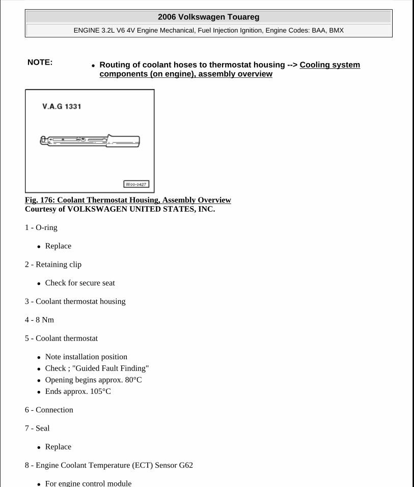
Fig. 176: Coolant Thermostat Housing, Assembly Overview Courtesy of VOLKSWAGEN UNITED STATES, INC.
1 - O-ring
Replace
2 - Retaining clip
Check for secure seat
3 - Coolant thermostat housing
4 - 8 Nm
5 - Coolant thermostat
Note installation position
Check ; "Guided Fault Finding"
Opening begins approx. 80°C
Ends approx. 105°C
6 - Connection
7 - Seal
Replace
8 - Engine Coolant Temperature (ECT) Sensor G62
For engine control module
NOTE: Routing of coolant hoses to thermostat housing --> Cooling system components (on engine), assembly overview
2006 Volkswagen Touareg
ENGINE 3.2L V6 4V Engine Mechanical, Fuel Injection Ignition, Engine Codes: BAA, BMX
Microsoft
Sunday, September 20, 2009 9:14:18 AM Page 155 © 2005 Mitchell Repair Information Company, LLC.
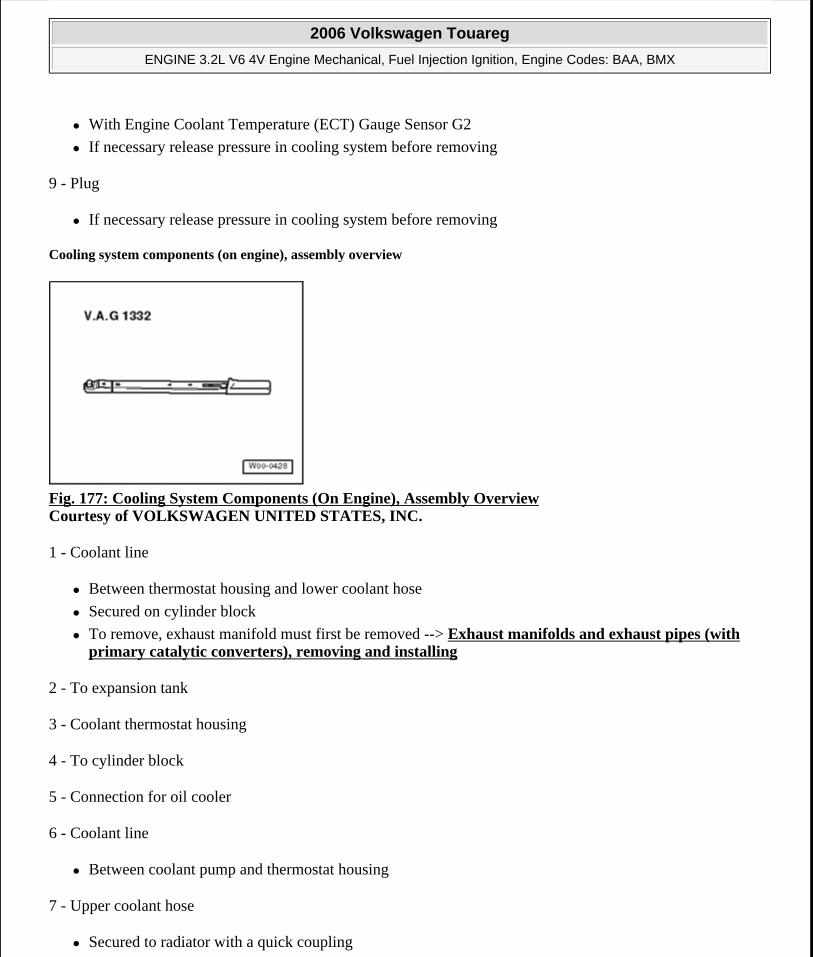
With Engine Coolant Temperature (ECT) Gauge Sensor G2
If necessary release pressure in cooling system before removing
9 - Plug
If necessary release pressure in cooling system before removing
Cooling system components (on engine), assembly overview
Fig. 177: Cooling System Components (On Engine), Assembly Overview Courtesy of VOLKSWAGEN UNITED STATES, INC.
1 - Coolant line
Between thermostat housing and lower coolant hose
Secured on cylinder block
To remove, exhaust manifold must first be removed --> Exhaust manifolds and exhaust pipes (with primary catalytic converters), removing and installing
2 - To expansion tank
3 - Coolant thermostat housing
4 - To cylinder block
5 - Connection for oil cooler
6 - Coolant line
Between coolant pump and thermostat housing
7 - Upper coolant hose
Secured to radiator with a quick coupling
2006 Volkswagen Touareg
ENGINE 3.2L V6 4V Engine Mechanical, Fuel Injection Ignition, Engine Codes: BAA, BMX
Microsoft
Sunday, September 20, 2009 9:14:18 AM Page 156 © 2005 Mitchell Repair Information Company, LLC.
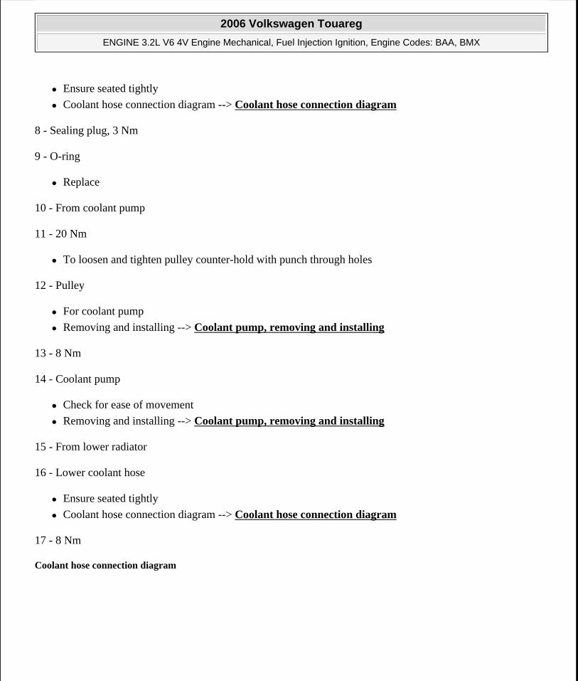
Ensure seated tightly
Coolant hose connection diagram --> Coolant hose connection diagram
8 - Sealing plug, 3 Nm
9 - O-ring
Replace
10 - From coolant pump
11 - 20 Nm
To loosen and tighten pulley counter-hold with punch through holes
12 - Pulley
For coolant pump
Removing and installing --> Coolant pump, removing and installing
13 - 8 Nm
14 - Coolant pump
Check for ease of movement
Removing and installing --> Coolant pump, removing and installing
15 - From lower radiator
16 - Lower coolant hose
Ensure seated tightly
Coolant hose connection diagram --> Coolant hose connection diagram
17 - 8 Nm
Coolant hose connection diagram
2006 Volkswagen Touareg
ENGINE 3.2L V6 4V Engine Mechanical, Fuel Injection Ignition, Engine Codes: BAA, BMX
Microsoft
Sunday, September 20, 2009 9:14:18 AM Page 157 © 2005 Mitchell Repair Information Company, LLC.
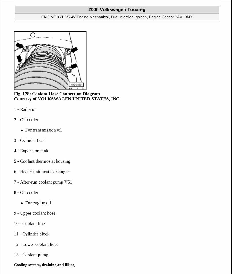
Fig. 178: Coolant Hose Connection Diagram Courtesy of VOLKSWAGEN UNITED STATES, INC.
1 - Radiator
2 - Oil cooler
For transmission oil
3 - Cylinder head
4 - Expansion tank
5 - Coolant thermostat housing
6 - Heater unit heat exchanger
7 - After-run coolant pump V51
8 - Oil cooler
For engine oil
9 - Upper coolant hose
10 - Coolant line
11 - Cylinder block
12 - Lower coolant hose
13 - Coolant pump
Cooling system, draining and filling
2006 Volkswagen Touareg
ENGINE 3.2L V6 4V Engine Mechanical, Fuel Injection Ignition, Engine Codes: BAA, BMX
Microsoft
Sunday, September 20, 2009 9:14:18 AM Page 158 © 2005 Mitchell Repair Information Company, LLC.
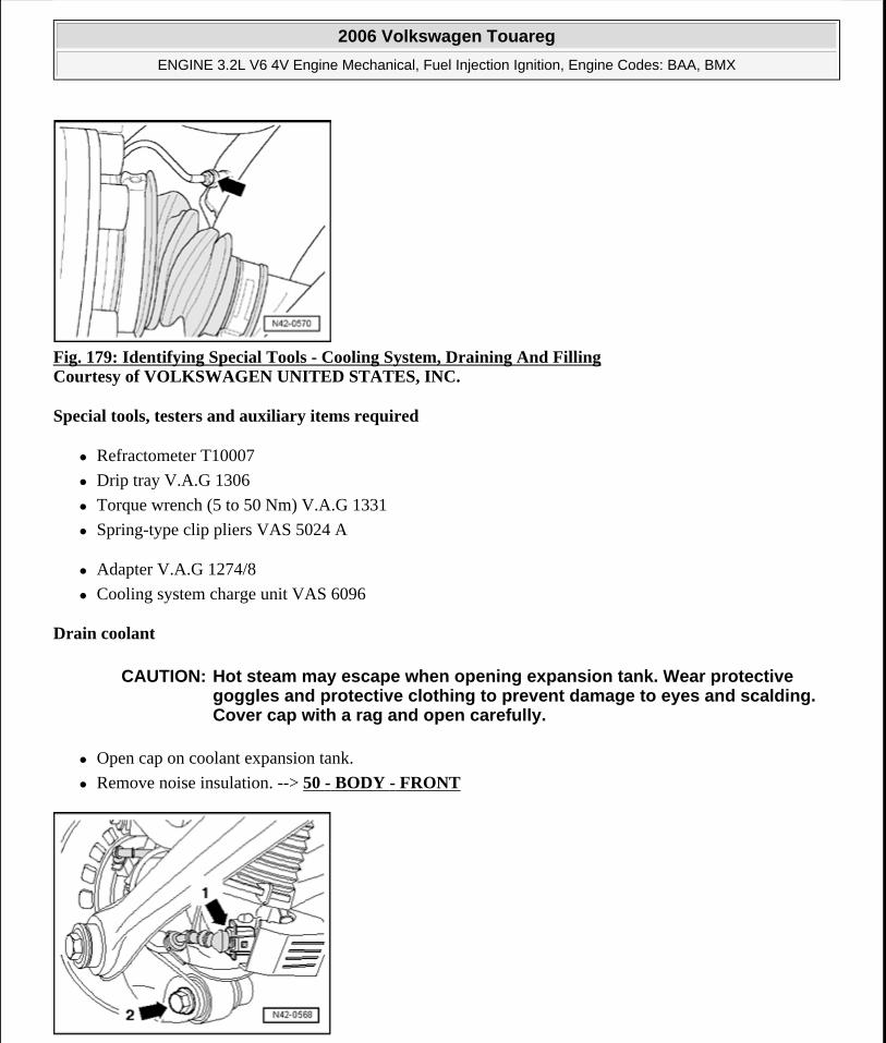
Fig. 179: Identifying Special Tools - Cooling System, Draining And Filling Courtesy of VOLKSWAGEN UNITED STATES, INC.
Special tools, testers and auxiliary items required
Refractometer T10007
Drip tray V.A.G 1306
Torque wrench (5 to 50 Nm) V.A.G 1331
Spring-type clip pliers VAS 5024 A
Adapter V.A.G 1274/8
Cooling system charge unit VAS 6096
Drain coolant
Open cap on coolant expansion tank.
Remove noise insulation. --> 50 - BODY - FRONT
CAUTION: Hot steam may escape when opening expansion tank. Wear protective goggles and protective clothing to prevent damage to eyes and scalding. Cover cap with a rag and open carefully.
2006 Volkswagen Touareg
ENGINE 3.2L V6 4V Engine Mechanical, Fuel Injection Ignition, Engine Codes: BAA, BMX
Microsoft
Sunday, September 20, 2009 9:14:18 AM Page 159 © 2005 Mitchell Repair Information Company, LLC.
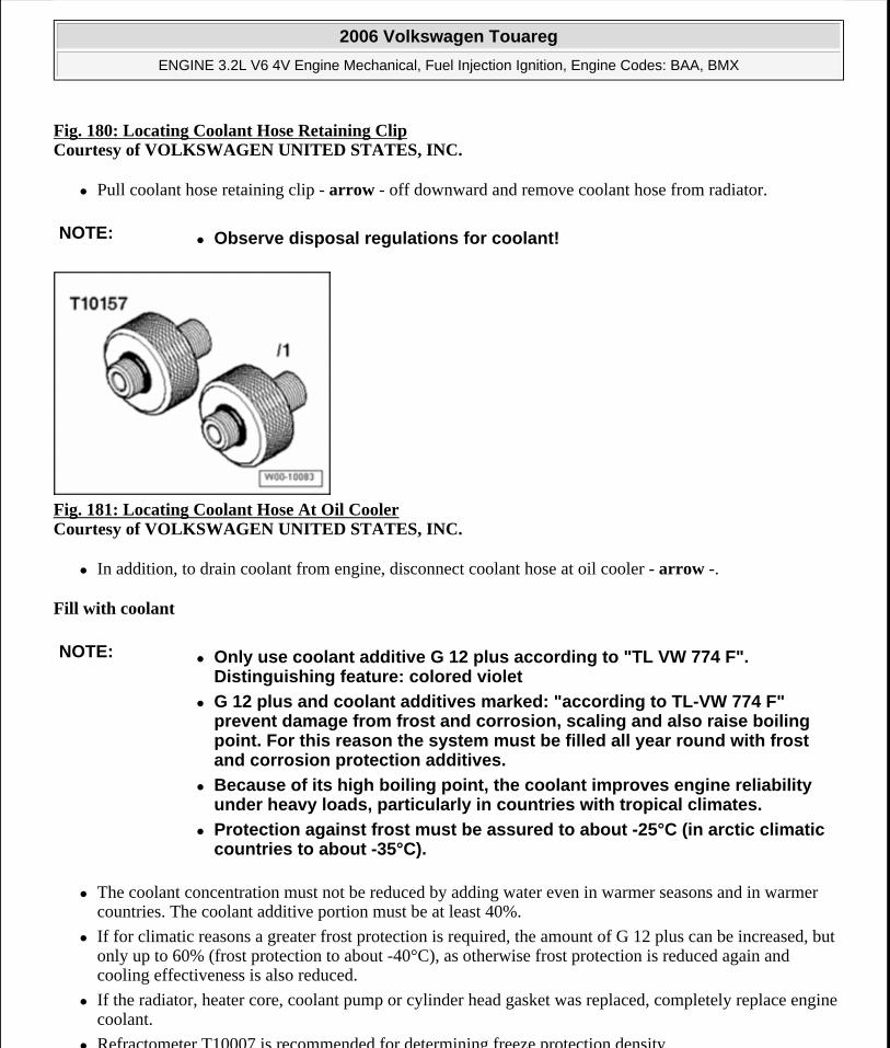
Fig. 180: Locating Coolant Hose Retaining ClipCourtesy of VOLKSWAGEN UNITED STATES, INC.
Pull coolant hose retaining clip - arrow - off downward and remove coolant hose from radiator.
Fig. 181: Locating Coolant Hose At Oil Cooler Courtesy of VOLKSWAGEN UNITED STATES, INC.
In addition, to drain coolant from engine, disconnect coolant hose at oil cooler - arrow -.
Fill with coolant
The coolant concentration must not be reduced by adding water even in warmer seasons and in warmer countries. The coolant additive portion must be at least 40%.
If for climatic reasons a greater frost protection is required, the amount of G 12 plus can be increased, but only up to 60% (frost protection to about -40°C), as otherwise frost protection is reduced again and cooling effectiveness is also reduced.
If the radiator, heater core, coolant pump or cylinder head gasket was replaced, completely replace engine coolant.
Refractometer T10007 is recommended for determining freeze protection density.
NOTE: Observe disposal regulations for coolant!
NOTE: Only use coolant additive G 12 plus according to "TL VW 774 F". Distinguishing feature: colored violet
G 12 plus and coolant additives marked: "according to TL-VW 774 F" prevent damage from frost and corrosion, scaling and also raise boiling point. For this reason the system must be filled all year round with frost and corrosion protection additives.
Because of its high boiling point, the coolant improves engine reliability under heavy loads, particularly in countries with tropical climates.
Protection against frost must be assured to about -25°C (in arctic climatic countries to about -35°C).
2006 Volkswagen Touareg
ENGINE 3.2L V6 4V Engine Mechanical, Fuel Injection Ignition, Engine Codes: BAA, BMX
Microsoft
Sunday, September 20, 2009 9:14:18 AM Page 160 © 2005 Mitchell Repair Information Company, LLC.
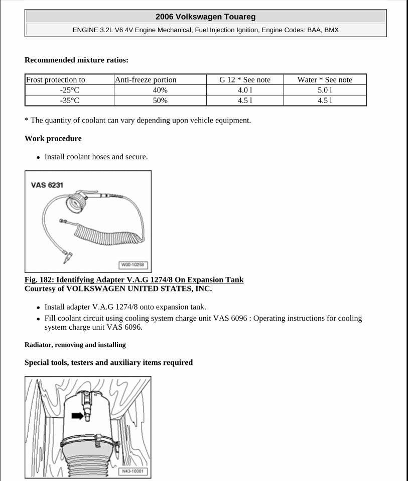
Recommended mixture ratios:
* The quantity of coolant can vary depending upon vehicle equipment.
Work procedure
Install coolant hoses and secure.
Fig. 182: Identifying Adapter V.A.G 1274/8 On Expansion Tank Courtesy of VOLKSWAGEN UNITED STATES, INC.
Install adapter V.A.G 1274/8 onto expansion tank.
Fill coolant circuit using cooling system charge unit VAS 6096 : Operating instructions for cooling system charge unit VAS 6096.
Radiator, removing and installing
Special tools, testers and auxiliary items required
Frost protection to Anti-freeze portion G 12 * See note Water * See note-25°C 40% 4.0 l 5.0 l-35°C 50% 4.5 l 4.5 l
2006 Volkswagen Touareg
ENGINE 3.2L V6 4V Engine Mechanical, Fuel Injection Ignition, Engine Codes: BAA, BMX
Microsoft
Sunday, September 20, 2009 9:14:18 AM Page 161 © 2005 Mitchell Repair Information Company, LLC.
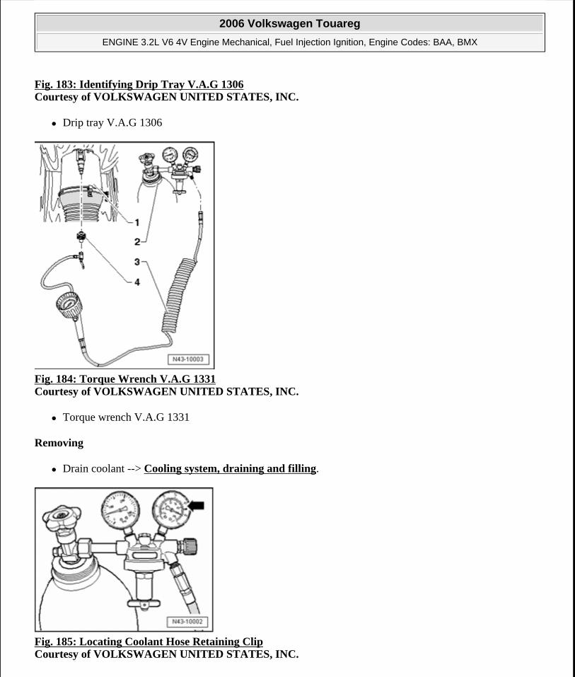
Fig. 183: Identifying Drip Tray V.A.G 1306Courtesy of VOLKSWAGEN UNITED STATES, INC.
Drip tray V.A.G 1306
Fig. 184: Torque Wrench V.A.G 1331 Courtesy of VOLKSWAGEN UNITED STATES, INC.
Torque wrench V.A.G 1331
Removing
Drain coolant --> Cooling system, draining and filling.
Fig. 185: Locating Coolant Hose Retaining Clip Courtesy of VOLKSWAGEN UNITED STATES, INC.
2006 Volkswagen Touareg
ENGINE 3.2L V6 4V Engine Mechanical, Fuel Injection Ignition, Engine Codes: BAA, BMX
Microsoft
Sunday, September 20, 2009 9:14:18 AM Page 162 © 2005 Mitchell Repair Information Company, LLC.
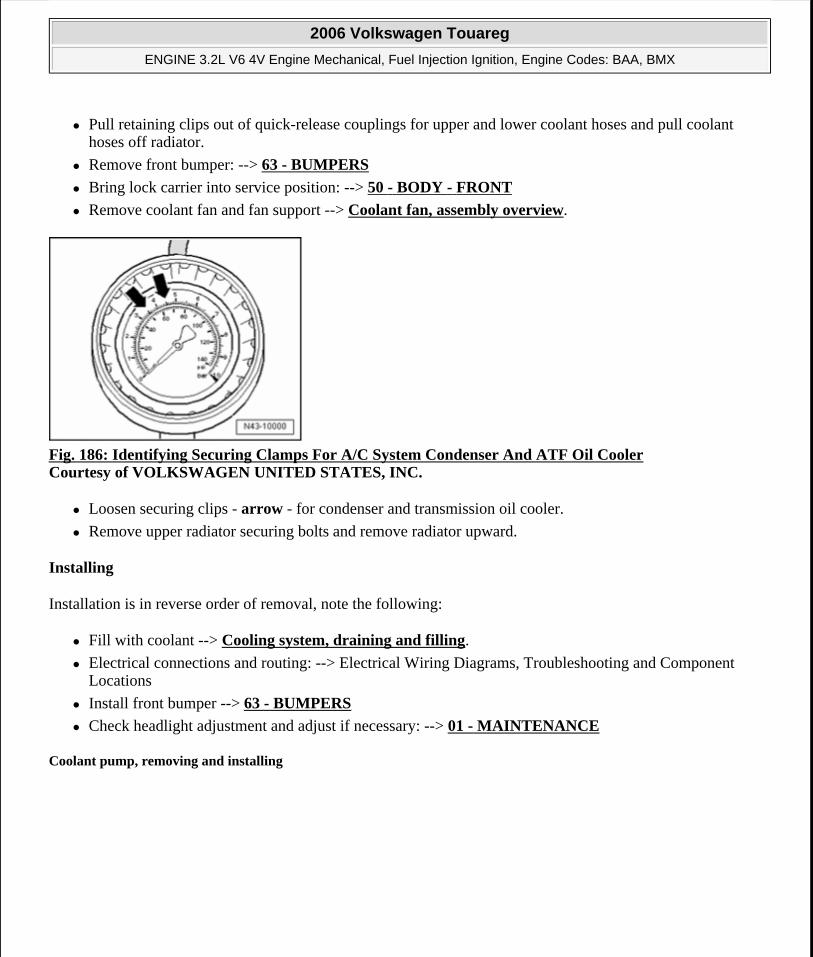
Pull retaining clips out of quick-release couplings for upper and lower coolant hoses and pull coolant hoses off radiator.
Remove front bumper: --> 63 - BUMPERS
Bring lock carrier into service position: --> 50 - BODY - FRONT
Remove coolant fan and fan support --> Coolant fan, assembly overview.
Fig. 186: Identifying Securing Clamps For A/C System Condenser And ATF Oil Cooler Courtesy of VOLKSWAGEN UNITED STATES, INC.
Loosen securing clips - arrow - for condenser and transmission oil cooler.
Remove upper radiator securing bolts and remove radiator upward.
Installing
Installation is in reverse order of removal, note the following:
Fill with coolant --> Cooling system, draining and filling.
Electrical connections and routing: --> Electrical Wiring Diagrams, Troubleshooting and Component Locations
Install front bumper --> 63 - BUMPERS
Check headlight adjustment and adjust if necessary: --> 01 - MAINTENANCE
Coolant pump, removing and installing
2006 Volkswagen Touareg
ENGINE 3.2L V6 4V Engine Mechanical, Fuel Injection Ignition, Engine Codes: BAA, BMX
Microsoft
Sunday, September 20, 2009 9:14:18 AM Page 163 © 2005 Mitchell Repair Information Company, LLC.
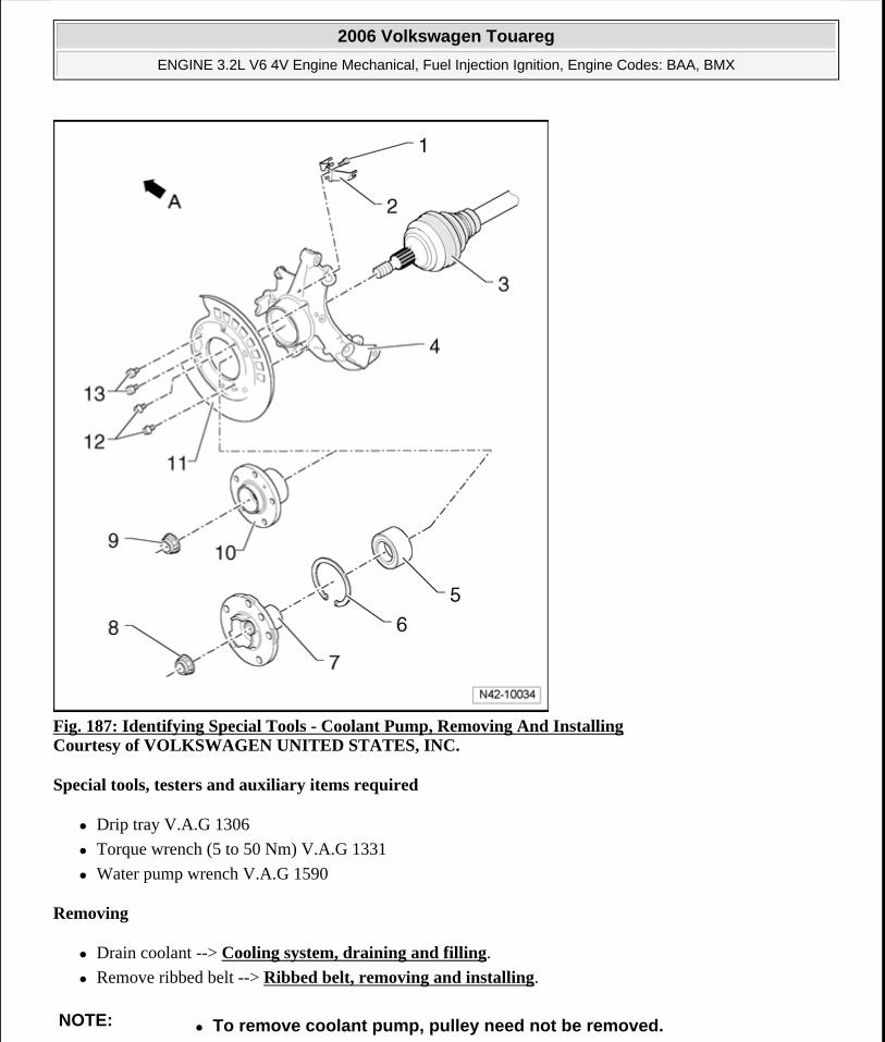
Fig. 187: Identifying Special Tools - Coolant Pump, Removing And Installing Courtesy of VOLKSWAGEN UNITED STATES, INC.
Special tools, testers and auxiliary items required
Drip tray V.A.G 1306
Torque wrench (5 to 50 Nm) V.A.G 1331
Water pump wrench V.A.G 1590
Removing
Drain coolant --> Cooling system, draining and filling.
Remove ribbed belt --> Ribbed belt, removing and installing.
NOTE: To remove coolant pump, pulley need not be removed.
2006 Volkswagen Touareg
ENGINE 3.2L V6 4V Engine Mechanical, Fuel Injection Ignition, Engine Codes: BAA, BMX
Microsoft
Sunday, September 20, 2009 9:14:18 AM Page 164 © 2005 Mitchell Repair Information Company, LLC.
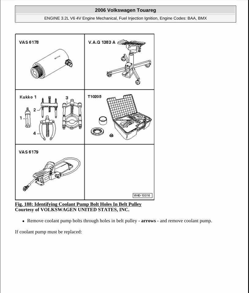
Fig. 188: Identifying Coolant Pump Bolt Holes In Belt Pulley Courtesy of VOLKSWAGEN UNITED STATES, INC.
Remove coolant pump bolts through holes in belt pulley - arrows - and remove coolant pump.
If coolant pump must be replaced:
2006 Volkswagen Touareg
ENGINE 3.2L V6 4V Engine Mechanical, Fuel Injection Ignition, Engine Codes: BAA, BMX
Microsoft
Sunday, September 20, 2009 9:14:18 AM Page 165 © 2005 Mitchell Repair Information Company, LLC.
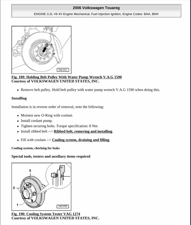
Fig. 189: Holding Belt Pulley With Water Pump Wrench V.A.G 1590 Courtesy of VOLKSWAGEN UNITED STATES, INC.
Remove belt pulley. Hold belt pulley with water pump wrench V.A.G 1590 when doing this.
Installing
Installation is in reverse order of removal, note the following:
Moisten new O-Ring with coolant.
Install coolant pump.
Tighten securing bolts. Torque specification: 8 Nm
Install ribbed belt --> Ribbed belt, removing and installing.
Fill with coolant --> Cooling system, draining and filling.
Cooling system, checking for leaks
Special tools, testers and auxiliary items required
Fig. 190: Cooling System Tester VAG 1274 Courtesy of VOLKSWAGEN UNITED STATES, INC.
2006 Volkswagen Touareg
ENGINE 3.2L V6 4V Engine Mechanical, Fuel Injection Ignition, Engine Codes: BAA, BMX
Microsoft
Sunday, September 20, 2009 9:14:18 AM Page 166 © 2005 Mitchell Repair Information Company, LLC.
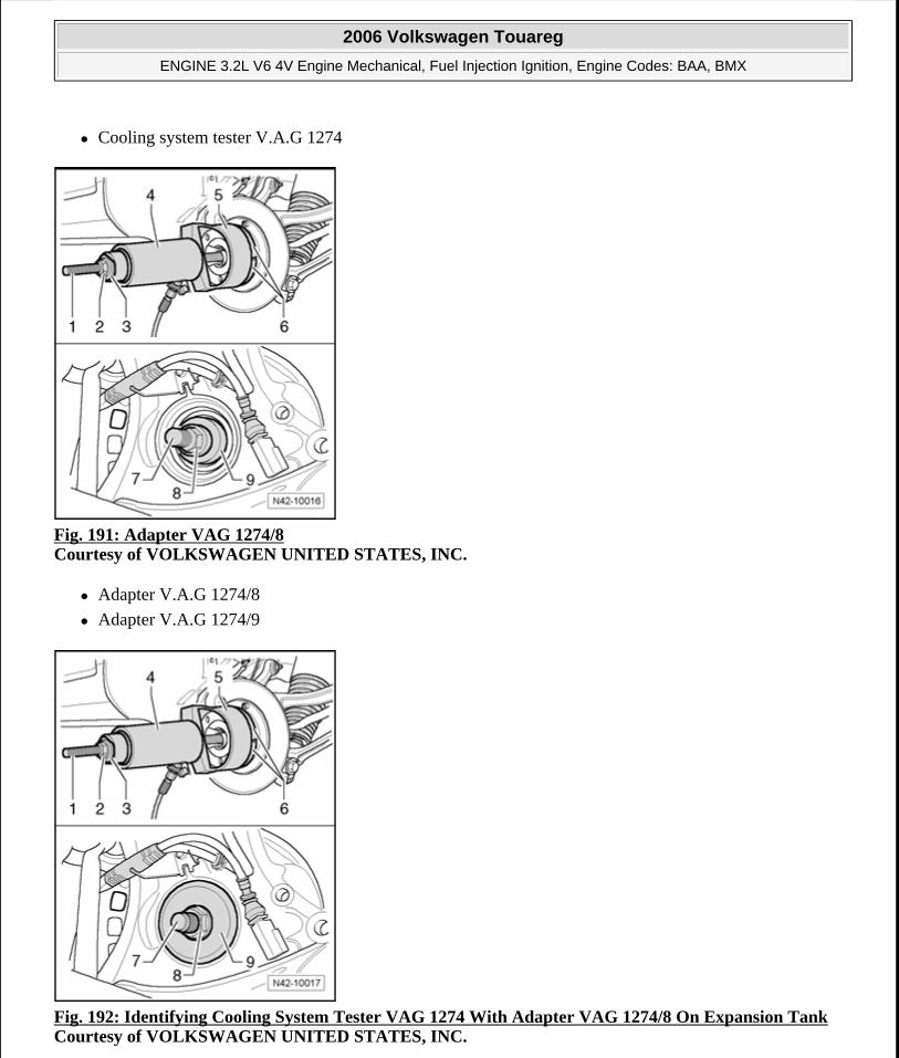
Cooling system tester V.A.G 1274
Fig. 191: Adapter VAG 1274/8 Courtesy of VOLKSWAGEN UNITED STATES, INC.
Adapter V.A.G 1274/8
Adapter V.A.G 1274/9
Fig. 192: Identifying Cooling System Tester VAG 1274 With Adapter VAG 1274/8 On Expansion Tank Courtesy of VOLKSWAGEN UNITED STATES, INC.
2006 Volkswagen Touareg
ENGINE 3.2L V6 4V Engine Mechanical, Fuel Injection Ignition, Engine Codes: BAA, BMX
Microsoft
Sunday, September 20, 2009 9:14:18 AM Page 167 © 2005 Mitchell Repair Information Company, LLC.
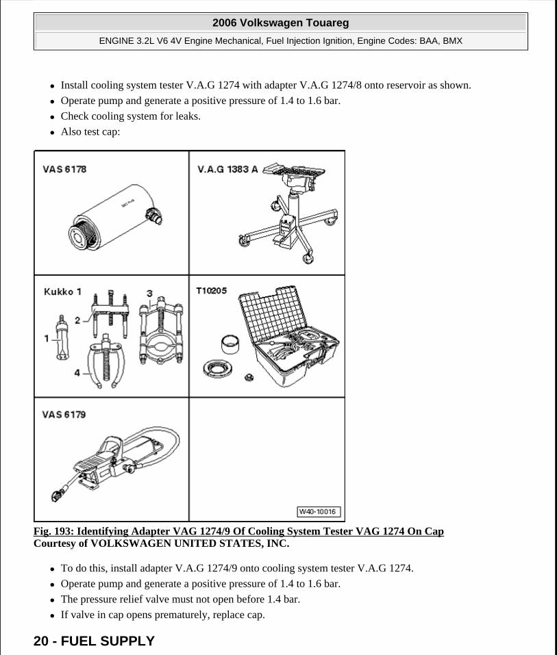
Install cooling system tester V.A.G 1274 with adapter V.A.G 1274/8 onto reservoir as shown.
Operate pump and generate a positive pressure of 1.4 to 1.6 bar.
Check cooling system for leaks.
Also test cap:
Fig. 193: Identifying Adapter VAG 1274/9 Of Cooling System Tester VAG 1274 On Cap Courtesy of VOLKSWAGEN UNITED STATES, INC.
To do this, install adapter V.A.G 1274/9 onto cooling system tester V.A.G 1274.
Operate pump and generate a positive pressure of 1.4 to 1.6 bar.
The pressure relief valve must not open before 1.4 bar.
If valve in cap opens prematurely, replace cap.
20 - FUEL SUPPLY
2006 Volkswagen Touareg
ENGINE 3.2L V6 4V Engine Mechanical, Fuel Injection Ignition, Engine Codes: BAA, BMX
Microsoft
Sunday, September 20, 2009 9:14:18 AM Page 168 © 2005 Mitchell Repair Information Company, LLC.
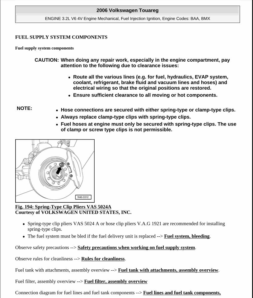
FUEL SUPPLY SYSTEM COMPONENTS
Fuel supply system components
Fig. 194: Spring-Type Clip Pliers VAS 5024A Courtesy of VOLKSWAGEN UNITED STATES, INC.
Spring-type clip pliers VAS 5024 A or hose clip pliers V.A.G 1921 are recommended for installing spring-type clips.
The fuel system must be bled if the fuel delivery unit is replaced --> Fuel system, bleeding.
Observe safety precautions --> Safety precautions when working on fuel supply system.
Observe rules for cleanliness --> Rules for cleanliness.
Fuel tank with attachments, assembly overview --> Fuel tank with attachments, assembly overview.
Fuel filter, assembly overview --> Fuel filter, assembly overview
Connection diagram for fuel lines and fuel tank components --> Fuel lines and fuel tank components,
CAUTION: When doing any repair work, especially in the engine compartment, pay attention to the following due to clearance issues:
Route all the various lines (e.g. for fuel, hydraulics, EVAP system, coolant, refrigerant, brake fluid and vacuum lines and hoses) and electrical wiring so that the original positions are restored.
Ensure sufficient clearance to all moving or hot components.
NOTE: Hose connections are secured with either spring-type or clamp-type clips.
Always replace clamp-type clips with spring-type clips.
Fuel hoses at engine must only be secured with spring-type clips. The use of clamp or screw type clips is not permissible.
2006 Volkswagen Touareg
ENGINE 3.2L V6 4V Engine Mechanical, Fuel Injection Ignition, Engine Codes: BAA, BMX
Microsoft
Sunday, September 20, 2009 9:14:18 AM Page 169 © 2005 Mitchell Repair Information Company, LLC.
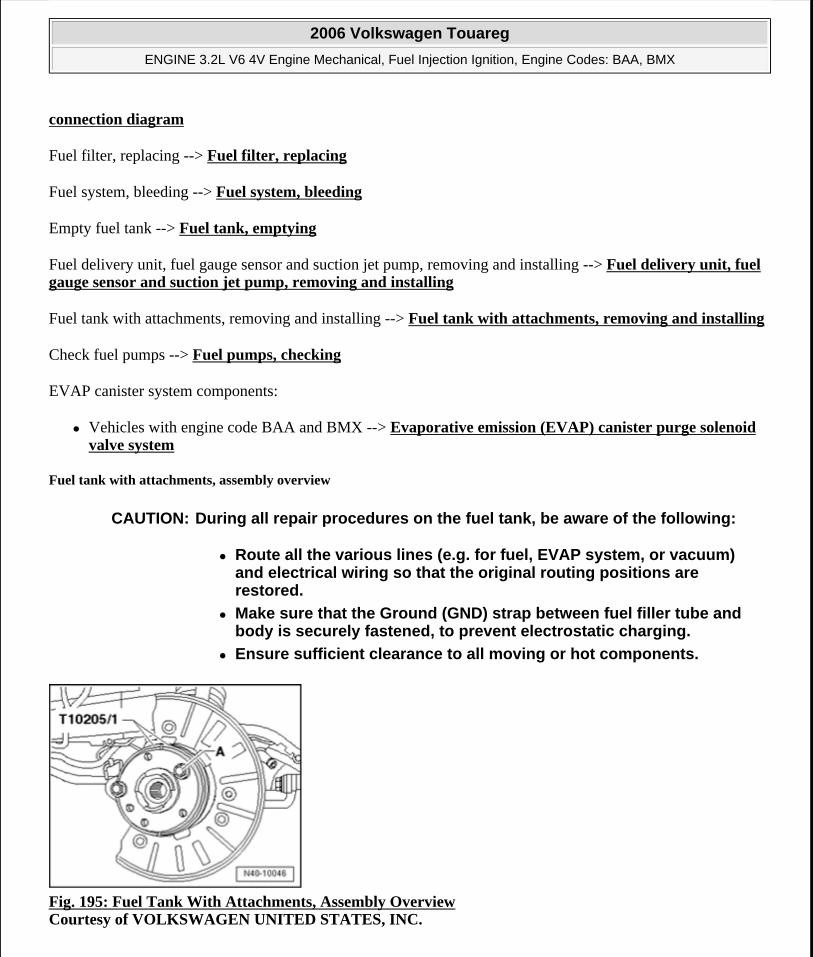
connection diagram
Fuel filter, replacing --> Fuel filter, replacing
Fuel system, bleeding --> Fuel system, bleeding
Empty fuel tank --> Fuel tank, emptying
Fuel delivery unit, fuel gauge sensor and suction jet pump, removing and installing --> Fuel delivery unit, fuel gauge sensor and suction jet pump, removing and installing
Fuel tank with attachments, removing and installing --> Fuel tank with attachments, removing and installing
Check fuel pumps --> Fuel pumps, checking
EVAP canister system components:
Vehicles with engine code BAA and BMX --> Evaporative emission (EVAP) canister purge solenoid valve system
Fuel tank with attachments, assembly overview
Fig. 195: Fuel Tank With Attachments, Assembly Overview Courtesy of VOLKSWAGEN UNITED STATES, INC.
CAUTION: During all repair procedures on the fuel tank, be aware of the following:
Route all the various lines (e.g. for fuel, EVAP system, or vacuum) and electrical wiring so that the original routing positions are restored.
Make sure that the Ground (GND) strap between fuel filler tube and body is securely fastened, to prevent electrostatic charging.
Ensure sufficient clearance to all moving or hot components.
2006 Volkswagen Touareg
ENGINE 3.2L V6 4V Engine Mechanical, Fuel Injection Ignition, Engine Codes: BAA, BMX
Microsoft
Sunday, September 20, 2009 9:14:18 AM Page 170 © 2005 Mitchell Repair Information Company, LLC.
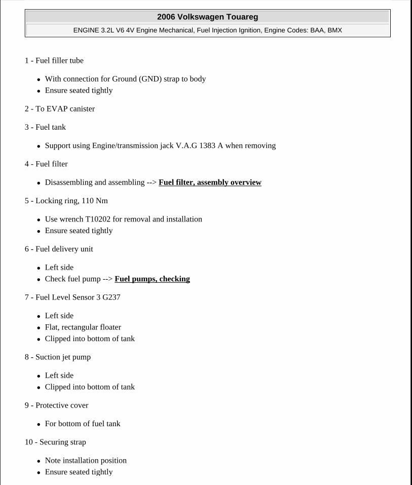
1 - Fuel filler tube
With connection for Ground (GND) strap to body
Ensure seated tightly
2 - To EVAP canister
3 - Fuel tank
Support using Engine/transmission jack V.A.G 1383 A when removing
4 - Fuel filter
Disassembling and assembling --> Fuel filter, assembly overview
5 - Locking ring, 110 Nm
Use wrench T10202 for removal and installation
Ensure seated tightly
6 - Fuel delivery unit
Left side
Check fuel pump --> Fuel pumps, checking
7 - Fuel Level Sensor 3 G237
Left side
Flat, rectangular floater
Clipped into bottom of tank
8 - Suction jet pump
Left side
Clipped into bottom of tank
9 - Protective cover
For bottom of fuel tank
10 - Securing strap
Note installation position
Ensure seated tightly
2006 Volkswagen Touareg
ENGINE 3.2L V6 4V Engine Mechanical, Fuel Injection Ignition, Engine Codes: BAA, BMX
Microsoft
Sunday, September 20, 2009 9:14:18 AM Page 171 © 2005 Mitchell Repair Information Company, LLC.
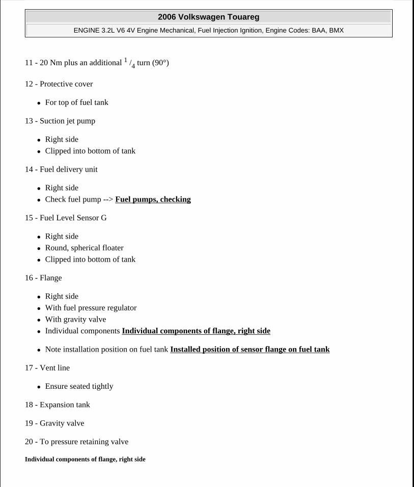
11 - 20 Nm plus an additional 1 /4 turn (90°)
12 - Protective cover
For top of fuel tank
13 - Suction jet pump
Right side
Clipped into bottom of tank
14 - Fuel delivery unit
Right side
Check fuel pump --> Fuel pumps, checking
15 - Fuel Level Sensor G
Right side
Round, spherical floater
Clipped into bottom of tank
16 - Flange
Right side
With fuel pressure regulator
With gravity valve
Individual components Individual components of flange, right side
Note installation position on fuel tank Installed position of sensor flange on fuel tank
17 - Vent line
Ensure seated tightly
18 - Expansion tank
19 - Gravity valve
20 - To pressure retaining valve
Individual components of flange, right side
2006 Volkswagen Touareg
ENGINE 3.2L V6 4V Engine Mechanical, Fuel Injection Ignition, Engine Codes: BAA, BMX
Microsoft
Sunday, September 20, 2009 9:14:18 AM Page 172 © 2005 Mitchell Repair Information Company, LLC.
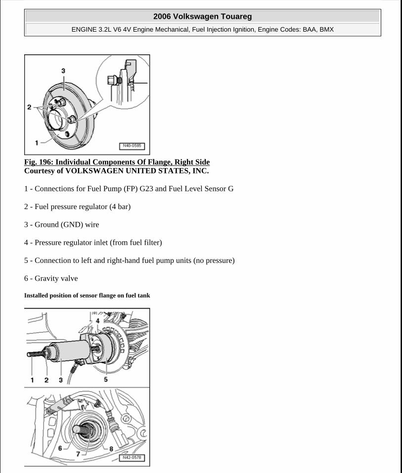
Fig. 196: Individual Components Of Flange, Right Side Courtesy of VOLKSWAGEN UNITED STATES, INC.
1 - Connections for Fuel Pump (FP) G23 and Fuel Level Sensor G
2 - Fuel pressure regulator (4 bar)
3 - Ground (GND) wire
4 - Pressure regulator inlet (from fuel filter)
5 - Connection to left and right-hand fuel pump units (no pressure)
6 - Gravity valve
Installed position of sensor flange on fuel tank
2006 Volkswagen Touareg
ENGINE 3.2L V6 4V Engine Mechanical, Fuel Injection Ignition, Engine Codes: BAA, BMX
Microsoft
Sunday, September 20, 2009 9:14:18 AM Page 173 © 2005 Mitchell Repair Information Company, LLC.
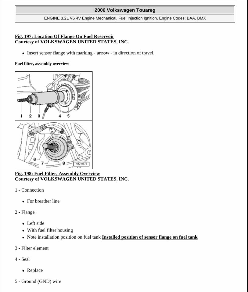
Fig. 197: Location Of Flange On Fuel ReservoirCourtesy of VOLKSWAGEN UNITED STATES, INC.
Insert sensor flange with marking - arrow - in direction of travel.
Fuel filter, assembly overview
Fig. 198: Fuel Filter, Assembly Overview Courtesy of VOLKSWAGEN UNITED STATES, INC.
1 - Connection
For breather line
2 - Flange
Left side
With fuel filter housing
Note installation position on fuel tank Installed position of sensor flange on fuel tank
3 - Filter element
4 - Seal
Replace
5 - Ground (GND) wire
2006 Volkswagen Touareg
ENGINE 3.2L V6 4V Engine Mechanical, Fuel Injection Ignition, Engine Codes: BAA, BMX
Microsoft
Sunday, September 20, 2009 9:14:18 AM Page 174 © 2005 Mitchell Repair Information Company, LLC.
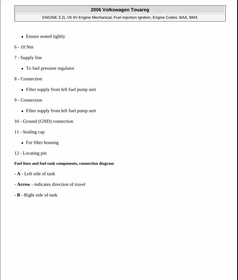
Ensure seated tightly
6 - 10 Nm
7 - Supply line
To fuel pressure regulator
8 - Connection
Filter supply from left fuel pump unit
9 - Connection
Filter supply from left fuel pump unit
10 - Ground (GND) connection
11 - Sealing cap
For filter housing
12 - Locating pin
Fuel lines and fuel tank components, connection diagram
- A - Left side of tank
- Arrow - indicates direction of travel
- B - Right side of tank
2006 Volkswagen Touareg
ENGINE 3.2L V6 4V Engine Mechanical, Fuel Injection Ignition, Engine Codes: BAA, BMX
Microsoft
Sunday, September 20, 2009 9:14:18 AM Page 175 © 2005 Mitchell Repair Information Company, LLC.
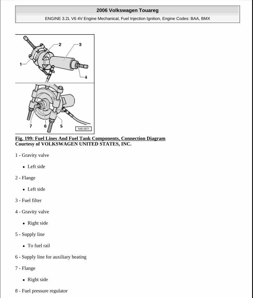
Fig. 199: Fuel Lines And Fuel Tank Components, Connection Diagram Courtesy of VOLKSWAGEN UNITED STATES, INC.
1 - Gravity valve
Left side
2 - Flange
Left side
3 - Fuel filter
4 - Gravity valve
Right side
5 - Supply line
To fuel rail
6 - Supply line for auxiliary heating
7 - Flange
Right side
8 - Fuel pressure regulator
2006 Volkswagen Touareg
ENGINE 3.2L V6 4V Engine Mechanical, Fuel Injection Ignition, Engine Codes: BAA, BMX
Microsoft
Sunday, September 20, 2009 9:14:18 AM Page 176 © 2005 Mitchell Repair Information Company, LLC.
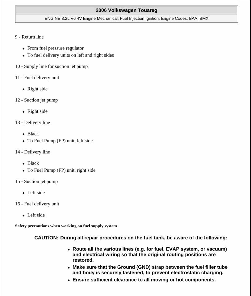
9 - Return line
From fuel pressure regulator
To fuel delivery units on left and right sides
10 - Supply line for suction jet pump
11 - Fuel delivery unit
Right side
12 - Suction jet pump
Right side
13 - Delivery line
Black
To Fuel Pump (FP) unit, left side
14 - Delivery line
Black
To Fuel Pump (FP) unit, right side
15 - Suction jet pump
Left side
16 - Fuel delivery unit
Left side
Safety precautions when working on fuel supply system
CAUTION: During all repair procedures on the fuel tank, be aware of the following:
Route all the various lines (e.g. for fuel, EVAP system, or vacuum) and electrical wiring so that the original routing positions are restored.
Make sure that the Ground (GND) strap between the fuel filler tube and body is securely fastened, to prevent electrostatic charging.
Ensure sufficient clearance to all moving or hot components.
2006 Volkswagen Touareg
ENGINE 3.2L V6 4V Engine Mechanical, Fuel Injection Ignition, Engine Codes: BAA, BMX
Microsoft
Sunday, September 20, 2009 9:14:18 AM Page 177 © 2005 Mitchell Repair Information Company, LLC.
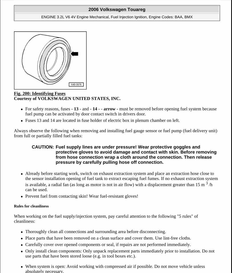
Fig. 200: Identifying Fuses Courtesy of VOLKSWAGEN UNITED STATES, INC.
For safety reasons, fuses - 13 - and - 14 - - arrow - must be removed before opening fuel system because fuel pump can be activated by door contact switch in drivers door.
Fuses 13 and 14 are located in fuse holder of electric box in plenum chamber on left.
Always observe the following when removing and installing fuel gauge sensor or fuel pump (fuel delivery unit) from full or partially filled fuel tanks:
Already before starting work, switch on exhaust extraction system and place an extraction hose close to the sensor installation opening of fuel tank to extract escaping fuel fumes. If no exhaust extraction system is available, a radial fan (as long as motor is not in air flow) with a displacement greater than 15 m 3 /h can be used.
Prevent fuel from contacting skin! Wear fuel-resistant gloves!
Rules for cleanliness
When working on the fuel supply/injection system, pay careful attention to the following "5 rules" of cleanliness:
Thoroughly clean all connections and surrounding area before disconnecting.
Place parts that have been removed on a clean surface and cover them. Use lint-free cloths.
Carefully cover over opened components or seal, if repairs are not performed immediately.
Only install clean components: Only unpack replacement parts immediately prior to installation. Do not use parts that have been stored loose (e.g. in tool boxes etc.).
When system is open: Avoid working with compressed air if possible. Do not move vehicle unless absolutely necessary.
CAUTION: Fuel supply lines are under pressure! Wear protective goggles and protective gloves to avoid damage and contact with skin. Before removing from hose connection wrap a cloth around the connection. Then release pressure by carefully pulling hose off connection.
2006 Volkswagen Touareg
ENGINE 3.2L V6 4V Engine Mechanical, Fuel Injection Ignition, Engine Codes: BAA, BMX
Microsoft
Sunday, September 20, 2009 9:14:18 AM Page 178 © 2005 Mitchell Repair Information Company, LLC.
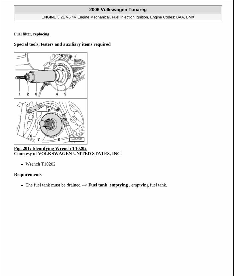
Fuel filter, replacing
Special tools, testers and auxiliary items required
Fig. 201: Identifying Wrench T10202 Courtesy of VOLKSWAGEN UNITED STATES, INC.
Wrench T10202
Requirements
The fuel tank must be drained --> Fuel tank, emptying , emptying fuel tank.
2006 Volkswagen Touareg
ENGINE 3.2L V6 4V Engine Mechanical, Fuel Injection Ignition, Engine Codes: BAA, BMX
Microsoft
Sunday, September 20, 2009 9:14:18 AM Page 179 © 2005 Mitchell Repair Information Company, LLC.
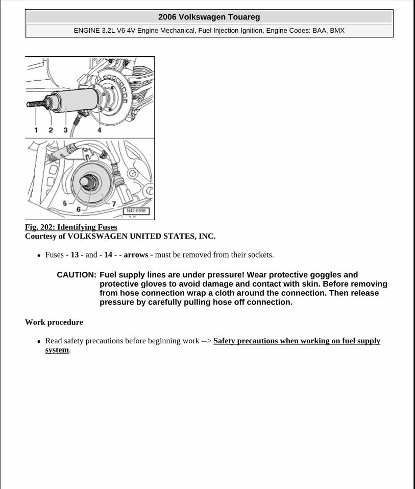
Fig. 202: Identifying Fuses Courtesy of VOLKSWAGEN UNITED STATES, INC.
Fuses - 13 - and - 14 - - arrows - must be removed from their sockets.
Work procedure
Read safety precautions before beginning work --> Safety precautions when working on fuel supply system.
CAUTION: Fuel supply lines are under pressure! Wear protective goggles and protective gloves to avoid damage and contact with skin. Before removing from hose connection wrap a cloth around the connection. Then release pressure by carefully pulling hose off connection.
2006 Volkswagen Touareg
ENGINE 3.2L V6 4V Engine Mechanical, Fuel Injection Ignition, Engine Codes: BAA, BMX
Microsoft
Sunday, September 20, 2009 9:14:18 AM Page 180 © 2005 Mitchell Repair Information Company, LLC.
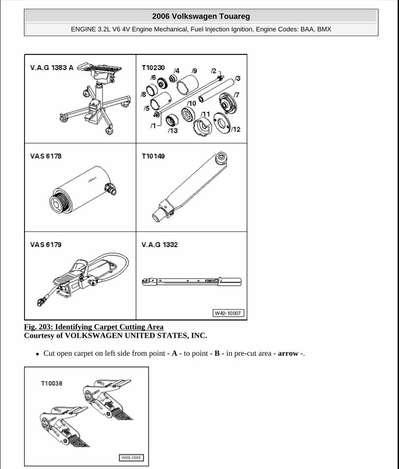
Fig. 203: Identifying Carpet Cutting Area Courtesy of VOLKSWAGEN UNITED STATES, INC.
Cut open carpet on left side from point - A - to point - B - in pre-cut area - arrow -.
2006 Volkswagen Touareg
ENGINE 3.2L V6 4V Engine Mechanical, Fuel Injection Ignition, Engine Codes: BAA, BMX
Microsoft
Sunday, September 20, 2009 9:14:18 AM Page 181 © 2005 Mitchell Repair Information Company, LLC.
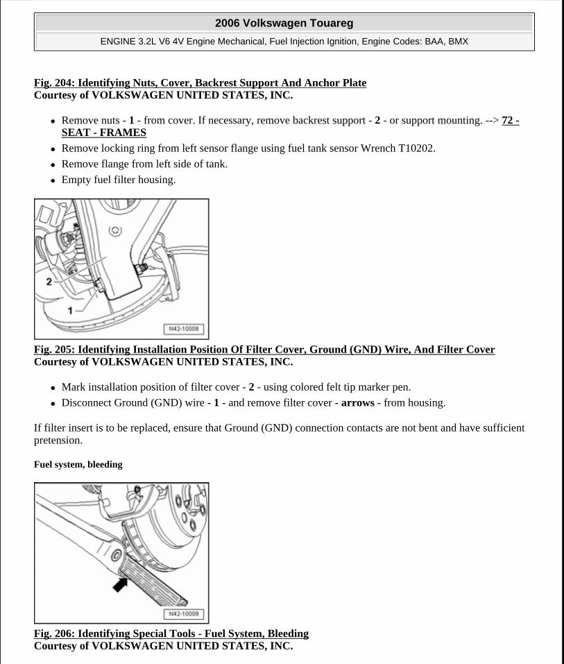
Fig. 204: Identifying Nuts, Cover, Backrest Support And Anchor PlateCourtesy of VOLKSWAGEN UNITED STATES, INC.
Remove nuts - 1 - from cover. If necessary, remove backrest support - 2 - or support mounting. --> 72 - SEAT - FRAMES
Remove locking ring from left sensor flange using fuel tank sensor Wrench T10202.
Remove flange from left side of tank.
Empty fuel filter housing.
Fig. 205: Identifying Installation Position Of Filter Cover, Ground (GND) Wire, And Filter Cover Courtesy of VOLKSWAGEN UNITED STATES, INC.
Mark installation position of filter cover - 2 - using colored felt tip marker pen.
Disconnect Ground (GND) wire - 1 - and remove filter cover - arrows - from housing.
If filter insert is to be replaced, ensure that Ground (GND) connection contacts are not bent and have sufficient pretension.
Fuel system, bleeding
Fig. 206: Identifying Special Tools - Fuel System, Bleeding Courtesy of VOLKSWAGEN UNITED STATES, INC.
2006 Volkswagen Touareg
ENGINE 3.2L V6 4V Engine Mechanical, Fuel Injection Ignition, Engine Codes: BAA, BMX
Microsoft
Sunday, September 20, 2009 9:14:18 AM Page 182 © 2005 Mitchell Repair Information Company, LLC.
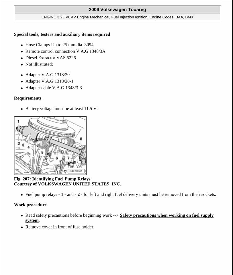
Special tools, testers and auxiliary items required
Hose Clamps Up to 25 mm dia. 3094
Remote control connection V.A.G 1348/3A
Diesel Extractor VAS 5226
Not illustrated:
Adapter V.A.G 1318/20
Adapter V.A.G 1318/20-1
Adapter cable V.A.G 1348/3-3
Requirements
Battery voltage must be at least 11.5 V.
Fig. 207: Identifying Fuel Pump Relays Courtesy of VOLKSWAGEN UNITED STATES, INC.
Fuel pump relays - 1 - and - 2 - for left and right fuel delivery units must be removed from their sockets.
Work procedure
Read safety precautions before beginning work --> Safety precautions when working on fuel supply system.
Remove cover in front of fuse holder.
2006 Volkswagen Touareg
ENGINE 3.2L V6 4V Engine Mechanical, Fuel Injection Ignition, Engine Codes: BAA, BMX
Microsoft
Sunday, September 20, 2009 9:14:18 AM Page 183 © 2005 Mitchell Repair Information Company, LLC.
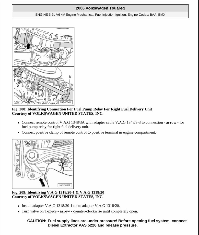
Fig. 208: Identifying Connection For Fuel Pump Relay For Right Fuel Delivery Unit Courtesy of VOLKSWAGEN UNITED STATES, INC.
Connect remote control V.A.G 1348/3A with adapter cable V.A.G 1348/3-3 to connection - arrow - for fuel pump relay for right fuel delivery unit.
Connect positive clamp of remote control to positive terminal in engine compartment.
Fig. 209: Identifying V.A.G 1318/20-1 & V.A.G 1318/20 Courtesy of VOLKSWAGEN UNITED STATES, INC.
Install adapter V.A.G 1318/20-1 on to adapter V.A.G 1318/20.
Turn valve on T-piece - arrow - counter-clockwise until completely open.
CAUTION: Fuel supply lines are under pressure! Before opening fuel system, connect Diesel Extractor VAS 5226 and release pressure.
2006 Volkswagen Touareg
ENGINE 3.2L V6 4V Engine Mechanical, Fuel Injection Ignition, Engine Codes: BAA, BMX
Microsoft
Sunday, September 20, 2009 9:14:18 AM Page 184 © 2005 Mitchell Repair Information Company, LLC.
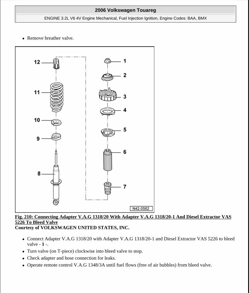
Remove breather valve.
Fig. 210: Connecting Adapter V.A.G 1318/20 With Adapter V.A.G 1318/20-1 And Diesel Extractor VAS 5226 To Bleed Valve Courtesy of VOLKSWAGEN UNITED STATES, INC.
Connect Adapter V.A.G 1318/20 with Adapter V.A.G 1318/20-1 and Diesel Extractor VAS 5226 to bleed valve - 1 -.
Turn valve (on T-piece) clockwise into bleed valve to stop.
Check adapter and hose connection for leaks.
Operate remote control V.A.G 1348/3A until fuel flows (free of air bubbles) from bleed valve.
2006 Volkswagen Touareg
ENGINE 3.2L V6 4V Engine Mechanical, Fuel Injection Ignition, Engine Codes: BAA, BMX
Microsoft
Sunday, September 20, 2009 9:14:18 AM Page 185 © 2005 Mitchell Repair Information Company, LLC.
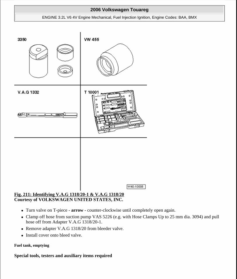
Fig. 211: Identifying V.A.G 1318/20-1 & V.A.G 1318/20 Courtesy of VOLKSWAGEN UNITED STATES, INC.
Turn valve on T-piece - arrow - counter-clockwise until completely open again.
Clamp off hose from suction pump VAS 5226 (e.g. with Hose Clamps Up to 25 mm dia. 3094) and pull hose off from Adapter V.A.G 1318/20-1.
Remove adapter V.A.G 1318/20 from bleeder valve.
Install cover onto bleed valve.
Fuel tank, emptying
Special tools, testers and auxiliary items required
2006 Volkswagen Touareg
ENGINE 3.2L V6 4V Engine Mechanical, Fuel Injection Ignition, Engine Codes: BAA, BMX
Microsoft
Sunday, September 20, 2009 9:14:18 AM Page 186 © 2005 Mitchell Repair Information Company, LLC.
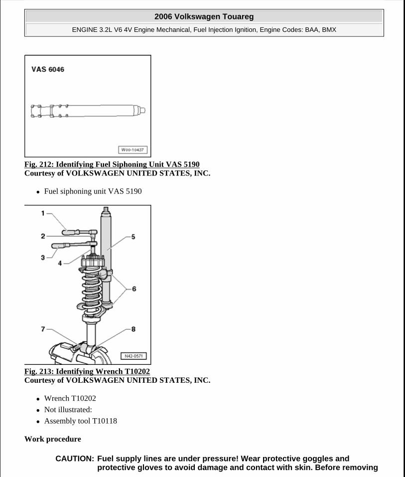
Fig. 212: Identifying Fuel Siphoning Unit VAS 5190 Courtesy of VOLKSWAGEN UNITED STATES, INC.
Fuel siphoning unit VAS 5190
Fig. 213: Identifying Wrench T10202 Courtesy of VOLKSWAGEN UNITED STATES, INC.
Wrench T10202
Not illustrated:
Assembly tool T10118
Work procedure
CAUTION: Fuel supply lines are under pressure! Wear protective goggles and protective gloves to avoid damage and contact with skin. Before removing
2006 Volkswagen Touareg
ENGINE 3.2L V6 4V Engine Mechanical, Fuel Injection Ignition, Engine Codes: BAA, BMX
Microsoft
Sunday, September 20, 2009 9:14:18 AM Page 187 © 2005 Mitchell Repair Information Company, LLC.
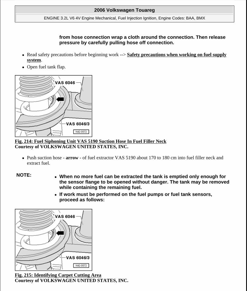
Read safety precautions before beginning work --> Safety precautions when working on fuel supply system.
Open fuel tank flap.
Fig. 214: Fuel Siphoning Unit VAS 5190 Suction Hose In Fuel Filler Neck Courtesy of VOLKSWAGEN UNITED STATES, INC.
Push suction hose - arrow - of fuel extractor VAS 5190 about 170 to 180 cm into fuel filler neck and extract fuel.
Fig. 215: Identifying Carpet Cutting Area Courtesy of VOLKSWAGEN UNITED STATES, INC.
from hose connection wrap a cloth around the connection. Then release pressure by carefully pulling hose off connection.
NOTE: When no more fuel can be extracted the tank is emptied only enough for the sensor flange to be opened without danger. The tank may be removed while containing the remaining fuel.
If work must be performed on the fuel pumps or fuel tank sensors, proceed as follows:
2006 Volkswagen Touareg
ENGINE 3.2L V6 4V Engine Mechanical, Fuel Injection Ignition, Engine Codes: BAA, BMX
Microsoft
Sunday, September 20, 2009 9:14:18 AM Page 188 © 2005 Mitchell Repair Information Company, LLC.
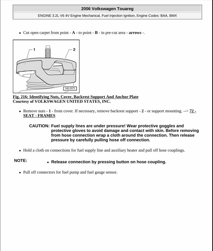
Cut open carpet from point - A - to point - B - in pre-cut area - arrows -.
Fig. 216: Identifying Nuts, Cover, Backrest Support And Anchor Plate Courtesy of VOLKSWAGEN UNITED STATES, INC.
Remove nuts - 1 - from cover. If necessary, remove backrest support - 2 - or support mounting. --> 72 - SEAT - FRAMES
Hold a cloth on connections for fuel supply line and auxiliary heater and pull off hose couplings.
Pull off connectors for fuel pump and fuel gauge sensor.
CAUTION: Fuel supply lines are under pressure! Wear protective goggles and protective gloves to avoid damage and contact with skin. Before removing from hose connection wrap a cloth around the connection. Then release pressure by carefully pulling hose off connection.
NOTE: Release connection by pressing button on hose coupling.
2006 Volkswagen Touareg
ENGINE 3.2L V6 4V Engine Mechanical, Fuel Injection Ignition, Engine Codes: BAA, BMX
Microsoft
Sunday, September 20, 2009 9:14:19 AM Page 189 © 2005 Mitchell Repair Information Company, LLC.
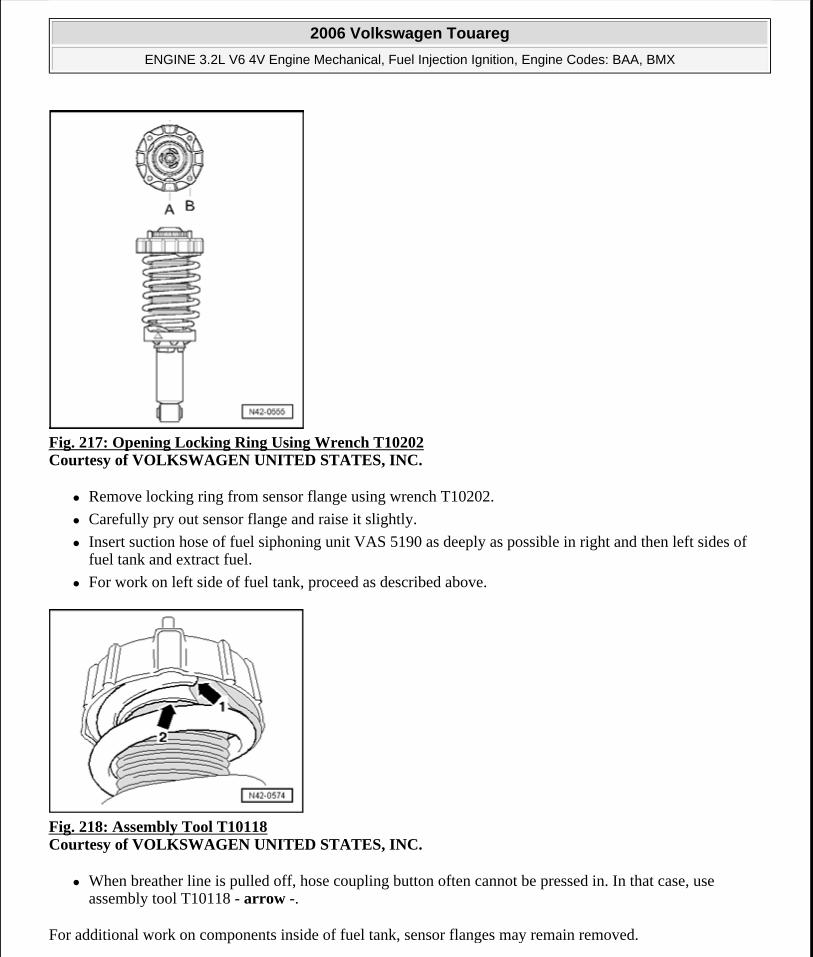
Fig. 217: Opening Locking Ring Using Wrench T10202 Courtesy of VOLKSWAGEN UNITED STATES, INC.
Remove locking ring from sensor flange using wrench T10202.
Carefully pry out sensor flange and raise it slightly.
Insert suction hose of fuel siphoning unit VAS 5190 as deeply as possible in right and then left sides of fuel tank and extract fuel.
For work on left side of fuel tank, proceed as described above.
Fig. 218: Assembly Tool T10118 Courtesy of VOLKSWAGEN UNITED STATES, INC.
When breather line is pulled off, hose coupling button often cannot be pressed in. In that case, use assembly tool T10118 - arrow -.
For additional work on components inside of fuel tank, sensor flanges may remain removed.
2006 Volkswagen Touareg
ENGINE 3.2L V6 4V Engine Mechanical, Fuel Injection Ignition, Engine Codes: BAA, BMX
Microsoft
Sunday, September 20, 2009 9:14:19 AM Page 190 © 2005 Mitchell Repair Information Company, LLC.
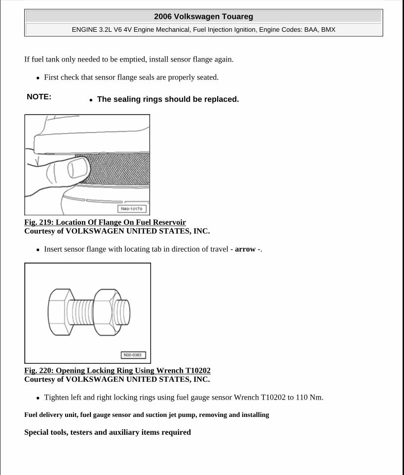
If fuel tank only needed to be emptied, install sensor flange again.
First check that sensor flange seals are properly seated.
Fig. 219: Location Of Flange On Fuel Reservoir Courtesy of VOLKSWAGEN UNITED STATES, INC.
Insert sensor flange with locating tab in direction of travel - arrow -.
Fig. 220: Opening Locking Ring Using Wrench T10202 Courtesy of VOLKSWAGEN UNITED STATES, INC.
Tighten left and right locking rings using fuel gauge sensor Wrench T10202 to 110 Nm.
Fuel delivery unit, fuel gauge sensor and suction jet pump, removing and installing
Special tools, testers and auxiliary items required
NOTE: The sealing rings should be replaced.
2006 Volkswagen Touareg
ENGINE 3.2L V6 4V Engine Mechanical, Fuel Injection Ignition, Engine Codes: BAA, BMX
Microsoft
Sunday, September 20, 2009 9:14:19 AM Page 191 © 2005 Mitchell Repair Information Company, LLC.
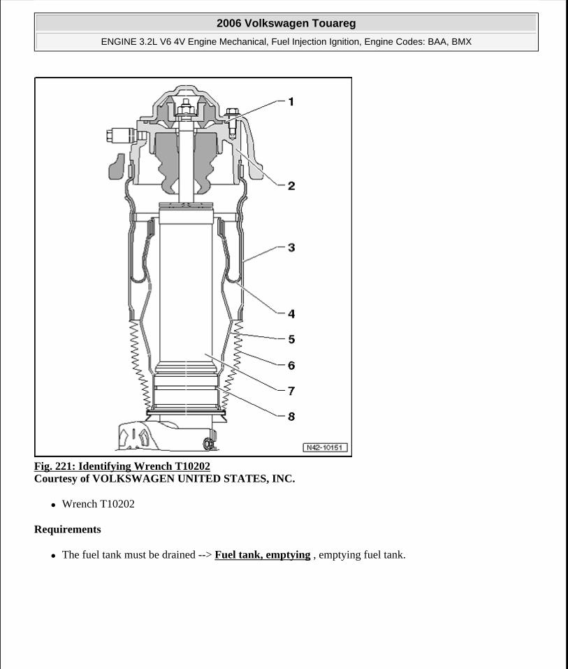
Fig. 221: Identifying Wrench T10202 Courtesy of VOLKSWAGEN UNITED STATES, INC.
Wrench T10202
Requirements
The fuel tank must be drained --> Fuel tank, emptying , emptying fuel tank.
2006 Volkswagen Touareg
ENGINE 3.2L V6 4V Engine Mechanical, Fuel Injection Ignition, Engine Codes: BAA, BMX
Microsoft
Sunday, September 20, 2009 9:14:19 AM Page 192 © 2005 Mitchell Repair Information Company, LLC.
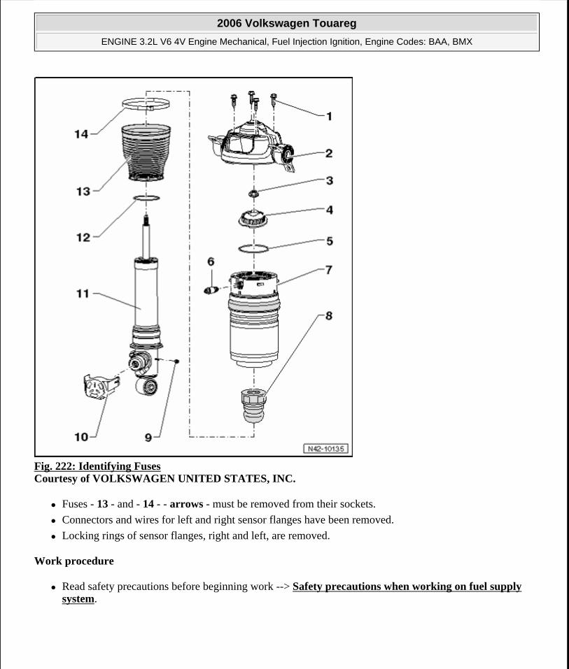
Fig. 222: Identifying Fuses Courtesy of VOLKSWAGEN UNITED STATES, INC.
Fuses - 13 - and - 14 - - arrows - must be removed from their sockets.
Connectors and wires for left and right sensor flanges have been removed.
Locking rings of sensor flanges, right and left, are removed.
Work procedure
Read safety precautions before beginning work --> Safety precautions when working on fuel supply system.
2006 Volkswagen Touareg
ENGINE 3.2L V6 4V Engine Mechanical, Fuel Injection Ignition, Engine Codes: BAA, BMX
Microsoft
Sunday, September 20, 2009 9:14:19 AM Page 193 © 2005 Mitchell Repair Information Company, LLC.
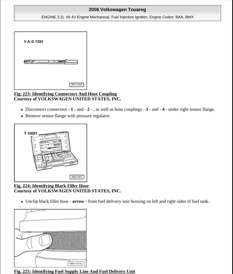
Fig. 223: Identifying Connectors And Hose Coupling Courtesy of VOLKSWAGEN UNITED STATES, INC.
Disconnect connectors - 1 - and - 2 - , as well as hose couplings - 3 - and - 4 - under right sensor flange.
Remove sensor flange with pressure regulator.
Fig. 224: Identifying Black Filler Hose Courtesy of VOLKSWAGEN UNITED STATES, INC.
Unclip black filler hose - arrow - from fuel delivery unit housing on left and right sides of fuel tank.
Fig. 225: Identifying Fuel Supply Line And Fuel Delivery Unit
2006 Volkswagen Touareg
ENGINE 3.2L V6 4V Engine Mechanical, Fuel Injection Ignition, Engine Codes: BAA, BMX
Microsoft
Sunday, September 20, 2009 9:14:19 AM Page 194 © 2005 Mitchell Repair Information Company, LLC.
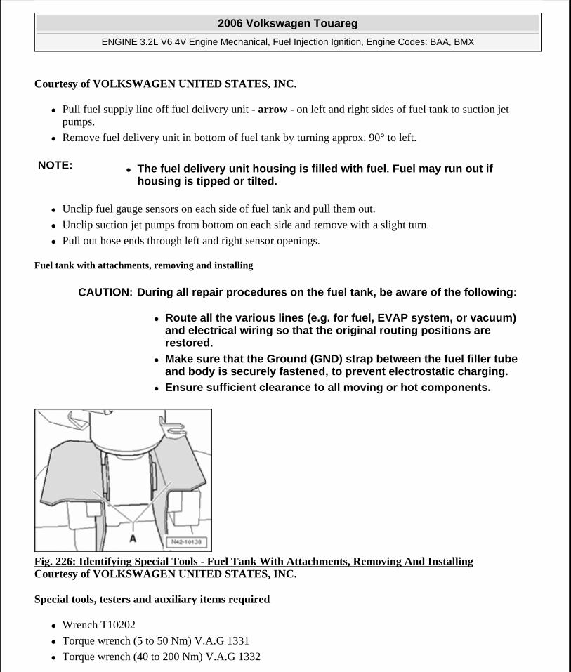
Courtesy of VOLKSWAGEN UNITED STATES, INC.
Pull fuel supply line off fuel delivery unit - arrow - on left and right sides of fuel tank to suction jet pumps.
Remove fuel delivery unit in bottom of fuel tank by turning approx. 90° to left.
Unclip fuel gauge sensors on each side of fuel tank and pull them out.
Unclip suction jet pumps from bottom on each side and remove with a slight turn.
Pull out hose ends through left and right sensor openings.
Fuel tank with attachments, removing and installing
Fig. 226: Identifying Special Tools - Fuel Tank With Attachments, Removing And Installing Courtesy of VOLKSWAGEN UNITED STATES, INC.
Special tools, testers and auxiliary items required
Wrench T10202
Torque wrench (5 to 50 Nm) V.A.G 1331
Torque wrench (40 to 200 Nm) V.A.G 1332
NOTE: The fuel delivery unit housing is filled with fuel. Fuel may run out if housing is tipped or tilted.
CAUTION: During all repair procedures on the fuel tank, be aware of the following:
Route all the various lines (e.g. for fuel, EVAP system, or vacuum) and electrical wiring so that the original routing positions are restored.
Make sure that the Ground (GND) strap between the fuel filler tube and body is securely fastened, to prevent electrostatic charging.
Ensure sufficient clearance to all moving or hot components.
2006 Volkswagen Touareg
ENGINE 3.2L V6 4V Engine Mechanical, Fuel Injection Ignition, Engine Codes: BAA, BMX
Microsoft
Sunday, September 20, 2009 9:14:19 AM Page 195 © 2005 Mitchell Repair Information Company, LLC.
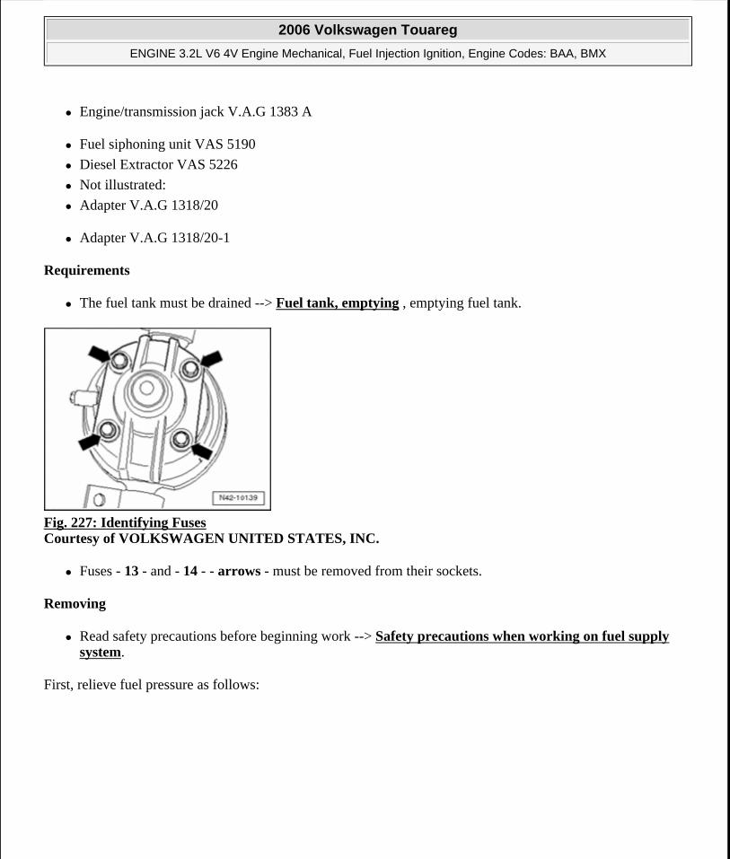
Engine/transmission jack V.A.G 1383 A
Fuel siphoning unit VAS 5190
Diesel Extractor VAS 5226
Not illustrated:
Adapter V.A.G 1318/20
Adapter V.A.G 1318/20-1
Requirements
The fuel tank must be drained --> Fuel tank, emptying , emptying fuel tank.
Fig. 227: Identifying Fuses Courtesy of VOLKSWAGEN UNITED STATES, INC.
Fuses - 13 - and - 14 - - arrows - must be removed from their sockets.
Removing
Read safety precautions before beginning work --> Safety precautions when working on fuel supply system.
First, relieve fuel pressure as follows:
2006 Volkswagen Touareg
ENGINE 3.2L V6 4V Engine Mechanical, Fuel Injection Ignition, Engine Codes: BAA, BMX
Microsoft
Sunday, September 20, 2009 9:14:19 AM Page 196 © 2005 Mitchell Repair Information Company, LLC.
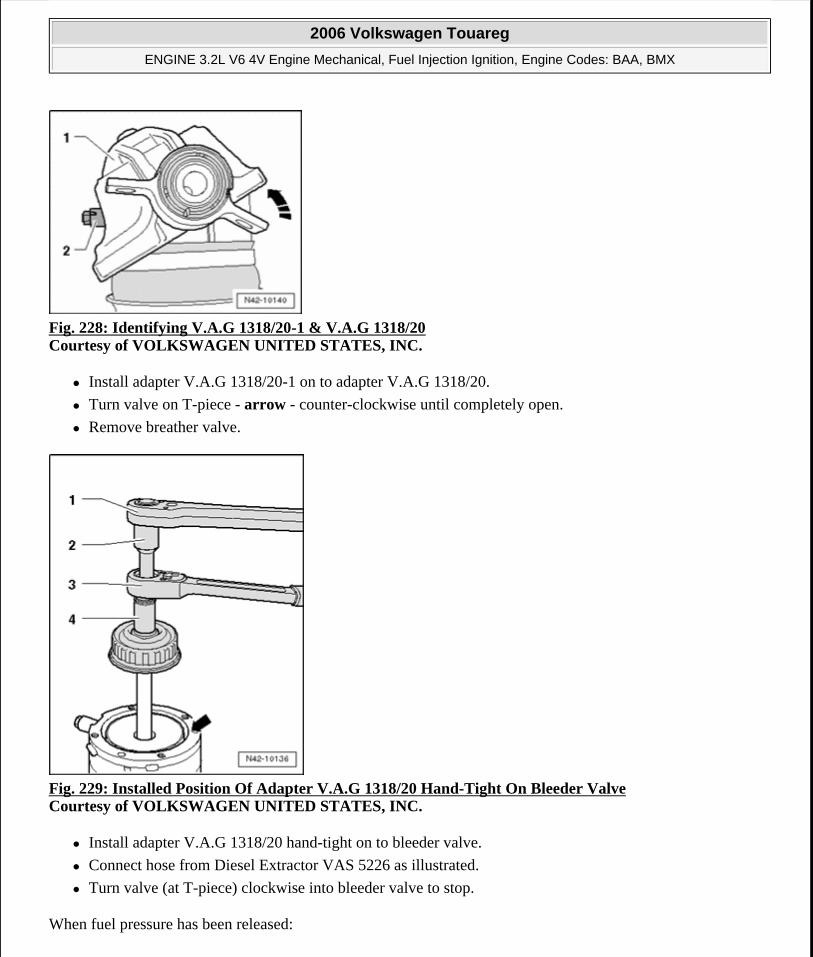
Fig. 228: Identifying V.A.G 1318/20-1 & V.A.G 1318/20 Courtesy of VOLKSWAGEN UNITED STATES, INC.
Install adapter V.A.G 1318/20-1 on to adapter V.A.G 1318/20.
Turn valve on T-piece - arrow - counter-clockwise until completely open.
Remove breather valve.
Fig. 229: Installed Position Of Adapter V.A.G 1318/20 Hand-Tight On Bleeder Valve Courtesy of VOLKSWAGEN UNITED STATES, INC.
Install adapter V.A.G 1318/20 hand-tight on to bleeder valve.
Connect hose from Diesel Extractor VAS 5226 as illustrated.
Turn valve (at T-piece) clockwise into bleeder valve to stop.
When fuel pressure has been released:
2006 Volkswagen Touareg
ENGINE 3.2L V6 4V Engine Mechanical, Fuel Injection Ignition, Engine Codes: BAA, BMX
Microsoft
Sunday, September 20, 2009 9:14:19 AM Page 197 © 2005 Mitchell Repair Information Company, LLC.
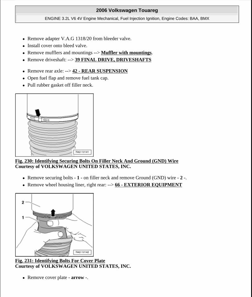
Remove adapter V.A.G 1318/20 from bleeder valve.
Install cover onto bleed valve.
Remove mufflers and mountings --> Muffler with mountings.
Remove driveshaft: --> 39 FINAL DRIVE, DRIVESHAFTS
Remove rear axle: --> 42 - REAR SUSPENSION
Open fuel flap and remove fuel tank cap.
Pull rubber gasket off filler neck.
Fig. 230: Identifying Securing Bolts On Filler Neck And Ground (GND) Wire Courtesy of VOLKSWAGEN UNITED STATES, INC.
Remove securing bolts - 1 - on filler neck and remove Ground (GND) wire - 2 -.
Remove wheel housing liner, right rear: --> 66 - EXTERIOR EQUIPMENT
Fig. 231: Identifying Bolts For Cover Plate Courtesy of VOLKSWAGEN UNITED STATES, INC.
Remove cover plate - arrow -.
2006 Volkswagen Touareg
ENGINE 3.2L V6 4V Engine Mechanical, Fuel Injection Ignition, Engine Codes: BAA, BMX
Microsoft
Sunday, September 20, 2009 9:14:19 AM Page 198 © 2005 Mitchell Repair Information Company, LLC.
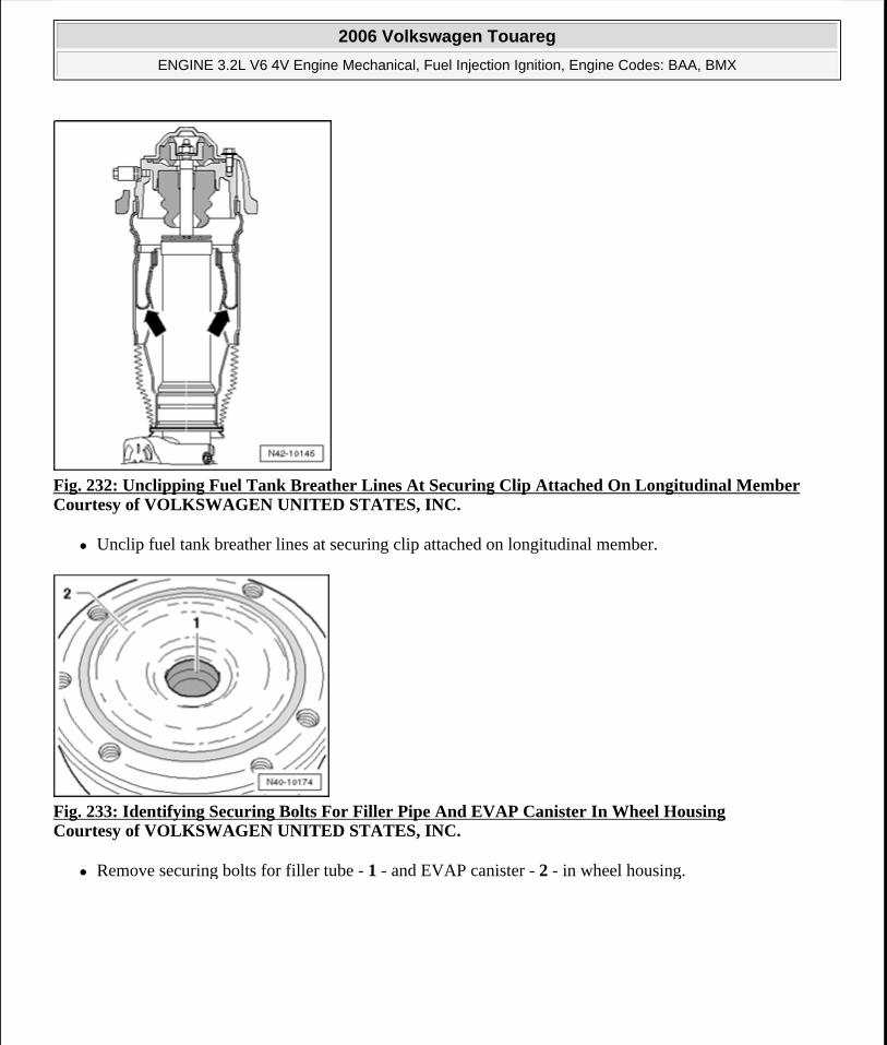
Fig. 232: Unclipping Fuel Tank Breather Lines At Securing Clip Attached On Longitudinal Member Courtesy of VOLKSWAGEN UNITED STATES, INC.
Unclip fuel tank breather lines at securing clip attached on longitudinal member.
Fig. 233: Identifying Securing Bolts For Filler Pipe And EVAP Canister In Wheel Housing Courtesy of VOLKSWAGEN UNITED STATES, INC.
Remove securing bolts for filler tube - 1 - and EVAP canister - 2 - in wheel housing.
2006 Volkswagen Touareg
ENGINE 3.2L V6 4V Engine Mechanical, Fuel Injection Ignition, Engine Codes: BAA, BMX
Microsoft
Sunday, September 20, 2009 9:14:19 AM Page 199 © 2005 Mitchell Repair Information Company, LLC.
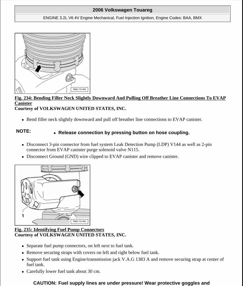
Fig. 234: Bending Filler Neck Slightly Downward And Pulling Off Breather Line Connections To EVAP Canister Courtesy of VOLKSWAGEN UNITED STATES, INC.
Bend filler neck slightly downward and pull off breather line connections to EVAP canister.
Disconnect 3-pin connector from fuel system Leak Detection Pump (LDP) V144 as well as 2-pin connector from EVAP canister purge solenoid valve N115.
Disconnect Ground (GND) wire clipped to EVAP canister and remove canister.
Fig. 235: Identifying Fuel Pump Connectors Courtesy of VOLKSWAGEN UNITED STATES, INC.
Separate fuel pump connectors, on left next to fuel tank.
Remove securing straps with covers on left and right below fuel tank.
Support fuel tank using Engine/transmission jack V.A.G 1383 A and remove securing strap at center of fuel tank.
Carefully lower fuel tank about 30 cm.
NOTE: Release connection by pressing button on hose coupling.
CAUTION: Fuel supply lines are under pressure! Wear protective goggles and
2006 Volkswagen Touareg
ENGINE 3.2L V6 4V Engine Mechanical, Fuel Injection Ignition, Engine Codes: BAA, BMX
Microsoft
Sunday, September 20, 2009 9:14:19 AM Page 200 © 2005 Mitchell Repair Information Company, LLC.
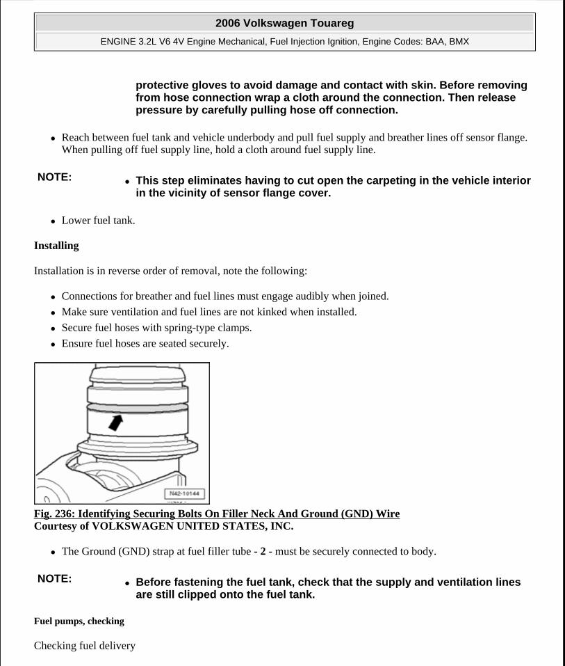
Reach between fuel tank and vehicle underbody and pull fuel supply and breather lines off sensor flange. When pulling off fuel supply line, hold a cloth around fuel supply line.
Lower fuel tank.
Installing
Installation is in reverse order of removal, note the following:
Connections for breather and fuel lines must engage audibly when joined.
Make sure ventilation and fuel lines are not kinked when installed.
Secure fuel hoses with spring-type clamps.
Ensure fuel hoses are seated securely.
Fig. 236: Identifying Securing Bolts On Filler Neck And Ground (GND) Wire Courtesy of VOLKSWAGEN UNITED STATES, INC.
The Ground (GND) strap at fuel filler tube - 2 - must be securely connected to body.
Fuel pumps, checking
Checking fuel delivery
protective gloves to avoid damage and contact with skin. Before removing from hose connection wrap a cloth around the connection. Then release pressure by carefully pulling hose off connection.
NOTE: This step eliminates having to cut open the carpeting in the vehicle interior in the vicinity of sensor flange cover.
NOTE: Before fastening the fuel tank, check that the supply and ventilation lines are still clipped onto the fuel tank.
2006 Volkswagen Touareg
ENGINE 3.2L V6 4V Engine Mechanical, Fuel Injection Ignition, Engine Codes: BAA, BMX
Microsoft
Sunday, September 20, 2009 9:14:19 AM Page 201 © 2005 Mitchell Repair Information Company, LLC.
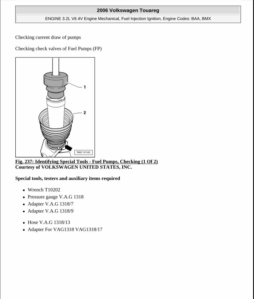
Checking current draw of pumps
Checking check valves of Fuel Pumps (FP)
Fig. 237: Identifying Special Tools - Fuel Pumps, Checking (1 Of 2) Courtesy of VOLKSWAGEN UNITED STATES, INC.
Special tools, testers and auxiliary items required
Wrench T10202
Pressure gauge V.A.G 1318
Adapter V.A.G 1318/7
Adapter V.A.G 1318/9
Hose V.A.G 1318/13
Adapter For VAG1318 VAG1318/17
2006 Volkswagen Touareg
ENGINE 3.2L V6 4V Engine Mechanical, Fuel Injection Ignition, Engine Codes: BAA, BMX
Microsoft
Sunday, September 20, 2009 9:14:19 AM Page 202 © 2005 Mitchell Repair Information Company, LLC.
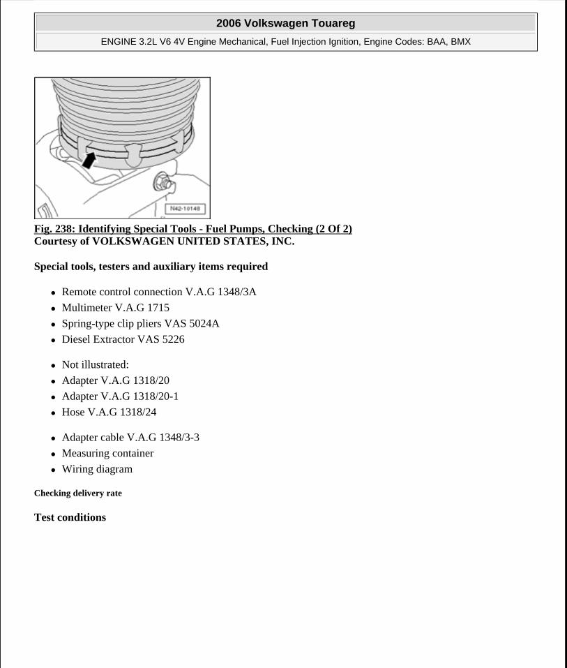
Fig. 238: Identifying Special Tools - Fuel Pumps, Checking (2 Of 2) Courtesy of VOLKSWAGEN UNITED STATES, INC.
Special tools, testers and auxiliary items required
Remote control connection V.A.G 1348/3A
Multimeter V.A.G 1715
Spring-type clip pliers VAS 5024A
Diesel Extractor VAS 5226
Not illustrated:
Adapter V.A.G 1318/20
Adapter V.A.G 1318/20-1
Hose V.A.G 1318/24
Adapter cable V.A.G 1348/3-3
Measuring container
Wiring diagram
Checking delivery rate
Test conditions
2006 Volkswagen Touareg
ENGINE 3.2L V6 4V Engine Mechanical, Fuel Injection Ignition, Engine Codes: BAA, BMX
Microsoft
Sunday, September 20, 2009 9:14:19 AM Page 203 © 2005 Mitchell Repair Information Company, LLC.
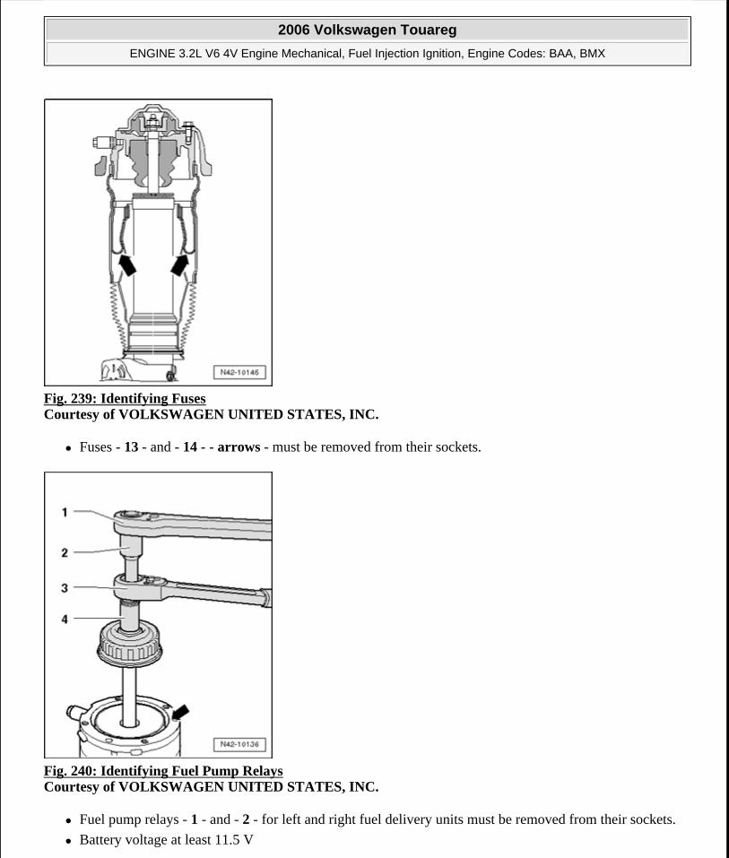
Fig. 239: Identifying Fuses Courtesy of VOLKSWAGEN UNITED STATES, INC.
Fuses - 13 - and - 14 - - arrows - must be removed from their sockets.
Fig. 240: Identifying Fuel Pump Relays Courtesy of VOLKSWAGEN UNITED STATES, INC.
Fuel pump relays - 1 - and - 2 - for left and right fuel delivery units must be removed from their sockets.
Battery voltage at least 11.5 V
2006 Volkswagen Touareg
ENGINE 3.2L V6 4V Engine Mechanical, Fuel Injection Ignition, Engine Codes: BAA, BMX
Microsoft
Sunday, September 20, 2009 9:14:19 AM Page 204 © 2005 Mitchell Repair Information Company, LLC.
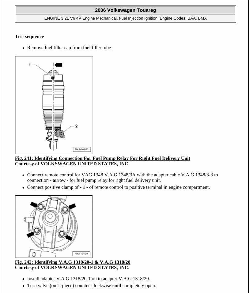
Test sequence
Remove fuel filler cap from fuel filler tube.
Fig. 241: Identifying Connection For Fuel Pump Relay For Right Fuel Delivery Unit Courtesy of VOLKSWAGEN UNITED STATES, INC.
Connect remote control for VAG 1348 V.A.G 1348/3A with the adapter cable V.A.G 1348/3-3 to connection - arrow - for fuel pump relay for right fuel delivery unit.
Connect positive clamp of - 1 - of remote control to positive terminal in engine compartment.
Fig. 242: Identifying V.A.G 1318/20-1 & V.A.G 1318/20 Courtesy of VOLKSWAGEN UNITED STATES, INC.
Install adapter V.A.G 1318/20-1 on to adapter V.A.G 1318/20.
Turn valve (on T-piece) counter-clockwise until completely open.
2006 Volkswagen Touareg
ENGINE 3.2L V6 4V Engine Mechanical, Fuel Injection Ignition, Engine Codes: BAA, BMX
Microsoft
Sunday, September 20, 2009 9:14:19 AM Page 205 © 2005 Mitchell Repair Information Company, LLC.
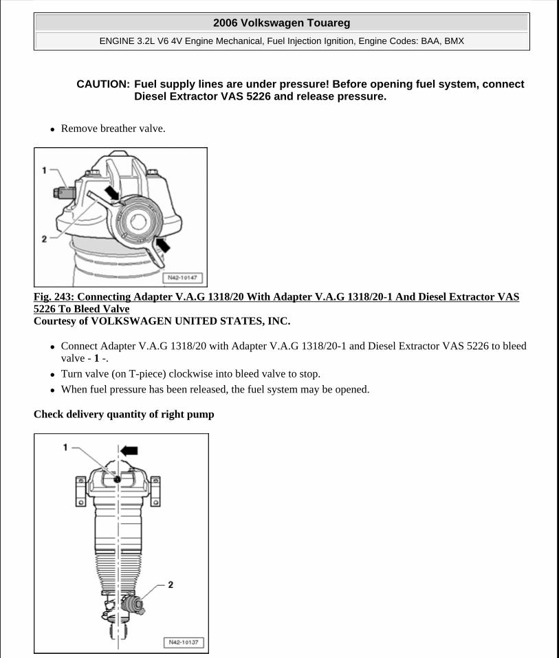
Remove breather valve.
Fig. 243: Connecting Adapter V.A.G 1318/20 With Adapter V.A.G 1318/20-1 And Diesel Extractor VAS 5226 To Bleed Valve Courtesy of VOLKSWAGEN UNITED STATES, INC.
Connect Adapter V.A.G 1318/20 with Adapter V.A.G 1318/20-1 and Diesel Extractor VAS 5226 to bleed valve - 1 -.
Turn valve (on T-piece) clockwise into bleed valve to stop.
When fuel pressure has been released, the fuel system may be opened.
Check delivery quantity of right pump
CAUTION: Fuel supply lines are under pressure! Before opening fuel system, connect Diesel Extractor VAS 5226 and release pressure.
2006 Volkswagen Touareg
ENGINE 3.2L V6 4V Engine Mechanical, Fuel Injection Ignition, Engine Codes: BAA, BMX
Microsoft
Sunday, September 20, 2009 9:14:19 AM Page 206 © 2005 Mitchell Repair Information Company, LLC.
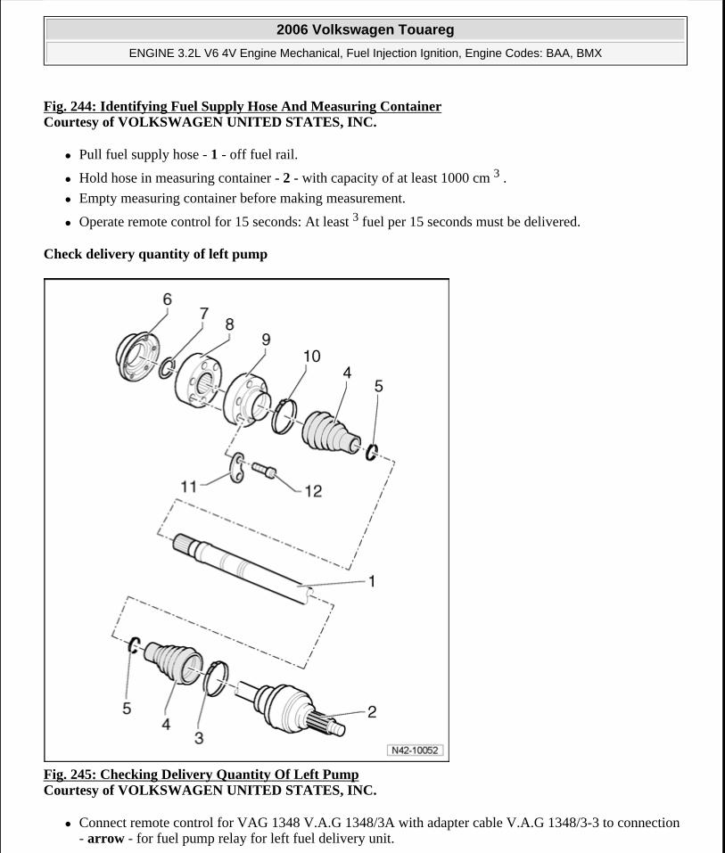
Fig. 244: Identifying Fuel Supply Hose And Measuring ContainerCourtesy of VOLKSWAGEN UNITED STATES, INC.
Pull fuel supply hose - 1 - off fuel rail.
Hold hose in measuring container - 2 - with capacity of at least 1000 cm 3 .
Empty measuring container before making measurement.
Operate remote control for 15 seconds: At least 3 fuel per 15 seconds must be delivered.
Check delivery quantity of left pump
Fig. 245: Checking Delivery Quantity Of Left Pump Courtesy of VOLKSWAGEN UNITED STATES, INC.
Connect remote control for VAG 1348 V.A.G 1348/3A with adapter cable V.A.G 1348/3-3 to connection - arrow - for fuel pump relay for left fuel delivery unit.
2006 Volkswagen Touareg
ENGINE 3.2L V6 4V Engine Mechanical, Fuel Injection Ignition, Engine Codes: BAA, BMX
Microsoft
Sunday, September 20, 2009 9:14:19 AM Page 207 © 2005 Mitchell Repair Information Company, LLC.
Empty measuring container before making measurement.
Operate remote control for 15 seconds again. At least 3 fuel per 15 seconds must be delivered.
Also test both fuel delivery units as follows:
Connect Adapter V.A.G 1348/3-3 to fuel pump relay connections for left and right fuel delivery units.
Operate remote control for 10 seconds: At least 800 cm 3 fuel per 10 seconds must be delivered.
If minimum delivery rate is not attained:
Check fuel lines for possible restrictions (kinks) or blockages.
If lines are OK:
Replace fuel filter:
If delivery rate has been attained but nevertheless you suspect a fuel supply system malfunction (e.g. intermittent failure of fuel supply system):
Check current consumption of fuel pumps.
Current draw of pumps, checking
Check current draw of each individual Fuel Pump (FP) as follows:
Reconnect all disconnected fuel lines.
2006 Volkswagen Touareg
ENGINE 3.2L V6 4V Engine Mechanical, Fuel Injection Ignition, Engine Codes: BAA, BMX
Microsoft
Sunday, September 20, 2009 9:14:19 AM Page 208 © 2005 Mitchell Repair Information Company, LLC.
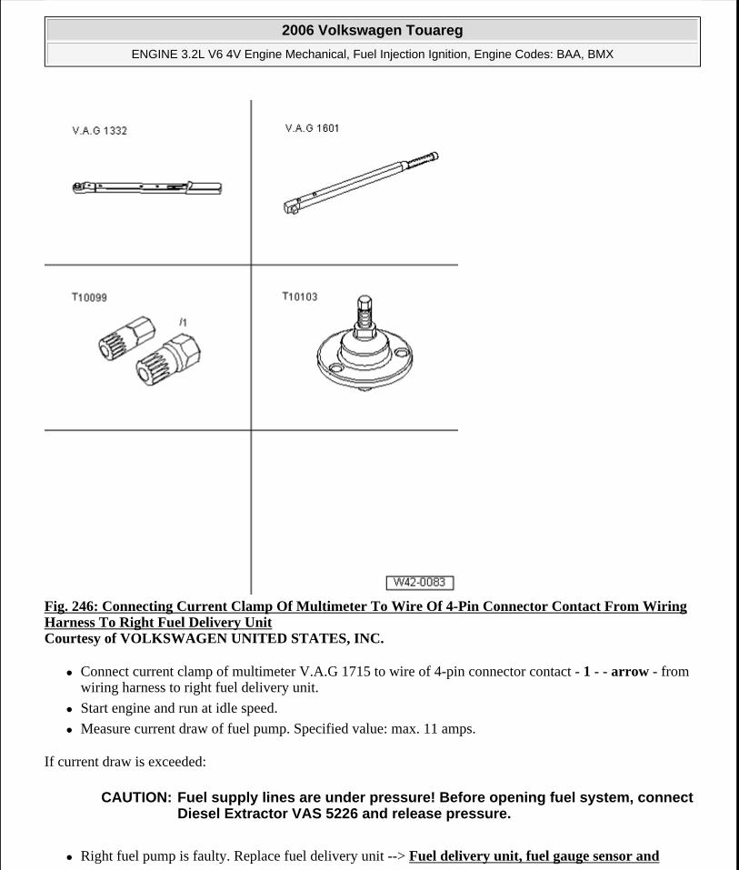
Fig. 246: Connecting Current Clamp Of Multimeter To Wire Of 4-Pin Connector Contact From Wiring Harness To Right Fuel Delivery Unit Courtesy of VOLKSWAGEN UNITED STATES, INC.
Connect current clamp of multimeter V.A.G 1715 to wire of 4-pin connector contact - 1 - - arrow - from wiring harness to right fuel delivery unit.
Start engine and run at idle speed.
Measure current draw of fuel pump. Specified value: max. 11 amps.
If current draw is exceeded:
Right fuel pump is faulty. Replace fuel delivery unit --> Fuel delivery unit, fuel gauge sensor and
CAUTION: Fuel supply lines are under pressure! Before opening fuel system, connect Diesel Extractor VAS 5226 and release pressure.
2006 Volkswagen Touareg
ENGINE 3.2L V6 4V Engine Mechanical, Fuel Injection Ignition, Engine Codes: BAA, BMX
Microsoft
Sunday, September 20, 2009 9:14:19 AM Page 209 © 2005 Mitchell Repair Information Company, LLC.
suction jet pump, removing and installing.
Repeat test on left fuel delivery unit.
If current draw is exceeded:
Left Fuel Pump (FP) malfunctioning, replace fuel pump unit --> Fuel delivery unit, fuel gauge sensor and suction jet pump, removing and installing.
Check valves of Fuel Pumps (FP), checking
Conditions
Remote control for VAG 1348 V.A.G 1348/3A is still connected.
Test sequence
Turn valve on T-piece of adapter V.A.G 1318/20 counter-clockwise until completely open.
NOTE: If malfunction in fuel system is sporadic, test can also be performed during a road test, but a second person is required.
NOTE: With this check, the fuel supply line connections from the fuel delivery units to the point at which pressure gauge V.A.G 1318 is connected will be checked for leaks at the same time.
2006 Volkswagen Touareg
ENGINE 3.2L V6 4V Engine Mechanical, Fuel Injection Ignition, Engine Codes: BAA, BMX
Microsoft
Sunday, September 20, 2009 9:14:19 AM Page 210 © 2005 Mitchell Repair Information Company, LLC.
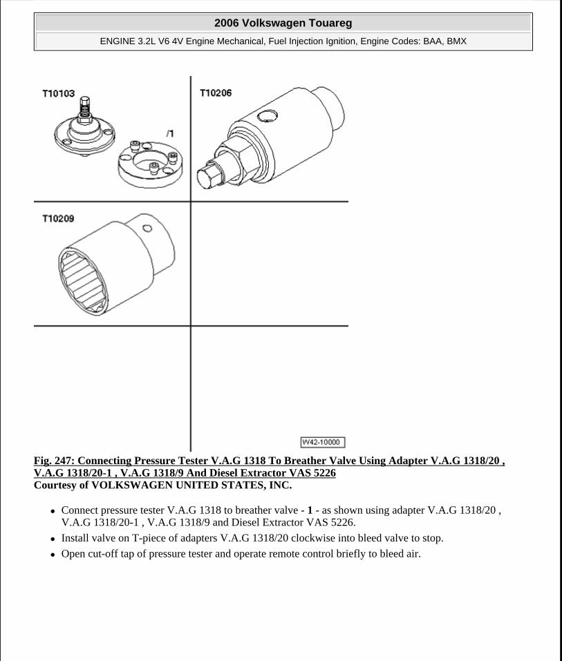
Fig. 247: Connecting Pressure Tester V.A.G 1318 To Breather Valve Using Adapter V.A.G 1318/20 , V.A.G 1318/20-1 , V.A.G 1318/9 And Diesel Extractor VAS 5226 Courtesy of VOLKSWAGEN UNITED STATES, INC.
Connect pressure tester V.A.G 1318 to breather valve - 1 - as shown using adapter V.A.G 1318/20 , V.A.G 1318/20-1 , V.A.G 1318/9 and Diesel Extractor VAS 5226.
Install valve on T-piece of adapters V.A.G 1318/20 clockwise into bleed valve to stop.
Open cut-off tap of pressure tester and operate remote control briefly to bleed air.
2006 Volkswagen Touareg
ENGINE 3.2L V6 4V Engine Mechanical, Fuel Injection Ignition, Engine Codes: BAA, BMX
Microsoft
Sunday, September 20, 2009 9:14:19 AM Page 211 © 2005 Mitchell Repair Information Company, LLC.
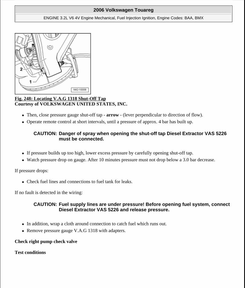
Fig. 248: Locating V.A.G 1318 Shut-Off Tap Courtesy of VOLKSWAGEN UNITED STATES, INC.
Then, close pressure gauge shut-off tap - arrow - (lever perpendicular to direction of flow).
Operate remote control at short intervals, until a pressure of approx. 4 bar has built up.
If pressure builds up too high, lower excess pressure by carefully opening shut-off tap.
Watch pressure drop on gauge. After 10 minutes pressure must not drop below a 3.0 bar decrease.
If pressure drops:
Check fuel lines and connections to fuel tank for leaks.
If no fault is detected in the wiring:
In addition, wrap a cloth around connection to catch fuel which runs out.
Remove pressure gauge V.A.G 1318 with adapters.
Check right pump check valve
Test conditions
CAUTION: Danger of spray when opening the shut-off tap Diesel Extractor VAS 5226 must be connected.
CAUTION: Fuel supply lines are under pressure! Before opening fuel system, connect Diesel Extractor VAS 5226 and release pressure.
2006 Volkswagen Touareg
ENGINE 3.2L V6 4V Engine Mechanical, Fuel Injection Ignition, Engine Codes: BAA, BMX
Microsoft
Sunday, September 20, 2009 9:14:19 AM Page 212 © 2005 Mitchell Repair Information Company, LLC.
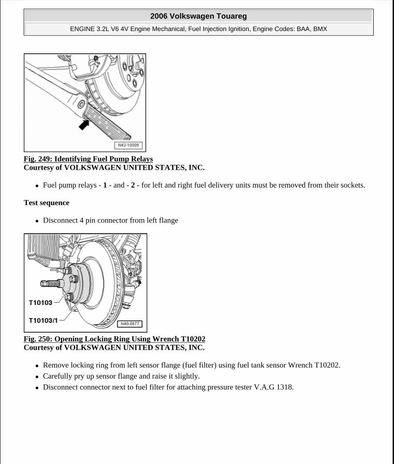
Fig. 249: Identifying Fuel Pump Relays Courtesy of VOLKSWAGEN UNITED STATES, INC.
Fuel pump relays - 1 - and - 2 - for left and right fuel delivery units must be removed from their sockets.
Test sequence
Disconnect 4 pin connector from left flange
Fig. 250: Opening Locking Ring Using Wrench T10202 Courtesy of VOLKSWAGEN UNITED STATES, INC.
Remove locking ring from left sensor flange (fuel filter) using fuel tank sensor Wrench T10202.
Carefully pry up sensor flange and raise it slightly.
Disconnect connector next to fuel filter for attaching pressure tester V.A.G 1318.
2006 Volkswagen Touareg
ENGINE 3.2L V6 4V Engine Mechanical, Fuel Injection Ignition, Engine Codes: BAA, BMX
Microsoft
Sunday, September 20, 2009 9:14:19 AM Page 213 © 2005 Mitchell Repair Information Company, LLC.
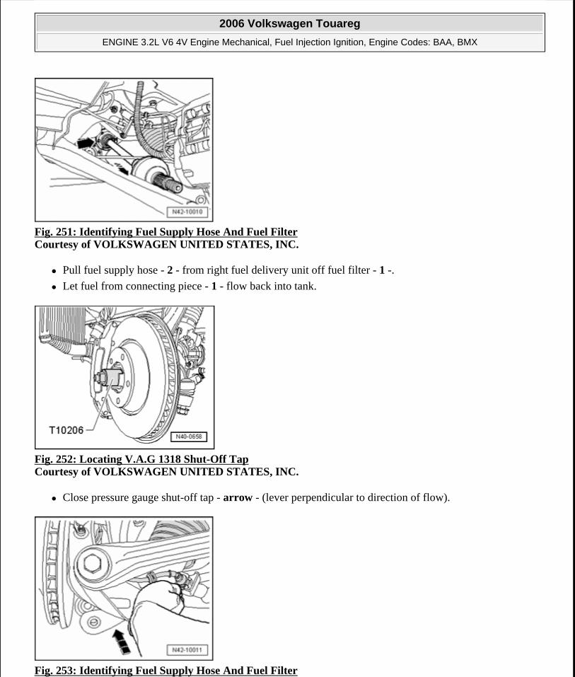
Fig. 251: Identifying Fuel Supply Hose And Fuel Filter Courtesy of VOLKSWAGEN UNITED STATES, INC.
Pull fuel supply hose - 2 - from right fuel delivery unit off fuel filter - 1 -.
Let fuel from connecting piece - 1 - flow back into tank.
Fig. 252: Locating V.A.G 1318 Shut-Off Tap Courtesy of VOLKSWAGEN UNITED STATES, INC.
Close pressure gauge shut-off tap - arrow - (lever perpendicular to direction of flow).
Fig. 253: Identifying Fuel Supply Hose And Fuel Filter
2006 Volkswagen Touareg
ENGINE 3.2L V6 4V Engine Mechanical, Fuel Injection Ignition, Engine Codes: BAA, BMX
Microsoft
Sunday, September 20, 2009 9:14:19 AM Page 214 © 2005 Mitchell Repair Information Company, LLC.
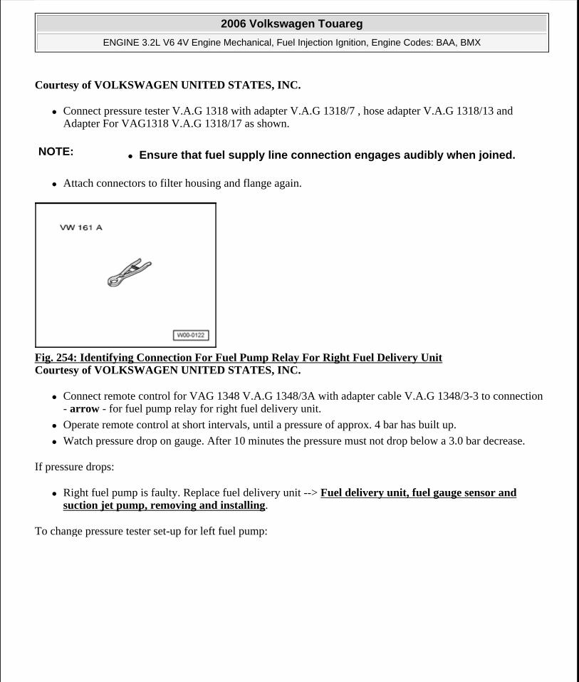
Courtesy of VOLKSWAGEN UNITED STATES, INC.
Connect pressure tester V.A.G 1318 with adapter V.A.G 1318/7 , hose adapter V.A.G 1318/13 and Adapter For VAG1318 V.A.G 1318/17 as shown.
Attach connectors to filter housing and flange again.
Fig. 254: Identifying Connection For Fuel Pump Relay For Right Fuel Delivery Unit Courtesy of VOLKSWAGEN UNITED STATES, INC.
Connect remote control for VAG 1348 V.A.G 1348/3A with adapter cable V.A.G 1348/3-3 to connection - arrow - for fuel pump relay for right fuel delivery unit.
Operate remote control at short intervals, until a pressure of approx. 4 bar has built up.
Watch pressure drop on gauge. After 10 minutes the pressure must not drop below a 3.0 bar decrease.
If pressure drops:
Right fuel pump is faulty. Replace fuel delivery unit --> Fuel delivery unit, fuel gauge sensor and suction jet pump, removing and installing.
To change pressure tester set-up for left fuel pump:
NOTE: Ensure that fuel supply line connection engages audibly when joined.
2006 Volkswagen Touareg
ENGINE 3.2L V6 4V Engine Mechanical, Fuel Injection Ignition, Engine Codes: BAA, BMX
Microsoft
Sunday, September 20, 2009 9:14:19 AM Page 215 © 2005 Mitchell Repair Information Company, LLC.
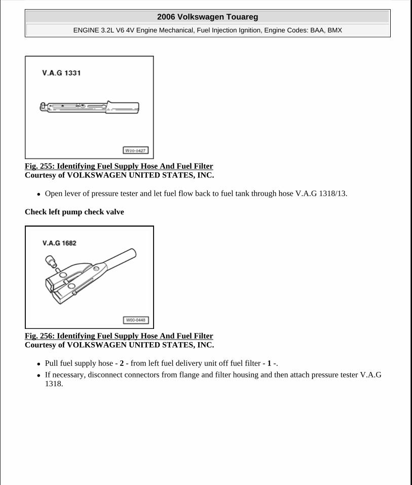
Fig. 255: Identifying Fuel Supply Hose And Fuel Filter Courtesy of VOLKSWAGEN UNITED STATES, INC.
Open lever of pressure tester and let fuel flow back to fuel tank through hose V.A.G 1318/13.
Check left pump check valve
Fig. 256: Identifying Fuel Supply Hose And Fuel Filter Courtesy of VOLKSWAGEN UNITED STATES, INC.
Pull fuel supply hose - 2 - from left fuel delivery unit off fuel filter - 1 -.
If necessary, disconnect connectors from flange and filter housing and then attach pressure tester V.A.G 1318.
2006 Volkswagen Touareg
ENGINE 3.2L V6 4V Engine Mechanical, Fuel Injection Ignition, Engine Codes: BAA, BMX
Microsoft
Sunday, September 20, 2009 9:14:19 AM Page 216 © 2005 Mitchell Repair Information Company, LLC.
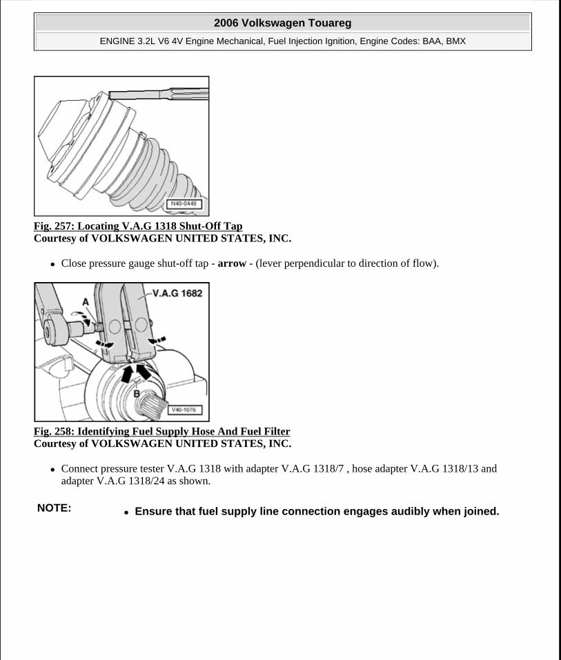
Fig. 257: Locating V.A.G 1318 Shut-Off Tap Courtesy of VOLKSWAGEN UNITED STATES, INC.
Close pressure gauge shut-off tap - arrow - (lever perpendicular to direction of flow).
Fig. 258: Identifying Fuel Supply Hose And Fuel Filter Courtesy of VOLKSWAGEN UNITED STATES, INC.
Connect pressure tester V.A.G 1318 with adapter V.A.G 1318/7 , hose adapter V.A.G 1318/13 and adapter V.A.G 1318/24 as shown.
NOTE: Ensure that fuel supply line connection engages audibly when joined.
2006 Volkswagen Touareg
ENGINE 3.2L V6 4V Engine Mechanical, Fuel Injection Ignition, Engine Codes: BAA, BMX
Microsoft
Sunday, September 20, 2009 9:14:19 AM Page 217 © 2005 Mitchell Repair Information Company, LLC.
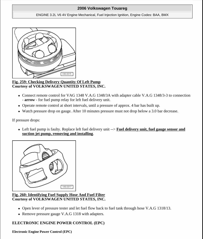
Fig. 259: Checking Delivery Quantity Of Left Pump Courtesy of VOLKSWAGEN UNITED STATES, INC.
Connect remote control for VAG 1348 V.A.G 1348/3A with adapter cable V.A.G 1348/3-3 to connection - arrow - for fuel pump relay for left fuel delivery unit.
Operate remote control at short intervals, until a pressure of approx. 4 bar has built up.
Watch pressure drop on gauge. After 10 minutes pressure must not drop below a 3.0 bar decrease.
If pressure drops:
Left fuel pump is faulty. Replace left fuel delivery unit --> Fuel delivery unit, fuel gauge sensor and suction jet pump, removing and installing.
Fig. 260: Identifying Fuel Supply Hose And Fuel Filter Courtesy of VOLKSWAGEN UNITED STATES, INC.
Open lever of pressure tester and let fuel flow back to fuel tank through hose V.A.G 1318/13.
Remove pressure gauge V.A.G 1318 with adapters.
ELECTRONIC ENGINE POWER CONTROL (EPC)
Electronic Engine Power Control (EPC)
2006 Volkswagen Touareg
ENGINE 3.2L V6 4V Engine Mechanical, Fuel Injection Ignition, Engine Codes: BAA, BMX
Microsoft
Sunday, September 20, 2009 9:14:19 AM Page 218 © 2005 Mitchell Repair Information Company, LLC.
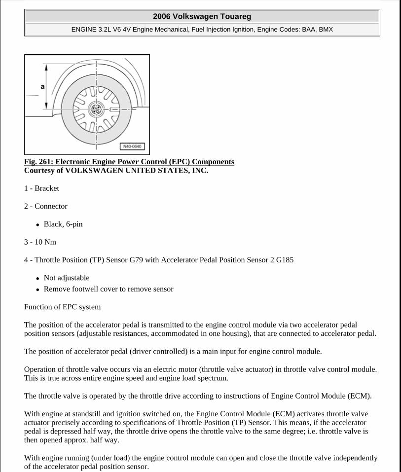
Fig. 261: Electronic Engine Power Control (EPC) Components Courtesy of VOLKSWAGEN UNITED STATES, INC.
1 - Bracket
2 - Connector
Black, 6-pin
3 - 10 Nm
4 - Throttle Position (TP) Sensor G79 with Accelerator Pedal Position Sensor 2 G185
Not adjustable
Remove footwell cover to remove sensor
Function of EPC system
The position of the accelerator pedal is transmitted to the engine control module via two accelerator pedal position sensors (adjustable resistances, accommodated in one housing), that are connected to accelerator pedal.
The position of accelerator pedal (driver controlled) is a main input for engine control module.
Operation of throttle valve occurs via an electric motor (throttle valve actuator) in throttle valve control module. This is true across entire engine speed and engine load spectrum.
The throttle valve is operated by the throttle drive according to instructions of Engine Control Module (ECM).
With engine at standstill and ignition switched on, the Engine Control Module (ECM) activates throttle valve actuator precisely according to specifications of Throttle Position (TP) Sensor. This means, if the accelerator pedal is depressed half way, the throttle drive opens the throttle valve to the same degree; i.e. throttle valve is then opened approx. half way.
With engine running (under load) the engine control module can open and close the throttle valve independently of the accelerator pedal position sensor.
2006 Volkswagen Touareg
ENGINE 3.2L V6 4V Engine Mechanical, Fuel Injection Ignition, Engine Codes: BAA, BMX
Microsoft
Sunday, September 20, 2009 9:14:19 AM Page 219 © 2005 Mitchell Repair Information Company, LLC.
That way e.g. the throttle valve can already be completely opened, although accelerator pedal is only depressed half-way. An advantage of this is that throttle losses at throttle valve are avoided.
Aside from that, it results in clearly better pollutant output and consumption values under certain load conditions.
According to torque requirement outputs from the various components (e.g. air conditioning, automatic transmission, ABS/ESP...), the engine control module calculates a throttle valve open angle that is optimal for a respective situation.
Observe safety precautions --> Safety precautions when working on fuel supply system.
Observe rules for cleanliness --> Rules for cleanliness.
EVAPORATIVE EMISSION (EVAP) CANISTER PURGE SOLENOID VALVE SYSTEM
Evaporative emission (EVAP) canister purge solenoid valve system
EVAP canister system components, assembly overview --> Evaporative emission (EVAP) canister purge solenoid valve system, assembly overview
Checking fuel supply system for leaks --> Evaporative Emission (EVAP) Canister Purge Regulator Valve N80 system, checking for leaks
Function
Depending on air pressure and ambient temperature, varying quantities of fuel vapors form above fuel surface in fuel tank.
The EVAP canister system prevents these HC emissions from entering the atmosphere.
Fuel vapors travel from the highest point of the fuel tank (at filler tube) via expansion tank into EVAP canister.
The activated charcoal in canister stores these gases like a sponge.
While driving, with oxygen sensor control active (engine warm), the Evaporative Emission (EVAP) Canister Purge Regulator Valve N80 is activated by Engine Control Module (ECM) J623 in pulses dependent on load and engine speed. The opening time is dependent on input signals.
During cleansing process (regeneration of active charcoal), intake manifold vacuum sucks fresh air through breather connection of the EVAP canister. The fuel vapors stored amongst activated charcoal and fresh air are proportionately supplied to be burned.
Evaporative Emission (EVAP) Canister Purge Regulator Valve N80 is closed without current (e.g. open circuit). The EVAP canister is not purged.
Function description of leak diagnosis
2006 Volkswagen Touareg
ENGINE 3.2L V6 4V Engine Mechanical, Fuel Injection Ignition, Engine Codes: BAA, BMX
Microsoft
Sunday, September 20, 2009 9:14:19 AM Page 220 © 2005 Mitchell Repair Information Company, LLC.
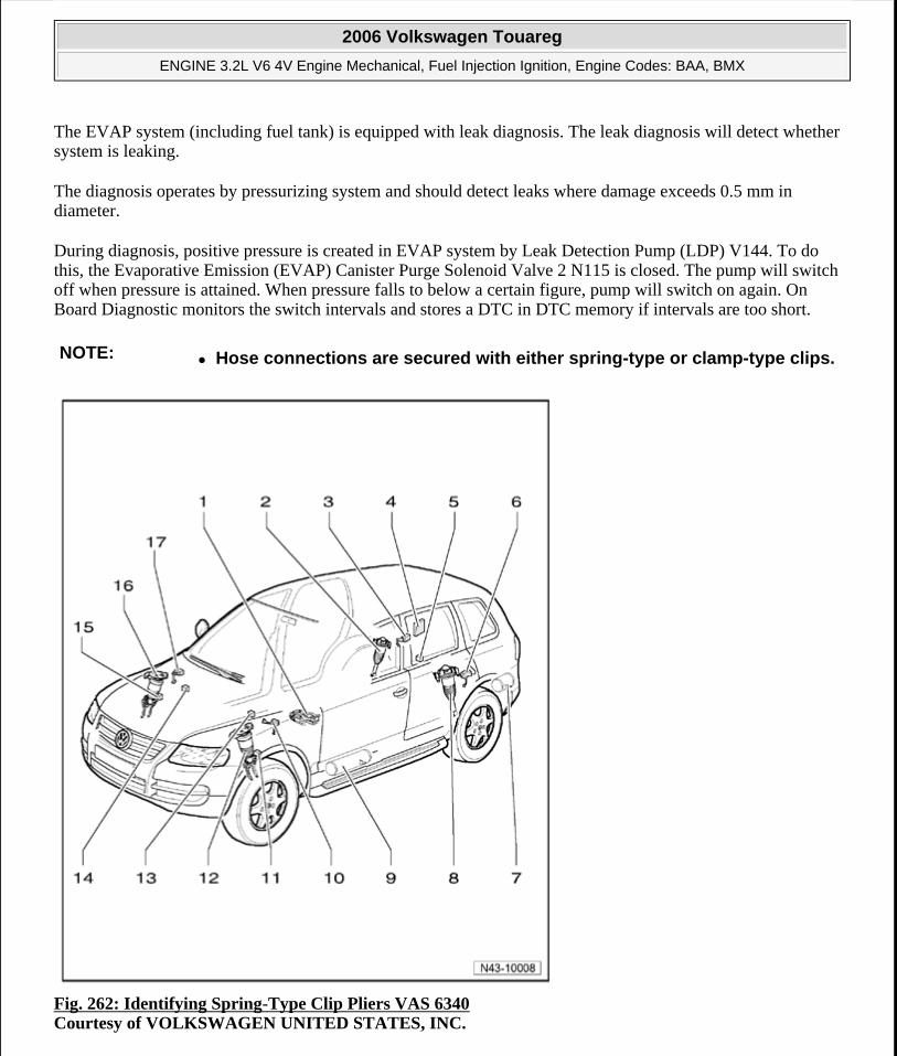
The EVAP system (including fuel tank) is equipped with leak diagnosis. The leak diagnosis will detect whether system is leaking.
The diagnosis operates by pressurizing system and should detect leaks where damage exceeds 0.5 mm in diameter.
During diagnosis, positive pressure is created in EVAP system by Leak Detection Pump (LDP) V144. To do this, the Evaporative Emission (EVAP) Canister Purge Solenoid Valve 2 N115 is closed. The pump will switch off when pressure is attained. When pressure falls to below a certain figure, pump will switch on again. On Board Diagnostic monitors the switch intervals and stores a DTC in DTC memory if intervals are too short.
Fig. 262: Identifying Spring-Type Clip Pliers VAS 6340 Courtesy of VOLKSWAGEN UNITED STATES, INC.
NOTE: Hose connections are secured with either spring-type or clamp-type clips.
2006 Volkswagen Touareg
ENGINE 3.2L V6 4V Engine Mechanical, Fuel Injection Ignition, Engine Codes: BAA, BMX
Microsoft
Sunday, September 20, 2009 9:14:19 AM Page 221 © 2005 Mitchell Repair Information Company, LLC.
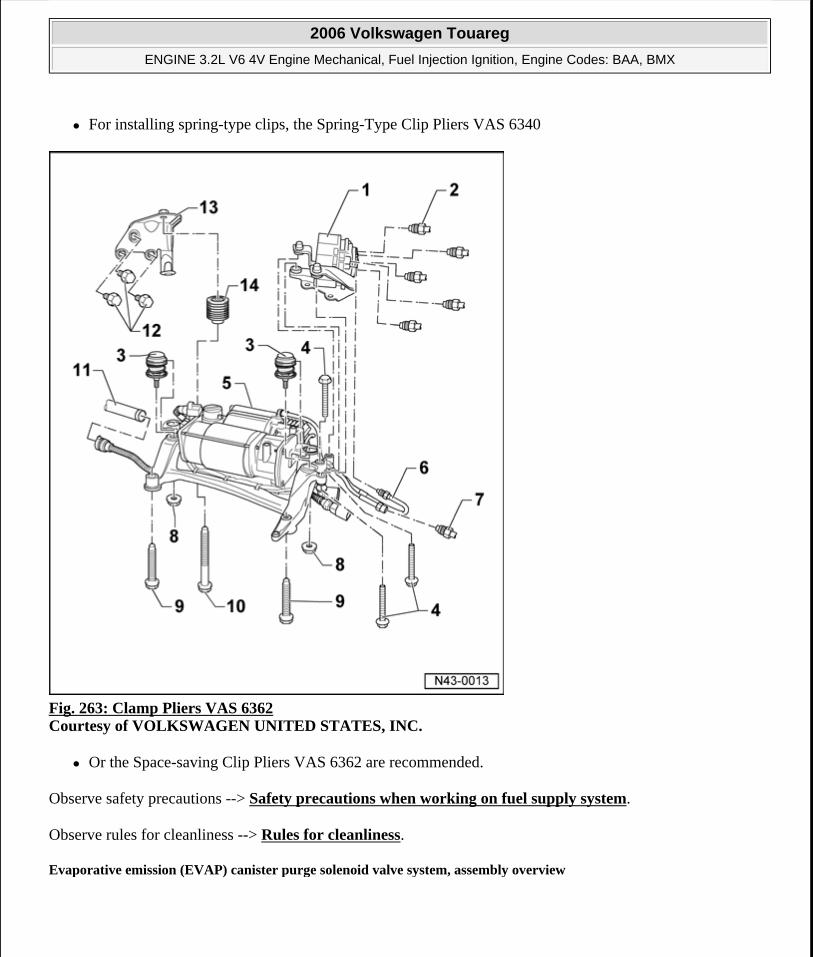
For installing spring-type clips, the Spring-Type Clip Pliers VAS 6340
Fig. 263: Clamp Pliers VAS 6362 Courtesy of VOLKSWAGEN UNITED STATES, INC.
Or the Space-saving Clip Pliers VAS 6362 are recommended.
Observe safety precautions --> Safety precautions when working on fuel supply system.
Observe rules for cleanliness --> Rules for cleanliness.
Evaporative emission (EVAP) canister purge solenoid valve system, assembly overview
2006 Volkswagen Touareg
ENGINE 3.2L V6 4V Engine Mechanical, Fuel Injection Ignition, Engine Codes: BAA, BMX
Microsoft
Sunday, September 20, 2009 9:14:19 AM Page 222 © 2005 Mitchell Repair Information Company, LLC.
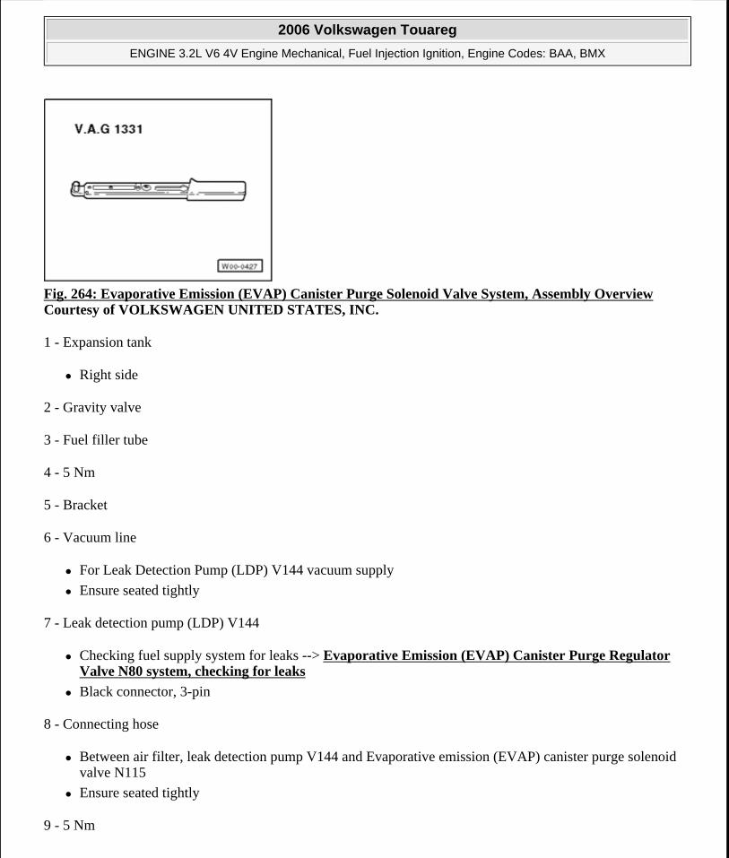
Fig. 264: Evaporative Emission (EVAP) Canister Purge Solenoid Valve System, Assembly Overview Courtesy of VOLKSWAGEN UNITED STATES, INC.
1 - Expansion tank
Right side
2 - Gravity valve
3 - Fuel filler tube
4 - 5 Nm
5 - Bracket
6 - Vacuum line
For Leak Detection Pump (LDP) V144 vacuum supply
Ensure seated tightly
7 - Leak detection pump (LDP) V144
Checking fuel supply system for leaks --> Evaporative Emission (EVAP) Canister Purge Regulator Valve N80 system, checking for leaks
Black connector, 3-pin
8 - Connecting hose
Between air filter, leak detection pump V144 and Evaporative emission (EVAP) canister purge solenoid valve N115
Ensure seated tightly
9 - 5 Nm
2006 Volkswagen Touareg
ENGINE 3.2L V6 4V Engine Mechanical, Fuel Injection Ignition, Engine Codes: BAA, BMX
Microsoft
Sunday, September 20, 2009 9:14:19 AM Page 223 © 2005 Mitchell Repair Information Company, LLC.
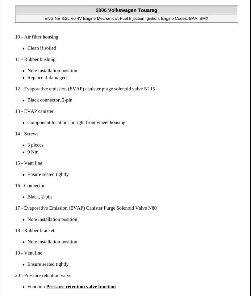
10 - Air filter housing
Clean if soiled
11 - Rubber bushing
Note installation position
Replace if damaged
12 - Evaporative emission (EVAP) canister purge solenoid valve N115
Black connector, 2-pin
13 - EVAP canister
Component location: In right front wheel housing
14 - Screws
3 pieces
9 Nm
15 - Vent line
Ensure seated tightly
16 - Connector
Black, 2-pin
17 - Evaporative Emission (EVAP) Canister Purge Solenoid Valve N80
Note installation position
18 - Rubber bracket
Note installation position
19 - Vent line
Ensure seated tightly
20 - Pressure retention valve
Function Pressure retention valve function
2006 Volkswagen Touareg
ENGINE 3.2L V6 4V Engine Mechanical, Fuel Injection Ignition, Engine Codes: BAA, BMX
Microsoft
Sunday, September 20, 2009 9:14:19 AM Page 224 © 2005 Mitchell Repair Information Company, LLC.
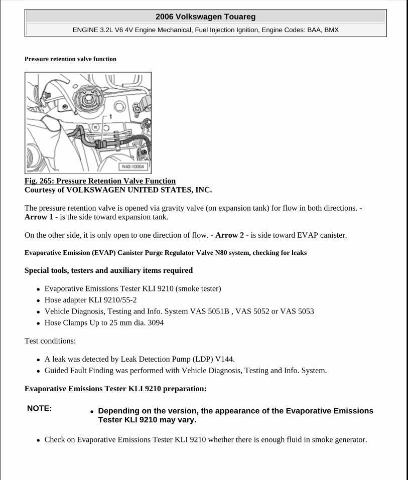
Pressure retention valve function
Fig. 265: Pressure Retention Valve Function Courtesy of VOLKSWAGEN UNITED STATES, INC.
The pressure retention valve is opened via gravity valve (on expansion tank) for flow in both directions. - Arrow 1 - is the side toward expansion tank.
On the other side, it is only open to one direction of flow. - Arrow 2 - is side toward EVAP canister.
Evaporative Emission (EVAP) Canister Purge Regulator Valve N80 system, checking for leaks
Special tools, testers and auxiliary items required
Evaporative Emissions Tester KLI 9210 (smoke tester)
Hose adapter KLI 9210/55-2
Vehicle Diagnosis, Testing and Info. System VAS 5051B , VAS 5052 or VAS 5053
Hose Clamps Up to 25 mm dia. 3094
Test conditions:
A leak was detected by Leak Detection Pump (LDP) V144.
Guided Fault Finding was performed with Vehicle Diagnosis, Testing and Info. System.
Evaporative Emissions Tester KLI 9210 preparation:
Check on Evaporative Emissions Tester KLI 9210 whether there is enough fluid in smoke generator.
NOTE: Depending on the version, the appearance of the Evaporative Emissions Tester KLI 9210 may vary.
2006 Volkswagen Touareg
ENGINE 3.2L V6 4V Engine Mechanical, Fuel Injection Ignition, Engine Codes: BAA, BMX
Microsoft
Sunday, September 20, 2009 9:14:19 AM Page 225 © 2005 Mitchell Repair Information Company, LLC.
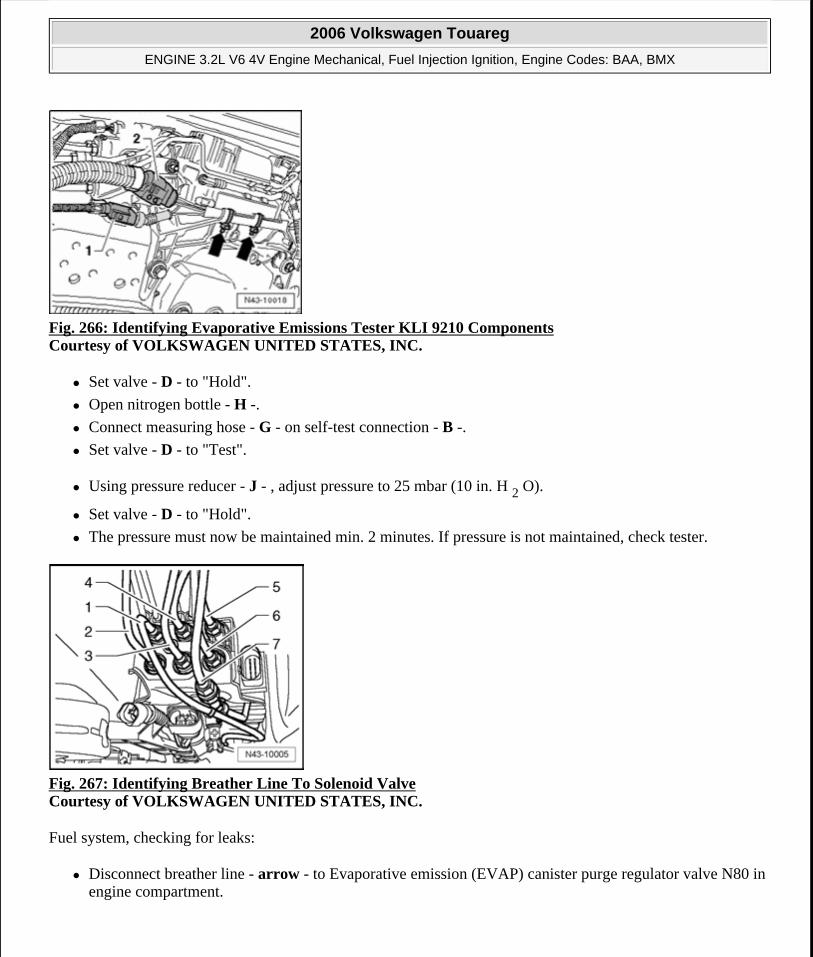
Fig. 266: Identifying Evaporative Emissions Tester KLI 9210 Components Courtesy of VOLKSWAGEN UNITED STATES, INC.
Set valve - D - to "Hold".
Open nitrogen bottle - H -.
Connect measuring hose - G - on self-test connection - B -.
Set valve - D - to "Test".
Using pressure reducer - J - , adjust pressure to 25 mbar (10 in. H 2 O).
Set valve - D - to "Hold".
The pressure must now be maintained min. 2 minutes. If pressure is not maintained, check tester.
Fig. 267: Identifying Breather Line To Solenoid Valve Courtesy of VOLKSWAGEN UNITED STATES, INC.
Fuel system, checking for leaks:
Disconnect breather line - arrow - to Evaporative emission (EVAP) canister purge regulator valve N80 in engine compartment.
2006 Volkswagen Touareg
ENGINE 3.2L V6 4V Engine Mechanical, Fuel Injection Ignition, Engine Codes: BAA, BMX
Microsoft
Sunday, September 20, 2009 9:14:19 AM Page 226 © 2005 Mitchell Repair Information Company, LLC.
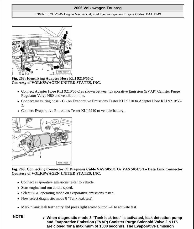
Fig. 268: Identifying Adapter Hose KLI 9210/55-2 Courtesy of VOLKSWAGEN UNITED STATES, INC.
Connect Adapter Hose KLI 9210/55-2 as shown between Evaporative Emission (EVAP) Canister Purge Regulator Valve N80 and ventilation line.
Connect measuring hose - G - on Evaporative Emissions Tester KLI 9210 to Adapter Hose KLI 9210/55-2.
Connect Evaporative Emissions Tester KLI 9210 to vehicle battery.
Fig. 269: Connecting Connector Of Diagnosis Cable VAS 5051/1 Or VAS 5051/3 To Data Link ConnectorCourtesy of VOLKSWAGEN UNITED STATES, INC.
Connect evaporative emissions tester to vehicle.
Start engine and run at idle speed.
Select OBD operating mode on evaporative emissions tester.
Now select diagnostic mode 8 "Tank leak test".
Mark "Tank leak test" entry and press right arrow button --> to activate test.
NOTE: When diagnostic mode 8 "Tank leak test" is activated, leak detection pump and Evaporative Emission (EVAP) Canister Purge Solenoid Valve 2 N115 are closed for a maximum of 1000 seconds. The Evaporative Emission
2006 Volkswagen Touareg
ENGINE 3.2L V6 4V Engine Mechanical, Fuel Injection Ignition, Engine Codes: BAA, BMX
Microsoft
Sunday, September 20, 2009 9:14:19 AM Page 227 © 2005 Mitchell Repair Information Company, LLC.
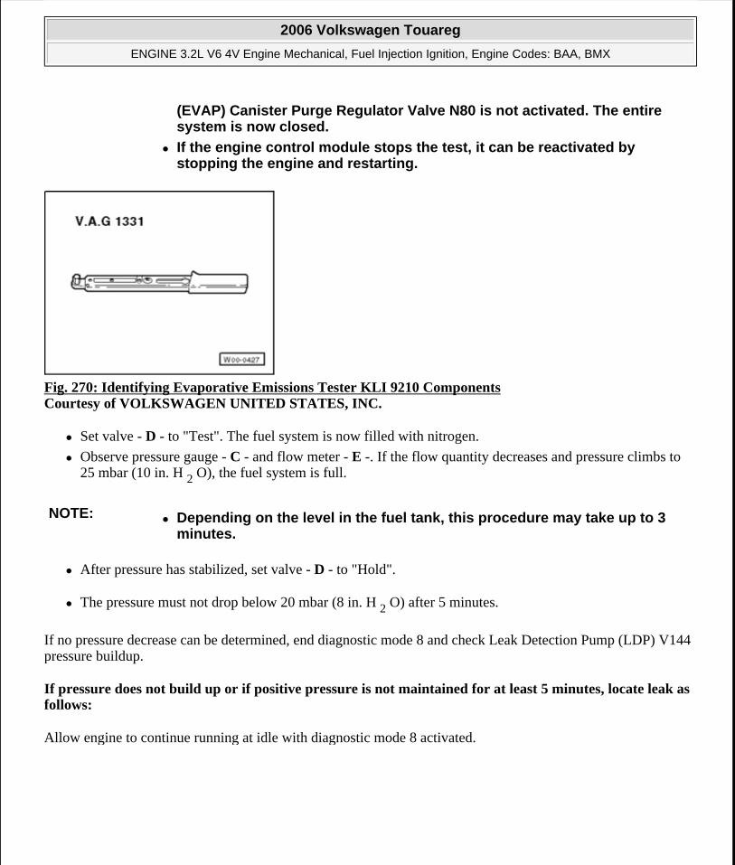
Fig. 270: Identifying Evaporative Emissions Tester KLI 9210 Components Courtesy of VOLKSWAGEN UNITED STATES, INC.
Set valve - D - to "Test". The fuel system is now filled with nitrogen.
Observe pressure gauge - C - and flow meter - E -. If the flow quantity decreases and pressure climbs to 25 mbar (10 in. H 2 O), the fuel system is full.
After pressure has stabilized, set valve - D - to "Hold".
The pressure must not drop below 20 mbar (8 in. H 2 O) after 5 minutes.
If no pressure decrease can be determined, end diagnostic mode 8 and check Leak Detection Pump (LDP) V144 pressure buildup.
If pressure does not build up or if positive pressure is not maintained for at least 5 minutes, locate leak as follows:
Allow engine to continue running at idle with diagnostic mode 8 activated.
(EVAP) Canister Purge Regulator Valve N80 is not activated. The entire system is now closed.
If the engine control module stops the test, it can be reactivated by stopping the engine and restarting.
NOTE: Depending on the level in the fuel tank, this procedure may take up to 3 minutes.
2006 Volkswagen Touareg
ENGINE 3.2L V6 4V Engine Mechanical, Fuel Injection Ignition, Engine Codes: BAA, BMX
Microsoft
Sunday, September 20, 2009 9:14:19 AM Page 228 © 2005 Mitchell Repair Information Company, LLC.
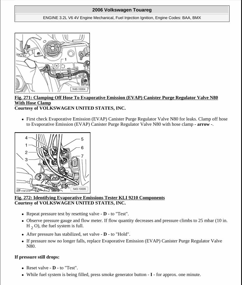
Fig. 271: Clamping Off Hose To Evaporative Emission (EVAP) Canister Purge Regulator Valve N80 With Hose Clamp Courtesy of VOLKSWAGEN UNITED STATES, INC.
First check Evaporative Emission (EVAP) Canister Purge Regulator Valve N80 for leaks. Clamp off hose to Evaporative Emission (EVAP) Canister Purge Regulator Valve N80 with hose clamp - arrow -.
Fig. 272: Identifying Evaporative Emissions Tester KLI 9210 Components Courtesy of VOLKSWAGEN UNITED STATES, INC.
Repeat pressure test by resetting valve - D - to "Test".
Observe pressure gauge and flow meter. If flow quantity decreases and pressure climbs to 25 mbar (10 in. H 2 O), the fuel system is full.
After pressure has stabilized, set valve - D - to "Hold".
If pressure now no longer falls, replace Evaporative Emission (EVAP) Canister Purge Regulator Valve N80.
If pressure still drops:
Reset valve - D - to "Test".
While fuel system is being filled, press smoke generator button - I - for approx. one minute.
2006 Volkswagen Touareg
ENGINE 3.2L V6 4V Engine Mechanical, Fuel Injection Ignition, Engine Codes: BAA, BMX
Microsoft
Sunday, September 20, 2009 9:14:19 AM Page 229 © 2005 Mitchell Repair Information Company, LLC.
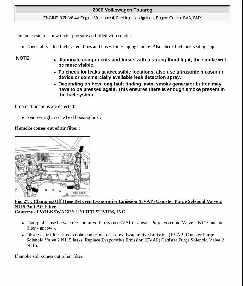
The fuel system is now under pressure and filled with smoke.
Check all visible fuel system lines and hoses for escaping smoke. Also check fuel tank sealing cap.
If no malfunctions are detected:
Remove right rear wheel housing liner.
If smoke comes out of air filter :
Fig. 273: Clamping Off Hose Between Evaporative Emission (EVAP) Canister Purge Solenoid Valve 2 N115 And Air Filter Courtesy of VOLKSWAGEN UNITED STATES, INC.
Clamp off hose between Evaporative Emission (EVAP) Canister Purge Solenoid Valve 2 N115 and air filter - arrow -.
Observe air filter. If no smoke comes out of it now, Evaporative Emission (EVAP) Canister Purge Solenoid Valve 2 N115 leaks. Replace Evaporative Emission (EVAP) Canister Purge Solenoid Valve 2 N115.
If smoke still comes out of air filter:
NOTE: Illuminate components and hoses with a strong flood light, the smoke will be more visible.
To check for leaks at accessible locations, also use ultrasonic measuring device or commercially available leak detection spray.
Depending on how long fault finding lasts, smoke generator button may have to be pressed again. This ensures there is enough smoke present in the fuel system.
2006 Volkswagen Touareg
ENGINE 3.2L V6 4V Engine Mechanical, Fuel Injection Ignition, Engine Codes: BAA, BMX
Microsoft
Sunday, September 20, 2009 9:14:19 AM Page 230 © 2005 Mitchell Repair Information Company, LLC.
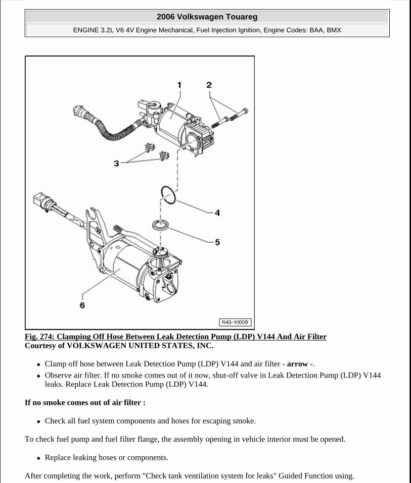
Fig. 274: Clamping Off Hose Between Leak Detection Pump (LDP) V144 And Air Filter Courtesy of VOLKSWAGEN UNITED STATES, INC.
Clamp off hose between Leak Detection Pump (LDP) V144 and air filter - arrow -.
Observe air filter. If no smoke comes out of it now, shut-off valve in Leak Detection Pump (LDP) V144 leaks. Replace Leak Detection Pump (LDP) V144.
If no smoke comes out of air filter :
Check all fuel system components and hoses for escaping smoke.
To check fuel pump and fuel filter flange, the assembly opening in vehicle interior must be opened.
Replace leaking hoses or components.
After completing the work, perform "Check tank ventilation system for leaks" Guided Function using.
2006 Volkswagen Touareg
ENGINE 3.2L V6 4V Engine Mechanical, Fuel Injection Ignition, Engine Codes: BAA, BMX
Microsoft
Sunday, September 20, 2009 9:14:19 AM Page 231 © 2005 Mitchell Repair Information Company, LLC.
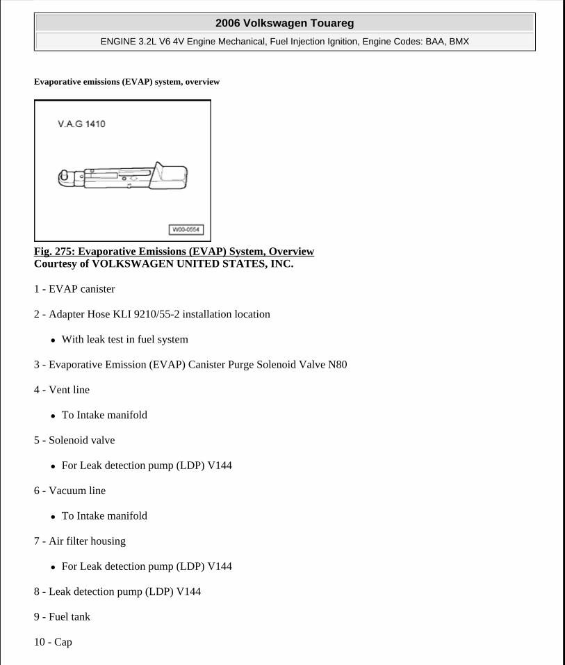
Evaporative emissions (EVAP) system, overview
Fig. 275: Evaporative Emissions (EVAP) System, Overview Courtesy of VOLKSWAGEN UNITED STATES, INC.
1 - EVAP canister
2 - Adapter Hose KLI 9210/55-2 installation location
With leak test in fuel system
3 - Evaporative Emission (EVAP) Canister Purge Solenoid Valve N80
4 - Vent line
To Intake manifold
5 - Solenoid valve
For Leak detection pump (LDP) V144
6 - Vacuum line
To Intake manifold
7 - Air filter housing
For Leak detection pump (LDP) V144
8 - Leak detection pump (LDP) V144
9 - Fuel tank
10 - Cap
2006 Volkswagen Touareg
ENGINE 3.2L V6 4V Engine Mechanical, Fuel Injection Ignition, Engine Codes: BAA, BMX
Microsoft
Sunday, September 20, 2009 9:14:19 AM Page 232 © 2005 Mitchell Repair Information Company, LLC.
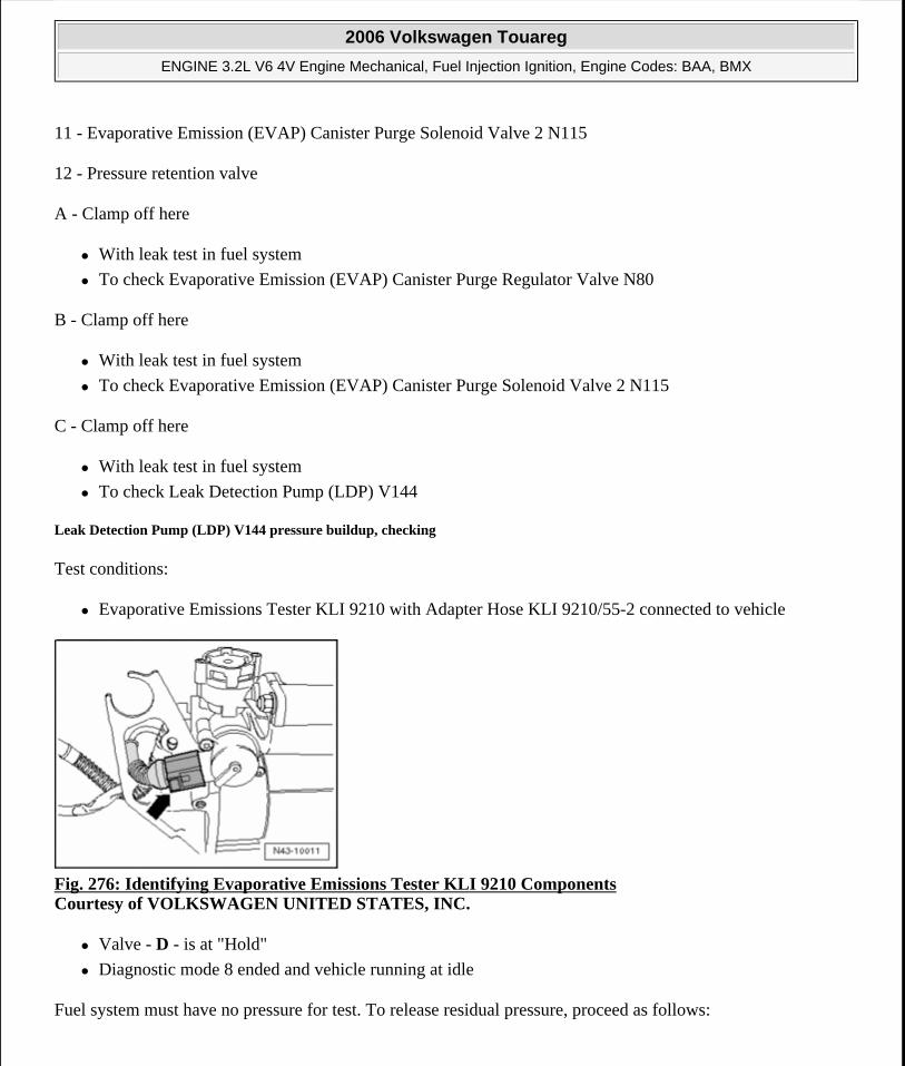
11 - Evaporative Emission (EVAP) Canister Purge Solenoid Valve 2 N115
12 - Pressure retention valve
A - Clamp off here
With leak test in fuel system
To check Evaporative Emission (EVAP) Canister Purge Regulator Valve N80
B - Clamp off here
With leak test in fuel system
To check Evaporative Emission (EVAP) Canister Purge Solenoid Valve 2 N115
C - Clamp off here
With leak test in fuel system
To check Leak Detection Pump (LDP) V144
Leak Detection Pump (LDP) V144 pressure buildup, checking
Test conditions:
Evaporative Emissions Tester KLI 9210 with Adapter Hose KLI 9210/55-2 connected to vehicle
Fig. 276: Identifying Evaporative Emissions Tester KLI 9210 Components Courtesy of VOLKSWAGEN UNITED STATES, INC.
Valve - D - is at "Hold"
Diagnostic mode 8 ended and vehicle running at idle
Fuel system must have no pressure for test. To release residual pressure, proceed as follows:
2006 Volkswagen Touareg
ENGINE 3.2L V6 4V Engine Mechanical, Fuel Injection Ignition, Engine Codes: BAA, BMX
Microsoft
Sunday, September 20, 2009 9:14:19 AM Page 233 © 2005 Mitchell Repair Information Company, LLC.
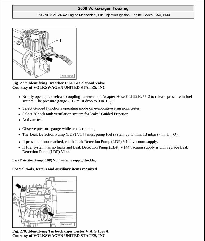
Fig. 277: Identifying Breather Line To Solenoid Valve Courtesy of VOLKSWAGEN UNITED STATES, INC.
Briefly open quick-release coupling - arrow - on Adapter Hose KLI 9210/55-2 to release pressure in fuel system. The pressure gauge - D - must drop to 0 in. H 2 O.
Select Guided Functions operating mode on evaporative emissions tester.
Select "Check tank ventilation system for leaks" Guided Function.
Activate test.
Observe pressure gauge while test is running.
The Leak Detection Pump (LDP) V144 must pump fuel system up to min. 18 mbar (7 in. H 2 O).
If pressure is not reached, check Leak Detection Pump (LDP) V144 vacuum supply.
If fuel system has no leaks and Leak Detection Pump (LDP) V144 vacuum supply is OK, replace Leak Detection Pump (LDP) V144.
Leak Detection Pump (LDP) V144 vacuum supply, checking
Special tools, testers and auxiliary items required
Fig. 278: Identifying Turbocharger Tester V.A.G 1397A Courtesy of VOLKSWAGEN UNITED STATES, INC.
2006 Volkswagen Touareg
ENGINE 3.2L V6 4V Engine Mechanical, Fuel Injection Ignition, Engine Codes: BAA, BMX
Microsoft
Sunday, September 20, 2009 9:14:19 AM Page 234 © 2005 Mitchell Repair Information Company, LLC.
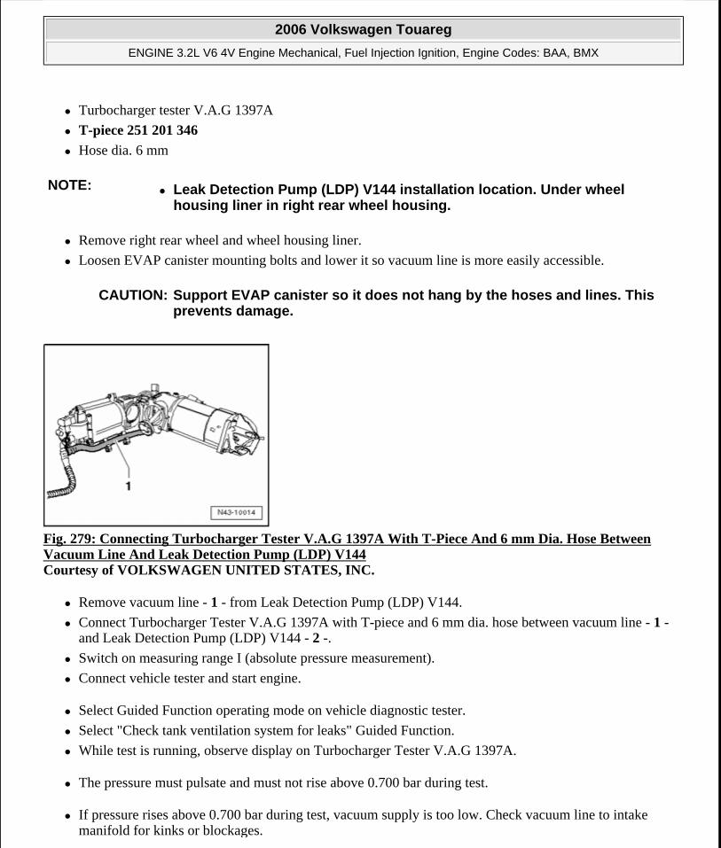
Turbocharger tester V.A.G 1397A
T-piece 251 201 346
Hose dia. 6 mm
Remove right rear wheel and wheel housing liner.
Loosen EVAP canister mounting bolts and lower it so vacuum line is more easily accessible.
Fig. 279: Connecting Turbocharger Tester V.A.G 1397A With T-Piece And 6 mm Dia. Hose Between Vacuum Line And Leak Detection Pump (LDP) V144 Courtesy of VOLKSWAGEN UNITED STATES, INC.
Remove vacuum line - 1 - from Leak Detection Pump (LDP) V144.
Connect Turbocharger Tester V.A.G 1397A with T-piece and 6 mm dia. hose between vacuum line - 1 - and Leak Detection Pump (LDP) V144 - 2 -.
Switch on measuring range I (absolute pressure measurement).
Connect vehicle tester and start engine.
Select Guided Function operating mode on vehicle diagnostic tester.
Select "Check tank ventilation system for leaks" Guided Function.
While test is running, observe display on Turbocharger Tester V.A.G 1397A.
The pressure must pulsate and must not rise above 0.700 bar during test.
If pressure rises above 0.700 bar during test, vacuum supply is too low. Check vacuum line to intake manifold for kinks or blockages.
NOTE: Leak Detection Pump (LDP) V144 installation location. Under wheel housing liner in right rear wheel housing.
CAUTION: Support EVAP canister so it does not hang by the hoses and lines. This prevents damage.
2006 Volkswagen Touareg
ENGINE 3.2L V6 4V Engine Mechanical, Fuel Injection Ignition, Engine Codes: BAA, BMX
Microsoft
Sunday, September 20, 2009 9:14:19 AM Page 235 © 2005 Mitchell Repair Information Company, LLC.
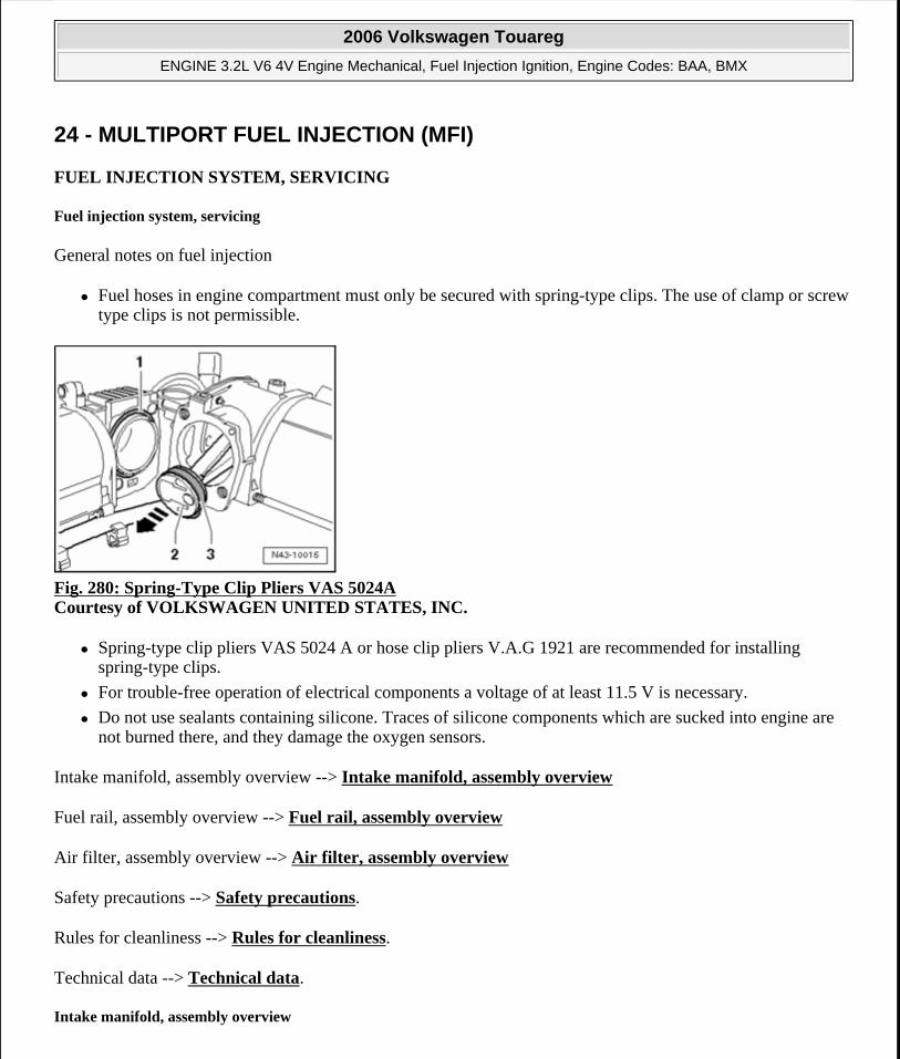
24 - MULTIPORT FUEL INJECTION (MFI)
FUEL INJECTION SYSTEM, SERVICING
Fuel injection system, servicing
General notes on fuel injection
Fuel hoses in engine compartment must only be secured with spring-type clips. The use of clamp or screw type clips is not permissible.
Fig. 280: Spring-Type Clip Pliers VAS 5024A Courtesy of VOLKSWAGEN UNITED STATES, INC.
Spring-type clip pliers VAS 5024 A or hose clip pliers V.A.G 1921 are recommended for installing spring-type clips.
For trouble-free operation of electrical components a voltage of at least 11.5 V is necessary.
Do not use sealants containing silicone. Traces of silicone components which are sucked into engine are not burned there, and they damage the oxygen sensors.
Intake manifold, assembly overview --> Intake manifold, assembly overview
Fuel rail, assembly overview --> Fuel rail, assembly overview
Air filter, assembly overview --> Air filter, assembly overview
Safety precautions --> Safety precautions.
Rules for cleanliness --> Rules for cleanliness.
Technical data --> Technical data.
Intake manifold, assembly overview
2006 Volkswagen Touareg
ENGINE 3.2L V6 4V Engine Mechanical, Fuel Injection Ignition, Engine Codes: BAA, BMX
Microsoft
Sunday, September 20, 2009 9:14:19 AM Page 236 © 2005 Mitchell Repair Information Company, LLC.
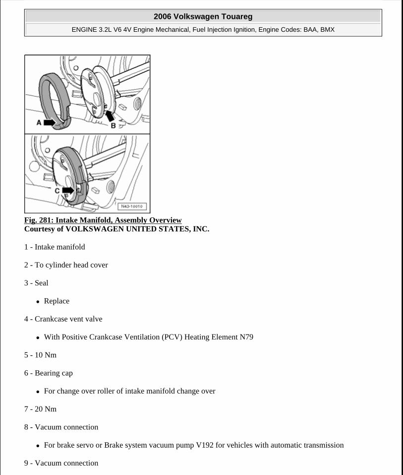
Fig. 281: Intake Manifold, Assembly Overview Courtesy of VOLKSWAGEN UNITED STATES, INC.
1 - Intake manifold
2 - To cylinder head cover
3 - Seal
Replace
4 - Crankcase vent valve
With Positive Crankcase Ventilation (PCV) Heating Element N79
5 - 10 Nm
6 - Bearing cap
For change over roller of intake manifold change over
7 - 20 Nm
8 - Vacuum connection
For brake servo or Brake system vacuum pump V192 for vehicles with automatic transmission
9 - Vacuum connection
2006 Volkswagen Touareg
ENGINE 3.2L V6 4V Engine Mechanical, Fuel Injection Ignition, Engine Codes: BAA, BMX
Microsoft
Sunday, September 20, 2009 9:14:19 AM Page 237 © 2005 Mitchell Repair Information Company, LLC.
For leak detection pump V144 on vehicles with engine code BAA and BMX
Closed with plugs on vehicles with engine code AZZ, BKJ, BMV and BRJ
10 - Vacuum connection
For Secondary Air Injection (AIR) solenoid valve N112 and Intake Manifold Tuning (IMT) Valve N156
11 - Vacuum connection
For evaporative emission (EVAP) canister purge regulator valve N80
12 - 20 Nm
13 - Throttle valve control module J338
Terminals of harness connector are gold-plated
Adapt to throttle valve control module when replacing Engine Control Module (ECM) "Guided Functions".
14 - 10 Nm
15 - Vacuum actuator
For variable intake manifold
16 - To Intake Manifold Tuning (IMT) Valve N156
17 - 10 Nm
18 - Control lever
For change over roller
Ensure seated tightly
19 - Change over roller
20 - Gasket
Note installation position
Replace if damaged
21 - Dowel sleeve
For intake manifold mount
For attaching seal
2006 Volkswagen Touareg
ENGINE 3.2L V6 4V Engine Mechanical, Fuel Injection Ignition, Engine Codes: BAA, BMX
Microsoft
Sunday, September 20, 2009 9:14:19 AM Page 238 © 2005 Mitchell Repair Information Company, LLC.
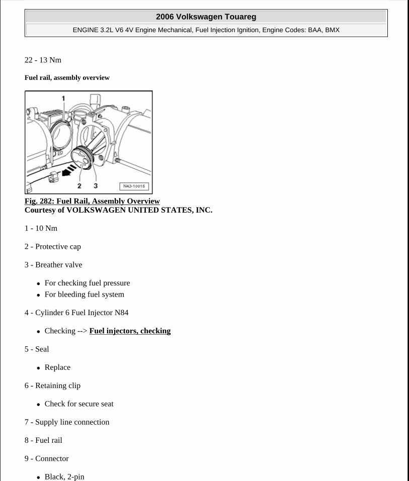
22 - 13 Nm
Fuel rail, assembly overview
Fig. 282: Fuel Rail, Assembly Overview Courtesy of VOLKSWAGEN UNITED STATES, INC.
1 - 10 Nm
2 - Protective cap
3 - Breather valve
For checking fuel pressure
For bleeding fuel system
4 - Cylinder 6 Fuel Injector N84
Checking --> Fuel injectors, checking
5 - Seal
Replace
6 - Retaining clip
Check for secure seat
7 - Supply line connection
8 - Fuel rail
9 - Connector
Black, 2-pin
2006 Volkswagen Touareg
ENGINE 3.2L V6 4V Engine Mechanical, Fuel Injection Ignition, Engine Codes: BAA, BMX
Microsoft
Sunday, September 20, 2009 9:14:20 AM Page 239 © 2005 Mitchell Repair Information Company, LLC.
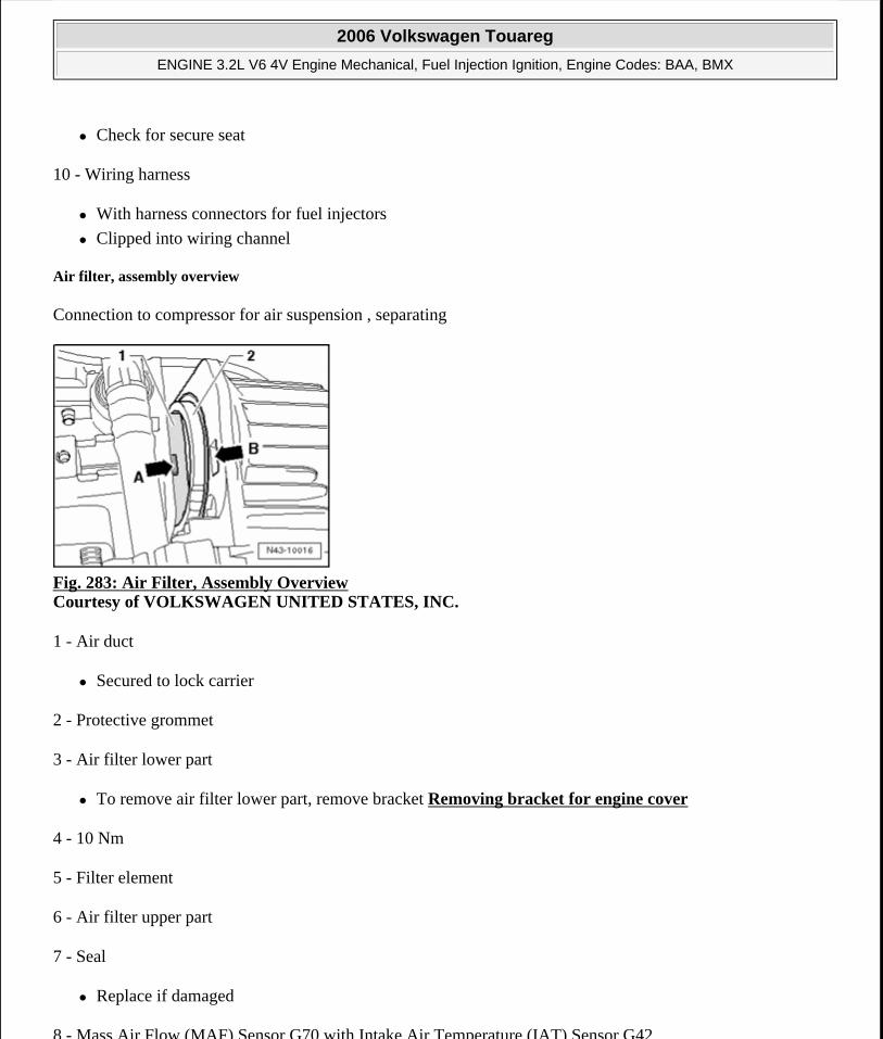
Check for secure seat
10 - Wiring harness
With harness connectors for fuel injectors
Clipped into wiring channel
Air filter, assembly overview
Connection to compressor for air suspension , separating
Fig. 283: Air Filter, Assembly Overview Courtesy of VOLKSWAGEN UNITED STATES, INC.
1 - Air duct
Secured to lock carrier
2 - Protective grommet
3 - Air filter lower part
To remove air filter lower part, remove bracket Removing bracket for engine cover
4 - 10 Nm
5 - Filter element
6 - Air filter upper part
7 - Seal
Replace if damaged
8 - Mass Air Flow (MAF) Sensor G70 with Intake Air Temperature (IAT) Sensor G42
2006 Volkswagen Touareg
ENGINE 3.2L V6 4V Engine Mechanical, Fuel Injection Ignition, Engine Codes: BAA, BMX
Microsoft
Sunday, September 20, 2009 9:14:20 AM Page 240 © 2005 Mitchell Repair Information Company, LLC.
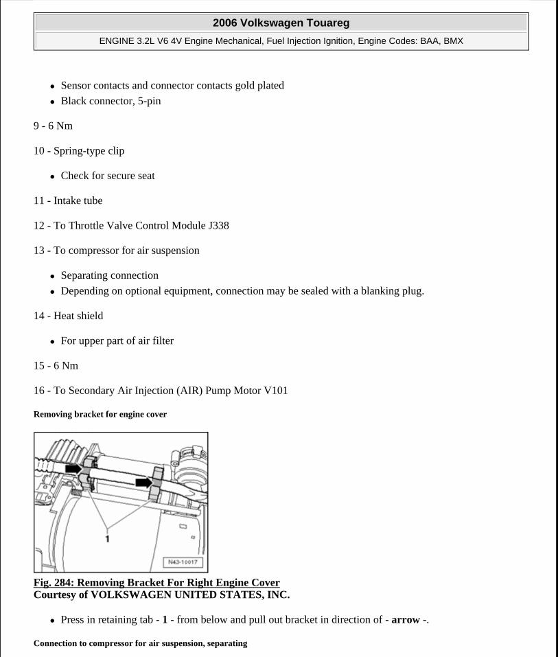
Sensor contacts and connector contacts gold plated
Black connector, 5-pin
9 - 6 Nm
10 - Spring-type clip
Check for secure seat
11 - Intake tube
12 - To Throttle Valve Control Module J338
13 - To compressor for air suspension
Separating connection
Depending on optional equipment, connection may be sealed with a blanking plug.
14 - Heat shield
For upper part of air filter
15 - 6 Nm
16 - To Secondary Air Injection (AIR) Pump Motor V101
Removing bracket for engine cover
Fig. 284: Removing Bracket For Right Engine Cover Courtesy of VOLKSWAGEN UNITED STATES, INC.
Press in retaining tab - 1 - from below and pull out bracket in direction of - arrow -.
Connection to compressor for air suspension, separating
2006 Volkswagen Touareg
ENGINE 3.2L V6 4V Engine Mechanical, Fuel Injection Ignition, Engine Codes: BAA, BMX
Microsoft
Sunday, September 20, 2009 9:14:20 AM Page 241 © 2005 Mitchell Repair Information Company, LLC.
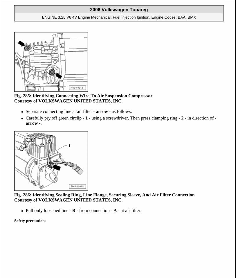
Fig. 285: Identifying Connecting Wire To Air Suspension Compressor Courtesy of VOLKSWAGEN UNITED STATES, INC.
Separate connecting line at air filter - arrow - as follows:
Carefully pry off green circlip - 1 - using a screwdriver. Then press clamping ring - 2 - in direction of - arrow -.
Fig. 286: Identifying Sealing Ring, Line Flange, Securing Sleeve, And Air Filter Connection Courtesy of VOLKSWAGEN UNITED STATES, INC.
Pull only loosened line - B - from connection - A - at air filter.
Safety precautions
2006 Volkswagen Touareg
ENGINE 3.2L V6 4V Engine Mechanical, Fuel Injection Ignition, Engine Codes: BAA, BMX
Microsoft
Sunday, September 20, 2009 9:14:20 AM Page 242 © 2005 Mitchell Repair Information Company, LLC.
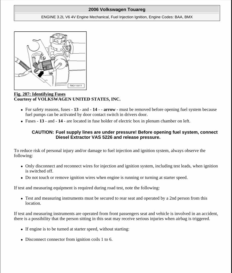
Fig. 287: Identifying Fuses Courtesy of VOLKSWAGEN UNITED STATES, INC.
For safety reasons, fuses - 13 - and - 14 - - arrow - must be removed before opening fuel system because fuel pumps can be activated by door contact switch in drivers door.
Fuses - 13 - and - 14 - are located in fuse holder of electric box in plenum chamber on left.
To reduce risk of personal injury and/or damage to fuel injection and ignition system, always observe the following:
Only disconnect and reconnect wires for injection and ignition system, including test leads, when ignition is switched off.
Do not touch or remove ignition wires when engine is running or turning at starter speed.
If test and measuring equipment is required during road test, note the following:
Test and measuring instruments must be secured to rear seat and operated by a 2nd person from this location.
If test and measuring instruments are operated from front passengers seat and vehicle is involved in an accident, there is a possibility that the person sitting in this seat may receive serious injuries when airbag is triggered.
If engine is to be turned at starter speed, without starting:
Disconnect connector from ignition coils 1 to 6.
CAUTION: Fuel supply lines are under pressure! Before opening fuel system, connect Diesel Extractor VAS 5226 and release pressure.
2006 Volkswagen Touareg
ENGINE 3.2L V6 4V Engine Mechanical, Fuel Injection Ignition, Engine Codes: BAA, BMX
Microsoft
Sunday, September 20, 2009 9:14:20 AM Page 243 © 2005 Mitchell Repair Information Company, LLC.
Fig. 288: Identifying Assembly Tool T10118 On Release Button Courtesy of VOLKSWAGEN UNITED STATES, INC.
To do so, place assembly tool T10118 on locking button - arrow - and carefully pull down harness connector.
Rules for cleanliness
When working on fuel supply/injection system, pay careful attention to the following "5 rules" of cleanliness:
Thoroughly clean all connections and surrounding area before disconnecting.
Place parts that have been removed on a clean surface and cover them. Use lint-free cloths.
Carefully cover over opened components or seal, if repairs are not performed immediately.
Only install clean components: Only unpack replacement parts immediately prior to installation. Do not use parts that have been stored loose (e.g. in tool boxes etc.).
When system is open: Avoid working with compressed air if possible. Do not move vehicle unless absolutely necessary.
Technical data
*Not adjustable
COMPONENTS, CHECKING
Fuel injectors, checking
Engine code BAA BMXIdle check Engine idle speed * See note RPM 650 to 750 650 to 750Engine control module System designation Motronic ME7.1.1 Motronic ME7.1.1 Replacement part number Engine speed (RPM) limitation RPM from approx. 6500 from approx. 6500
2006 Volkswagen Touareg
ENGINE 3.2L V6 4V Engine Mechanical, Fuel Injection Ignition, Engine Codes: BAA, BMX
Microsoft
Sunday, September 20, 2009 9:14:20 AM Page 244 © 2005 Mitchell Repair Information Company, LLC.
Checking for leaks
Checking injection quantity
Special tools, testers and auxiliary items required
Remote control connection V.A.G 1348/3A
Adapter cable V.A.G 1348/3-2
Adapter cable, 121-pin V.A.G 1598/31
Injector quantity testing device V.A.G 1602
Not illustrated:
Adapter cable V.A.G 1348/3-3
Connector test set V.A.G 1594C
Test conditions
Fuel pressure must be OK, check --> Fuel pressure regulator and residual pressure, checking , fuel pressure regulator and retaining pressure, checking.
Test sequence
Remove intake manifold --> Cylinder head cover, removing and installing , Cylinder head cover, removing and installing
Remove complete fuel rail (fuel lines remain attached) --> Fuel rail, assembly overview , Fuel rail, disassembling and assembling.
Checking for leaks
Remove cover over fuse holder.
Fig. 289: Identifying Fuel Pump Relays Courtesy of VOLKSWAGEN UNITED STATES, INC.
2006 Volkswagen Touareg
ENGINE 3.2L V6 4V Engine Mechanical, Fuel Injection Ignition, Engine Codes: BAA, BMX
Microsoft
Sunday, September 20, 2009 9:14:20 AM Page 245 © 2005 Mitchell Repair Information Company, LLC.
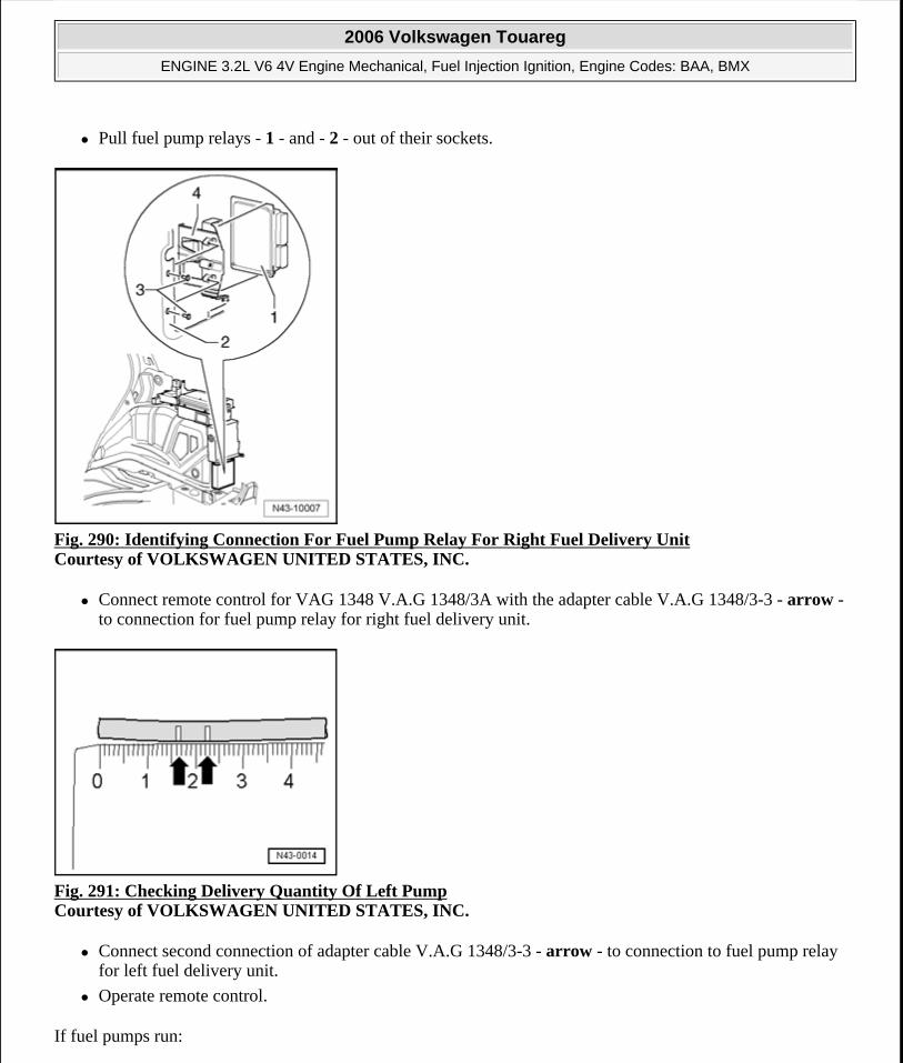
Pull fuel pump relays - 1 - and - 2 - out of their sockets.
Fig. 290: Identifying Connection For Fuel Pump Relay For Right Fuel Delivery Unit Courtesy of VOLKSWAGEN UNITED STATES, INC.
Connect remote control for VAG 1348 V.A.G 1348/3A with the adapter cable V.A.G 1348/3-3 - arrow - to connection for fuel pump relay for right fuel delivery unit.
Fig. 291: Checking Delivery Quantity Of Left Pump Courtesy of VOLKSWAGEN UNITED STATES, INC.
Connect second connection of adapter cable V.A.G 1348/3-3 - arrow - to connection to fuel pump relay for left fuel delivery unit.
Operate remote control.
If fuel pumps run:
2006 Volkswagen Touareg
ENGINE 3.2L V6 4V Engine Mechanical, Fuel Injection Ignition, Engine Codes: BAA, BMX
Microsoft
Sunday, September 20, 2009 9:14:20 AM Page 246 © 2005 Mitchell Repair Information Company, LLC.
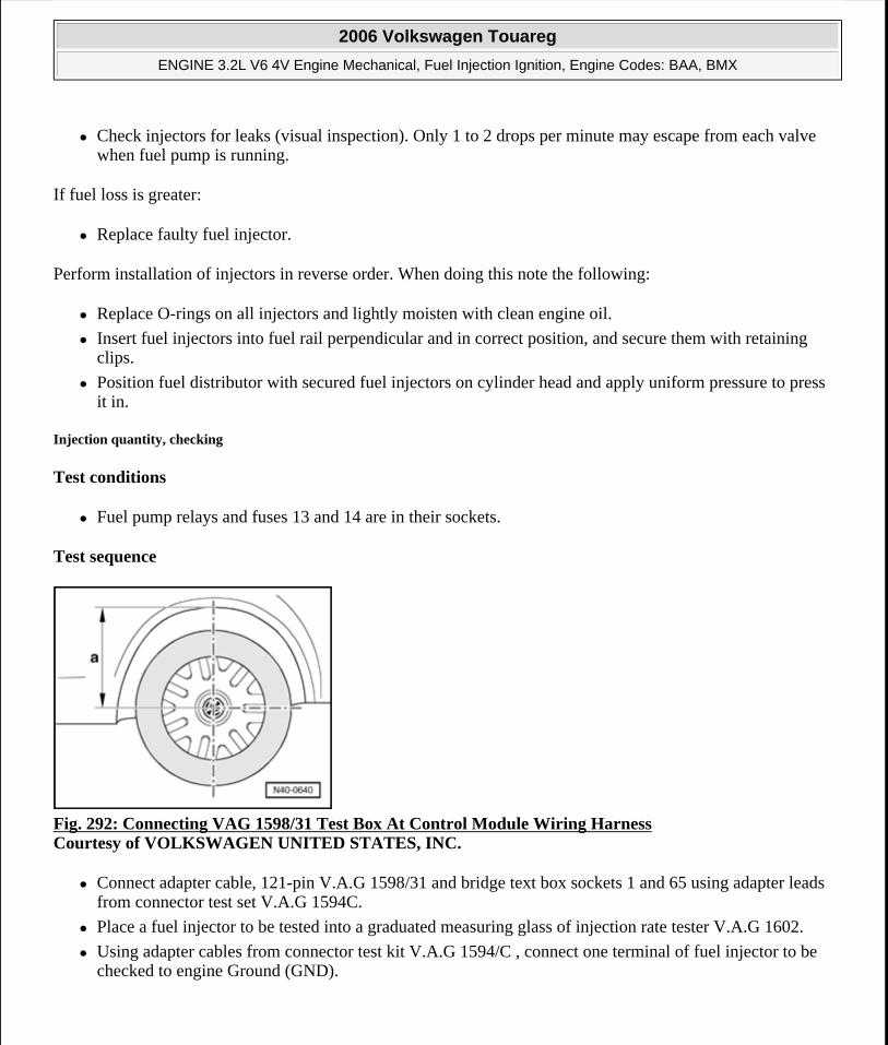
Check injectors for leaks (visual inspection). Only 1 to 2 drops per minute may escape from each valve when fuel pump is running.
If fuel loss is greater:
Replace faulty fuel injector.
Perform installation of injectors in reverse order. When doing this note the following:
Replace O-rings on all injectors and lightly moisten with clean engine oil.
Insert fuel injectors into fuel rail perpendicular and in correct position, and secure them with retaining clips.
Position fuel distributor with secured fuel injectors on cylinder head and apply uniform pressure to press it in.
Injection quantity, checking
Test conditions
Fuel pump relays and fuses 13 and 14 are in their sockets.
Test sequence
Fig. 292: Connecting VAG 1598/31 Test Box At Control Module Wiring Harness Courtesy of VOLKSWAGEN UNITED STATES, INC.
Connect adapter cable, 121-pin V.A.G 1598/31 and bridge text box sockets 1 and 65 using adapter leads from connector test set V.A.G 1594C.
Place a fuel injector to be tested into a graduated measuring glass of injection rate tester V.A.G 1602.
Using adapter cables from connector test kit V.A.G 1594/C , connect one terminal of fuel injector to be checked to engine Ground (GND).
2006 Volkswagen Touareg
ENGINE 3.2L V6 4V Engine Mechanical, Fuel Injection Ignition, Engine Codes: BAA, BMX
Microsoft
Sunday, September 20, 2009 9:14:20 AM Page 247 © 2005 Mitchell Repair Information Company, LLC.
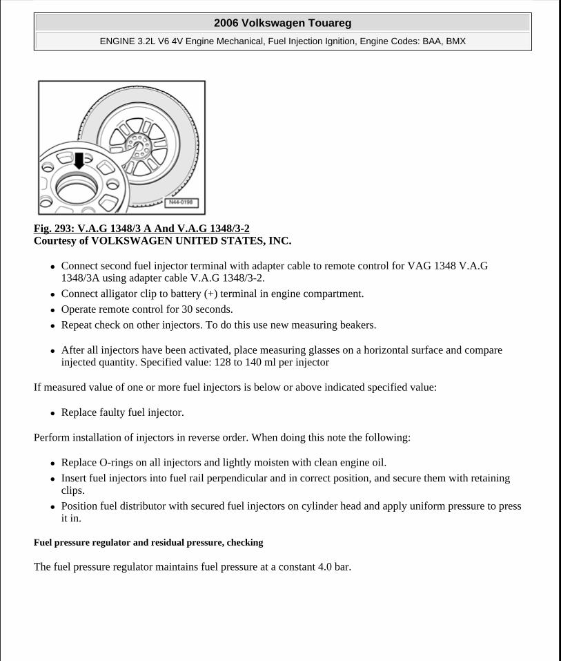
Fig. 293: V.A.G 1348/3 A And V.A.G 1348/3-2 Courtesy of VOLKSWAGEN UNITED STATES, INC.
Connect second fuel injector terminal with adapter cable to remote control for VAG 1348 V.A.G 1348/3A using adapter cable V.A.G 1348/3-2.
Connect alligator clip to battery (+) terminal in engine compartment.
Operate remote control for 30 seconds.
Repeat check on other injectors. To do this use new measuring beakers.
After all injectors have been activated, place measuring glasses on a horizontal surface and compare injected quantity. Specified value: 128 to 140 ml per injector
If measured value of one or more fuel injectors is below or above indicated specified value:
Replace faulty fuel injector.
Perform installation of injectors in reverse order. When doing this note the following:
Replace O-rings on all injectors and lightly moisten with clean engine oil.
Insert fuel injectors into fuel rail perpendicular and in correct position, and secure them with retaining clips.
Position fuel distributor with secured fuel injectors on cylinder head and apply uniform pressure to press it in.
Fuel pressure regulator and residual pressure, checking
The fuel pressure regulator maintains fuel pressure at a constant 4.0 bar.
2006 Volkswagen Touareg
ENGINE 3.2L V6 4V Engine Mechanical, Fuel Injection Ignition, Engine Codes: BAA, BMX
Microsoft
Sunday, September 20, 2009 9:14:20 AM Page 248 © 2005 Mitchell Repair Information Company, LLC.
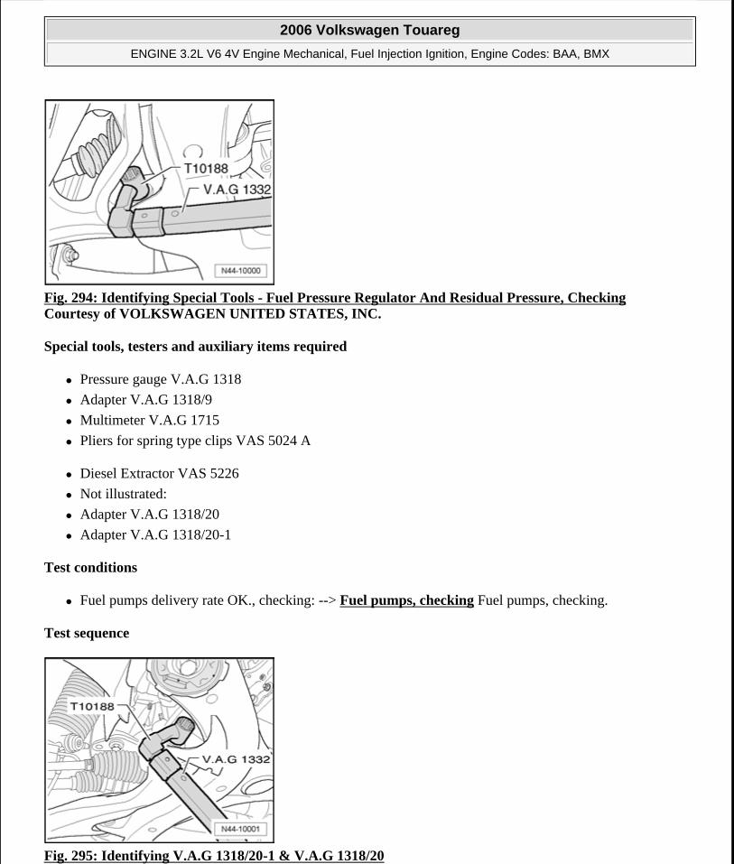
Fig. 294: Identifying Special Tools - Fuel Pressure Regulator And Residual Pressure, Checking Courtesy of VOLKSWAGEN UNITED STATES, INC.
Special tools, testers and auxiliary items required
Pressure gauge V.A.G 1318
Adapter V.A.G 1318/9
Multimeter V.A.G 1715
Pliers for spring type clips VAS 5024 A
Diesel Extractor VAS 5226
Not illustrated:
Adapter V.A.G 1318/20
Adapter V.A.G 1318/20-1
Test conditions
Fuel pumps delivery rate OK., checking: --> Fuel pumps, checking Fuel pumps, checking.
Test sequence
Fig. 295: Identifying V.A.G 1318/20-1 & V.A.G 1318/20
2006 Volkswagen Touareg
ENGINE 3.2L V6 4V Engine Mechanical, Fuel Injection Ignition, Engine Codes: BAA, BMX
Microsoft
Sunday, September 20, 2009 9:14:20 AM Page 249 © 2005 Mitchell Repair Information Company, LLC.
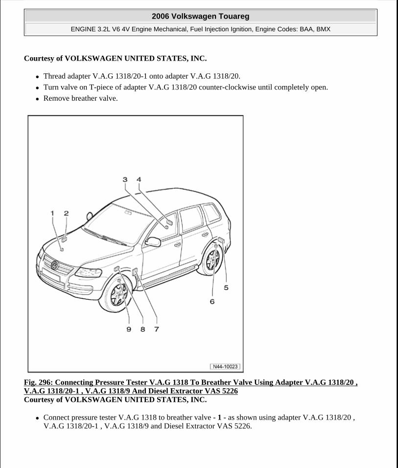
Courtesy of VOLKSWAGEN UNITED STATES, INC.
Thread adapter V.A.G 1318/20-1 onto adapter V.A.G 1318/20.
Turn valve on T-piece of adapter V.A.G 1318/20 counter-clockwise until completely open.
Remove breather valve.
Fig. 296: Connecting Pressure Tester V.A.G 1318 To Breather Valve Using Adapter V.A.G 1318/20 , V.A.G 1318/20-1 , V.A.G 1318/9 And Diesel Extractor VAS 5226 Courtesy of VOLKSWAGEN UNITED STATES, INC.
Connect pressure tester V.A.G 1318 to breather valve - 1 - as shown using adapter V.A.G 1318/20 , V.A.G 1318/20-1 , V.A.G 1318/9 and Diesel Extractor VAS 5226.
2006 Volkswagen Touareg
ENGINE 3.2L V6 4V Engine Mechanical, Fuel Injection Ignition, Engine Codes: BAA, BMX
Microsoft
Sunday, September 20, 2009 9:14:20 AM Page 250 © 2005 Mitchell Repair Information Company, LLC.
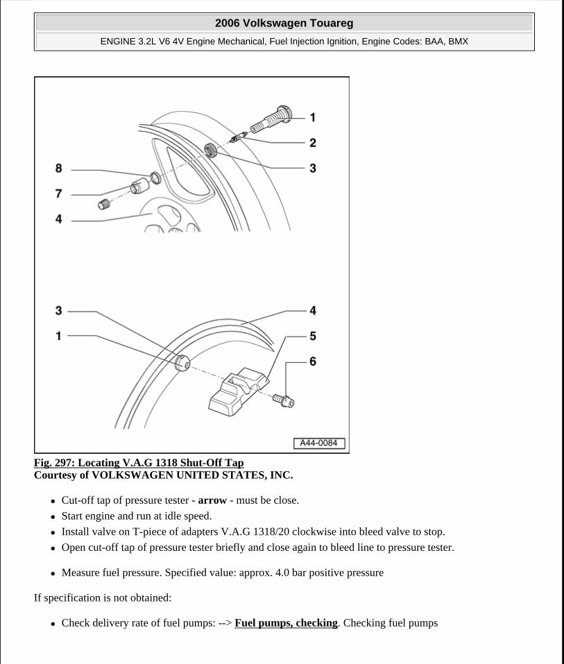
Fig. 297: Locating V.A.G 1318 Shut-Off Tap Courtesy of VOLKSWAGEN UNITED STATES, INC.
Cut-off tap of pressure tester - arrow - must be close.
Start engine and run at idle speed.
Install valve on T-piece of adapters V.A.G 1318/20 clockwise into bleed valve to stop.
Open cut-off tap of pressure tester briefly and close again to bleed line to pressure tester.
Measure fuel pressure. Specified value: approx. 4.0 bar positive pressure
If specification is not obtained:
Check delivery rate of fuel pumps: --> Fuel pumps, checking. Checking fuel pumps
2006 Volkswagen Touareg
ENGINE 3.2L V6 4V Engine Mechanical, Fuel Injection Ignition, Engine Codes: BAA, BMX
Microsoft
Sunday, September 20, 2009 9:14:20 AM Page 251 © 2005 Mitchell Repair Information Company, LLC.
Fig. 298: Individual Components Of Flange, Right Side Courtesy of VOLKSWAGEN UNITED STATES, INC.
If necessary, replace fuel pressure regulator - 2 -.
If specified value is achieved:
Switch off ignition.
Check for leaks and residual pressure. Observe pressure drop on pressure gauge. After 10 minutes there must be a residual pressure of at least 3.0 bar.
The holding pressure drops below 3 bar:
Check pressure gauge for leaks.
Check fuel pump non-return valve --> Fuel pumps, checking.
When removing pressure gauge after completing test:
Switch off ignition.
Open cut-off valve of pressure tester to release fuel pressure.
Remove pressure gauge with adapters.
In addition, wrap a cloth around connection to catch fuel which runs out.
ENGINE CONTROL MODULE
Engine Control Module
Removing and installing Engine Control Module (ECM) --> Engine Control Module (ECM), removing and installing
Engine Control Module (ECM) secured with anti-theft immobilizer, removing and installing --> Engine Control Module (ECM) (secured with anti-theft immobilizer), removing and installing
Engine Control Module (ECM), removing and installing
2006 Volkswagen Touareg
ENGINE 3.2L V6 4V Engine Mechanical, Fuel Injection Ignition, Engine Codes: BAA, BMX
Microsoft
Sunday, September 20, 2009 9:14:20 AM Page 252 © 2005 Mitchell Repair Information Company, LLC.
If Engine Control Module (ECM) will be replaced, connect Vehicle Diagnosis, testing info. system VAS 5051B and perform Guided Function "Replace control module".
Removing
Switch off ignition.
Remove windshield wiper motor on right side: --> 92 - WINDSHIELD WIPER AND WASHER SYSTEM
Release both connectors from control module and disconnect them.
Control module can now be removed.
Installing
Set control module into mounting frame.
Connect harness connectors and engage them.
Install windshield wiper motor on right side: --> 92 - WINDSHIELD WIPER AND WASHER SYSTEM
Install plenum chamber cover.
Adapt new Engine Control Module (ECM): "Guided Functions"
Engine Control Module (ECM) (secured with anti-theft immobilizer), removing and installing
Special tools, testers and auxiliary items required
Fig. 299: Wiring Harness Repair Kit V.A.S 1978 Courtesy of VOLKSWAGEN UNITED STATES, INC.
Hot air gun from wiring harness repair kit VAS 1978
NOTE: If it is desired to replace Engine Control Module (ECM), connect Vehicle Diagnosis, Testing and Information System VAS 5051B and perform Guided Function "Replace Engine Control Module (ECM)".
2006 Volkswagen Touareg
ENGINE 3.2L V6 4V Engine Mechanical, Fuel Injection Ignition, Engine Codes: BAA, BMX
Microsoft
Sunday, September 20, 2009 9:14:20 AM Page 253 © 2005 Mitchell Repair Information Company, LLC.
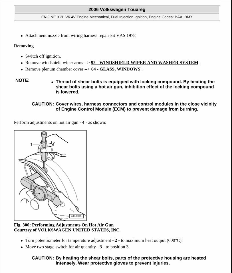
Attachment nozzle from wiring harness repair kit VAS 1978
Removing
Switch off ignition.
Remove windshield wiper arms --> 92 - WINDSHIELD WIPER AND WASHER SYSTEM .
Remove plenum chamber cover --> 64 - GLASS, WINDOWS .
Perform adjustments on hot air gun - 4 - as shown:
Fig. 300: Performing Adjustments On Hot Air Gun Courtesy of VOLKSWAGEN UNITED STATES, INC.
Turn potentiometer for temperature adjustment - 2 - to maximum heat output (600°C).
Move two stage switch for air quantity - 3 - to position 3.
NOTE: Thread of shear bolts is equipped with locking compound. By heating the shear bolts using a hot air gun, inhibition effect of the locking compound is lowered.
CAUTION: Cover wires, harness connectors and control modules in the close vicinity of Engine Control Module (ECM) to prevent damage from burning.
CAUTION: By heating the shear bolts, parts of the protective housing are heated intensely. Wear protective gloves to prevent injuries.
2006 Volkswagen Touareg
ENGINE 3.2L V6 4V Engine Mechanical, Fuel Injection Ignition, Engine Codes: BAA, BMX
Microsoft
Sunday, September 20, 2009 9:14:20 AM Page 254 © 2005 Mitchell Repair Information Company, LLC.
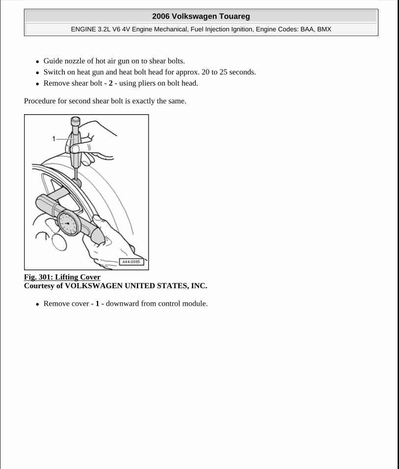
Guide nozzle of hot air gun on to shear bolts.
Switch on heat gun and heat bolt head for approx. 20 to 25 seconds.
Remove shear bolt - 2 - using pliers on bolt head.
Procedure for second shear bolt is exactly the same.
Fig. 301: Lifting Cover Courtesy of VOLKSWAGEN UNITED STATES, INC.
Remove cover - 1 - downward from control module.
2006 Volkswagen Touareg
ENGINE 3.2L V6 4V Engine Mechanical, Fuel Injection Ignition, Engine Codes: BAA, BMX
Microsoft
Sunday, September 20, 2009 9:14:20 AM Page 255 © 2005 Mitchell Repair Information Company, LLC.
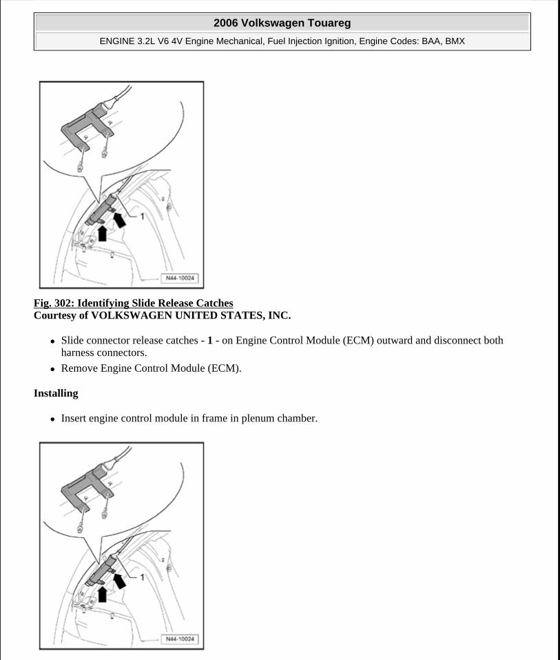
Fig. 302: Identifying Slide Release Catches Courtesy of VOLKSWAGEN UNITED STATES, INC.
Slide connector release catches - 1 - on Engine Control Module (ECM) outward and disconnect both harness connectors.
Remove Engine Control Module (ECM).
Installing
Insert engine control module in frame in plenum chamber.
2006 Volkswagen Touareg
ENGINE 3.2L V6 4V Engine Mechanical, Fuel Injection Ignition, Engine Codes: BAA, BMX
Microsoft
Sunday, September 20, 2009 9:14:20 AM Page 256 © 2005 Mitchell Repair Information Company, LLC.
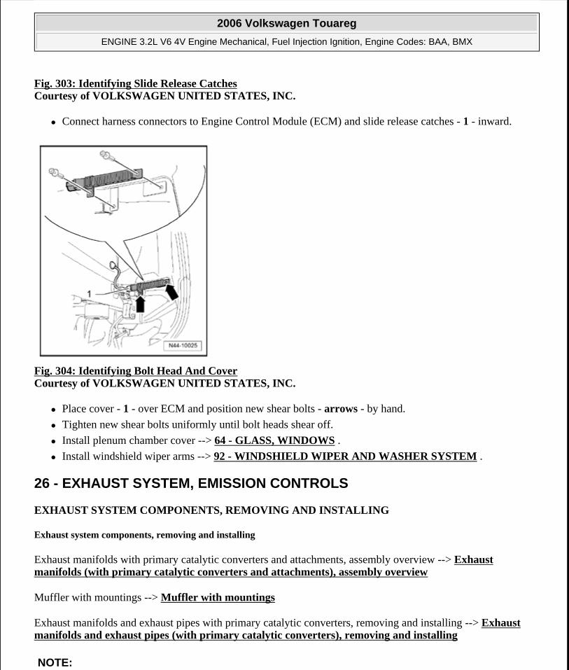
Fig. 303: Identifying Slide Release CatchesCourtesy of VOLKSWAGEN UNITED STATES, INC.
Connect harness connectors to Engine Control Module (ECM) and slide release catches - 1 - inward.
Fig. 304: Identifying Bolt Head And Cover Courtesy of VOLKSWAGEN UNITED STATES, INC.
Place cover - 1 - over ECM and position new shear bolts - arrows - by hand.
Tighten new shear bolts uniformly until bolt heads shear off.
Install plenum chamber cover --> 64 - GLASS, WINDOWS .
Install windshield wiper arms --> 92 - WINDSHIELD WIPER AND WASHER SYSTEM .
26 - EXHAUST SYSTEM, EMISSION CONTROLS
EXHAUST SYSTEM COMPONENTS, REMOVING AND INSTALLING
Exhaust system components, removing and installing
Exhaust manifolds with primary catalytic converters and attachments, assembly overview --> Exhaust manifolds (with primary catalytic converters and attachments), assembly overview
Muffler with mountings --> Muffler with mountings
Exhaust manifolds and exhaust pipes with primary catalytic converters, removing and installing --> Exhaust manifolds and exhaust pipes (with primary catalytic converters), removing and installing
NOTE:
2006 Volkswagen Touareg
ENGINE 3.2L V6 4V Engine Mechanical, Fuel Injection Ignition, Engine Codes: BAA, BMX
Microsoft
Sunday, September 20, 2009 9:14:20 AM Page 257 © 2005 Mitchell Repair Information Company, LLC.
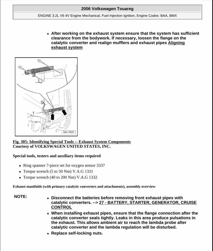
Fig. 305: Identifying Special Tools -- Exhaust System Components Courtesy of VOLKSWAGEN UNITED STATES, INC.
Special tools, testers and auxiliary items required
Ring spanner 7-piece set for oxygen sensor 3337
Torque wrench (5 to 50 Nm) V.A.G 1331
Torque wrench (40 to 200 Nm) V.A.G 1332
Exhaust manifolds (with primary catalytic converters and attachments), assembly overview
After working on the exhaust system ensure that the system has sufficient clearance from the bodywork. If necessary, loosen the flange on the catalytic converter and realign mufflers and exhaust pipes Aligning exhaust system
NOTE: Disconnect the batteries before removing front exhaust pipes with catalytic converters. --> 27 - BATTERY, STARTER, GENERATOR, CRUISE CONTROL
When installing exhaust pipes, ensure that the flange connection after the catalytic converter seals tightly. Leaks in this area produce pulsations in the exhaust. This allows ambient air to reach the lambda probe after catalytic converter and the lambda regulation will be disturbed.
Replace self-locking nuts.
2006 Volkswagen Touareg
ENGINE 3.2L V6 4V Engine Mechanical, Fuel Injection Ignition, Engine Codes: BAA, BMX
Microsoft
Sunday, September 20, 2009 9:14:20 AM Page 258 © 2005 Mitchell Repair Information Company, LLC.
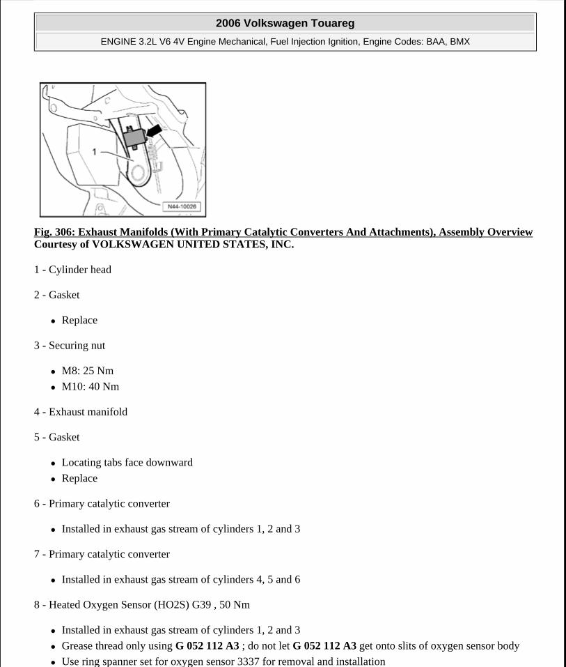
Fig. 306: Exhaust Manifolds (With Primary Catalytic Converters And Attachments), Assembly OverviewCourtesy of VOLKSWAGEN UNITED STATES, INC.
1 - Cylinder head
2 - Gasket
Replace
3 - Securing nut
M8: 25 Nm
M10: 40 Nm
4 - Exhaust manifold
5 - Gasket
Locating tabs face downward
Replace
6 - Primary catalytic converter
Installed in exhaust gas stream of cylinders 1, 2 and 3
7 - Primary catalytic converter
Installed in exhaust gas stream of cylinders 4, 5 and 6
8 - Heated Oxygen Sensor (HO2S) G39 , 50 Nm
Installed in exhaust gas stream of cylinders 1, 2 and 3
Grease thread only using G 052 112 A3 ; do not let G 052 112 A3 get onto slits of oxygen sensor body
Use ring spanner set for oxygen sensor 3337 for removal and installation
2006 Volkswagen Touareg
ENGINE 3.2L V6 4V Engine Mechanical, Fuel Injection Ignition, Engine Codes: BAA, BMX
Microsoft
Sunday, September 20, 2009 9:14:20 AM Page 259 © 2005 Mitchell Repair Information Company, LLC.
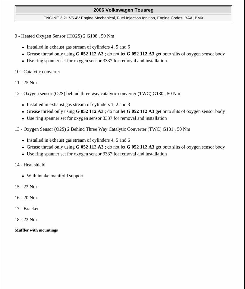
9 - Heated Oxygen Sensor (HO2S) 2 G108 , 50 Nm
Installed in exhaust gas stream of cylinders 4, 5 and 6
Grease thread only using G 052 112 A3 ; do not let G 052 112 A3 get onto slits of oxygen sensor body
Use ring spanner set for oxygen sensor 3337 for removal and installation
10 - Catalytic converter
11 - 25 Nm
12 - Oxygen sensor (O2S) behind three way catalytic converter (TWC) G130 , 50 Nm
Installed in exhaust gas stream of cylinders 1, 2 and 3
Grease thread only using G 052 112 A3 ; do not let G 052 112 A3 get onto slits of oxygen sensor body
Use ring spanner set for oxygen sensor 3337 for removal and installation
13 - Oxygen Sensor (O2S) 2 Behind Three Way Catalytic Converter (TWC) G131 , 50 Nm
Installed in exhaust gas stream of cylinders 4, 5 and 6
Grease thread only using G 052 112 A3 ; do not let G 052 112 A3 get onto slits of oxygen sensor body
Use ring spanner set for oxygen sensor 3337 for removal and installation
14 - Heat shield
With intake manifold support
15 - 23 Nm
16 - 20 Nm
17 - Bracket
18 - 23 Nm
Muffler with mountings
2006 Volkswagen Touareg
ENGINE 3.2L V6 4V Engine Mechanical, Fuel Injection Ignition, Engine Codes: BAA, BMX
Microsoft
Sunday, September 20, 2009 9:14:20 AM Page 260 © 2005 Mitchell Repair Information Company, LLC.
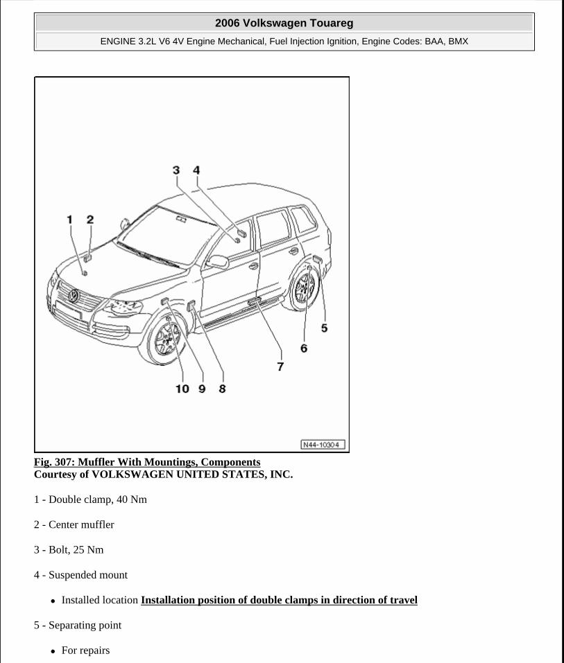
Fig. 307: Muffler With Mountings, Components Courtesy of VOLKSWAGEN UNITED STATES, INC.
1 - Double clamp, 40 Nm
2 - Center muffler
3 - Bolt, 25 Nm
4 - Suspended mount
Installed location Installation position of double clamps in direction of travel
5 - Separating point
For repairs
2006 Volkswagen Touareg
ENGINE 3.2L V6 4V Engine Mechanical, Fuel Injection Ignition, Engine Codes: BAA, BMX
Microsoft
Sunday, September 20, 2009 9:14:20 AM Page 261 © 2005 Mitchell Repair Information Company, LLC.
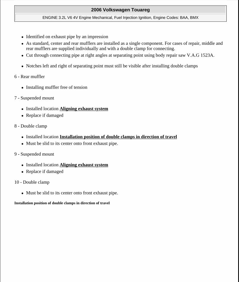
Identified on exhaust pipe by an impression
As standard, center and rear mufflers are installed as a single component. For cases of repair, middle and rear mufflers are supplied individually and with a double clamp for connecting.
Cut through connecting pipe at right angles at separating point using body repair saw V.A.G 1523A.
Notches left and right of separating point must still be visible after installing double clamps
6 - Rear muffler
Installing muffler free of tension
7 - Suspended mount
Installed location Aligning exhaust system
Replace if damaged
8 - Double clamp
Installed location Installation position of double clamps in direction of travel
Must be slid to its center onto front exhaust pipe.
9 - Suspended mount
Installed location Aligning exhaust system
Replace if damaged
10 - Double clamp
Must be slid to its center onto front exhaust pipe.
Installation position of double clamps in direction of travel
2006 Volkswagen Touareg
ENGINE 3.2L V6 4V Engine Mechanical, Fuel Injection Ignition, Engine Codes: BAA, BMX
Microsoft
Sunday, September 20, 2009 9:14:20 AM Page 262 © 2005 Mitchell Repair Information Company, LLC.
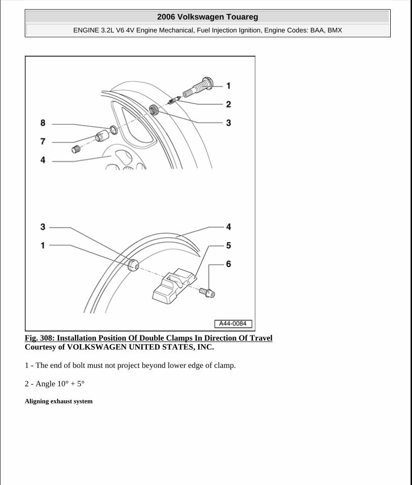
Fig. 308: Installation Position Of Double Clamps In Direction Of Travel Courtesy of VOLKSWAGEN UNITED STATES, INC.
1 - The end of bolt must not project beyond lower edge of clamp.
2 - Angle 10° + 5°
Aligning exhaust system
2006 Volkswagen Touareg
ENGINE 3.2L V6 4V Engine Mechanical, Fuel Injection Ignition, Engine Codes: BAA, BMX
Microsoft
Sunday, September 20, 2009 9:14:20 AM Page 263 © 2005 Mitchell Repair Information Company, LLC.
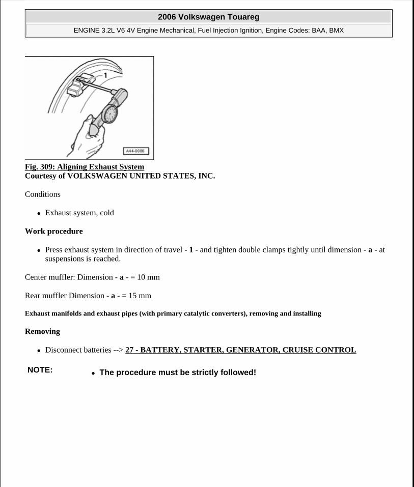
Fig. 309: Aligning Exhaust System Courtesy of VOLKSWAGEN UNITED STATES, INC.
Conditions
Exhaust system, cold
Work procedure
Press exhaust system in direction of travel - 1 - and tighten double clamps tightly until dimension - a - at suspensions is reached.
Center muffler: Dimension - a - = 10 mm
Rear muffler Dimension - a - = 15 mm
Exhaust manifolds and exhaust pipes (with primary catalytic converters), removing and installing
Removing
Disconnect batteries --> 27 - BATTERY, STARTER, GENERATOR, CRUISE CONTROL
NOTE: The procedure must be strictly followed!
2006 Volkswagen Touareg
ENGINE 3.2L V6 4V Engine Mechanical, Fuel Injection Ignition, Engine Codes: BAA, BMX
Microsoft
Sunday, September 20, 2009 9:14:20 AM Page 264 © 2005 Mitchell Repair Information Company, LLC.
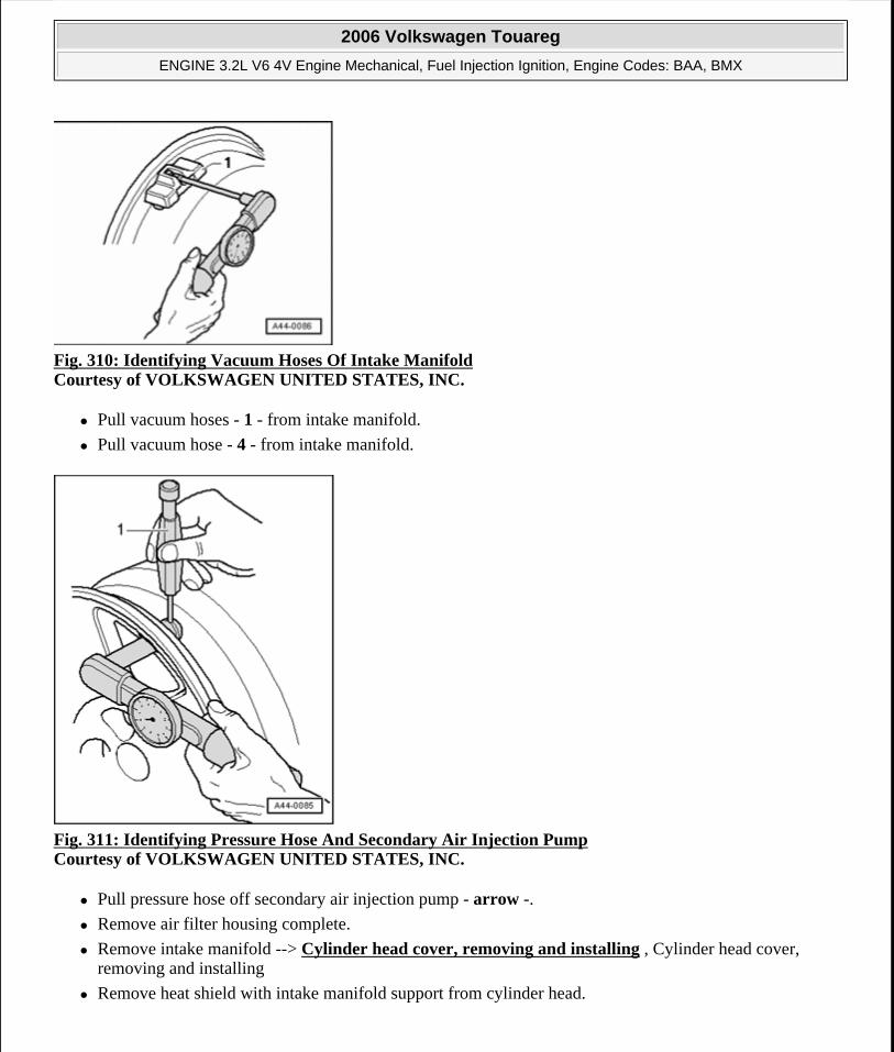
Fig. 310: Identifying Vacuum Hoses Of Intake Manifold Courtesy of VOLKSWAGEN UNITED STATES, INC.
Pull vacuum hoses - 1 - from intake manifold.
Pull vacuum hose - 4 - from intake manifold.
Fig. 311: Identifying Pressure Hose And Secondary Air Injection Pump Courtesy of VOLKSWAGEN UNITED STATES, INC.
Pull pressure hose off secondary air injection pump - arrow -.
Remove air filter housing complete.
Remove intake manifold --> Cylinder head cover, removing and installing , Cylinder head cover, removing and installing
Remove heat shield with intake manifold support from cylinder head.
2006 Volkswagen Touareg
ENGINE 3.2L V6 4V Engine Mechanical, Fuel Injection Ignition, Engine Codes: BAA, BMX
Microsoft
Sunday, September 20, 2009 9:14:20 AM Page 265 © 2005 Mitchell Repair Information Company, LLC.
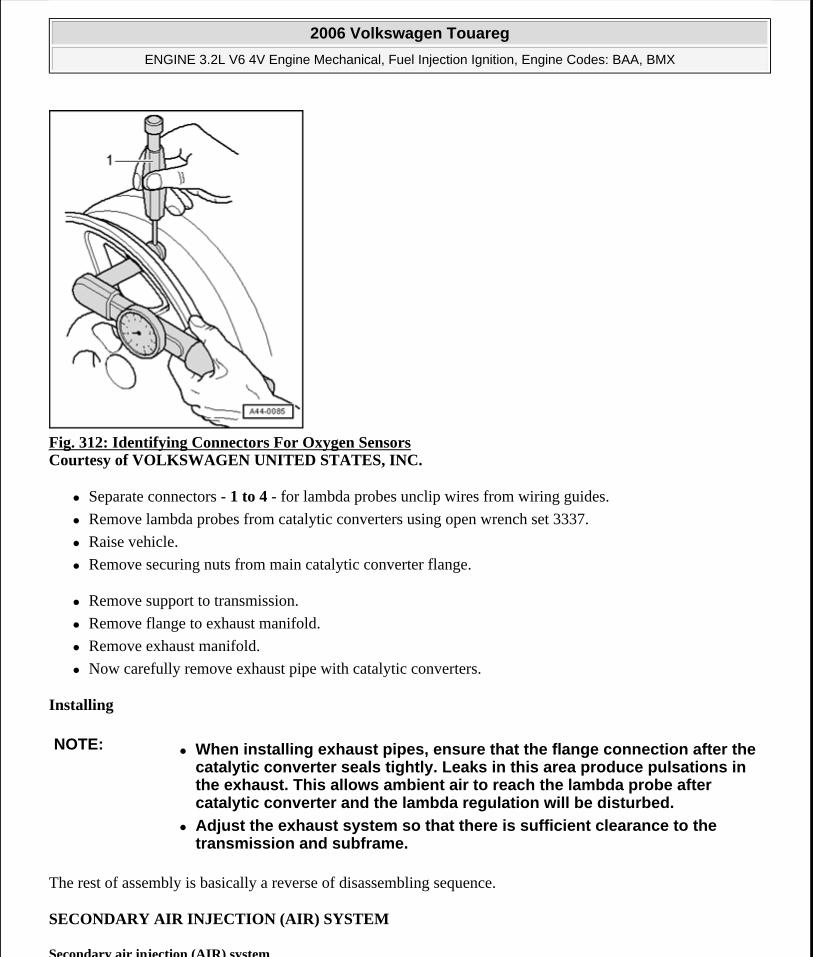
Fig. 312: Identifying Connectors For Oxygen Sensors Courtesy of VOLKSWAGEN UNITED STATES, INC.
Separate connectors - 1 to 4 - for lambda probes unclip wires from wiring guides.
Remove lambda probes from catalytic converters using open wrench set 3337.
Raise vehicle.
Remove securing nuts from main catalytic converter flange.
Remove support to transmission.
Remove flange to exhaust manifold.
Remove exhaust manifold.
Now carefully remove exhaust pipe with catalytic converters.
Installing
The rest of assembly is basically a reverse of disassembling sequence.
SECONDARY AIR INJECTION (AIR) SYSTEM
Secondary air injection (AIR) system
NOTE: When installing exhaust pipes, ensure that the flange connection after the catalytic converter seals tightly. Leaks in this area produce pulsations in the exhaust. This allows ambient air to reach the lambda probe after catalytic converter and the lambda regulation will be disturbed.
Adjust the exhaust system so that there is sufficient clearance to the transmission and subframe.
2006 Volkswagen Touareg
ENGINE 3.2L V6 4V Engine Mechanical, Fuel Injection Ignition, Engine Codes: BAA, BMX
Microsoft
Sunday, September 20, 2009 9:14:20 AM Page 266 © 2005 Mitchell Repair Information Company, LLC.
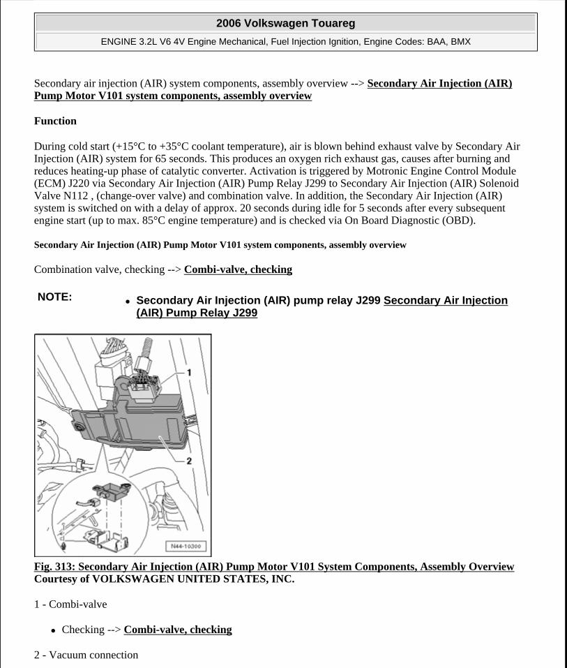
Secondary air injection (AIR) system components, assembly overview --> Secondary Air Injection (AIR) Pump Motor V101 system components, assembly overview
Function
During cold start (+15°C to +35°C coolant temperature), air is blown behind exhaust valve by Secondary Air Injection (AIR) system for 65 seconds. This produces an oxygen rich exhaust gas, causes after burning and reduces heating-up phase of catalytic converter. Activation is triggered by Motronic Engine Control Module (ECM) J220 via Secondary Air Injection (AIR) Pump Relay J299 to Secondary Air Injection (AIR) Solenoid Valve N112 , (change-over valve) and combination valve. In addition, the Secondary Air Injection (AIR) system is switched on with a delay of approx. 20 seconds during idle for 5 seconds after every subsequent engine start (up to max. 85°C engine temperature) and is checked via On Board Diagnostic (OBD).
Secondary Air Injection (AIR) Pump Motor V101 system components, assembly overview
Combination valve, checking --> Combi-valve, checking
Fig. 313: Secondary Air Injection (AIR) Pump Motor V101 System Components, Assembly Overview Courtesy of VOLKSWAGEN UNITED STATES, INC.
1 - Combi-valve
Checking --> Combi-valve, checking
2 - Vacuum connection
NOTE: Secondary Air Injection (AIR) pump relay J299 Secondary Air Injection (AIR) Pump Relay J299
2006 Volkswagen Touareg
ENGINE 3.2L V6 4V Engine Mechanical, Fuel Injection Ignition, Engine Codes: BAA, BMX
Microsoft
Sunday, September 20, 2009 9:14:20 AM Page 267 © 2005 Mitchell Repair Information Company, LLC.
3 - Gasket
Replace
4 - Connection
5 - 10 Nm
6 - Pressure pipe
7 - Bracket
8 - Stud, 8 Nm
Installed into intake manifold
9 - To Intake manifold
10 - To combi-valve
11 - to vacuum actuator
for variable intake manifold
12 - Non-return valve
Note installation position
White connector faces vacuum reservoir
13 - Intake Manifold Tuning (IMT) Valve N156
14 - 8 Nm
15 - Secondary air injection (AIR) solenoid valve N112
16 - To vacuum reservoir
17 - Pressure hose
Ensure seated tightly
Press together at front to release
18 - Secondary Air Injection (AIR) Pump Motor V101
19 - 10 Nm
2006 Volkswagen Touareg
ENGINE 3.2L V6 4V Engine Mechanical, Fuel Injection Ignition, Engine Codes: BAA, BMX
Microsoft
Sunday, September 20, 2009 9:14:20 AM Page 268 © 2005 Mitchell Repair Information Company, LLC.
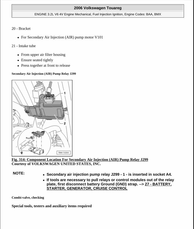
20 - Bracket
For Secondary Air Injection (AIR) pump motor V101
21 - Intake tube
From upper air filter housing
Ensure seated tightly
Press together at front to release
Secondary Air Injection (AIR) Pump Relay J299
Fig. 314: Component Location For Secondary Air Injection (AIR) Pump Relay J299 Courtesy of VOLKSWAGEN UNITED STATES, INC.
Combi-valve, checking
Special tools, testers and auxiliary items required
NOTE: Secondary air injection pump relay J299 - 1 - is inserted in socket A4.
If tools are necessary to pull relays or control modules out of the relay plate, first disconnect battery Ground (GND) strap. --> 27 - BATTERY, STARTER, GENERATOR, CRUISE CONTROL
2006 Volkswagen Touareg
ENGINE 3.2L V6 4V Engine Mechanical, Fuel Injection Ignition, Engine Codes: BAA, BMX
Microsoft
Sunday, September 20, 2009 9:14:20 AM Page 269 © 2005 Mitchell Repair Information Company, LLC.
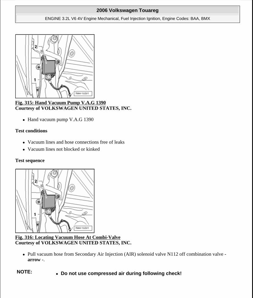
Fig. 315: Hand Vacuum Pump V.A.G 1390 Courtesy of VOLKSWAGEN UNITED STATES, INC.
Hand vacuum pump V.A.G 1390
Test conditions
Vacuum lines and hose connections free of leaks
Vacuum lines not blocked or kinked
Test sequence
Fig. 316: Locating Vacuum Hose At Combi-Valve Courtesy of VOLKSWAGEN UNITED STATES, INC.
Pull vacuum hose from Secondary Air Injection (AIR) solenoid valve N112 off combination valve - arrow -.
NOTE: Do not use compressed air during following check!
2006 Volkswagen Touareg
ENGINE 3.2L V6 4V Engine Mechanical, Fuel Injection Ignition, Engine Codes: BAA, BMX
Microsoft
Sunday, September 20, 2009 9:14:20 AM Page 270 © 2005 Mitchell Repair Information Company, LLC.
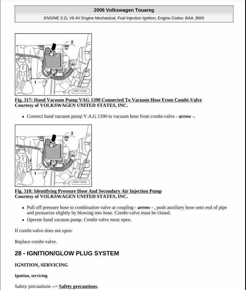
Fig. 317: Hand Vacuum Pump VAG 1390 Connected To Vacuum Hose From Combi-Valve Courtesy of VOLKSWAGEN UNITED STATES, INC.
Connect hand vacuum pump V.A.G 1390 to vacuum hose from combi-valve - arrow -.
Fig. 318: Identifying Pressure Hose And Secondary Air Injection Pump Courtesy of VOLKSWAGEN UNITED STATES, INC.
Pull off pressure hose to combination valve at coupling - arrow - , push auxiliary hose onto end of pipe and pressurize slightly by blowing into hose. Combi-valve must be closed.
Operate hand vacuum pump. Combi-valve must open.
If combi-valve does not open:
Replace combi-valve.
28 - IGNITION/GLOW PLUG SYSTEM
IGNITION, SERVICING
Ignition, servicing
Safety precautions --> Safety precautions.
2006 Volkswagen Touareg
ENGINE 3.2L V6 4V Engine Mechanical, Fuel Injection Ignition, Engine Codes: BAA, BMX
Microsoft
Sunday, September 20, 2009 9:14:20 AM Page 271 © 2005 Mitchell Repair Information Company, LLC.
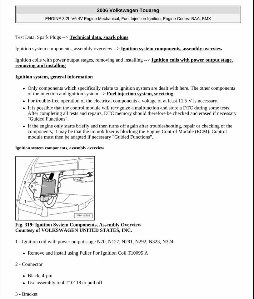
Test Data, Spark Plugs --> Technical data, spark plugs.
Ignition system components, assembly overview --> Ignition system components, assembly overview
Ignition coils with power output stages, removing and installing --> Ignition coils with power output stage, removing and installing
Ignition system, general information
Only components which specifically relate to ignition system are dealt with here. The other components of the injection and ignition system --> Fuel injection system, servicing.
For trouble-free operation of the electrical components a voltage of at least 11.5 V is necessary.
It is possible that the control module will recognize a malfunction and store a DTC during some tests. After completing all tests and repairs, DTC memory should therefore be checked and erased if necessary "Guided Functions".
If the engine only starts briefly and then turns off again after troubleshooting, repair or checking of the components, it may be that the immobilizer is blocking the Engine Control Module (ECM). Control module must then be adapted if necessary "Guided Functions".
Ignition system components, assembly overview
Fig. 319: Ignition System Components, Assembly Overview Courtesy of VOLKSWAGEN UNITED STATES, INC.
1 - Ignition coil with power output stage N70, N127, N291, N292, N323, N324
Remove and install using Puller For Ignition Coil T10095 A
2 - Connector
Black, 4-pin
Use assembly tool T10118 to pull off
3 - Bracket
2006 Volkswagen Touareg
ENGINE 3.2L V6 4V Engine Mechanical, Fuel Injection Ignition, Engine Codes: BAA, BMX
Microsoft
Sunday, September 20, 2009 9:14:20 AM Page 272 © 2005 Mitchell Repair Information Company, LLC.
For harness connector of Knock Sensor (KS) 1 G61
4 - 10 Nm
5 - Connector
Black, 3-pin
Sensor contacts and connector contacts gold plated
6 - Knock Sensor (KS) 1 G61
Component location: Between cyl. 1 and cyl. 3
7 - 20 Nm
Torque setting influences function of knock sensor
8 - Exhaust camshaft adjuster
Identification: 32A
With sensor wheel for Camshaft Position (CMP) Sensor 2 G163
If camshaft adjuster has been removed, adjust valve timing after installation --> Valve timing, adjusting.
9 - Cover
Removing and installing --> Cover, removing and installing, assembly overview.
10 - Seal
Replace
11 - Camshaft position (CMP) sensor 2 G163
For exhaust camshaft
Sensor contacts and connector contacts gold plated
12 - 10 Nm
13 - Connector
Black, 3-pin
Sensor contacts and connector contacts gold plated
Mark connector before removing
14 - Camshaft Position (CMP) sensor G40
2006 Volkswagen Touareg
ENGINE 3.2L V6 4V Engine Mechanical, Fuel Injection Ignition, Engine Codes: BAA, BMX
Microsoft
Sunday, September 20, 2009 9:14:20 AM Page 273 © 2005 Mitchell Repair Information Company, LLC.
For intake camshaft
Sensor contacts and connector contacts gold plated
15 - Knock Sensor (KS) 2 G66
Component location: Between cyl. 4 and cyl. 6
Sensor contacts and connector contacts gold plated
16 - Connector
Black, 2-pin
Sensor contacts and connector contacts gold plated
17 - Intake camshaft adjuster
Identification: 24E
With sensor wheel for Camshaft Position (CMP) Sensor G40
If camshaft adjuster has been removed, adjust valve timing after installation --> Valve timing, adjusting.
18 - Spark plug, 20 Nm
Removing and installing with spark plug removal tool 3122B
Type and electrode gap --> Technical data, spark plugs
19 - Control housing
Camshaft adjustment valves, removing and installing --> Camshaft adjustment valves, removing and installing
Removing and installing --> Camshafts, removing and installing , camshafts, removing and installing
Safety precautions
To reduce risk of personal injury and/or damage to fuel injection and ignition system, always observe the following:
Only disconnect and reconnect wires for injection and ignition system, including test leads, when ignition is switched off.
Do not touch or remove ignition wires when engine is running or turning at starter speed.
If test and measuring equipment is required during road test, note the following:
Test and measuring instruments must be secured to rear seat and operated by a 2nd person from this location.
2006 Volkswagen Touareg
ENGINE 3.2L V6 4V Engine Mechanical, Fuel Injection Ignition, Engine Codes: BAA, BMX
Microsoft
Sunday, September 20, 2009 9:14:20 AM Page 274 © 2005 Mitchell Repair Information Company, LLC.
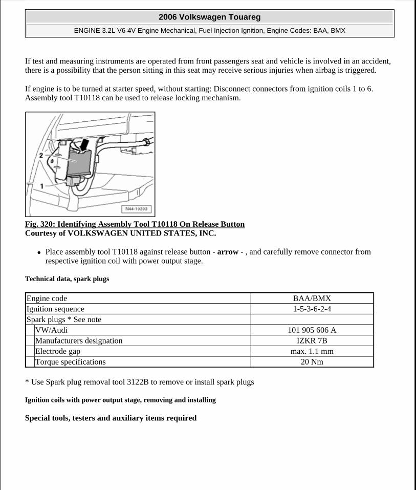
If test and measuring instruments are operated from front passengers seat and vehicle is involved in an accident, there is a possibility that the person sitting in this seat may receive serious injuries when airbag is triggered.
If engine is to be turned at starter speed, without starting: Disconnect connectors from ignition coils 1 to 6. Assembly tool T10118 can be used to release locking mechanism.
Fig. 320: Identifying Assembly Tool T10118 On Release Button Courtesy of VOLKSWAGEN UNITED STATES, INC.
Place assembly tool T10118 against release button - arrow - , and carefully remove connector from respective ignition coil with power output stage.
Technical data, spark plugs
* Use Spark plug removal tool 3122B to remove or install spark plugs
Ignition coils with power output stage, removing and installing
Special tools, testers and auxiliary items required
Engine code BAA/BMXIgnition sequence 1-5-3-6-2-4Spark plugs * See note VW/Audi 101 905 606 A Manufacturers designation IZKR 7B Electrode gap max. 1.1 mm Torque specifications 20 Nm
2006 Volkswagen Touareg
ENGINE 3.2L V6 4V Engine Mechanical, Fuel Injection Ignition, Engine Codes: BAA, BMX
Microsoft
Sunday, September 20, 2009 9:14:20 AM Page 275 © 2005 Mitchell Repair Information Company, LLC.
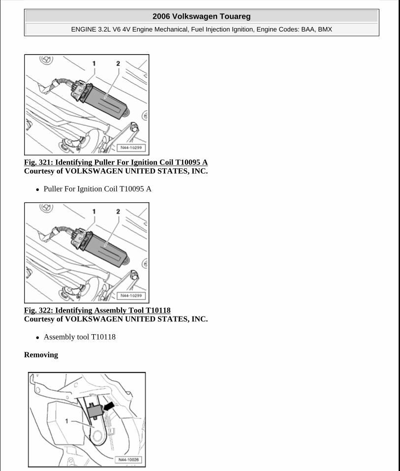
Fig. 321: Identifying Puller For Ignition Coil T10095 A Courtesy of VOLKSWAGEN UNITED STATES, INC.
Puller For Ignition Coil T10095 A
Fig. 322: Identifying Assembly Tool T10118 Courtesy of VOLKSWAGEN UNITED STATES, INC.
Assembly tool T10118
Removing
2006 Volkswagen Touareg
ENGINE 3.2L V6 4V Engine Mechanical, Fuel Injection Ignition, Engine Codes: BAA, BMX
Microsoft
Sunday, September 20, 2009 9:14:20 AM Page 276 © 2005 Mitchell Repair Information Company, LLC.
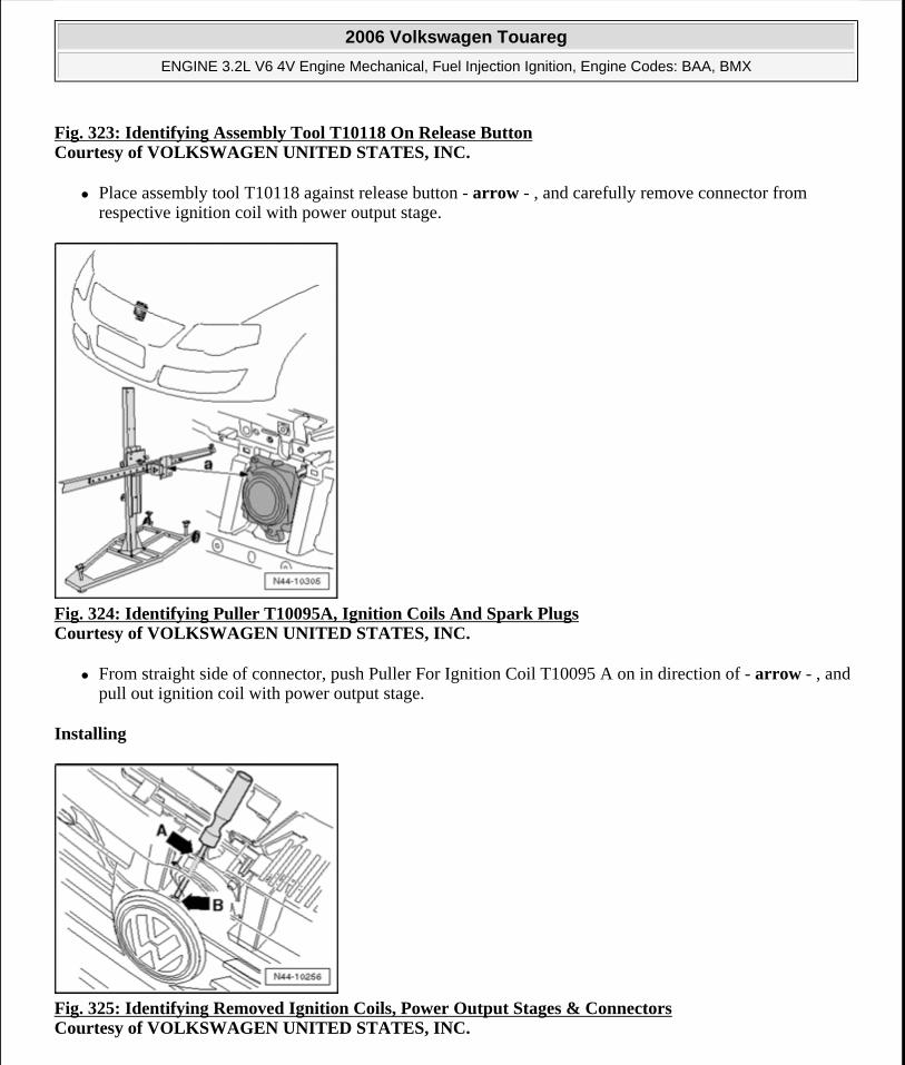
Fig. 323: Identifying Assembly Tool T10118 On Release ButtonCourtesy of VOLKSWAGEN UNITED STATES, INC.
Place assembly tool T10118 against release button - arrow - , and carefully remove connector from respective ignition coil with power output stage.
Fig. 324: Identifying Puller T10095A, Ignition Coils And Spark Plugs Courtesy of VOLKSWAGEN UNITED STATES, INC.
From straight side of connector, push Puller For Ignition Coil T10095 A on in direction of - arrow - , and pull out ignition coil with power output stage.
Installing
Fig. 325: Identifying Removed Ignition Coils, Power Output Stages & Connectors Courtesy of VOLKSWAGEN UNITED STATES, INC.
2006 Volkswagen Touareg
ENGINE 3.2L V6 4V Engine Mechanical, Fuel Injection Ignition, Engine Codes: BAA, BMX
Microsoft
Sunday, September 20, 2009 9:14:20 AM Page 277 © 2005 Mitchell Repair Information Company, LLC.
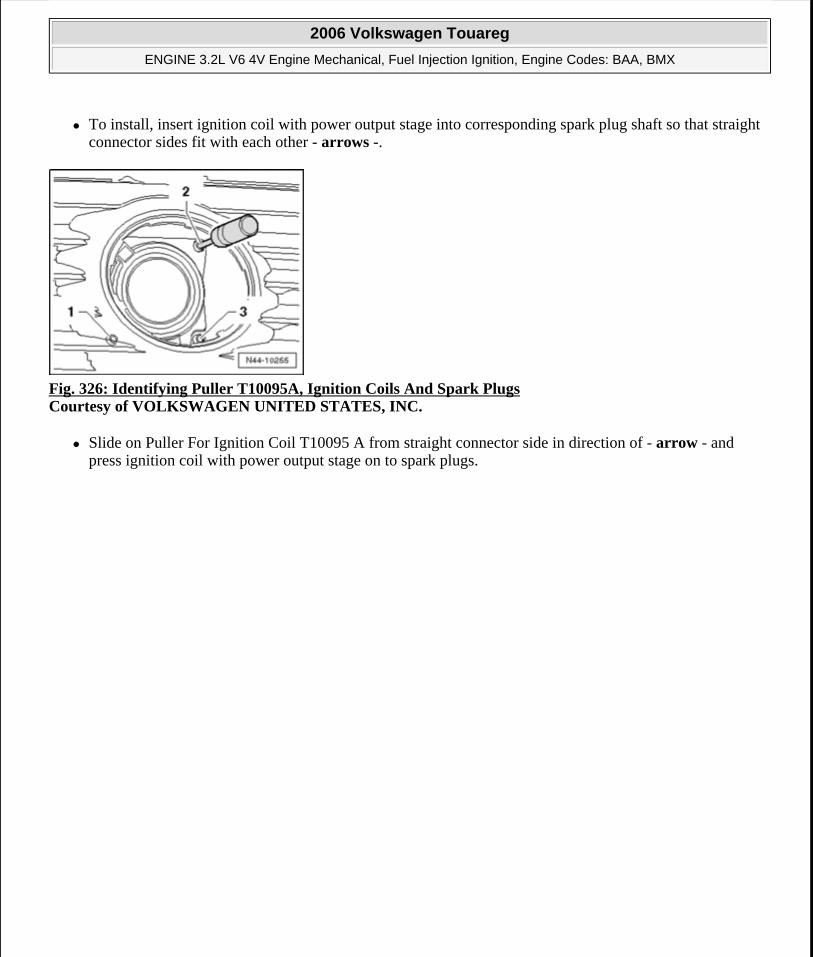
To install, insert ignition coil with power output stage into corresponding spark plug shaft so that straight connector sides fit with each other - arrows -.
Fig. 326: Identifying Puller T10095A, Ignition Coils And Spark Plugs Courtesy of VOLKSWAGEN UNITED STATES, INC.
Slide on Puller For Ignition Coil T10095 A from straight connector side in direction of - arrow - and press ignition coil with power output stage on to spark plugs.
2006 Volkswagen Touareg
ENGINE 3.2L V6 4V Engine Mechanical, Fuel Injection Ignition, Engine Codes: BAA, BMX
Microsoft
Sunday, September 20, 2009 9:14:20 AM Page 278 © 2005 Mitchell Repair Information Company, LLC.