Embed Size (px)
Citation preview

GE Consumer & Industrial Power Protection
Technical Data Sheets Digital Energy™ Uninterruptible Power Supply LP 33 Series / 10 – 20 – 30 – 40 – 50 – 60 kVA 208 VAC UL – Series 0 Date of issue: 05/15/2007
LPS33U_030-040_UPS_GE_01
Dig ital EnergyT M
LP S erie s
LPS33U_050-060_UPS_GE_01
Dig ital E nergyT M
LP S eries
LP 33 Series / 10 & 20 kVA LP 33 Series / 30 & 40 kVA LP 33 Series / 50 & 60 kVA GE Consumer & Industrial SA General Electric Company CH – 6595 Riazzino (Locarno) Switzerland T +41 (0)91 / 850 51 51 F +41 (0)91 / 850 51 44
www.gedigitalenergy.com
GE imagination at work

Modifications reserved Page 2/6 TDS_LPS_33U_10K_60K_0US_V010.doc Technical Data Sheets LP 33 Series 10-20-30-40-50-60 kVA
GENERAL DATA Topology VFI, double conversion Nominal output apparent power kVA 10 kVA 20 kVA 30 kVA 40 kVA 50 kVA 60 kVA Power factor (output) PF 0.8 lag. 0.9 lag. Nominal output active power kW 8 16 24 32 45 54 Overall efficiency at 100% load in VFI mode % 90.0 90.0 90.6 90.5 90.2 90.0 Overall efficiency at 100% load in ECO mode % 98.0 98.0 99.0 99.0 98.0 98.0 Heat dissipation at 100% load in VFI mode, nominal PF and charged battery kW 0.89 1.78 2.49 3.36 4.89 6.00
Cooling air (77°F...86°F / 25°C...30°C) CFM 154 308 431 582 847 1040 Audible noise level dB(A) 50 55 61 62 65 65 Battery type Valve regulated lead-acid (VRLA)
Operating temperature range UPS: 32°F ÷ 104°F (0°C ÷ 40°C) Battery: 68°F ÷ 77°F 20°C ÷ 25°C) recommended
Storage temperature range -13°F ÷ 131°F (-25°C ÷ +55°C) Storage time of the battery without recharge at 68°F (20°C) Max. 6 months Relative humidity Max. 95% (non-condensing) Max. altitude without power derating Power derating (according to IEC 62040-3)
3300 ft 5000 ft: 95% / 6500 ft: 91% / 8200 ft: 86% / 9800 ft: 82%
Protection degree IP 20 (IEC 60529) and NEMA-PE-1 Safety Standards UL 1778, IEC 62040, ISO 9001 EMC FCC Class A, IEC 62040-2 Class A Electrostatic discharge immunity 4kV contact / 8kV air discharge Internal protection All live parts shrouded Enclosure Metal sheet and castors
Transport 10 & 20 kVA: Packaging suitable for handling by forklift 30 to 60 kVA: Cabinet and packaging suitable for handling by forklift
Color RAL 9003 (white)
Installation 10 & 20 kVA: Minimum distance from the wall 2 inches (5 cm) 30 to 60 kVA: Can be positioned against a wall and floor
Service access Front and top External cable connections Front Bottom conduit access Cooling Forced to top by internal blower
Paralleling (RPA version) Up to 4 units in parallel for redundancy or capacity in RPAconfiguration (optional)
RECTIFIER Rectifier bridge Three phase, over temperature protection
Standard input voltage
Nominal: 3 x 208 + N 10 & 20 kVA: -25% ÷ +20% 30 & 40 kVA: -20% ÷ +15% 50 & 60 kVA: -15% ÷ +10%
Input frequency 60 Hz +/-10% Input power factor >0.98 lag.
Input current distortion (THDI) 10 & 20 kVA: <8% 30 to 60 kVA: <10%
Output voltage tolerance +/- 1% Battery ripple current Max. 5% of the battery capacity [Ah], expressed in A Battery charging characteristic IU (DIN 41773), T° compensated floating voltage
Battery charging current limit 10 & 20 kVA: settable in 3 steps 30 to 60 kVA: settable by parameter
Input power data kVA 10 kVA 20 kVA 30 kVA 40 kVA 50 kVA 60 kVA Nominal input at inverter nominal load, and charged battery Current (A) 25.2 50.4 75.1 100 141 170
KVA 9.1 18.1 27.0 36.1 50.9 61.2 kW 8.9 17.8 26.5 35.4 49.9 60.0 Max. input power at inverter nominal load and max. battery recharge current (programmable) Current (A) 27.4 54.7 87.3 113 155 183
KVA 9.9 19.7 31.4 40.5 55.6 65.9 kW 9.7 19.3 30.8 39.7 54.5 64.6 Max. battery charging current (programmable) A 2.4 4.8 15.0 15.0 16.0 16.0 Battery boostcharge Yes (selectable)
Modifications reserved Page 3/6 TDS_LPS_33U_10K_60K_0US_V010.doc Technical Data Sheets LP 33 Series 10-20-30-40-50-60 kVA
BATTERY Battery type Standard: Valve regulated lead-acid (VRLA) Number of blocks and battery capacity See battery table on page 5 and 6 Float voltage at 20°C 2 x 164 VDC Min. discharge voltage (programmable) 2 x 118 VDC Recharge time 6 ÷ 8 hours Automatic and manual battery test Standard Common battery in parallel system Up to 4 units (only for 30 to 60 kVA) Battery power data kVA 10 kVA 20 kVA 30 kVA 40 kVA 50 kVA 60 kVA DC power at full load and nominal PF kW 8. 9 17.8 26.5 35.4 49.9 60.0 Max discharge current at 100% load and nominal PF A 38 75 112 150 211 254 Matching battery cabinets See optional features on page 4
INVERTER Nominal output power at PF=0.6 ... 0.8 lag. / 0.6 ... 0.9 lag. 10 to 40 kVA / 50 & 60 kVA Nominal output voltage (on site programmable) 3 x 208V+ N Inverter bridge IGBT technology Output waveform Sine wave Output voltage tolerance: - static ................................................................................................................ +/- 1% - dynamic (at load step 0 – 100 – 0%) ................................................. +/- 1% - recovery time to +/-1% ........................................................................... <3 ms
10 kVA 20 kVA 30 kVA 40 kVA 50 kVA 60 kVA - output voltage THD for 100% linear load ....................................... <2% <2% <1.5% <1.5% <2% <2% - output voltage THD for 100% non-linear load (EN 50091) <3% Output voltage tolerance at 100% unbalanced load (Ph-N) +/- 3% Output frequency 60 Hz Output frequency tolerance: - free-running ................................................................................................. +/- 0.1% - with mains synchronisation adjustable to...................................... +/- 4% Phase displacement: - at 100% balanced load ........................................................................... 120°: +/- 1% - at 100% unbalanced load...................................................................... 120°: +/- 2% Overload capability (at nominal PF) 125% - 10 minutes, 150% - 1 minute
Short-circuit characteristic Electronic short-circuit protection, current limit to 2.2 times In for 100 ms
10 kVA 20 kVA 30 kVA 40 kVA 50 kVA 60 kVA Nominal output current at full load 28A 56A 83A 111A 139A 167A Crest factor >3:1
BYPASS
Input connection - Common input (Rectifier & Bypass) - Dual input (optional)
Primary components
- Thyristors (SSM – Static Switch module) - Electromechanical contactors (backfeed protection) on
bypass and inverter - 2 manual switches for maintenance bypass
Voltage limits for inverter/bypass load transfers +/- 15% 200% for 2 Minutes
Overload on bypass 2000% for ½ cycle, non repetitive
INTERFACING
Potential free contacts - 4 (Utility failure, General alarm, Stop operation, load on utility) - 28 user settable signals
Serial channel RS232 (on Delta 9 pin connector) Standard EPO (Emergency Power Off) Standard
Extended Customer Interface Card (optional) - EMERGENCY POWER OFF (n/c contact, customer supplied) - 6 potential free alarm contacts - 2 auxiliary contacts (one default configured as Genset)
Note: all indicated values are typical. Variations may be found from one unit to another.
Modifications reserved Page 4/6 TDS_LPS_33U_10K_60K_0US_V010.doc Technical Data Sheets LP 33 Series 10-20-30-40-50-60 kVA
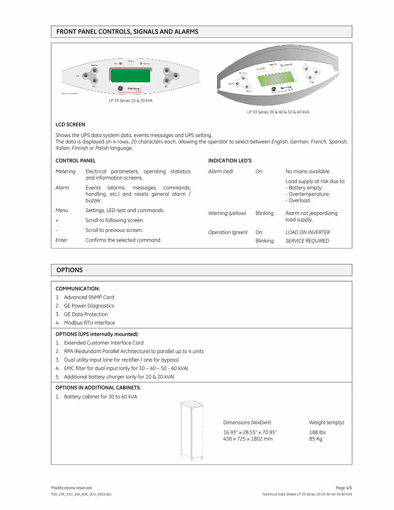
FRONT PANEL CONTROLS, SIGNALS AND ALARMS
LP 33 Series 10 & 20 kVA
LP 33 Series 30 & 40 & 50 & 60 kVA
LCD SCREEN
Shows the UPS data system data, events messages and UPS setting. The data is displayed on 4 rows, 20 characters each, allowing the operator to select between English, German, French, Spanish, Italian, Finnish or Polish language.
CONTROL PANEL
Metering Electrical parameters, operating statistics and information screens.
Alarm Events (alarms, messages, commands, handling, etc.) and resets general alarm / buzzer.
Menu Settings, LED-test and commands.
+ Scroll to following screen.
- Scroll to previous screen.
Enter Confirms the selected command.
INDICATION LED’S
Alarm (red) On: No mains available.
Load supply at risk due to: - Battery empty; - Overtemperature; - Overload. Warning (yellow) Blinking: Alarm not jeopardizing
load supply. Operation (green) On: LOAD ON INVERTER
Blinking: SERVICE REQUIRED
OPTIONS
COMMUNICATION:
1. Advanced SNMP Card
2. GE Power Diagnostics
3. GE Data Protection
4. Modbus RTU Interface
OPTIONS (UPS internally mounted):
1. Extended Customer Interface Card
2. RPA (Redundant Parallel Architecture) to parallel up to 4 units
3. Dual utility input (one for rectifier / one for bypass)
4. EMC filter for dual input (only for 30 – 40 – 50 - 60 kVA)
5. Additional battery charger (only for 10 & 20 kVA)
OPTIONS IN ADDITIONAL CABINETS:
1. Battery cabinet for 30 to 60 kVA
LPS33U_OPT_Cabinet battery_01
Dimensions (WxDxH):
16.93” x 28.55” x 70.95” 430 x 725 x 1802 mm
Weight (empty):
188 lbs 85 Kg
Modifications reserved Page 5/6 TDS_LPS_33U_10K_60K_0US_V010.doc Technical Data Sheets LP 33 Series 10-20-30-40-50-60 kVA
TECHNICAL DATA
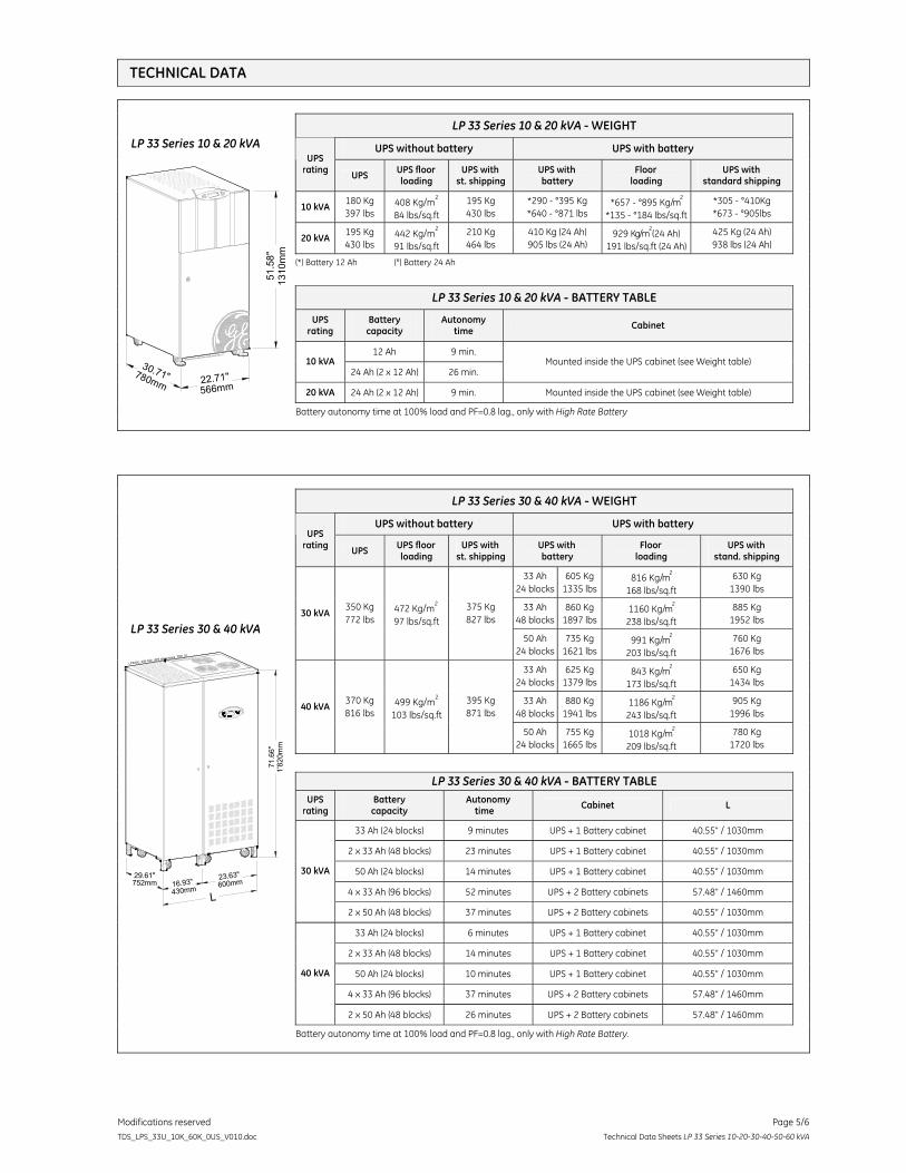
LP 33 Series 10 & 20 kVA - WEIGHT
UPS without battery UPS with battery UPS
rating UPS UPS floor loading
UPS with st. shipping
UPS with battery
Floor loading
UPS with standard shipping
10 kVA 180 Kg 397 lbs
408 Kg/m2
84 lbs/sq.ft 195 Kg 430 lbs
*290 - °395 Kg *640 - °871 lbs
*657 - °895 Kg/m2
*135 - °184 lbs/sq.ft *305 - °410Kg *673 - °905lbs
20 kVA 195 Kg 430 lbs
442 Kg/m2
91 lbs/sq.ft 210 Kg 464 lbs
410 Kg (24 Ah) 905 lbs (24 Ah)
929 Kg/m2 (24 Ah)
191 lbs/sq.ft (24 Ah) 425 Kg (24 Ah) 938 lbs (24 Ah)
(*) Battery 12 Ah (°) Battery 24 Ah
LP 33 Series 10 & 20 kVA - BATTERY TABLE
UPS rating
Battery capacity
Autonomy time Cabinet
12 Ah 9 min. 10 kVA
24 Ah (2 x 12 Ah) 26 min. Mounted inside the UPS cabinet (see Weight table)
20 kVA 24 Ah (2 x 12 Ah) 9 min. Mounted inside the UPS cabinet (see Weight table)
LP 33 Series 10 & 20 kVA
1310
mm
566mm780mm
51.5
8"
22.71"30.71"
Battery autonomy time at 100% load and PF=0.8 lag., only with High Rate Battery
LP 33 Series 30 & 40 kVA - WEIGHT
UPS without battery UPS with battery UPS
rating UPS UPS floor loading
UPS with st. shipping
UPS with battery
Floor loading
UPS with stand. shipping
33 Ah 24 blocks
605 Kg 1335 lbs
816 Kg/m2
168 lbs/sq.ft 630 Kg
1390 lbs 33 Ah
48 blocks 860 Kg
1897 lbs 1160 Kg/m
2
238 lbs/sq.ft 885 Kg
1952 lbs 30 kVA
350 Kg 772 lbs
472 Kg/m2
97 lbs/sq.ft 375 Kg 827 lbs
50 Ah 24 blocks
735 Kg 1621 lbs
991 Kg/m2
203 lbs/sq.ft 760 Kg
1676 lbs 33 Ah
24 blocks 625 Kg
1379 lbs 843 Kg/m
2
173 lbs/sq.ft 650 Kg
1434 lbs 33 Ah
48 blocks 880 Kg
1941 lbs 1186 Kg/m
2
243 lbs/sq.ft 905 Kg
1996 lbs 40 kVA
370 Kg 816 lbs
499 Kg/m2
103 lbs/sq.ft 395 Kg 871 lbs
50 Ah 24 blocks
755 Kg 1665 lbs
1018 Kg/m2
209 lbs/sq.ft 780 Kg
1720 lbs
LP 33 Series 30 & 40 kVA - BATTERY TABLE
UPS rating
Battery capacity
Autonomy time Cabinet L
33 Ah (24 blocks) 9 minutes UPS + 1 Battery cabinet 40.55” / 1030mm
2 x 33 Ah (48 blocks) 23 minutes UPS + 1 Battery cabinet 40.55” / 1030mm 50 Ah (24 blocks) 14 minutes UPS + 1 Battery cabinet 40.55” / 1030mm
4 x 33 Ah (96 blocks) 52 minutes UPS + 2 Battery cabinets 57.48” / 1460mm
30 kVA
2 x 50 Ah (48 blocks) 37 minutes UPS + 2 Battery cabinets 40.55” / 1030mm 33 Ah (24 blocks) 6 minutes UPS + 1 Battery cabinet 40.55” / 1030mm
2 x 33 Ah (48 blocks) 14 minutes UPS + 1 Battery cabinet 40.55” / 1030mm 50 Ah (24 blocks) 10 minutes UPS + 1 Battery cabinet 40.55” / 1030mm
4 x 33 Ah (96 blocks) 37 minutes UPS + 2 Battery cabinets 57.48” / 1460mm
40 kVA
2 x 50 Ah (48 blocks) 26 minutes UPS + 2 Battery cabinets 57.48” / 1460mm
LP 33 Series 30 & 40 kVA
LPS33U_030-040_UPS dimensions_TDS_01
Digit al EnergyTM
LP Se ries
752mm
1'82
0mm
71.6
6"
29.61"
L600mm23.63"
430mm16.93"
Battery autonomy time at 100% load and PF=0.8 lag., only with High Rate Battery.
Modifications reserved Page 6/6 TDS_LPS_33U_10K_60K_0US_V010.doc Technical Data Sheets LP 33 Series 10-20-30-40-50-60 kVA
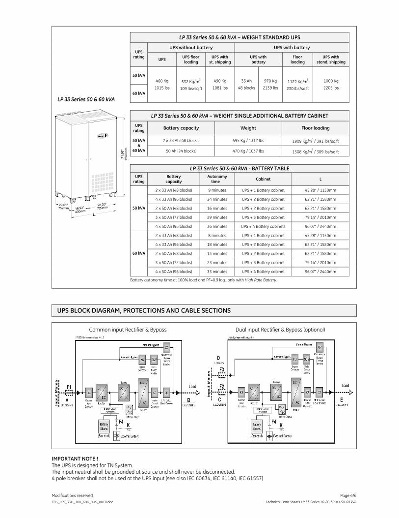
LP 33 Series 50 & 60 kVA – WEIGHT STANDARD UPS
UPS without battery UPS with battery UPS
rating UPS UPS floor loading
UPS with st. shipping
UPS with battery
Floor loading
UPS with stand. shipping
50 kVA
60 kVA
460 Kg
1015 lbs 532 Kg/m
2
109 lbs/sq.ft
490 Kg
1081 lbs
33 Ah
48 blocks
970 Kg
2139 lbs 1122 Kg/m
2
230 lbs/sq.ft
1000 Kg
2205 lbs
LP 33 Series 50 & 60 kVA – WEIGHT SINGLE ADDITIONAL BATTERY CABINET
UPS rating Battery capacity Weight Floor loading
2 x 33 Ah (48 blocks) 595 Kg / 1312 lbs 1909 Kg/m2 / 391 lbs/sq.ft 50 kVA
& 60 kVA 50 Ah (24 blocks) 470 Kg / 1037 lbs 1508 Kg/m
2 / 309 lbs/sq.ft
LP 33 Series 50 & 60 kVA - BATTERY TABLE
UPS rating
Battery capacity
Autonomy time Cabinet L
2 x 33 Ah (48 blocks) 9 minutes UPS + 1 Battery cabinet 45.28” / 1150mm 4 x 33 Ah (96 blocks) 24 minutes UPS + 2 Battery cabinet 62.21” / 1580mm 2 x 50 Ah (48 blocks) 16 minutes UPS + 2 Battery cabinet 62.21” / 1580mm 3 x 50 Ah (72 blocks) 29 minutes UPS + 3 Battery cabinet 79.14” / 2010mm
50 kVA
4 x 50 Ah (96 blocks) 36 minutes UPS + 4 Battery cabinets 96.07” / 2440mm 2 x 33 Ah (48 blocks) 8 minutes UPS + 1 Battery cabinet 45.28” / 1150mm 4 x 33 Ah (96 blocks) 18 minutes UPS + 2 Battery cabinet 62.21” / 1580mm 2 x 50 Ah (48 blocks) 13 minutes UPS + 2 Battery cabinet 62.21” / 1580mm 3 x 50 Ah (72 blocks) 23 minutes UPS + 3 Battery cabinet 79.14” / 2010mm
60 kVA
4 x 50 Ah (96 blocks) 33 minutes UPS + 4 Battery cabinet 96.07” / 2440mm
LP 33 Series 50 & 60 kVA
LPS33U_050-060_UPS dimension_TDS_01
Di gi ta l E nergyT M
LP S eries
752mm
1'82
0mm
71.6
6"
29.61"
L720mm28.35"
430mm16.93"
Battery autonomy time at 100% load and PF=0.9 lag., only with High Rate Battery.
UPS BLOCK DIAGRAM, PROTECTIONS AND CABLE SECTIONS
Common input Rectifier & Bypass Dual input Rectifier & Bypass (optional)
IMPORTANT NOTE ! The UPS is designed for TN System. The input neutral shall be grounded at source and shall never be disconnected. 4 pole breaker shall not be used at the UPS input (see also IEC 60634, IEC 61140, IEC 61557)