Embed Size (px)
Citation preview

Technical Data
8-11-2016 Page 1 of 7 KIWI REPORTER Technical Data Sheet V1.0.docx
KIWI REPORTER SCADA communication to Horstmann SMART NAVIGATORS
1. Introduction Overhead Fault Passage Indicators (FPIs) are used to indicate if a fault current has been detected at that point on the network. By using devices installed at strategic points of the network, lines staff can quickly identify the network section where a fault resides, thereby reducing the fault location time. The ‘KIWI REPORTER’ is a robust, pole mounted communications interface that works in conjunction with the Horstmann SMART NAVIGATOR series of visual overhead Fault Passage Indicators. The KIWI REPORTER provides the DNP interface to SCADA, communicating detailed information about fault events, fault locations and load data for line staff, network operators and performance engineers. The KIWI REPORTER is specifically designed to interface SMART NAVIGATORS to SCADA via high power radios, such as the 4RF Aprisa SR.
Figure 1. KIWI REPORTER in stainless steel enclosure, with padlockable enclosure. Dome antenna on top is for communication with line mounted SMART NAVIGATORs.
2. Installation philosophy Each KIWI REPORTER is supplied with universal stainless steel mounting brackets for the top and bottom of the unit (they are reversed for transport). These are designed for single bolt mounting at top and either Band-It style stainless steel strapping or a second bolt at the bottom. Further holes are also provided for screw mounting onto flat surfaces. The universal mounting brackets make bolting/banding to either concrete, steel or wooden poles very easy.
Figure 2. Universal mounting brackets.
The battery and/or door can be removed to aid mounting. The rugged outdoor stainless steel enclosure (IP-65) will provide years of service without warping, deforming or corroding. Batteries are shipped separately to aid transport and mounting the KIWI REPORTER on the pole. Given the power consumption of the radio supported, there is a considerable weight of batteries – especially for the solar version.

Technical Data
8-11-2016 Page 2 of 7 KIWI REPORTER Technical Data Sheet V1.0.docx
Figure 3. SMART NAVIGATOR line mounted fault passage indicator.
3. Features KIWI REPORTER features:
230 Vac supply, or solar power versions
Stainless Steel enclosure (EN1.4301)
Internal & external earth stud
Universal mounting kit
Lightning arrestors for both AC supply and radio aerial
Connect up to 12 SMART NAVIGATOR Fault Passage Indicators
DNP3 outstation (level 2, IP or serial)
Local and remote configuration
Rechargeable battery backup (seal lead acid or Lithium)
Padlockable enclosure
Two analogue/digital inputs for optional weather station or other inputs such as tamper detection
4. Options & customisation
VTs
HV Power can provide SADTEM outdoor 11 kV and 33 kV auxiliary VTs where it is desired to line power the KIWI REPORTER. Silicon or resin versions are available.
Figure 4. SADTEM VT.
Battery type
As an alternative to the sealed lead acid battery (glass mat technology), a long life lithium battery option is available.
Solar power
For solar powered applications, a larger KIWI REPORTER is available, allowing larger battery size with greater capacity to be installed. HV Power can also provide the solar cells and mounting frames.
Figure 5. Solar cells and mounting frames available.
Customer supplied
The KIWI REPORTER requires a customer supplied radio, antenna and antenna mounting hardware for operation. If the radio is free issued, HV Power can install and test, before supplying the KIWI REPORTER.
Figure 6. KIWI REPORTER with customer supplied radio fitted.
Technical Data
8-11-2016 Page 3 of 7 KIWI REPORTER Technical Data Sheet V1.0.docx
5. SMART NAVIGATOR The KIWI REPORTER will connect to up to 12 nearby SMART NAVIGATORs, supporting any mix of SMART NAVIGATOR, SMART NAVIGATOR HV and the directional fault passage indicator ‘SMART NAVIGATOR HV DFCIs’. The ‘HV’ units increase the maximum operating voltage from 46 kV to 161 kV (L-L) – but can be used on lower voltage circuits where desired. The ‘HV’ unit features:
Cable mount suited to larger conductors
Higher impulse current withstand.
Conductor temperature monitoring in addition to the standard ambient temperature measurement.
Figure 7. SMART NAVIGATOR line mounted fault passage indicator.
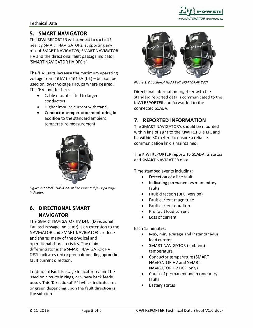
6. DIRECTIONAL SMART NAVIGATOR
The SMART NAVIGATOR HV DFCI (Directional Faulted Passage Indicator) is an extension to the NAVIGATOR and SMART NAVIGATOR products and shares many of the physical and operational characteristics. The main differentiator is the SMART NAVIGATOR HV DFCI indicates red or green depending upon the fault current direction. Traditional Fault Passage Indicators cannot be used on circuits in rings, or where back feeds occur. This ‘Directional’ FPI which indicates red or green depending upon the fault direction is the solution
Figure 8. Directional SMART NAVIGATORHV DFCI.
Directional information together with the standard reported data is communicated to the KIWI REPORTER and forwarded to the connected SCADA.
7. REPORTED INFORMATION The SMART NAVIGATOR’s should be mounted within line of sight to the KIWI REPORTER, and be within 30 meters to ensure a reliable communication link is maintained. The KIWI REPORTER reports to SCADA its status and SMART NAVIGATOR data. Time stamped events including:
Detection of a line fault
Indicating permanent vs momentary faults
Fault direction (DFCI version)
Fault current magnitude
Fault current duration
Pre-fault load current
Loss of current Each 15 minutes:
Max, min, average and instantaneous load current
SMART NAVIGATOR (ambient) temperature
Conductor temperature (SMART NAVIGATOR HV and SMART NAVIGATOR HV DCFI only)
Count of permanent and momentary faults
Battery status

Technical Data
8-11-2016 Page 4 of 7 KIWI REPORTER Technical Data Sheet V1.0.docx
The KIWI REPORTER also reports internal device status such as its battery voltage and the signal strength of connected devices. An additional digital/analogue input allows connection of additional accessories, such as weather stations for wind speed, or door tamper switch detection.
Figure 9. Data can also be automatically transferred via FTP to a server. Above shows Excel graph of line loading and ambient temperature data.
8. The SMART RECIEVER The heart of the KIWI REPORTER is the SMART RECIEVER module which provides low power communications (low power wireless in the word-wide licence-free band of 2.4 GHz ISM band) to the nearby line mounted fault passage indicators (within 30 m line of sight), and the DNP interface (serial or IP) to the radio. A Micro SD card can be fitted in the SMART RECIEVER to provide local data logging of diagnostic data as well as DNP data. This can reduce the number of DNP points to be monitored – simplifying SCADA, but retaining important data for engineering analysis. It can also be used for the logging of line data where communication to SCADA is not yet provided. The memory card can be unplugged and returned to the office for analysis. If Ethernet access is provided, the SMART RECIEVER can automatically upload data on a
daily or weekly interval to your nominated FTP server. Figure 9 provides an example of line load and ambient temperature obtained using this method.
Figure 10. DNP map setup.
The DNP map is configurable, and settings/map can be updated remotely when Ethernet connection is provided.
Figure 11. Setting software provides remote engineering view of status.
Figure 12. Status and history.

Technical Data
8-11-2016 Page 5 of 7 KIWI REPORTER Technical Data Sheet V1.0.docx
Figure 13. Key KIWI REPORTER internal features.
AC surge protection
AC power isolation Battery isolation
Radio antenna surge protection
Battery charger
Customer supplied radio
Low power puck antenna – FPI communication
SMART RECIEVER
Memory card

Technical Data
8-11-2016 Page 6 of 7 KIWI REPORTER Technical Data Sheet V1.0.docx
Figure 14. Key KIWI REPORTER external features.
9. Technical Specifications
KIWI REPORTER KIWI REPORTER SOLAR
External Material Stainless Steel Grade 1.4301 (= AISI 304)
Finish Brushed finish
IP rating IP-65
Temperature -30 to +60 deg C
Weight 30 kg (Battery shipped separately)
55 kg (includes 33 kg of battery which is shipped separately)
Width 356 mm 534 mm
Height 534 mm 712 mm
Depth 200 mm 200 mm
Power supply 90 – 264 Vac 800 mA max
12 V solar 200 W PV cell recommended (1600 x 800 mm, 16 kg)
Battery 12V 33 Ah Absorbent Glass Mat 10 year approx. life
12V 115 Ah Absorbent Glass Mat 10 year approx. life
Option for Lithium battery
Hold up (Aprisa 6W standby and 22.5 W transmit for 1 minute each 15)
24 hours 5.4 days*
Warranty 2 years * Battery capacity allows for multiple cloudy winter days with poor recharge opportunity
Padlockable handle
N Type antenna connection
8 mm earth stud
16 mm & 25 mm gland holes for Aux supply

Technical Data
8-11-2016 Page 7 of 7 KIWI REPORTER Technical Data Sheet V1.0.docx
10. SMART REPORTER Where a high power radio is not required, the SMART REPORTER is offered as an alternative to the KIWI REPORTER.
Figure 15. SMART REPORTER.
Figure 16. SMART REPORTER and low power modem.
Using a very low power GPRS/GSM ‘Raven XE’ modem the SMART REPORTER is the ideal product for sites powered from photo voltaic cells. The low power modem reduces the required size of the solar array and back up battery. These smaller components make installation easier and reduce wind loading. The SMART REPORTER uses a polyester enclosure.
Information is subject to change without notice.
SMART REPORTER & SMART NAVIGATOR are the trademarks of Horstmann GmbH. Aprisa SR+ is the trademark of 4RF Limited. Raven XE is the trademark of Sierra Wireless Inc.