Embed Size (px)
Citation preview
TECHNICAL BULLETININSTALLATION INSTRUCTIONS
FOR SYSTEMS
SINGLE CHANNEL GROUND AND AIRBORNE RADIO SYSTEM (SINCGARS)
AN/VRC-88F, AN/VRC-89F, AN/VRC-90F, AN/VRC-91F, AN/VRC-92F
FORCE XXI BATTLE COMMAND, BRIGADE-AND-BELOW (FBCB2)AN/UYK-128 (V)4
PRECISION LIGHTWEIGHT GPS RECEIVER (PLGR)AN/PSN-11
ENHANCED POSITION LOCATION REPORTING SYSTEM (EPLRS)AN/VSQ-2 (V)
VEHICULAR INTERCOMMUNICATION SET (VIS)AN/VIC-3 (V)20
FOR VEHICLE
TRUCK, UTILITY: UP-ARMORED CARRIER, 4X4, M1114 (2320-01-413-3739) (EIC: B6C).
Approved for public release; distribution is unlimited.
TB 9-2320-387-35-1
HEADQUARTERS, DEPARTMENT OF THE ARMY
OCTOBER 2005

*ARMY TM 9-2320-280-20-1AIR FORCE TO 36A12-1A-2092-1-1
MARINE CORPS TM 2320-20/7B
HEADQUARTERS CHANGE DEPARTMENT OF THE ARMY,NO. 1 Washington, D.C., 1 OCTOBER 2006
TECHNICAL BULLETIN
INSTALLATION INSTRUCTIONS
FOR SYSTEMS
SINGLE CHANNEL GROUND AND AIRBORNE RADIO SYSTEM (SINCGARS)
AN/VRC-88F, AN/VRC-89F, AN/VRC-90F, AN/VRC-91F,AN/VRC-92F
FORCE XXI BATTLE COMMAND, BRIGADE-AND-BELOW (FBCB2)AN/UYK-128 (V)4
PRECISION LIGHTWEIGHT GPS RECEIVER (PLGR)AN/PSN-11
ENHANCED POSITION LOCATION REPORTING SYSTEM (EPLRS)AN/VSQ-2 (V)
VEHICULAR INTERCOMMUNICATION SET (VIS)AN/VIC-3 (V)20
FOR VEHICLE
TRUCK, UTILITY: UP-ARMORED CARRIER, 4X4, M1114 (2320-01-413-3739) (EIC: B6C).
TB 9-2320-387-35-1, 17 October 2005, is changed as follows:1. Remove old pages and insert new pages as indicated below.2. New or changed material is indicated by a vertical bar in the margin of the page.
Remove pages Insert page
A /(B blank) A /(B blank)i through iii/(iv blank) i through iii/(iv blank)4-1 through 4-6 4-1 through 4-65-15 through 5-26 5-15 through 5-265-47 through 5-50 5-47 through 5-505-53 through 5-56 5-53 through 5-56DA Form 2028 DA Form 2028
3. File this change sheet in front of the publication for reference purposes.
Approved for public release; distribution is unlimited.
TB 9-2320-387-35-1

Distribution:
To be distributed in accordance with the Initial Distribution Number (IDN) 344826 requirements for TB 9-2320-387-35-1.
By Order of the Secretary of the Army:
PETER J. SCHOOMAKERGeneral, United States Army
Chief of Staff
Official:
JOYCE E. MORROWAdministrative Assistant to the
Secretary of the Army0620105

TB 9-2320-387-35-1
LIST OF EFFECTIVE PAGES
NNOOTTEEA vertical line in the outer margins of the page indicates theportion of text affected by the change.
Dates of issue for original and change pages are:
Original . . . . . . . . . .0 . . . . . . . 17 October 2005
Change . . . . . . . . . . .1 . . . . . . . . .1 October 2006
TOTAL NUMBER OF PAGES IN THIS PUBLICATION IS 87 PAGES.
Page No. *Change No.A/(B blank) . . . . . . . . . . . . . . . . . . . . . . . . . . . . . . . .1i . . . . . . . . . . . . . . . . . . . . . . . . . . . . . . . . . . . . . . . . .1ii . . . . . . . . . . . . . . . . . . . . . . . . . . . . . . . . . . . . . . . .0iii/(iv blank) . . . . . . . . . . . . . . . . . . . . . . . . . . . . . . .11-1 – 4-1 . . . . . . . . . . . . . . . . . . . . . . . . . . . . . . . . . .04-2–4-6 . . . . . . . . . . . . . . . . . . . . . . . . . . . . . . . . . . .15-1–5-14 . . . . . . . . . . . . . . . . . . . . . . . . . . . . . . . . . .05-15–5-24 . . . . . . . . . . . . . . . . . . . . . . . . . . . . . . . . .15-24.1–5-24.2 Added . . . . . . . . . . . . . . . . . . . . . . . . .15-25 . . . . . . . . . . . . . . . . . . . . . . . . . . . . . . . . . . . . . .15-26–5-47 . . . . . . . . . . . . . . . . . . . . . . . . . . . . . . . . .05-48 . . . . . . . . . . . . . . . . . . . . . . . . . . . . . . . . . . . . . .15-48.1–5-48.4 Added . . . . . . . . . . . . . . . . . . . . . . . . .15-49 . . . . . . . . . . . . . . . . . . . . . . . . . . . . . . . . . . . . . .15-50–5-52 . . . . . . . . . . . . . . . . . . . . . . . . . . . . . . . . .05-53–5-56 . . . . . . . . . . . . . . . . . . . . . . . . . . . . . . . . .1
*Zero in this column indicates original page.
A/(B blank)

i
Approved for public release; distribution is unlimited.
TB 9-2320-387-35-1
TECHNICAL BULLETIN HEADQUARTERS,NO. 9-2320-387-35-1 DEPARTMENT OF THE ARMY
WASHINGTON, D.C., 17 OCTOBER 2005
TECHNICAL BULLETIN INSTALLATION INSTRUCTIONS
FOR SYSTEMS
SINGLE CHANNEL GROUND AND AIRBORNE RADIO SYSTEM (SINCGARS)
AN/VRC-88F, AN/VRC-89F, AN/VRC-90F,AN/VRC-91F, AN/VRC-92F
FORCE XXI BATTLE COMMAND, BRIGADE-AND-BELOW (FBCB2)AN/UYK-128 (V)4
PRECISION LIGHTWEIGHT GPS RECEIVER (PLGR)AN/PSN-11
ENHANCED POSITION LOCATION REPORTING SYSTEM (EPLRS)AN/VSQ-2 (V)
VEHICULAR INTERCOMMUNICATION SET (VIS)AN/VIC-3 (V)20
FOR VEHICLE
TRUCK, UTILITY: UP-ARMORED CARRIER, 4X4, M1114 (2320-01-413-3739) (EIC: B6C).
REPORTING ERRORS AND RECOMMENDING IMPROVEMENTSYou can help improve this publication. If you find any mistakes or if you know of a way to improve the procedures, please let us know. Submit your DA Form 2028(Recommended Changes to Equipment Technical Publications), through the Internet,on the Army Electronic Product Support (AEPS) website. The Internet address ishttps://aeps.ria.army.mil. The DA Form 2028 is located under the Public Applicationssection in the AEPS Public Home Page. Fill out the form and click on SUBMIT. Using thisform on the AEPS will enable us to respond quicker to your comments and better managethe DA Form 2028 program. You may also mail, fax or E-mail your letter or DA Form 2028direct to: AMSTA-LC-LPIT / TECH PUBS, TACOM-RI, 1 Rock Island Arsenal, Rock Island,IL 61299-7630. The email address is [email protected]. The fax numberis DSN 793-0726 or Commercial (309) 782-0726.
Change 1
TB 9-2320-387-35-1
ii
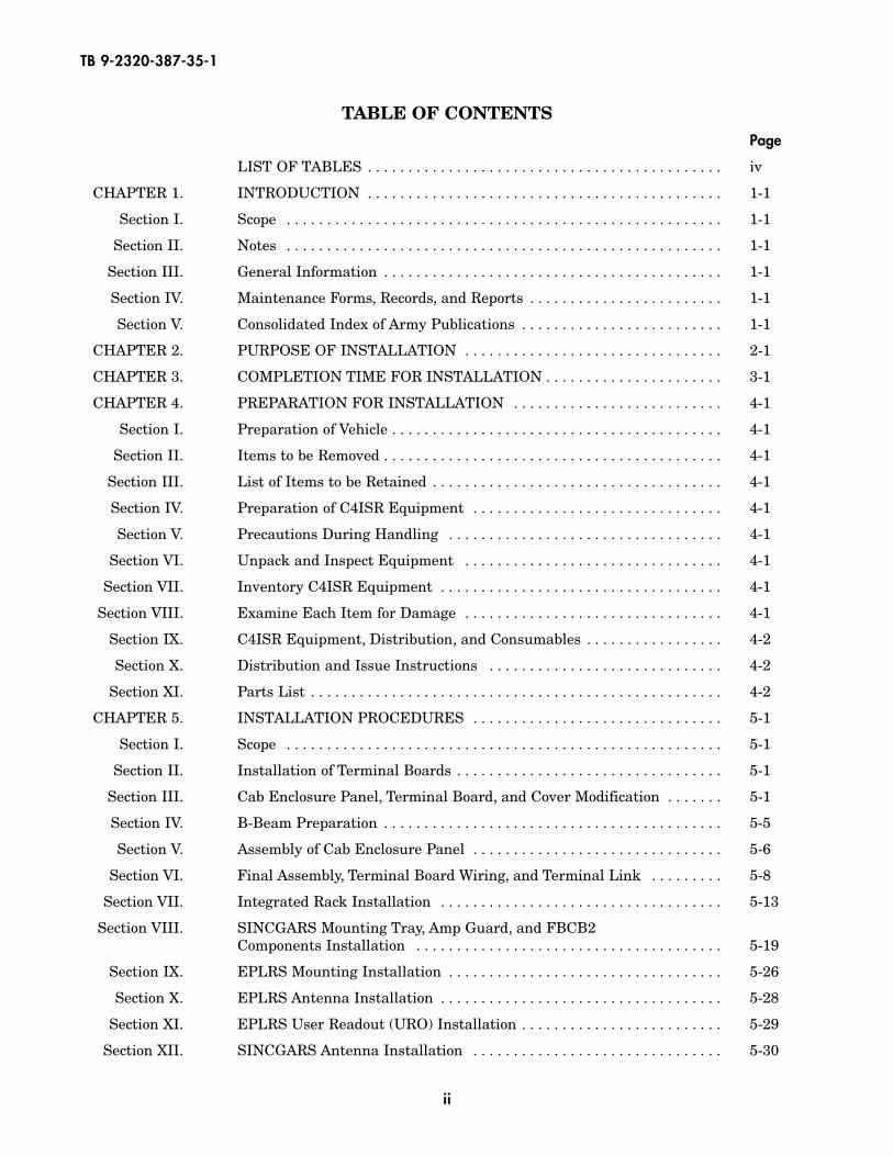
TABLE OF CONTENTSPage
LIST OF TABLES . . . . . . . . . . . . . . . . . . . . . . . . . . . . . . . . . . . . . . . . . . . . iv
CHAPTER 1. INTRODUCTION . . . . . . . . . . . . . . . . . . . . . . . . . . . . . . . . . . . . . . . . . . . . 1-1
Section I. Scope . . . . . . . . . . . . . . . . . . . . . . . . . . . . . . . . . . . . . . . . . . . . . . . . . . . . . . 1-1
Section II. Notes . . . . . . . . . . . . . . . . . . . . . . . . . . . . . . . . . . . . . . . . . . . . . . . . . . . . . . 1-1
Section III. General Information . . . . . . . . . . . . . . . . . . . . . . . . . . . . . . . . . . . . . . . . . . 1-1
Section IV. Maintenance Forms, Records, and Reports . . . . . . . . . . . . . . . . . . . . . . . . 1-1
Section V. Consolidated Index of Army Publications . . . . . . . . . . . . . . . . . . . . . . . . . 1-1
CHAPTER 2. PURPOSE OF INSTALLATION . . . . . . . . . . . . . . . . . . . . . . . . . . . . . . . . 2-1
CHAPTER 3. COMPLETION TIME FOR INSTALLATION . . . . . . . . . . . . . . . . . . . . . . 3-1
CHAPTER 4. PREPARATION FOR INSTALLATION . . . . . . . . . . . . . . . . . . . . . . . . . . 4-1
Section I. Preparation of Vehicle . . . . . . . . . . . . . . . . . . . . . . . . . . . . . . . . . . . . . . . . . 4-1
Section II. Items to be Removed . . . . . . . . . . . . . . . . . . . . . . . . . . . . . . . . . . . . . . . . . . 4-1
Section III. List of Items to be Retained . . . . . . . . . . . . . . . . . . . . . . . . . . . . . . . . . . . . 4-1
Section IV. Preparation of C4ISR Equipment . . . . . . . . . . . . . . . . . . . . . . . . . . . . . . . 4-1
Section V. Precautions During Handling . . . . . . . . . . . . . . . . . . . . . . . . . . . . . . . . . . 4-1
Section VI. Unpack and Inspect Equipment . . . . . . . . . . . . . . . . . . . . . . . . . . . . . . . . 4-1
Section VII. Inventory C4ISR Equipment . . . . . . . . . . . . . . . . . . . . . . . . . . . . . . . . . . . 4-1
Section VIII. Examine Each Item for Damage . . . . . . . . . . . . . . . . . . . . . . . . . . . . . . . . 4-1
Section IX. C4ISR Equipment, Distribution, and Consumables . . . . . . . . . . . . . . . . . 4-2
Section X. Distribution and Issue Instructions . . . . . . . . . . . . . . . . . . . . . . . . . . . . . 4-2
Section XI. Parts List . . . . . . . . . . . . . . . . . . . . . . . . . . . . . . . . . . . . . . . . . . . . . . . . . . . 4-2
CHAPTER 5. INSTALLATION PROCEDURES . . . . . . . . . . . . . . . . . . . . . . . . . . . . . . . 5-1
Section I. Scope . . . . . . . . . . . . . . . . . . . . . . . . . . . . . . . . . . . . . . . . . . . . . . . . . . . . . . 5-1
Section II. Installation of Terminal Boards . . . . . . . . . . . . . . . . . . . . . . . . . . . . . . . . . 5-1
Section III. Cab Enclosure Panel, Terminal Board, and Cover Modification . . . . . . . 5-1
Section IV. B-Beam Preparation . . . . . . . . . . . . . . . . . . . . . . . . . . . . . . . . . . . . . . . . . . 5-5
Section V. Assembly of Cab Enclosure Panel . . . . . . . . . . . . . . . . . . . . . . . . . . . . . . . 5-6
Section VI. Final Assembly, Terminal Board Wiring, and Terminal Link . . . . . . . . . 5-8
Section VII. Integrated Rack Installation . . . . . . . . . . . . . . . . . . . . . . . . . . . . . . . . . . . 5-13
Section VIII. SINCGARS Mounting Tray, Amp Guard, and FBCB2 Components Installation . . . . . . . . . . . . . . . . . . . . . . . . . . . . . . . . . . . . . . 5-19
Section IX. EPLRS Mounting Installation . . . . . . . . . . . . . . . . . . . . . . . . . . . . . . . . . . 5-26
Section X. EPLRS Antenna Installation . . . . . . . . . . . . . . . . . . . . . . . . . . . . . . . . . . . 5-28
Section XI. EPLRS User Readout (URO) Installation . . . . . . . . . . . . . . . . . . . . . . . . . 5-29
Section XII. SINCGARS Antenna Installation . . . . . . . . . . . . . . . . . . . . . . . . . . . . . . . 5-30
TB 9-2320-387-35-1
iii/(iv blank)
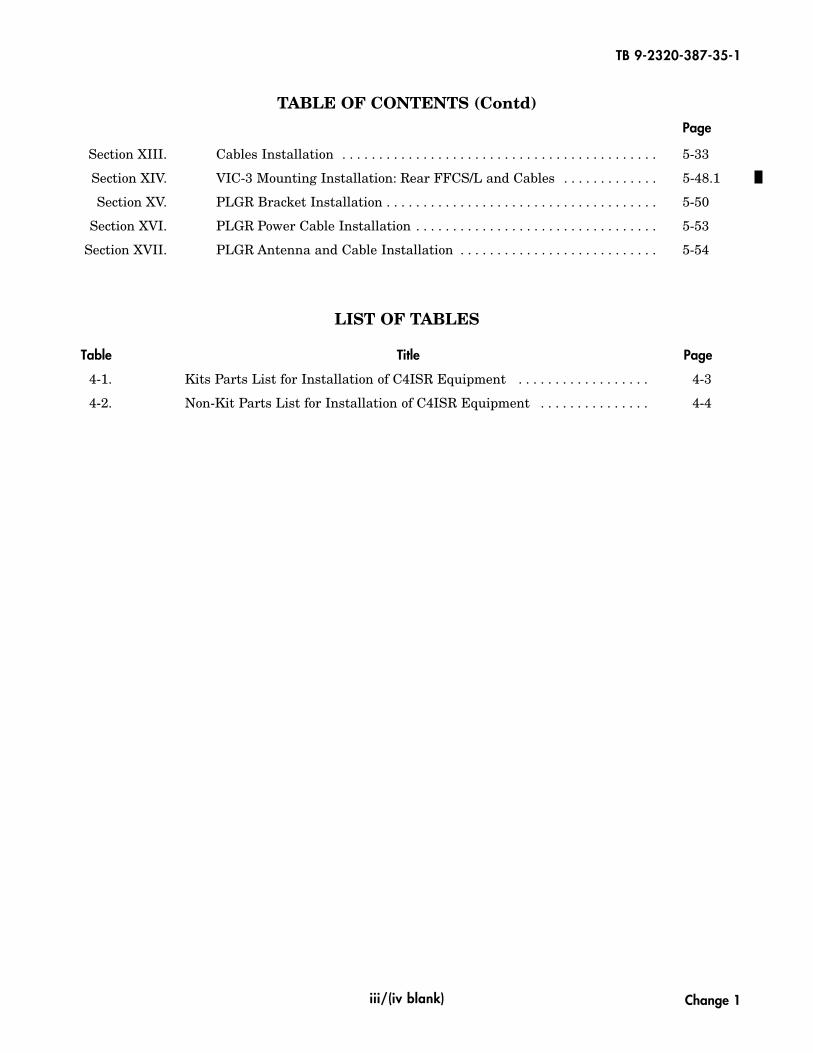
Section XIII. Cables Installation . . . . . . . . . . . . . . . . . . . . . . . . . . . . . . . . . . . . . . . . . . . 5-33
Section XIV. VIC-3 Mounting Installation: Rear FFCS/L and Cables . . . . . . . . . . . . . 5-48.1
Section XV. PLGR Bracket Installation . . . . . . . . . . . . . . . . . . . . . . . . . . . . . . . . . . . . . 5-50
Section XVI. PLGR Power Cable Installation . . . . . . . . . . . . . . . . . . . . . . . . . . . . . . . . . 5-53
Section XVII. PLGR Antenna and Cable Installation . . . . . . . . . . . . . . . . . . . . . . . . . . . 5-54
LIST OF TABLES
Table Title Page
4-1. Kits Parts List for Installation of C4ISR Equipment . . . . . . . . . . . . . . . . . . 4-3
4-2. Non-Kit Parts List for Installation of C4ISR Equipment . . . . . . . . . . . . . . . 4-4
TABLE OF CONTENTS (Contd)Page
Change 1

TB 9-2320-387-35-1
1-1/(1-2 blank)
CHAPTER 1
INTRODUCTION
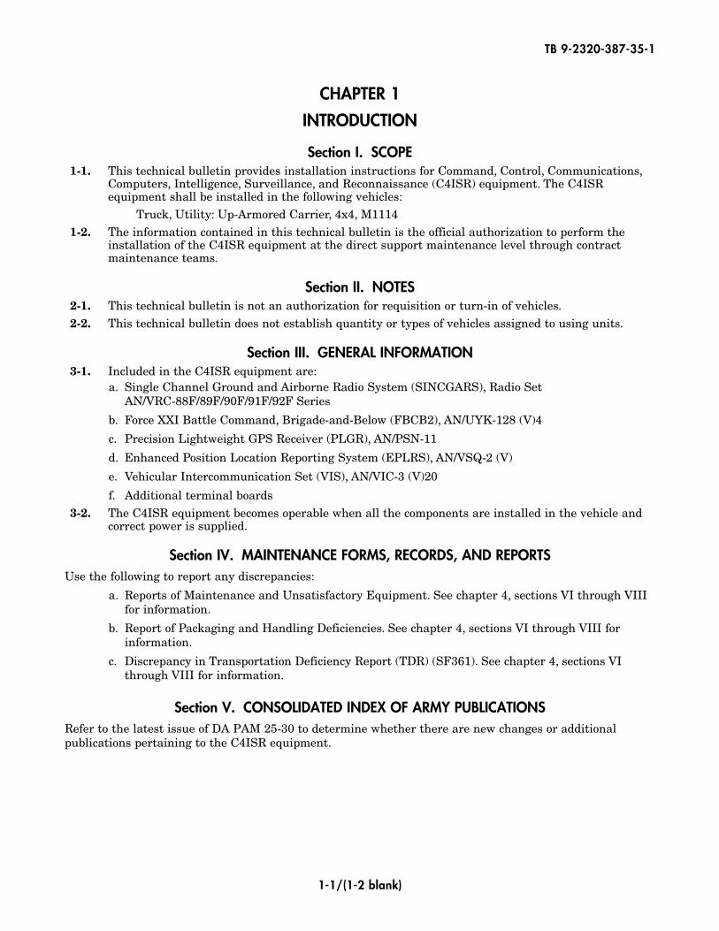
Section I. SCOPE1-1. This technical bulletin provides installation instructions for Command, Control, Communications,
Computers, Intelligence, Surveillance, and Reconnaissance (C4ISR) equipment. The C4ISRequipment shall be installed in the following vehicles:
Truck, Utility: Up-Armored Carrier, 4x4, M11141-2. The information contained in this technical bulletin is the official authorization to perform the
installation of the C4ISR equipment at the direct support maintenance level through contractmaintenance teams.
Section II. NOTES2-1. This technical bulletin is not an authorization for requisition or turn-in of vehicles.2-2. This technical bulletin does not establish quantity or types of vehicles assigned to using units.
Section III. GENERAL INFORMATION3-1. Included in the C4ISR equipment are:
a. Single Channel Ground and Airborne Radio System (SINCGARS), Radio Set AN/VRC-88F/89F/90F/91F/92F Series
b. Force XXI Battle Command, Brigade-and-Below (FBCB2), AN/UYK-128 (V)4
c. Precision Lightweight GPS Receiver (PLGR), AN/PSN-11
d. Enhanced Position Location Reporting System (EPLRS), AN/VSQ-2 (V)
e. Vehicular Intercommunication Set (VIS), AN/VIC-3 (V)20
f. Additional terminal boards3-2. The C4ISR equipment becomes operable when all the components are installed in the vehicle and
correct power is supplied.
Section IV. MAINTENANCE FORMS, RECORDS, AND REPORTSUse the following to report any discrepancies:
a. Reports of Maintenance and Unsatisfactory Equipment. See chapter 4, sections VI through VIIIfor information.
b. Report of Packaging and Handling Deficiencies. See chapter 4, sections VI through VIII forinformation.
c. Discrepancy in Transportation Deficiency Report (TDR) (SF361). See chapter 4, sections VIthrough VIII for information.
Section V. CONSOLIDATED INDEX OF ARMY PUBLICATIONSRefer to the latest issue of DA PAM 25-30 to determine whether there are new changes or additionalpublications pertaining to the C4ISR equipment.


2-1/(2-2 blank)
CHAPTER 2
PURPOSE OF INSTALLATION
The purpose of installing the C4ISR equipment is to provide the primary means of integrating commandand control capability.
TB 9-2320-387-35-1


3-1/(3-2 blank)
CHAPTER 3
COMPLETION TIME FOR INSTALLATION
A total of 20 man hours are required for two personnel to install the C4ISR equipment. Typical vehicledowntime is 12 hours.
TB 9-2320-387-35-1

CHAPTER 4
PREPARATION FOR INSTALLATION
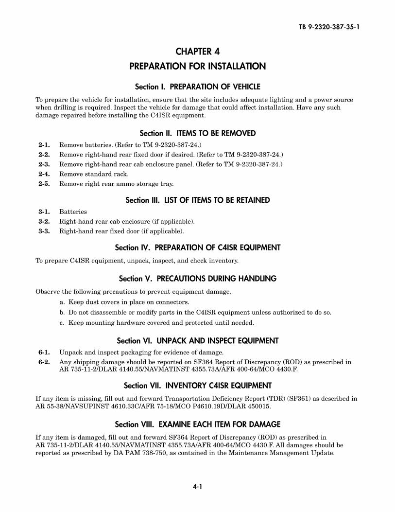
Section I. PREPARATION OF VEHICLE
To prepare the vehicle for installation, ensure that the site includes adequate lighting and a power sourcewhen drilling is required. Inspect the vehicle for damage that could affect installation. Have any suchdamage repaired before installing the C4ISR equipment.
Section II. ITEMS TO BE REMOVED2-1. Remove batteries. (Refer to TM 9-2320-387-24.)2-2. Remove right-hand rear fixed door if desired. (Refer to TM 9-2320-387-24.)2-3. Remove right-hand rear cab enclosure panel. (Refer to TM 9-2320-387-24.)2-4. Remove standard rack.2-5. Remove right rear ammo storage tray.
Section III. LIST OF ITEMS TO BE RETAINED3-1. Batteries3-2. Right-hand rear cab enclosure (if applicable).3-3. Right-hand rear fixed door (if applicable).
Section IV. PREPARATION OF C4ISR EQUIPMENT
To prepare C4ISR equipment, unpack, inspect, and check inventory.
Section V. PRECAUTIONS DURING HANDLING
Observe the following precautions to prevent equipment damage.
a. Keep dust covers in place on connectors.
b. Do not disassemble or modify parts in the C4ISR equipment unless authorized to do so.
c. Keep mounting hardware covered and protected until needed.
Section VI. UNPACK AND INSPECT EQUIPMENT6-1. Unpack and inspect packaging for evidence of damage.6-2. Any shipping damage should be reported on SF364 Report of Discrepancy (ROD) as prescribed in
AR 735-11-2/DLAR 4140.55/NAVMATINST 4355.73A/AFR 400-64/MCO 4430.F.
Section VII. INVENTORY C4ISR EQUIPMENT
If any item is missing, fill out and forward Transportation Deficiency Report (TDR) (SF361) as described inAR 55-38/NAVSUPINST 4610.33C/AFR 75-18/MCO P4610.19D/DLAR 450015.
Section VIII. EXAMINE EACH ITEM FOR DAMAGE
If any item is damaged, fill out and forward SF364 Report of Discrepancy (ROD) as prescribed inAR 735-11-2/DLAR 4140.55/NAVMATINST 4355.73A/AFR 400-64/MCO 4430.F. All damages should bereported as prescribed by DA PAM 738-750, as contained in the Maintenance Management Update.
4-1
TB 9-2320-387-35-1
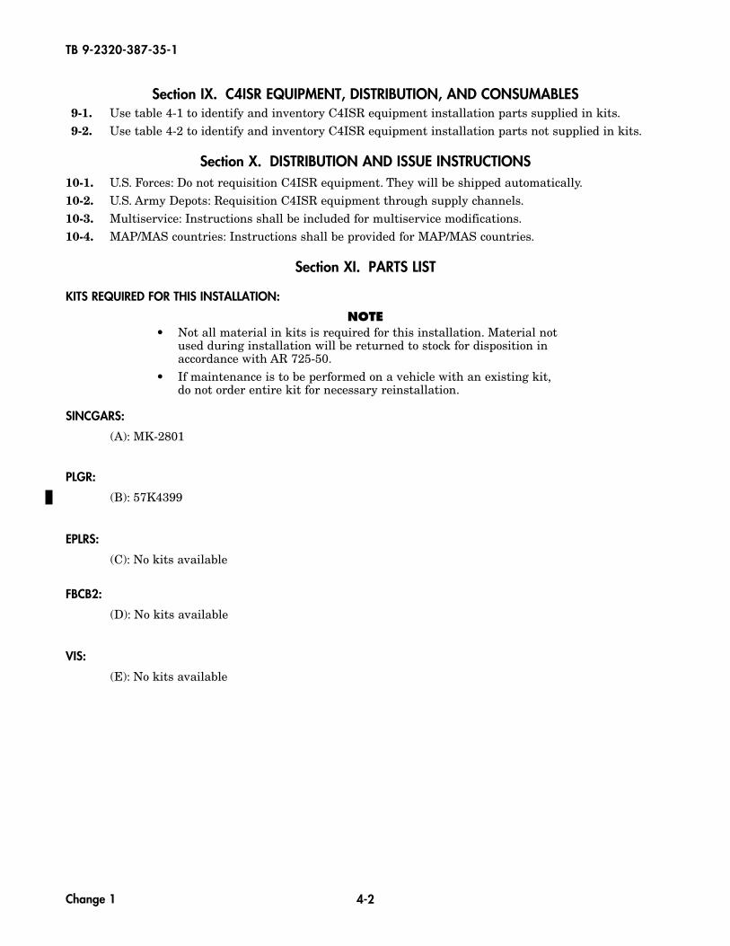
Section IX. C4ISR EQUIPMENT, DISTRIBUTION, AND CONSUMABLES9-1. Use table 4-1 to identify and inventory C4ISR equipment installation parts supplied in kits.9-2. Use table 4-2 to identify and inventory C4ISR equipment installation parts not supplied in kits.
Section X. DISTRIBUTION AND ISSUE INSTRUCTIONS10-1. U.S. Forces: Do not requisition C4ISR equipment. They will be shipped automatically.10-2. U.S. Army Depots: Requisition C4ISR equipment through supply channels.10-3. Multiservice: Instructions shall be included for multiservice modifications.10-4. MAP/MAS countries: Instructions shall be provided for MAP/MAS countries.
Section XI. PARTS LIST
KITS REQUIRED FOR THIS INSTALLATION:
NOTE• Not all material in kits is required for this installation. Material not
used during installation will be returned to stock for disposition inaccordance with AR 725-50.
• If maintenance is to be performed on a vehicle with an existing kit,do not order entire kit for necessary reinstallation.
SINCGARS:
(A): MK-2801
PLGR:
(B): 57K4399
EPLRS:
(C): No kits available
FBCB2:
(D): No kits available
VIS:
(E): No kits available
4-2
TB 9-2320-387-35-1
Change 1
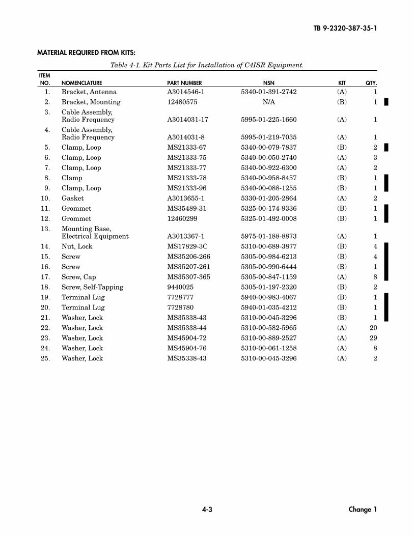
1. Bracket, Antenna A3014546-1 5340-01-391-2742 (A) 12. Bracket, Mounting 12480575 N/A (B) 13. Cable Assembly,
Radio Frequency A3014031-17 5995-01-225-1660 (A) 14. Cable Assembly,
Radio Frequency A3014031-8 5995-01-219-7035 (A) 15. Clamp, Loop MS21333-67 5340-00-079-7837 (B) 26. Clamp, Loop MS21333-75 5340-00-050-2740 (A) 37. Clamp, Loop MS21333-77 5340-00-922-6300 (A) 28. Clamp MS21333-78 5340-00-958-8457 (B) 19. Clamp, Loop MS21333-96 5340-00-088-1255 (B) 1
10. Gasket A3013655-1 5330-01-205-2864 (A) 211. Grommet MS35489-31 5325-00-174-9336 (B) 112. Grommet 12460299 5325-01-492-0008 (B) 113. Mounting Base,
Electrical Equipment A3013367-1 5975-01-188-8873 (A) 114. Nut, Lock MS17829-3C 5310-00-689-3877 (B) 415. Screw MS35206-266 5305-00-984-6213 (B) 416. Screw MS35207-261 5305-00-990-6444 (B) 117. Screw, Cap MS35307-365 5305-00-847-1159 (A) 818. Screw, Self-Tapping 9440025 5305-01-197-2320 (B) 219. Terminal Lug 7728777 5940-00-983-4067 (B) 120. Terminal Lug 7728780 5940-01-035-4212 (B) 121. Washer, Lock MS35338-43 5310-00-045-3296 (B) 122. Washer, Lock MS35338-44 5310-00-582-5965 (A) 2023. Washer, Lock MS45904-72 5310-00-889-2527 (A) 2924. Washer, Lock MS45904-76 5310-00-061-1258 (A) 825. Washer, Lock MS35338-43 5310-00-045-3296 (A) 2
4-3
TB 9-2320-387-35-1
MATERIAL REQUIRED FROM KITS:
Table 4-1. Kit Parts List for Installation of C4ISR Equipment.ITEMNO. NOMENCLATURE PART NUMBER NSN KIT QTY.
Change 1
1. Antenna AS-3900/VRC A3017889-2 5985-01-308-8988 12. Antenna, AS-3499/VSQ-1 A3005031 5820-01-183-9462 13. Antenna, Element (lower) A3018230-1 5985-01-201-1498 14. Antenna, Element (upper) A3017901-2 5985-01-306-4622 15. Antenna, PLGR AT575-030 5985-01-375-4660 16. Assembly, Display Lock 872843-1 N/A 17. Bolt MS35751-18 5306-00-108-9988 48. Box, Stowage 889519-1 2540-01-499-0607 19. Bracket, Mounting 889567-14 N/A 1
10. Bracket, Mounting A3046202 5340-01-237-8102 111. Bracket, Support 12460300 5340-01-456-6554 112. Bracket, PLGR 986-0645-001 5975-01-375-1302 113. Bracket, User Readout (URO) A3006206 5340-01-386-7841 114. Cable Assembly, Antenna, EPLRS SM-C-911480 5995-01-167-1269 115. Cable Assembly, Antenna, PLGR 426-0141-050 6150-01-375-8662 116. Cable Assembly, Ground 12480567-1 N/A 117. Cable Assembly, Power 12480567-2 N/A 118. Cable Assembly, Power, EPLRS A3004939 5995-01-198-0538 119. Cable Assembly, Power, PLGR 9728558-10 6150-01-375-8661 120. Cable Assembly, INC-EPUU A3279383-3 5995-01-453-9171 121. Clamp, Loop MS21333-69 5340-00-764-7051 122. Clamp, Loop MS21333-104 5340-00-088-1254 123. Cable, W1 866003-3 5995-01-478-4908 124. Cable, W2 881327-1 5995-01-478-4876 125. Cable, W3N 881336-1 5995-01-478-4913 126. Cable, W3P 881335-1 5995-01-478-4891 127. Cover, Fuse 1209-9272 N/A 428. CPU (Central Processing Unit) 881292-1 7021-01-474-3793 129. Decal 12339060 7690-01-265-1135 130. Decal 861868-2 N/A 131. Device, Serial Interface Adapter 881331-1 4920-01-478-3722 132. Display 881293-1 7025-01-475-0229 133. Footrest Weldment 889567-21 N/A 134. Grommet, Nonmetallic MS21266-1N 5325-00-960-2410 A/R35. Grommet, Nonmetallic 12338098 5325-01-308-5424 136. Grommet, Nonmetallic 2400 5325-01-289-7859 137. Grommet, Nonmetallic MS35498-149 N/A 138. Guard, Amp 872842-1 5935-01-487-2172 139. Insert 12446871-2 5310-01-411-3422 240. Insert ALS4-616-150 5325-01-483-7480 3
4-4
TB 9-2320-387-35-1
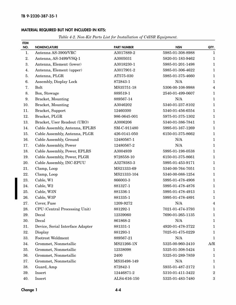
MATERIAL REQUIRED BUT NOT INCLUDED IN KITS:
Table 4-2. Non-Kit Parts List for Installation of C4ISR Equipment.ITEMNO. NOMENCLATURE PART NUMBER NSN QTY.
Change 1
41. Insert 12446871-11 5325-01-505-3122 142. Insert 12446871-1 5310-01-413-3276 443. Interface Unit, FFCS A3206624 5895-01-469-6120 244. Isolation Kit, CPU 872826-2 5340-01-481-5741 145. Isolation Kit, Display 872870-1 5340-01-481-5757 146. Lanyard 8925T5-7X19 4010-01-497-2675 147. Left Rail Weldment 889567-12 N/A 148. Master Control Station A3206623 5895-01-469-3352 149. Mount, Ramball RAM-D-111U 5975-01-485-3615 150. Mount, Resilient MT-6146/VSQ-1 5340-01-167-8297 151. Nut MS35649-2252 5310-00-997-1888 452. Nut 13218E0320-293 5310-00-913-8881 453. Nut 9418931 5310-01-187-7610 454. Nut 9418892 5310-01-157-9819 755. Nut 9417954 5310-00-931-8167 756. Nut MS35649-63 5310-00-804-3859 557. Nut 271169 5310-00-124-9265 558. Nut, Lock 271175 5310-01-333-5245 659. Nut, Lock MS51943-31 460. Panel, Enclosure 12447141 2510-01-413-5993 161. Right Rail Weldment 889567-22 N/A 162. Rivet, Blind 12339355-1 5320-01-271-6357 263. Rod 889567-16 N/A 164. Screw, Cap B1821BH025C075N 5305-00-068-0508 265. Screw, Cap B1821BH031F100N 5305-00-051-4076 266. Screw, Cap B1821BH031F125N 5305-00-051-4078 667. Screw, Cap B1821AH025C150N 368. Screw, Cap B1821AH025C100N 5305-01-389-7984 669. Screw, Cap B1821AH025C063N 5305-01-457-8854 170. Screw, Cap B1821BH025C088N 5305-00-071-2505 671. Screw, Cap B1821BH031C075N 472. Screw, Cap B1821BH031C100N 5306-00-226-4827 473. Screw, Cap B1821BH031C150N 274. Screw, Cap B1821AH025C075N 5305-01-389-8000 375. Screw, Machine MS35206-230 5305-00-889-3000 576. Screw, Machine MS35190-287 5305-00-954-4295 277. Screw, Machine MS35190-291 5305-00-958-5247 278. Screw, Machine MS35207-263 5305-00-989-7434 279. Screw, Self-Tapping 9421073 5305-01-162-8512 580. Screw, Self-Tapping 9426635 N/A 4
4-5
TB 9-2320-387-35-1
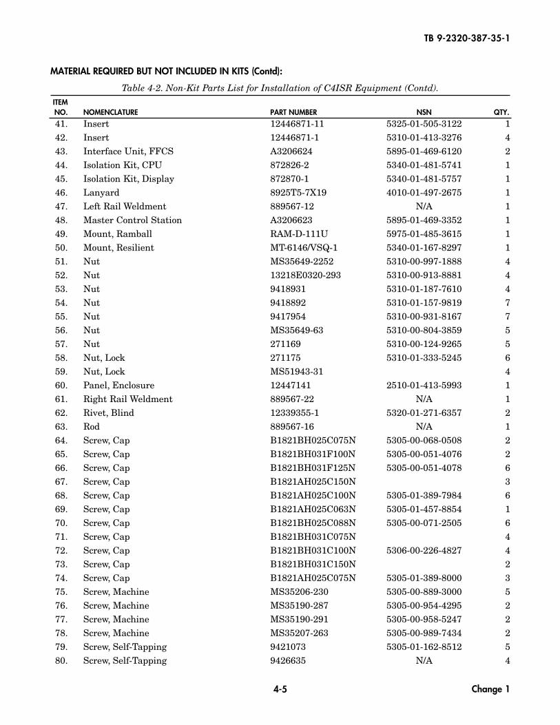
MATERIAL REQUIRED BUT NOT INCLUDED IN KITS (Contd):
Table 4-2. Non-Kit Parts List for Installation of C4ISR Equipment (Contd).ITEMNO. NOMENCLATURE PART NUMBER NSN QTY.
Change 1
81. Screw, Self-Tapping 12342499-2 5305-01-264-5809 1182. Spacer 92510A318 N/A 483. Spacer 10705AL315C 5365-01-487-3145 484. Spacer 5579297 5365-01-194-0761 385. Strap, Tiedown MS3367-1-0 5975-00-984-6582 286. Support Rack 889509-22 N/A 187. Terminal Board 12480570 N/A 188. Terminal Board MS27212-3-8 5940-00-950-7782 189. Terminal Board Cover 12480569-1 N/A 190. Terminal Board Cover 12480569-2 N/A 191. Terminal Board Cover MS18029-3S-2 5940-01-280-9304 292. Terminal Link MS25266-6N-2 6150-01-167-9267 193. Terminal Lug MS20659-108 5940-00-115-2674 194. Terminal Lug MS20659-141 5940-00-113-9825 495. Tubing, Shrink MS23053/4-302-0 5970-01-161-6796 A/R96. Washer 12338095 5310-01-208-7576 397. Washer MS51412-23 5310-01-333-0060 298. Washer MS27183-10 5310-00-809-4058 1099. Washer 2436161 5310-01-102-3270 9
100. Washer MS27183-47 5310-01-312-4959 2101. Washer 2436162 5310-01-119-1024 8102. Washer 2436164 5310-01-278-9555 6103. Washer, Lock MS35338-45 5310-00-407-9566 6104. Washer, Lock MS35338-48 5310-00-584-5272 3105. Washer, Lock MS35338-41 5310-00-045-4007 5106. Wingnut MS51553-420 5310-01-384-2546 4107. Wire Assembly, Fuse (12V) 12480568-2 N/A 1108. Wire Assembly, Fuse (24V) 12480568-1 N/A 3109. Wire, Braided AA59569F30T0375 6145-00-191-8402 A/R110. Wire, Lock MS20995C32 9505-00-293-4208 A/R
4-6
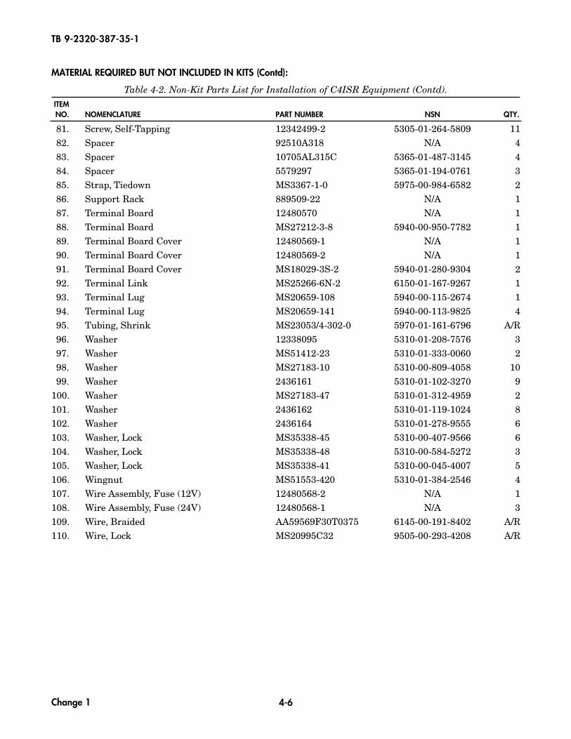
TB 9-2320-387-35-1
MATERIAL REQUIRED BUT NOT INCLUDED IN KITS (Contd):
Table 4-2. Non-Kit Parts List for Installation of C4ISR Equipment (Contd).ITEMNO. NOMENCLATURE PART NUMBER NSN QTY.
Change 1
CHAPTER 5INSTALLATION PROCEDURES
Section I. SCOPEThis chapter provides instructions for installation of the following C4ISR equipment:
• Single Channel Ground and Airborne Radio System (SINCGARS)• Precision Lightweight Global Positioning System Receiver (PLGR)• Enhanced Position Location Reporting System (EPLRS)• Vehicular Intercommunications Set (VIS)• Force XXI Battle Command, Brigade-and-Below (FBCB2)• Additional terminal boards in the vehicle
Perform the steps in this chapter when installing SINCGARS, PLGR, EPLRS, VIS, FBCB2, and additionalterminal boards. When installing C4ISR equipment, be sure to read and follow instructions andillustrations carefully.
Section II. INSTALLATION OF TERMINAL BOARDSUse the following procedure to install additional terminal boards to provide adequate power connections.Vehicles must have dual-voltage alternators installed in order to have both 12V and 24V terminal boardsinstalled.
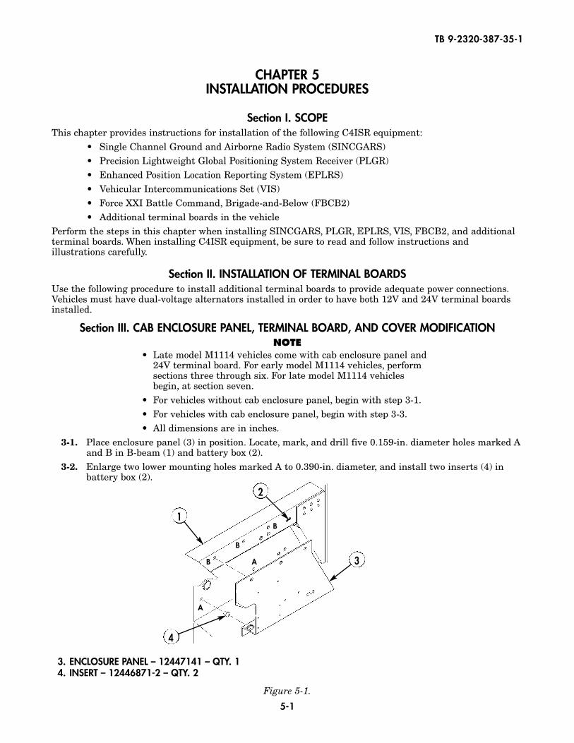
Section III. CAB ENCLOSURE PANEL, TERMINAL BOARD, AND COVER MODIFICATIONNOTE
• Late model M1114 vehicles come with cab enclosure panel and 24V terminal board. For early model M1114 vehicles, perform sections three through six. For late model M1114 vehicles begin, at section seven.
• For vehicles without cab enclosure panel, begin with step 3-1.• For vehicles with cab enclosure panel, begin with step 3-3.• All dimensions are in inches.
3-1. Place enclosure panel (3) in position. Locate, mark, and drill five 0.159-in. diameter holes marked Aand B in B-beam (1) and battery box (2).
3-2. Enlarge two lower mounting holes marked A to 0.390-in. diameter, and install two inserts (4) inbattery box (2).
5-1
TB 9-2320-387-35-1
Figure 5-1.
3. ENCLOSURE PANEL – 12447141 – QTY. 14. INSERT – 12446871-2 – QTY. 2
1
2
3
4
~
A
AB
B
B
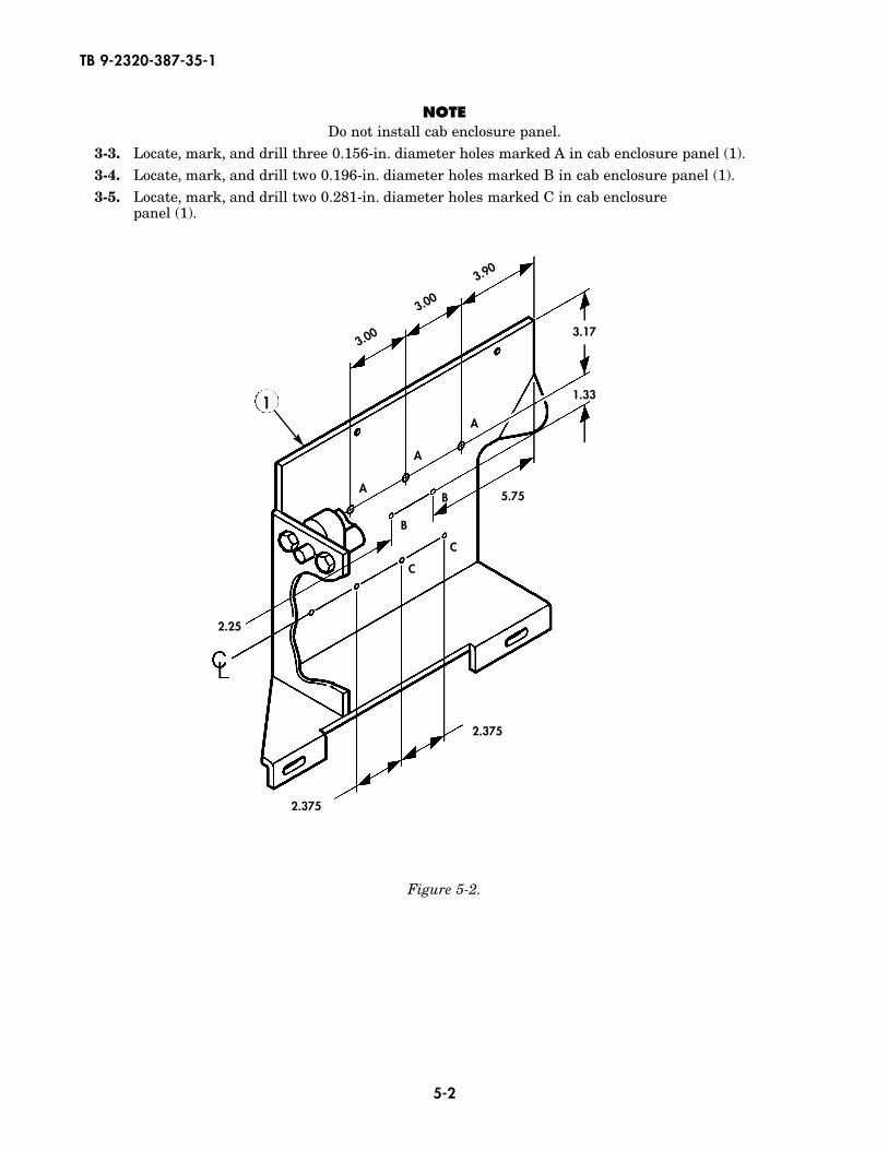
NOTEDo not install cab enclosure panel.
3-3. Locate, mark, and drill three 0.156-in. diameter holes marked A in cab enclosure panel (1).3-4. Locate, mark, and drill two 0.196-in. diameter holes marked B in cab enclosure panel (1).3-5. Locate, mark, and drill two 0.281-in. diameter holes marked C in cab enclosure
panel (1).
5-2
TB 9-2320-387-35-1
3.17
1.33
5.75
2.25
2.375
2.375
3.00
3.00
3.90
C
C
A
A
A
B
B
1
Figure 5-2.
5-3
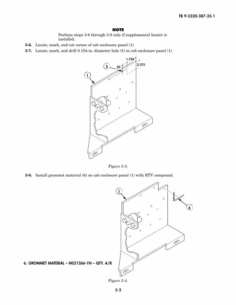
NOTEPerform steps 3-6 through 3-8 only if supplemental heater isinstalled.
3-6. Locate, mark, and cut corner of cab enclosure panel (1).3-7. Locate, mark, and drill 0.154-in. diameter hole (5) in cab enclosure panel (1).
3-8. Install grommet material (6) on cab enclosure panel (1) with RTV compound.
TB 9-2320-387-35-1
1
1
6
5
Figure 5-3.
Figure 5-4.
.502.375
1.750
6. GROMMET MATERIAL – MS21266-1N – QTY. A/R
5-4
TB 9-2320-387-35-1
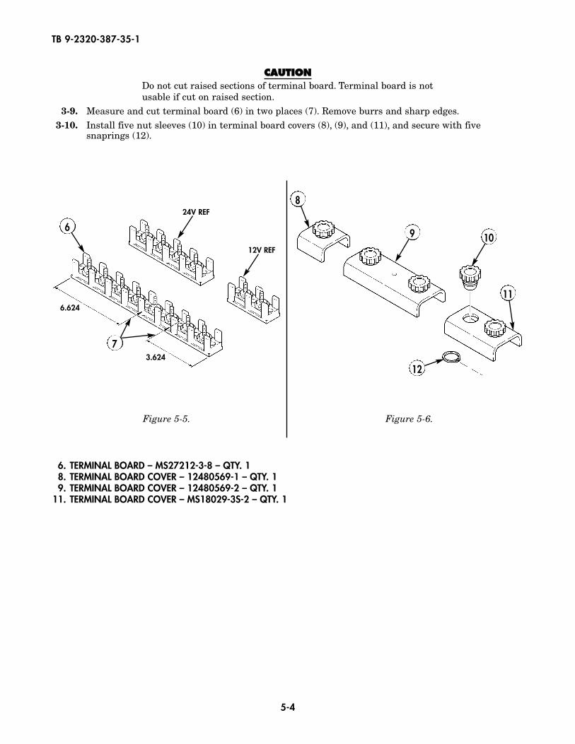
CCAAUUTTIIOONNDo not cut raised sections of terminal board. Terminal board is notusable if cut on raised section.
3-9. Measure and cut terminal board (6) in two places (7). Remove burrs and sharp edges.3-10. Install five nut sleeves (10) in terminal board covers (8), (9), and (11), and secure with five
snaprings (12).
Figure 5-5. Figure 5-6.
6.624
24V REF
3.624
6
7
8
9 10
12
11
12V REF
6. TERMINAL BOARD – MS27212-3-8 – QTY. 18. TERMINAL BOARD COVER – 12480569-1 – QTY. 19. TERMINAL BOARD COVER – 12480569-2 – QTY. 1
11. TERMINAL BOARD COVER – MS18029-3S-2 – QTY. 1
5-5
TB 9-2320-387-35-1
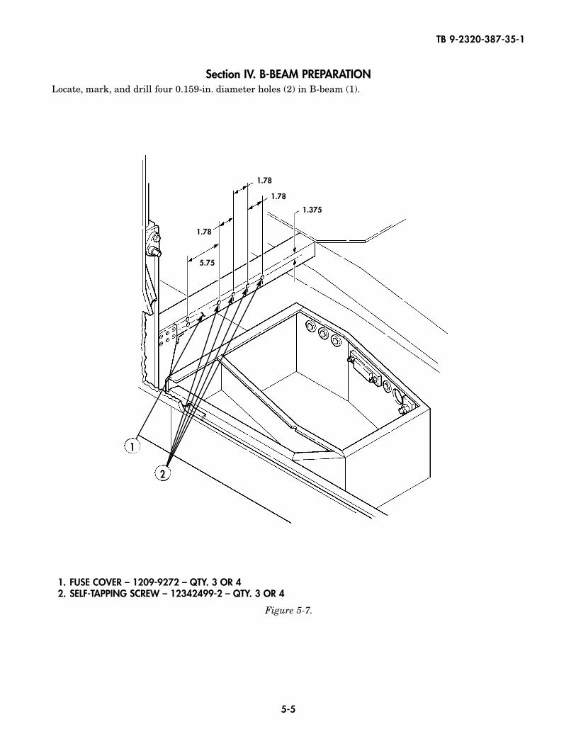
Section IV. B-BEAM PREPARATIONLocate, mark, and drill four 0.159-in. diameter holes (2) in B-beam (1).
Figure 5-7.
1. FUSE COVER – 1209-9272 – QTY. 3 OR 42. SELF-TAPPING SCREW – 12342499-2 – QTY. 3 OR 4
1
1.78
5.75
1.78
1.78
1.375
~
2
5-6
TB 9-2320-387-35-1
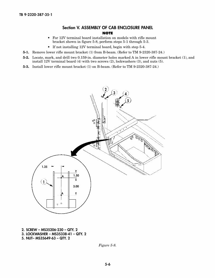
Section V. ASSEMBLY OF CAB ENCLOSURE PANELNOTE
• For 12V terminal board installation on models with rifle mountbracket shown in figure 5-8, perform steps 5-1 through 5-3.
• If not installing 12V terminal board, begin with step 5-4.5-1. Remove lower rifle mount bracket (1) from B-beam. (Refer to TM 9-2320-387-24.)5-2. Locate, mark, and drill two 0.159-in. diameter holes marked A in lower rifle mount bracket (1), and
install 12V terminal board (4) with two screws (2), lockwashers (3), and nuts (5).5-3. Install lower rifle mount bracket (1) on B-beam. (Refer to TM 9-2320-387-24.)
Figure 5-8.
3 4
5
1
2
1.35
1.50
3.00
A
A
2. SCREW – MS35206-230 – QTY. 23. LOCKWASHER – MS35338-41 – QTY. 25. NUT– MS35649-63 – QTY. 2
5-7
TB 9-2320-387-35-1
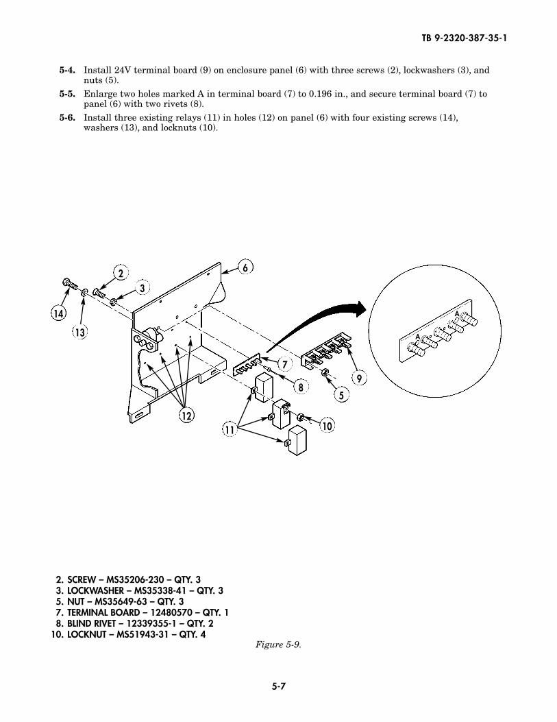
5-4. Install 24V terminal board (9) on enclosure panel (6) with three screws (2), lockwashers (3), andnuts (5).
5-5. Enlarge two holes marked A in terminal board (7) to 0.196 in., and secure terminal board (7) to panel (6) with two rivets (8).
5-6. Install three existing relays (11) in holes (12) on panel (6) with four existing screws (14),washers (13), and locknuts (10).
Figure 5-9.
A
A
32 6
97
85
10
13
1211
14
2. SCREW – MS35206-230 – QTY. 33. LOCKWASHER – MS35338-41 – QTY. 35. NUT – MS35649-63 – QTY. 37. TERMINAL BOARD – 12480570 – QTY. 18. BLIND RIVET – 12339355-1 – QTY. 2
10. LOCKNUT – MS51943-31 – QTY. 4
5-8
TB 9-2320-387-35-1
Figure 5-11.
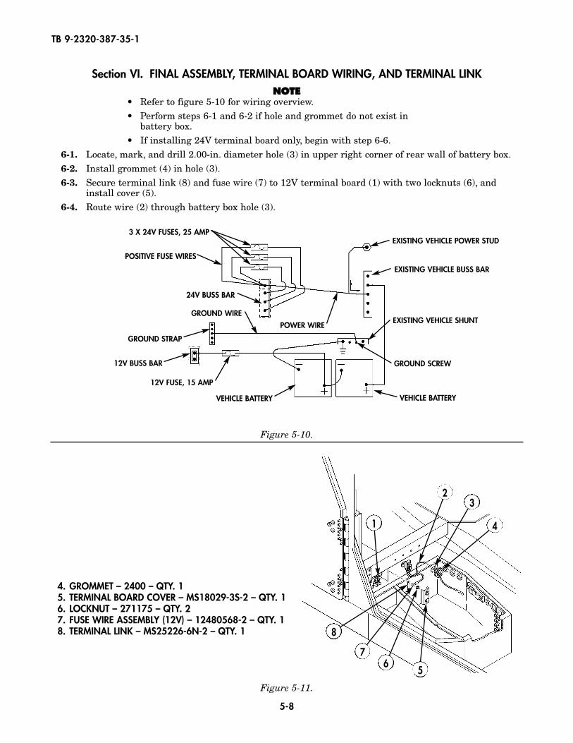
Section VI. FINAL ASSEMBLY, TERMINAL BOARD WIRING, AND TERMINAL LINKNNOOTTEE
• Refer to figure 5-10 for wiring overview.• Perform steps 6-1 and 6-2 if hole and grommet do not exist in
battery box.• If installing 24V terminal board only, begin with step 6-6.
6-1. Locate, mark, and drill 2.00-in. diameter hole (3) in upper right corner of rear wall of battery box.6-2. Install grommet (4) in hole (3).6-3. Secure terminal link (8) and fuse wire (7) to 12V terminal board (1) with two locknuts (6), and
install cover (5).6-4. Route wire (2) through battery box hole (3).
Figure 5-10.
3 X 24V FUSES, 25 AMP
POSITIVE FUSE WIRES
24V BUSS BAR
GROUND WIRE
VEHICLE BATTERY
12V FUSE, 15 AMP
12V BUSS BAR
GROUND STRAP
POWER WIRE
EXISTING VEHICLE POWER STUD
EXISTING VEHICLE BUSS BAR
EXISTING VEHICLE SHUNT
GROUND SCREW
VEHICLE BATTERY
4. GROMMET – 2400 – QTY. 15. TERMINAL BOARD COVER – MS18029-3S-2 – QTY. 16. LOCKNUT – 271175 – QTY. 27. FUSE WIRE ASSEMBLY (12V) – 12480568-2 – QTY. 18. TERMINAL LINK – MS25226-6N-2 – QTY. 1
1
23
5
4
67
8
5-9
TB 9-2320-387-35-1
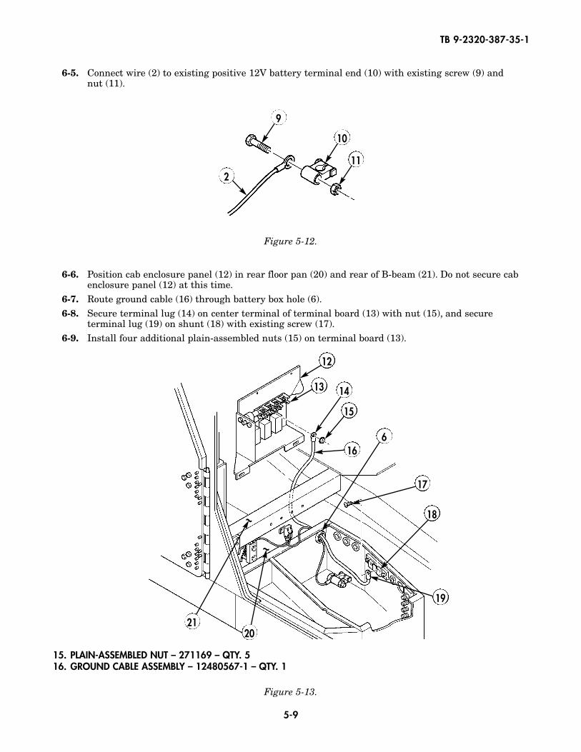
6-5. Connect wire (2) to existing positive 12V battery terminal end (10) with existing screw (9) and nut (11).
6-6. Position cab enclosure panel (12) in rear floor pan (20) and rear of B-beam (21). Do not secure cabenclosure panel (12) at this time.
6-7. Route ground cable (16) through battery box hole (6).6-8. Secure terminal lug (14) on center terminal of terminal board (13) with nut (15), and secure
terminal lug (19) on shunt (18) with existing screw (17).6-9. Install four additional plain-assembled nuts (15) on terminal board (13).
Figure 5-12.
Figure 5-13.
12
9
10
112
13
16
14
17
6
18
19
2120
15
~
~
15. PLAIN-ASSEMBLED NUT – 271169 – QTY. 516. GROUND CABLE ASSEMBLY – 12480567-1 – QTY. 1
5-10
TB 9-2320-387-35-1
Figure 5-14.
26
6
23
22
22
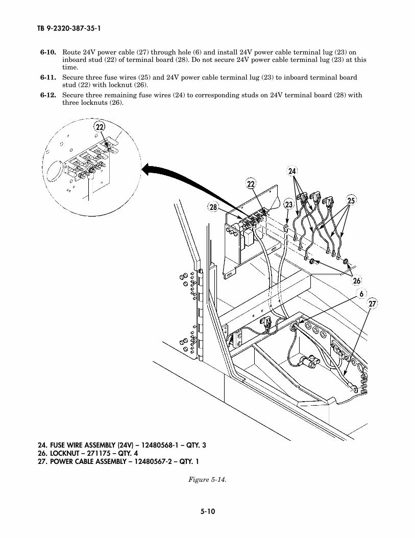
6-10. Route 24V power cable (27) through hole (6) and install 24V power cable terminal lug (23) oninboard stud (22) of terminal board (28). Do not secure 24V power cable terminal lug (23) at thistime.
6-11. Secure three fuse wires (25) and 24V power cable terminal lug (23) to inboard terminal board stud (22) with locknut (26).
6-12. Secure three remaining fuse wires (24) to corresponding studs on 24V terminal board (28) withthree locknuts (26).
24. FUSE WIRE ASSEMBLY (24V) – 12480568-1 – QTY. 326. LOCKNUT – 271175 – QTY. 427. POWER CABLE ASSEMBLY – 12480567-2 – QTY. 1
25
27
24
28
5-11
TB 9-2320-387-35-1
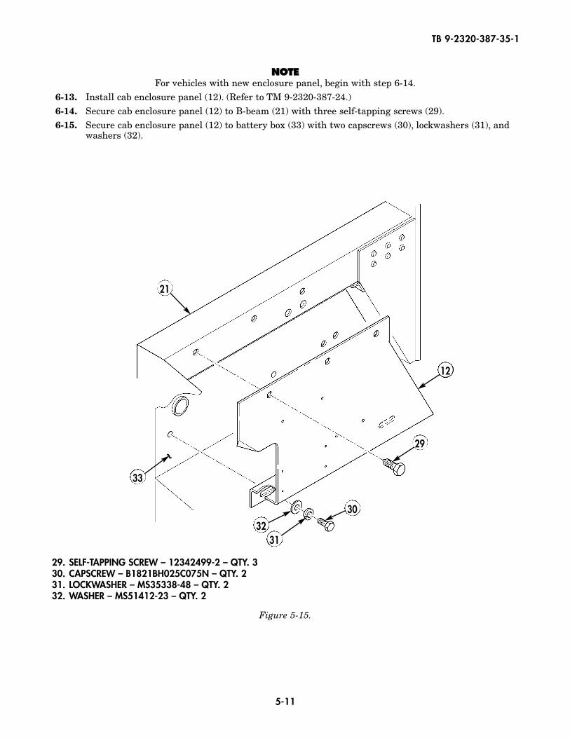
NNOOTTEEFor vehicles with new enclosure panel, begin with step 6-14.
6-13. Install cab enclosure panel (12). (Refer to TM 9-2320-387-24.)6-14. Secure cab enclosure panel (12) to B-beam (21) with three self-tapping screws (29).6-15. Secure cab enclosure panel (12) to battery box (33) with two capscrews (30), lockwashers (31), and
washers (32).
Figure 5-15.
12
29
30
3231
33
21
~
29. SELF-TAPPING SCREW – 12342499-2 – QTY. 330. CAPSCREW – B1821BH025C075N – QTY. 231. LOCKWASHER – MS35338-48 – QTY. 232. WASHER – MS51412-23 – QTY. 2
5-12
TB 9-2320-387-35-1
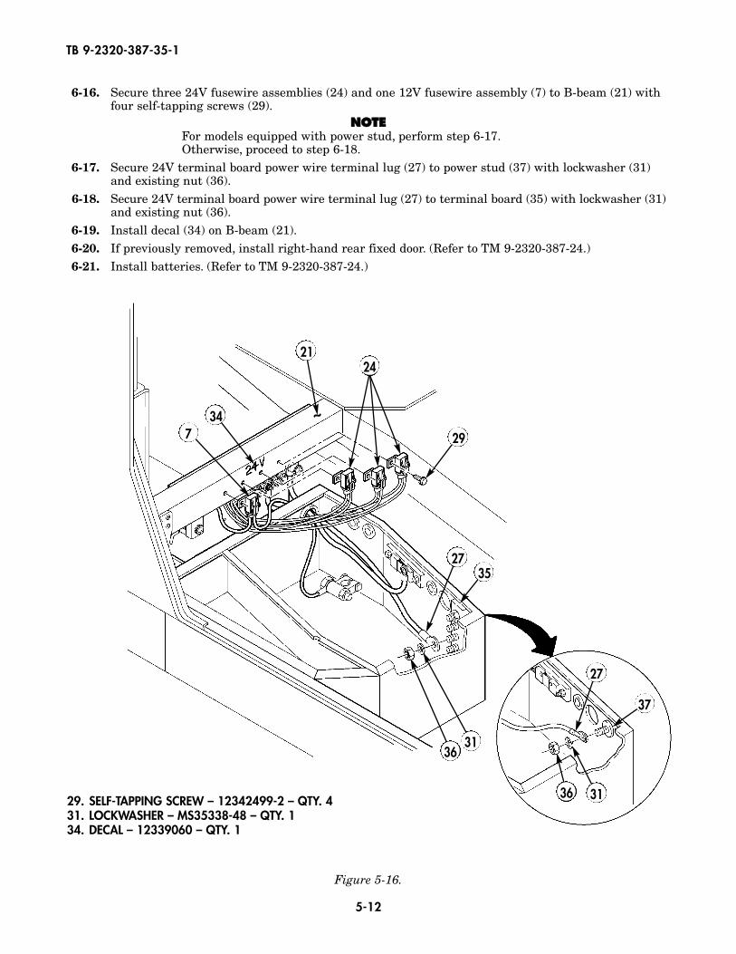
6-16. Secure three 24V fusewire assemblies (24) and one 12V fusewire assembly (7) to B-beam (21) withfour self-tapping screws (29).
NNOOTTEEFor models equipped with power stud, perform step 6-17.Otherwise, proceed to step 6-18.
6-17. Secure 24V terminal board power wire terminal lug (27) to power stud (37) with lockwasher (31)and existing nut (36).
6-18. Secure 24V terminal board power wire terminal lug (27) to terminal board (35) with lockwasher (31)and existing nut (36).
6-19. Install decal (34) on B-beam (21).6-20. If previously removed, install right-hand rear fixed door. (Refer to TM 9-2320-387-24.)6-21. Install batteries. (Refer to TM 9-2320-387-24.)
Figure 5-16.
34
21
29
2735
3136
7
27
37
313629. SELF-TAPPING SCREW – 12342499-2 – QTY. 431. LOCKWASHER – MS35338-48 – QTY. 134. DECAL – 12339060 – QTY. 1
24
~
5-13
TB 9-2320-387-35-1
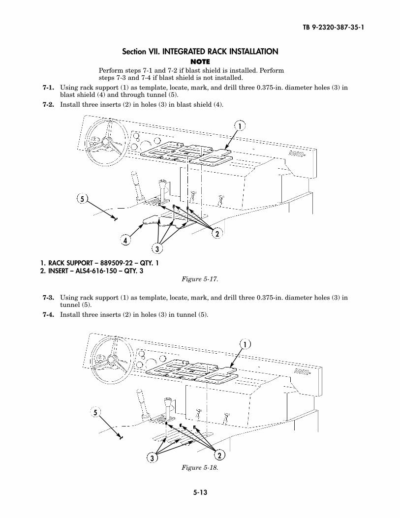
Section VII. INTEGRATED RACK INSTALLATIONNOTE
Perform steps 7-1 and 7-2 if blast shield is installed. Performsteps 7-3 and 7-4 if blast shield is not installed.
7-1. Using rack support (1) as template, locate, mark, and drill three 0.375-in. diameter holes (3) inblast shield (4) and through tunnel (5).
7-2. Install three inserts (2) in holes (3) in blast shield (4).
7-3. Using rack support (1) as template, locate, mark, and drill three 0.375-in. diameter holes (3) intunnel (5).
7-4. Install three inserts (2) in holes (3) in tunnel (5).
1. RACK SUPPORT – 889509-22 – QTY. 12. INSERT – ALS4-616-150 – QTY. 3
Figure 5-17.
Figure 5-18.
1
24
5
3
~
~
1
23
5
5-14
TB 9-2320-387-35-1
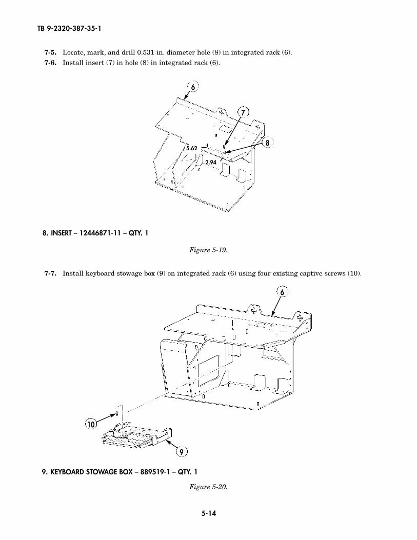
7-7. Install keyboard stowage box (9) on integrated rack (6) using four existing captive screws (10).
Figure 5-20.
6
10
9
Figure 5-19.
7
6
8. INSERT – 12446871-11 – QTY. 1
9. KEYBOARD STOWAGE BOX – 889519-1 – QTY. 1
8
2.94
5.62
7-5. Locate, mark, and drill 0.531-in. diameter hole (8) in integrated rack (6).7-6. Install insert (7) in hole (8) in integrated rack (6).
5-15
TB 9-2320-387-35-1
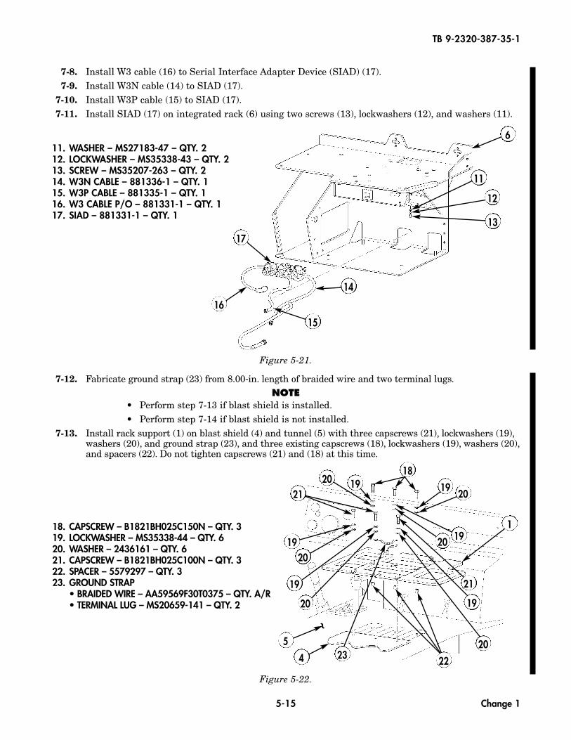
18. CAPSCREW – B1821BH025C150N – QTY. 319. LOCKWASHER – MS35338-44 – QTY. 620. WASHER – 2436161 – QTY. 621. CAPSCREW – B1821BH025C100N – QTY. 322. SPACER – 5579297 – QTY. 323. GROUND STRAP
• BRAIDED WIRE – AA59569F30T0375 – QTY. A/R• TERMINAL LUG – MS20659-141 – QTY. 2
7-8. Install W3 cable (16) to Serial Interface Adapter Device (SIAD) (17).7-9. Install W3N cable (14) to SIAD (17).
7-10. Install W3P cable (15) to SIAD (17).7-11. Install SIAD (17) on integrated rack (6) using two screws (13), lockwashers (12), and washers (11).
Figure 5-21.
7-12. Fabricate ground strap (23) from 8.00-in. length of braided wire and two terminal lugs.NOTE
• Perform step 7-13 if blast shield is installed.• Perform step 7-14 if blast shield is not installed.
7-13. Install rack support (1) on blast shield (4) and tunnel (5) with three capscrews (21), lockwashers (19),washers (20), and ground strap (23), and three existing capscrews (18), lockwashers (19), washers (20),and spacers (22). Do not tighten capscrews (21) and (18) at this time.
12
11
13
14
15
16
11. WASHER – MS27183-47 – QTY. 212. LOCKWASHER – MS35338-43 – QTY. 213. SCREW – MS35207-263 – QTY. 214. W3N CABLE – 881336-1 – QTY. 115. W3P CABLE – 881335-1 – QTY. 116. W3 CABLE P/O – 881331-1 – QTY. 117. SIAD – 881331-1 – QTY. 1
Figure 5-22.
2020
20
1
23
1919
19
4
5
20
20
21
19
20
19
19
~
6
18
21
22
17
Change 1
5-16
TB 9-2320-387-35-1
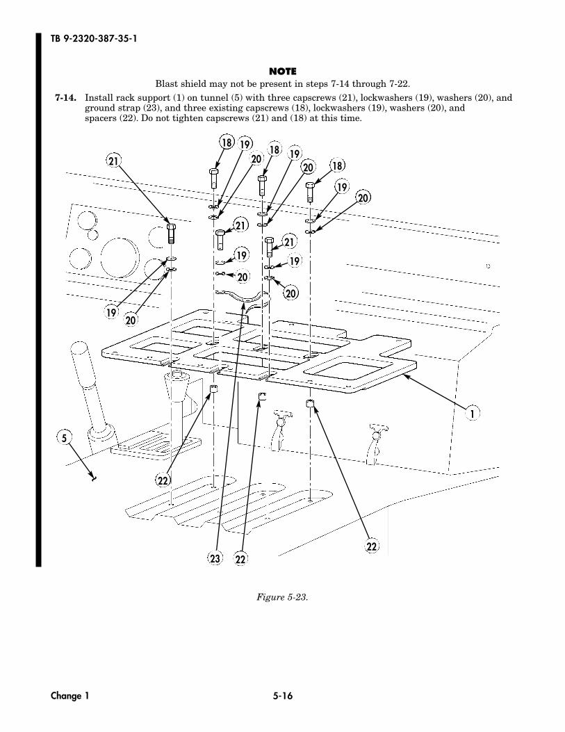
NOTEBlast shield may not be present in steps 7-14 through 7-22.
7-14. Install rack support (1) on tunnel (5) with three capscrews (21), lockwashers (19), washers (20), andground strap (23), and three existing capscrews (18), lockwashers (19), washers (20), andspacers (22). Do not tighten capscrews (21) and (18) at this time.
Figure 5-23.
2222
22
23
2019
18201918
201918
5
1
21
2019
19
21
2019
21
20
~
Change 1
5-17
TB 9-2320-387-35-1
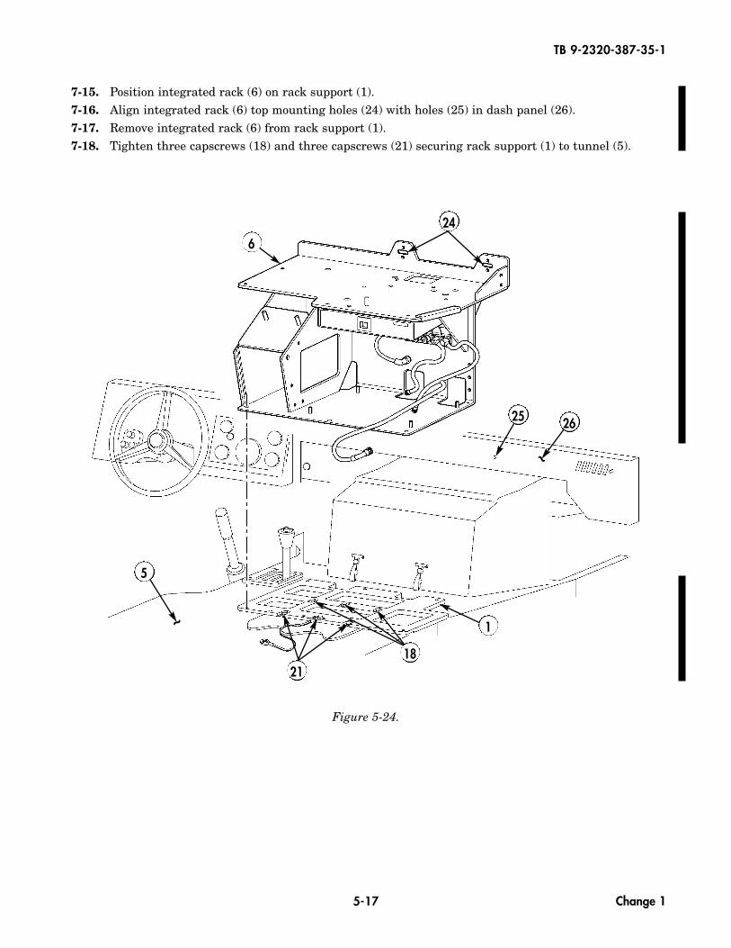
7-15. Position integrated rack (6) on rack support (1).7-16. Align integrated rack (6) top mounting holes (24) with holes (25) in dash panel (26).7-17. Remove integrated rack (6) from rack support (1).7-18. Tighten three capscrews (18) and three capscrews (21) securing rack support (1) to tunnel (5).
Figure 5-24.
6
26
5
25
1
1821
24
~
~
Change 1
5-18
TB 9-2320-387-35-1
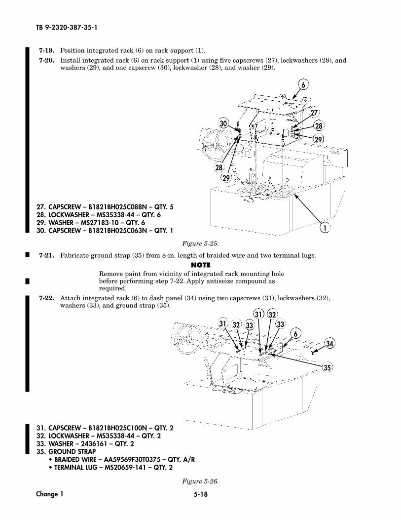
7-19. Position integrated rack (6) on rack support (1).7-20. Install integrated rack (6) on rack support (1) using five capscrews (27), lockwashers (28), and
washers (29), and one capscrew (30), lockwasher (28), and washer (29).
Figure 5-25.
29
27
28
1
27. CAPSCREW – B1821BH025C088N – QTY. 528. LOCKWASHER – MS35338-44 – QTY. 629. WASHER – MS27183-10 – QTY. 630. CAPSCREW – B1821BH025C063N – QTY. 1
7-21. Fabricate ground strap (35) from 8-in. length of braided wire and two terminal lugs.NOTE
Remove paint from vicinity of integrated rack mounting holebefore performing step 7-22. Apply antiseize compound asrequired.
7-22. Attach integrated rack (6) to dash panel (34) using two capscrews (31), lockwashers (32),washers (33), and ground strap (35).
Figure 5-26.
631
3132
3233 33
31. CAPSCREW – B1821BH025C100N – QTY. 232. LOCKWASHER – MS35338-44 – QTY. 233. WASHER – 2436161 – QTY. 235. GROUND STRAP
• BRAIDED WIRE – AA59569F30T0375 – QTY. A/R• TERMINAL LUG – MS20659-141 – QTY. 2
6
30
2829
34
35
~
Change 1
5-19
TB 9-2320-387-35-1
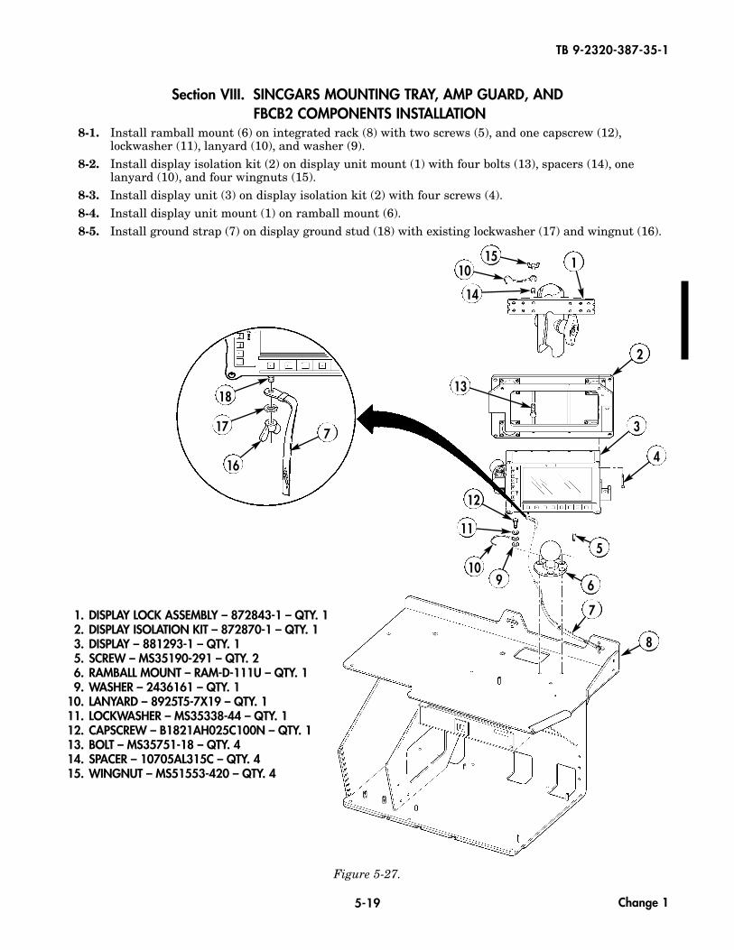
Section VIII. SINCGARS MOUNTING TRAY, AMP GUARD, AND FBCB2 COMPONENTS INSTALLATION
8-1. Install ramball mount (6) on integrated rack (8) with two screws (5), and one capscrew (12),lockwasher (11), lanyard (10), and washer (9).
8-2. Install display isolation kit (2) on display unit mount (1) with four bolts (13), spacers (14), onelanyard (10), and four wingnuts (15).
8-3. Install display unit (3) on display isolation kit (2) with four screws (4).8-4. Install display unit mount (1) on ramball mount (6).8-5. Install ground strap (7) on display ground stud (18) with existing lockwasher (17) and wingnut (16).
Figure 5-27.
1. DISPLAY LOCK ASSEMBLY – 872843-1 – QTY. 12. DISPLAY ISOLATION KIT – 872870-1 – QTY. 13. DISPLAY – 881293-1 – QTY. 15. SCREW – MS35190-291 – QTY. 26. RAMBALL MOUNT – RAM-D-111U – QTY. 19. WASHER – 2436161 – QTY. 1
10. LANYARD – 8925T5-7X19 – QTY. 111. LOCKWASHER – MS35338-44 – QTY. 112. CAPSCREW – B1821AH025C100N – QTY. 113. BOLT – MS35751-18 – QTY. 414. SPACER – 10705AL315C – QTY. 415. WINGNUT – MS51553-420 – QTY. 4
18
17
16
7
Change 1
115
2
3
4
5
6
7
8
910
11
12
13
10
14
5-20
TB 9-2320-387-35-1
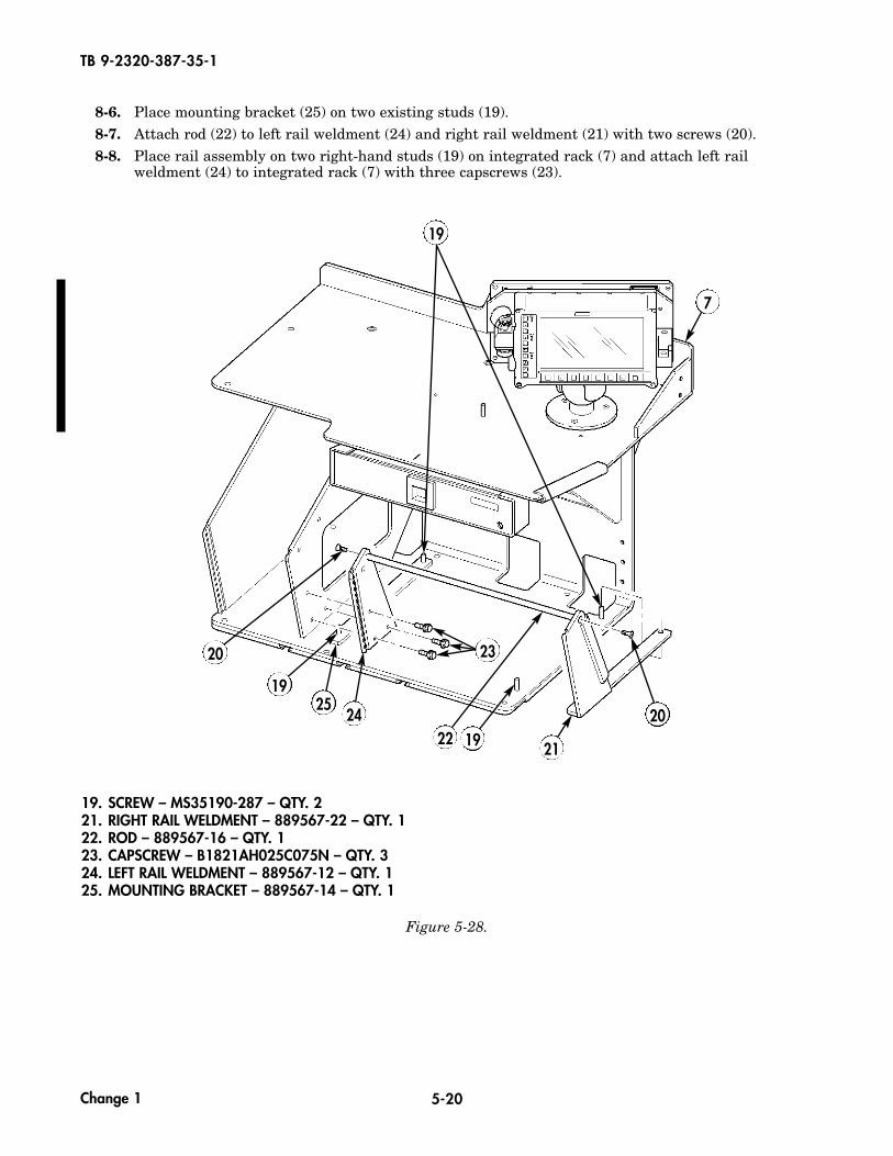
8-6. Place mounting bracket (25) on two existing studs (19).8-7. Attach rod (22) to left rail weldment (24) and right rail weldment (21) with two screws (20).8-8. Place rail assembly on two right-hand studs (19) on integrated rack (7) and attach left rail
weldment (24) to integrated rack (7) with three capscrews (23).
Figure 5-28.
19
19. SCREW – MS35190-287 – QTY. 221. RIGHT RAIL WELDMENT – 889567-22 – QTY. 122. ROD – 889567-16 – QTY. 123. CAPSCREW – B1821AH025C075N – QTY. 324. LEFT RAIL WELDMENT – 889567-12 – QTY. 125. MOUNTING BRACKET – 889567-14 – QTY. 1
19
7
20
211922
23
2425
20
Change 1
5-21
TB 9-2320-387-35-1
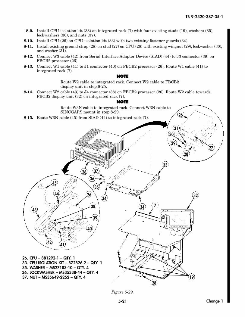
8-9. Install CPU isolation kit (33) on integrated rack (7) with four existing studs (19), washers (35),lockwashers (36), and nuts (37).
8-10. Install CPU (26) on CPU isolation kit (33) with two existing fastener guards (34).8-11. Install existing ground strap (28) on stud (27) on CPU (26) with existing wingnut (29), lockwasher (30),
and washer (31).8-12. Connect W3 cable (42) from Serial Interface Adapter Device (SIAD) (44) to J3 connector (39) on
FBCB2 processor (26).8-13. Connect W1 cable (41) to J1 connector (40) on FBCB2 processor (26). Route W1 cable (41) to
integrated rack (7).NNOOTTEE
Route W2 cable to integrated rack. Connect W2 cable to FBCB2display unit in step 8-25.
8-14. Connect W2 cable (43) to J4 connector (38) on FBCB2 processor (26). Route W2 cable towardsFBCB2 display unit (32) on integrated rack (7).
NNOOTTEERoute W3N cable to integrated rack. Connect W3N cable toSINCGARS mount in step 8-29.
8-15. Route W3N cable (45) from SIAD (44) to integrated rack (7).
Figure 5-29.
28
26
26
2728
26. CPU – 881292-1 – QTY. 133. CPU ISOLATION KIT – 872826-2 – QTY. 135. WASHER – MS27183-10 – QTY. 436. LOCKWASHER – MS35338-44 – QTY. 437. NUT – MS35649-2252 – QTY. 4
45
44 26
38
40
4142
43
32
3130
29
33
7
35
36
37
34
34
39
Change 1
19
5-22
TB 9-2320-387-35-1
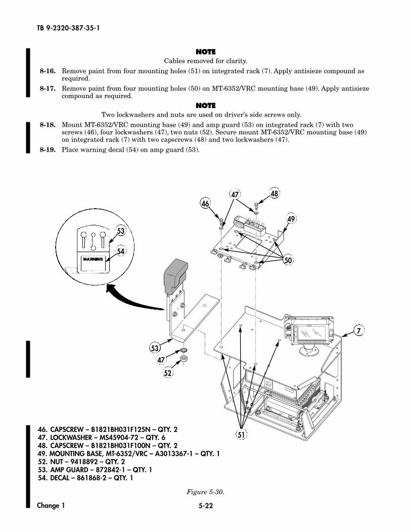
NNOOTTEECables removed for clarity.
8-16. Remove paint from four mounting holes (51) on integrated rack (7). Apply antisieze compound asrequired.
8-17. Remove paint from four mounting holes (50) on MT-6352/VRC mounting base (49). Apply antisiezecompound as required.
NNOOTTEETwo lockwashers and nuts are used on driver’s side screws only.
8-18. Mount MT-6352/VRC mounting base (49) and amp guard (53) on integrated rack (7) with twoscrews (46), four lockwashers (47), two nuts (52). Secure mount MT-6352/VRC mounting base (49)on integrated rack (7) with two capscrews (48) and two lockwashers (47).
8-19. Place warning decal (54) on amp guard (53).
Figure 5-30.
7
51
52
47
53
4648
50
49
46. CAPSCREW – B1821BH031F125N – QTY. 247. LOCKWASHER – MS45904-72 – QTY. 648. CAPSCREW – B1821BH031F100N – QTY. 249. MOUNTING BASE, MT-6352/VRC – A3013367-1 – QTY. 152. NUT – 9418892 – QTY. 253. AMP GUARD – 872842-1 – QTY. 154. DECAL – 861868-2 – QTY. 1
53
54
47
Change 1
5-23
TB 9-2320-387-35-1
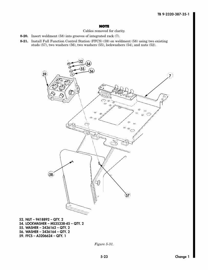
NNOOTTEECables removed for clarity.
8-20. Insert weldment (58) into grooves of integrated rack (7).8-21. Install Full Function Control Station (FFCS) (59) on weldment (58) using two existing
studs (57), two washers (56), two washers (55), lockwashers (54), and nuts (52).
Figure 5-31.
52
5559
54
567
58
57
~
Change 1
52. NUT – 9418892 – QTY. 254. LOCKWASHER – MS35338-45 – QTY. 255. WASHER – 2436162 – QTY. 256. WASHER – 2436164 – QTY. 259. FFCS – A3206624 – QTY. 1
5-24
TB 9-2320-387-35-1
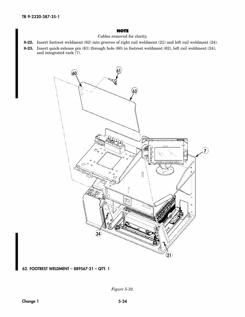
NNOOTTEECables removed for clarity.
8-22. Insert footrest weldment (62) into grooves of right rail weldment (21) and left rail weldment (24).8-23. Insert quick-release pin (61) through hole (60) in footrest weldment (62), left rail weldment (24),
and integrated rack (7).
Figure 5-32.
60 61
62
7
62. FOOTREST WELDMENT – 889567-21 – QTY. 1
21
~ 24
~
Change 1
5-24.1
TB 9-2320-387-35-1
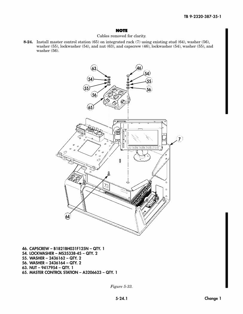
NNOOTTEECables removed for clarity.
8-24. Install master control station (65) on integrated rack (7) using existing stud (64), washer (56),washer (55), lockwasher (54), and nut (63), and capscrew (46), lockwasher (54), washer (55), andwasher (56).
Figure 5-33.
63
5556
65
54
4654
55
56
7
46. CAPSCREW – B1821BH031F125N – QTY. 154. LOCKWASHER – MS35338-45 – QTY. 255. WASHER – 2436162 – QTY. 256. WASHER – 2436164 – QTY. 263. NUT – 9417954 – QTY. 165. MASTER CONTROL STATION – A3206623 – QTY. 1
64
Change 1
5-24.2
TB 9-2320-387-35-1
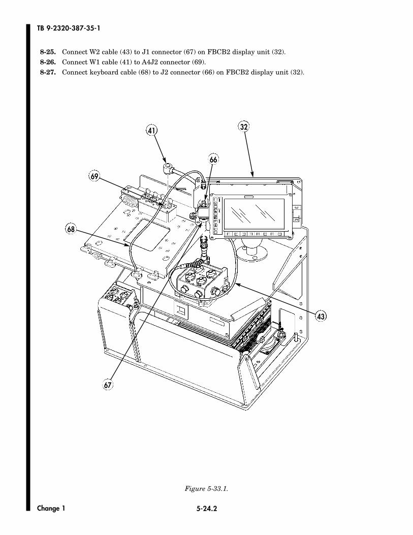
8-25. Connect W2 cable (43) to J1 connector (67) on FBCB2 display unit (32).8-26. Connect W1 cable (41) to A4J2 connector (69).8-27. Connect keyboard cable (68) to J2 connector (66) on FBCB2 display unit (32).
Figure 5-33.1.
Change 1
41 32
43
67
66
68
69
5-25 Change 1
TB 9-2320-387-35-1
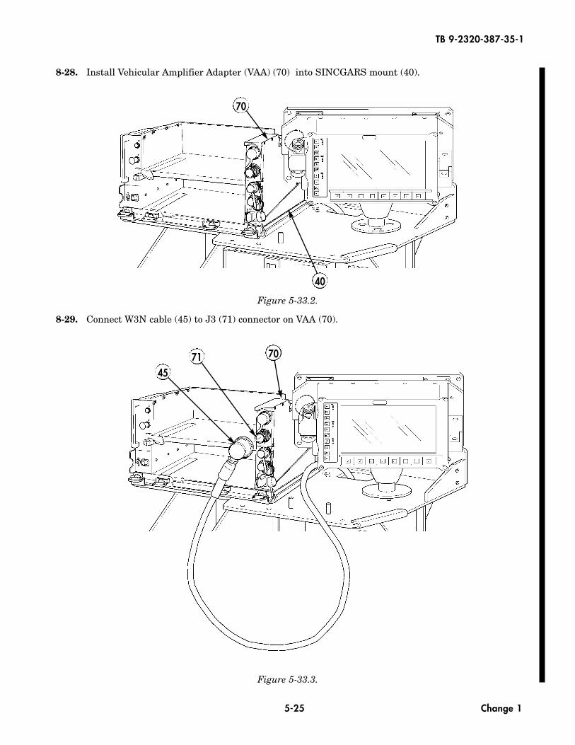
8-28. Install Vehicular Amplifier Adapter (VAA) (70) into SINCGARS mount (40).
Figure 5-33.2.
8-29. Connect W3N cable (45) to J3 (71) connector on VAA (70).
Figure 5-33.3.
70
40
707145
5-26
TB 9-2320-387-35-1
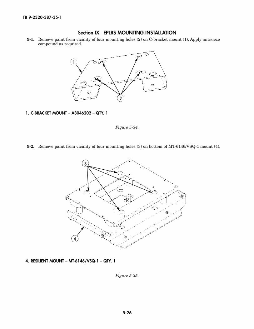
Section IX. EPLRS MOUNTING INSTALLATION9-1. Remove paint from vicinity of four mounting holes (2) on C-bracket mount (1). Apply antisieze
compound as required.
Figure 5-35.
Figure 5-34.
1
2
1. C-BRACKET MOUNT – A3046202 – QTY. 1
4. RESILIENT MOUNT – MT-6146/VSQ-1 – QTY. 1
9-2. Remove paint from vicinity of four mounting holes (3) on bottom of MT-6146/VSQ-1 mount (4).
4
3
5-27
TB 9-2320-387-35-1
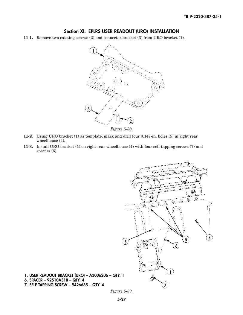
Section XI. EPLRS USER READOUT (URO) INSTALLATION11-1. Remove two existing screws (2) and connector bracket (3) from URO bracket (1).
11-2. Using URO bracket (1) as template, mark and drill four 0.147-in. holes (5) in right rearwheelhouse (4).
11-3. Install URO bracket (1) on right rear wheelhouse (4) with four self-tapping screws (7) and spacers (6).
Figure 5-39.
Figure 5-38.
1
3
2
1. USER READOUT BRACKET (URO) – A3006206 – QTY. 1 6. SPACER – 92510A318 – QTY. 47. SELF-TAPPING SCREW – 9426635 – QTY. 4
5
7
1
6
45
~
5-28
TB 9-2320-387-35-1
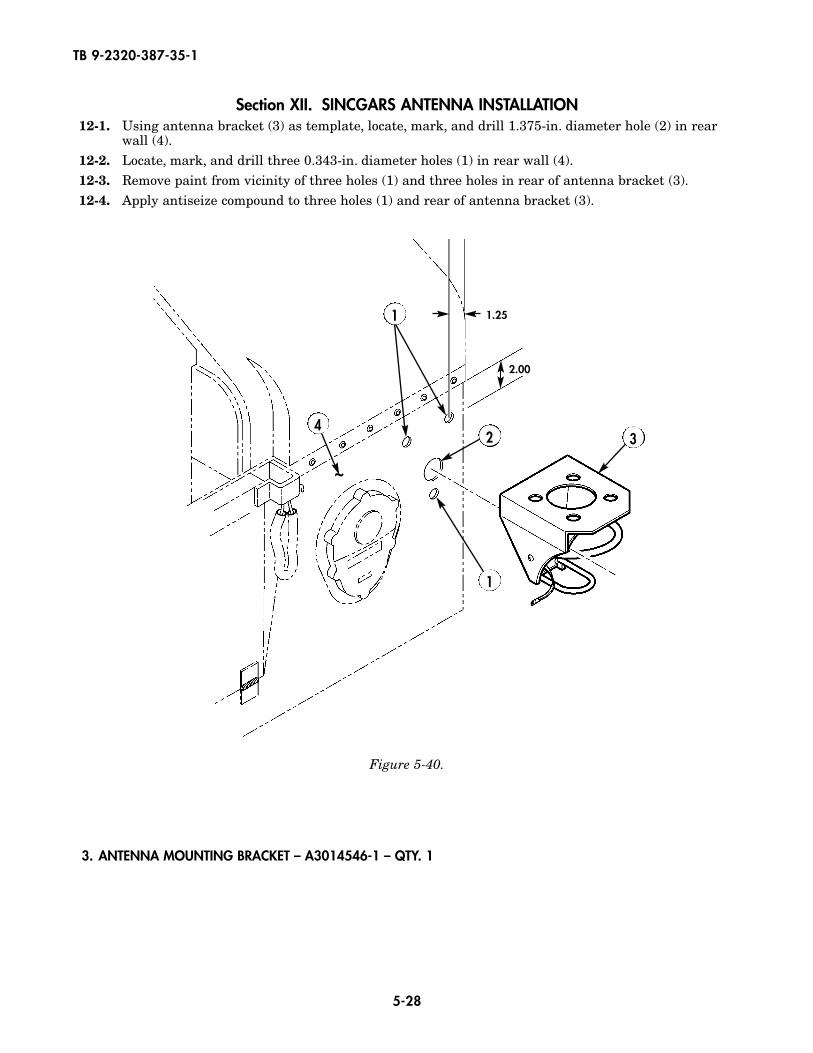
Section XII. SINCGARS ANTENNA INSTALLATION12-1. Using antenna bracket (3) as template, locate, mark, and drill 1.375-in. diameter hole (2) in rear
wall (4).12-2. Locate, mark, and drill three 0.343-in. diameter holes (1) in rear wall (4).12-3. Remove paint from vicinity of three holes (1) and three holes in rear of antenna bracket (3).12-4. Apply antiseize compound to three holes (1) and rear of antenna bracket (3).
Figure 5-40.
32
1
4
1
2.00
1.25
~
3. ANTENNA MOUNTING BRACKET – A3014546-1 – QTY. 1
5-29
TB 9-2320-387-35-1
Figure 5-41.
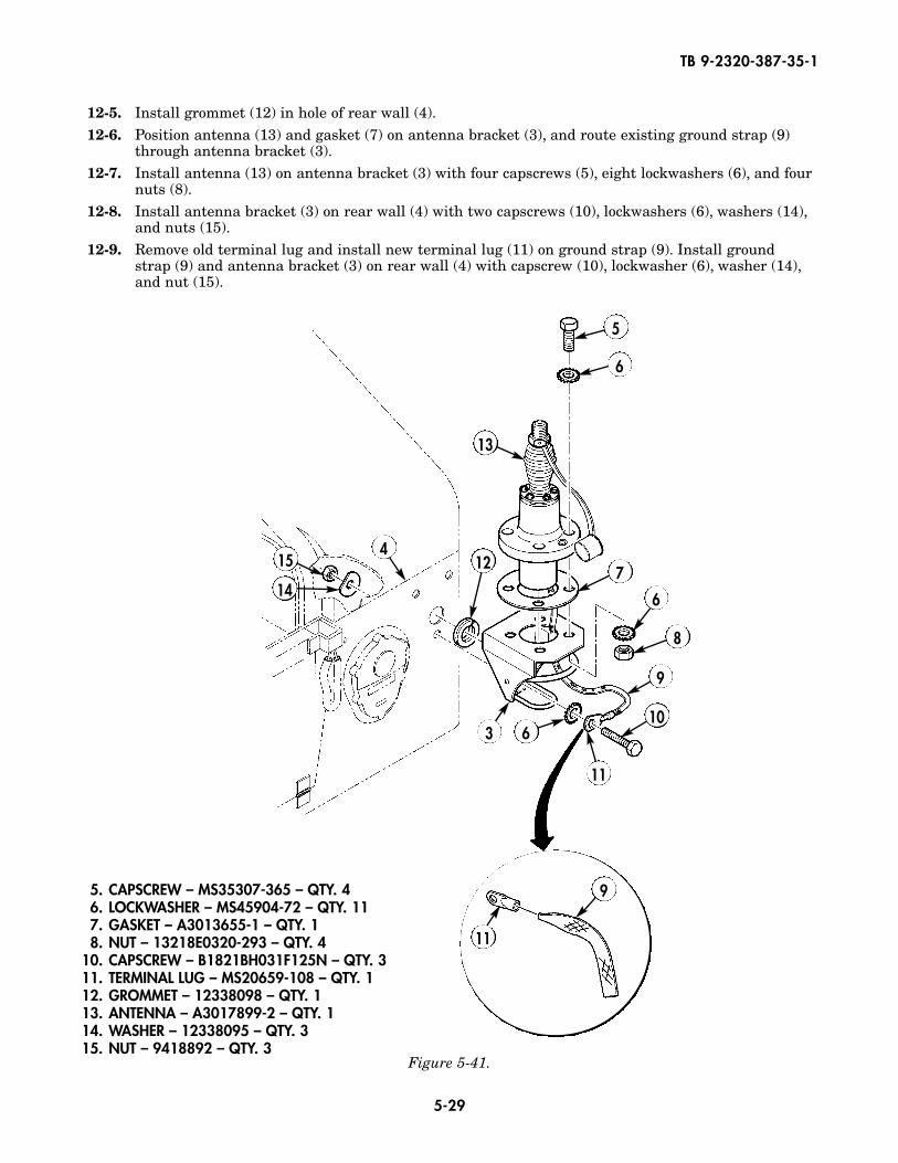
12-5. Install grommet (12) in hole of rear wall (4).12-6. Position antenna (13) and gasket (7) on antenna bracket (3), and route existing ground strap (9)
through antenna bracket (3).12-7. Install antenna (13) on antenna bracket (3) with four capscrews (5), eight lockwashers (6), and four
nuts (8).12-8. Install antenna bracket (3) on rear wall (4) with two capscrews (10), lockwashers (6), washers (14),
and nuts (15).12-9. Remove old terminal lug and install new terminal lug (11) on ground strap (9). Install ground
strap (9) and antenna bracket (3) on rear wall (4) with capscrew (10), lockwasher (6), washer (14),and nut (15).
154
13
12
6
11
310
11
9
5
6
7
6
8
9
14
5. CAPSCREW – MS35307-365 – QTY. 46. LOCKWASHER – MS45904-72 – QTY. 117. GASKET – A3013655-1 – QTY. 18. NUT – 13218E0320-293 – QTY. 4
10. CAPSCREW – B1821BH031F125N – QTY. 311. TERMINAL LUG – MS20659-108 – QTY. 112. GROMMET – 12338098 – QTY. 113. ANTENNA – A3017899-2 – QTY. 114. WASHER – 12338095 – QTY. 315. NUT – 9418892 – QTY. 3
5-30
TB 9-2320-387-35-1
Figure 5-42.
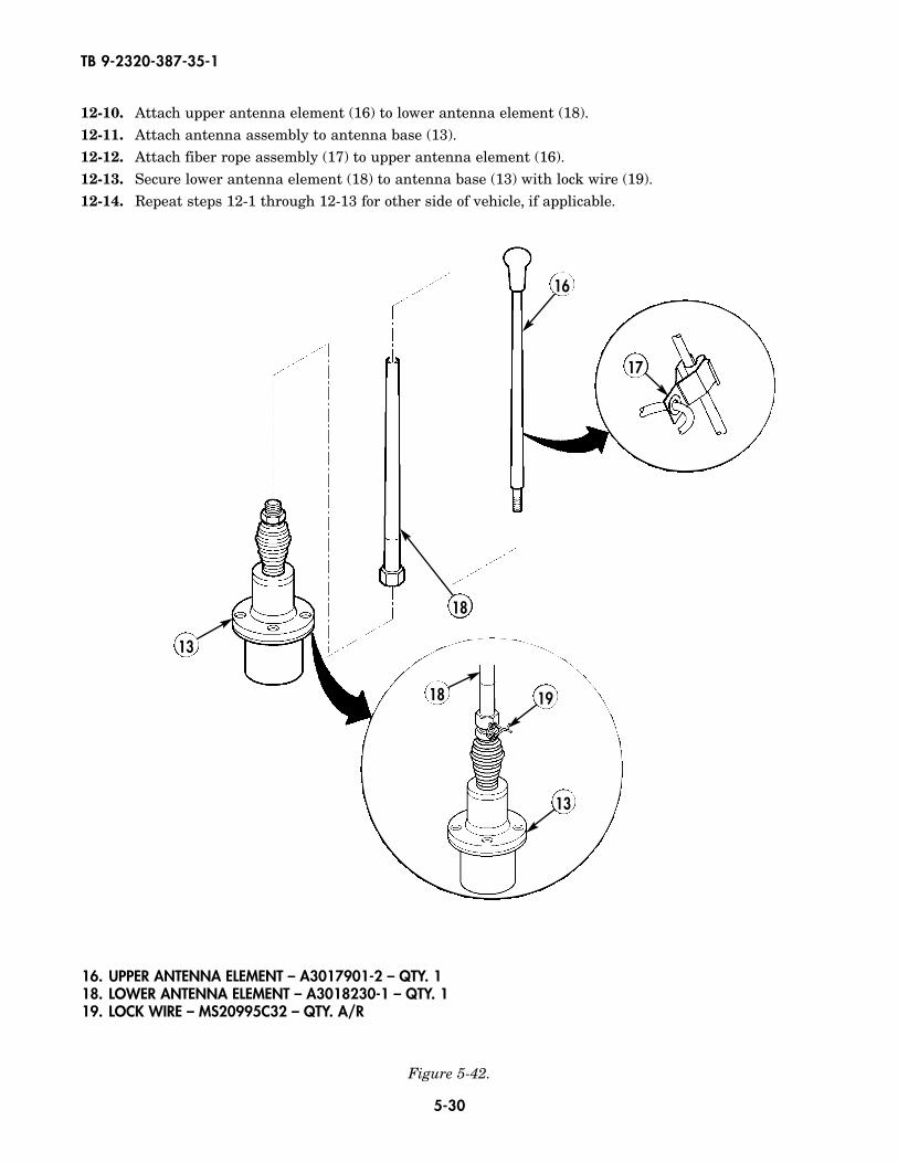
12-10. Attach upper antenna element (16) to lower antenna element (18).12-11. Attach antenna assembly to antenna base (13).12-12. Attach fiber rope assembly (17) to upper antenna element (16).12-13. Secure lower antenna element (18) to antenna base (13) with lock wire (19).12-14. Repeat steps 12-1 through 12-13 for other side of vehicle, if applicable.
16
18 19
13
17
18
13
16. UPPER ANTENNA ELEMENT – A3017901-2 – QTY. 118. LOWER ANTENNA ELEMENT – A3018230-1 – QTY. 119. LOCK WIRE – MS20995C32 – QTY. A/R

5-31
TB 9-2320-387-35-1
Figure 5-41.
12-5. Install grommet (12) in hole of rear wall (4).12-6. Position antenna (13) and gasket (7) on antenna bracket (3), and route existing ground strap (9)
through antenna bracket (3).12-7. Install antenna (13) on antenna bracket (3) with four capscrews (5), eight lockwashers (6), and four
nuts (8).12-8. Install antenna bracket (3) on rear wall (4) with two capscrews (10), lockwashers (6), washers (14),
and nuts (15).12-9. Remove old terminal lug and install new terminal lug (11) on ground strap (9). Install ground
strap (9) and antenna bracket (3) on rear wall (4) with capscrew (10), lockwasher (6), washer (14),and nut (15).
154
13
12
6
11
310
11
9
5
6
7
6
8
9
14
5. CAPSCREW – MS35307-365 – QTY. 46. LOCKWASHER – MS45904-72 – QTY. 117. GASKET – A3013655-1 – QTY. 18. NUT – 13218E0320-293 – QTY. 4
10. CAPSCREW – B1821BH031F125N – QTY. 311. TERMINAL LUG – MS20659-108 – QTY. 112. GROMMET – 12338098 – QTY. 113. ANTENNA – A3017899-2 – QTY. 114. WASHER – 12338095 – QTY. 315. NUT – 9418892 – QTY. 3
5-32
TB 9-2320-387-35-1
Figure 5-42.
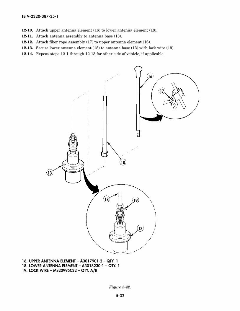
12-10. Attach upper antenna element (16) to lower antenna element (18).12-11. Attach antenna assembly to antenna base (13).12-12. Attach fiber rope assembly (17) to upper antenna element (16).12-13. Secure lower antenna element (18) to antenna base (13) with lock wire (19).12-14. Repeat steps 12-1 through 12-13 for other side of vehicle, if applicable.
16
18 19
13
17
18
13
16. UPPER ANTENNA ELEMENT – A3017901-2 – QTY. 118. LOWER ANTENNA ELEMENT – A3018230-1 – QTY. 119. LOCK WIRE – MS20995C32 – QTY. A/R
5-33
TB 9-2320-387-35-1
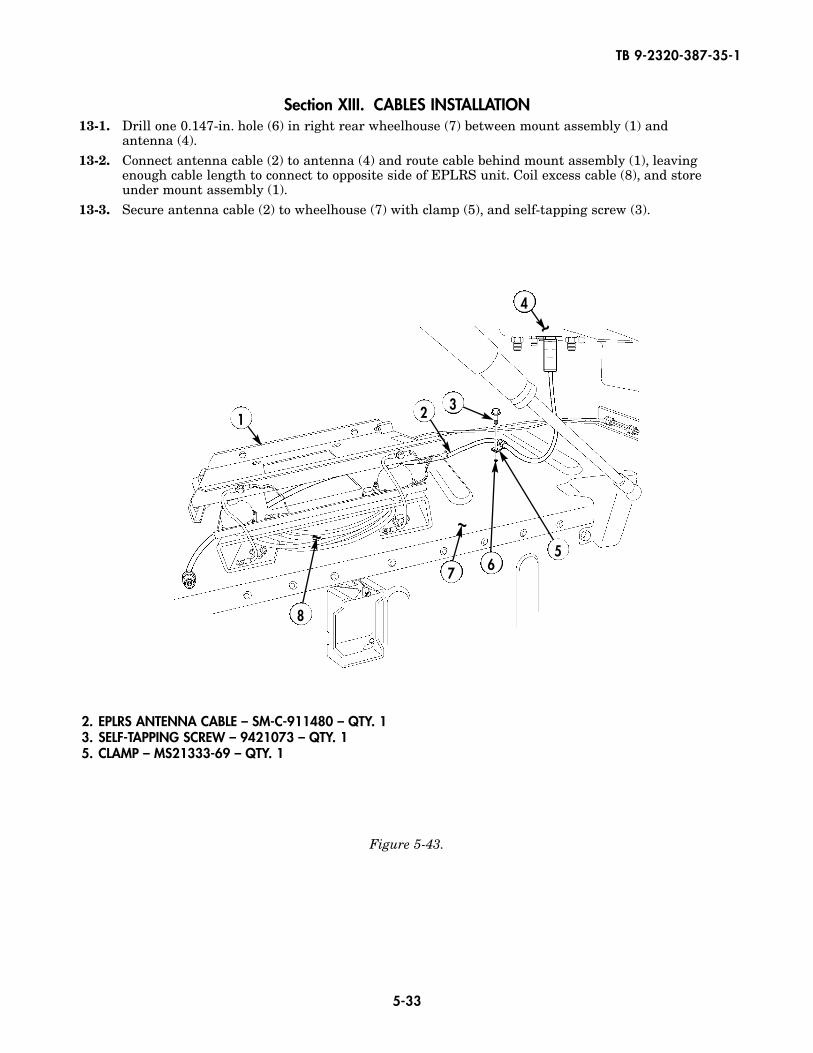
Section XIII. CABLES INSTALLATION13-1. Drill one 0.147-in. hole (6) in right rear wheelhouse (7) between mount assembly (1) and
antenna (4).13-2. Connect antenna cable (2) to antenna (4) and route cable behind mount assembly (1), leaving
enough cable length to connect to opposite side of EPLRS unit. Coil excess cable (8), and storeunder mount assembly (1).
13-3. Secure antenna cable (2) to wheelhouse (7) with clamp (5), and self-tapping screw (3).
Figure 5-43.
~
~ ~
1
4
2 3
567
8
2. EPLRS ANTENNA CABLE – SM-C-911480 – QTY. 1 3. SELF-TAPPING SCREW – 9421073 – QTY. 1 5. CLAMP – MS21333-69 – QTY. 1
5-34
TB 9-2320-387-35-1
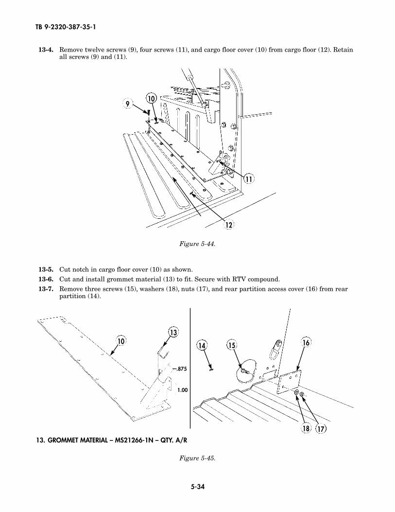
13-4. Remove twelve screws (9), four screws (11), and cargo floor cover (10) from cargo floor (12). Retainall screws (9) and (11).
13-5. Cut notch in cargo floor cover (10) as shown.13-6. Cut and install grommet material (13) to fit. Secure with RTV compound.13-7. Remove three screws (15), washers (18), nuts (17), and rear partition access cover (16) from rear
partition (14).
Figure 5-45.
Figure 5-44.
12
~
~
910
11
13. GROMMET MATERIAL – MS21266-1N – QTY. A/R
~
14 151013
16
1718
.875
1.00
5-35
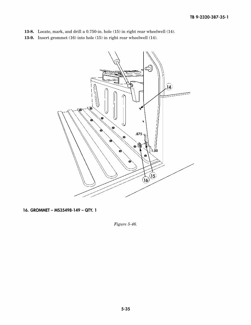
13-8. Locate, mark, and drill a 0.750-in. hole (15) in right rear wheelwell (14).13-9. Insert grommet (16) into hole (15) in right rear wheelwell (14).
Figure 5-46.
~
14
16
16. GROMMET – MS35498-149 – QTY. 1
1.00
.875
15
TB 9-2320-387-35-1
5-36
TB 9-2320-387-35-1
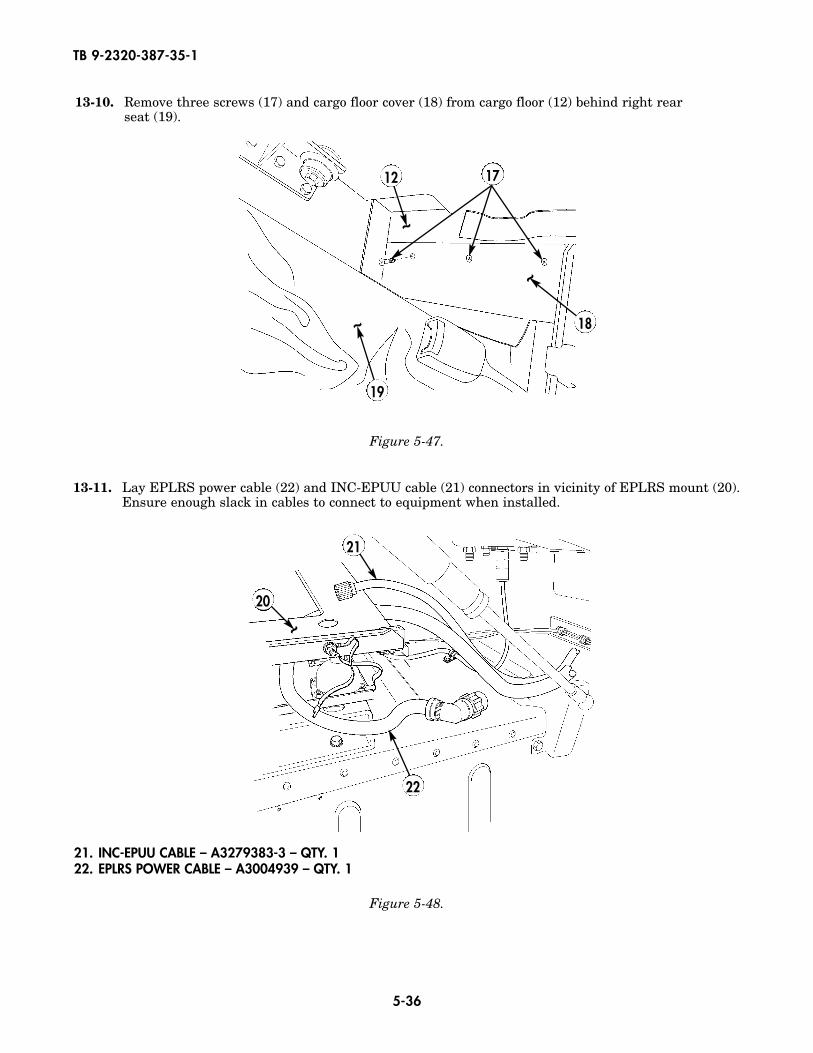
13-10. Remove three screws (17) and cargo floor cover (18) from cargo floor (12) behind right rear seat (19).
Figure 5-48.
Figure 5-47.
~ 20
21
22
21. INC-EPUU CABLE – A3279383-3 – QTY. 122. EPLRS POWER CABLE – A3004939 – QTY. 1
13-11. Lay EPLRS power cable (22) and INC-EPUU cable (21) connectors in vicinity of EPLRS mount (20).Ensure enough slack in cables to connect to equipment when installed.
19
~
~
~
12 17
18
5-37
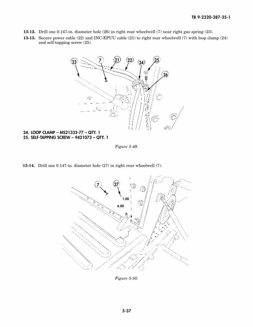
13-12. Drill one 0.147-in. diameter hole (26) in right rear wheelwell (7) near right gas spring (23).13-13. Secure power cable (22) and INC-EPUU cable (21) to right rear wheelwell (7) with loop clamp (24)
and self-tapping screw (25).
Figure 5-50.
Figure 5-49.
~
6.00
1.00
7 27
24. LOOP CLAMP – MS21333-77 – QTY. 125. SELF-TAPPING SCREW – 9421073 – QTY. 1
13-14. Drill one 0.147-in. diameter hole (27) in right rear wheelwell (7).
~
7 21 22 2423 25
26
TB 9-2320-387-35-1
5-38
TB 9-2320-387-35-1
Figure 5-51.
~
~
7
22
21
29
28
30
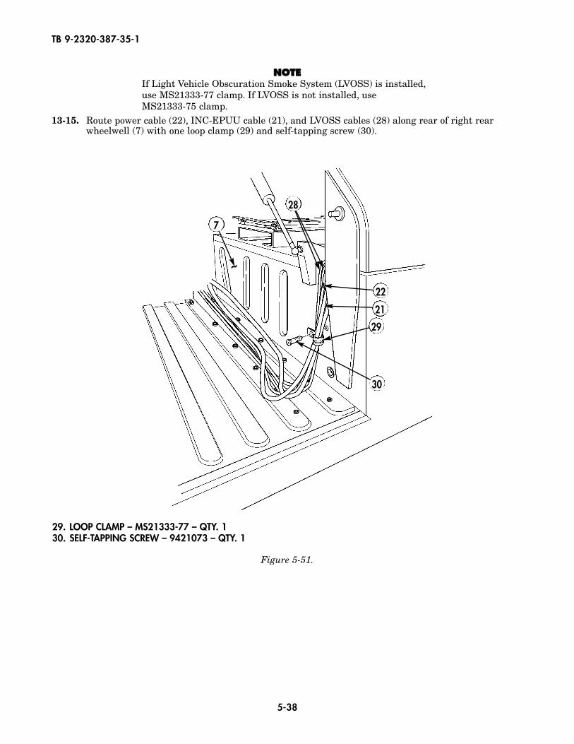
29. LOOP CLAMP – MS21333-77 – QTY. 130. SELF-TAPPING SCREW – 9421073 – QTY. 1
NNOOTTEEIf Light Vehicle Obscuration Smoke System (LVOSS) is installed,use MS21333-77 clamp. If LVOSS is not installed, use MS21333-75 clamp.
13-15. Route power cable (22), INC-EPUU cable (21), and LVOSS cables (28) along rear of right rearwheelwell (7) with one loop clamp (29) and self-tapping screw (30).
5-39
TB 9-2320-387-35-1
Figure 5-52.
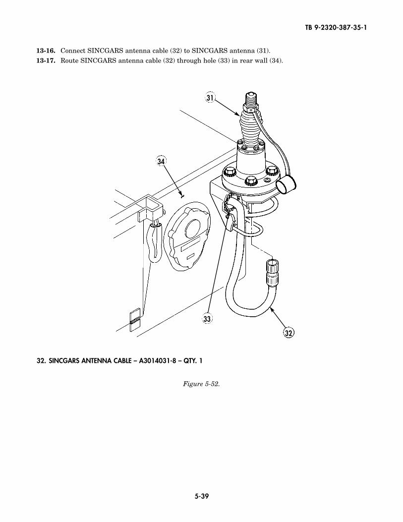
32. SINCGARS ANTENNA CABLE – A3014031-8 – QTY. 1
13-16. Connect SINCGARS antenna cable (32) to SINCGARS antenna (31).13-17. Route SINCGARS antenna cable (32) through hole (33) in rear wall (34).
~
34
31
33
32
5-40
TB 9-2320-387-35-1
Figure 5-53.
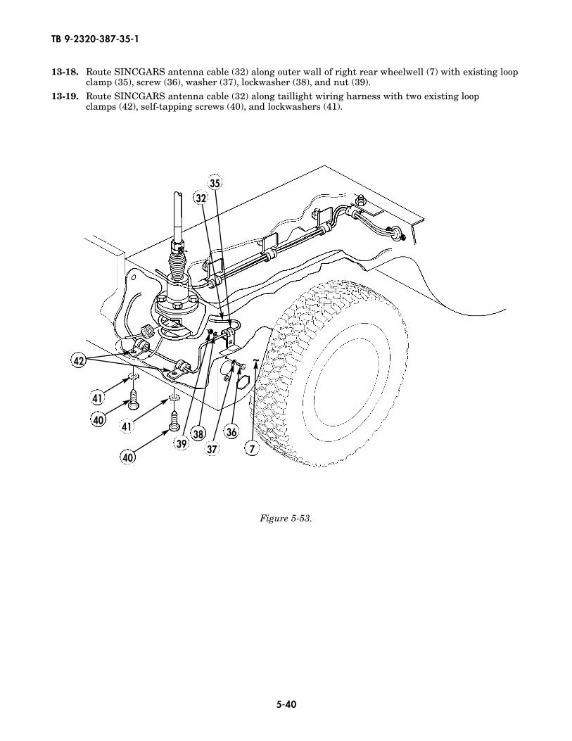
13-18. Route SINCGARS antenna cable (32) along outer wall of right rear wheelwell (7) with existing loopclamp (35), screw (36), washer (37), lockwasher (38), and nut (39).
13-19. Route SINCGARS antenna cable (32) along taillight wiring harness with two existing loop clamps (42), self-tapping screws (40), and lockwashers (41).
42
41
40
3235
3938
37
36
7
~
41
40
5-41
TB 9-2320-387-35-1
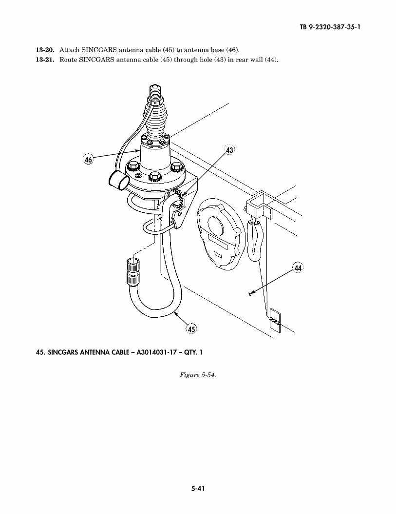
Figure 5-54.
13-20. Attach SINCGARS antenna cable (45) to antenna base (46).13-21. Route SINCGARS antenna cable (45) through hole (43) in rear wall (44).
4643
44
45
45. SINCGARS ANTENNA CABLE – A3014031-17 – QTY. 1
~
5-42
TB 9-2320-387-35-1
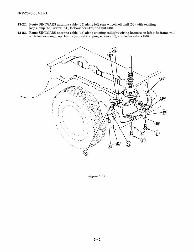
Figure 5-55.
13-22. Route SINCGARS antenna cable (45) along left rear wheelwell wall (53) with existing loop clamp (55), screw (54), lockwasher (47), and nut (48).
13-23. Route SINCGARS antenna cable (45) along existing taillight wiring harness on left side frame railwith two existing loop clamps (49), self-tapping screws (51), and lockwashers (50).
4748
45
49
50
5150
51
55
5453 52
~
49
5-43
TB 9-2320-387-35-1
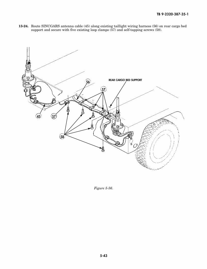
Figure 5-56.
13-24. Route SINCGARS antenna cable (45) along existing taillight wiring harness (56) on rear cargo bedsupport and secure with five existing loop clamps (57) and self-tapping screws (58).
56
5745
57
58
REAR CARGO BED SUPPORT
~
5-44
TB 9-2320-387-35-1
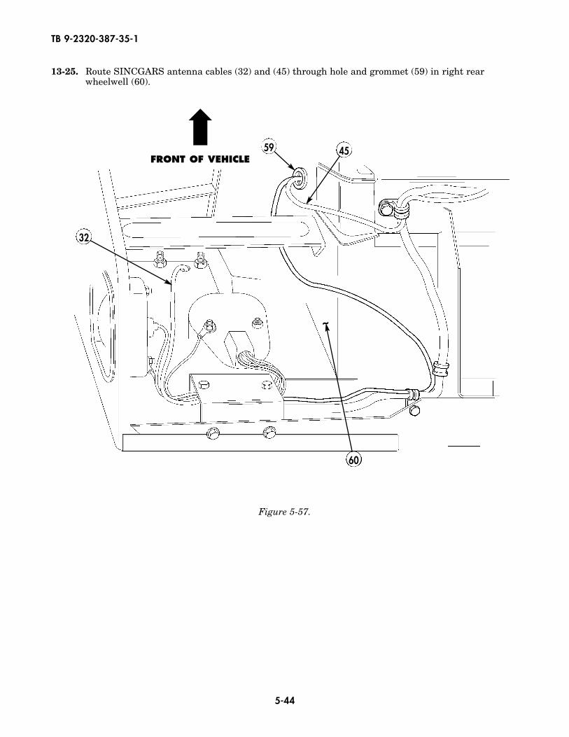
Figure 5-57.
13-25. Route SINCGARS antenna cables (32) and (45) through hole and grommet (59) in right rearwheelwell (60).
59
32
45
60
~
FRONT OF VEHICLE
➡
5-45
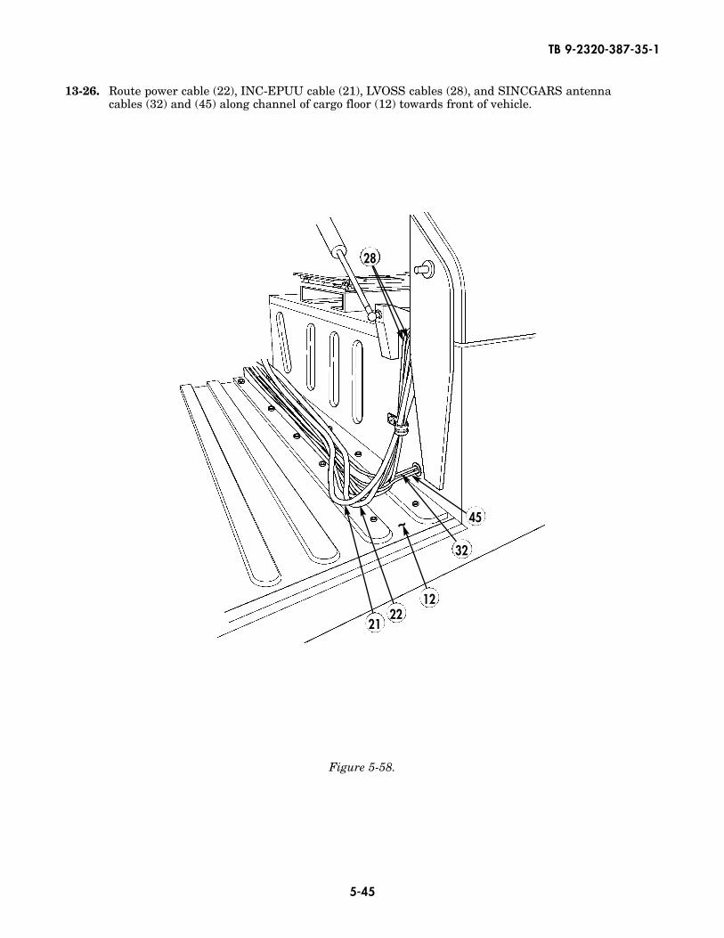
Figure 5-58.
~
2221
45
28
12
13-26. Route power cable (22), INC-EPUU cable (21), LVOSS cables (28), and SINCGARS antennacables (32) and (45) along channel of cargo floor (12) towards front of vehicle.
TB 9-2320-387-35-1
32
5-46
TB 9-2320-387-35-1
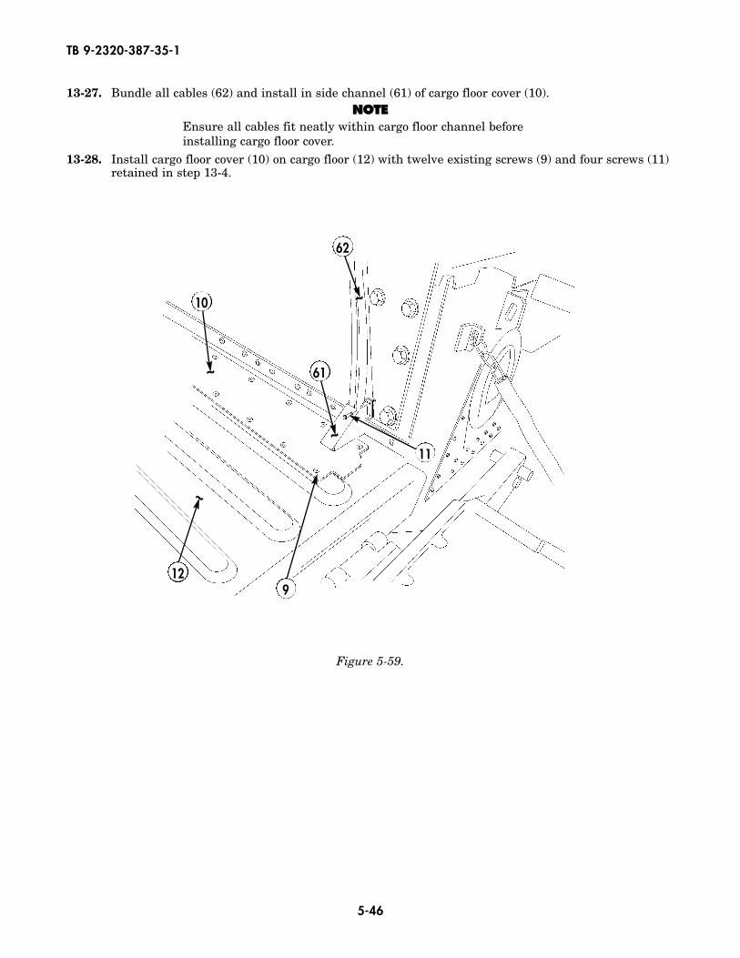
Figure 5-59.
13-27. Bundle all cables (62) and install in side channel (61) of cargo floor cover (10).NNOOTTEE
Ensure all cables fit neatly within cargo floor channel beforeinstalling cargo floor cover.
13-28. Install cargo floor cover (10) on cargo floor (12) with twelve existing screws (9) and four screws (11)retained in step 13-4.
~
~
~
~
61
62
11
912
10
5-47
68. LOOP CLAMP – MS21333-75 – QTY. 369. SELF-TAPPING SCREW – 9421073 – QTY. 2
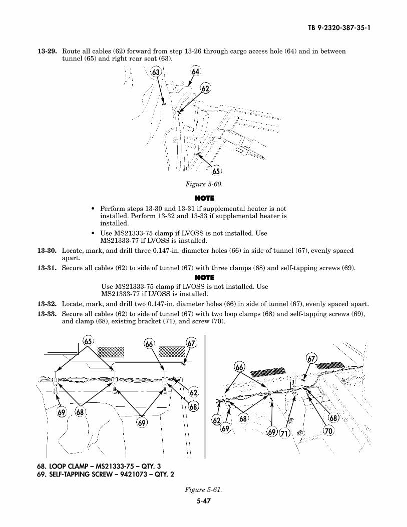
13-29. Route all cables (62) forward from step 13-26 through cargo access hole (64) and in betweentunnel (65) and right rear seat (63).
Figure 5-60.
NNOOTTEE• Perform steps 13-30 and 13-31 if supplemental heater is not
installed. Perform 13-32 and 13-33 if supplemental heater isinstalled.
• Use MS21333-75 clamp if LVOSS is not installed. UseMS21333-77 if LVOSS is installed.
13-30. Locate, mark, and drill three 0.147-in. diameter holes (66) in side of tunnel (67), evenly spacedapart.
13-31. Secure all cables (62) to side of tunnel (67) with three clamps (68) and self-tapping screws (69).NNOOTTEE
Use MS21333-75 clamp if LVOSS is not installed. UseMS21333-77 if LVOSS is installed.
13-32. Locate, mark, and drill two 0.147-in. diameter holes (66) in side of tunnel (67), evenly spaced apart.13-33. Secure all cables (62) to side of tunnel (67) with two loop clamps (68) and self-tapping screws (69),
and clamp (68), existing bracket (71), and screw (70).
~ ~
~
64
62
63
65
Figure 5-61.
~
~
~
66
62
6765
68
696869
68
6766
7071696962 68
~
TB 9-2320-387-35-1
Change 1 5-48
TB 9-2320-387-35-1
Figure 5-63.
89
83
87
85
86
88
Figure 5-62.
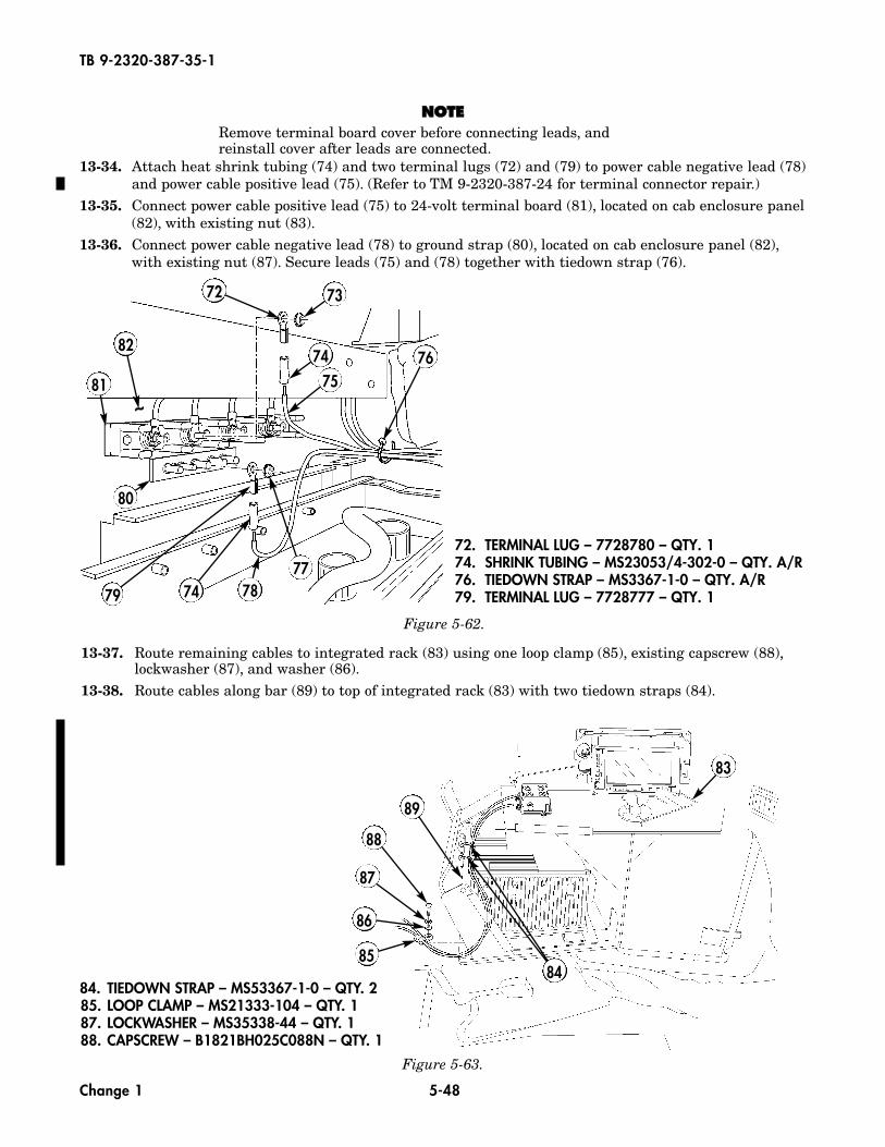
13-37. Route remaining cables to integrated rack (83) using one loop clamp (85), existing capscrew (88),lockwasher (87), and washer (86).
13-38. Route cables along bar (89) to top of integrated rack (83) with two tiedown straps (84).
84. TIEDOWN STRAP – MS53367-1-0 – QTY. 285. LOOP CLAMP – MS21333-104 – QTY. 187. LOCKWASHER – MS35338-44 – QTY. 188. CAPSCREW – B1821BH025C088N – QTY. 1
NNOOTTEERemove terminal board cover before connecting leads, andreinstall cover after leads are connected.
13-34. Attach heat shrink tubing (74) and two terminal lugs (72) and (79) to power cable negative lead (78)and power cable positive lead (75). (Refer to TM 9-2320-387-24 for terminal connector repair.)
13-35. Connect power cable positive lead (75) to 24-volt terminal board (81), located on cab enclosure panel(82), with existing nut (83).
13-36. Connect power cable negative lead (78) to ground strap (80), located on cab enclosure panel (82),with existing nut (87). Secure leads (75) and (78) together with tiedown strap (76).
72 73
7475
8276
77787479
80
81~
72. TERMINAL LUG – 7728780 – QTY. 174. SHRINK TUBING – MS23053/4-302-0 – QTY. A/R76. TIEDOWN STRAP – MS3367-1-0 – QTY. A/R79. TERMINAL LUG – 7728777 – QTY. 1
84
5-48.1
TB 9-2320-387-35-1
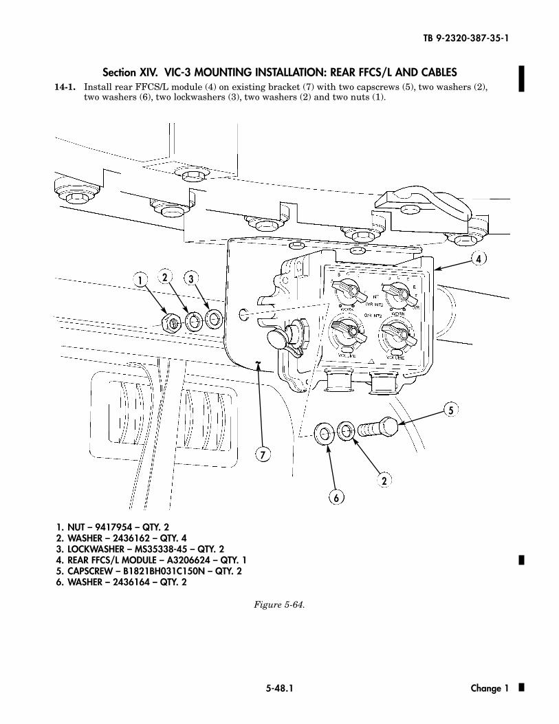
Section XIV. VIC-3 MOUNTING INSTALLATION: REAR FFCS/L AND CABLES14-1. Install rear FFCS/L module (4) on existing bracket (7) with two capscrews (5), two washers (2),
two washers (6), two lockwashers (3), two washers (2) and two nuts (1).
Figure 5-64.
~
1 2 3
4
6
7
1. NUT – 9417954 – QTY. 22. WASHER – 2436162 – QTY. 4 3. LOCKWASHER – MS35338-45 – QTY. 24. REAR FFCS/L MODULE – A3206624 – QTY. 15. CAPSCREW – B1821BH031C150N – QTY. 26. WASHER – 2436164 – QTY. 2
5
2
Change 1
5-48.2
TB 9-2320-387-35-1
NNOOTTEECables removed for clarity.
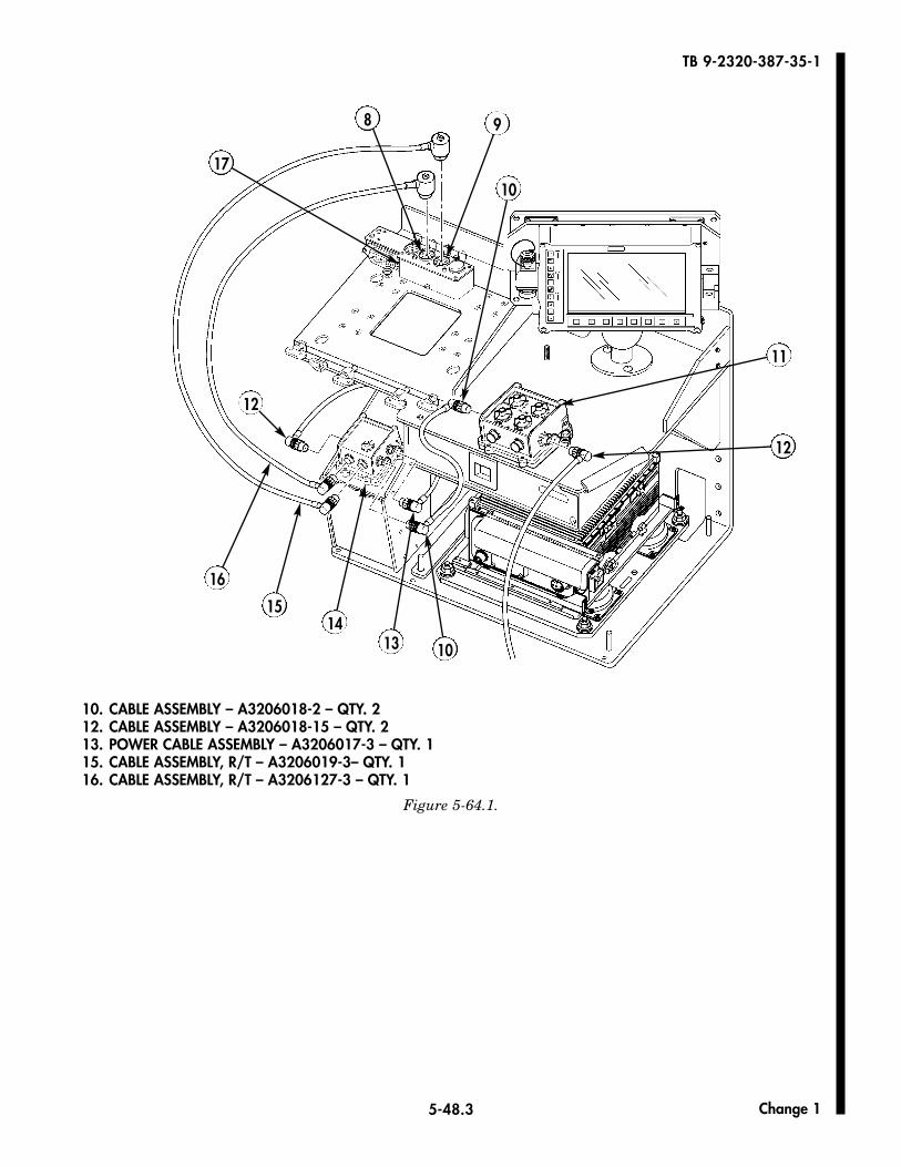
14-2. Install cable assembly (10) to front FFCS/L (11).14-3. Install cable assembly (10) to MCS/L (14).14-4. Install cable assembly (12) to front FFCS/L (11).14-5. Install cable assembly (12) to MCS/L (14).14-6. Install power cable assembly (13) to MCS/L (14).14-7. Install R/T cable assembly (15) to MCS/L (14). Connect R/T cable assembly (15) to A4J4 connector (9)
on SINCGARS mount (17).14-8. Install R/T cable assembly (16) to MCS/L (14). Connect R/T cable assembly (16) to A4J3 connector (8)
on SINCGARS mount (17).
Change 1
5-48.3
TB 9-2320-387-35-1
10. CABLE ASSEMBLY – A3206018-2 – QTY. 212. CABLE ASSEMBLY – A3206018-15 – QTY. 213. POWER CABLE ASSEMBLY – A3206017-3 – QTY. 1 15. CABLE ASSEMBLY, R/T – A3206019-3– QTY. 116. CABLE ASSEMBLY, R/T – A3206127-3 – QTY. 1
Figure 5-64.1.
8 9
11
12
13 10
10
1415
16
12
17
Change 1
5-48.4
TB 9-2320-387-35-1
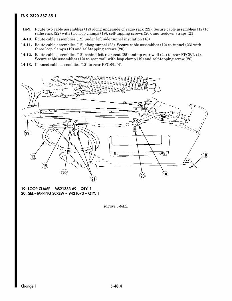
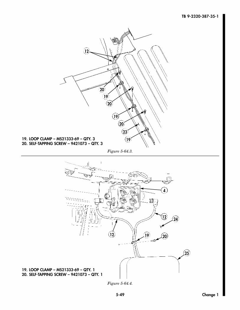
14-9. Route two cable assemblies (12) along underside of radio rack (22). Secure cable assemblies (12) to radio rack (22) with two loop clamps (19), self-tapping screws (20), and tiedown straps (21).
14-10. Route cable assemblies (12) under left side tunnel insulation (18).14-11. Route cable assemblies (12) along tunnel (23). Secure cable assemblies (12) to tunnel (23) with
three loop clamps (19) and self-tapping screws (20).14-12. Route cable assemblies (12) behind left rear seat (25) and up rear wall (24) to rear FFCS/L (4).
Secure cable assemblies (12) to rear wall with loop clamp (19) and self-tapping screw (20).14-13. Connect cable assemblies (12) to rear FFCS/L (4).
Figure 5-64.2.
19. LOOP CLAMP – MS21333-69 – QTY. 120. SELF-TAPPING SCREW – 9421073 – QTY. 1
~
18
192021
2019
12
22
Change 1
5-49
TB 9-2320-387-35-1
Figure 5-64.3.
12
19
20 ~
23
19
20
19
20
4
12
19 20
~
24
25
12
Figure 5-64.4.
19. LOOP CLAMP – MS21333-69 – QTY. 320. SELF-TAPPING SCREW – 9421073 – QTY. 3
19. LOOP CLAMP – MS21333-69 – QTY. 120. SELF-TAPPING SCREW – 9421073 – QTY. 1
Change 1
5-50
TB 9-2320-387-35-1
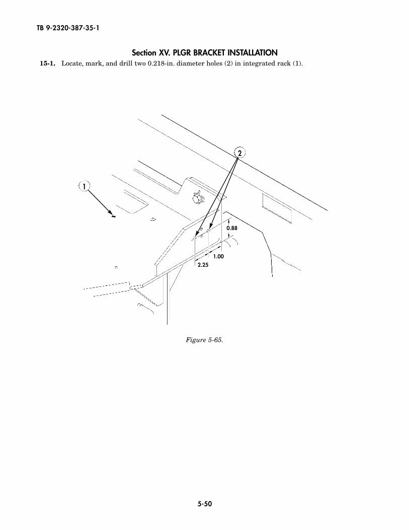
Section XV. PLGR BRACKET INSTALLATION15-1. Locate, mark, and drill two 0.218-in. diameter holes (2) in integrated rack (1).
Figure 5-65.
2
1
0.88
1.002.25
~
5-51
TB 9-2320-387-35-1
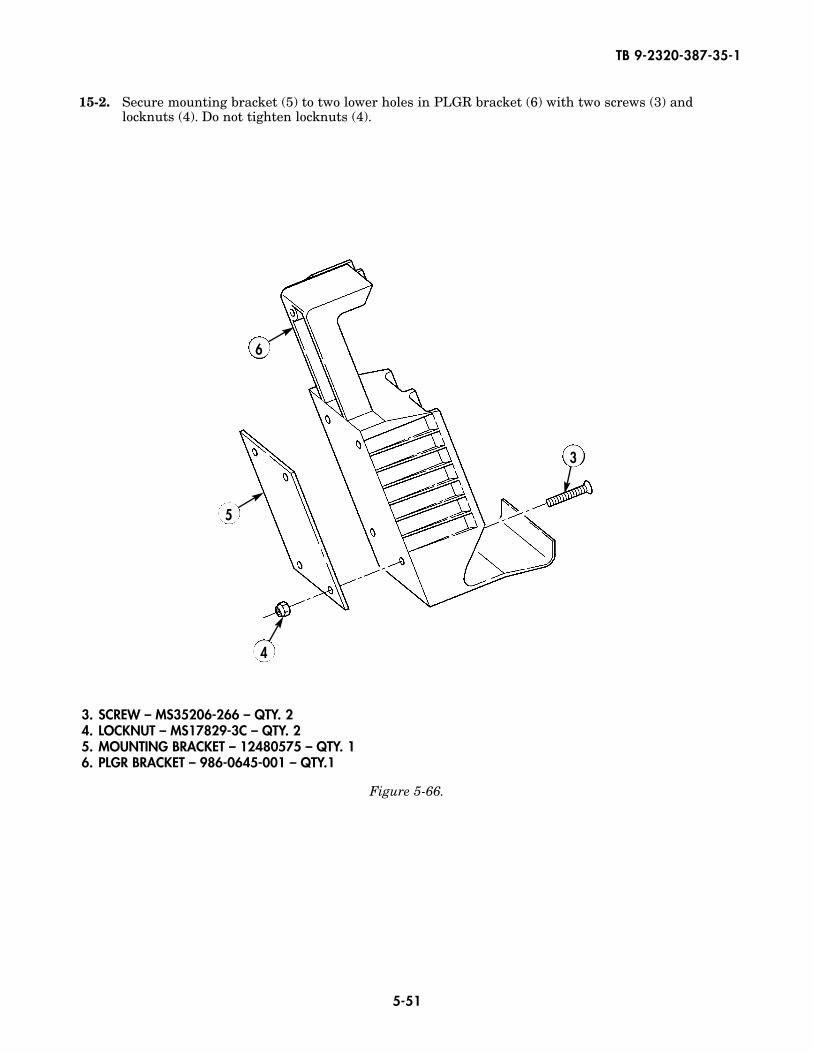
15-2. Secure mounting bracket (5) to two lower holes in PLGR bracket (6) with two screws (3) andlocknuts (4). Do not tighten locknuts (4).
Figure 5-66.
3. SCREW – MS35206-266 – QTY. 24. LOCKNUT – MS17829-3C – QTY. 25. MOUNTING BRACKET – 12480575 – QTY. 16. PLGR BRACKET – 986-0645-001 – QTY.1
3
6
5
4
5-52
TB 9-2320-387-35-1
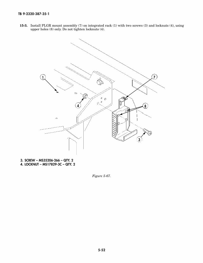
15-3. Install PLGR mount assembly (7) on integrated rack (1) with two screws (3) and locknuts (4), usingupper holes (8) only. Do not tighten locknuts (4).
Figure 5-67.
3. SCREW – MS35206-266 – QTY. 24. LOCKNUT – MS17829-3C – QTY. 2
3
7
4 8
1
~
5-53
TB 9-2320-387-35-1
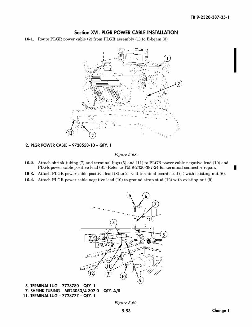
Section XVI. PLGR POWER CABLE INSTALLATION16-1. Route PLGR power cable (2) from PLGR assembly (1) to B-beam (3).
Figure 5-69.
5. TERMINAL LUG – 7728780 – QTY. 17. SHRINK TUBING – MS23053/4-302-0 – QTY. A/R
11. TERMINAL LUG – 7728777 – QTY. 1
Figure 5-68.
16-2. Attach shrink tubing (7) and terminal lugs (5) and (11) to PLGR power cable negative lead (10) andPLGR power cable positive lead (8). (Refer to TM 9-2320-387-24 for terminal connector repair.)
16-3. Attach PLGR power cable positive lead (8) to 24-volt terminal board stud (4) with existing nut (6).16-4. Attach PLGR power cable negative lead (10) to ground strap stud (12) with existing nut (9).
2. PLGR POWER CABLE – 9728558-10 – QTY. 1
8
9
65
7
10
11
712
4
~
13 2
1
2
Change 1
5-54
TB 9-2320-387-35-1
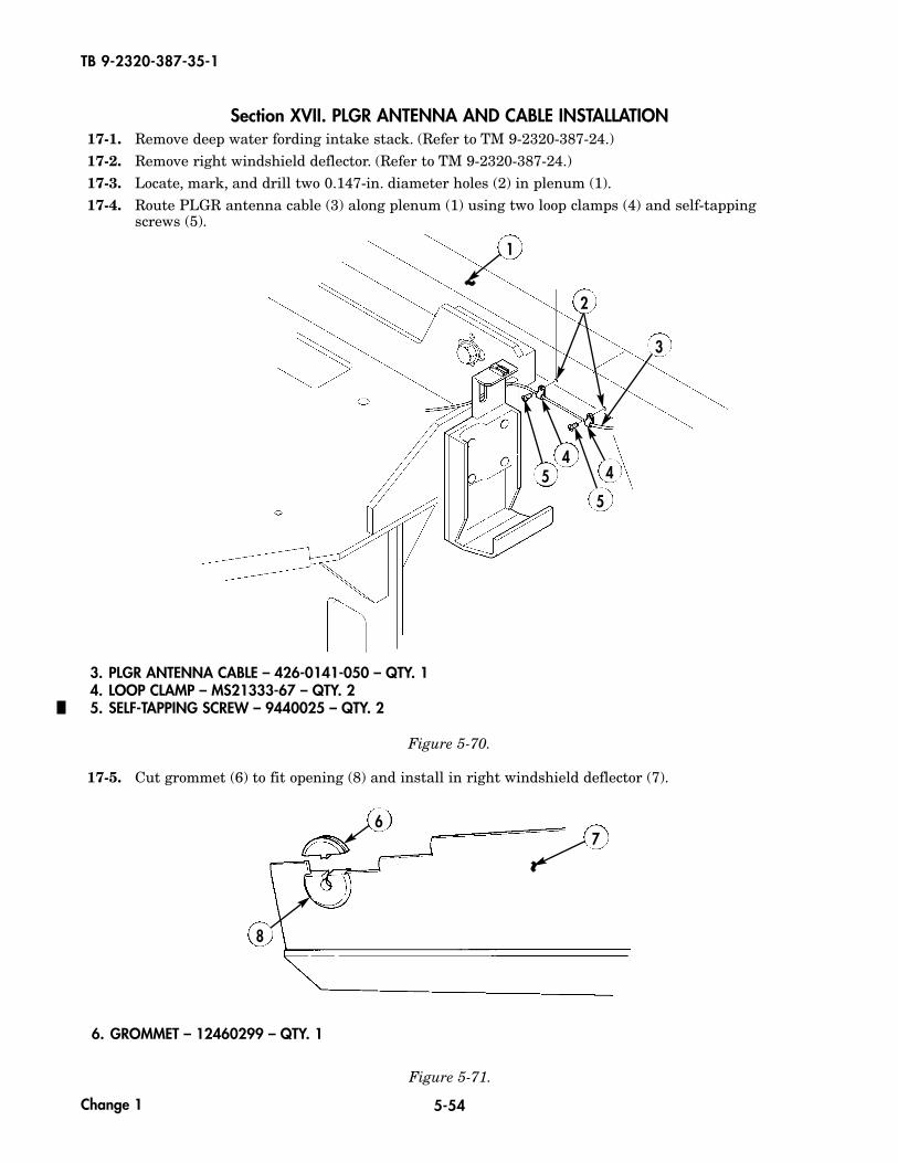
Section XVII. PLGR ANTENNA AND CABLE INSTALLATION17-1. Remove deep water fording intake stack. (Refer to TM 9-2320-387-24.)17-2. Remove right windshield deflector. (Refer to TM 9-2320-387-24.)17-3. Locate, mark, and drill two 0.147-in. diameter holes (2) in plenum (1).17-4. Route PLGR antenna cable (3) along plenum (1) using two loop clamps (4) and self-tapping
screws (5).
Figure 5-71.
6. GROMMET – 12460299 – QTY. 1
Figure 5-70.
3. PLGR ANTENNA CABLE – 426-0141-050 – QTY. 14. LOOP CLAMP – MS21333-67 – QTY. 25. SELF-TAPPING SCREW – 9440025 – QTY. 2
3
1
44
55
2
17-5. Cut grommet (6) to fit opening (8) and install in right windshield deflector (7).
67
8
~~
~~
Change 1
5-55
TB 9-2320-387-35-1
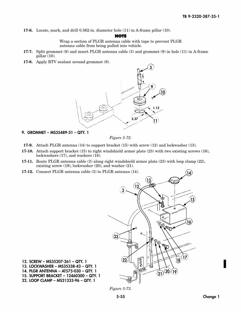
17-6. Locate, mark, and drill 0.562-in. diameter hole (11) in A-frame pillar (10).NNOOTTEE
Wrap a section of PLGR antenna cable with tape to prevent PLGRantenna cable from being pulled into vehicle.
17-7. Split grommet (9) and insert PLGR antenna cable (3) and grommet (9) in hole (11) in A-framepillar (10).
17-8. Apply RTV sealant around grommet (9).
Figure 5-73.
12. SCREW – MS35207-261 – QTY. 113. LOCKWASHER – MS35338-43 – QTY. 114. PLGR ANTENNA – AT575-030 – QTY. 115. SUPPORT BRACKET – 12460300 – QTY. 122. LOOP CLAMP – MS21333-96 – QTY. 1
3
910
11
1.12
2.37
Figure 5-72.
17-9. Attach PLGR antenna (14) to support bracket (15) with screw (12) and lockwasher (13).17-10. Attach support bracket (15) to right windshield armor plate (23) with two existing screws (16),
lockwashers (17), and washers (18).17-11. Route PLGR antenna cable (3) along right windshield armor plate (23) with loop clamp (22),
existing screw (19), lockwasher (20), and washer (21).17-12. Connect PLGR antenna cable (3) to PLGR antenna (14).
9. GROMMET – MS35489-31 – QTY. 1
14
15
16
21
22
23
3
20 19
1817
1213
~
~
Change 1
5-56
TB 9-2320-387-35-1
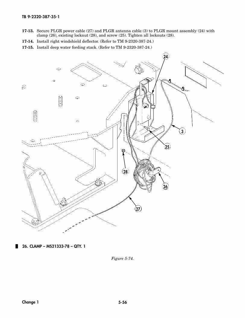
17-13. Secure PLGR power cable (27) and PLGR antenna cable (3) to PLGR mount assembly (24) withclamp (26), existing locknut (28), and screw (25). Tighten all locknuts (28).
17-14. Install right windshield deflector. (Refer to TM 9-2320-387-24.)17-15. Install deep water fording stack. (Refer to TM 9-2320-387-24.)
Figure 5-74.
26. CLAMP – MS21333-78 – QTY. 1
3
24
26
27
28
25
Change 1
Distribution:
To be distributed in accordance with the Initial Distribution Number (IDN) 344826 requirements for TB 9-2320-387-35-1.
By Order of the Secretary of the Army:
PETER J. SCHOOMAKERGeneral, United States Army
Chief of Staff
SANDRA R. RILEYAdministrative Assistant to the
Secretary of the Army0520913
Official:

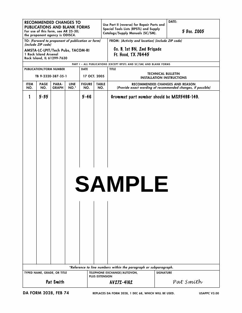
RECOMMENDED CHANGES TO PUBLICATIONS AND BLANK FORMSFor use of this form, see AR 25-30; the proponent agency is ODISC4.
Use Part II (reverse) for Repair Parts andSpecial Tools Lists (RPSTL) and SupplyCatalogs/Supply Manuals (SC/SM).
DATE:
5 Dec. 2005
TO: (Forward to proponent of publication or form) (include ZIP code)
AMSTA-LC-LPIT/Tech Pubs, TACOM-RI1 Rock Island ArsenalRock Island, IL 61299-7630
FROM: (Activity and location) (include ZIP code)
Co. B, 1st BN, 2nd BrigadeFt. Hood, TX 76445
PART I – ALL PUBL ICAT IONS (EXCEPT RPSTL AND SC/SM) AND BLANK FORMS
PUBLICATION/FORM NUMBER
TB 9-2320-387-35-1
DATE
17 OCT. 2005
TITLE
TECHNICAL BULLETININSTALLATION INSTRUCTIONS
ITEMNO.
PAGENO.
PARA-GRAPH
LINENO.*
FIGURENO.
TABLENO.
RECOMMENDED CHANGES AND REASON(Provide exact wording of recommended changes, if possible)
1 5-35 5-46 Grommet part number should be MS35498-149.
*Reference to line numbers within the paragraph or subparagraph.
TYPED NAME, GRADE, OR TITLE
Pat Smith
TELEPHONE EXCHANGE/AUTOVON, PLUS EXTENSION
AV272-4162
SIGNATURE
Pat Smith
DA FORM 2028, FEB 74 REPLACES DA FORM 2028, 1 DEC 68, WHICH WILL BE USED. USAPPC V3.00
SAMPLE

TO: (Forward direct to addressee listed in publication)
AMSTA-LC-LPIT/Tech Pubs, TACOM-RI1 Rock Island ArsenalRock Island, IL 61299-7630
FROM: (Activity and location) (include ZIP code) DATE:
PART I I – REPAIR PARTS AND SPECIAL TOOLS L ISTS AND SUPPLY CATALOGS/SUPPLY MANUALS
PUBLICATION/FORM NUMBER
TB 9-2320-387-35-1
DATE
17 OCT. 2005
TITLE
TECHNICAL BULLETININSTALLATION INSTRUCTIONS
PAGENO.
COLMNO.
LINENO.
NATIONALSTOCK
NUMBER
REFERENCENO.
FIGURENO.
ITEMNO.
TOTAL NO.OF MAJOR
ITEMSSUPPORTED
RECOMMENDED ACTION
PART I I I – REMARKS (Any general remarks or recommendations, or suggestions for improvement of publications and blank forms. Additional blank sheets may be used if more space is needed.)
TYPED NAME, GRADE, OR TITLE TELEPHONE EXCHANGE/AUTOVON, PLUS EXTENSION
SIGNATURE
USAPPC V3.00
SAMPLE
RECOMMENDED CHANGES TO PUBLICATIONS AND BLANK FORMSFor use of this form, see AR 25-30; the proponent agency is ODISC4.
Use Part II (reverse) for Repair Parts andSpecial Tools Lists (RPSTL) and SupplyCatalogs/Supply Manuals (SC/SM).
DATE:
TO: (Forward to proponent of publication or form) (include ZIP code)
AMSTA-LC-LPIT/Tech Pubs, TACOM-RI1 Rock Island ArsenalRock Island, IL 61299-7630
FROM: (Activity and location) (include ZIP code)
PART I – ALL PUBL ICAT IONS (EXCEPT RPSTL AND SC/SM) AND BLANK FORMS
PUBLICATION/FORM NUMBER
TB 9-2320-387-35-1
DATE
17 OCT. 2005
TITLE
TECHNICAL BULLETININSTALLATION INSTRUCTIONS
ITEMNO.
PAGENO.
PARA-GRAPH
LINENO.*
FIGURENO.
TABLENO.
RECOMMENDED CHANGES AND REASON(Provide exact wording of recommended changes, if possible)
*Reference to line numbers within the paragraph or subparagraph.
TYPED NAME, GRADE, OR TITLE TELEPHONE EXCHANGE/AUTOVON, PLUS EXTENSION
SIGNATURE
DA FORM 2028, FEB 74 REPLACES DA FORM 2028, 1 DEC 68, WHICH WILL BE USED. USAPPC V3.00

TO: (Forward direct to addressee listed in publication)
AMSTA-LC-LPIT/Tech Pubs, TACOM-RI1 Rock Island ArsenalRock Island, IL 61299-7630
FROM: (Activity and location) (include ZIP code) DATE:
PART I I – REPAIR PARTS AND SPECIAL TOOLS L ISTS AND SUPPLY CATALOGS/SUPPLY MANUALS
PUBLICATION/FORM NUMBER
TB 9-2320-387-35-1
DATE
17 OCT. 2005
TITLE
TECHNICAL BULLETININSTALLATION INSTRUCTIONS
PAGENO.
COLMNO.
LINENO.
NATIONALSTOCK
NUMBER
REFERENCENO.
FIGURENO.
ITEMNO.
TOTAL NO.OF MAJOR
ITEMSSUPPORTED
RECOMMENDED ACTION
PART I I I – REMARKS (Any general remarks or recommendations, or suggestions for improvement of publications and blank forms. Additional blank sheets may be used if more space is needed.)
TYPED NAME, GRADE, OR TITLE TELEPHONE EXCHANGE/AUTOVON, PLUS EXTENSION
SIGNATURE
USAPPC V3.00

RECOMMENDED CHANGES TO PUBLICATIONS AND BLANK FORMSFor use of this form, see AR 25-30; the proponent agency is ODISC4.
Use Part II (reverse) for Repair Parts andSpecial Tools Lists (RPSTL) and SupplyCatalogs/Supply Manuals (SC/SM).
DATE:
TO: (Forward to proponent of publication or form) (include ZIP code)
AMSTA-LC-LPIT/Tech Pubs, TACOM-RI1 Rock Island ArsenalRock Island, IL 61299-7630
FROM: (Activity and location) (include ZIP code)
PART I – ALL PUBL ICAT IONS (EXCEPT RPSTL AND SC/SM) AND BLANK FORMS
PUBLICATION/FORM NUMBER
TB 9-2320-387-35-1
DATE
17 OCT. 2005
TITLE
TECHNICAL BULLETININSTALLATION INSTRUCTIONS
ITEMNO.
PAGENO.
PARA-GRAPH
LINENO.*
FIGURENO.
TABLENO.
RECOMMENDED CHANGES AND REASON(Provide exact wording of recommended changes, if possible)
*Reference to line numbers within the paragraph or subparagraph.
TYPED NAME, GRADE, OR TITLE TELEPHONE EXCHANGE/AUTOVON, PLUS EXTENSION
SIGNATURE
DA FORM 2028, FEB 74 REPLACES DA FORM 2028, 1 DEC 68, WHICH WILL BE USED. USAPPC V3.00
TO: (Forward direct to addressee listed in publication)
AMSTA-LC-LPIT/Tech Pubs, TACOM-RI1 Rock Island ArsenalRock Island, IL 61299-7630
FROM: (Activity and location) (include ZIP code) DATE:
PART I I – REPAIR PARTS AND SPECIAL TOOLS L ISTS AND SUPPLY CATALOGS/SUPPLY MANUALS
PUBLICATION/FORM NUMBER
TB 9-2320-387-35-1
DATE
17 OCT. 2005
TITLE
TECHNICAL BULLETININSTALLATION INSTRUCTIONS
PAGENO.
COLMNO.
LINENO.
NATIONALSTOCK
NUMBER
REFERENCENO.
FIGURENO.
ITEMNO.
TOTAL NO.OF MAJOR
ITEMSSUPPORTED
RECOMMENDED ACTION
PART I I I – REMARKS (Any general remarks or recommendations, or suggestions for improvement of publications and blank forms. Additional blank sheets may be used if more space is needed.)
TYPED NAME, GRADE, OR TITLE TELEPHONE EXCHANGE/AUTOVON, PLUS EXTENSION
SIGNATURE
USAPPC V3.00