Embed Size (px)
Citation preview
Technical Bulletin
Created: 7-25-07, Revised: 1-17-12
Premier SIPs by Insulfoam T: 866-275-7086 E: [email protected] W: www.premiersips.com 1
TABLE OF CONTENTS
Bulletin No. Title
LOADS
1. Short Span Load Design Chart for Transverse High Load Conditions
2. Point Load Conditions on Panel Walls
3. Roof Panels in Cantilever Conditions
4. Wall Panel Design Loads
10. Premier Panel Used as Headers
13. Premier Panels with I-Joists
15. Wind Speed vs. Pressure
18. Type S Panel Capacities
19. Type L Panel Capacities
22. Diaphragm Capacity of Premier SIPs
36. Continuous Insulation Panel Shear Value
FASTENERS
5. Staple Use in Panel Connections
6. Premier Panel Fasteners
11. Screw Fastener Capacities in OSB
12. Nail Withdrawal Capacities in OSB
ASSEMBLIES
7. Fire Resistive Assemblies
8. Wiring Premier Panels
9. Mechanical Ventilation of SIP Structures
17. Recessed Lights in Premier Panels

Technical Bulletin
Created: 7-25-07, Revised: 1-17-12
Premier SIPs by Insulfoam T: 866-275-7086 E: [email protected] W: www.premiersips.com 2
21. Panels Used in Floor Applications
28. Vapor Retarders with PBS Residential Panels
29. Premier Panels Used As Exterior Walls
30. Headers in Premier Wall Panels
31. Low Slope Commercial Roofing with Premier SIPs Roof Panels
33. Premier SIPs Used as Shear Walls
35. Breathable Roofing Underlayment’s and Premier SIPs
MISCELLANEOUS
14. Premier Panel Mastic Usage
16. Premier Panels & Off-Gassing
20. Premier SIP Splines
23. Combustion Toxicity of Premier SIPs Panels
24. Attachment of Exterior Claddings to Premier Panels
25. Sound Transmission
26. Beam Pockets in Premier Panels
27. Venting of Premier SIPs Roof Panels
32. Sealing Requirements for Panels Used in Commercial Construction
34. Energy Calculations and Premier SIPs
37. Sealing Premier SIPs
38. Moisture Content of Lumber Used in Premier SIPs

Technical Bulletin #1b
Created: 1-23-98, Revised: 6-14-11
Premier SIPs by Insulfoam T: 866-275-7086 E: [email protected] W: www.premiersips.com 1
SHORT SPAN LOAD DESIGN CHART FOR TRANSVERSE HIGH LOAD CONDITIONS Premier SIPs has completed full scale transverse load testing of our structural building panels at an
independent code recognized testing agency. This testing was designed to determine the transverse load
carrying capacities of our panels when subjected to extreme load conditions found in roof and floor
applications.
Premier SIPs are capable of carrying substantial loads using various methods of connecting the panels;
however maximum spans and load carrying capacity are achieved when a double 2x-spline connection is
utilized. The detail for this application can be found within the Details Booklet. All panels tested and
represented in following Load Design Chart are based on the double 2x connection where all 2x’s are
continuous through the length of the panel as shown in the details.
Panels with Double 2x’s 4’ o.c. (Hem-Fir #2) EPS Core Thickness Deflection 4’ Span (psf) 8’ Span (psf)
3 ½” L/360 98 45 L/240 215 67 L/180 298* 90
5 ½” L/360 241 128 L/240 288* 182* L/180 288* 182*
7 ¼” L/360 241 168 L/240 288* 188* L/180 288* 188*
9 ¼” L/360 274 188* L/240 326* 188* L/180 326* 188*
11 ¼” L/360 326* 188* L/240 326* 188* L/180 326* 188*
* Ultimate load divided by a safety factor of three (3). Note: 4’ span is a minimum 2 span condition
Technical Bulletin #2b
Created: 3-12-98, Revised: 6-14-11
Premier SIPs by Insulfoam T: 866-275-7086 E: [email protected] W: www.premiersips.com 1
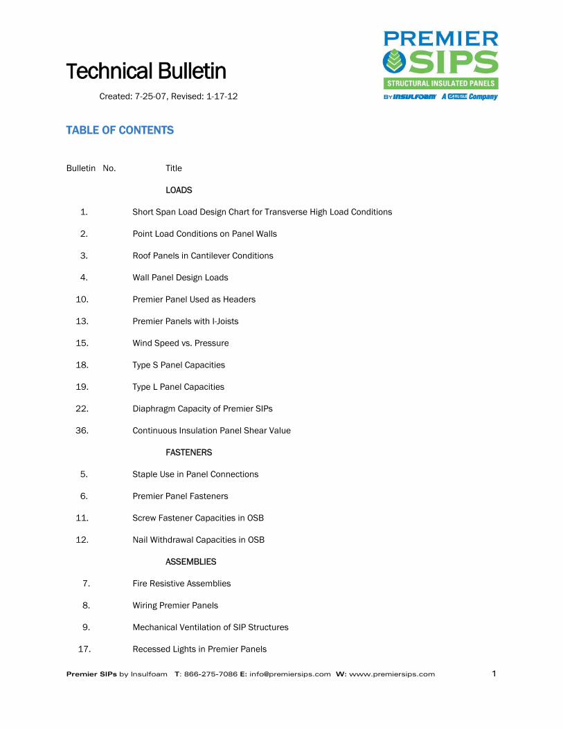
POINT LOAD CONDITIONS ON PANEL WALLS Premier SIPs panel products are being used in many types of structures as a structural wall. In this
application, it is essential to understand the axial capacities of the panel wall and how the load is transferred
into a wall panel. In structures where a panel roof system is transferring the roof load to the wall panel, the
load transfer is continuous over the length of the wall. Axial capacities found in our load design charts can be
utilized as the maximum design loads. However, there are many applications where the load being transferred
into a wall panel from the roof or a floor is accomplished through a structural component such as a truss or a
beam, which places a point load on the wall panel. Premier Building Systems has conducted full-scale
destructive tests at an independent code recognized laboratory to determine the point load capacities for our
panel products.
When conducting the tests, it was determined that one of the worst case scenarios the wall panels are
subjected to is 2x trusses transferring loads through the narrow edge of the 2x chord onto a 3.5” core panel.
Following our typical detail for wall panel installation, a series of tests were conducted to determine the point
load capacity of a standard panel. The data from these tests is shown in the chart below. Once values were
determined for a standard panel a second series of tests were conducted by the independent laboratory on a
standard 3.5” wall that had an additional plate fastened to the top of the panels. This plate can be either
standard 2x SPF lumber, 1-1/8” OSB(Oriented Strand Board) or 1-1/8” OSL(Oriented Strand Lumber) i.e.
Rimboard, which has been ripped to the overall width of the wall panel so that the OSB skins of the panel are
covered by the ripped material. Placement of this additional top plate substantially increases the point load
capacity of a panel. The results are shown in the table below.
To calculate the point load that a member will be placing on a panel, it is necessary to take into account the
intended live and dead loads and the tributary area that the member is designed to carry. An example would
be the placement of roof trusses 2’ o.c. which are spanning 60’ with only the exterior panel walls as support
and the trusses extending 2’ beyond the wall for the roof overhang. For this example, let’s assume that the live
load for the roof is 35 psf and the dead load is 10 psf. In this situation, each truss is placing a point load on
the panel wall of 2880 pounds which is in excess of the design point load allowed for standard detailed panels.
However, if an additional top plate is used, the loading is acceptable. Another example would be the same roof
with a bearing wall running down the center of the structure. In this scenario the panel walls are subjected to a
point load of 1530 pounds which falls within the design capacity for a standard detailed panel wall.
Point Load Design Values 1 ½ “ Minimum Bearing 3” Minimum Bearing
Standard Detail 2040 lbs 2450 lbs Additional Top Plate 4030 lbs 4678 lbs
Design loads reflect the ultimate load divided by a safety factor of three (3). Loads in excess of the above values require posts under the point load. Posts to be designed by an engineer.

Technical Bulletin #3c
Created: 7-23-98, Revised: 6-14-11
Premier SIPs by Insulfoam T: 866-275-7086 E: [email protected] W: www.premiersips.com 1
ROOF PANELS IN CANTILEVER CONDITIONS Structural Insulated Panels produced by Premier SIPs are used in many applications in which the panel creates
the eave and gable end overhangs on a roof. The use of panels to create the overhangs is advantageous
because it speeds the construction of the project and saves labor costs associated with hand framing. Some
areas of the country use relatively small eaves while other portions of the country prefer larger overhangs.
Premier SIPs has had their structural insulated panels evaluated through a series of full scale destructive tests
at an independent code recognized laboratory to determine the capabilities of Premier SIPs in cantilever
applications. These full scale tests followed ASTM E-72 parameters for loading and monitoring deflection of
the tested panels. The following addresses the capabilities of Premier SIPs when installed in a cantilever
application for roof overhangs.
When evaluating overhangs or cantilevers consideration must be given as to how the panel is to be used on
the roof. The two applications that are possible include having the panel span parallel to the support wall
(FIGURE 1 and FIGURE 3) and having the panel span perpendicular to the support wall (FIGURE 2). Panels
installed perpendicular to the support wall are capable of supporting greater overhangs.
Premier SIPs used to create overhangs on gable end walls or on eave applications where the panel is parallel
to the support wall can be used up to 2’ in unsupported overhangs (FIGURE 1). Panels used parallel to the
support wall can support loads indicated in the “Cantilevered Roof Panels Parallel to Support Wall – Type “S”
Panel Capacity” load chart shown below.
Applications that allow for 8’ panel widths may have overhangs of up to 4’ when applied parallel as described
above (FIGURE 3). Four-foot overhangs of this type have load capacities equal to the loads indicated in the
“Cantilevered Roof Panels Parallel to Support Wall – Type “S” Panel Capacity” load chart shown below.

Technical Bulletin #3c
Created: 7-23-98, Revised: 6-14-11
Premier SIPs by Insulfoam T: 866-275-7086 E: [email protected] W: www.premiersips.com 2
Standard splined or Type S Panels (detail PBS-005) that are perpendicular to the support wall are capable of
supporting 4’ horizontal span overhangs provided the panel extends back onto the roof a minimum of twice the
distance of the overhang span.
In situations where increased loads are required or where an overhang greater than 4’ is desired, Premier SIPs
that utilize double 2x’s or wood I-beams as the spline mechanism (PBS-006 or PBS-007) can be used. These
applications are created when the panels are perpendicular to the support wall and the panels extend back on
to the roof to a support, a minimum distance of twice the length of the overhang. When the double 2x or wood
I-beams are used at a frequency of 4’o.c., as the attachment spline between panels, overhangs of up to 6’ can
be achieved.
Greater loads can be achieved if the double 2x’s or wood I-beams are used at a frequency of 2’o.c. Overhangs
of up to 6’ feet of horizontal projection are possible. As stated earlier, the panel assembly must extend back
onto the roof, to a support, at a minimum twice the intended overhang horizontal span.
Refer to the load chart “Cantilevered Roof Panels Perpendicular to Support Wall (Figure 2) Panel Capacity”,
shown below, for load capacities of cantilevered roof panels in these cases.
Cantilevered Roof Panels Parallel to Support Wall – Type “S” Panel Capacity (psf)
Panel Core Thickness
Figure 1 Figure 2 2’ Maximum
Cantilever 4’ Maximum Canti-
lever 3 ½” 81* 41* 5 ½” 114* 57* 7 ¼” 149* 75* 9 ¼” 161* 81*
11 1/4 166* 83* * Value is less than the ultimate load divided by a safety factor of three.
Cantilevered Roof Panels Perpendicular to Support Wall (Figure 2) Panel Capacity (psf)
Panel Core Thickness
Type “S” Panel Type “L” or “I” Panels with Splines 4’ o.c.
Type “L” or “I” Panels with Splines 2’ o.c.
4’ cantilever with minimum 8’ back
span
4’ cantilever with minimum 8’ back span
6’ cantilever with minimum 12’ back span
4’ cantilever with minimum 8’ back span
6’ cantilever with minimum 12’ back span
3 ½” 41* 53* 54* 81* 53* 5 ½” 57* 87* 67* 114* 87* 7 ¼” 75* 115* 84* 149* 115* 9 ¼” 81* 125* 91* 161* 125*
11 ¼” 83* 129* 93* 166* 129* * Value is less than the ultimate load divided by a safety factor of three.

Technical Bulletin #4b
Created: 8-6-98, Revised: 6-14-11
Premier SIPs by Insulfoam T: 866-275-7086 E: [email protected] W: www.premiersips.com 1
WALL PANEL DESIGN LOADS
Building materials that are utilized to create structural components such as walls are subject to a combination
of loads. Wall assemblies must be able to withstand axial forces, while at the same time resisting a bending
load. Most building materials including concrete, steel lumber and other engineered wood products determine
their acceptability for application, in an assembly, through the use of a well-known engineering formula known
as the Unity Equation.
The Unity Equation takes into account the ultimate load capacity for a product in both the axial and transverse
directions. These ultimate loads are divided by a factor of safety which yields design values. In determining if
a product is acceptable for use, the product must meet the following formula:
fa (Design Axial Load) fb (Design Bending Load) Fa (Allowable Axial Load) + Fb (Allowable Bending Load < 1
Premier SIPs have under gone extensive testing that allows design professionals to utilize this engineering
formula in their work with Premier SIPs. Premier SIPs has the necessary data through full scale destructive
testing at independent code recognized laboratories. Attached is a compilation of this data in the form of a
Load Design Chart. The chart has been put together with the design axial load listed on top and the design
transverse load beneath..

Technical Bulletin #4b
Created: 8-6-98, Revised: 6-14-11
Premier SIPs by Insulfoam T: 866-275-7086 E: [email protected] W: www.premiersips.com 2
WALL PANEL ALLOWABLE DESIGN LOADS TYPE S Panels
Panel Core 8’ 10’ 12’ 16’ 20’ 24’
3 ½”
Axial Load
plf 3500 2553 2452 2118 N/A N/A
Trans Load psf
61 57 45 21 N/A N/A
5 ½”
Axial Load
plf 4250 4042 3373 3358 2817 N/A
Trans Load psf
80 60 46 34 21 N/A
7 ¼”
Axial Load
plf 4917 4325 4473 4194 3496 3067
Trans Load psf
85 75 69 50 31 24
9 ¼”
Axial Load
plf 4200 4200 4200 4200 3389 3247
Trans Load psf
86 65 57 46 39 34
11 ¼”
Axial Load
plf 3890 3890 3890 3890 3890 3333
Trans Load psf
94 76 59 51 39 33
Axial loads represent ultimate divided by a safety factor of 3. Transverse loads are less than or equal to L/180 deflection or ultimate load divided by a safety factor of 3.
Loads do not reflect secondary effect of P∆.

Technical Bulletin #4b
Created: 8-6-98, Revised: 6-14-11
Premier SIPs by Insulfoam T: 866-275-7086 E: [email protected] W: www.premiersips.com 3
WALL PANEL ALLOWABLE DESIGN LOADS TYPE L Panels
Panel Core 8’ 10’ 12’ 16’ 20’ 24’
3 ½”
Axial Load
plf 4723 3903 3094 2350 N/A N/A
Trans Load psf
91 61 45 23 N/A N/A
5 ½”
Axial Load
plf 5849 5889 4278 4311 2933 N/A
Trans Load psf
182 112 80 49 29 N/A
7 ¼”
Axial Load
plf 6850 6111 5556 5181 4835 4082
Trans Load psf
188 133 117 80 44 24
9 ¼”
Axial Load
plf 5470 5470 5470 5470 5470 4250
Trans Load psf
188 147 134 108 68 53
11 ¼”
Axial Load
plf 4500 4333 4167 3750 3750 3333
Trans Load psf
188 167 153 110 83 70
Axial loads represent ultimate divided by a safety factor of 3. Transverse loads are less than or equal to L/180 deflection or ultimate load divided by a safety factor of 3. Loads do not reflect secondary effect of P∆. 2x’s are spaced at 4’ on center.
Technical Bulletin #5b
Created: 10-2-98, Revised: 6-14-11
Premier SIPs by Insulfoam T: 866-275-7086 E: [email protected] W: www.premiersips.com 1
STAPLE USE IN PANEL CONNECTIONS
Premier SIPs typically use 8d nails at 6” on center for the connection of splines and plates as shown in the
typical details. Many contractors prefer to use staples as the typical fastener for their projects. Staples maybe
used instead of 8d nails provided they meet the following criteria:
Minimum Staple Length = 1- ½”
14 gauge - 6” on center.
16 gauge - 4” on center.
Chisel point staples are preferred
The suggested size and spacing for the staples is an equivalent to the typical 8d nails. Each project should be
reviewed to make sure that the minimum nailing patterns satisfy design conditions. High diaphragm loads may
require more fasteners depending on the diaphragm design loads.
Staples are not recommended for use in SIP shear walls in seismic design categories D, E and F.
Technical Bulletin #6c
Created: 10-7-98, Revised: 6-14-11
Premier SIPs by Insulfoam T: 866-275-7086 E: [email protected] W: www.premiersips.com 1
PREMIER PANEL FASTENERS
Premier SIPs has completed the development of a panel fastener. This fastener was developed specifically, for
the attachment of Premier SIPs to beams, purlins and posts made of wood and soft iron. Premier SIPs panel
fastener uses state of the art tempering and coating technology to create a #14 screw that drives easily into
wood, engineered woods and soft steel without bending, breaking or stripping out the multi-lobed head. The
screw is corrosion resist and passes more than 15 cycles in the industry standard “Kesternich cabinet”.
The screw has been designed with an aggressive thread pattern that demonstrates excellent pull out
resistance. In independent code recognized laboratory testing, Premier SIPs panel fasteners exhibited 980
pounds of pull-out resistance when installed 1” into a typical SPF#2 2 x 4. The laboratory also checked the
screw for resistance to shear. The test was designed to simulate a worst case scenario where a 14” Premier
SIPs panel fastener was driven through a 12”thick panel and into SPF#2 dimensional lumber. The fastener
withstood over 830 pounds of force without shearing. The failure mode was the screw head pulling through
the OSB. The design of the screw head provides a pull-through capacity of 735 pounds. These values are the
tested ultimate capacities.
The use of the Premier SIPs panel fastener is specified in the Premier SIPs typical details. Wall connections
require that screws be utilized 2’ on center. The frequency of panel fasteners required to anchor roof panels is
dependent on the imposed loads the panels must resist and the number of attachment points available. See
the Premier SIPs typical details for recommendations and follow the requirements specified on the shop
drawings.
The Premier SIPs panel fastener can be used in light gauge steel framing up to ¼” thick. Different points are
used on the Premier SIPs panel fasteners that are used in these light gauge steel applications, so you will want
to check with your Premier SIPs representative for the requirements of your specific project.
Technical Bulletin #7b
Created: 10-7-98, Revised: 6-14-11
Premier SIPs by Insulfoam T: 866-275-7086 E: [email protected] W: www.premiersips.com 1
FIRE RESISTIVE ASSEMBLIES
Premier SIPs has conducted the most extensive fire assembly testing in the SIP Industry. As a result of this
destructive testing, we can document the performance of Premier SIPs under the rigorous test standards of
ASTM – E119, ASTM - E84 and UBC 26-3. One Hour fire resistive assemblies are achieved by combinations of
underlying structure and protection of that structure by Gypsum Wall Board.
Residential structures are typically required to meet a fifteen minute standard. That standard is commonly met
by applying ½” layer of gypsum drywall over Premier SIPs panels.
Commercial and multi-family structures can be required to meet one-hour fire resistive standards. These
prescriptive assemblies are listed in the UL Fire Resistive Assembly Book, but can be summarized as follows;
1.) Two layers of 5/8" Type X gypsum, attached per Premier SIPs code report, over Premier SIPs
panels with either spline or lumber connections.
2.) One layer of 5/8" Type C gypsum, attached per Premier SIPs code report, over Premier SIPs panels
joined with dimensional lumber or solid engineered wood products.
As with any fire resistive issue, the local jurisdiction requirements will vary by region. You should contact your
local building department to determine requirements and involve the Premier SIPs Sales and Technical team
early in the design process in order to satisfy any concerns by either the building department or the design
professional.
Technical Bulletin #8b
Created: 10-1-98, Revised: 6-14-11
Premier SIPs by Insulfoam T: 866-275-7086 E: [email protected] W: www.premiersips.com 1
WIRING PREMIER SIPs
The Structural Insulated Panels manufactured by Premier SIPs are both simple and easy for electricians to
wire. It does require a small amount of advance planning. 1-½” diameter wiring chases are provided in the
panel cores for quick access by the electricians. The chases are typically located at 16" and 45” off the
finished floor as well as vertically 4' on center. These locations as well as any custom chases should be
verified during the shop drawing phase.
Type NM-B cable, as labeled by Underwriters Laboratories, passes UL-719 that mandates a maximum
conductor temperature of 9000C (19400F). The conductor temperatures under normal loads will not exceed
6000C, due to the restrictions on amperage loading and breaker sensitivity.
The wiring used for most residential and light commercial structures, commonly referred to as “Romex”, is
widely available with the NM-B designation labeled by UL and is acceptable for use with Premier SIPs.
Technical Bulletin #9b
Created: 10-2-98, Revised: 6-15-11
Premier SIPs by Insulfoam T: 866-275-7086 E: [email protected] W: www.premiersips.com 1
MECHANICAL VENTILATION OF SIP STRUCTURES
As we insulate and seal homes to achieve greater levels of comfort and energy independence, Premier SIPs
have proven themselves to be the most cost effective and stable method of construction. Although this
simplified process of super-insulation has shown positive impacts on the quality, comfort and energy savings of
structures, it has also created the need for controlled ventilation. Many of today's indoor airborne pollutants
can be effectively controlled, and ultimately increase the comfort and livability of a structure.
Mechanical ventilation has proven effective in mitigating fumes from combustion appliances, radon,
formaldehyde and even pollutants such as excess humidity and tobacco smoke. Established levels of humidity
are governed by region. A rough rule of thumb is to limit the relative humidity, in the interior of a building, to
50% or less. This will be low enough to inhibit mold or mildew based pollutants yet high enough to reduce low
humidity pollutants like dust mites.
In order to remove the contaminated air, a means of exhaust is essential. Typically, that exhausted air is
replaced with fresh air from outside the structure. Several methods of accomplishing this are available. They
are listed as follows:
1.) Air to air heat exchangers - These small units generally draw air from source areas like
kitchens and bathrooms where excess humidity is created. Moisture laden warm air is carried through
ducts to the unit where it transfers the heat through a core, similar in function to the radiator of a car,
while carrying the moisture out of the structure. Thus, the exhaust air tempers or pre-heats the cold
unconditioned but fresh air that is coming in from outside. These units are also known as HRV's or
Heat Recovery Ventilators.
2.) Exhaust only systems - These units come in many shapes and sizes from, simple one room
units to multiple duct whole house exhausts. This type of unit typically exhausts the stale air and
relies upon natural infiltration to replace the exhausted air. Exhaust only systems can create a
negative pressure in the structure.
3.) Ventilating windows - These windows use a small grille to both exhaust and replace air in a
house. They are manually operated and can be used in selected windows or in every window in a
home.
4.) Air Cleaners - These units run the gamut from inexpensive table top versions to very
sophisticated whole house systems. They are used to remove particulate pollutants but generally are
not designed for the removal of gaseous pollutants. Typically these are not recommended for either
humidity or radon control.
Whatever your choice in mechanical ventilation, your design professional should be involved in any indoor air
quality maintenance design. Several sources are available for in depth, objective, information on the subject of
air quality.
Some are listed below:

Technical Bulletin #9b
Created: 10-2-98, Revised: 6-15-11
Premier SIPs by Insulfoam T: 866-275-7086 E: [email protected] W: www.premiersips.com 2
National Center for Appropriate Technology
P.O. Box 2525 Butte, MT 59702-2525 (800) 428-2525
Energy Efficiency and Renewable Energy Clearinghouse
P.O. Box 3048 Merrifield, VA 22116 (800) DOE-EREC

Technical Bulletin #10c
Created: 10-7-98, Revised: 6-15-11
Premier SIPs by Insulfoam T: 866-275-7086 E: [email protected] W: www.premiersips.com 1
PREMIER PANEL USED AS HEADERS
When erecting structures that utilize Premier SIPs for the wall assemblies, several options are available to the
contractor when a window, door or other opening requires a load to be carried over the opening. Typically, a
situation of this type requires a header. Premier SIPs allow the contractor several options that include,
Premier’s Insulbeam II, using the panel as a header, or the use of conventional materials for the header.
Premier’s Insulbeam II and the use of the panel as a header are best suited for panel applications since both
provide insulation in the header area.
When a header is used, the load carrying capacity of the header must be established and determined
acceptable for the intended application. Refer to Premier SIPs load charts for the necessary design
information required so a designer, engineer or contractor may determine whether a panel can be used as a
header. Current load charts maybe found at www.premiersips.com.
In cases where a concentrated load is placed over an opening or the design loads exceed the capacity of the
panel header, Premier’s Insulbeam II should be used. If these header options do not work, other engineered
header assemblies will need to be considered.
Technical Bulletin #11b
Created: 12-13-98, Revised: 6-15-11
Premier SIPs by Insulfoam T: 866-275-7086 E: [email protected] W: www.premiersips.com 1
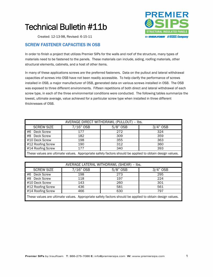
SCREW FASTENER CAPACITIES IN OSB
In order to finish a project that utilizes Premier SIPs for the walls and roof of the structure, many types of
materials need to be fastened to the panels. These materials can include, siding, roofing materials, other
structural elements, cabinets, and a host of other items.
In many of these applications screws are the preferred fasteners. Data on the pullout and lateral withdrawal
capacities of screws into OSB have not been readily accessible. To help clarify the performance of screws
installed in OSB, a major manufacturer of OSB, generated data on various screws installed in OSB. The OSB
was exposed to three different environments. Fifteen repetitions of both direct and lateral withdrawal of each
screw type, in each of the three environmental conditions were conducted. The following tables summarize the
lowest, ultimate average, value achieved for a particular screw type when installed in three different
thicknesses of OSB.
AVERAGE DIRECT WITHDRAWL (PULLOUT) – lbs. SCREW SIZE 7/16” OSB 5/8” OSB 3/4” OSB
#6 Deck Screw 177 272 324 #8 Deck Screw 182 309 359 #10 Deck Screw 198 355 363 #12 Roofing Screw 190 312 360 #14 Roofing Screw 177 340 393 These values are ultimate values. Appropriate safety factors should be applied to obtain design values.
AVERAGE LATERAL WITHDRAWL (SHEAR) – lbs.
SCREW SIZE 7/16” OSB 5/8” OSB 3/4” OSB #6 Deck Screw 198 273 295 #8 Deck Screw 118 197 224 #10 Deck Screw 143 260 301 #12 Roofing Screw 436 581 561 #14 Roofing Screw 466 630 797
These values are ultimate values. Appropriate safety factors should be applied to obtain design values.
Technical Bulletin #12b
Created: 12-18-98, Revised: 6-15-11
Premier SIPs by Insulfoam T: 866-275-7086 E: [email protected] W: www.premiersips.com 1
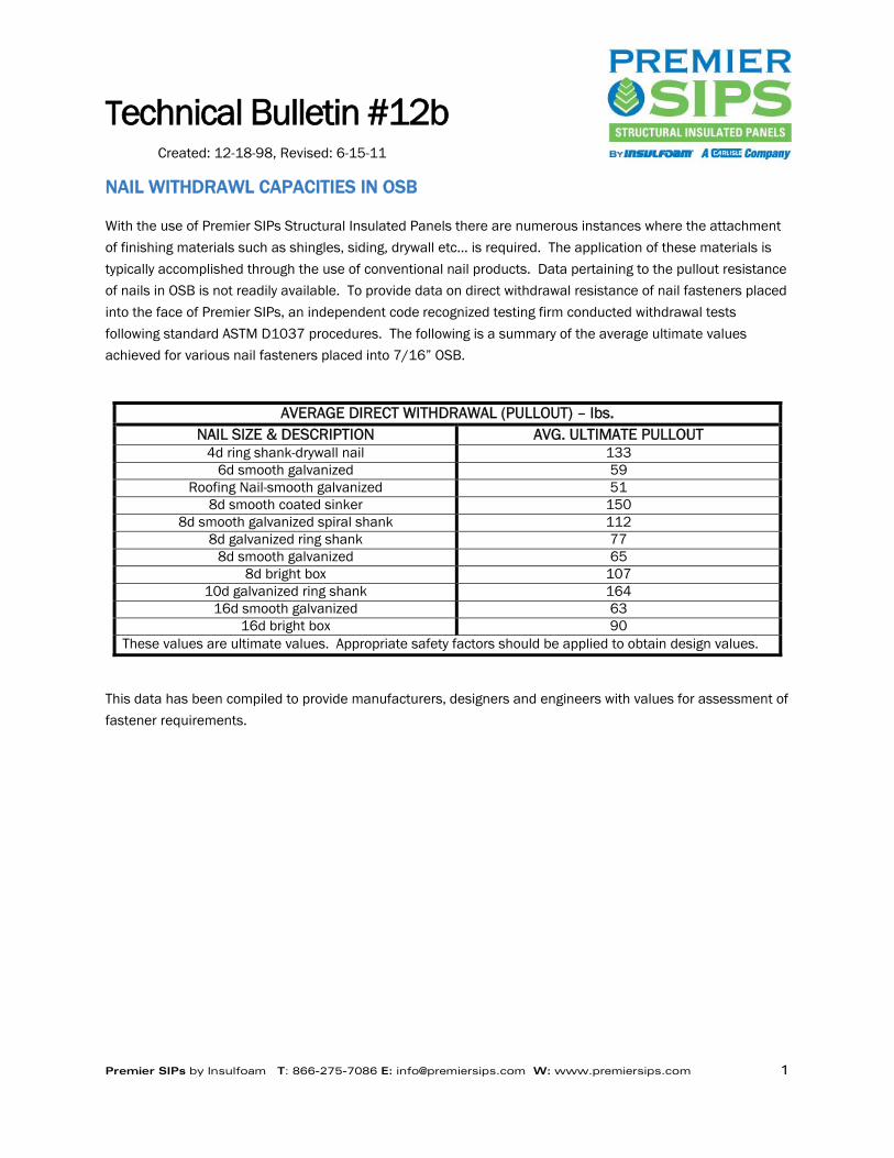
NAIL WITHDRAWL CAPACITIES IN OSB
With the use of Premier SIPs Structural Insulated Panels there are numerous instances where the attachment
of finishing materials such as shingles, siding, drywall etc… is required. The application of these materials is
typically accomplished through the use of conventional nail products. Data pertaining to the pullout resistance
of nails in OSB is not readily available. To provide data on direct withdrawal resistance of nail fasteners placed
into the face of Premier SIPs, an independent code recognized testing firm conducted withdrawal tests
following standard ASTM D1037 procedures. The following is a summary of the average ultimate values
achieved for various nail fasteners placed into 7/16” OSB.
AVERAGE DIRECT WITHDRAWAL (PULLOUT) – lbs.
NAIL SIZE & DESCRIPTION AVG. ULTIMATE PULLOUT 4d ring shank-drywall nail 133
6d smooth galvanized 59 Roofing Nail-smooth galvanized 51
8d smooth coated sinker 150 8d smooth galvanized spiral shank 112
8d galvanized ring shank 77 8d smooth galvanized 65
8d bright box 107 10d galvanized ring shank 164
16d smooth galvanized 63 16d bright box 90
These values are ultimate values. Appropriate safety factors should be applied to obtain design values.
This data has been compiled to provide manufacturers, designers and engineers with values for assessment of
fastener requirements.
Technical Bulletin #13c
Created: 3-10-99, Revised: 6-15-11
Premier SIPs by Insulfoam T: 866-275-7086 E: [email protected] W: www.premiersips.com 1
PREMIER PANELS WITH I-JOIST’S
In an effort to offer our customers the optimum in energy efficiency, Premier SIPs utilize APA rated I-Joists as
an interconnecting spline within our structural insulated panels. Utilizing the I-Joist spline minimizes the
thermal short circuiting that may occur with other types of spline options. Premier SIPs has conducted full-
scale destructive transverse load testing with an independent code recognized testing laboratory to determine
the capacity of our Type I panels for various spans.
The Type I load chart summarizes the panel capacities obtained from full scale destructive testing of Premier
SIPs Type I panels. It should be noted that when an I-Joist is used as a spline member it is spaced at a
maximum of 4’ on center and extends the full length of the panel. See PBS detail PBS-309, in the Premier
SIPs typical details. The minimum bearing required to support the panel ends is 1-½”. In the case of a single
span roof panel, spanning from the ridge to the eave, the 2x blocking at the top and bottom of the panel will
not be continuous because the I-Joist extends to the panel edges.
Current load charts maybe found at www.premiersips.com.
Technical Bulletin #14d
Created: 3-10-99, Revised: 10-4-11
Premier SIPs by Insulfoam T: 866-275-7086 E: [email protected] W: www.premiersips.com 1
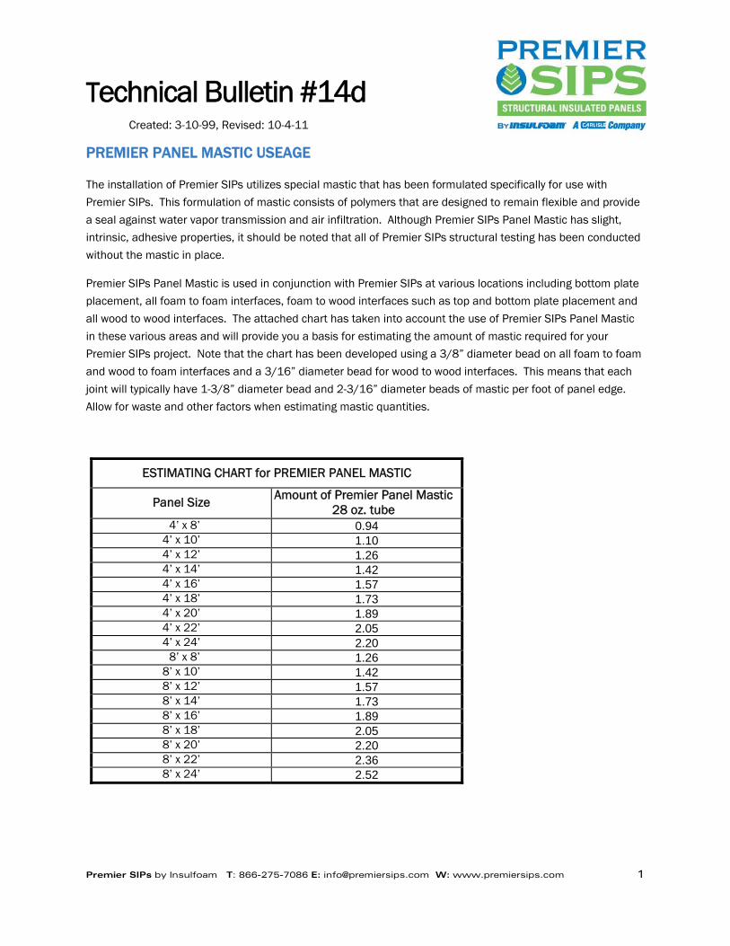
PREMIER PANEL MASTIC USEAGE
The installation of Premier SIPs utilizes special mastic that has been formulated specifically for use with
Premier SIPs. This formulation of mastic consists of polymers that are designed to remain flexible and provide
a seal against water vapor transmission and air infiltration. Although Premier SIPs Panel Mastic has slight,
intrinsic, adhesive properties, it should be noted that all of Premier SIPs structural testing has been conducted
without the mastic in place.
Premier SIPs Panel Mastic is used in conjunction with Premier SIPs at various locations including bottom plate
placement, all foam to foam interfaces, foam to wood interfaces such as top and bottom plate placement and
all wood to wood interfaces. The attached chart has taken into account the use of Premier SIPs Panel Mastic
in these various areas and will provide you a basis for estimating the amount of mastic required for your
Premier SIPs project. Note that the chart has been developed using a 3/8” diameter bead on all foam to foam
and wood to foam interfaces and a 3/16” diameter bead for wood to wood interfaces. This means that each
joint will typically have 1-3/8” diameter bead and 2-3/16” diameter beads of mastic per foot of panel edge.
Allow for waste and other factors when estimating mastic quantities.
ESTIMATING CHART for PREMIER PANEL MASTIC
Panel Size Amount of Premier Panel Mastic 28 oz. tube
4’ x 8’ 0.94 4’ x 10’ 1.10 4’ x 12’ 1.26 4’ x 14’ 1.42 4’ x 16’ 1.57 4’ x 18’ 1.73 4’ x 20’ 1.89 4’ x 22’ 2.05 4’ x 24’ 2.20
8’ x 8’ 1.26 8’ x 10’ 1.42 8’ x 12’ 1.57 8’ x 14’ 1.73 8’ x 16’ 1.89 8’ x 18’ 2.05 8’ x 20’ 2.20 8’ x 22’ 2.36 8’ x 24’ 2.52
Technical Bulletin #15c
Created: 3-17-99, Revised: 6-15-11
Premier SIPs by Insulfoam T: 866-275-7086 E: [email protected] W: www.premiersips.com 1
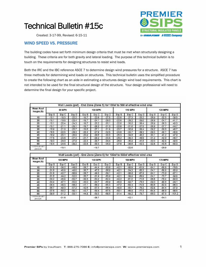
WIND SPEED VS. PRESSURE
The building codes have set forth minimum design criteria that must be met when structurally designing a
building. These criteria are for both gravity and lateral loading. The purpose of this technical bulletin is to
touch on the requirements for designing structures to resist wind loads.
Both the IRC and the IBC reference ASCE 7 to determine design wind pressures for a structure. ASCE 7 has
three methods for determining wind loads on structures. This technical bulletin uses the simplified procedure
to create the following chart as an aide in estimating a structures design wind load requirements. This chart is
not intended to be used for the final structural design of the structure. Your design professional will need to
determine the final design for your specific project.
Technical Bulletin #16c
Created: 3-17-99, Revised: 6-15-11
Premier SIPs by Insulfoam T: 866-275-7086 E: [email protected] W: www.premiersips.com 1
PREMIER SIPs & OFF-GASSING
Premier SIPs Structural Insulated Panels have been used in numerous applications where chemical sensitivity
is a consideration. A common question that was asked in these application was “Do the panels emit any
harmful gases such as formaldehyde?”
In an effort to definitively answer this question, Premier SIPs contracted with an independent, accredited
testing laboratory to conduct formaldehyde testing. ASTM E1333, “Standard Test Method for Determining
Formaldehyde Concentrations in Air and Emissions Rates from Wood Products Using a Large Chamber,
Standard Face and Back Configuration” was conducted to determine, if in fact, any off gassing does occur.
This ASTM test procedure is designed to measure the formaldehyde concentration in air based on the emission
rate of newly manufactured products under conditions designed to simulate product use.
The sophisticated test equipment used to measure concentration levels in this test allow detection of
emissions down to .03 ppm (parts per million). The result of Premier SIPs in this rigorous test for the
formaldehyde concentration in the test chamber was “Below Minimum Detectable Level”.
This full scale testing of Premier SIPs demonstrates that Premier SIPs do not emit detectable amounts of
formaldehyde.
One must realize that formaldehyde is found in nature and around us, all the time. Plywood and OSB are not
going to cause most people any sensitivity problems. Major sources of formaldehyde typically found in the
home are from particle board or pressed wood used in furniture, cabinets and shelving and carpeting.
Chemically sensitive individuals have occupied homes utilizing Premier SIPs and have had no reactions what
so ever.
Technical Bulletin #17d
Created: 3-17-99, Revised: 6-2-14
Premier SIPs by Insulfoam T: 866-275-7086 E: [email protected] W: www.premiersips.com 1
RECESSED LIGHTS IN PREMIER SIPs
Premier SIPs are frequently used in vaulted roof/ceiling applications. While the panels provide an excellent
method to create a vaulted ceiling, there are limitations on the types of lighting that can be utilized with our
panels. The biggest limitation is for recessed or can lights that are intended to be recessed into the finished
ceiling and create a flush finish.
Premier SIPs has researched the application of recessed light fixtures and has determined that the application
of these type lights into our roof panels could cause problems. These potential problems stem from the heat
created by these fixtures and the reduction of panel insulation, which may lead to condensation issues.
Premier SIPs recommends that track lighting or some other type of surface mounted lighting be used in lieu of
recessed fixtures when Premier SIPs make up the roof/ceiling assembly.
An economical option that should be considered, in lieu of the recessed can light, is a surface mounted LED
light. This type of light is easily surface mounted in a junction box with just 2.5 inches of depth. The trim
pieces provide attractive finishes that hide the low profile junction box.
If the options stated above have been eliminated as possible solutions on a given project, and it has been
determined by the design professional, that the heat produced from the recessed lights and the reduced
amount of insulation in the SIPs will not cause any issues the Premier SIPs NTA listing report can be used as a
guide for placement of holes in roof panels for recessed lights. Refer to Technical Bulletin #37 for sealing
holes, penetrations and electrical chases in Premier SIPs.
Technical Bulletin #18c
Created: 3-30-99, Revised: 6-15-11
Premier SIPs by Insulfoam T: 866-275-7086 E: [email protected] W: www.premiersips.com 1
TYPE S PANEL CAPACITIES
In an effort to offer our customers the optimum in energy efficiency, Premier SIPs utilizes the Premier SIPs
spline as an interconnecting spline within our structural insulated panels. Utilizing the Premier SIPs spline
virtually eliminates the thermal short circuiting that may occur with other types of spline options. To determine
the capacities of Type S panels, Premier SIPs has conducted full-scale destructive transverse load testing with
a major university and an independent code recognized laboratory.
The Type S load chart summarizes the panel capacities obtained from full scale destructive testing of Premier
SIPs Type S panels. The minimum bearing that is required to support the panel end is 1-½”. Loads indicated
in the load chart for spans greater than limited for floors and roofs are used for wall design.
Current load charts maybe found at www.premiersips.com.
Technical Bulletin #19c
Created: 3-31-99, Revised: 6-15-11
Premier SIPs by Insulfoam T: 866-275-7086 E: [email protected] W: www.premiersips.com 1
TYPE L PANEL CAPACITIES
Premier SIPs utilizes Type L panels when the structural design loads exceed the capacities of our standard
Type S and Type I panels. Details PBS-308 and PBS-007, found in the typical details, depict the Type L panel
and connection. The double 2x’s used, as the spline mechanism, must extend the full length of the panel.
Premier SIPs has conducted full-scale destructive transverse load testing with an independent code recognized
testing laboratory to determine the capacity of our Type L panels for various spans.
The Type L load chart summarizes the panel capacities obtained from full scale destructive testing of Premier
SIPs Type L panels. When Type L panels are utilized, the maximum spacing of the lumber spline is 4’ on
center. The minimum bearing that is required to support the panel end is 1-½”. Loads indicated in the load
chart for spans greater than limited for floors and roofs are used for wall design.
Current load charts maybe found at www.premiersips.com.
Technical Bulletin #20b
Created: 4-8-99, Revised: 6-15-11
Premier SIPs by Insulfoam T: 866-275-7086 E: [email protected] W: www.premiersips.com 1
PREMIER SIPs SPLINES
Premier SIPs uses three types of splines for connecting its structural insulated panels. The three types of
splines are the Premier SIPs spline for our Type “S” panel, the I-Joist spline for our Type “I” panel and the
double 2x or dimensional lumber spline for our Type “L” panel. Each of these splines provides a minimum
width for fastening of 3”. These splines and the corresponding minimum width for fastening have been
determined with regard to the OSB manufacturers recommended edge fastening distances and what is
practical in actual on site conditions.
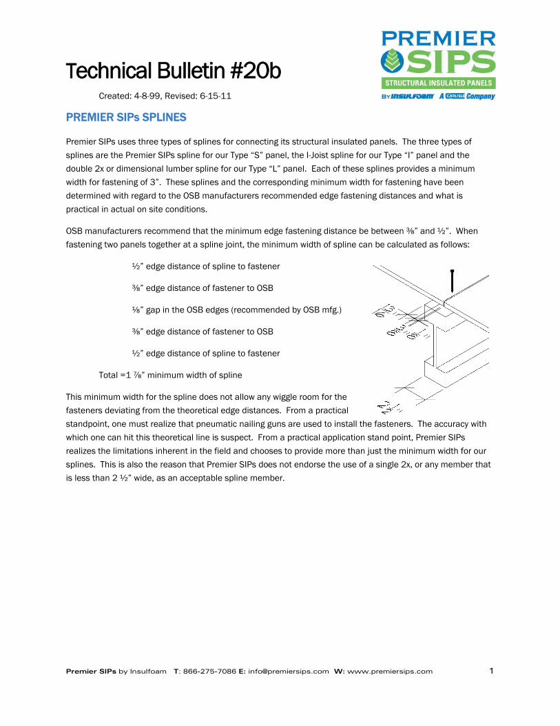
OSB manufacturers recommend that the minimum edge fastening distance be between ⅜” and ½”. When
fastening two panels together at a spline joint, the minimum width of spline can be calculated as follows:
½” edge distance of spline to fastener
⅜” edge distance of fastener to OSB
⅛” gap in the OSB edges (recommended by OSB mfg.)
⅜” edge distance of fastener to OSB
½” edge distance of spline to fastener
Total =1 ⅞” minimum width of spline
This minimum width for the spline does not allow any wiggle room for the
fasteners deviating from the theoretical edge distances. From a practical
standpoint, one must realize that pneumatic nailing guns are used to install the fasteners. The accuracy with
which one can hit this theoretical line is suspect. From a practical application stand point, Premier SIPs
realizes the limitations inherent in the field and chooses to provide more than just the minimum width for our
splines. This is also the reason that Premier SIPs does not endorse the use of a single 2x, or any member that
is less than 2 ½” wide, as an acceptable spline member.

Technical Bulletin #21b
Created: 4-8-99, Revised: 6-15-11
Premier SIPs by Insulfoam T: 866-275-7086 E: [email protected] W: www.premiersips.com 1
PREMIER SIPs PANELS USED IN FLOOR APPLICATIONS
Premier SIPs are often used in floor applications when an insulated floor system is required. Examples of this
situation are over a crawl space, the floor of a sun room addition or the bedroom floor over an unheated
garage.
When using Premier SIPs in floor applications, there are a few design considerations to keep in mind. Premier
SIPs recommends that the floor panel be overlaid with an additional layer of 7/16” sheathing. The reason for
this is that in most situations we use 7/16” OSB for the panel skins and we want to minimize puncturing of the
panel skins.
Floor panels are not able to support load bearing walls and the floor panels cannot be cantilevered over a
lower wall to support upper wall and roof systems.
The load limitations of the panels used in floor systems is covered by our load design charts and other
technical bulletins.
Technical Bulletin #22c
Created: 4-26-99, Revised: 6-15-11
Premier SIPs by Insulfoam T: 866-275-7086 E: [email protected] W: www.premiersips.com 1
DIAPHRAGM CAPACITY OF PREMIER SIPs
Premier SIPs has completed a series of full-scale diaphragm tests to determine design values for Premier SIPs
Structural Insulated Panels. These full-scale tests were conducted following the protocols of ASTM E455
“Standard Method for Static Load Testing of Framed Floor or Roof Diaphragm Constructions for Buildings” and
ASTM E1803 “Standard Test Methods for Structural Capacities of Insulated Panels”.
Three separate assemblies using variations of fasteners were tested in sets of two, as is required in the ASTM
protocols. Each diaphragm was made up of 6-4’x12’x6” panels creating a diaphragm of 8’ x 36’ for an aspect
ratio of 4.5 to1. The panels were supported on 4x6’s at each 8’ edge and at the third points along the 36’
length of the diaphragm. Along the 36’ lengths of the diaphragm were 4x6’s that were spliced together to act
as the chord members of the diaphragm. The two 8’ ends of the diaphragm were the support locations, which
simulated shear walls supporting the diaphragm.
The lateral loads were applied to the diaphragm at the third points via a hydraulic ram. The 4x6 frame had
reaction points at the end of each of the 8’ sides. By applying loads through the panel diaphragm in this
manner and having the reaction points on the 4x6 frame, we were assured that the load was applied to the
panel diaphragm; therefore, the screw fasteners had to transfer the shear forces to the supporting 4x6’s.
Each set of the three panel assemblies varied the number of screws and nails that were used to connect the
panels to each other and to the supporting 4x6’s. In two of the tests the fastening pattern within the
diaphragm varied according to the expected shear forces in the diaphragm. These two diaphragms were
sectioned into thirds. The center third of the diaphragm had less fasteners than the outside thirds as the loads
in this area are minimal. Fastener number and placement corresponded to the shear diagram of the tested
diaphragm, i.e. more fasteners at a closer spacing were used in the outside thirds of the diaphragms as
compared to the center third of the diaphragm. Shear is always the greatest at the supported edges. This was
done as a means to economize labor as well as the number of fasteners used in the diaphragm. All fasteners
installed in these tests were applied on the topside of the diaphragm only. Premier SIPs typical details call for
8d nails at the splines on both faces of the panel. When top spline only methods are used the fastening
frequency is doubled.
The first assembly used 8d nails @ 3” on center throughout the diaphragm to fasten the 7/16” OSB splines.
The 3” on center spacing was used because the diaphragm was only nailed on the topside. The typical nail
spacing is 6” on center for fastening splines on both faces of the panels. The panel screw fasteners were
spaced at 12” on center into all of the 4x6’s. This diaphragm achieved 450-plf design shear capacity. This
value reflects a safety factor of three. The deflection of the diaphragm across the 36’ at 435-plf was 0.41”.
The second assembly used 8d nails @ 3” on center to fasten the OSB splines in the center third of the
diaphragm and 2” on center in the outside thirds. The panel fastener spacing in the outside thirds of the
diaphragm was decreased to 3” on center. The screw spacing was changed for the end of the diaphragm as
well as along the top and bottom chords of the diaphragm. This diaphragm achieved 550-plf design shear
capacity. Again this value has a safety factor of three. The deflection of the diaphragm across the 36’ at 538-
plf was 0.37”.

Technical Bulletin #22c
Created: 4-26-99, Revised: 6-15-11
Premier SIPs by Insulfoam T: 866-275-7086 E: [email protected] W: www.premiersips.com 2
The third assembly used 8d nails @ 3” on center to fasten the OSB splines in the center third of the diaphragm
and 1 ½” on center in the outside thirds. The panel fastener spacing in the outside thirds of the diaphragm
was decreased to 2” on center. The screw spacing was changed for the end of the diaphragm as well as along
the top and bottom chords of the diaphragm. This diaphragm had a design value of 750-plf. This value
represents a safety factor of three. The deflection of the diaphragm across the 36’ at 750-plf was 0.37”.
Subsequent to the diaphragm testing just described, Premier SIPs conducted an additional two diaphragm
tests. In these tests the same nail and panel fastener spacing was maintained throughout the diaphragm,
which consisted of 6-4’x8’x6” panels configured to make an 8’x24’ diaphragm.
The first diaphragm utilized 7/16” splines connecting the panels with a nailing pattern of two rows of 0.113” x
2-3/8” nails at 3” on center. Only the top OSB skin was nailed. The perimeter panel fastener screws attaching
the diaphragm to the chord members were spaced at 4” on center. This diaphragm had a capacity of 917 plf.
The deflection of the diaphragm across the 24’ at 917-plf was 0.18”.
The second diaphragm utilized 23/32” splines connecting the panels with a nailing pattern of two rows of
0.113” x 2-3/8” nails at 3” on center. Only the top OSB skin was nailed. The perimeter panel fastener screws
attaching the diaphragm to the chord members were spaced at 4” on center. This diaphragm had a capacity of
1136 plf. The deflection of the diaphragm across the 24’ at 1136-plf was 0.19”.
Each of the values reported for the capacity of the diaphragm is a design value. It has a factor of safety of
three associated with it.
In any designs using the diaphragm capacity of the panels, it is up to the designer or engineer to determine the
required diaphragm capacities and then apply the values described in this technical bulletin appropriately.

Technical Bulletin #23b
Created: 12-4-99, Revised: 6-15-11
Premier SIPs by Insulfoam T: 866-275-7086 E: [email protected] W: www.premiersips.com 1
COMBUSTION TOXICITY OF PREMIER SIPs
Premier SIPs have undergone numerous fire tests for code recognition of our panels including ASTM E84
“Surface Burning Characteristics”, ASTM E119 “Hourly Testing” UL 1715 “Corner Room Burn” etc. Panels that
have been in real life fire scenarios have also shown that panels hold up well in these events. However, the
question regarding gasses that are produced during combustion still arises from time to time.
One must realize that when a material is burned, combustion gases are given off. In the case of Premier SIPs
the primary gases given off are carbon monoxide, carbon dioxide and water vapor. These gases are found in
many fires containing organic materials. These particular gases are around us all the time. In high
concentrations or in the absence of oxygen asphyxiation can occur.
In fires the materials that compose the interior of the structure i.e. carpet, furniture etc. are the primary threat
when considering toxic combustion gases. Premier SIPs, when burned, give off by products that are similar to
those found when wood is burned.
The building codes have evaluated Premier SIPs and the panels have been found to meet the building codes
criteria, which includes fire testing. In addition, our extensive fire testing allows Premier SIPs to carry the mark
of Underwriters Laboratories Inc.
Technical Bulletin #24b
Created: 1-12-00, Revised: 6-15-11
Premier SIPs by Insulfoam T: 866-275-7086 E: [email protected] W: www.premiersips.com 1
ATTACHMENT OF EXTERIOR CLADDINGS TO PREMIER SIPs
Premier SIPs are used in both commercial and residential applications. Through the years our panels have had
nearly every type of exterior cladding applied to the face of the panels. The advent of new exterior claddings in
the market place always brings the question of how the new product should be applied to the panel. This
bulletin is a review of common claddings that are available and their attachment to panels.
Most exterior claddings, currently available in the market place, make reference that their product should be
attached to the framing members of the structure. Premier SIPs do not incorporate framing members and
therefore do not meet their written recommendations. A review of the requirements for attachment of the
siding material typically calls out for the cladding to be attached with 8d nails 16” or 24” on center depending
on the framing spacing. Using these values one can compare the pullout values for 8d nails into standard
framing with the fastener pullout values listed in Technical Bulletins #11 and #12. This comparison shows
that all claddings with the requirements of fastening to framing members can be matched by applying 8d ring
shank nails 12”o.c.into Premier SIPs. This would include the attachment of standard sidings such as
hardboard, cedar, redwood, composites and cementations sidings.
This type of comparison is also valid for the application of lath for stucco as well as brick tie placement.
Typically, these products are attached to Premier SIPs by simply increasing the number of fasteners 25%.
When a manufacturer calls out for fasteners 16” o.c. the fasteners would be placed in a Premier SIPs panel at
a spacing of 12” o.c. This will allow the panel application to meet or exceed the pull out values required by the
siding manufacturer. It should be noted that the fastener placement can be maintained at the siding
manufacturer’s recommendations provided a nail/staple is replaced with a screw. In all cases the fastener
should be corrosion resistant.
Technical Bulletin #25c
Created: 5-1-03, Revised: 6-15-15
Premier SIPs by Insulfoam T: 866-275-7086 E: [email protected] W: www.premiersips.com 1
SOUND TRANSMISSION
Premier SIP panels have been erected in numerous residential and commercial applications where the
occupants have expressed great satisfaction with the reduced noise level within their structure due to the SIP
construction. While these stories are anecdotal they indicate that structures built with Premier SIP panels do
provide a measure of sound attenuation.
Within the building industry, specific tests are used to determine the Sound Transmission Class (STC) of an
assembly or component. ASTM E90 “Standard Test Method for Laboratory Measurement of Airborne Sound
Transmission Loss of Building Partitions and Elements”, subjects a wall assembly to random noises in a
frequency range of 125 Hz – 4000 Hz. The following are STC values for several Premier SIP panel assemblies
used in standard construction, which were determined through testing at an accredited independent
laboratory. These assemblies are for typical residential applications:
Premier SIP Panel (no finish either face) STC- 22 ½” gyp, Premier SIP Panel, no finish on other face STC- 28 5/8” gyp, Premier SIP Panel, no finish on other face STC- 29 5/8” gyp, Premier SIP Panel, 5/8” gyp STC- 33 2-layers 5/8” gyp, Premier SIP Panel, 2-layers 5/8” gyp STC- 41
Premier SIP panels are also used in town homes and condominiums. Hence, Premier SIPs has also conducted
ASTM E90 tests on wall assemblies that produce higher sound attenuation while meeting fire and clearance
requirements for these types of structures. These include:
Double Wall Assembly-A STC-45 5/8” gyp, Premier SIP panel, 5/8” gyp, 1” air space, 5/8”gyp, Premier SIPs panel, 5/8”gyp
Double Wall Assembly-B STC-47 2 layers 5/8” gyp, Premier SIP panel, 5/8” gyp, 1” air space, 5/8”gyp, Premier SIPs panel, 5/8”gyp
Double Wall Assembly-C STC-52 2 layers 5/8” gyp, Premier SIP panel, 5/8” gyp, 1” air space, 5/8”gyp, Premier SIPs panel, 2 layers 5/8”gyp
Double Wall Assembly-D STC-54 2 layers 5/8” gyp, Premier SIP panel, 2 layers 5/8” gyp, 1” air space, 5/8”gyp, Premier SIPs panel, 2 layers 5/8”gyp
In all of the above described cases, gypsum wallboard was attached using standard screws directly into the
face of the panel. In multiple layer applications the joints were offset a minimum of six inches from the joints
in the previous layer.
The following four assemblies use Premier SIP panels in conjunction with a proprietary patented clip assembly
to yield higher STC values that may be beneficial in certain conditions. The assemblies are as follows:
Assembly-1 STC-48 5/8” gyp, Premier SIP panel, proprietary clip assembly, fiberglass, 5/8”gyp
Assembly-2 STC-58
Technical Bulletin #25c
Created: 5-1-03, Revised: 6-15-15
Premier SIPs by Insulfoam T: 866-275-7086 E: [email protected] W: www.premiersips.com 2
2 layers 5/8” gyp, Premier SIP panel, proprietary clip assembly, fiberglass, 2 layers 5/8”gyp
Assembly-3 STC-52 5/8” gyp, Premier SIP panel, proprietary clip assembly, fiberglass, 5/8”gyp
Assembly-4 STC-59 2 layers 5/8” gyp, Premier SIP panel, proprietary clip assembly, fiberglass, 2 layers 5/8”gyp
Assemblies 1 through 4 used standard drywall screws to fasten the gypsum to either the SIP panel or the
proprietary clip assembly. In the multi layered assemblies the gypsum wall board joints were staggered
between layers.
The above results will be affected by the use of additional or different finish materials and are supplied as a
reference value. It should also be noted that sound attenuation is dependent on installation practices.
Penetrations through the wall assembly for electrical, plumbing and fenestration can affect the sound
transmission performance of a wall. Design consideration should be given to any penetrations through a wall
requiring a STC value.

Technical Bulletin #26b
Created: 5-29-03, Revised: 6-15-11
Premier SIPs by Insulfoam T: 866-275-7086 E: [email protected] W: www.premiersips.com 1
BEAM POCKETS IN PREMIER SIPs
Premier SIPs used in residential construction have had great success especially in the western United States.
A design that is favored in these locations calls for beams to be pocketed into the wall panel assembly. This
detail provides for an aesthetically pleasing interface between the wall and the support mechanism for roofs
and floors.
When this detail is used in conjunction with Premier SIPs the following points should be considered:
• Loads for the type of detail shown below are limited to the point loads established in the Premier SIPs
Design Manual. Basically this calls for a maximum design load of 2450 pounds for a standard 2x
plate used in the panel under the beam. The use of a cap plate does not allow for increased loads in
this application. When loads exceed 2450 pounds posting is required under the beam.
• This detail provides for a thermal short circuit in the wall panel system. Great care should be taken to
seal this joint. After sealants are placed in the pocket all interior interfaces must be further sealed
with Premier SIPs SIP Tape.
• Maximum design loads can be compromised if the beam pocket is over cut at the corner of the
pocket. Good craftsmanship is required to assure that the pocket is not over cut in the corners.
Technical Bulletin #27b
Created: 3-30-07, Revised: 6-15-11
Premier SIPs by Insulfoam T: 866-275-7086 E: [email protected] W: www.premiersips.com 1
VENTING OF PREMIER SIPs ROOF PANELS
Even though Premier SIPs have been used in unvented roof applications since the 1960’s, confusion still exists
about the need to vent Premier SIPs roof panels.
The building codes require ventilation of “enclosed attics and enclosed rafter spaces formed where ceilings are
applied directly to the underside of roof rafters.” The building code defines an attic as the unfinished space
between the ceiling joists of the top story and the roof rafters. When roof panels are used on a project an attic
space is not present because the panels are the exterior, insulated envelope of the structure. By definition, an
attic space does not exist.
The IRC Section R806.4 furthers the discussion by addressing “unvented conditioned attic assemblies (spaces
between the ceiling joists of the top story and the roof rafters)…” But, again, when panels are used on the roof,
an attic is not present. The interior space of the structure is all conditioned and usable.
To summarize, roof venting of Premier SIPs roof panels is not required. Refer to Premier SIPs Technical
Bulletin #9 for mechanical ventilation of SIP structures.
Technical Bulletin #28e
Created: 5-23-07, Revised: 7-27-12
Premier SIPs by Insulfoam T: 866-275-7086 E: [email protected] W: www.premiersips.com 1
VAPOR RETARDERS WITH PREMIER SIPs RESIDENTIAL PANELS
Questions about using vapor retarders in conjunction with Premier SIPs structural insulated floor, wall and roof
panels come up often. When installing Premier SIPs panels, Premier SIPs requires the proper application (as
shown in the Premier SIPs Typical Details) of panel mastic at all panel joints. The function of the mastic is to
provide a seal against water vapor transmission and air infiltration.
The purpose of this technical bulletin is to provide guidelines for the use of vapor retarders with Premier SIPs in
residential applications.
The International Residential Code (IRC) requires the following:
VAPOR RETARDERS
Class I or II vapor retarders are required on the interior side of frame walls in Climate Zones 5, 6, 7, 8
and Marine 4.
The definition of vapor retarder class from the IRC is:
VAPOR RETARDER CLASS. A measure of the ability of a material or assembly to limit the amount of
moisture that passes through that material or assembly. Vapor retarder class shall be defined using
the desiccant method with Procedure A of ASTM E 96 as follows:
Class I: 0.1 perm or less
Class II: 0.1 < perm ≤ 1.0 perm
Class III: 1.0 < perm ≤ 10 perm
The panels that Premier SIPs produces have a perm rating less than 1. Based on the IRC definition of vapor
retarder class, Premier SIPs meet the Class II definition. Panel joints are of concern with a SIP system when
considering vapor retarder application. Premier SIPs requires that panel mastic be used when joining panels.
Premier SIPs also recommends the use of SIP Tape over the panel joints. The SIP Tape is formulated with a
perm of less than 1. The combination of the Premier SIPs panels and the SIP Tape meets the building code
requirements for vapor retarders.
Typically, 6” wide SIP Tape is used at all wall and roof panel joints as well as at wall panel corners. The
connection of roof panels to exterior wall panels requires the use of 12” wide SIP Tape. Roof panels that have
joints on supporting beams require 18” wide SIP Tape. A ridge beam is an example of this condition.
The use of an additional vapor retarder, such as polyethylene sheeting, maybe warranted based on the local
building code and or climatic conditions. It is up to the design professional to make this determination. If an
additional vapor retarder is utilized, it must be installed properly.
Please refer to the Premier SIPs typical details for illustrations of these conditions. The typical details can be
requested by calling the number below, or it can be viewed online at www.premiersips.com.

Technical Bulletin #28d
Created: 5-23-07, Revised: 6-15-11
Premier SIPs by Insulfoam T: 866-275-7086 E: [email protected] W: www.premiersips.com 2
The use of an additional vapor retarder, such as polyethylene sheeting, maybe warranted based on the local
building code and or climatic conditions. It is up to the design professional to make this determination. If an
additional vapor retarder is utilized, it must be installed properly.
Please refer to the Premier SIPs typical details for illustrations of these conditions. The typical details can be
requested by calling the number below, or it can be viewed online at www.premiersips.com.
Technical Bulletin #29c
Created: 8-28-07, Revised: 6-16-11
Premier SIPs by Insulfoam T: 866-275-7086 E: [email protected] W: www.premiersips.com 1
PREMIER SIPs USED AS EXTERIOR WALLS
There are numerous opinions about which house wrap or felt, if any, to use on Premier SIPs wall panels. The
purpose of this technical bulletin is to provide guidelines for the use of materials over the exterior of Premier
SIPs wall panels.
Premier SIPs evaluation report states:
“The exterior face of wall panels are required to be covered with a wall covering, complying with the
applicable code or recognized in a current ICC-ES evaluation report. A water-resistive barrier must be
installed over the panels in accordance with IBC Section 1404.2, IRC Section R703,.2, BNBC Section
1406.3.6, and UBC Section 1402, as applicable, prior to application of the wall covering. Where
Portland cement plaster is used, compliance with IBC Sections 2510 and 2512, IRC Section R703.6.3
or UBC Section 2506.4, as applicable, is necessary. All exterior panel joints must be sealed with a
compatible acrylic latex caulk.”
Premier SIPs recommends that a water resistive barrier, as recognized by ICC-ES, be installed over Premier
SIPs used as exterior walls.
Current ICC-ES Report holders for water-resistive barriers can be obtained by visiting the ICC-ES website at
www.icc-es.org and navigating to Evaluation Reports, CSI List, Section 0728 – Water-Resistive Barriers.
The 2006 versions of the IRC and the IBC have the following requirements.
The 2006 International Residential Code (IRC) requires the following:
SECTION R703 – EXTERIOR COVERING
R703.1 General: Exterior walls shall provide the building with a weather-resistant exterior wall
envelope. The exterior wall envelope shall include flashing as described in Section R703.8.
The exterior wall envelope shall be designed and constructed in a manner that prevents the
accumulation of water within the wall assembly by providing a water-resistant barrier behind
the exterior veneer as required by Section R703.2 and a means of draining water that enters
the assembly to the exterior. ….
R703.2 Water-resistive barrier: One layer of No. 15 asphalt felt, free from holes and breaks,
complying with ASTM D226 for Type 1 felt or other approved water-resistive barrier shall be
applied over studs or sheathing of all exterior walls……
The 2006 International Building Code (IBC) requires the following:
SECTION 1403 – PERFORMANCE REQUIREMENTS
1403.2 Weather protection: Exterior walls shall provide the building with a weather-resistant
exterior wall envelope. The exterior wall envelope shall include flashing, as described in
Section 1405.3. The exterior wall envelope shall be designed and constructed in such a

Technical Bulletin #29c
Created: 8-28-07, Revised: 6-16-11
Premier SIPs by Insulfoam T: 866-275-7086 E: [email protected] W: www.premiersips.com 2
manner as to prevent the accumulation of water within the wall assembly by providing a
water-resistant barrier behind the exterior veneer, as described in Section 1404.2, and a
means for draining water that enters the assembly to the exterior. ….
1404.2 Water-resistive barrier: A minimum of one layer of No. 15 asphalt felt, complying with
ASTM D226 for Type 1 felt or other approved materials, shall be attached to the studs or
sheathing, with flashing as described in Section 1405.3, in such a manner as to provide a
continuous water-resistive barrier behind the exterior wall veneer.
The definition of a water-resistive barrier, from the IRC and the IBC is:
WATER-RESISTIVE BARRIER: A material behind an exterior wall covering that is intended to resist liquid
water that has penetrated behind the exterior covering from further intruding into the exterior wall
assembly.
Technical Bulletin #30b
Created: 11-9-07, Revised: 6-16-11
Premier SIPs by Insulfoam T: 866-275-7086 E: [email protected] W: www.premiersips.com 1
HEADERS IN PREMIER SIPs WALL PANELS
Premier SIPs Technical Bulletin #10 addresses the load carrying capacity of Premier SIPs used as headers and
refers to the Insul-Beam header. This Technical Bulletin focuses on how to support Insul-Beam headers as well
as headers constructed from an engineered wood product like LVL’s or built up headers constructed from
multiple plies of dimensional lumber.
Many design professionals and builders are familiar with how headers work in conventional framing when
considering load distribution around openings. Premier SIPs act differently than conventional stick framing
when load paths are considered. Premier SIPs wall panels, typically, do not use dimensional lumber in the
panels to transfer gravity loads. The OSB skins are the load transferring elements. It is for this reason that
Premier SIPs requires that the OSB skins of the wall panels be completely supported.
In situations where headers, other than Premier SIPs are used, the headers are sandwiched between the OSB
faces of the Premier SIPs wall panel. If the header were to be placed directly above the opening, as typically
done with stick construction, the only way for gravity loads to transfer to the header from the wall panel OSB
faces is through shear transfer of the nails that connect the OSB faces to the header. This situation is
acceptable provided it is engineered by a design professional.
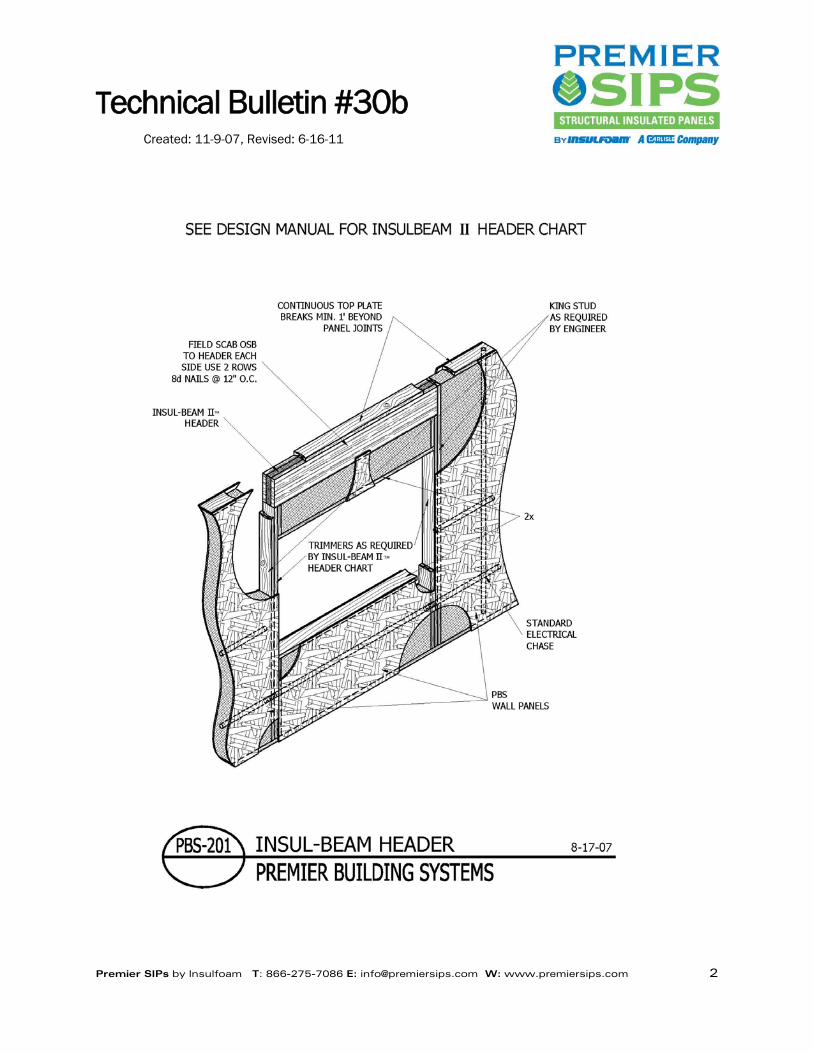
For typical situations, Premier SIPs requires the built up headers be placed directly beneath the top plate of the
wall and the trimmer studs extend up to the underside of the header. King studs are then added and attached
to the trimmer studs as required by the structural design. By using this methodology, the built up header
transfers the gravity loads to the trimmer studs through bearing and the wall panel below the header transfers
the wind loading to the king studs attached to the trimmer studs. Detail PBS-201 shows this configuration for
a wall.
If the header is to be placed directly above the opening, a plate, the same width as the wall panel is nailed to
the top of the header which will provide bearing for the OSB skins of the panel above the header. Detail PBS-
211 depicts this condition.
For gable wall situations either of the previously described methods can be used for the header. If the header
is placed directly below the top plate of the gable wall panel, the ends of the header will have to be plumb cut
to match the slope of the wall.
Technical Bulletin #30b
Created: 11-9-07, Revised: 6-16-11
Premier SIPs by Insulfoam T: 866-275-7086 E: [email protected] W: www.premiersips.com 2

Technical Bulletin #30b
Created: 11-9-07, Revised: 6-16-11
Premier SIPs by Insulfoam T: 866-275-7086 E: [email protected] W: www.premiersips.com 3

Technical Bulletin #31b
Created: 12-10-07, Revised: 6-16-11
Premier SIPs by Insulfoam T: 866-275-7086 E: [email protected] W: www.premiersips.com 1
LOW SLOPE COMMERCIAL ROOFING WITH PREMIER SIPs ROOF PANELS
Low slope commercial roofing with Premier SIPs is used in residential and commercial building applications.
Commercial applications of Premier SIPs on a roof are typically low slope applications that require a contractor
to have full understanding of code requirements.
Low slope roof applications typically utilize a single ply roofing membrane, built up roof (BUR) or modified
bitumen as the roofing system. Within these systems are several techniques to secure the roof system to the
panels. These include ballasted, adhered and mechanical attachment. Ballasted systems rely on rock or
cementitious pavers as a weight to hold the membrane in place. Mechanical attachment is accomplished with
the use of large screws through a membrane. Adhered systems use asphalt or adhesives that are placed on a
substrate or carried on the membrane to adhere the membrane to the underlying deck. In some attached
systems, the adhesive layer is applied to a board or sheet that has been mechanically attached to the deck.
When Premier SIPs are used as the deck on a low slope roof system, Premier SIPs recommends that a
divorcement material be placed over the panels prior to the roof membrane. This divorcement can be a slip
sheet on ballasted systems, a nailed base sheet on BUR systems and a cover board such as gypsum or wood
fiber with adhered systems. These divorcement materials will minimize the effect of removing the roof
membrane in the future, should it fail or need to be replace. The panels require this protection since they need
to remain intact to provide the structural capacities they were designed to support.
Further consideration needs to be given regarding the local building codes in effect and the architectural
requirements of the roof assembly. Most jurisdictions in the United States follow the International Building
Code (IBC) for commercial roof applications. Within the code is the requirement that the roof system meet a
Class A, B or C designation based on ASTM E108 or UL 790 testing. When roof systems are placed over a
Premier SIPs panel, a Class A, B or C rating needs to be determined for a combustible deck. In addition most
architectural requirements for roof systems call out for a Class A roof system. The architect and roofing
contractor need to be aware of the proposed roof membrane assembly to achieve a Class A rating over a
combustible deck. Many times the easiest method to achieve the Class A requirement is to include a layer of
gypsum board such as ¼” DensDeck® over the panels. The attachment of this board needs to be sufficient to
meet wind uplift requirements when used in conjunction with adhered membranes. In all cases the
divorcement material should meet the requirements of the roofing membrane manufacturer.
When adhered systems are to be placed over Premier SIPs it is recommended that the membrane be attached
with asphalt, pre applied pressure sensitive adhesives or water based adhesives. Solvent based adhesives
could cause deterioration in the core of the Premier SIPs.
DensDeck® is a registered trademark of Georgia-Pacific.
Technical Bulletin #32b
Created: 4-14-08, Revised: 6-16-11
Premier SIPs by Insulfoam T: 866-275-7086 E: [email protected] W: www.premiersips.com 1
SEALING REQUIREMENTS FOR PANELS USED IN COMMERCIAL CONSTRUCTION
Premier SIPs are often used in commercial construction for floors, walls and or roofs. The proper use of vapor
retarders and SIP Tape in these applications is a common question. The purpose of this technical bulletin is to
provide guidelines for the use of vapor retarders, SIP Tape and panel mastic with Premier SIPs in commercial
applications.
When installing Premier SIPs, the proper placement, as shown in the Premier SIPs details, of panel mastic at
all panel joints is required. The function of the mastic is to provide a seal against air and vapor transmission.
The Building Codes view commercial construction in a different light than residential construction. In
commercial construction, framed walls, floors and ceilings not ventilated to allow moisture to escape are
required to have vapor retarders installed on the warm-in-winter side of the insulation. Commercial
applications address ventilation through mechanical air handling and heat/cooling equipment. The key here is
proper ventilation.
Commercial construction, typically, has a mechanical engineer involved with the design of the ventilation
system. The mechanical engineer’s design will take into account the amount of ventilation the structure
requires based on the intended use of the building. In most applications this ventilation provides for numerous
air changes which precludes the need for SIP tape or other vapor retarders. In addition, commercial structures
intended to be used for storage or general warehouse do not need additional vapor control methods.
Buildings with intended uses involving pools, spas, or other high humidity conditions need to be looked at very
carefully by the mechanical design professional with regard to adequate ventilation. In high humidity
environments special attention to joint sealing and the use of SIP tape must be addressed.
In commercial construction that does not meet the ventilation requirements of the building code, Premier SIPs
suggests that the IBC, as modified or approved by the local building code jurisdiction, be followed with regard
to installing a vapor retarder.
If a vapor retarder is required in your commercial project, Premier SIPs recommends the use of SIP Tape over
the panel joints. The SIP Tape is formulated with a permeance of less than 1. The APA has determined that
OSB has a perm rating of less than 1. Since the OSB skins, of the panels that PBS produces, have a
permeance rating of less than 1, the panel joint is the primary area of concern with a SIP system. The
combination of the OSB skins and the SIP Tape meets the building code requirements for vapor retarders.
Premier SIPs requires that panel mastic be used when joining panels.
Typically, 6” wide SIP Tape is used at all wall and roof panel joints as well as at wall panel corners. The
connection of roof panels to exterior wall panels requires the use of 12” wide SIP Tape. Roof panels that have
joints on supporting beams require 18” wide SIP Tape. A ridge beam is an example of this condition.
Please refer to the Premier SIPs typical details for illustrations of these conditions. The typical details can be
requested by calling the number below, or it can be viewed online at www.premiersips.com.
Technical Bulletin #33d
Created: 8-19-08, Revised: 9-10-12
Premier SIPs by Insulfoam T: 866-275-7086 E: [email protected] W: www.premiersips.com 1
PREMIER SIPs USED AS SHEAR WALLS
Premier SIPs have been used as shear walls for many years in all types of shear wall applications including
high wind areas and high seismic locations. Insulfoam maintains two different listing reports for Premier SIPs.
Each agency that authored the respective reports has used a different methodology to evaluate Premier SIPs
as shear walls.
The different methodologies used to evaluate the Premier SIPs shear wall capacity reflects the current state of
the structural engineering community when it comes to evaluating materials used as shear walls. As the
engineering community learns more about high wind and high seismic activities the methodologies used to
evaluate these materials as shear walls is changed and updated to reflect the most current knowledge
available to the structural engineering community.
At this point in time, shear wall evaluation for all types of materials not currently covered in the building code is
changing at a rate that is difficult to keep up with. Insulfoam is committed to working with the structural
engineering community to stay current with Premier SIP shear wall evaluation methodologies. Please contact
your Premier SIPs Sales Rep or the Technical Center to obtain your copy of the most current listing reports.
Technical Bulletin #34b
Created: 3-25-09, Revised: 6-17-11
Premier SIPs by Insulfoam T: 866-275-7086 E: [email protected] W: www.premiersips.com 1
ENERGY CALCULATIONS AND PREMIER SIPs
Energy efficiency is paramount in today’s economy. Most everyone is concerned about conserving our natural
resources and finding alternate sources of energy. Premier SIPs are helping Americans reduce energy use.
Compared to traditional “stick built” construction, Premier SIPs save building owners up to 60% on monthly
utility bills.
HVAC professionals are able to account for this energy efficiency in the design of the mechanical systems in
Premier SIPs homes provided they have the proper information. Mechanical professionals use ACCA (Air
Conditioning Contractors of America) Manual J as the design guide to calculate the requirements for the
heating and cooling systems in our residential structures. Today, these calculations are computer based, but
two important Premier SIPs properties need to be input into the software to provide meaningful results.
Manual J based calculations require the R-Value of the insulation material and the air infiltration rate, or air
leakage rate. The R-Value is relatively straight forward. However, the air infiltration rate for Premier SIPs must
be addressed properly. Design guidelines for Manual J calculations suggest a reasonable air leakage
assumption between 0.35 to 0.50 natural air-changes per hour, unless a builder has data specific to their
construction practices indicating they build tighter (or looser). This recommendation is for stick built homes.
Premier SIPs has blower door test data generated from homes using SIPs for the exterior walls and roof of
homes that test out at .04 to .06 natural air changes per hour. These values for SIPs are on the order of 10
times better than what the Manual J design guidelines suggest. This reinforces what home owners have
known for years about Premier SIPs energy efficiency.
Premier SIPs recommends that a value of .05 natural air changes per hour be used when performing Manual J
heat loss calculations on homes using Premier SIPs as the exterior walls and roof. If the software being used
does not allow for numerical input, select the tightest option.

Technical Bulletin #35b
Created: 6-22-10, Revised: 6-17-11
Premier SIPs by Insulfoam T: 866-275-7086 E: [email protected] W: www.premiersips.com 1
BREATHABLE ROOFING UNDERLAYMENT’S AND PREMIER SIPs
One of the many benefits of building with Premier SIPs is speed of construction. Speed of roof installation is
especially beneficial in climates where precipitation is prevalent. However, precipitation during installation of
roof panels and roofing materials should be properly addressed. The proper construction methodology and
sequencing for the installation of roofing assemblies is to allow the OSB to dry adequately prior to the
installation of the roofing underlayment.
When and if these conditions present themselves on your project, you may want to consider the use of a
synthetic, breathable roofing underlayment as an alternative to traditional 15# or 30# roofing felts underneath
the final roof covering. Breathable roofing underlayment’s have perm ratings much greater than one. These
materials allow water vapor to pass through the membrane yet restrict the bulk water movement back through
the membrane toward the OSB skin of the SIP roof panel.
The idea behind this concept is to allow water that maybe trapped in the OSB to pass though the synthetic
roofing underlayment as a vapor and once on the exterior side of the membrane it can eventually evaporate or
condensate on the underside of the roofing material and run off the roof.
There any many manufactures of breathable underlayment’s in North America. A quick internet search will
turn up manufactures and suppliers available to supply your project. Be sure to check with the manufacture of
the breathable underlayment for the perm rating of the underlayment and to see if there are any compatibility
issues with asphalt shingles or the finished roof covering material you are using on your project.
Technical Bulletin #36b
Created: 5-26-11, Revised: 6-17-11
Premier SIPs by Insulfoam T: 866-275-7086 E: [email protected] W: www.premiersips.com 1
PREMIER SIPs – CONTINUOUS INSULATION SHEAR VALUE
Energy efficiency is paramount in building construction. Many local building codes are following the lead of
ASHRAE and adopting requirements for continuous insulation (ci) over stud framed walls. Premier SIPs
continuous insulation product is an answer to these local building code requirements.
Premier SIPs continuous insulation product consists of a layer of OSB laminated directly to an Insulfoam EPS
insulation core. When the continuous insulation product is attached to the stud wall framing the OSB is held
off the studs by the thickness of the EPS. This framing method varies from the typical application of OSB
nailed directly to the stud framing. Questions about the racking shear capacity of this type of assembly have
been raised by designers. The APA has published Technical Note 465E, APA Rated Siding Panels Over Rigid
Foam Insulation Sheathing, which address this question for insulation thicknesses up to one inch.
Cyclic racking shear wall testing was conducted for applications using Insulfoam EPS insulation thickness of
1.5 inches. The assembly consisted of 7/16” Exposure 1 Oriented Strand Board (OSB) over 1.5 inches of
Insulfoam EPS and nailed with 0.131 inch diameter x 3 ¼” nails driven by a pneumatic nail gun. The nails
were driven through the OSB and foam and into the 2x4 studs behind. The 2x4 stud spacing was 24 inches on
center. Nail spacing was 3 inches on center at the OSB edges, and 6 inches on center in the field of the OSB.
The cyclic testing was conducted using the CUREE protocol according to AC 130. The average maximum load
for the assembly was 557 plf. Designers can use this value with the appropriate safety factor to design walls
utilizing this assembly.
Technical Bulletin #37a
Created: 1-17-12, Revised: 1-17-12
Premier SIPs by Insulfoam T: 866-275-7086 E: [email protected] W: www.premiersips.com 1
SEALING PREMIER SIPs
Building science has taught us that a tight building envelope significantly contributes to the energy efficiency of
the structure. Building science has also shown us that SIPs can significantly reduce air leakage through the
building envelop. This reduction in air leakage significantly contributes to the energy efficiency of a SIP
structure.
If a structure using Premier SIPs is going to realize the reduced air leakage that contributes to the energy
efficiency of the SIP system, the details relating to the sealing of the SIP panel joints and connections need to
be followed. Designers and contractors are encouraged to become thoroughly familiar with the Premier SIPs
technical bulletins and details that describe proper use of mastic and SIP tape.
Expanding foam sealants compatible with EPS must be used to seal penetrations made in the SIPs during the
construction process. This would include any penetrations from the construction process as well as
penetrations for the HVAC, plumbing and electrical systems. These penetrations need to be thoroughly and
completely sealed. Proper sealing of the electrical chases in panels as well as the electrical boxes within the
panels would be included in this process.
By paying attention to the sealing of penetrations, SIP panel joints and connections in your Premier SIPs
structure you will ensure that your structure has minimal air leakage through the exterior envelop thus helping
to maximize the energy efficiency of the Premier SIPs system.
Technical Bulletin #38a
Created: 1-17-12, Revised: 1-17-12
Premier SIPs by Insulfoam T: 866-275-7086 E: [email protected] W: www.premiersips.com 1
MOISTURE CONTENT OF LUMBER USED IN PREMIER SIPs
Integral to the construction of a Premier SIP structure is the lumber used as plating and splines in the Premier
SIPs. Premier SIPs are designed to be used with kiln dried lumber. Kiln dried lumber has a moisture content
at or below 19%. The reason for this requirement is to minimize any shrinkage of the lumber used within the
panels thus reducing the potential for unsealed gaps and cracks.
It is a well know fact that lumber with a moisture content in excess of 19% may see considerable shrinkage as
the lumber dries down to an equilibrium moisture content less than 19%. If this shrinkage occurs within a SIP
panel, gaps or cracks may open that provide a pathway for the movement of air. This air may contain moisture
and if this moisture laden air meets a surface with a temperature at or below the dew point of the air,
condensation will occur. The use of lumber with a moisture content of 19% or less will reduce the potential for
lumber shrinkage and minimize potential issues associated with any shrinkage.