Embed Size (px)
Citation preview

1
Postal PenguinAn Unmanned CombatAir Vehicle for the Navy
Team 8-BallFinal PresentationApril 22nd, 2003

2
AgendaIntroductionBackground ResearchConcept Overview, SelectionDesign Evolution, WeightsFinal ConfigurationSystems OverviewAero-PerformanceControl & StabilityStructural AnalysisPelikan TailAutonomy, Carrier IntegrationCostSummary and Questions

3
IntroductionTeam Members and Positions
Justin HayesBen Smith Greg Little
David Andrews Chuhui Pak
Nate Wright Alex RichJon Hirschauer
Christina DeLorenzo

4
IntroductionRequest for Proposal Overview
Structural LoadsCarrier OpsOblique AnglesSurvivabilityStealth
Volume, IntegrationGlobal HawkSensor SuiteEngine, Aero Performance> 40,000 ftCeiling
No Supersonic, Engine> M 0.7Cruise SpeedInternal Volume4,600 lbsPayload
Low TSFC, High Fuel10 HrsMission 2, EnduranceHigh Fuel Requirements500 nmMission 1, Strike RangeEffect of SpecificationSpecificationRFP Requirement

5
IntroductionProject Drivers
Store Capacity
Flyaway CostsStealth
Carrier Operation Fuel
Sensor Suite
(Pictures Courtesy of Global Security)

6
AgendaIntroductionBackground ResearchConcept Overview, SelectionDesign Evolution, WeightsFinal ConfigurationSystems OverviewAero-PerformanceControl & StabilityStructural AnalysisPelikan TailAutonomy, Carrier IntegrationCostSummary and Questions

7
Background ResearchExisting Aircraft
(Pictures Courtesy of GlobalSecurity)

8
Background ResearchAdvanced Technologies, VSTOL
0
2
4
6
8
10
12
14
91 92 93 94 95 96 97
Fiscal Year
Mis
haps
per
100
,000
Flig
ht H
ours
AV-8b Harrier Jump Jet
All Other Navy Aircraft
Harrier Review Panel Study (HaRP)
Increased Failure Rates55 Peacetime Vehicle Losses (17 lives lost)Mishap Rates of 14-20 per 100,000 hrs
Increases Weight, Cost, Volume

9
AgendaIntroductionBackground ResearchConcepts Overview, SelectionDesign Evolution, WeightsFinal ConfigurationSystems OverviewAero-PerformanceControl & StabilityStructural AnalysisPelikan TailAutonomy, Carrier IntegrationCostSummary and Questions
10
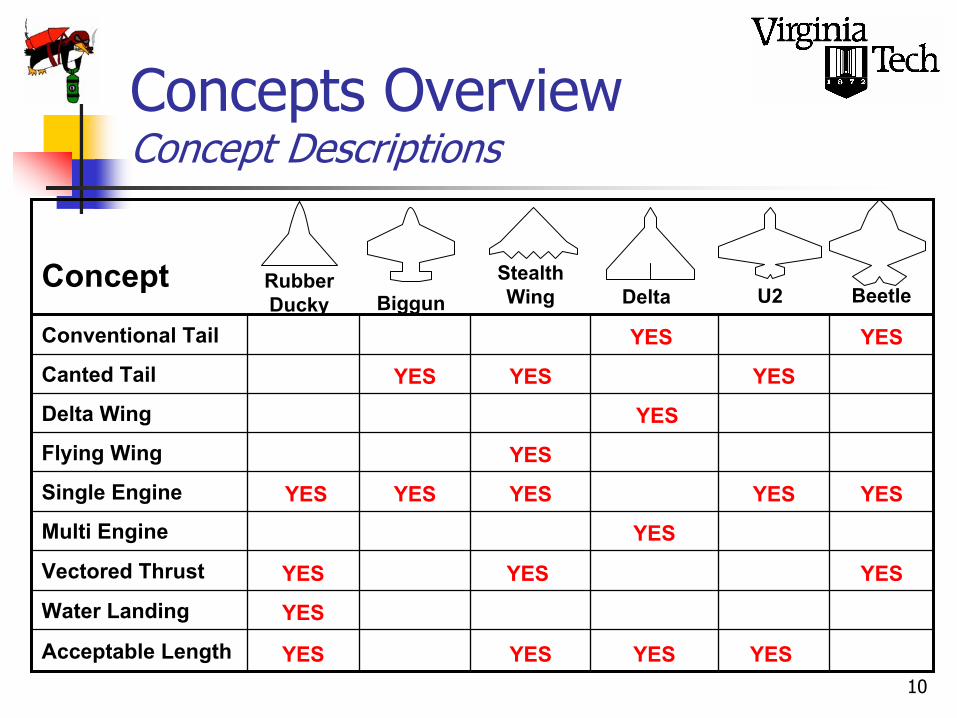
Concepts OverviewConcept Descriptions
YESYESYESYESAcceptable Length
YESWater Landing
YESYESYESVectored Thrust
YESMulti Engine
YESYESYESYESYESSingle Engine
YESFlying Wing
YESDelta Wing
YESYESYESCanted Tail
YESYESConventional Tail
Concept Stealth Wing BeetleDelta U2Biggun
Rubber Ducky

11
Concepts OverviewReduction Chart
Stealth Wing Beetle Delta U2 Biggun Rubber Ducky

12
AgendaIntroductionBackground ResearchConcept Overview, SelectionDesign Evolution, WeightsFinal ConfigurationSystems OverviewAero-PerformanceControl & StabilityStructural AnalysisPelikan TailAutonomy, Carrier IntegrationCostSummary and Questions

13
Design Evolution, WeightsInitial Configuration, Problems
Severe Instability(21% MAC)Significant cg Travel
Landing ProblemsDrag DivergenceFuel Volume
14
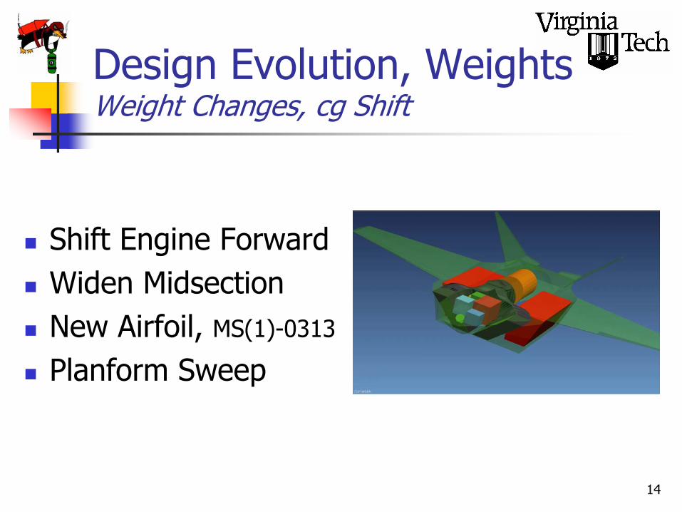
Design Evolution, WeightsWeight Changes, cg Shift
Shift Engine ForwardWiden MidsectionNew Airfoil, MS(1)-0313
Planform Sweep

15
Design Evolution, WeightsSolving the Weights Problem
JDAM, pre-drop
HARM, pre-drop
JDAM/HARM, post-drop
Loiter
JDAM
HARM
Ordinance Release Ordinance Retention

16
AgendaIntroductionBackground ResearchConcept Overview, SelectionDesign Evolution, WeightsFinal ConfigurationSystems OverviewAero-PerformanceControl & StabilityStructural AnalysisPelikan TailAutonomy, Carrier IntegrationCostSummary and Questions

17
Final ConfigurationPostal Penguin Layout

18
Final ConfigurationPostal Penguin Internal Layout
Integrated Sensor Suite
Fuel Tanks
Inlets
Main Gear
Nose Gear
EngineExhaust
Payload
Wing Tanks

19
FlapsAilerons
Air intake
Pelikan Tails
Nose Gear
Main Gear
Final ConfigurationPostal Penguin External Layout

20
Final ConfigurationFor Dr. Brown
22.7°Λo4.35AR125 kntVLand14.3'HeightMax
130-150 kntVLaunch30'SpanFolded
105 kntVStall45'Span16-34.5 kipsWeight32'Length
General Characteristics

21
Final ConfigurationPenguin Top/Side View
Length 35’Folded Length 32’Span 45’Folded Span 30’Wheelbase 15’Track Width 10’

22
Final ConfigurationPenguin Front View

23
AgendaIntroductionBackground ResearchConcept Overview, SelectionDesign Evolution, WeightsFinal ConfigurationSystems OverviewAero-PerformanceControl & StabilityStructural AnalysisPelikan TailAutonomy, Carrier IntegrationCostSummary and Questions

24
Systems OverviewGeneral Systems
Electrical
Defensive
Engine
Weapons
Bomb Bay
Landing Gear
Hydraulics
Command/Control
Flight Control
(Pictures Courtesy of GlobalSecurity, FAS)

25
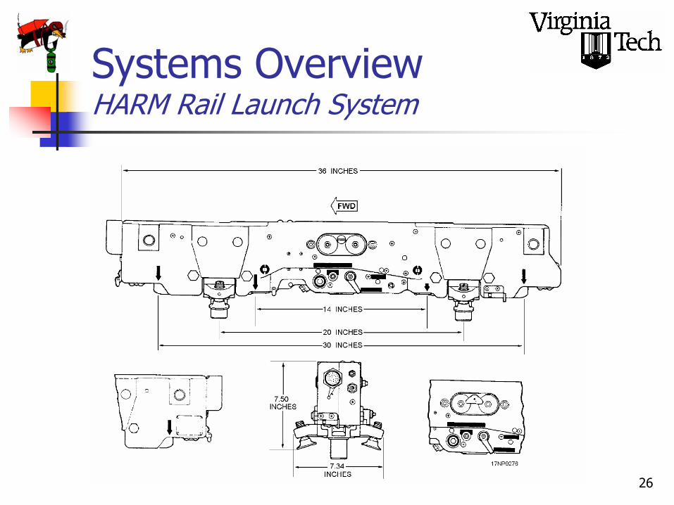
Systems OverviewBomb Bay, HARM
Must be rail launchedUtilize already existing technologyLAU-118/A Guided Missile LauncherBRU-32/A Bomb Rack
(Courtesy of GlobalSecurity)
26
Systems OverviewHARM Rail Launch System

27
Systems OverviewJDAM Pneumatic Ejector
Utilize already existing technologyPneumatic Ejector RacksThe Advantages of Pneumatic Ejection

28
PlacementSizeGeometric RetractionWeight: 600 lbsTires – Type VII
Ground Clearance
Systems OverviewMain Gear
Diameter: 25.84 in.Width: 7.30 in.
cg

29
Systems OverviewNose Gear
PlacementGeometric RetractionWeight: 600 lbs
SizeTires – Type VII
Diameter: 18.27 in.Width: 4.27 in.
30 35 40 45 50 55 600
0.5
1
1.5
2
2.5
3
3.5
4
4.5
5
5.5x 10⁴
Length
Wei
ght
Weight vs. Length

30
AgendaIntroductionBackground ResearchConcept Overview, SelectionDesign Evolution, WeightsFinal ConfigurationSystems OverviewAero-PerformanceControl & StabilityStructural AnalysisPelikan TailAutonomy, Carrier IntegrationCostSummary and Questions

31
General Characteristics:Supercritical airfoil for drag divergenceModerate sweep for transonic performance/neutral point locationHigh span and area for good L/D characteristicsReasonable thickness for potential fuel storage
45’If Penguins Had Wings…
22.65 deg
11.4 ft
MAC
10 deg465 ft45 ft.0.294.35
Λ 1/2SbλAR
Aero-PerformanceAerodynamic Considerations

32
Aero-PerformanceThe Contenders
MS(1)-0313
SC(2)-0712 MS(1)-0317 MS(1)-0313
0.130.170.12t/c
5.26.83.1α max
1.421.381.3CL max
MS(1)-0313MS(1)-0317SC(2)-071240 kft
The Penguin presented unique design requirements:High L/D, good low-speed lift, all in a very small package.Some characteristics looked at are below.
The MS(1)-0313 provided the best combination of characteristics.

33
Example drag polarfor the cruise altitudeof 40,000 ft (deepstrike/SEAD missions)The marker signifiesmaximum L/D of 13.8
Drag Polar (40,000 ft)
0
0.2
0.4
0.6
0.8
1
1.2
1.4
1.6
0 0.02 0.04 0.06 0.08 0.1 0.12 0.14 0.16 0.18
CD
CL
L/D)MAX = 13.8
Aero-PerformanceDrag Polar, Build-up

34
A supercritical airfoil alone is not enough to counter the effects of increased wave drag.Wing has been swept 10 deg at mid-chord to raise Mach drag divergence.
CL vs. MDD
0.64
0.66
0.68
0.7
0.72
0.74
0.25 0.45 0.65 0.85 1.05 1.25CL
MDD
10 deg5 deg0 deg
Aero-PerformanceSweep and MDD

35
While sacrificing fuel volume, the decreased thickness in the wings allowed for great improvement in the Mach drag divergence values for all potential angles of sweep.
Midchord Sweep vs. MDDCL = 0.5
0.66
0.68
0.7
0.72
0.74
0.76
0.78
0.8
0.82
0 10 20 30 40Midchord sweep (deg)
MD
D 13 % t/c17 % t/c
Aero-PerformanceThickness and MDD

36
Requirements refresher:0.85 Mach at Sea Level0.7 Mach (or better) cruise speed at 40kft or better (Deep Strike/SEAD)10 hour endurance/loiter mission8400 ft/min (or better) initial climb rate
0.71 M0.54 M13.857,700 ft
Range VelocityLoiter VelocityL/D MaxCeilingOther
150 kts131 kts109 kts5g
T/O speedApproach SpeedStall SpeedT/O Accel.Carrier
10260 ft/min0.83 M550 nm14.5 h
Initial ROC (SL)Max Speed (SL)Range (40,000 ft)EnduranceRFP
Aero-PerformancePerformance Factors

37
AgendaIntroductionBackground ResearchConcept Overview, SelectionDesign Evolution, WeightsFinal ConfigurationSystems OverviewAero-PerformanceControl & StabilityStructural AnalysisPelikan TailAutonomy, Carrier IntegrationCostSummary and Questions

38
117.66 knots
Take Off Rotation SpeedJDAM MISSION
HARM MISSION121.29 knots
LOITER MISSION121.83 knots
Aileron Size 7.28 ft^2Flap Size 13.49 ft^2Rudder Size 16.84 ft^2
Control and StabilityControl Surface Sizing
39
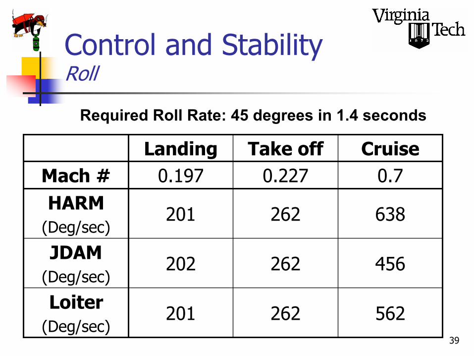
Required Roll Rate: 45 degrees in 1.4 seconds
562262201Loiter(Deg/sec)
456262202JDAM(Deg/sec)
638262201HARM(Deg/sec)
0.70.2270.197Mach #CruiseTake offLanding
Control and StabilityRoll

40
Sideslip Flight ( Beta = 11.5 deg )
CruiseLandingTake Off
6.922.6712.64PHI
(degrees)
0.210.320.31Delta R
(degrees)
1.831.811.82Delta A
(degrees)
0.70.2270.197Mach #
Control and StabilityHARM Mission
41
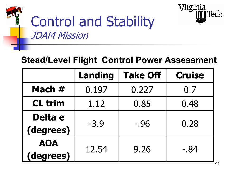
Stead/Level Flight Control Power Assessment
CruiseTake OffLanding
-.849.2612.54AOA
(degrees)
0.28-.96-3.9Delta e
(degrees)
0.480.851.12CL trim0.70.2270.197Mach #
Control and StabilityJDAM Mission

42
AgendaIntroductionBackground ResearchConcept Overview, SelectionDesign Evolution, WeightsFinal ConfigurationSystems OverviewAero-PerformanceControl & StabilityStructural AnalysisPelikan TailAutonomy, Carrier IntegrationCostSummary and Questions

43
Structural AnalysisMaterial Usage
Large, One-Piece, Carbon Composites Titanium, Ceramic
Radar Absorbent PaintTitanium
BMI
Silicon
AramidComposites

44
Structural AnalysisWing Box Layout
Skin Stiffeners
LE Spar
Aft Spar
Aileron
45
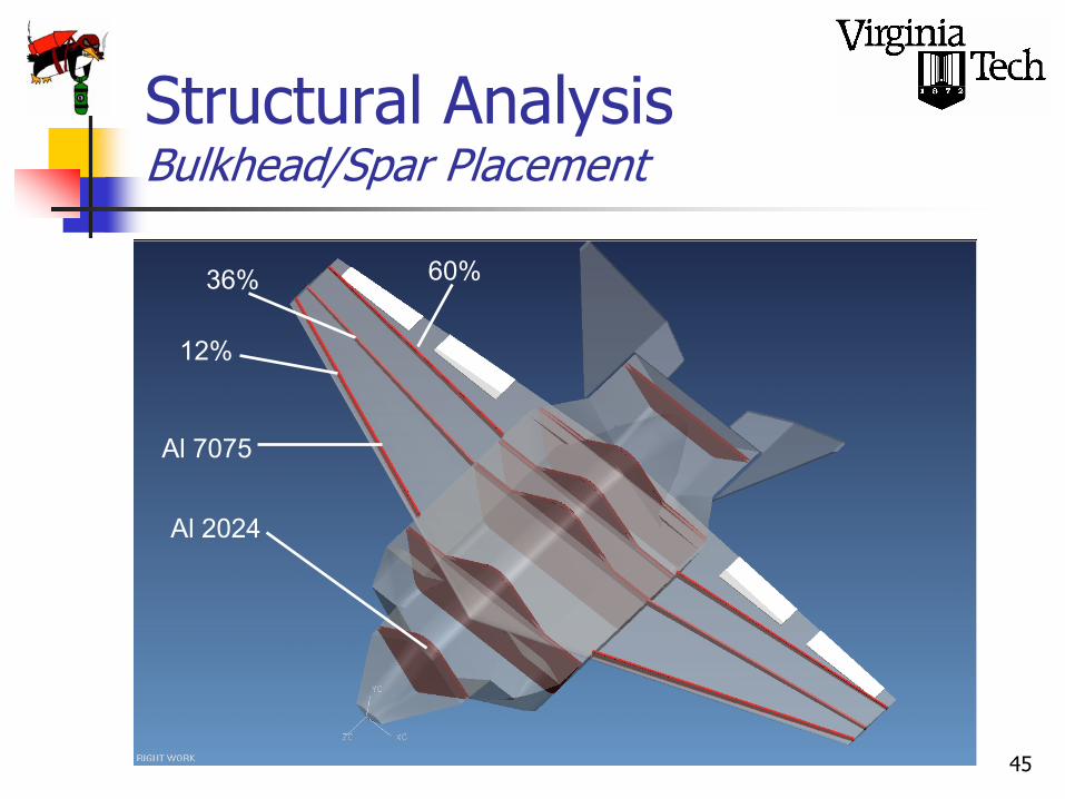
Structural AnalysisBulkhead/Spar Placement
12%
36% 60%
Al 7075
Al 2024

46
Structural AnalysisBulkhead Placement
Nose Gear Tie In Main Gear
Tie In
Aft Tail, Tail Hook Support
Engine SupportLeading Edge Spar, Inlet Support
Exhaust Support

47
Structural AnalysisEngine Bulkhead Design
Engine mounts
Ordinance mounts
Supporting plateRemovable piece
Weapons bay doors
Navy requires engines be removable through bottom of airframe

48
AgendaIntroductionBackground ResearchConcept Overview, SelectionDesign Evolution, WeightsFinal ConfigurationSystems OverviewAero-PerformanceControl & StabilityStructural AnalysisPelikan TailAutonomy, Carrier IntegrationCostSummary and Questions

49
Pelikan TailAbout the Pelikan Tail
What is a Pelikan tail?Why do we want to use it?Testing the Pelikan Tail

50
Pelikan TailWhat Is the Pelikan Tail?
A tail configuration that obtains yaw and pitch control through the use of two rear control surfaces. Named for Ralph Pelikan.

51
Pelikan TailLook at our Model
Courtesy: NOVA JSF Video

52Induced rolling moment will be countered by control system & ailerons.Opposite deflection causes equivalent side forces, creating yaw.
POSITIVE DEFLECTION
NEGATIVE DEFLECTION
Pelikan TailObtaining Yaw

53
Pelikan TailWhy Use a Pelikan Tail?
StealthFewer vertical surfaces reduces RCS
Other FactorsLess skin friction drag Only 2 actuated rear control surfacesUnproven design

54
Pelikan TailImportance of Stealth
The stealth of the aircraft keeps it safe from the enemyInterceptors are faster & more agile, survivability depends on stealth Stealth CAN provide all of an aircrafts survivability:
Courtesy: www.fas.org

55
Pelikan TailOther Factors
DragThe less skin friction drag the better
Fewer rear control surfacesOnly 2 hydraulic actuators, less weight
Unproven DesignOpportunity to explore a new idea with physical testingNo previous examples to justify Pelikan tail implementationCan we get enough side force?

56
Senior Design / Junior Lab PartnershipDr. Mason & Dr. DevenportWould provide futuresenior design teamswith the opportunityto test their designsWould expose juniors to a vast array of different aerodynamicdesigns.
Promote healthy Junior / Senior relations!
2003
2004
CLASSOF
Pelikan TailTesting

57
Pelikan TailModel Construction
Draft tail sections in UniGraphicsConstruct base plate (poplar)Fabricate tail sections with 3D printerCoat with epoxy, then fiberglassEpoxy hinges & attach deflection braces

58
53o
9”
4”
Tail Airfoil Section – NACA 0012
*Note: Drawings not to scale
Hinge Angle = 15o
23”
12”
Base Plate8”
Pelikan TailModel Dimensions

59
Pelikan TailExperimental Goals
Can we obtain the Yaw force needed?Will Pitch controls produce excess Yaw?Discover any unexpected characteristics
We do not have direct control over the testing process

60
Pelikan TailPictures
(Pictures Courtesy of Perez’s Junior Lab Group)

61
-0.600
-0.400
-0.200
0.000
0.200
0.400
0.600
-6.0 -4.0 -2.0 0.0 2.0 4.0 6.0
Angle of Attack (degrees)
CY
L-Neg / R-Pos
L-Pos / R-Neg
R-Neg / L-Zero
Both Negative
Both Positive
R-Pos / L-Zero
Both Zero
V = 80mph
Re = 540,000
CY
CY vs. Angle of Attack
Pelikan TailTesting Data
(Data from Perez’s Junior Lab Group)

62
Pelikan TailTest Conclusions
We can obtain the Yaw needed.There is little Yaw effect in pitch.Testing still in progress.
From what data we have we believe that the Pelikan tail is a viable tail design.

63
Thank you to the TAs and students who participated in this concept test
Rafael Perez’s Lab GroupNanyaporn Intaratep’s Lab GroupAny groups to test this week
Pelikan TailConclusion
Additional thanks to Dr. Devenport and Dr. Mason for this unique opportunity and we hope this partnership continues in the years to come.

64
AgendaIntroductionBackground ResearchConcept Overview, SelectionDesign Evolution, WeightsFinal ConfigurationSystems OverviewAero-PerformanceControl & StabilityStructural AnalysisPelikan TailAutonomy, Carrier IntegrationCostSummary and Questions

65
AutonomyMission Logic
Launch
Climb
Waypoint Cruise
Combat Approach
Seek Target
ReleaseStores
AbortAttack
Retreat/Cruise
Land
SEAD ISRLaunch
Climb
Waypoint Cruise
ISR Pattern Search
Land
Return Information
Command/Control

66
AutonomyFlight Controls, Weapons Arming
Fly-by-WirePre-Programmed MissionsAutonomous Capability
ISRSEAD
Auto Pre-launch Weapons ArmingPin-Puller Mechanisms, Electronic

67
Carrier IntegrationAutonomous Integration, “Spot”
Autonomous Movement in CarrierPrecise Placement and ManueveringLessens Crew Requirements
“SPOT”(Courtesy of Alec Gosse)

68
Carrier IntegrationCarrier Characteristics
EMALSLanding and Stowing Procedure
2830# UCAVs32Launch Angle (deg)45Acceleration (g’s)285200Take-off Length (ft)33Deceleration348350Landing Length (ft)Design 2Design 1
Carrier Characteristics

69
AgendaIntroductionBackground ResearchConcept Overview, SelectionDesign Evolution, WeightsFinal ConfigurationSystems OverviewAero-PerformanceControl & StabilityStructural AnalysisPelikan TailAutonomy, Carrier IntegrationCostSummary and Questions
70
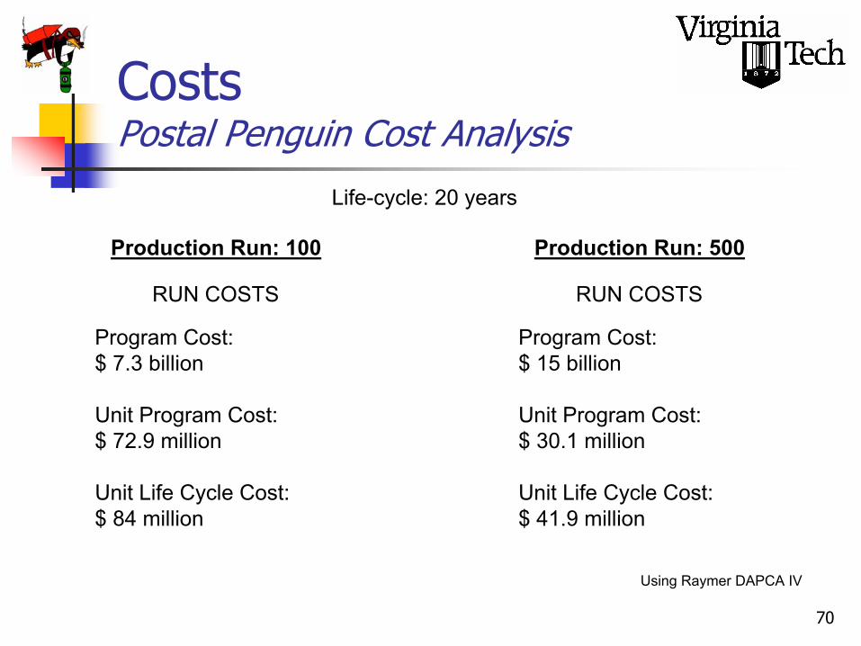
Life-cycle: 20 years
RUN COSTS
Production Run: 100
Program Cost:$ 7.3 billion
Unit Program Cost:$ 72.9 million
Unit Life Cycle Cost:$ 84 million
RUN COSTS
Production Run: 500
Program Cost:$ 15 billion
Unit Program Cost:$ 30.1 million
Unit Life Cycle Cost:$ 41.9 million
CostsPostal Penguin Cost Analysis
Using Raymer DAPCA IV
71
AgendaSummary
IntroductionBackground ResearchConcept Overview, SelectionDesign Evolution, WeightsFinal ConfigurationSystems OverviewAero-PerformanceControl & StabilityStructural AnalysisPelikan TailAutonomy, Carrier IntegrationCostSummary and Questions

72
Questions
Thank You,
We appreciate your time andattendance

73
ReferencesCarrier Suitability Testing Manual, Pax River MD Rev 2, Sept 1994Boeing Corporate Website, http://www.boeing.comDoyle, Michael R. Electromagnetic Aircraft Launch System – EMALS, Naval Air Warfare Center, Aircraft Division, Lakehurst, NJ 08733Northrop Corporate Website, http://www.ng.comGlobal Security Website, http://www.globalsecurity.comRaymer, Daniel P. Aircraft Design. Reston: AIAA, 1999Kennedy, Michael, Younossi, Obaid, Graser, John C. Military Airframe Costs, The Effects of Advanced Materials and Manufacturing Processes. Santa Monica: Rand, 2001Eden, Paul and Moeng, Soph. Modern Military Aircraft Anatomy. New York: Friedman/Fairfax, 2002Niu, Michael C. Airframe Structural Design. Los Angeles: Conmilit Press, 1988Beer, Ferdinand P. and Johnston, E. Russel. Mechanics of Materials. New York: McGraw- Hill, 1992Kirschbaum, Nathan with Mason, W.H. Aircraft Design Handbook, Aircraft Design Aid and Layout Guide. Blacksburg: Virginia Tech, 1993NOVA Films, Battle of the X-Planes. Broadcast on PBS, 2003Mason, W.H. Configurational Aerodynamics. Online Notes, avail http://www.aoe.vt.edu/~Mason/Mason_f/ConfigAero.htmlWhitford, Ray. Fundamentals of Fighter Design. Shrewsbury: Longlife, 2002Knott, Eugene F., Schaeffer, John F. and Tuley, Michael T. Radar Cross Section. 2ed. Boston: ArtechHouse, 1993Jenn, David C. Radar and Laser Cross Section Engineering. Reston: AIAA, 1995Survivability BookMORE REFERENCES (freshman?)

![Mach number P w,test [bar] P model [bar] 1.8 -0.45 -0.20 0 ...ae342/18/lab2/lab2data.pdf · Mach 2.0 Snapshot . Mach 1.8 Snapshot . Mach 2.3 Snapshot Mach 2.2 Snapshot . P w,test](https://img.pdfslide.us/doc/110x75/5fb4e5220b26be1bae0aea08/mach-number-p-wtest-bar-p-model-bar-18-045-020-0-ae34218lab2-.jpg)