Embed Size (px)
Citation preview

Development of Obstruction Lighting Standards for Wind Turbine Farms James W. Patterson, Jr. November 2005 DOT/FAA/AR-TN05/50 This document is available to the public through the National Technical Information Service (NTIS), Springfield, Virginia 22161.
U.S. Department of Transportation Federal Aviation Administration
ote
tech
nica
l not
e te
chni
caot
e te
chni
cal n
ote
tech
nica

NOTICE
This document is disseminated under the sponsorship of the U.S. Department of Transportation in the interest of information exchange. The United States Government assumes no liability for the contents or use thereof. The United States Government does not endorse products or manufacturers. Trade or manufacturer's names appear herein solely because they are considered essential to the objective of this report. This document does not constitute FAA certification policy. Consult your local FAA airports office as to its use. This report is available at the Federal Aviation Administration William J. Hughes Technical Center's Full-Text Technical Reports page: actlibrary.tc.faa.gov in Adobe Acrobat portable document format (PDF).

Technical Report Documentation Page 1. Report No. DOT/FAA/AR-TN05/50
2. Government Accession No. 3. Recipient's Catalog No.
5. Report Date
November 2005
4. Title and Subtitle
DEVELOPMENT OF OBSTRUCTION LIGHTING STANDARDS FOR WIND TURBINE FARMS 6. Performing Organization Code
ATO-P 7. Author(s)
James W. Patterson, Jr.
8. Performing Organization Report No.
9. Performing Organization Name and Address
Federal Aviation Administration William J. Hughes Technical Center
10. Work Unit No. (TRAIS)
Airport and Aircraft Safety Research and Development Division Airport Technology Research and Development Branch Atlantic City International Airport, NJ 08405
11. Contract or Grant No.
12. Sponsoring Agency Name and Address
U.S. Department of Transportation Federal Aviation Administration
13. Type of Report and Period Covered Technical Note
Office of Aviation Research and Development Washington, DC 20591
14. Sponsoring Agency Code ATA-400
15. Supplementary Notes
Thomas Paprocki, Oswaldo Valdivieso, and James Newman of HiTec Systems provided technical support throughout the course of this developmental effort. 16. Abstract The U.S. Department of Energy has mandated that renewable energy sources, such as wind turbines, will provide 5 percent of the nation’s electricity by the year 2020. As a result, wind turbine farms are sprouting all over the USA; farms having over 200 turbines spread over mountain ranges up to 20 miles long are not uncommon. Standing at heights up to 442 feet, these structures are considered obstructions to air navigation. As such, these obstructions must be illuminated so the aircraft can easily identify and avoid them, while at the same time, minimizing any impact of the illumination on surrounding communities. The Federal Aviation Administration visited 11 wind turbine sites, each containing numerous turbines, to investigate their existing lighting installations, their appearance from the air in day- and nighttime, and how these lights affected the surrounding communities. Each investigation included documentation flights, still and video photographs, and interviews with both the local wind turbine developer and the local community. Considering the lighting concepts currently used for illuminating radio towers and long-span bridges, which states that obstructions near to each other should be treated as if they were one large obstruction, a similar lighting concept was adopted for illuminating the wind turbine farms. The lighting concept for wind turbine farms includes the use of red, simultaneously flashing lights positioned on the outer perimeter of the wind turbine farm, each spaced no more than one-half statute mile from each other, and requires only one fixture per turbine. As long as the wind turbines are painted white in color, daytime illumination is not required. A test site was established in Lawton, Oklahoma, to validate the new lighting concept. Research personnel conducted repeated evaluation flights of the test site, and confirmed that the proposed lighting concept provided approaching aircraft ample warning that the wind turbine farm was a single, very large obstruction that should be avoided. 17. Key Words:
Obstruction lighting, Wind turbine farms, L-864, L-865, L-810
18. Distribution Statement This document is available to the public through the National Technical Information Service (NTIS), Springfield, Virginia 22161.
19. Security Classif. (of this report)
Unclassified
20. Security Classif. (of this page)
Unclassified
21. No. of Pages
36
22. Price
Form DOT F 1700.7 (8-72) Reproduction of completed page authorized

TABLE OF CONTENTS Page EXECUTIVE SUMMARY v INTRODUCTION 1
Purpose 1 Background 1 Related Activities and Documentation 2
DISCUSSION 3
Approach 3 Procedures 3
FLIGHT EVALUATION OF EXISTING FACILITIES 4
Results of Existing Facilities Flight Evaluation 5
Somerset, Pennsylvania, Site 5 Clear Lake, Iowa, Sites 7 Midland/Odessa, Texas, Sites 9
Preliminary Recommendations for Existing Site Evaluations 16
FLIGHT VALIDATION OF RECOMMENDED CONFIGURATION 17
Validation Site Details—Lawton, Oklahoma 18 Flight Validation Activities—First Evaluation 19 Ground Observations 19 Flight Validation Activities—Second Evaluation 20 Supplemental Methods to Warn Pilots 21
CONCLUDING REMARKS 24
APPENDIX A—GUIDELINES FOR DEVELOPING LIGHTING PLANS FOR WIND TURBINE FARMS
iii

LIST OF FIGURES
Figure Page 1 Green Mountain Site, Somerset, Pennsylvania 6 2 Clear Lake Site, Clear Lake, Iowa 7 3 Top-of-Iowa Site, Joice, Iowa 8 4 McCamey Site, McCamey, Texas 9 5 Big Spring Site, Big Spring, Texas 10 6 Oak Creek, Tehachapi, California 13 7 Tehachapi Pass, Tehachapi, California 14 8 Externally Lit Turbine 16 9 Blue Canyon Wind Farm Layout 18 10 Blue Canyon Wind Farm Lighting Scheme 19 11 Typical Depiction of Wind Turbine Farm on Chart 22 12 Possible Icons for Indicating Single and Multiple Wind Turbines 22 13 Example of National Park Area Outline 23 14 Example of Oil Field Area Outline 23 15 Existing Obstruction Legend 23
iv

EXECUTIVE SUMMARY
The U.S. Department of Energy has mandated that renewable energy sources, such as wind turbines, will provide 5 percent of the nation’s electricity by the year 2020. As a result, wind turbine farms are sprouting all over the USA; farms having over 200 turbines spread over mountain ranges up to 20 miles long are not uncommon. Standing at heights up to 442 feet, these structures are considered obstructions to air navigation. As such, these obstructions must be illuminated so the aircraft can easily identify and avoid them, while at the same time, minimizing any impact of the illumination on surrounding communities. The Federal Aviation Administration investigated 11 wind turbine sites, each containing numerous turbines, to evaluate the existing lighting installations, their appearance from the air in day- and nighttime, and how these lights were affecting the surrounding communities. Each investigation included documentation flights, still and video photographs, and interviews with both the local wind turbine developer and the local community. Considering the lighting concepts currently used for illuminating radio towers and long-span bridges, which states that obstructions near to each other should be treated as if they were one large obstruction, a similar lighting concept was adopted for illuminating the wind turbine farms. The lighting concept for wind turbine farms includes the use of red, simultaneously flashing lights positioned on the outer perimeter of the wind turbine farm, each spaced no more than one-half statute mile from each other, and requires only one fixture per turbine. As long as the wind turbines are painted white in color, daytime illumination is not required. A test site was established in Lawton, Oklahoma, to validate the new lighting concept. Research personnel conducted repeated evaluation flights of the test site, and confirmed that the proposed lighting concept provided approaching aircraft ample warning that the wind turbine farm was a single, very large obstruction that should be avoided.
v/vi

INTRODUCTION PURPOSE. The purpose of this investigative effort was to determine the most effective and efficient technique for obstruction lighting of wind turbine farms. These farms are frequently comprised of a multitude of wind turbine devices, sometime numbering in the hundreds and distributed over a wide area. The extent and composition of such farms is such that they do not lend themselves readily to application of conventional obstruction lighting schemes. The work was accomplished under an Interagency Agreement established on June 13, 2001 between the U.S. Department of Energy (DOE) and the Federal Aviation Administration (FAA). The FAA Airport Technology Research and Development Branch, of the FAA Office of Aviation Research, was tasked with the performance of this effort. This report describes the research work accomplished over a 4-year period during which flight evaluations of numerous wind turbine obstruction lighting configurations were conducted in five separate states. Preliminary recommendations that were established from early flight evaluations of various wind turbine farms in 2002 were then applied to the lighting plan of a recently constructed wind turbine farm in Lawton, Oklahoma. This report summarizes the research effort in its entirety, including the results of the validation flight-testing effort completed at the test site. BACKGROUND. An increasing number of wind turbine farms are being established each year, and it is a stated government goal (referred to as the “Wind Powering America Initiative”) that at least 5% of United States electrical energy will be derived from wind turbines by the year 2020. Assuming that each wind turbine provides approximately 750 kilowatts of power, well over 100,000 units would be needed to achieve this level of wind turbine power generation. A large percentage of the existing wind turbine farms in the United States consist of fewer than 100 turbine units and, with 200 to 300 feet between units, can cover as much as 12 acres. Furthermore, the strings or rows of turbines frequently range over rolling hills or ridges, causing considerable variations in obstruction height above the reference level. For the purpose of this report, all measurements shown in miles represent statute miles, as opposed to nautical miles. Although the wind turbine industry tends to use metric measurements in referring to the size of turbine towers and their rotors, the aviation community uses statute miles when referring to visibility conditions. By maintaining consistency, readers from both aviation and nonaviation backgrounds will be able to relate the suggested separation distances for turbines to discussions about visibility in the same unit of measure. The various organizations developing these installations have until now sought advice and information about required obstruction lighting from the cognizant FAA regional offices. Since such wind turbine farms are a very recent development, no specific guidance for lighting them
1
can be found in applicable FAA advisory circulars or specifications. As a best effort, the regional personnel have applied the lighting techniques spelled out for large buildings, tall towers, etc., and this, as might be expected, has resulted in a variety of configurations applied with little uniformity. Obviously such a variety of patterns and colors will ultimately lead to confusion for pilots, and uncertainty as to the location and extent of the wind turbine farm obstruction. In addition, the wind turbine industry has indicated an understandable amount of frustration when seeking approval of proposed lighting plans, as they receive varying interpretations on the proper color, separation, and specifics to use at their wind turbine sites. In many instances, wind turbine sites only a few miles from each other have been illuminated using completely different lighting techniques. This further contributes to the possible confusion of pilots, as they may interpret the two areas to be completely different in nature. RELATED ACTIVITIES AND DOCUMENTATION. While a number of FAA research projects have addressed the problem of obstruction lighting for antenna and other purpose tall towers, no investigative work has been accomplished that pertains to lighting areas as extensive as those to be found with, or anticipated to be used for, wind turbine farms. Even existing antenna farms, for which existing obstruction lighting schemes have been established, cover areas of a much lesser extent and pose dissimilar problems. It would appear that the only official government guidance documents pertaining to the lighting of wind turbines are the following: • US DOT FAA Advisory Circular 70/7460-1J dated 11/29/95—Obstruction Lighting.
While this document specifically mentions wind turbines, the references are only to the requirement for lighting individual units as obstructions, and make no mention of any system for lighting, collectively, multiple installations of turbines. Obviously, to light each and every turbine within the farm would be tremendously expensive and unnecessary.
• US DOT FAA Advisory Circular 150/5345-43E dated 10/19/95—Specification for
Obstruction Lighting Equipment.
This document does not specifically address unique equipment for wind turbine application, but rather specifies the lighting equipment to be used for conventional obstruction lighting systems. Very likely these same devices and equipment would be specified for use with configurations applicable to wind turbine farm obstruction lighting.
• US DOT FAA Code of Federal Regulations, Part 77, dated March 1993—Objects
Affecting Navigable Airspace.
This document deals with the determination of whether or not objects on the earth’s surface constitute an obstruction to air navigation and, thus, must either be prohibited or,
2

at least, suitably marked and lighted. Again, this document does not specifically address wind turbines or wind turbine farms. Subpart F does, however, speak to the “Establishment of Antenna Farm Areas,” although only briefly and in general terms. The substance of this section could be applied almost word for word to wind turbine farms without going too far astray.
DISCUSSION APPROACH. Obstruction lighting of wind turbine farms is a rather unique problem in that it involves the identification of an area within which any number of vertical obstructions may exist. Even lighting of antenna farms, which has been successfully addressed heretofore, does not present guidance in instances such as this. Since the area encompassing antenna installations is relatively small compared to the size of existing wind turbine farms, lighting only a few of the tallest structures will not satisfy the need to warn of multiple same-sized obstructions dispersed over a very wide area. An additional problem stems from the fact that wind turbine installations frequently cover an area of such size that it may also include terrain features such as hills, mesas, and ridgelines. Thus, even if all individual turbine units are individually obstruction lighted, they may not be seen due to undulating terrain. Considering the numerous variables involved in developing standards such as these, it was determined that the tasks involved in developing guidelines for warning pilots should focus on identifying a hazardous area that should be avoided versus identifying each obstruction individually. In addition, the lighting standard would have to be adaptable to various types of terrain, as each wind turbine farm installation is unique in design based on the terrain and the prevailing wind conditions for that area. Their size, arrangement, orientation, and elevation vary location-to-location across the nation. It was evident early in the planning for this project that it would be impossible to develop criteria that would spell out, in exact detail, the manner in which each and every wind turbine farm configuration should be obstruction lighted. At best, guidelines could be provided that would allow a person, familiar with a specific installation, to design a lighting layout that would efficiently provide the necessary warning. PROCEDURES. The sequence of events that was followed in accomplishing this developmental task was determined to be: 1. Flight evaluation of a sufficient number of existing wind turbine farms to acquaint test
pilot-engineers with their characteristics and to permit evaluation of the several different obstruction lighting techniques presently in use.
2. Analysis of flight evaluation results leading to guidelines that would, when applied, result in the most effective obstruction lighting configurations.
3

3. Use of simulation or modeling techniques to evaluate typical configurations designed by application of the developed guidelines.
4. Final report providing recommendations for guidelines to be published in advisory circulars.
In the final stages of the research, it was determined that it would not be necessary to use simulation techniques to validate the preliminary conclusions. Fortunately, just after the initial flight tests were concluded, the administrators of a large wind turbine farm under construction approached the FAA and volunteered to be a test site. The site, known as the Blue Canyon Wind Farm, developed their proposed lighting plan by following the preliminary obstruction lighting recommendations. It was then possible for researchers to evaluate the proposed guidelines as installed and in service without any sacrifices that may have been made if a flight simulator was used for the evaluation. In the event that the proposed guidelines did not perform as expected, the test site agreed, at their expense, to correct any deficiencies that may have existed once the wind turbine farm and its associated lighting was brought online.
FLIGHT EVALUATION OF EXISTING FACILITIES
The flight evaluation portion of this research effort was conducted at selected existing wind turbine sites using FAA pilots experienced in evaluating visual guidance systems. Small general aviation aircraft, ideal for permitting the slow low-altitude flight needed for close observation and to acquire photographic documentation during day and night conditions, were rented locally at each of the site areas. The flight team consisted of two pilots and one technician/engineer, whose task was to obtain still and video photography documentation. The participants were:
• Mr. James Patterson, FAA Project Manager, Pilot-in-Command • Mr. Tom Paprocki, Hi-Tec Systems Lighting Engineer, Co-Pilot • Mr. Oswaldo Valdivieso, Hi-Tec Systems Engineer, Photographer • Mr. James Newman, Hi-Tec Systems Technician, Photographer The following sites were included in this flight evaluation:
• Pennsylvania—Garrett (Green Mountain) site • Iowa—Clear Lake (Cerro Gordo) site • Texas—Howard County (Big Spring I and II) and McCamey County (SW Mesa) sites • California—Tehachapi (Oak Creek) site Activities at each of the sites followed the same general routine, which are summarized as:
• Upon arrival at each site location, project personnel acquired rental aircraft from local fixed base operators located at local airports in close proximity to the wind turbine sites. Once the proper paperwork and required insurance flight examinations were completed, project personnel conducted daylight aerial surveys of the wind turbine installations, which involved, basically, a medium-level (500-1000 feet above the highest obstruction) circling flight around the periphery of the site to check the general layout and
4

arrangement of wind turbine clusters. At the same time, note was taken of the daytime obstruction lighting, if provided, and of the paint scheme used on the wind turbine surfaces. Subsequently, lower-level approaches, at approximately the height of the highest units, were made directly toward the turbines to verify that such maneuvers could be safely executed during darkness. Photographic and video documentation was also obtained at this time.
• Where possible, ground visits to the local maintenance facility were made to examine charts and drawings of the installation and to obtain information about the type of obstruction lighting installed. This also allowed the team to inform the local authorities of the flight activities.
• A nighttime, full darkness evaluation flight session was conducted in much the same manner as in the daytime session to evaluate the effectiveness of the night obstruction lighting. Once again, photographic and video documentation was obtained.
RESULTS OF EXISTING FACILITIES FLIGHT EVALUATION. With regard to FAA specification, the “L” type beacons and lights mentioned in the following evaluation discussions require the following intensity values: • L-810 Steady-burning obstruction light: 32.5 Candela at +4° to +20°
• L-864 Red Flashing/Strobe Light: Peak 2000 candelas, minimum 750 candelas, with a 3° vertical beam spread
• L-865 White Flashing/Strobe Light: Day Peak 20,000 candelas, night peak 2,000 candelas ±25 percent
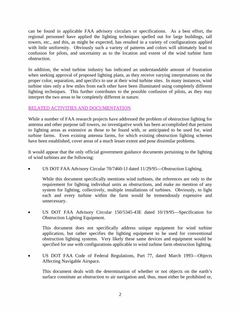
Since each wind turbine farm site was found to be unique, with regard to layout and lighting configurations used, and since in several instances more than one site was located in the same vicinity, the following are descriptions of the activities at each of the scheduled sites. SOMERSET, PENNSYLVANIA, SITE. This wind turbine farm consisted of eight Nordex N60 1300 kw wind turbine generators located in lines of four on each of two essentially parallel but staggered ridgelines. Due to the offset of the two lines, the area encompassed was roughly in the shape of a lozenge or diamond, approximately 1 mile in length and 1/4 mile in depth, as shown in figure 1. Each wind turbine had a height of 60 meters (200 feet) and a propeller radius of 30 meters (100 feet). The wind turbine units at the end of each line were obstruction lighted at the top of the generator housing with L-865 medium-intensity strobe (condenser discharge) lights for daytime use and L-864 flashing incandescent red lights for nighttime use. The white strobe effective intensity was 20,000 candelas, and the red flashing light intensity was 2,000 candelas.
The night flight was launched well after sunset and included visual approaches, at approximately 600-700 feet above the turbines, to and around both the Green Mountain site and an adjacent wind turbine facility. Emphasis was placed on evaluating the Green Mountain obstruction
5
lighting system, which consisted of only the L-864 flashing red obstruction lights. It appeared that the adjacent site was equipped with virtually the same type of flashing red obstruction lights. The weather was clear and visibility was greater than 10 miles.
FIGURE 1. GREEN MOUNTAIN SITE, SOMERSET, PENNSYLVANIA
The red obstruction lights were clearly visible from immediately after takeoff, a distance of approximately 11 miles, but were not readily identifiable as defining the limits of a wind turbine farm. Due to the random flashing (unsynchronized) nature of the obstruction lights, they could have been any group of light sources, looking particularly like a number of red stoplights on roads in the surrounding area. This effect was noted while viewing both wind turbine sites. During subsequent low-level orbits around the Green Mountain facility, the team observed a momentary occurrence of all four light synchronizations. It was immediately apparent that synchronization of the obstruction lighting array increased the effectiveness of the lighting installation immeasurably and provided significantly improved information concerning the shape and extent of the wind turbine farm as an entity. Synchronization of the strobe lights during the day is probably not essential, but would be relatively easy to add after the red beacons are installed. Masking of the obstruction lights by the rotating blades did not appear to be a problem because it only occurred at extremely limited viewing angles, and the lights were not obscured for more than a moment. Occasionally, the lights would appear as two short flashes, due to blade passage, but this again only occurred momentarily and had virtually no effect on the overall lighting effectiveness.
6

With a separation of approximately 1/2 mile between the random flashing lights, the lights at either end of the configuration were not intuitively perceived as being part of the overall wind turbine farm configuration. It may have been that synchronization of the lights would have resulted in a much better definition of the ground limits of the installation. However, the extremely short duration of the aforementioned fortuitous total synchronization of all four red lamps made it impossible to judge whether or not that would be the case. It seemed likely that obstruction lighting separations of greater than 1/2 mile would be excessive. Concerning the intensity of both the red flashing and strobe beacons, it appeared that the chosen levels were adequate, as specified in AC 150/5345-43E. CLEAR LAKE, IOWA, SITE. This wind farm consisted of 55 wind turbines, each were 187 feet to the hub and had 80-foot three-bladed rotors. Obstruction lighting consisted of standard FAA L-810 steady-burning red lights using 69-watt, 120-volt lamps. The physical layout of the wind turbine farm was essentially square, with random clusters of three or four wind turbines oriented in predominantly east to west lines. The total area of the wind turbine farm was approximately 2 square miles (see figure 2). This could be considered a relatively small installation.
FIGURE 2. CLEAR LAKE SITE, CLEAR LAKE, IOWA
While making arrangements for the aircraft rental, the airport fixed base operator mentioned the existence of an additional larger, well lighted, wind turbine farm in the immediate vicinity. This facility was inspected as well.
A ground inspection of this additional installation, known as the Top-of-Iowa wind turbine farm, was conducted during the early afternoon. This added site included a total of 89 individual wind turbines, each were 240 feet to the hub and had 87-foot three-bladed rotors.
7
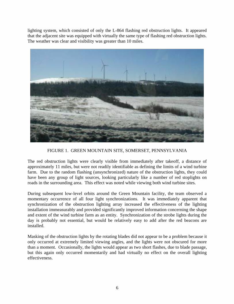
Approximately half of the wind turbines were equipped with 400-watt L-864 flashing red lights for nighttime obstruction identification, while the remaining half had 40-watt L-810 red steady-burning lights. Six wind turbines along the edge of the installation were equipped with L-864/L-865 dual red/white flashing lights to provide a measure of daytime high-intensity obstruction identification. The physical layout of the farm was essentially that of a reversed C configuration, facing west and extending for approximately 5 miles north to south and approximately 2 1/2 miles from east to west (see figure 3).
FIGURE 3. TOP-OF-IOWA SITE, JOICE, IOWA The daytime evaluation flight was completed and the daytime strobe and flashing white light installations were observed, which were relatively ineffective under the extremely bright sunlight conditions. Since the wind turbines themselves were relatively large structures and painted bright white, there was no trouble identifying them as ground obstructions from a considerable distance. The wind turbines are quite visible against any background during the daytime; therefore, strobe obstruction lighting seemed less critical. This might not be the case during daytime low-visibility weather, however, when contrast of the white structure with background fog may be minimal.
The more important night flight was conducted under clear weather conditions, with visibility greater than 10 miles. The steady-burning L-810 red obstruction lights of the Clear Lake farm were not readily identifiable from as close as 5 miles at an altitude of 1500 feet above ground level (AGL). They became more evident at 2 to 3 miles, but would probably not be very effective in reduced visibilities and under conditions that might foster low-altitude flying in poor weather conditions. At the altitudes flown, these L-810 lights did not adequately define the limits, or extent, of the wind turbine farm and were not, in the opinion of the participating project personnel, adequate for warning pilots of this unique and extensive type of array.
8

The appearance of the other Top-of-Iowa wind turbine farm obstruction lighting was significantly different and was readily identifiable as some sort of obstruction indication from as far away as 10 to 15 miles at an altitude of 2500 feet AGL. The mixed array of both flashing and steady-burning lights clearly indicated the extent of the entire installation and, to some extent, seemed to be an excessive number of lighted wind turbines. The flashing red light units appeared to be more effective than the steady-burning red lights, probably due to the greater 400:40 watt ratio of the two types of fixtures.
Another effect noted while flying this site was that the flashing light units were significantly more effective when viewed from the front side of the wind turbines, when the rotation of the turbine blades themselves created the flashing effect rather than the normal rise and fall in intensity due to turning the lamps on and off electrically. In other words, the physical cutoff of blade passage was much sharper, and more effective, than the more gradual pulsing of the lights simply turned off momentarily. This effect was not noted previously with the flashing light array at Somerset, probably due to the fact that the lights there appeared to be of considerably lower intensity. It is likely that flashing obstruction light units having a sharper on-off characteristic would prove more effective in this application.
MIDLAND/ODESSA, TEXAS, SITES. Activities at this location involved inspection and flight evaluation of five separate wind turbine farm installations: • King Mountain Site—14 turbines 299 ft AGL • McCamey Site—107 turbines 244 ft AGL (see figure 4) • Woodward Mountain Site—242 turbines 242 ft AGL • Southwest Mesa Site—Unknown number (100+) • Big Spring Site—46 turbines 243 and 267 ft AGL (see figure 5)
FIGURE 4. MCCAMEY SITE, MCCAMEY, TEXAS
9
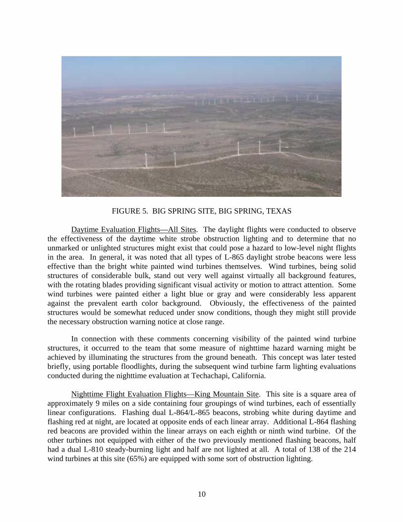
FIGURE 5. BIG SPRING SITE, BIG SPRING, TEXAS
Daytime Evaluation Flights—All Sites. The daylight flights were conducted to observe the effectiveness of the daytime white strobe obstruction lighting and to determine that no unmarked or unlighted structures might exist that could pose a hazard to low-level night flights in the area. In general, it was noted that all types of L-865 daylight strobe beacons were less effective than the bright white painted wind turbines themselves. Wind turbines, being solid structures of considerable bulk, stand out very well against virtually all background features, with the rotating blades providing significant visual activity or motion to attract attention. Some wind turbines were painted either a light blue or gray and were considerably less apparent against the prevalent earth color background. Obviously, the effectiveness of the painted structures would be somewhat reduced under snow conditions, though they might still provide the necessary obstruction warning notice at close range.
In connection with these comments concerning visibility of the painted wind turbine structures, it occurred to the team that some measure of nighttime hazard warning might be achieved by illuminating the structures from the ground beneath. This concept was later tested briefly, using portable floodlights, during the subsequent wind turbine farm lighting evaluations conducted during the nighttime evaluation at Techachapi, California.
Nighttime Flight Evaluation Flights—King Mountain Site. This site is a square area of approximately 9 miles on a side containing four groupings of wind turbines, each of essentially linear configurations. Flashing dual L-864/L-865 beacons, strobing white during daytime and flashing red at night, are located at opposite ends of each linear array. Additional L-864 flashing red beacons are provided within the linear arrays on each eighth or ninth wind turbine. Of the other turbines not equipped with either of the two previously mentioned flashing beacons, half had a dual L-810 steady-burning light and half are not lighted at all. A total of 138 of the 214 wind turbines at this site (65%) are equipped with some sort of obstruction lighting.
10

Flying approaches to this installation at night, at an altitude of approximately 1000 feet above turbine blade level, the flashing red obstruction lights were seen from a distance of approximately 10 miles. The steady-burning lights were not perceived until reaching a range of 1 or 2 miles from the site, and then only when viewed from a higher angle while overflying the installation. Team members agreed that the lower-intensity (L-810), steady-burning lights added very little to the warning capability of this obstruction lighting configuration. Further, it was felt that the higher-intensity flashing red lights (L-864) provided more than sufficient indication of an area of obstructions, but did not adequately define the extent or composition of the multiple wind turbine installations. With linear turbine orientations, such as found at the King Mountain site, synchronization of all flashing lights within each linear segment would significantly improve identification of the obstruction size and shape. With such a simultaneous flashing mode, it seems reasonable that the number of steady-burning lights required could be reduced considerably.
Nighttime Flight Evaluation—McCamey Site. This site is a rectangular area of approximately 3 by 8 miles and oriented in an east to west direction. While the site’s description was somewhat vague as to the nighttime obstruction lighting provided, it appeared that the essentially linear segments of the installation had some type of white strobe beacon at the ends of each individual string of turbines. Additional flashing red beacons (L-864) and steady-burning red lights (L-810) were provided within each linear segment, so that each and every one of the 107 wind turbine units were obstruction lighted in one manner or another.
Approaching the site from the north, it was very difficult, even at approximately 4 to 5 miles, to identify the site as a wind turbine farm. The white strobe lights, which should have been outstanding, appeared to be very weak and of an odd greenish hue. The flashing red lights were evident, but formed no definitive pattern nor provided any clue as to the obstruction size or shape. The steady-burning red lights (L-810) were extremely weak and added virtually nothing to the lighting array. If anything, the lighting of each and every turbine unit resulted in a confusing and indeterminate display that constituted one of the least impressive of all wind turbine obstruction lighting presentations evaluated thus far.
Nighttime Flight Evaluation—Woodward Mountain Site. This large (242 unit) wind turbine farm is, once again, basically linear in form and had the wind turbine segments oriented along ridgelines in a southwest to northeast direction over approximately 10 miles. Nighttime obstruction lighting consisted of flashing dual (L-864/L-865) red/white beacons at the ends of turbine linear strings that, in some cases, had as many as 47 units. These same beacons, flashing red at night, (L-810) are also located within segments on each eighth or ninth unit. Of the remaining turbines not equipped with flashing red beacons, half had L-810 steady-burning lights and half were not lighted at all.
This array of obstruction lights is virtually identical to the King Mountain site, and the nighttime flight evaluation evoked very similar opinions and comments from the team. Briefly, the red flashing lights provided sufficient warning of an area of obstructions, but since they were flashing randomly, they provided very little information as to the size and nature of the hazard. The steady-burning lights added little to the presentation, since they could only be identified at very close range while overflying the site.
11

Nighttime Flight Evaluation—East Mesa Site. This wind turbine farm has only recently
been established in the near vicinity of the other three sites addressed above. No descriptive material concerning the configuration of the site or of the obstruction lighting array was available at the time of the evaluation. Project personnel conducted evaluation flights over and around the perimeter of the wind turbine site to determine if the lighting configuration differed in any way compared to the other three sites in the area. After a quick assessment, it was determined that the lighting configuration used was very similar to the other nearby wind turbine sites, and that there was nothing unique about the lighting configuration that would warrant further evaluation. Therefore, no evaluation details for this site are included in this report.
Nighttime Flight Evaluation—Big Spring Site. This relatively small site (46 wind turbines) consisted of a rectangular area of approximately 2 1/2 by 2 miles and oriented in a northwest to southeast direction. The wind turbines were located in linear configurations around the perimeter of the mesa, and the obstruction lights were arranged in a manner similar to the King and Woodward Mountain sites. This configuration included dual red/white (L-864/L-865) flashing lights at the ends of and within the wind turbine linear segments, and steady-burning red (L-810) lights on alternate wind turbine units between the flashing lights within the strings. Once again, none of the flashing lights were synchronized within the segments, but rather flashed in a random pattern.
As was the case with approaches previously made to other sites, the L-864 flashing red beacons could be seen from a distance of about 10 miles, while the steady-burning L-810 lights were perceived only from 1 to 2 miles away. During one approach, the flashing beacons at both ends of one, ten-wind turbine string were observed to flash in unison for a considerable period of time, with a single mid-section red beacon flashing alternately during the end beacon off cycle. The effect, noted immediately by the team members, was that the lights obviously defined a linear installation of obstructions and were not simply randomly oriented, lighted objects. The same occurrence of chance simultaneous flashing had been observed at another site, resulting in the same enhanced definition of obstruction pattern. The obstruction pattern was, of course, better defined once the steady-burning lights were seen, but this occurred only at close range while overflying the installation.
The terrain in the vicinity of the small mesa on which the wind turbine farm was located was such that it was possible to make low and slow approaches to portions of the installation at or below the level of the wind turbines themselves. This type of approach could not be accomplished safely at the other sites.
The first low-level approach happened to be made toward a linear segment of turbines from the upwind direction (i.e., heading directly into the face of the turbines, with the plane of blade rotation at right angles to the line of flight). It was immediately apparent that the light from the steady-burning obstruction lights was being masked by the body of the turbine head, probably due to the low projection or profile of the L-810 fixture mounted on top of the unit. Subsequent low-level passes across the front of several other turbines confirmed the masking of the L-810 lights. This effect was not noted when viewing the L-864 flashing red lights from very low levels, most likely due to the larger diameter and height of this type of fixture. The
12

negative result of having the obstruction lights mounted on top of, and to the rear of, the turbine body was only noted while passing directly in front of units at or below the level of the hub. Such low flight in close proximity to the turbine farm is surely the most critical situation however, and having any of the obstruction lights masked obviously increases the hazard.
Nighttime Flight Evaluation—Tehachapi, California, Sites. The original intent of this last evaluation effort was to flight evaluate a single wind turbine farm known as the Oak Creek site in the Tehachapi area (see figure 6). However, during the ground site visit, the Oak Creek representatives mentioned several other turbine arrays that were established immediately adjacent to the Oak Creek installation at the Tehachapi Pass. These included (1) the totally unlighted turbines belonging to the Enron Corporation, sections D&E and (2) a ridgeline set of approximately 15 wind turbines designated as section C, known as the Cameron Ridge array (see figure 7). Another group of wind turbines, consisting of approximately 50 wind turbines, was located on a lower level to the south of the Tehachapi Pass ridgeline, referred to as section B. While information concerning the obstruction lighting of the Oak Creek installation was available, very little in the way of detail on the lighting for the other (non-Oak Creek) sites was available. It should be noted, however, that all the obstruction lighting at the Tehachapi area consisted of either flashing or strobing L-865 (condenser discharge) white lights. No red obstruction lights were used anywhere within the area.
FIGURE 6. OAK CREEK, TEHACHAPI, CALIFORNIA
13

FIGURE 7. TEHACHAPI PASS, TEHACHAPI, CALIFORNIA
During general discussions, the team brought up the concept of lighting the wind turbine structures themselves, from the ground, as a possible solution. The Oak Creek representatives expressed interest and offered to set up some ground floodlighting on one particular turbine unit for later nighttime observation.
The evaluation team flew a daytime familiarization flight around the Tehachapi Pass area to observe the general layout and to note terrain and obstruction limitations in preparation for the evening evaluation flight. It was obvious that the terrain characteristics, with the turbine arrays below and along high ridgelines on either side of Tehachapi Pass, would make the nighttime flight session somewhat difficult.
The Oak Creek Energy System turbine farm consisted of approximately 30 tall (200-foot hub height) turbines arranged in essentially two linear arrays of 10 and 20 units oriented in the southwest to northeast direction along the ridgeline and separated by approximately 1 mile. None of the turbines were equipped with onboard obstruction lighting, but three metrological towers had been erected around the periphery of the somewhat oval turbine area and equipped with L-865 white strobe obstruction lighting. The flashing of these three tower lights was unsynchronized and completely random in nature. The towers were approximately 1 to 1 1/4 miles apart. Numerous other smaller wind turbine units, both operational and abandoned, were located within the same area but, being unlighted, did not significantly affect the evaluation.
During the nighttime flight, both low- and high-level approaches to, and flights over, the Oak Creek installation were conducted. Weather conditions were ideal, with relatively unlimited visibility and virtually no cloud cover. While the turbine units, being painted white, were easily perceived by moonlight, the random flashing metrological tower obstruction lighting array provided virtually no clue as to the location or extent of the wind turbine farm. The inadequacy
14

of this lighting configuration can likely be attributed to both the unsynchronized mode of operation and to the rather extreme distance between the tower-mounted strobe units.
The Cameron Ridge wind turbine array was located along a constant contour line slightly below the highest level of the ridges framing the Tehachapi Pass and consisted of approximately 10 turbine units in a linear configuration. Five of these units, at evenly spaced intervals of about 3/8 of a mile, were equipped with white L-865 flashing in unison (synchronized). This obstruction lighting array was immediately noticed when flying into the area and remained readily identifiable as a linear entity or related set of objects whenever viewed. This characteristic would seem to be essential for any lighting array intended to warn of a multiple object or widely dispersed hazard.
The third lighted grouping of wind turbines, section B, was located on the lowest level and arranged in a rather symmetrical array of regimented lines. Unsynchronized flashing white obstruction lights mounted on the turbine units were interspersed within the installation, apparently at random. The overall effect was that of a rather dim flickering sea of lights, providing no clue as to what purpose they served.
During the evening just prior to the team’s departure and with the cooperation of the resident Oak Creek Energy Systems personnel, one of the 200-foot hub height wind turbines at a high point within the Oak Creek array was illuminated with three 500-watt halogen floodlights (see figure 8). The lights were located on the ground at the base of the tower and aimed upward to cover the entire height of the unit. An additional single spotlight was directed on the hub of the turbine to illuminate the rotating blades. The team then moved to a vantage point at relatively the same level but removed by about 1 mile from the lighted turbine unit. From that viewing distance of approximately 1 mile, the externally floodlighted wind turbine unit was easily seen and identified; although none of the other identical turbine units in the vicinity could be perceived at that range, even under existing moonlight conditions.
The Oak Creek personnel said that floodlighting a number of wind turbines within an extensive turbine farm installation might be aesthetically unacceptable. In addition, illuminating the tower and rotating blades would certainly attract bugs that, upon impacting the blades, could significantly reduce blade lift and rotor efficiency. Investigation of insect impact residue affect revealed that turbine efficiency can be reduced by as much as 33% at higher rotation speeds, which is a significant loss of turbine output. It should be noted that such an insect attraction problem has been noted with the use of obstruction lights mounted directly on the turbine rotor head also. This is offered as support for the concept of mounting any required obstruction lights on independent towers somewhat removed from the turbine units themselves.
15

FIGURE 8. EXTERNALLY LIT TURBINE
PRELIMINARY RECOMMENDATIONS FOR EXISTING SITE EVALUATIONS. From the foregoing results, it was concluded that any guidelines or instructions pertaining to the techniques for obstruction lighting wind turbine farm installations should take the following recommendations into consideration: 1. Not all wind turbine units within an installation or farm need to be lighted. Definition of
the periphery of the installation is essential, however, while lighting of interior wind turbines is of lesser importance unless they project above the peripheral units. This can be the case most often when higher ridges or plateaus are present within the wind turbine farm area.
2. Obstruction lights within a grouping of hazardous objects should have unlighted separations or gaps of no more than 1/4 to 1/2 mile if the integrity of the group
16
appearance is to be maintained. This is especially critical if the arrangement of objects is essentially linear, as is the case with most groupings of wind turbines.
3. Any array of flashing or pulsed obstruction lighting, intended to warn of a group of wind turbines forming an entity (i.e., a line, string, or series of units), should be synchronized to flash simultaneously. If an installation consists of a number of widespread, but obviously separated areas or entities, it is not necessary that all such areas flash synchronously.
4. Nighttime wind turbine obstruction lighting should consist of aviation red-colored lights, either flashing or steady-burning, only. Minimum intensities of 2000 candelas for nighttime red flashing or strobe lights (L-864) are required. The standard FAA L-810 steady-burning obstruction light, with an intensity of approximately 32 candelas, is of very little use.
5. Flashing or strobe white lights can be used for lighting wind turbines, although not preferred, as long as they are flashed in unison. This would eliminate the random, sometimes confusing, flashing pattern that was difficult to comprehend by the test pilots-engineers.
6. White strobe units of any type should not be used in conjunction with any type of red lights for nighttime identification of wind turbine farm components. They distract the pilot from his interpretation of the other red flashing and steady-burning obstruction lights and can cause confusion. Even support towers for meteorological devices located within the confines of the turbine farm should not be equipped with nighttime white strobe lights, but rather display flashing red lights.
7. Daytime obstruction lighting, if required, should consist of L-865 white strobe lights of the type used for tall tower lighting. Minimum intensities of 20,000 candelas during the day are required.
8. The wind turbines should be painted in bright white whenever possible, as the color itself acts as an effective daytime early warning device. Other colors that were encountered, such as light gray or blue, appeared to be significantly less effective in providing daytime warning.
9. Since the hub of the wind turbine unit is frequently as large as the nacelle (body) itself, a top-mounted obstruction light should be raised well above the surface of the nacelle and the rotor hub so that it may be easily seen from directly in front of the turbine.
FLIGHT VALIDATION OF RECOMMENDED CONFIGURATION As mentioned earlier in this report, the administrators of the new Blue Canyon Wind Turbine Farm scheduled for installation near Lawton, Oklahoma, had been monitoring the research activities closely. Recognizing an opportunity to possibly avoid later changes to any obstruction lighting configuration that they themselves might design, due to subsequent FAA promulgated directives, they offered to implement the recommended guidelines described above within the
17
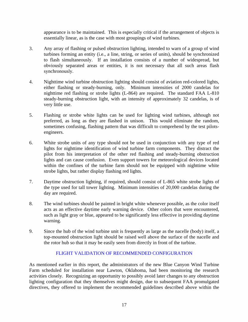
Blue Canyon Wind Turbine Farm so that researchers could validate the proposed guidelines in a real world environment. VALIDATION SITE DETAILS—LAWTON, OKLAHOMA. This site, referred to as The Blue Canyon Wind Farm Project, is located approximately 15 miles North of Lawton, Oklahoma, and on the edge of the Army’s Fort Sill installation. It is situated on ridgelines oriented essentially in an east to west direction and rising approximately 1000 feet above the surrounding flat terrain. The 45 wind turbines, comprising Phase I of an eventually much larger installation, are situated in several linear arrays along the ridgeline (see figure 9). Each turbine unit has a maximum height of 345 feet AGL, including blade length, and is capable of generating 1.65 megawatts of power at a rotor blade speed of 20 rpm.
FIGURE 9. BLUE CANYON WIND FARM LAYOUT The obstruction lighting configuration closely follows the recommended practices regarding color, intensity, and spacing. Only 14 turbines, those in the most critical locations (see figure 10), are lighted, while the remaining 31 units are not. Most importantly, all of the obstruction lights are configured to flash simultaneously. Details of the obstruction light fixtures used are as follows: • L-864 Red Flashing/Strobe Light: Peak 2000 candelas, minimum 750 candelas, with a
3° vertical beam spread
The obstruction lights are located at each end of the strings, so long as the separation between the obstruction lights is no greater than 1/2 mile. If the separation exceeds that maximum allowable distance, additional obstruction lights are spaced within the string to maintain the required 1/2-mile separation.
18

No daytime obstruction lighting is provided, since the large wind turbines are painted bright white and have, throughout the testing effort, proved to provide better warning than any lighting devices.
FIGURE 10. BLUE CANYON WIND FARM LIGHTING SCHEME
FLIGHT VALIDATION ACTIVITIES—FIRST EVALUATION. Once notice was received that the Blue Canyon Wind Farm project had been obstruction-lighted in July 2004, the team went to Lawton in August 2004 to evaluate the lighting installation. A Cessna 172 aircraft was rented for the 3-day period, but unfortunately, severe thunderstorm activity with violent turbulence made flight evaluation impossible. Instead, the day- and nighttime observations could only be made from ground and hilltop levels. GROUND OBSERVATIONS. The following quotes are from the official trip report that contained a consensus of attending personnel opinions: • Daytime—No Obstruction Lighting
“As had been observed on earlier visits to other wind turbine farms, the size and prominent location of the white painted wind turbine structures was such that they would be easily perceived and avoided by pilots transiting the area during daylight hours. Thus it was determined that no additional daytime obstruction lighting would be required as long as the structures are painted in very light colors that are contrasting to the surrounding terrain and flora.”
19

• Nighttime—Unsynchronized Mode
“Operating in the non-synchronous mode, the obstruction lighting array presented a most confusing and unsatisfactory appearance and, in the opinion of all present, did not accomplish the objective of outlining or warning of the presence of dangerous projections (i.e. 345 foot high wind turbines) above the surface of the ridgeline. This result was expected, and was the reason why synchronization of the light flashes was added to the proposed obstruction lighting system design. Photographs and video tapes of the system were taken at that time.”
• Nighttime—Synchronized Mode
“The entire team convened at the Blue Canyon site at approximately 9:00 pm on the evening of Tuesday, August 10th, for a nighttime evaluation of the obstruction lighting system operating in the required synchronous mode. The limits of the turbine farm was immediately evident, since all 14 lighted wind turbines were defined by high intensity red strobes that were flashing simultaneously. The effect was in strong contrast to the previous night’s presentation, in that the simultaneously flashing lights very clearly defined the extent of the entire wind farm, from one end to the other, and also provided a most dramatic warning of the potential hazard. The fact that observations were being made from the ground, rather than from an aircraft, did not appear to be critical. The observers were located on a small hill very nearly at the same elevation as the wind turbine installation, and have a viewpoint very similar to that which a pilot, “scud-running” and approaching from turbine level, would have.”
FLIGHT VALIDATION ACTIVITIES—SECOND EVALUATION. After experiencing the disappointment of not being able to conduct the essential flight evaluation in August 2004, steps were taken to set up a subsequent evaluation as soon thereafter as possible. In addition, it was determined that participation by a representative of the FAA sponsoring Air Traffic Organization, ATA-400, was essential and that the final validation effort should not be conducted without an ATA-400 representative attending as an observer.
The FAA project team traveled to Lawton in December 2004 to attempt another flight evaluation to finally validate the previously arrived at conclusions and recommendations as displayed in the obstruction lighting configuration at the Blue Canyon Wind Farm site. Also attending and observing the flight activities were the following individuals:
• Mr. Bruce Beard, FAA sponsor’s representative, Air Traffic, ATA-400
• Mr. Scott Larwood, California Department of Energy representative, University of California, Davis Campus
• Mr. Willum Verkert, Orga Aviation Lighting (Lighting Equipment Manufacturer)
20

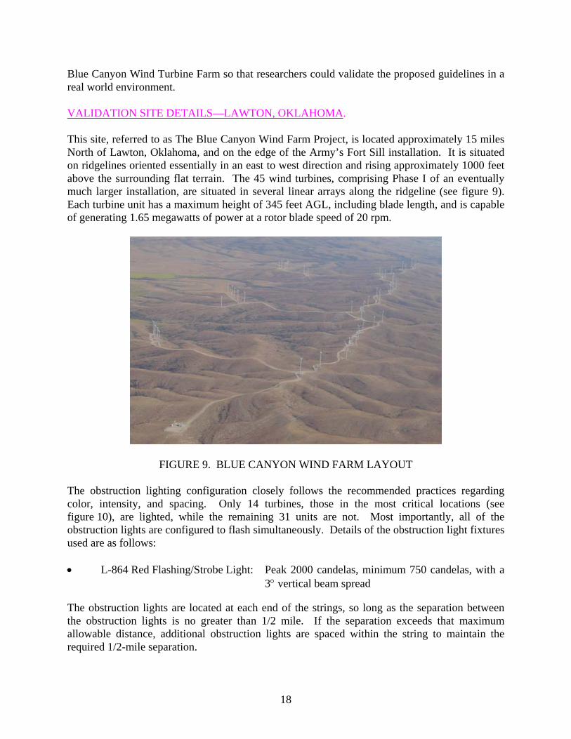
Once again using a rental Cessna 172 aircraft, multiple day and night low- and high-level approaches to the wind turbine farm were accomplished using the unsynchronized and synchronized modes of operation. Daytime observations during the most critical approach procedure, which was the aircraft flying low and nearly level with the turbines, verified that the white paint on the units made them most conspicuous in daylight against both high terrain and sky backgrounds. In the opinion of the observers, the application of light colors on the turbines made them discernable at far greater distances than the flashing (strobe) lights on other towers in the area. When approaching the ridge on which the turbines were located, the units were easily distinguished from their background at a distance of approximately 10 miles. Nighttime flights, again at high- and low-level approaches, produced the same reaction among the evaluators as the observations made from the ground during the previous visit. Unsynchronized operation presented a confused signal that an approaching pilot would not be able to distinguish as any form of identifiable obstacle. It was virtually impossible to determine the height of whatever was lighted relative to the height of the aircraft, and it even appeared that it might be possible to fly through the lighted area. Once the synchronization mode was selected, however, it was immediately evident that significant, well-outlined obstacles existed within the flight path of the aircraft. Also, the elevation of the obstacles, relative to the aircraft flight path, was easily discerned and used to decide whether the obstacles were a hazard or not. SUPPLEMENTAL METHODS TO WARN PILOTS. During this research effort, attention was made to identifying additional methods by which the flying public could be better educated about the characteristics of wind turbine farms and how their presence should be identified to the pilot. The lighting and marking presentation, which is the primary focus of this research effort, identifies only visual cues that the pilot will encounter in the field and does not provide any planning or early warning information that may be necessary to provide the highest level of safety. Many of the wind turbine farms in existence today are indicated on aeronautical charts through a variety ways. One of the more common methods, shown in figure 11, includes the placement of typical group obstruction icons, as well as a text comment that says “numerous windmills.” While this is an effective method in which to depict their location, it lacks quick recognition as to what the obstructions actually are, and it does not accurately portray any pattern or configuration that the pilot would likely be able to identify and recognize from the air. As an enhancement to the aeronautical chart, it may be feasible to identify the locations and heights of wind turbine farms through the placement of small wind-turbine-like icons on the chart, such as the icon shown in figure 12, along with a narrow line that accurately portrays an outline of the wind turbine farm. This line might be very similar to those that are used to outline a wildlife or national park area (figure 13) or those used to outline areas with obstructions such as oil fields (figure 14). In addition, in the legend of the chart (see figure 15), a small warning message should be provided citing that the actual obstruction may extend over 100 feet above the obstruction lighting fixture, and that the icons used on the chart indicate an area of
21

obstructions, not just a single, stand-alone obstruction. This could be done in the same way that guy wires are shown at the bottom of figure 15.
FIGURE 11. TYPICAL DEPICTION OF WIND TURBINE FARM ON CHART
FIGURE 12. POSSIBLE ICONS FOR INDICATING SINGLE AND MULTIPLE WIND TURBINES
22
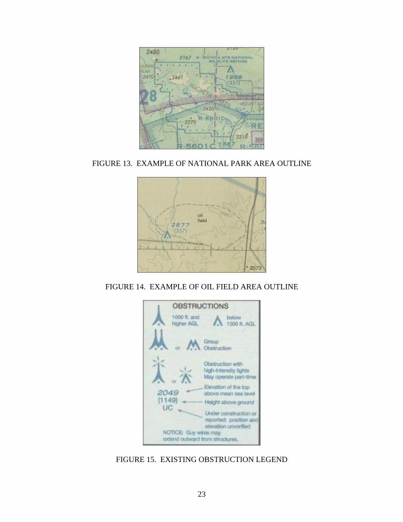
FIGURE 13. EXAMPLE OF NATIONAL PARK AREA OUTLINE
FIGURE 14. EXAMPLE OF OIL FIELD AREA OUTLINE
FIGURE 15. EXISTING OBSTRUCTION LEGEND
23

While this information falls outside the confines of this research effort, it is provided as information, and is suggested as a result of data collected via various conversations with aviation experts, international agencies, and the pilot community.
CONCLUDING REMARKS After completing the validation segment of this research effort, the following observations are offered. The red light fixtures that are programmed to flash simultaneously with each other have been determined to be the most effective and efficient technique for lighting wind turbine farms as obstructions. Of all configurations evaluated, the Blue Canyon Wind Farm array of lights and mode of operation were the most effective method of providing warning of a wind turbine farm hazard to pilots. Details of these observations are as follows: 1. Not all wind turbine units within an installation or farm need to be lighted. Definition of
the periphery of the installation is essential, however, while lighting of interior wind turbines is of lesser importance unless they project above the peripheral units. This can be the case most often when higher ridges or plateaus are present within the wind turbine farm area.
2. Obstruction lights within a group of wind turbines should have unlighted separations or gaps of no more than 1/2 mile if the integrity of the group appearance is to be maintained. This is especially critical if the arrangement of objects is essentially linear, as is the case with most wind turbine groups.
3. Any array of flashing or pulsed obstruction lighting, intended to warn of a group of wind turbines forming an entity (i.e., a line, string, or series of units), should be synchronized to flash simultaneously. If an installation consists of a number of widespread, but obviously separated areas or entities over 1 mile from each other, it is not necessary that all such areas flash synchronously.
4. Nighttime wind turbine obstruction lighting should consist of the preferred Federal Aviation Administration (FAA) L-864 aviation red-colored flashing lights. Minimum intensities of 2000 candelas for nighttime red flashing or strobe lights are required. The standard FAA L-810 steady-burning obstruction light, with an intensity of approximately 32 candelas, is of very little use.
5. White strobe fixtures (FAA L-865) may be used in lieu of the preferred L-864 red flashing lights, but must be used alone without any red lights, and must be positioned in the same manner as the red flashing lights.
24

6. The white paint most often found on wind turbine units is the most effective daytime early warning device. Other colors, such as light gray or blue, appear to be significantly less effective in providing daytime warning.
7. Daytime lighting of wind turbine farms in not required, as long at the turbine structures themselves are painted in a bright white color. If the turbines are painted with non-high-contrasting colors, such as gray or shades of gray, daytime lighting per applicable Advisory Circulars will be required.
8. Since the hub of the wind turbine unit is frequently as large as the nacelle (body) itself, a top-mounted obstruction light should be raised well above the surface of the nacelle so that it may be easily seen from directly in front of the turbine.
9. When possible, antennas or towers of heights over 200 ft that are within the turbine farm area should be incorporated into the lighting plan for the site, as they offer tall, unobstructed platforms on which lighting fixtures can be mounted and should be included in the synchronization and spacing calculations.
10. Each turbine should only require one fixture, assuming that the turbine site is manned daily, and that a failed light fixture can be replaced within the next working day. Failure to replace a failed fixture, which is essential to maintaining the 1/2-mile separation requirement, will result in an unsafe gap in the lighting configuration. If it is determined that the facility does not possess the capability to replace fixtures within the next working day, the requirement to fit each turbine with two fixtures should be explored.
11. The location of the turbine farms should be depicted on visual flight rules sectional charts in three ways. First, a general boundary line, which is used to delineate a national park or forest, that accurately portrays the layout of the turbine farm should be placed in an appropriate color. Secondly, a small icon depicting a simple wind turbine (simple tower with three small blades symmetrically placed about the top of the tower) should be placed within the boundary area, in a similar method used to depict obstructions/towers. Third, a general warning should be placed in the legend, adjacent to the definition of the wind turbine icon that states the actual obstruction may extend well over 100 feet above the warning lights. This would make sure the pilot understand that the obstruction is not limited to the position of the light fixture, but that the tips of the rotor may extend a significant distance above the light.
Based on these results, guidelines were developed to provide easy to follow directions for developing lighting plans for wind turbine facilities. These guidelines are included in appendix A.
25/26
APPENDIX A—GUIDELINES FOR DEVELOPING LIGHTING PLANS FOR WIND TURBINE FARMS
The following guidelines are provided as reference when developing obstruction lighting plans for wind turbine farms. For the purpose of this document, a turbine farm is defined as a wind turbine development area containing more than three wind turbines of heights over 200 feet. In the event a situation arises where these guidelines do not provide satisfactory safety coverage, a more conservative approach should be taken with additional lights added, if necessary, in those areas where it is needed. Aviation safety should always be the primary objective. PREFACE. The development of wind turbine farms is a very dynamic process, which constantly changes based on the differing terrain they are built on. In reviewing plans, special consideration may be made to the following: • Situations that may require additional lighting consideration:
− Proximity to airports
− Proximity to known visual flight rule routes
− Extreme terrain where the turbines vary greatly in their relative vertical position to each other.
− Proximity to areas of known flight activity, such as frequent agricultural activity. • Situations that may permit less lighting considerations:
− Extreme terrain where flight activity would be impossible to conduct in a safe manner, such as the face of a steep mountain or a very deep valley.
During the development of lighting plans for wind turbine farms, the following guidelines are provided for developing a safe, efficient lighting scheme that encompasses key safety elements identified through research. INITIAL REVIEW. Upon initial review of the proposed layout of the wind turbine farm, the arrangement of the turbines should first be identified. Primarily, there are three predominant configurations, although actual installations may contain one or any combination of the three configurations. These three configurations are linear, cluster, and grid. 1. Linear configurations are those where the turbines are placed in a line-like arrangement
along a ridgeline, the face of a mountain, or along the borders of a mesa or field. The
A-1
line may be ragged in shape or be periodically broken and may vary from just a few turbines to over 20 miles of wind turbines.
2. Cluster configurations are those where the turbines are placed in circle-like groups on top of a mesa or within a large field. A cluster is typically characterized by having a pronounced perimeter with various turbines placed inside the circle at various, erratic distances throughout the center of the circle.
3. Grid configurations are those where the turbines are arranged in a geographical shape such as a square or a rectangle, with each turbine placed a consistent distance apart in rows, giving the appearance of a square-like pattern.
It is important to identify the layout of the turbine farm first, as it provides the proper approach to be taken when identifying which turbines need to be lit. It is also at this time that any special consideration to the site’s location in proximity to airports or known corridors, as well as any special terrain considerations, be identified and addressed. LIGHTING FIXTURE AND MARKING DESCRIPTION. Research has shown that L-864 red flashing lights, in the form of incandescent or rapid discharge (strobe), are the most effective lighting devices to be used for wind turbine lighting. The second most effective light, the white L-865, is also permissible, although it is not as effective as the red L-864. The least desirable lights are the red, steady-burning L-810. Research showed that the white strobes were very distracting to pilots, due to the quick flash exposure and bright appearance. The L-810 research showed that the lights were virtually unnoticed until the aircraft was within 2 to 3 miles of the turbines.
Although it is outside of the confines of lighting standards, studies have suggested that the use of red light emitting diode or rapid discharge style L-864 fixtures are effective in reducing impacts on neighboring communities, as the fixtures’ exposure time is minimal, thus creating less of a nuisance.
While preference is shown to use red flashing lights, the selection of red or white can be made by each site developer, based on their specific application. If white is used, however, all of the other guidelines in this document should still be followed.
The key to developing a well-balanced lighting plan is to have all the light fixtures within the turbine farm flash at the same time, thus delineating the farm as one large obstruction and navigation between the turbines should be discouraged. The synchronization function can be accomplished through various means, either by radio frequency devices, hard-wired control cables, or independently mounted global positioning system synchronizer units. The site developer can decide the selection of the units, as long as the end result is that all lights flash perceivably at the same time. If the developer fails to synchronize the fixtures as suggested in this document, the developer will be required to add additional fixtures at closer spacing, as suggested in the guidelines cited in FAA Advisory Circular 70/7460-1J. The very basis of the proposed lighting standards for wind turbine sites is centered on the synchronous flashing of the perimeter lighting.
A-2

Placement of the light fixtures on the turbine nacelle should be accomplished to ensure that they are visible from 360 degrees, with particular attention being made to ensure that the hub of the turbine rotor in no way blocks the light from an aircraft approaching the windward side of the turbine at the same elevation as the turbine hub.
Daytime lighting requirements, in general, are not necessary so long as their omission would not create any known safety deficiencies. Research has shown that the turbines themselves, due to their solid (nonskeletal) construction, as well as their moving characteristics, provide sufficient warning to pilots during all daytime conditions and all documented terrain and sky conditions.
It was determined that painting or marking wind turbines with the typical checker board paint scheme is not a viable safety enhancement, as the turbines themselves provide a high level of warning with their solid (nonskeletal) construction and attention-getting rotation and movement. It should be specified, however, that the turbines be painted either bright white, or a slight shade from white, to provide the maximum daytime conspicuity. The colors gray and darker shades of white should be avoided altogether. If they have been used, the wind turbines should be supplemented with daytime lighting, as required.
TURBINE ASSIGNMENTS. The following guidelines should be followed when deciding which turbines need to be equipped with lighting fixtures. Again, the placement of the lights is contingent upon which type of configuration is being used. • Linear—A light should be placed on each turbine positioned at each end of the line or
string of turbines. From those end turbines, lights should then be positioned such that the next lit turbine is no more than 1/2 mile, or 2640 feet, from the last lit turbine. This pattern should continue until the end of the string is reached. If the last segment is significantly short, it may be practical to push the lit turbines back one or two turbines towards the starting point to present a nice, well-balanced string of lights. A high concentration of lights, in close proximity, should be avoided.
• Cluster—A starting point should be selected along the outer perimeter of the cluster. This turbine should be selected to be lit, and then, continuing along the outer perimeter of the farm, a light should be placed on the next turbine with the maximum gap between the lit turbines being no more than 1/2 mile. This pattern should continue around the perimeter of the cluster, and end at the starting point. Again, if it appears as though the lights are crowded at the ending point, the lit turbines may be pushed back by one turbine to present a balanced lighting presentation. If it is determined that the distance across the cluster is of a distance greater than 1 mile, or the terrain may vary within the cluster (+100 feet from the perimeter elevations), it may be appropriate to place a few lit turbines at strategic locations throughout the center of the cluster. This will prevent pilots from believing they may be able to climb over the outer perimeter and descend down into the center of the cluster. Again, use discretion when placing these lights to maintain a well-balanced, safe lighting configuration.
A-3

• Grid—Initially, each of the defined corners of the grid layout should be selected for lighting, and then, using the same concept of the cluster configuration, lights should be placed on turbines along the outer limits of the farm so that the maximum spacing between lit turbines is no more than 1/2 mile. If it appears as though the end of the lighting strings may be crowded, it may be necessary to move the lights back one or two turbines to create an even lighting configuration. If the grid is over 1 mile wide across the center of the group of turbines, it may be appropriate to position one or two lights within the center of the configuration to again provide warning to pilots attempting to climb over the outer limits of the grid, and descending into the center of the grid. Elevation should also be considered.
• Special Instances—On occasion, it has been documented that one or two turbines may be positioned at locations that really do not lend themselves to the linear, cluster, or grid layouts. In this event, the following guidelines should be followed. If the turbine protrudes from the general limits of the turbine farm, the turbine should automatically receive a lighting fixture. If another turbine is collocated with the first turbine, it does not require any lighting as long as it is within 500 feet from the lit turbine and not positioned on the outboard side of the lit turbine. If these requirements cannot be met, both turbines, in this case, would need to be illuminated.
SPECIAL NOTES. When conducting a review of a lighting plan for wind turbine farms, personnel are encouraged to focus on what the proposed lighting configuration will look like from an aircraft approaching the area at the same height as the turbines. If, at any time, it is thought that a pilot might be encouraged to fly into a gap in the lighting configuration, it is better to reconsider light fixture placement. Personnel are encouraged to abandon the typical aerial approach to selecting turbines to be lit, i.e., the lighting fixtures are placed according to their appearance from the prospective of an overflying aircraft. It is important to remember that these lighting guidelines were prepared for the low flying aircraft that will be flying at approximately the same elevation as the wind turbines, not over them. Careful attention needs to be made to protect the perimeter of the farm. A special note should be amended to the lighting plan stating that the developer shall notify the proper authorities if the synchronizer unit at that site fails, and the turbine farm is in a nonsynchronized state. This process shall be executed if the synchronizer is scheduled to be out of service for more than 36 hours. The process should result in the issuance of a Notice to Airman stating that there is an obstruction present with nonstandard lighting and that pilots should avoid the area.
A-4

Existing turbine farms may request permission to modify their existing lighting plans in an effort to reduce the number of lights present at the farm. In the event this occurs, the site developer should follow the proper application process and the proposed guidelines provided in this document. Turbine developers currently in the construction phase wishing to modify their lighting plans may do so, provided they follow the proper application or request modification process. Again, all guidelines in this document should be followed. Recent developments in the wind turbine industry will be bringing forth new, larger-generation turbines that will reach over 500 ft in height. The guidelines provided in this document were developed based on research that covered turbines around 400 feet in height. Caution should be exercised when adapting these lighting guidelines to wind turbine farms containing structures over 500 feet in height.
A-5/A-6