Embed Size (px)
Citation preview
UNIVERSITY OF PUNE[4363]-174
T. E. ( Electronics) Examination, May 2013 Microcontrollers (2008 Pattern)
Total No. of Questions : 12 [Total No. of Printed Pages :3][Time : 3 Hours] [Max. Marks : 100]
(1) Attempt Q.1 or Q.2, Q.3 or Q.4, Q.5 OR Q.6 From section-I(2) Attempt Q.7 or Q.8, Q.9 or Q.10, Q.11 or Q.12 from Section-
II(3) Answers to the two sections should be written in
separate answer-books.(4) Neat diagram must be drawn wherever necessary.(5) Assume suitable data, if necessary.
SECTION-IQ1.
a) Draw the architecture of 8051 Microcontroller and Explain memory mapping of 8051. [10]
b) Compare Microprocessor and Microcontroller. [6]OR
Q2.a) Explain the SFR’s of 8051microcontroller. [10]b) Compare Harvard and Van-Neumann architecture. [6]
Q3.a) Draw and explain PSW of 8051 microcontroller [8]b) Draw and explain internal structure of PORT 1 of 8051 microcontroller. [8]
OR
1
Q4.a) Write an assembly language program of 8051 to transfer 10 bytes of data
stored l in external memory location starting address 2000H to internal memory location 30H. Draw flow chart and algorithm for the same. [8]
b) Explain the following instructions with suitable example. [8]1) DA 2) MUL 3) RRC 4) JB
Q5.a) Draw an interfacing diagram of stepper with port 1 of 8051 microcontroller
and write an assembly language program to rotate stepper motor for clockwise and anticlockwise 360° rotation continuously. [9]
b) Draw interfacing diagram of 16 × 2 LCD with 8051 microcontroller, and
explain function of each pin of LCD panel. [9]OR
Q6.a) Draw and explain pin configuration of ADC 0808. [9]b) Generate a square wave with ON time of 3ms and OFF time of 10ms on all
pins of port 0. Assume crystal 22 μ F. [9]
SECTION-IIQ7.
a) Compare I2C, SPI protocol with respect to speed and hardware implementation. [8]
b) Explain RS 232 standards in detail. [8]
ORQ8.
a) Write an ALP to transfer serially ‘HELLO’ continuously with baud rate 9600. Explain how to calculate Baud rate. [8]
b) Draw an interfacing diagram of DS1307 RTC with 8051 and explain the sequence of events to sending data to DS1307 and receiving data from DS1307. [8]
2
Q9.a) Explain memory organization in PIC microcontroller. [8]b) Draw an interfacing diagram of LED with PORT B of PIC 18Fxx and write
an embedded C program for flashing of LED. [8]OR
Q10.a) Draw and explain architecture of ATMEGA 32. [10]b) Draw and explain status register of PIC microcontroller. [6]
Q11.a) Design 8051/PIC microcontrollers based system to measure and display the
temperature in Celsius with respect to time, system will take input from PT 100 sensor. Display temperature and time on LCD, use RTC DS1307 for configure time. Also display minimum temperature and maximum temperature of the day on LCD [18] Design suitable signal conditioning circuitry. Draw complete interfacing diagram using suitable ADC. Draw the flowchart and write the program in assembly or in C language which includes initialization and peripherals.
ORQ12.
a) Design 8051/PIC microcontroller based system for control of ROBOT arm in 90°clockwise direction and 90° anticlockwise direction. The direction if ROBOT arm is control by a key. Stepper motor is having teeth’s having a step angle of 1.8°. Find out the number of steps required for rotating 90°. Draw appropriate interface circuitry flow chart and write a program to drive the motor through with a delay of .5 sec (500 ms). [18]
3
UNIVERSITY OF PUNE[4363]-171
T. E. Examination - 2013FEEDBACK CONTROL SYSTEM
( 2008 Pattern)Total No. of Questions : 12 [Total No. of Printed Pages :4]
[Time : 3 Hours] [Max. Marks : 100]Instructions :
(1) Answer any three questions from section I and 3 question (2) Answers to the two sections should be written in
separate answer-books.(3) Black figures to the right indicate full marks.(4) Neat Diagrams must be drawn whenever necessary (5) Use of logarithmic tables, slide rule, Mollier
charts, electronic pocket calculator and steam tables is allowed.(6) Assume suitable data, if necessary.
SECTION-1
Q. 1. a) List and explain the advantage and disadvantage of open and closed loop control system. Give an example of each. (8)
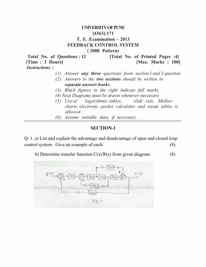
b) Determine transfer function C(s)/R(s) from given diagram. (8)
OR
Q. 2. a) Write a short note on feedback and feed forward system . (8)
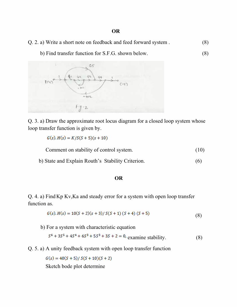
b) Find transfer function for S.F.G. shown below. (8)
Q. 3. a) Draw the approximate root locus diagram for a closed loop system whose loop transfer function is given by.
Comment on stability of control system. (10)
b) State and Explain Routh’s Stability Criterion. (6)
OR
Q. 4. a) Find Kp Kv,Ka and steady error for a system with open loop transfer function as.
(8)
b) For a system with characteristic equation
examine stability. (8)
Q. 5. a) A unity feedback system with open loop transfer function
Sketch bode plot determine
i)Gain Crossover Frequency (wgc)
ii)Phase Crossover Frequency (wpc)
iii) Gain Margin (GM)
iv) Phase Margin (PM)
Comment on stability of the system. (12)
b) State the advantage of frequency response method.. (6)
OR
Q. 6. a) explain Nyquist stability criterion based on mapping theorem (8)
b) A unit step input is applied to unity feedback control system having open loop transfer function
find the range of K for the system to be stable. (10)
SECTION-II
Q. 7. a) Obtain state model by foster’s from of a system whose T.F. is
(8)
b) Define the terms. (8)
1) State
2)State variables
3) State vector
4) State space
OR

Q. 8. a) Obtain state model of a system by cascade programming whose transfer function is
(8)
b) Write a short note on Controllability and observability (8)
Q. 9. a) Draw and explain ladder diagram for elevator system and explain it. (10)
b) Write a short note on photoelectric tachometer . state advantage. (8)
OR
Q. 10. a) Explain PI control mode, stating characteristic. (8)
b) Write a short note on (10)
1) I/O modules of PLC.
2) Functions of CPU in a processor
Q. 11. a) What is Fuzzy logic? What are linguistic variables? (8)
b) What is fuzzyfication? Which inference are used for fuzzification? (8)
OR
Q. 12. a) Explain various types of neural networks used in the control systems. (8)
b) Write a short note on Artificial Neuron (8)
Total No. of Questions : 12 [Total No. of Printed Pages :3] T.E, (Elx)
Examination - 2013 POWER ELECTRONICS (2008 Pattern)
[Time : 3 Hours] [Max. Marks : 100] Instructions :
(1) Answer 03 question from each section. (2) Answers to the 03 section I and 03 questions Section II
(3) Figures to the right indicate full marks. (4) Use of Electronic packet calculator is allowed.
(5) Neat diagrams must be drawn whenever necessary. (6) Assume suitable data, if necessary.
(7) Use of logarithmic tables slide rule, Mollier charts,
Electronic packet calculator and steam tables is allowed.
Section I
Q1. (a) What is the need of phase controller converter? Explain with circuit diagram and wave form, 3ɸ Full controlled converter with inductive load, comment on Power factor. (12) (b) A 3 phase fully controlled bridge converter is connected to a 3 phase AC supply of 400, 50Hz & operates with a firing angle of ∝= 𝜋/4. The circuit is maintaining constant current of at 10A & load Voltage is 360V. Compute. (i)Source inductance Ls. (ii) Load resistance R. (06)
OR
Q2. (a) What are the dual converters? Explain circuit diagram and wave forms working of 3ɸ dual converter with highly inductive load. (12) (b) Complete the peek value of the circulating current for 3ɸ dual converter consisting of 2,3 phase full controlled converter for the data given. Per phase supply Voltage =230V, W=315rad/sec L=12mH ∝ ₁=60°, ∝ ₂ =120° (06)
Q3. (a) What is DC to DC converter? Explain with circuit diagram & waveforms working of copper are preferred over phase controlled converters. (10) (b) Compare switched mode, liner & resonant Convert. (06)
OR
Q4. (a) What are Cycloconverter? Explain with diagram & waveforms, 3 pulse Cycloconverter. State its advantages & disadvantages. (10) (b) What is SMPS? Explain in brief. (06)
Q5. (a) What are resonant converters? Explain with circuit diagram & waveforms working of ZVS with suitable load. Comment on P.f. & state its advantages. (10) (b) What is soft start? Explain. (06)
OR
Q6. Write short notes on any three, (i) 4quadrant chopper. (ii) μP based firing circuit for triggering. (iii) 3 level inverters. (iv) MOV. (v) Field failure protection. (16)
Section II
Q7. (a) What are inverters? Explain with circuit diagram & waveforms, working 3ɸ voltage source inverter operating in 180° mode with R-load. (10) (b) A 3ɸ VSI operating in 180° mode conduction has a star connected resistive load of R=10Ω. The inverter frequency is 50Hz & DC i/p voltage is 200V. i) Determine the rms line voltage. ii) Total power in the load. (08)
Q8. (a) What is the need of cooling in industries? Suggest the remedies for reducing heating & power Dissipation in the Semi- conductor devices. (10) (b) What is auto sequential current fed PWM inverter? Explain. (08)
Q9. (a) What is electric ballast? Explain with diagram and characteristics. (08) (b) What is the difference between soldering &welding? Explain at least one type of welding techniques. (08)
OR
Q10 (a) What is HVDC? Explain with its application. (10) (b) What is CTPT? Explain. (06)

Q11. (a) What is power quality? Explain different types of power line disturbances, preventive & nullifying measurement techniques. (10) (b) What is the need of 12 pulse inverter in industry? Explain. (06)
OR
Q12. (a) What are the different types of Power factor improvement techniques in converters? Explain SAC state its advantages. (08) (b) What is the reactive power over the converter performance? (04) (c) Suggest basic design criteria for snubber circuit & its need in electronic circuits. (04)
Page 1 of 3
[Total No. of Questions: 12] [Total No. of Printed Pages: 3]
UNIVERSITY OF PUNE
[4363]-178
T. E. (Electronics) Examination - 2013
Microcomputer Based System (2008 Course)
[Time: 3 Hours] [Max. Marks: 100]
Instructions: 1 Answer 3 questions from section-I and 3 questions from
section-II 2 Answers to the two sections should be written in separate
answer-books. 3 Neat diagrams must be drawn wherever necessary. 4 Black figures to the right indicate full marks. 5 Use of logarithmic tables, slide rule, Mollier charts,
electronic pocket calculator and steam tables is allowed. 6 Assume suitable data, if necessary.
SECTION -I Q.1 A Explain the following addressing modes of 8086
processor with suitable examples. i) Register ii) Relative based indexed iii) Register Indirect iv)Immediate
8
B Explain the function of following pins of 8086 Microprocessor. i) 𝑇𝐸𝑆𝑇 ii) 𝐵𝐻𝐸 /S7 iii)𝑅𝑄/𝐺𝑇 iv) 𝐿𝑂𝐶𝐾 v) NMI
10
OR Q.2 A Explain pipelining in 8086? What is the advantage of
pipelining? 4
B What is the use of Trap flag in 8086? Explain. 4 C Draw and explain with suitable interface diagram, the
maximum mode operation of 8086 system. 10
Page 2 of 3
Q. 3 A A string of 100 bytes is stored in an array; write an
assembly language program in 8086 for sorting of ODD and EVEN numbers contained in an array. Store the ODD numbers at 2000H and EVEN at 2100H. Assume suitable segment addresses.
8
B Explain with suitable examples following instructions of 8086 microprocessor i) SCAS ii)CMPS iii)JBE iv) AAA
8
OR Q. 4 A Write a program in assembly language of 8086 to convert
a 3 digit hexadecimal number stored in register into its decimal equivalent.
8
B Explain the sequence of events that takes place in 8086 when any hardware or software interrupts arrives.
8
Q. 5 A What is paging in 80386? How paging is controlled
through control registers? 8
B What do you mean by descriptor tables? Explain how physical address is calculated using descriptors in GDT and selectors?
8
OR Q. 6 A Draw and explain the register set of 80386 and explain in
brief a typical function of each of the registers. 8
B Write a short note on protected mode and virtual mode of 80386.
8
SECTION II Q. 7 A What are various types of motherboard? Draw and
explain block diagram of IBM PC Pentium based mother board.
10
B Explain the different pins associated with USB interface. What are the different types of data transfers associated with USB?
8
OR Q. 8 A List the name of buses found on the Pentium
motherboard. Identify the high and low speed buses and explain their features them in brief.
10
B Write short notes on (any two) i) BIOS
8
Page 3 of 3
ii) PS2 port iii)Serial and parallel printer interface
Q. 9 A Draw and explain programming model of ARM 7core? 8 B Explain with suitable example the following instructions
of ARM processor. i) LDR ii) UMULL iii)B iv) SBC
8
OR Q. 10 A What are the different core extensions of the ARM
processors? How these are interpreted from the nomenclature of the ARM processor.
8
B Explain CPSR and SPSR register in ARM core. 8 Q. 11 Design 8086 based system to monitor temperature of the
water bath used in process control industry. The system will take input from the temperature sensorPT100. The output of the system is connected to the heater through relay switch. The system turns the heater ON if temperature falls below 50 degrees Celsius and turns OFF if temperature rises above 50 degree Celsius. Design suitable signal conditioning circuitry, draw complete interface diagram using 8255 of equivalent as I/O port and suitable 8bit ADC. Draw the flowchart and write the program in assembly language which initialization of the peripherals. Draw the complete interface diagram.
16
OR
Q. 12 Design 8086 processor based stepper motor control. The stepper connected to the processor through 8255 and suitable driver circuit. The motor is having a step angle of 1.8 degrees. Draw appropriate interfacing circuitry, driver circuitry, flow chart and write a program to drive the motor through 200 steps with a delay of 500 mS.
16
Page 1 of 6
[Total No. of Questions: 12] [Total No. of Printed Pages: 6]
UNIVERSITY OF PUNE
[4363]-180
T. E. (Electronics) Examination - 2013
Discrete Time Signal Processing (2008 Course)
[Time: 3 Hours] [Max. Marks: 100]
Instructions:
1 Answer ant 3 questions from each section. 2 Answer 3 questions from section-I and 3 questions from section-II.
3 Answers to the two sections should be written in separate
answer-books. 4 Neat diagrams must be drawn wherever necessary. 5 Black figures to the right indicate full marks. 6 Assume suitable data, if necessary.
SECTION -I Q.1 A Determine the output of the LTI system whose input and unit
sample response are given as follows: 𝑥 𝑛 = 𝑏𝑛𝑢 𝑛 and 𝑛 = 𝑎𝑛𝑢(𝑛)
6
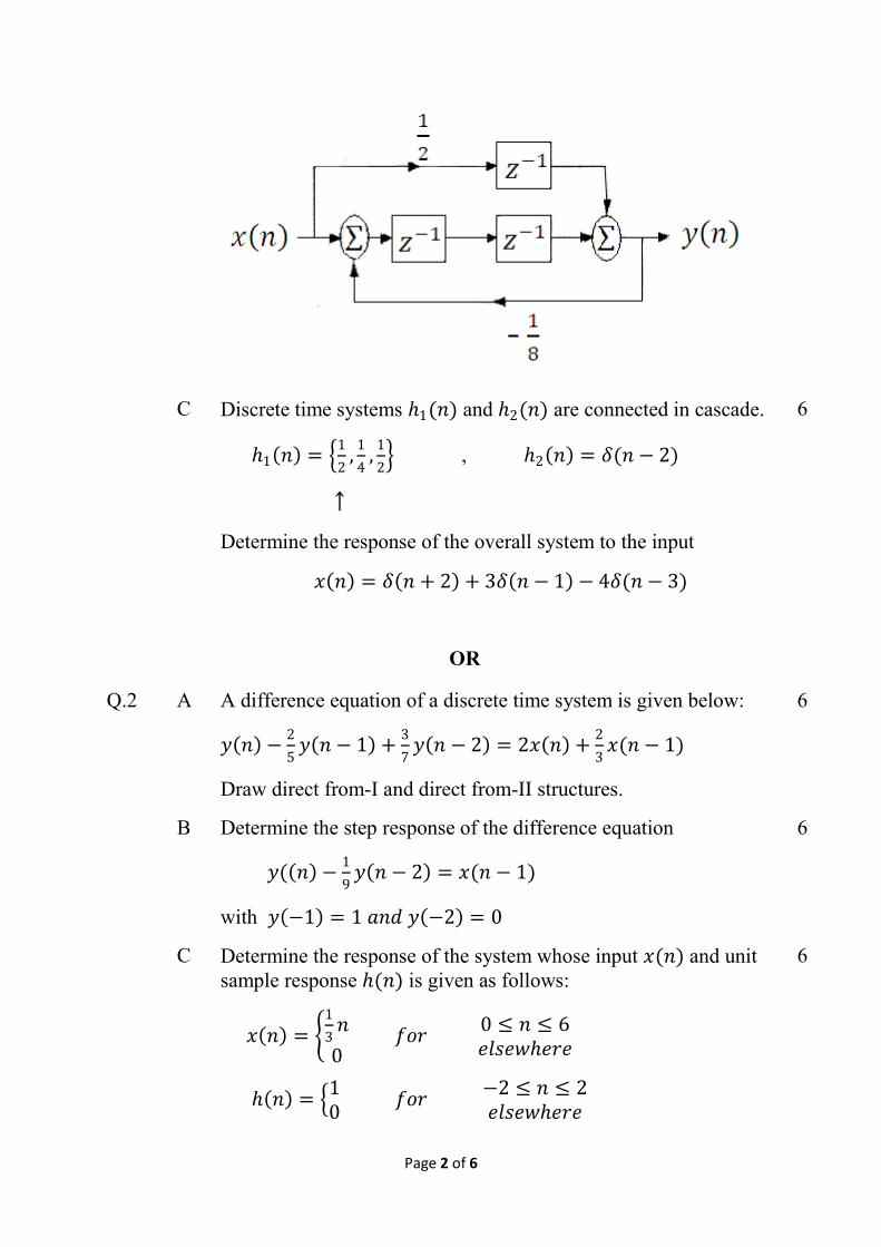
B Obtain the difference equation for the block diagram shown in figure.
6
Page 2 of 6
C Discrete time systems 1(𝑛) and 2(𝑛) are connected in cascade.
1 𝑛 = 1
2,
1
4,
1
2 , 2 𝑛 = 𝛿(𝑛 − 2)
↑
Determine the response of the overall system to the input
𝑥 𝑛 = 𝛿 𝑛 + 2 + 3𝛿 𝑛 − 1 − 4𝛿(𝑛 − 3)
6
OR
Q.2 A A difference equation of a discrete time system is given below:
𝑦 𝑛 −2
5𝑦 𝑛 − 1 +
3
7𝑦 𝑛 − 2 = 2𝑥 𝑛 +
2
3𝑥(𝑛 − 1)
Draw direct from-I and direct from-II structures.
6
B Determine the step response of the difference equation
𝑦( 𝑛 −1
9𝑦 𝑛 − 2 = 𝑥(𝑛 − 1)
with 𝑦 −1 = 1 𝑎𝑛𝑑 𝑦 −2 = 0
6
C Determine the response of the system whose input 𝑥(𝑛) and unit sample response (𝑛) is given as follows:
𝑥 𝑛 = 1
3𝑛
0 𝑓𝑜𝑟
0 ≤ 𝑛 ≤ 6𝑒𝑙𝑠𝑒𝑤𝑒𝑟𝑒
𝑛 = 10
𝑓𝑜𝑟 −2 ≤ 𝑛 ≤ 2𝑒𝑙𝑠𝑒𝑤𝑒𝑟𝑒
6
Page 3 of 6
Q. 3 A Compute the DFT of the following sequence
𝑥 𝑛 = 1,0,3,2
8
B The two sequences 𝑥1 𝑛 𝑎𝑛𝑑 𝑥2 𝑛 are given as follows:
𝑥1 𝑛 = 2,1,2,1
and ↑
𝑥2 𝑛 = 1,2,3,4
↑
Find out the sequences𝑥3(𝑚) which is equal to circular convolution of above two sequences i.e.
𝑥3 𝑚 = 𝑥1 𝑛 N 𝑥2(𝑛)
8
OR
Q. 4 A 𝐺(𝑘) and 𝐻(𝑘) are 6-point DFTs of sequences 𝑔(𝑛) and (𝑛) respectively. The DGT 𝐺(𝑘) is given as,
𝐺 𝑘 = 1 + 𝑗,−2.1 + 𝑗3.2,−1.2 − 𝑗2.4 , 0, 0.9 + 𝑗3.1,−0.3 + 𝑗1.1
The sequences 𝑔(𝑛) and (𝑛) are related by the circular time shift as,
𝑛 = 𝑔( 𝑛 − 4 )6
Determine 𝐻(𝑘) without computing the DFT.
8
B Prove that
𝑖) 𝑊𝑁𝑘+𝑁 = 𝑊𝑁
𝑘 ii) 𝑊𝑁
𝑘+𝑁
2 = −𝑊𝑁𝐾
iii) 𝑊𝑁2 = 𝑊𝑁
2
8
Q. 5 A Determine inverse Z transform of 8
Page 4 of 6
𝑍 𝑧 =1
1−1.5𝑧−1+0.5𝑧−2
For i) ROC:| z|>1, ii) ROC: |z| < 0.5 and iii) ROC:0.5 <|z|<1
B Sketch the following sequences, find their z-transforms and plot their pole zero plots.
i. 𝑥 𝑛 = (1)𝑛𝑢(𝑛) ii. 𝑥 𝑛 = (−1)𝑛𝑢(𝑛)
8
OR
Q. 6 A A discrete time causal system has a transfer 𝐻(𝑧) as,
𝐻 𝑧 =1−𝑧−1
1−0.2𝑧−1−0.15𝑧−2
i. Determine the difference equation of the system ii. Show pole zero diagram and hence find magnitude at
𝜔 = 0𝑎𝑛𝑑 𝜔 = 𝜋 iii. Find impulse response of the system.
8
B Determine the impulse response (𝑛) for a system specified by the equation
𝑦 𝑛 − 0.6𝑦 𝑛 − 1 − 0.16𝑦 𝑛 − 2 = 5𝑥(𝑛)
Assume h(0) = 5 and h(1) = 3
8
SECTION II
Q. 7 A Realize a linear phase FIR filter with the following impulse response. Give necessary equations.
𝑛 = 𝛿 𝑛 +3
7𝛿 𝑛 − 1 −
5
6𝛿 𝑛 − 2 + 𝛿 𝑛 − 4 +
3
7𝛿(𝑛 − 3)
6
B If 𝐻𝑎 𝑠 =1
𝑠+1 (𝑠+2) , Find the corresponding 𝐻(𝑧) using impulse
invariance method for sampling frequency of 5 samples/sec.
6
C Write short on bilinear transformation. 6
Page 5 of 6
OR
Q. 8 A Design bandpass linear phase FIR filter having cutoff frequencies of 𝜔𝑐=1 red/sample and 𝜔𝑐=2 rad/sample Obtain the unite sample response through following window:
𝜔 𝑛 = 10
𝑓𝑜𝑟 0 ≤ 𝑛 ≤ 6𝑜𝑡𝑒𝑟𝑤𝑖𝑠𝑒
Also obtain the magnitude / frequency response.
12
B Justify the symmetry of zero locations for linear phase FIR filters. 6
Q. 9 A A signal 𝑥(𝑛) , at a sampling frequency of 2.048 kHz is to be decimated by a factor of 32 to yield a signal at sampling frequency of 64 Hz. The signal band of interest extends from 0 to 30 Hz. The anti-aliasing filter should satisfy the following specifications :
Pass band deviation: 0.01
Stop band deviation: 80dB
Pass band: 0-30Hz
Stop band: 32-64Hz
The signal components in the range from 30 to 32 Hz should be protected from aliasing. Design a suitable one-stage decimator.
12
B Write short note on Hi resolution Narrowband Spectral analysis. 4
OR
Q. 10 A What is the relationship between the spectrums of input signal and output signal for sampling rate conversion by a factor I/D?
8
B For given signal 𝑥 𝑛 = sin(2𝜋𝑓0𝑛) find the output of the up-
sampler defined as, 𝑥𝑢 𝑛 = 𝑥 𝑛
3 for 12 samples and frequency
𝑓0 = 0.12
Draw input and output graphically.
8
Page 6 of 6
Q. 11 A i. Explain single Instruction Multiple Data (SIMD) technique. ii. Explain superscalar processing
8
B Explain different addressing formats for the DSP processors. 8
OR
Q. 12 A Write short notes:
i) Dedicated MAC unit ii) VLIW architecture
iii) pipelining
12
B Explain the important architectural features of a signal processor. 4
1
UNIVERSITY OF PUNE TE (Electronics) (Semester - I)
Examination - 2013 DATA COMMUNICATION (4363)- 172
(2008 COURSE) (New)
Total No. of Questions : 12 [Total No. of Printed Pages :3] [Time : 3 Hours] [Max. Marks :100]
SECTION – I
1. a) Explain various probability distribution functions [8] b) Explain following terms: [8]
i) Mean Value of Random variable ii) Power Spectral Density (PSD) iii) Correlation Functions iv) Variance of Random variable
OR
2. a) Prove that mean and variance of a continuous random variable X having Uniform Distribution in interval [a, b] are,
𝜇 = (𝑎 + 𝑏)/2 and σ2 =(a+b)2/12=(b-a)2/12 [8]
b) Show that if wide sense stationary process X(t) is passed through a LTI filter with impulse response h(t), then its output has constant mean square value [8]
3. a) Explain need of synchronizer in digital multiplexing. What is bit synchronization? Explain working of early-late bit synchronizer with neat diagram. [8] b) Plot frequency spectrum for RZ and NRZ, Unipolar and Polar format, Manchester format. [8]
OR 4. a) What is Inter Symbol Interference and Eye Pattern? Explain
interpretation of an eye pattern with neat diagram. [8] b) Draw line code formats for 10101101 for [8]
i) Unipolar RZ ii) Polar NRZ iii) Polar RZ iv) Manchester v) Differential Manchester vi) AMI vii) ASI vii)Polar Quaternary
2
5. a) For a (6, 3) systematic LBC, three parity bits given as, [10] C4 = d1 + d2 , C5 = d2 + d3 , C6 = d1 + d3 , i) Determine generator matrix ii) Construct code generated by this matrix iii) Determine error capacity of the code iv) Prepare syndrome decoding table v) If received vector is 101101 and 100011, determine message
words.
b) Explain in detail Viterbi decoding algorithm with an example [8]
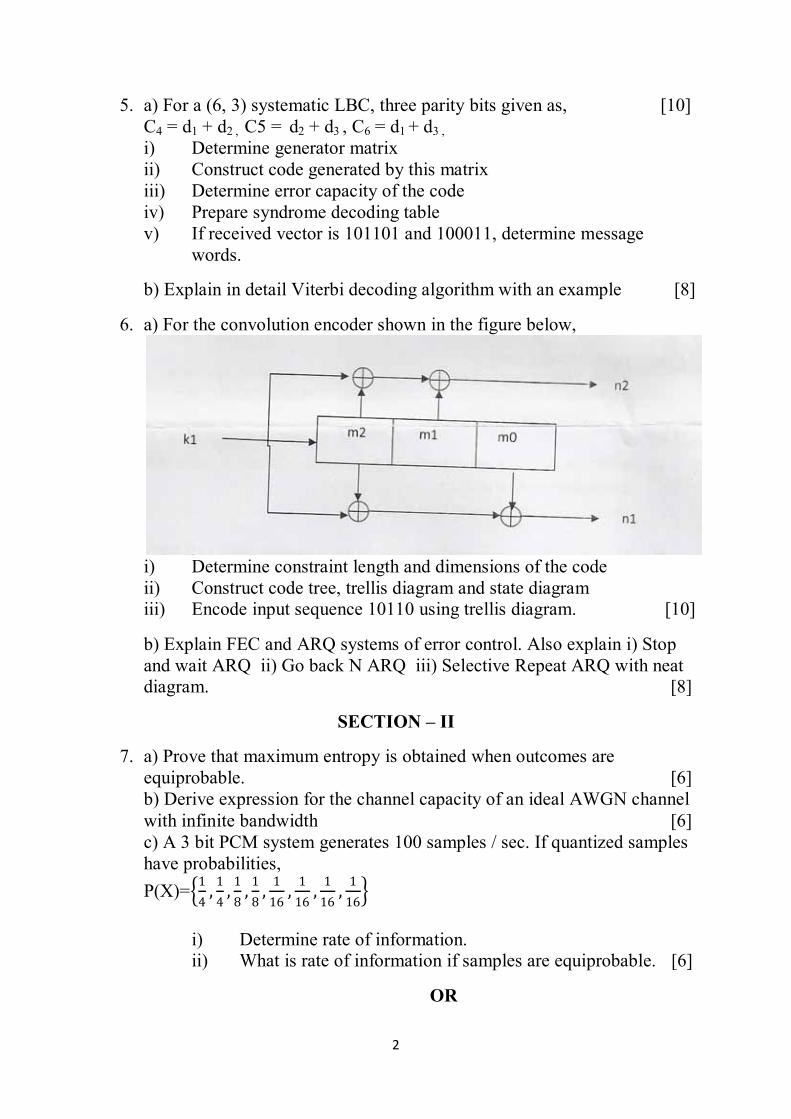
6. a) For the convolution encoder shown in the figure below,
i) Determine constraint length and dimensions of the code ii) Construct code tree, trellis diagram and state diagram iii) Encode input sequence 10110 using trellis diagram. [10]
b) Explain FEC and ARQ systems of error control. Also explain i) Stop and wait ARQ ii) Go back N ARQ iii) Selective Repeat ARQ with neat diagram. [8]
SECTION – II
7. a) Prove that maximum entropy is obtained when outcomes are equiprobable. [6] b) Derive expression for the channel capacity of an ideal AWGN channel with infinite bandwidth [6] c) A 3 bit PCM system generates 100 samples / sec. If quantized samples have probabilities, P(X)= 1
4,1
4,1
8,1
8,1
16,1
16,1
16,1
16
i) Determine rate of information. ii) What is rate of information if samples are equiprobable. [6]
OR
3
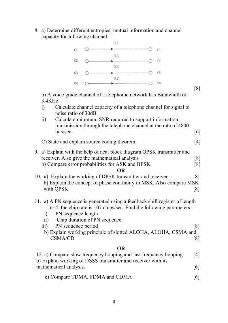
8. a) Determine different entropies, mutual information and channel capacity for following channel
[8] b) A voice grade channel of a telephonic network has Bandwidth of 3.4KHz i) Calculate channel capacity of a telephone channel for signal to
noise ratio of 30dB ii) Calculate minimum SNR required to support information
transmission through the telephone channel at the rate of 4800 bits/sec. [6]
C) State and explain source coding theorem. [4]
9. a) Explain with the help of neat block diagram QPSK transmitter and receiver. Also give the mathematical analysis [8] b) Compare error probabilities for ASK and BFSK. [8]
OR 10. a) Explain the working of DPSK transmitter and receiver [8]
b) Explain the concept of phase continuity in MSK. Also compare MSK with QPSK. [8]
11. a) A PN sequence is generated using a feedback shift register of length m=4, the chip rate is 107 chips/sec. Find the following parameters :
i) PN sequence length ii) Chip duration of PN sequence
iii) PN sequence period [8] b) Explain working principle of slotted ALOHA, ALOHA, CSMA and CSMA/CD. [8]
OR 12. a) Compare slow frequency hopping and fast frequency hopping [4] b) Explain working of DSSS transmitter and receiver with its mathematical analysis. [6]
c) Compare TDMA, FDMA and CDMA [6]
1
UNIVERSITY OF PUNE [4363]-173
T. E. (ELECTRONICS) Examination 2013 NETWORK SYNTHESIS AND FILTER DESIGN (2008 Pattern)
[Total No. of Questions:12] [Total No. of Printed pages :4]
[Time : 3 Hours] [Max. Marks : 100] Instructions :
(1) Answer any three questions from each section. (2) Answers to the two Sections should be written in separate
answer-books (3) Black figures to the right indicate full marks.
(4) Use of electronic pocket calculator is allowed. (5) Assume suitable data, if necessary.
Q.1. a) Explain necessary and sufficient conditions for positive real function. [4] Q.1.b) What is elementary synthesis procedure. Synthesize the following function by removal of poles. [8]
Z (s)= S2+1 (S2+9)
S(S2+4)
Q.1.c) Test whether the function [6]
P(s) =2s3+2s2+3s+2
s2+1 is positive real function.
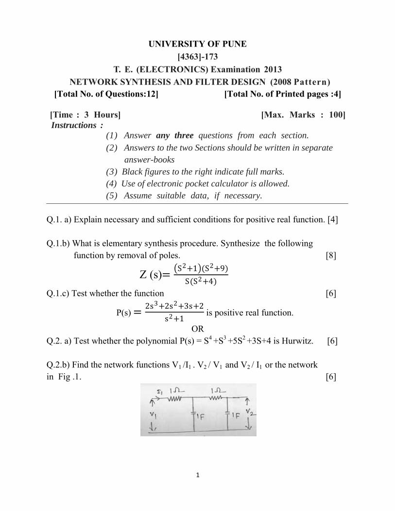
OR Q.2. a) Test whether the polynomial P(s) = S4 +S3 +5S2 +3S+4 is Hurwitz. [6] Q.2.b) Find the network functions V1 /I1 . V2 / V1 and V2 / I1 or the network in Fig .1. [6]
2
Q.2. c) Explain the significance of poles and zeros in network [6] synthesis. Also discuss the effect of poles and zeros on system function. Q.3. a) Realize Cauer forms of the following impedance function. [6]
Z(s) = 𝑥 = s2+1 (s2+3)
s s2+2 (s2+4)
Q.3.b) Obtain the Foster I and Cauer I forms of the following RC [6] impedance function.
Z(S) = S+2 (S+6)
2 S+1 (S+3)
Q.3.c) State the properties of RLC driving point function. [4] OR
Q.4.a) Obtain the Foster forms of the following RL impedance [6] function.
Z(S) = S+1 (S+4)
s+5 (s+3)
Q.4.b) Realize the RLC Impedance function. [6]
Z(S) = 𝑥 = S+3 (S+4)
s+2 (S+6)
Q.4.c)State the properties of LC impedance function. [4] Q.5. a) Explain the synthesis procedure of Z21 (S) and Y21 (S) with [6] open circuit termination. Q.5. b) State and explain significance of Zeros of Transmission [4] (ZOTs) Q.5. c) Synthesize the voltage transfer function as an all pass network [6]
G12 (S)= S2−3S+3
S2+3S+3
OR Q.6.a) For a constant resistance Lattice or Bridge T network prove [6] that ZaZb=R2
Q.6.b) Synthesize Y21 (S)=S
S3+2S2+2S+1 as a LC ladder with [6]
1𝛀 termination.
Q.6.c) Synthesize voltage ratio G12 (s) = s2+1
s2+2s+1 as a bridge [4]
T network
3
SECTION II Q.7.a)Explain the Butterworth approximation in detail and give procedure to find order of the filter. [8] Q.7.b)Butterworth responses that realizes the specification give in the normalized form The cutoff frequency fp = 1 Hz [10] The stopband frequency fs =28Hz The passband attenuation =3.01 dB The stopband attenuation Amin =60 dB Find 1) Order of Butterworth filter 2)Transfer function from the table and synthesis for it for a termination of 50 ohm 3) Actual values of components if cutoff frequency of the filter is 3104 rad/ sec.
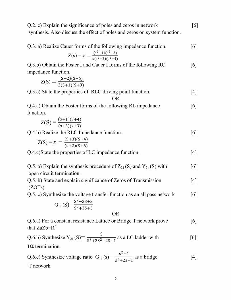
OR Q.8.a) Write a short note on [6] 1)Chebyshev Approximation. 2) Elliptic Approximation Q.8.b) What is magnitude and frequency scaling. [6] Q.8.c) Fig.2 shows a third order butterworth filter for R0 =1𝛀 and [6] Wc = 1 rad/ sec. Design a Circuit for the third order butterworth filter using frequency normalization for Wc =103 rad/ sec and R0 600
Q.9. a) Explain the different biquad topologies. [4] Q.9.b) Derive the expression for overall transfer function of [6] positive feedback topology.Write important observations on positive feedback topology. Q.9.c) Design Butterworth High pass filter at a cut-off frequency of [6] 1KHz with a pass band gain of 20. Plot its frequency response.
OR
Q.10.a) What is cascade approach in a active filter synthesis? [6] Explain in brief. Write advantages of Cascade approach. Q.10.b) Design second order low Butterworth low pass filter [6]
4
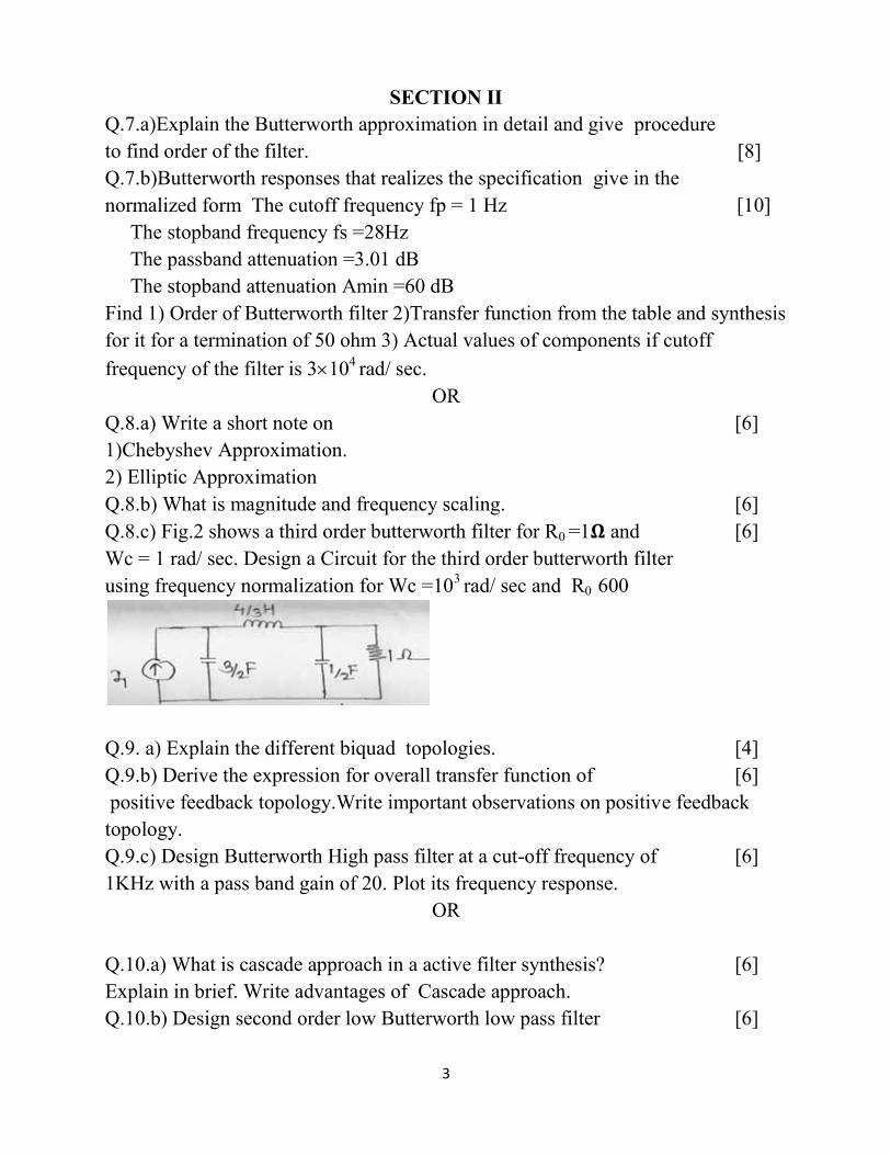
having cut off frequency of 1.5 Khz then using RC-CR transformation design high pass with same cut off frequency. Q.10.c) Compare Sallen key Butterworth and chebyshev filter [4] Q.11. a) Define sensitivity Derive the mathematical expression [8] of transfer function and perform sensitivity analysis for low pass sallen key circuit as shown in fig 3
Q.11.b) What is gain sensitivity? Derive the expression for the [8] devation in gain with simultaneous variations in all elements of second order filter network.
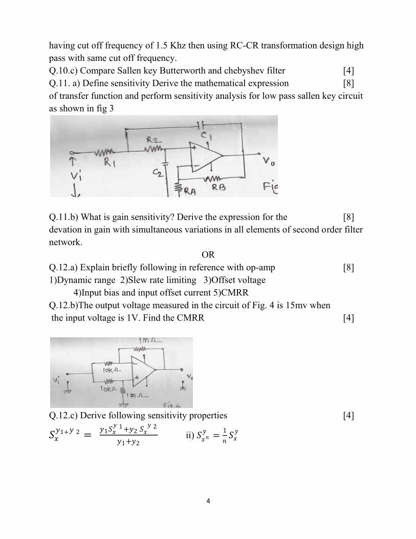
OR Q.12.a) Explain briefly following in reference with op-amp [8] 1)Dynamic range 2)Slew rate limiting 3)Offset voltage 4)Input bias and input offset current 5)CMRR Q.12.b)The output voltage measured in the circuit of Fig. 4 is 15mv when the input voltage is 1V. Find the CMRR [4]
Q.12.c) Derive following sensitivity properties [4]
𝑆𝑥𝑦1+𝑦 2 =
𝑦1𝑆𝑥𝑦 1 +𝑦2 𝑆𝑥
𝑦 2
𝑦1+𝑦2 ii) 𝑆𝑥𝑛
𝑦=
1
𝑛𝑆𝑥
𝑦
Page 1 of 3
[Total No. of Questions: 12] [Total No. of Printed Pages : 3]
UNIVERSITY OF PUNE [4363]-176
T.E. (Electronics) Examination - 2013 Drives & Control (new)
(2008 Pattern)
[Time: 3 Hours] [Max. Marks: 100]
Instructions:
1 Answer three questions from section I and three questions
from section II.
2 Answers to the two sections should be written in separate
answer-books.
3 Neat diagrams must be drawn wherever necessary.
4 Assume suitable data, if necessary.
5 Use of logarithmic tables, non programmable electronics
pocket calculator is allowed
6 Black figures to the right indicate full marks.
SECTION -I Q.1 A What are converters? Explain with circuit diagram and
waveforms working of 3 full controlled converter with highly inductive load. Deduce the equation for o/p voltage. Plot wave form for 𝛼 = 60.°
[8]
B Write short notes on four quadrant chopper drives. [6] C What is the effect of source impedance on converters [4]
OR Q.2 A What are dual converter? Explain with diagram and
wave form working of 3 dual converter with circulating current mode operation.
[8]
B The speed of a 10HP, 200 V, 1500RPM separately excited motor is controlled using a semiconverter. The rated armature current is 40 Amp. The motor parameters are Ra = 0.5 Ω, La = 10 mH, Ka f = 0.2 V/rpm. Assume that the motor current is continuous and ripple free. Find out the following at 𝛼=30.° and rated motor current and 1 230V/ 50 Hz supply (i) Motor torque (ii) Motor speed (iii)Supply power factor.
[10]
Page 2 of 3
Q.3 A What are the necessities of drive circuits in power
controller applications? Explain with diagram and waveform the working of microcontroller based control of DC drives.
[8]
B What is PLL? Explain in brief with block diagram, PLL based speed control of DC motor.
[8]
OR Q. 4 A Explain in detail the protection circuits for DC drives. [8] B Explain in detail with block diagram, close loop speed
control of DC drives. [8]
Q. 5 A What are DC to AC converters? Explain with circuit
diagram and waveforms working of 3 (transistorized) VSI with 180° conduction mode with resistance load (star conducted)
[8]
B A 4 pole 3 Induction motor drive operated from a 50 Hz 415 V supply and drawing a load torque of 100 NM. Find out the following if the motor speed is 100 rad/S. i) Motor slip (ii) The rotor power components Pag, Ploss and Pmech. (iii) The efficiency of rotor circuit.
[8]
OR Q. 6 Write short notes on
a) Effect of rotor resistance on Induction motor. b) Control strategies for speed control of Induction motor. c) Regenerative braking techniques in DC motors d) Braking of Induction motor.
[16]
SECTION II Q. 7 A Compare synchronous motor with DC and Induction
motor. [8]
B Draw and explain block diagram of self controlled synchronous motor fed from 3-phase inverter
[8]
OR Q. 8 A What is stepper motor? Explain the principle of
operation of a chopper drive (Unipolar for stepper motor)
[6]
B Draw and explain logic control circuit of a two phase control of unidirectional control of stepper motor.
[6]
C Explain different types of control of switched reluctance motor.
[4]
Page 3 of 3
Q. 9 Write short notes on (any three) a) Differences between half step and full step control of unidirectional stepper motor. b) Explain traction drive with an application of road railway. c) Neural network based PWM controller. d) Operation of a permanent magnet stepper motor
[18]
OR Q. 10 Write short notes on three
a) Neuro fuzzy system. b) Brushless DC motor c) Brushless AC motor drives. d) Power converter configurations for one phase of a switched reluctance motor.
[18]
Q. 11 A Explain the operation of fuzzy logic based wind
generation system. [8]
B Explain fuzzy logic based speed control of induction motor.
[8]
OR Q. 12 Write short notes on
a) Harmonic reduction techniques in inverters. b) Traction drive c) Explain “Tuning of a controller” for a drive system. d) Permanent magnet stepper motor
[16]
1
University of Pune T.E. (Electronics), Examination-2013
4363-177 Sensors and Interfaces (2008 Pattern)
[Total No. of Questions : 12] [Total No. of Printed Pages :2] [Time : 3 Hours] [Max. Marks : 100]
Instructions : (1) Answer 03 question from each section. (2) Answers to the two sections should be written in separate
answer-books. (3) Neat diagrams must be drawn whenever necessary.
Section I Q1. A) Explain following performance terminologies of the measurement system. [6] i) Resolution ii) Precision iii) Repeatability iv) Dead band v) Dead time vi) Accuracy B) Explain the various types of optical proximity sensors. [6] C) What are obstruction type of flow sensors? Explain working of any two. [6]
OR Q2. A) Explain the construction and working of absolute position encoder. [6] B) Explain principle and working of flow measurement system for solids. [6] C) What is absolute gage, biometric gage and differential gage sensors. Explain any tow types pressure sensors. [6] Q3. A) Explain V/I converter with floating and grounded load and list its applications. [8] B) Explain the passive circuits used in analog signal conditioning. [8]
OR Q4. A) Explain the importance of analog signal conditioning and explain the [8] following terms. 1. Signal level and bias changes. 2. Concept of loading B) Explain with neat diagram P/I converter and also explain its input output characteristics. [8]
2
Q5. A) Enlist different types of ADCs and explain any one. Also enlist ADCs selection factors. [8] B) Draw and explain interfacing of stepper motor with 89C51. [8]
OR Q6. A) Describe working of R-2R ladder type DAC. [8] B) Draw and explain interfacing of electromagnetic relay with 89C51. [8]
Section II
Q7. A) Explain the block diagram of data logger and make comparison between DAS and data logger. [8] B) Write short notes on: [8] i) RS232 standard ii) I2C bus
OR Q8. A) Write short note on profibus and foundation field bus. [8] B) Explain multichannel DAS and enlist its objectives and applications. [8] Q9. A) What are pneumatic actuators? Explain the power supply system for pneumatic actuators. [8] B) Explain the principle and operation of A.C motor. [8]
OR Q10. A) Explain with cylinder sequencing for pneumatic system for following: [8] i) Begin with Cylinder A to extend (a+), when fully extended start extending cylinder B (b+). ii) When B fully extended retract A (a-), when a fully retracted, retract B(b-). B) Explain the following terms related to control valve characteristics: [8] i) Linear ii) Quick opening iii) Equal percentage Q11. A) With block diagram explain PLC architecture. [6] B) Explain the PLC operating cycle. [6] C) Explain current source and current sink configuration of output channel. [6]
OR Q12. A) What are the various selection criteria of PLC? Explain them. [6] B) How is PLC advantageous over the relay system? [6] C) Explain the importance of latching done in PLC with an example. [6]
1
[Total No. of Questions: 12] [Total No. of Printed Pages: 2]
UNIVERSITY OF PUNE [4363]-179
T. E. (Electronics) Examination - 2013 Industrial Management (2008 Course)
[Time: 3 Hours] [Max. Marks: 100]
Instructions: 1 Answer Q1 or Q2, Q3 or Q4, Q5 or Q6 from Section I and Q7
or Q8, Q9 or Q10, Q11 or Q12 from Section II 2 Answers to the two sections should be written in separate
answer-books. 3 Black figures to the right indicate full marks. 4 Neat diagrams must be drawn wherever necessary.
SECTION -I Q.1 A Describe nature of planning. State importance of
planning. What are limitations of planning? 10
B Explain characteristics of Joint Stock Company. State advantages and disadvantages of Joint Stock Company.
08
OR
Q.2 A What is partner? State characteristics of partnership. Give advantages and disadvantages of partnership
10
B What is the difference between administration & management?
08
Q. 3 A Discuss GE 9 cell model (McKinsey matrix) for portfolio
analysis. 08
B Explain different generic strategies. 08 OR
Q. 4 A Discuss Ansoff model tracing analysis of strategic management.
08
B Select any one type of industry; carry out its SWOT analysis in detail? Explain the importance of SWOT analysis?
08
2
Q. 5 A What are the different tools used for measuring quality? 08 B Define Kaizen. State benefits and principles of Kaizen. 08
OR Q. 6 A Explain concept of ISO 9000 quality system. 08 B What is Pareto analysis? Discuss Pareto chart. When it is
used? 08
SECTION II Q. 7 A Explain capital structure. Discuss factors to be
considered while planning capital structure. 10
B What is Cost Benefit Analysis? Discuss limitations and applications of Cost Benefit Analysis
08
OR Q. 8 A Write note on break even analysis. Discuss assumptions
& limitations and applications of break even analysis. 10
B Explain SEBI. What are important functions and responsibilities of SEBI?
08
Q. 9 A What are the benefits of training? Explain with suitable
examples. 08
B Explain the objectives of HRM. 08 OR
Q. 10 A Explain Human Resource Information System. 08 B Explain career planning in brief. 08 Q. 11 A State goals of E-commerce. Give advantages and
disadvantages of E-commerce. State scope of E-commerce.
08
B Explain different phases of ERP implementation. Explain different components of ERP implementation.
08
OR Q. 12 A Describe C2C (Consumer to Consumer) model. State
advantages of C2C model. 08
B State phases in E-commerce. Give main activities of E-commerce.
08


![T.E. Electronics Engineeringengineeringbuddy.in/downloadpdf/syllabus/te/MU-TE-ETRX-Syllabus.pdf · [ University of Mumbai (T.E. Electronics Engineering R-2012) ] Page 2 From Dean’s](https://img.pdfslide.us/doc/110x75/5e86acec885c35433743e5f8/te-electronics-enginee-university-of-mumbai-te-electronics-engineering-r-2012.jpg)