Embed Size (px)
Citation preview
Condensersand Cooling
Towers
COMMERCIALHVAC EQUIPMENT
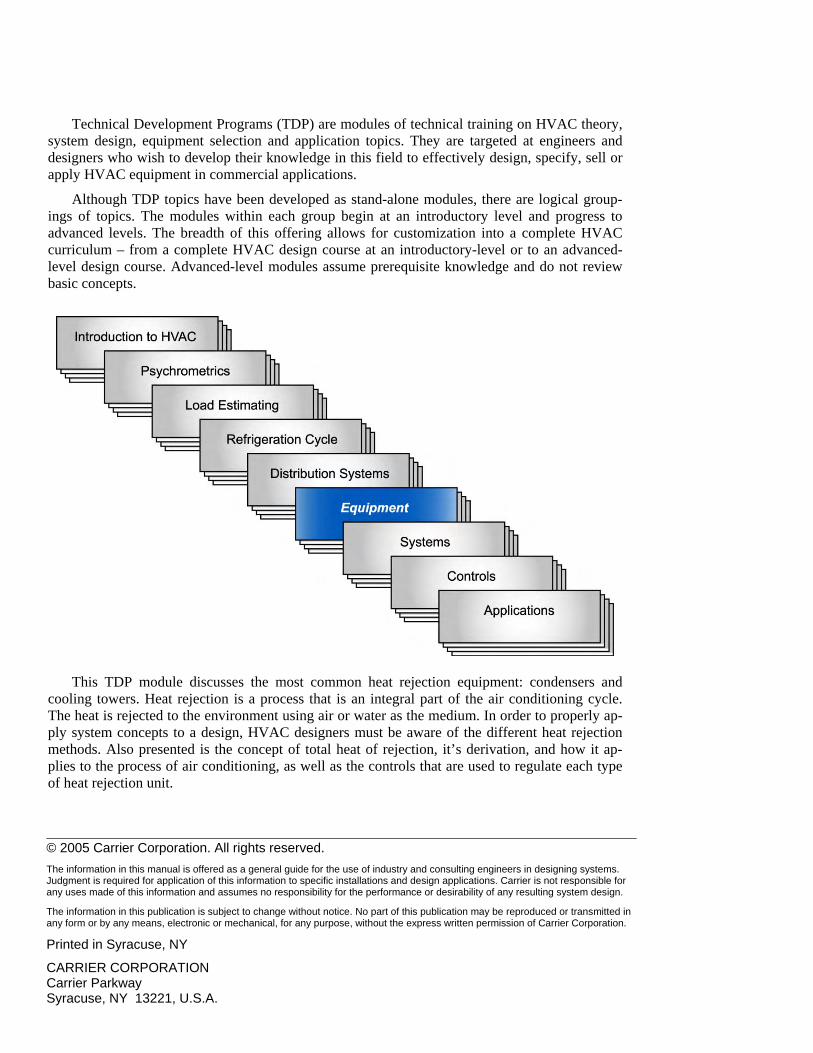
Technical Development Programs (TDP) are modules of technical training on HVAC theory, system design, equipment selection and application topics. They are targeted at engineers and designers who wish to develop their knowledge in this field to effectively design, specify, sell or apply HVAC equipment in commercial applications.
Although TDP topics have been developed as stand-alone modules, there are logical group-ings of topics. The modules within each group begin at an introductory level and progress to advanced levels. The breadth of this offering allows for customization into a complete HVAC curriculum – from a complete HVAC design course at an introductory-level or to an advanced-level design course. Advanced-level modules assume prerequisite knowledge and do not review basic concepts.
This TDP module discusses the most common heat rejection equipment: condensers and cooling towers. Heat rejection is a process that is an integral part of the air conditioning cycle. The heat is rejected to the environment using air or water as the medium. In order to properly ap-ply system concepts to a design, HVAC designers must be aware of the different heat rejection methods. Also presented is the concept of total heat of rejection, it’s derivation, and how it ap-plies to the process of air conditioning, as well as the controls that are used to regulate each type of heat rejection unit.
© 2005 Carrier Corporation. All rights reserved. The information in this manual is offered as a general guide for the use of industry and consulting engineers in designing systems. Judgment is required for application of this information to specific installations and design applications. Carrier is not responsible for any uses made of this information and assumes no responsibility for the performance or desirability of any resulting system design.
The information in this publication is subject to change without notice. No part of this publication may be reproduced or transmitted in any form or by any means, electronic or mechanical, for any purpose, without the express written permission of Carrier Corporation. Printed in Syracuse, NY
CARRIER CORPORATION Carrier Parkway Syracuse, NY 13221, U.S.A.
Table of Contents Introduction ..................................................................................................................................... 1 Condenser Total Heat of Rejection.................................................................................................. 2
Heat Rejection Factors................................................................................................................. 3 Condensers....................................................................................................................................... 4
Water-Cooled Condensers ........................................................................................................... 5 Once-Thru versus Recirculating .............................................................................................. 5 Water Requirement Calculation for Recirculating Systems .................................................... 6 ARI Conditions ........................................................................................................................ 7 Water Consumption and Makeup Quantity ............................................................................. 8 Construction and Types of Water-Cooled Condensers............................................................ 8 Fouling Factors ...................................................................................................................... 13 Tubing Materials.................................................................................................................... 15 Effects of Antifreeze .............................................................................................................. 15 Condenser Pass Arrangements............................................................................................... 16 Selection Inputs...................................................................................................................... 17
Air-Cooled Condensers.............................................................................................................. 17 Air-Cooled Condenser versus Air-Cooled Condensing Unit................................................. 18 Subcooling Circuit ................................................................................................................. 19 Placement............................................................................................................................... 20 Selection................................................................................................................................. 21
Evaporative Condensers............................................................................................................. 22 Evaporative Condenser Selection Parameters........................................................................ 24
Condenser Economics................................................................................................................ 25 Cooling Towers ............................................................................................................................. 27
Basic Terms ............................................................................................................................... 28 Entering Wet Bulb Temperature ............................................................................................ 28 Approach................................................................................................................................ 28 Range ..................................................................................................................................... 29 Total Heat of Rejection.......................................................................................................... 30 Drift (Windage)...................................................................................................................... 30 Evaporation............................................................................................................................ 31 Blow-down (Bleed)................................................................................................................ 31 Makeup .................................................................................................................................. 32 Cooling Tower Psychrometric Plot........................................................................................ 32
Types of Cooling Towers........................................................................................................... 33 Natural Draft (Atmospheric).................................................................................................. 33 Mechanical Draft ................................................................................................................... 34 Closed-Circuit Cooling Towers (Fluid Coolers).................................................................... 36
Application of Cooling Towers ................................................................................................. 37 Placement............................................................................................................................... 37 Effects of Reduced Cooling Tower Water Temperature........................................................ 38 Hydronic Free Cooling .......................................................................................................... 39 Cooling Tower Relief Profiles ............................................................................................... 40 Cooling Tower Differences: Electric versus Absorption Chillers ........................................ 41 Cooling Tower Selection ....................................................................................................... 43
Water Treatment ............................................................................................................................ 44
Condenser and Cooling Tower Control Systems........................................................................... 46 Water-Cooled Condensers .........................................................................................................47 Air-Cooled Condensers..............................................................................................................47
Refrigerant Side Control ........................................................................................................48 Airside Control.......................................................................................................................48
Evaporative Condensers.............................................................................................................50 Cooling Towers..........................................................................................................................51
Water Bypass of the Cooling Tower......................................................................................51 Airflow Control on Cooling Towers ......................................................................................52 Winter Operation of Cooling Towers ....................................................................................53
Summary........................................................................................................................................ 54 Work Session ................................................................................................................................. 55 Appendix........................................................................................................................................ 57
References:.................................................................................................................................57 Work Session Answers ..............................................................................................................58
CONDENSERS AND COOLING TOWERS
Commercial HVAC Equipment
1
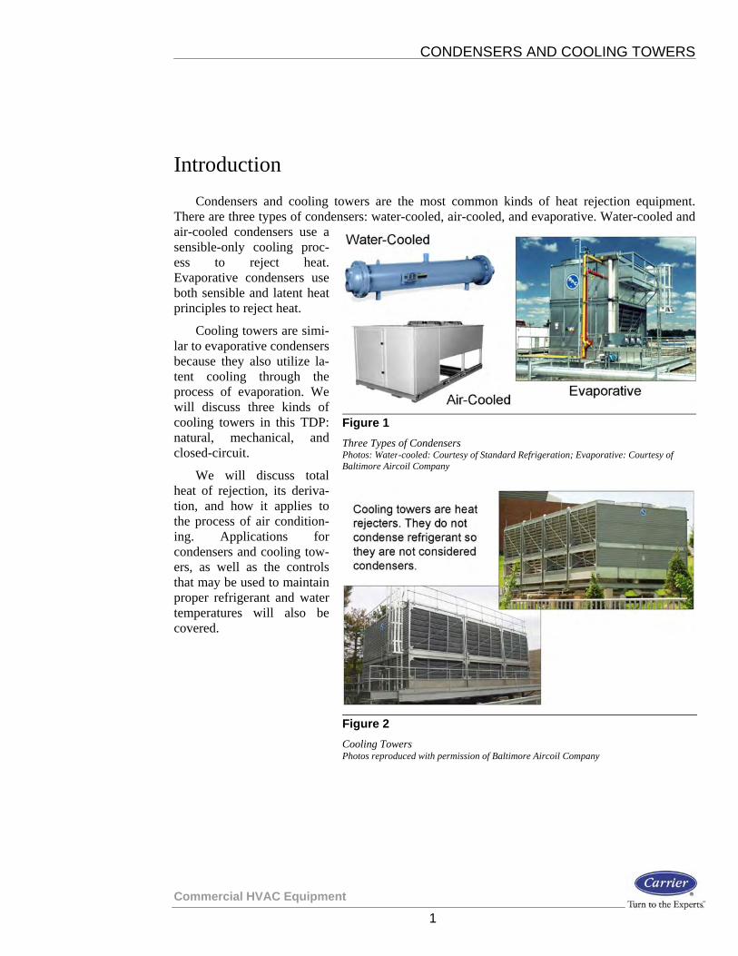
Introduction Condensers and cooling towers are the most common kinds of heat rejection equipment.
There are three types of condensers: water-cooled, air-cooled, and evaporative. Water-cooled and air-cooled condensers use a sensible-only cooling proc-ess to reject heat. Evaporative condensers use both sensible and latent heat principles to reject heat.
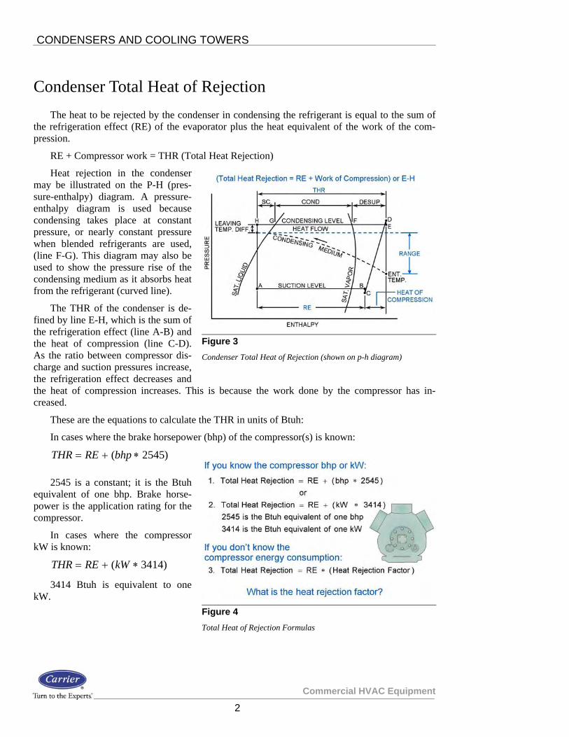
Cooling towers are simi-lar to evaporative condensers because they also utilize la-tent cooling through the process of evaporation. We will discuss three kinds of cooling towers in this TDP: natural, mechanical, and closed-circuit.
We will discuss total heat of rejection, its deriva-tion, and how it applies to the process of air condition-ing. Applications for condensers and cooling tow-ers, as well as the controls that may be used to maintain proper refrigerant and water temperatures will also be covered.
Figure 1 Three Types of Condensers Photos: Water-cooled: Courtesy of Standard Refrigeration; Evaporative: Courtesy of Baltimore Aircoil Company
Figure 2 Cooling Towers Photos reproduced with permission of Baltimore Aircoil Company
CONDENSERS AND COOLING TOWERS
Commercial HVAC Equipment
2
Condenser Total Heat of Rejection The heat to be rejected by the condenser in condensing the refrigerant is equal to the sum of
the refrigeration effect (RE) of the evaporator plus the heat equivalent of the work of the com-pression.
RE + Compressor work = THR (Total Heat Rejection)
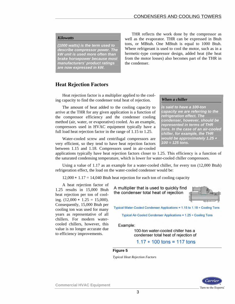
Heat rejection in the condenser may be illustrated on the P-H (pres-sure-enthalpy) diagram. A pressure-enthalpy diagram is used because condensing takes place at constant pressure, or nearly constant pressure when blended refrigerants are used, (line F-G). This diagram may also be used to show the pressure rise of the condensing medium as it absorbs heat from the refrigerant (curved line).
The THR of the condenser is de-fined by line E-H, which is the sum of the refrigeration effect (line A-B) and the heat of compression (line C-D). As the ratio between compressor dis-charge and suction pressures increase, the refrigeration effect decreases and the heat of compression increases. This is because the work done by the compressor has in-creased.
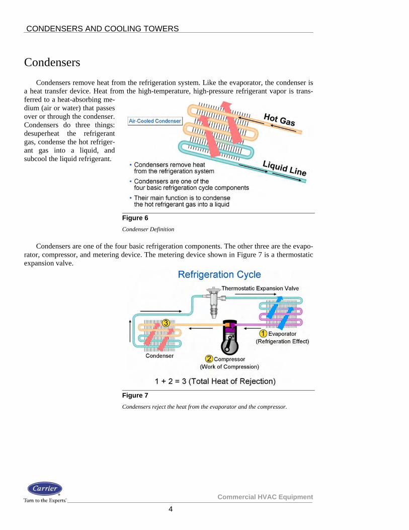
These are the equations to calculate the THR in units of Btuh:
In cases where the brake horsepower (bhp) of the compressor(s) is known:
)2545( ∗+= bhpRETHR
2545 is a constant; it is the Btuh equivalent of one bhp. Brake horse-power is the application rating for the compressor.
In cases where the compressor kW is known:
)3414( ∗+= kWRETHR
3414 Btuh is equivalent to one kW.
Figure 3 Condenser Total Heat of Rejection (shown on p-h diagram)
Figure 4 Total Heat of Rejection Formulas
CONDENSERS AND COOLING TOWERS
Commercial HVAC Equipment
3
THR reflects the work done by the compressor as well as the evaporator. THR can be expressed in Btuh tons, or MBtuh. One MBtuh is equal to 1000 Btuh. Where refrigerant is used to cool the motor, such as in a hermetic-type compressor design, added heat (the heat from the motor losses) also becomes part of the THR in the condenser.
Heat Rejection Factors
Heat rejection factor is a multiplier applied to the cool-ing capacity to find the condenser total heat of rejection.
The amount of heat added to the cooling capacity to arrive at the THR for any given application is a function of the compressor efficiency and the condenser cooling method (air, water, or evaporative) cooled. As an example, compressors used in HVAC equipment typically have a full load heat rejection factor in the range of 1.15 to 1.25.
Water-cooled screw and centrifugal compressors are very efficient, so they tend to have heat rejection factors between 1.15 and 1.18. Compressors used in air-cooled applications typically have heat rejection factors closer to 1.25. This efficiency is a function of the saturated condensing temperature, which is lower for water-cooled chiller compressors.
Using a value of 1.17 as an example for a water-cooled chiller, for every ton (12,000 Btuh) refrigeration effect, the load on the water-cooled condenser would be:
12,000 ∗ 1.17 = 14,040 Btuh heat rejection for each ton of cooling capacity
A heat rejection factor of 1.25 results in 15,000 Btuh heat rejection per ton of cool-ing. (12,000 ∗ 1.25 = 15,000). Consequently, 15,000 Btuh per cooling ton was used for many years as representative of all chillers. For modern water-cooled chillers, however, this value is no longer accurate due to efficiency improvements.
Kilowatts
(1000 watts) is the term used to describe compressor power. The kW unit is used more often than brake horsepower because most manufacturers’ product ratings are now expressed in kW.
When a chiller
is said to have a 100-ton capacity we are referring to the refrigeration effect. The condenser, however, should be represented in terms of THR tons. In the case of an air-cooled chiller, for example, the THR would be approximately 1.25 ∗ 100 = 125 tons.
Figure 5 Typical Heat Rejection Factors
CONDENSERS AND COOLING TOWERS
Commercial HVAC Equipment
4
Condensers Condensers remove heat from the refrigeration system. Like the evaporator, the condenser is
a heat transfer device. Heat from the high-temperature, high-pressure refrigerant vapor is trans-ferred to a heat-absorbing me-dium (air or water) that passes over or through the condenser. Condensers do three things: desuperheat the refrigerant gas, condense the hot refriger-ant gas into a liquid, and subcool the liquid refrigerant.
Condensers are one of the four basic refrigeration components. The other three are the evapo-rator, compressor, and metering device. The metering device shown in Figure 7 is a thermostatic expansion valve.
Figure 6 Condenser Definition
Figure 7 Condensers reject the heat from the evaporator and the compressor.


