Embed Size (px)
Citation preview
TDMA Slot Reservation in Cluster- Based VANET
Ph.D. Proposal
DEPARTMENT OF COMPUTER SCIENCE
OLD DOMINION UNIVERSITY
2011
By
Mohammad Salem Almalag
Advisor
Dr. Michele C. Weigle
Committee Members
Dr. Hussein Abdel-Wahab
Dr. Stephan Olariu
Dr. Tamer Nadeem
Dr. Dimitrie C. Popescu
CONTENTS
ABSTRACT
1. INTRODUCTION 1.1. Motivation
1.2. Objective
2. BACKGROUND and RELATED WORK 2.1. TDMA
2.2. Clustering
2.3. Cluster Formation in MANETs
2.4. Cluster Formation in VANETs
2.5. Cluster Maintenance algorithms 2.6. Cluster-based MAC
3. ARCHITECTURE 3.1 Cluster head election and cluster formation
3.2 TDMA assignment
3.3 Intra-cluster communication
3.4 Inter-cluster communication
3.5 Cluster maintenance
4. EVALUATION
5. SUMMARY
6. PLAN
7. REFERENCES
Abstract
A vehicular ad-hoc network (VANET) is an autonomous and self-configuring network of
mobile hosts connected by wireless links. It is a highly dynamic network and has harsh channel
conditions. Cluster-based MAC scheme in VANET is needed to overcome the lack of specialized
hardware for infrastructure and the mobility to support network stability and channel utilization.
This work presents a MAC algorithm for vehicular ad-hoc networks using a new method for
TDMA slot reservation under a lane-based clustering formation algorithm. Our algorithm aims to
decrease collisions and packet drops in the channel. It also will make clusters stable which will
reduce the overhead of re-clustering and lead to an efficient hierarchical network topology.
Cluster performance will be measured in terms of average clusterhead duration, average cluster
member duration, and average rate of cluster head change. The proposed algorithm is also robust
to channel error and exhibits reasonable overhead.
1. INTRODUCTION
According on the Texas Transportation Institute [35], in 2009 the cost of traffic congestion in
the US was about $115 billion. This cost based on the wasted time and fuel. The total hours
wasted in traffic congestion in the US only is about 4.8 billion hours. Moreover, about 3.9 billion
gallons of fuel is wasted in the US. Besides the economic cost, traffic congestion leads to more
pollution in our cities.
The impact of traffic congestion on the economy and the environment motivated the research
and development of Intelligent Transportation Systems (ITS). Vehicular Ad-hoc Networks
(VANETs) are important component of ITS and useful for a wide variety of applications,
including both safety applications and non-safety applications [24]. The emergence of vehicular
networking has encouraged researchers to study how such communications could be used to
enhance drivers’ comfort. In the past several years, government agencies have partnered with car
manufacturers to design and prototype different types of non-safety-related vehicular
applications. Most of these applications rely on communication in the vehicular environment.
In the US, VANETs use 75 MHz of spectrum in the 5.850 to 5.925 GHz band specially
allocated by the U.S. Federal Communications Commission for Vehicle-to-Vehicle
communication (V2V) and Vehicle-to-Infrastructure communication (V2I) using Dedicated
Short Range Communication (DSRC) technology [19]. The main goal of VANETs is to share
information such as traffic data and road conditions to increase the safety of drivers.
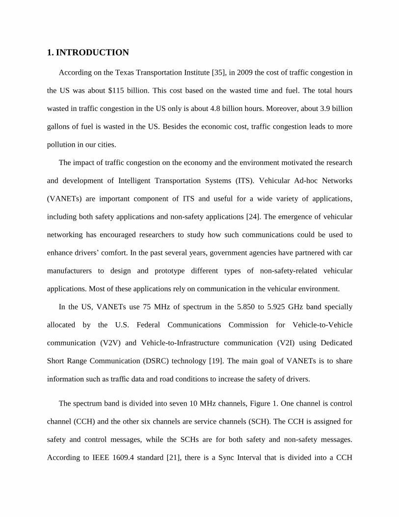
The spectrum band is divided into seven 10 MHz channels, Figure 1. One channel is control
channel (CCH) and the other six channels are service channels (SCH). The CCH is assigned for
safety and control messages, while the SCHs are for both safety and non-safety messages.
According to IEEE 1609.4 standard [21], there is a Sync Interval that is divided into a CCH
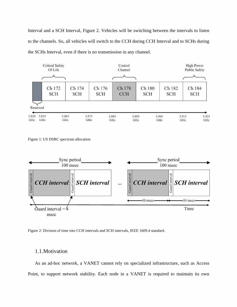
Interval and a SCH Interval, Figure 2. Vehicles will be switching between the intervals to listen
to the channels. So, all vehicles will switch to the CCH during CCH Interval and to SCHs during
the SCHs Interval, even if there is no transmission in any channel.
Figure 1: US DSRC spectrum allocation
Figure 2: Division of time into CCH intervals and SCH intervals, IEEE 1609.4 standard.
1.1. Motivation
As an ad-hoc network, a VANET cannot rely on specialized infrastructure, such as Access
Point, to support network stability. Each node in a VANET is required to maintain its own
connectivity to other nodes in the network. With the large number of nodes and the lack of
routers, a flat routing scheme, where each node acts as a router, may cause serious scalability and
hidden terminal problems. One possible solution to these problems is hierarchical clustering. In
addition, using clustering can lead to more node coordination and fewer nodes interfering with
each other.
A cluster is a group of nodes that can communicate without disconnection and that identify
themselves to be part of a cluster. These nodes select a clusterhead to coordinate the
communication among themselves. Clustering in VANETs requires selecting a clusterhead that
produce a stable cluster. Cluster stability is also affected by the dynamics of vehicles in the
cluster. New vehicles joining the cluster and other vehicles leaving the cluster are going to
change the topology of the cluster. Having a simple clustering scheme in formation and
maintaining clusters will save a significant amount of time and channel bandwidth needed to
complete this process.
Since safety applications of vehicular communication have stringent reliability and delay
requirements, giving each vehicle the time to send safety messages without interfering with other
vehicles is required. TDMA is the technique that can be used to assign a unique time slots to
each vehicle in the cluster. The goal of any assignment scheme is to make the process of
assigning slots easy and straightforward. Also, as important are the safety messages, non-safety
messages need to be delivered even if we have a lot of safety messages.
1.2. Objective
The objective of this work is to propose new media access techniques that can be used for
clustering management and communications. This protocol integrates the centralization approach
of cluster management and a new scheme for slots reservations, where cluster members are
assigned by the clusterhead to local IDs. In this technique, all vehicles are able to tune to the
Control Channel (CCH) or the Service Channels (SCHs) if needed during the time cycle. In other
words, the time cycle is not divided into two different intervals, CCH Interval and SCH Interval.
The main objective of this work is to allow vehicles to send and receive non-safety messages
without any impact on the reliability of sending and receiving safety messages even if the traffic
density is high. Interestingly, in high density traffic, non-safety activities may have to be
completely shut down [39].
In this work, we propose a dynamic TDMA slot assignment scheme for cluster-based
VANETs. In this scheme, the collision-free intra-cluster communications are managed by the
clusterhead using a TDMA scheme. As a result, we encounter three important problems. These
problems are cluster formation, cluster maintenance, and slot assignment. In this work, we
propose three algorithms to solve the addressed problems.
Thesis statement: TDMA slot reservation in cluster-based VANET will increase the
performance of delivering non-safety messages with a little impact on safety messages delivery.
This performance will measured on the type of delivery delay and reception probability of safety
and non-safety messages over the current DSRC channel switching. We also measure the
overhead by counting the extra control messages required channel assignment and cluster
maintenance.
2. BACKGROUND and RELATED WORK:
2.1. TDMA
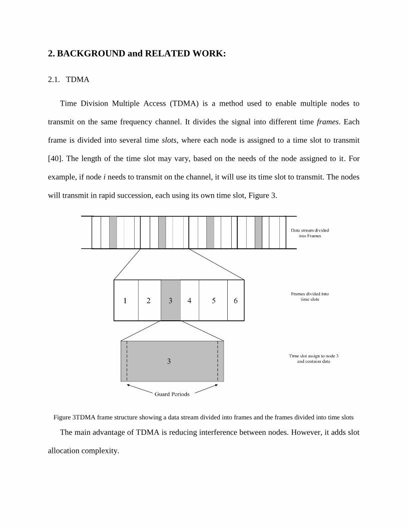
Time Division Multiple Access (TDMA) is a method used to enable multiple nodes to
transmit on the same frequency channel. It divides the signal into different time frames. Each
frame is divided into several time slots, where each node is assigned to a time slot to transmit
[40]. The length of the time slot may vary, based on the needs of the node assigned to it. For
example, if node i needs to transmit on the channel, it will use its time slot to transmit. The nodes
will transmit in rapid succession, each using its own time slot, Figure 3.
Figure 3TDMA frame structure showing a data stream divided into frames and the frames divided into time slots
The main advantage of TDMA is reducing interference between nodes. However, it adds slot
allocation complexity.
2.2. Clustering
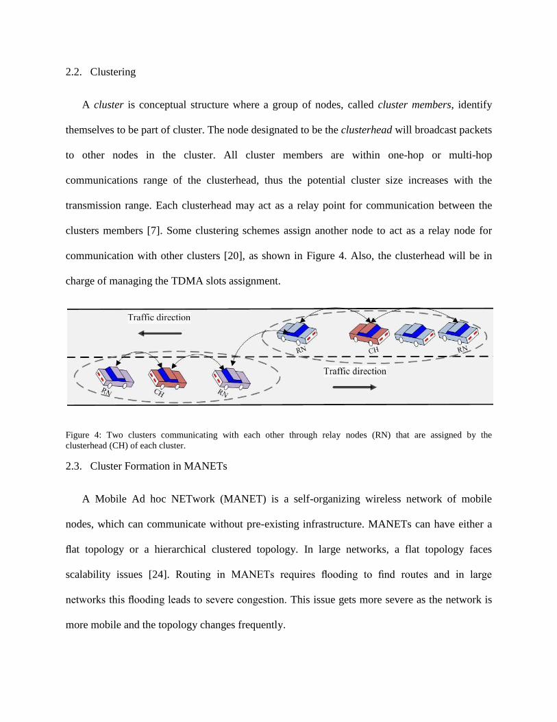
A cluster is conceptual structure where a group of nodes, called cluster members, identify
themselves to be part of cluster. The node designated to be the clusterhead will broadcast packets
to other nodes in the cluster. All cluster members are within one-hop or multi-hop
communications range of the clusterhead, thus the potential cluster size increases with the
transmission range. Each clusterhead may act as a relay point for communication between the
clusters members [7]. Some clustering schemes assign another node to act as a relay node for
communication with other clusters [20], as shown in Figure 4. Also, the clusterhead will be in
charge of managing the TDMA slots assignment.
Figure 4: Two clusters communicating with each other through relay nodes (RN) that are assigned by the
clusterhead (CH) of each cluster.
2.3. Cluster Formation in MANETs
A Mobile Ad hoc NETwork (MANET) is a self-organizing wireless network of mobile
nodes, which can communicate without pre-existing infrastructure. MANETs can have either a
flat topology or a hierarchical clustered topology. In large networks, a flat topology faces
scalability issues [24]. Routing in MANETs requires flooding to find routes and in large
networks this flooding leads to severe congestion. This issue gets more severe as the network is
more mobile and the topology changes frequently.
One of the solutions for the scalability issue in MANETs is using cluster-based approach
[25]. Clustering provide scalability by creating a backbone network of nodes. It also provides
stability for dynamic networks.
There are several algorithms for cluster formation in MANET. The main task of the cluster
formation process is to elect a clusterhead. One of the clustering algorithms is Lowest-ID. The
Lowest-ID clustering algorithm [11] is based on selecting as the clusterhead the member with the
lowest ID, assuming each node has a fixed ID. Simply, each node broadcasts its ID to other
nodes in range. When a node receives the messages from other nodes, it determines the
clusterhead as the node with the lowest ID. This algorithm is very simple and stable for general
MANET applications.
Another clustering algorithm is Highest-Degree. The Highest-Degree algorithm [16] selects
the clusterhead based on the node connectivity to the other nodes in the same cluster. Each node
knows the number of other nodes in range and then broadcasts this knowledge to the others. The
node with the maximum number of neighbors is selected as the clusterhead. This algorithm is
one of the basic techniques for clusterhead formation in MANETs.
2.4. Cluster Formation in VANETs
Several algorithms have been introduced for cluster formation in VANETs. Some of these
algorithms were first developed for MANETs. For example, Lowest-ID algorithm seems to be
simple and stable for MANET; however, this algorithm is not always stable for VANET because
the movement of the vehicles is not considered. The Highest-degree algorithm that is also not
ideal for VANETs. It is not stable for VANETs due to the nature of the nodes movement. If the
clusterhead changes its behavior at any moment, the connectivity level could change
dramatically.
To have a good VANET clustering algorithm, we have to consider the characteristics of
VANET. The Utility Function algorithm [6] is a VANET clustering algorithm that performs
better than the previous two algorithms, Lowest-ID and Highest-Degree. This algorithm is based
on a multiple-metric weighting algorithm, considering speed, velocity and position. In the
process of the clusterhead selection, the closest position to the average and the closest velocity to
the average of all proximal vehicles are calculated along with connectivity level to determine the
most stable clusterhead. Periodically, each node broadcasts its status to other nodes in range.
When the node receives this information, it starts to evaluate each node by using the utility
function. The node with the highest value is chosen to be the clusterhead. In a highway
environment, this algorithm has been shown to provide better results than the classic MANET
algorithms. It puts the position and velocity, which are major VANET characteristics, into
consideration. However, it still ignores the traffic flow on the road. For example, in an urban
scenario where are many intersections, if the clusterhead is located on the leftmost lane, it has to
turn left even if most of the vehicles are going straight. In this case, the vehicles will need to
perform the process of clusterhead selection again.
Zaydoun and Mahmud [34] proposed grouping vehicles based on the mobility patterns.
Vehicles with close speeds will be grouped together in one cluster. But this might lead to having
clusters overlap.
We introduce a new cluster formation algorithm. This scheme aims to extend the life of the
clusterhead. We take advantage of knowing the exact lane of vehicles on the road and then
broadcast this knowledge to other nearby vehicles to determine the optimal clusterhead. Our
method of selecting the clusterhead is the key to achieving a more stable cluster.
2.5. Cluster Maintenance Algorithms
Based on dynamic nature of vehicles in VANETs and the changes in the network topology,
clusters must be updated frequently to maintain the stability of the network. Cluster maintenance
is a very important process in any clustering algorithm. It will be performed more often than
cluster formation. The cluster maintenance process should be done in a manner that it does not
add much communication overhead.
A significant amount of research on cluster maintenance has been done in MANETs [36-37].
VANETs, however, have different mobility characteristics than MANET. So, applying MANTE
algorithms in VANET is not always successful. Venkataraman et al. [36] proposed a clustering
algorithm that performs formation and maintenance in MANET. In the process of maintenance,
if the clusterhead is leaving the cluster, the clusterhead selection process will be performed
again. This will consume a lot of time and channel bandwidth. It is better to do the clusterhead
changes in a way that does not require a lot communications.
In our cluster maintenance algorithm, we introduce a new cluster maintenance algorithm that
solves the issues of the network topology changes. It addresses such as new cluster member(s)
joining, current cluster member(s) leaving the cluster, clusters merging, and clusterhead
changing. All the problems mentioned are going to be solved with least amount of overhead. We
aim to design an algorithm that makes changes in the topology unseen by most of the cluster
members. For example, when the clusterhead is about to leave the cluster, it will find a stable
clusterhead candidate. Then, the current clusterhead will switch local IDs with clusterhead
candidate. After switching, a new more stable clusterhead will take over with the need of
performing the clusterhead selection process again.
2.6. Cluster-based MAC Algorithms
A significant amount of research has been spent in developing new cluster-based MAC
protocols. Cluster-based MAC protocols are presented in [26-32]. Gunter et al. [27] proposed
schemes where the clusterhead takes on a managerial role and facilitates intra-cluster
communication by providing a TDMA schedule to its cluster members. Su and Zhang [32]
proposed a scheme where adjacent clusters are assigned different CDMA codes to avoid
interference between clusters. This work shows a substantial reduction in probability of message
delivery failure, when compared to the traditional 802.11 MAC. The disadvantages of this work
are that it uses two transceivers. It also reserve channel for specific tasks; so if there is no
activities on these channels, the channels will be wasted.
Much of the recent VANET research discussing cluster-based MACs and routing
schemes also present a low-maintenance clustering algorithm. Each of these algorithms works
essentially the same way, whereby nodes periodically transmit HELLO beacons to indicate their
present state. States can be one of the following: Undecided, Clusterhead, Cluster Member, and
sometimes Gateway. An undecided node will join the first clusterhead that it hears a HELLO
beacon from (or joins all clusterheads if Gateway nodes are allowed). If the node does not hear
from a clusterhead within a given time period, it will become a clusterhead itself. In addition,
protocols are introduced to deal with colliding clusters, which occurs when two clusterheads
come within range of one another. During a cluster collision, one clusterhead decides to give up
its status to the other. This technique is used by Su and Zhang [32] and Santos and Seed [33]
without regard for mobility. Gunter et al. [27] proposed a scheme where mobility is addressed
during cluster collision, whereby the winning clusterhead is the one with both lower relative
mobility and closer proximity to its members. Alternatively, Kayis and Acarman [31] address
mobility by first classifying nodes into speed groups, such that nodes will only join a CH of
similar velocity.
3. ARCHITECTURE
3.1. Clusterhead Election and Cluster Formation
We present a lane-based clustering algorithm designed to provide stability in cluster lifetime
for vehicular ad-hoc networks (VANETs). Stable clustering methods reduce the overhead of re-
clustering and lead to an efficient hierarchical network topology. During the creation of VANET
clusters, cluster members select one member to be the clusterhead. Fewer clusterhead changes
result in a more stable cluster. To achieve this goal, cluster members must select a member that
has the potential to be a clusterhead longer than other cluster members. Our method aims to
select a clusterhead based on the lane where most of the traffic will flow.
Our proposed algorithm is based on the assumption that each vehicle knows its exact lane on
the road via a lane detection system and an in-depth digital street map that includes lane
information, such as NAVTEQs NAVSTREETS [14]. A lane detection system is an important
element of many applications in VANETs, such the Extended Emergency Brake Light system
[9].
The Global Positioning System (GPS) is the primary system that is used for vehicle
localization. However, GPS has weaknesses when it comes to updating the positioning data and
when there is no signal. GPS has a 5 m error which is larger than the distance between lanes.
There has been much research on detecting and localizing lanes on roads. Several algorithms
have been proposed using different techniques. Some methods use GPS combined with a wheel
odometer [4], which provides relative localization as it detects changes in pose relative to the
previous pose. The advantage of the wheel odometer is that it is high resolution and simple to
use. It can typically detect movements on the order of tenths of millimeters. Other algorithms do
not use GPS, and instead use techniques such as vision [2], [3], [15], LIDAR (Light Detection
and Ranging) [10] and a beacon network using infrastructure to triangulate vehicle position [13].
Here we present the three clusterhead selection algorithms that we will be comparing our
work against:
Lowest-ID: As we explained in Section2, this algorithm is very simple and stable for general
MANET applications. However, in VANETs, the lowest ID clusterhead is not always the ideal
selection because the movement of the vehicles is not considered.
Highest-Degree: As we explained in Section 2, this algorithm is one of the basic techniques
for clusterhead formation in MANETs. However, it is not stable for VANETs due to the nature
of the nodes movement. If the clusterhead changes its behavior at any moment, the connectivity
level could change dramatically.
Utility Function: As we explained in Section 2, it puts the position and velocity, which are
major VANET characteristics, into consideration. However, it still ignores the traffic flow on the
road.
In our approach, we considered urban scenarios with intersections in the design of our
proposed algorithm. The clusterhead will be selected based on the flow of the majority of traffic.
For example, if the road has four lanes and three of them are going straight, the clusterhead
should be selected from the lanes that are going straight. This research applies the knowledge of
each vehicles lane and the flow direction of each lane, Figure 5.
In urban scenarios, traffic flow splits at each intersection. There are three main traffic flows at
an intersection: Left Turn (LT), Right Turn (RT), and No Turn (NT). The intersection may have
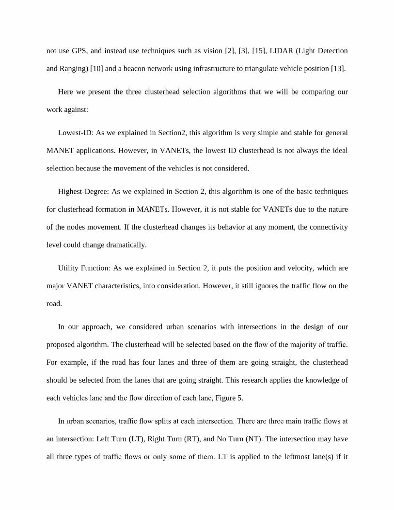
all three types of traffic flows or only some of them. LT is applied to the leftmost lane(s) if it
splits the traffic to the left, RT is applied to the rightmost lane(s) if it splits the traffic to right,
while NT is applied to the lane(s) in the middle if traffic goes straight.
Figure 5: Showing how the traffic flow is dividing vehicles ahead in different directions.
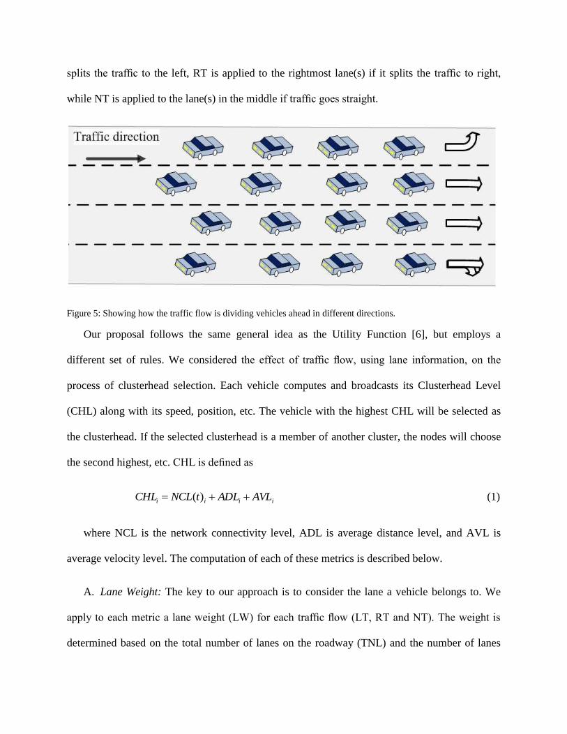
Our proposal follows the same general idea as the Utility Function [6], but employs a
different set of rules. We considered the effect of traffic flow, using lane information, on the
process of clusterhead selection. Each vehicle computes and broadcasts its Clusterhead Level
(CHL) along with its speed, position, etc. The vehicle with the highest CHL will be selected as
the clusterhead. If the selected clusterhead is a member of another cluster, the nodes will choose
the second highest, etc. CHL is defined as
iiii AVLADLtNCLCHL )( (1)
where NCL is the network connectivity level, ADL is average distance level, and AVL is
average velocity level. The computation of each of these metrics is described below.
A. Lane Weight: The key to our approach is to consider the lane a vehicle belongs to. We
apply to each metric a lane weight (LW) for each traffic flow (LT, RT and NT). The weight is
determined based on the total number of lanes on the roadway (TNL) and the number of lanes
for each traffic flow (NLTF). If the road has three different traffic flows, we will have three
different LWs. LW is defined as
kk NLTFTNL
LW 1
(2)
where k is the lane number. For example, if we have a road of four lanes where one lane is
LT, one lane is RT, and two lanes are NT, then the LW for each traffic flow will be LTLW = RTLW
= 0.25 and NTLW = 0.50. If a vehicle is on a lane with traffic flow LT, then it will use LTLW . In
the equations that follow, TFLW represents the LW for the traffic flow of the vehicle performing
the computation.
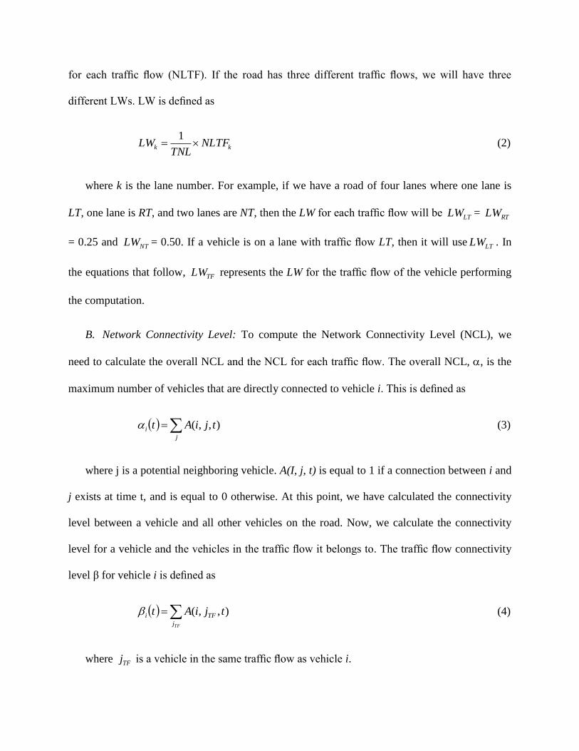
B. Network Connectivity Level: To compute the Network Connectivity Level (NCL), we
need to calculate the overall NCL and the NCL for each traffic flow. The overall NCL, , is the
maximum number of vehicles that are directly connected to vehicle i. This is defined as
j
i tjiAt ),,( (3)
where j is a potential neighboring vehicle. A(I, j, t) is equal to 1 if a connection between i and
j exists at time t, and is equal to 0 otherwise. At this point, we have calculated the connectivity
level between a vehicle and all other vehicles on the road. Now, we calculate the connectivity
level for a vehicle and the vehicles in the traffic flow it belongs to. The traffic flow connectivity
level β for vehicle i is defined as
TFj
TFi tjiAt ),,( (4)
where TFj is a vehicle in the same traffic flow as vehicle i.
After calculating both levels of network connectivity, we define the total connectivity level
for vehicle i on a lane belonging to traffic flow TF as
TFiii LWtttNCL )( (5)
where TFLW is the lane weight for the lane that vehicle i occupies.
C. Average Distance Level: To calculate the Average Distance Level (ADL), we calculate
the overall average absolute distance, i , between vehicles that are directly connected to vehicle
i. This is defined as
NV
yyxxj
ijij
i
22 )()(
(6)
where j is any vehicle connected to i, and NV is the total number of vehicles that are directly
connected to i in any lane.
Next, we calculate the average absolute distance, i , between vehicle i and other vehicles in
the same traffic flow, TF. This is defined as
TF
j
ijij
iNV
yyxxTF
22 )()(
(7)
where j is any vehicle in the same traffic flow and connected directly to i, and TFNV is the
total number of vehicles that are directly connected to i and in the same traffic flow.
The ADL for vehicle i in traffic flow TF is defined as
TFiii LWADL (8)
D. Average Velocity Level: We calculated the overall Average Velocity Level (AVL) as the
difference between the average velocities of all vehicles in range and the candidate clusterhead
velocity. Then, we add this to the product of LW and the average velocity for the traffic flow. The
overall AVL, i , for vehicle i is defined as
j
jii VelVel (9)
where j is a potential neighboring vehicle, and iVel is the velocity of vehicle i.
Now, we calculate the AVL, i , for vehicle i and the traffic flow it belongs to. This is
defined as
TFj
jii VelVel (10)
where TFj is a vehicle in the same traffic flow as vehicle i.
The AVL for vehicle i in traffic flow TF is defined as
TFiii LWAVL (11)
3.2. TDMA assignment
The presentation of our scheme involves several aspects of intra- and inter-cluster
communication. In turns, each of these communication regimens is partitioned into cases
depending on whether or not the cluster is single-hop. The clustering scheme we are using is
clusterhead based, where the consensus is dictated by the clusterhead (CH). We also assume that
all vehicles are equipped with GPS to ensure that vehicles have synchronized clocks.
To explain our scheme, we assume an N-car cluster where the cars are synchronous. The
transmission time is partitioned into consecutive, non-overlapping logical TDMA frames. We
assume the existence of k slotted service frequency channels (channels, for short) numbered from
0 through k-1. In each channel, the logical TDMA frames are aligned, i.e. begin and end at the
same time. Each logical frame contains 𝑁
𝑘 + 1 slots numbered from 0 through
𝑁
𝑘 . Also, all
slots are the same size; the slot size τ, is known to all vehicles in the cluster. We also assume one
narrow-band control channel − channel k − used by the vehicles and CH for disseminating status
and/or control messages; we anticipate the size of a mini-slot to be sufficient to allow individual
vehicles to communicate their status information. By virtue of synchronization, the vehicles
should know frame and slot boundaries. The number of vehicles (N) may change dynamically;
and the CH is responsible for updating N and for informing all vehicles in the cluster of the new
value of N. N, k and τ are technology-dependent. We anticipate:
o N to be at most 64
o k to be around 6
o τ to be about 6ms, the time to send a non-safety message (i.e., about 1500 bytes)
o a mini-slot on the control channel to contain at least 64 bytes; (i.e. assuming k=6,
this implies a slot size of 384 bytes)
Each vehicle in the cluster will receive a local ID. This local ID is a number from 0 to N-1.
The CH will have always ID 1, while ID 0 is reserved for a “virtual vehicle”. Other than
exceptionally, we do not expect all N vehicles in the cluster to be communicating
simultaneously; a vehicle is said to be active if it uses one of the communication channels. The
CH keeps a list of all the currently-active vehicles and disseminates this list to all the members of
the cluster using one of the mechanisms discussed below.
In each logical frame vehicle j, 0 ≤ 𝑗 ≤ 𝑁 − 1 , owns:
o channel j mod k during time slot 𝑗
𝑘 ; we also say that vehicle j owns the ordered
pair 𝑗 mod 𝑘, 𝑗
𝑘
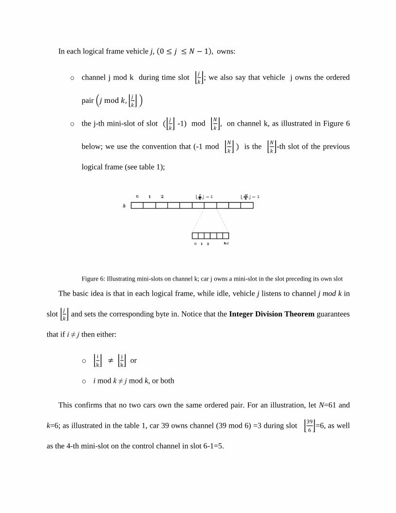
o the j-th mini-slot of slot ( 𝑗
𝑘 -1) mod
𝑁
𝑘 , on channel k, as illustrated in Figure 6
below; we use the convention that (-1 mod 𝑁
𝑘 ) is the
𝑁
𝑘 -th slot of the previous
logical frame (see table 1);
Figure 6: Illustrating mini-slots on channel k; car j owns a mini-slot in the slot preceding its own slot
The basic idea is that in each logical frame, while idle, vehicle j listens to channel j mod k in
slot 𝑗
𝑘 and sets the corresponding byte in. Notice that the Integer Division Theorem guarantees
that if i ≠ j then either:
o i
k ≠
j
k or
o i mod k ≠ j mod k, or both
This confirms that no two cars own the same ordered pair. For an illustration, let N=61 and
k=6; as illustrated in the table 1, car 39 owns channel (39 mod 6) =3 during slot 39
6 =6, as well
as the 4-th mini-slot on the control channel in slot 6-1=5.
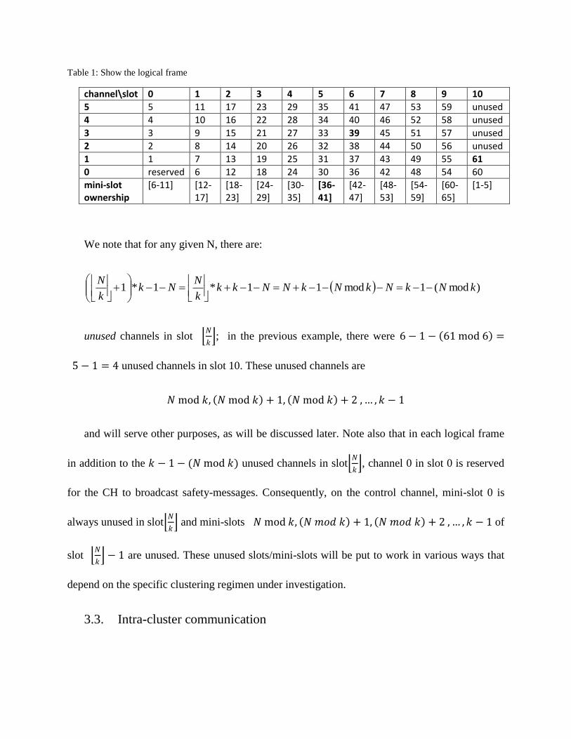
Table 1: Show the logical frame
channel\slot 0 1 2 3 4 5 6 7 8 9 10
5 5 11 17 23 29 35 41 47 53 59 unused
4 4 10 16 22 28 34 40 46 52 58 unused
3 3 9 15 21 27 33 39 45 51 57 unused
2 2 8 14 20 26 32 38 44 50 56 unused
1 1 7 13 19 25 31 37 43 49 55 61
0 reserved 6 12 18 24 30 36 42 48 54 60
mini-slot ownership
[6-11] [12-17]
[18-23]
[24-29]
[30-35]
[36-41]
[42-47]
[48-53]
[54-59]
[60-65]
[1-5]
We note that for any given N, there are:
)mod(1mod11*1*1 kNkNkNkNNkkk
NNk
k
N
unused channels in slot 𝑁
𝑘 ; in the previous example, there were 6 − 1 − 61 mod 6 =
5 − 1 = 4 unused channels in slot 10. These unused channels are
𝑁 mod 𝑘, 𝑁 mod 𝑘 + 1, 𝑁 mod 𝑘 + 2 , … , 𝑘 − 1
and will serve other purposes, as will be discussed later. Note also that in each logical frame
in addition to the 𝑘 − 1 − (𝑁 mod 𝑘) unused channels in slot 𝑁
𝑘 , channel 0 in slot 0 is reserved
for the CH to broadcast safety-messages. Consequently, on the control channel, mini-slot 0 is
always unused in slot 𝑁
𝑘 and mini-slots 𝑁 mod 𝑘, 𝑁 𝑚𝑜𝑑 𝑘 + 1, 𝑁 𝑚𝑜𝑑 𝑘 + 2 , … , 𝑘 − 1 of
slot 𝑁
𝑘 − 1 are unused. These unused slots/mini-slots will be put to work in various ways that
depend on the specific clustering regimen under investigation.
3.3. Intra-cluster communication
In the intra-cluster communication, we are looking at the single-hop cluster case first; multi-
hop cluster intra-cluster communication will be investigated later. Our goal is to design
lightweight communication protocols that avoid, to the largest extent possible, the involvement
of the CH in setting up connections between vehicles. As a single-hop cluster, all vehicles in the
cluster can communicate directly. Consequently, the cars do not need to discover their neighbors.
Each vehicle uses its own mini-slot to disseminate status information. The first byte of the
mini-slot can be used to encode 28 = 128 different situations; a few of them are listed below:
0 indicates that the vehicle is not communicating at the moment.
1 indicates that the vehicle is involved in communicating with some other vehicle in
the cluster; the binary encoding of the ID of the interlocutor follows in the second
byte.
2 indicates that the vehicle is involved in communicating with some other vehicle in
the cluster; the binary encodings of the IDs of the members of the multicast group
follows in the next 63 bytes.
125 confirmation of “Hello” message.
126 indicates that the vehicle will transmit a request during its upcoming slot (i.e.,
next slot).
127 indicates that the car will use its upcoming slot to transmit.
Different messages need to be transmitted inside the cluster. These messages are safety,
governance and non-safety messages. Also, the messages could be broadcasted or unicasted. We
will explain our scheme below.
Disseminating intra-cluster safety /governance messages: In this type of messages, the CH is
responsible for disseminating control messages. When a safety message needs to be broadcast to
the cluster the Ch interrupt the transmission/reception of non-safety data. Then, the CH will
change the status of its mini-slot to 127. Using the CH’s receiving slot, the CH will broadcast the
safety message to other vehicles in the cluster. This will be repeated on other available slots of
the next logical frame to achieve the effect of broadcasting to the entire cluster. Other vehicles,
in each logical frame, will be tuned in to one of these channels to pick up potential safety
messages. The CH may decide to disseminate safety messages to a subset of the vehicles in
which case it will also broadcast an N-bit vector, indicating which vehicles are targeted by the
message; if all bits are set, the message is a cluster-wide broadcast.
In addition to safety messages the previously-described mechanism is employed for cluster
governance messages including:
The updated value of N and multicast group setup requests.
Channels and slot times during which it has “office hours” and will listen to
individual requests.
Disseminating intra-cluster non-safety: For the non-safety messages, the CH uses its own
slot for non-safety data exchanges behaving as a usual vehicle.
Setting up an intra-cluster unicast communication: Unicast (a.k.a. point-to-point)
communications are set up without CH intervention. Suppose vehicle i wishes to talk with
vehicle j; setting up a connection between them is done as follows:
By tuning in to vehicle j’s own mini-slot, vehicle i determines whether or not car j is
available.
If so, vehicle i transmits a handshake packet on channel j mod k during time slot 𝑗
𝑘 .
Assuming no collision (i.e. some other vehicle may also want to talk to j), j will pick up the
handshake packet and will negotiate with vehicle i the parameters of the data exchange by
replying on channel i mod k during time slot 𝑖
𝑘 ; again, assuming no collision, the connection
between cars i and j has been set up. Now, both vehicles set up the first byte of their mini-slots to
indicate the status change. Once the connection has been set up, the two vehicles can
communicate either in i’s own slot or in j’s own slot or both, if possible. If vehicles i and j need
more than the basic amount of bandwidth, they need to seek permission from the CH to use one
or several extra unused time slots.
Setting up an intra-cluster multicast communication: Multicast (a.k.a. point-to-multipoint)
communications may be set up with or without CH intervention. Suppose vehicle j wishes to
establish a multicast group involving vehicles j, 𝑖1, 𝑖2, … , 𝑖𝑝 . If the multicast group is small,
vehicle j will attempt to send a handshake message to each of the remaining vehicles in the
multicast group. Once the group has been set up, vehicle j will transmit on channel j mod k
during time slot time 𝑗
𝑘 and all the other vehicles will listen to the channel. If the size of the
multicast group is large, vehicle j will send the CH a multicast group request consisting of its
own ID along with an N-bit vector with the bits corresponding to the multicast group set. Once
received by the CH, this multicast group setup request will be disseminated by the CH in the next
available logical frame, by all the modalities discussed above. Once the multicast group has been
set up, vehicle j will transmit to the group on channel j mod k during slot 𝑗
𝑘 .
3.4. Inter-cluster communication
The concept of clusters in VANET is used to avoid the interference between vehicles.
Vehicles in the same cluster should not suffer from this problem, as explained above. However,
interference could happen with other vehicles from different clusters, Figure 7. So, managing the
channels and the communications among the vehicles that are susceptible to interference must be
done for avoidance of collision and for passing messages to other clusters. This issue will be
studied and a solution will be developed in the future work.
Another type of inter-cluster communication is communicating with Road Side Units (RSU).
Communications in VANET are Vehicle-to-Vehicle (V2V) communication or Vehicle-to-
Infrastructure (V2I) communication. All we explained above is V2V, which does not cover RSU.
Communication with RSU is a V2I communication. Once the cluster gets in the range of a RSU,
vehicles in the cluster should able to communicate with RSU. That can be done by assigning a
slot to the RSU by giving it a local ID by the clusterhead. Once the local ID is assigned to the
RSU, vehicles can communicate with the RSU in the same fashion as intra-cluster
communication.
3.5. Cluster maintenance
Due to the movement of vehicles, the cluster will not stay the same for long time. Many
vehicles’ behavior may change the topology of the cluster. For example, a clusterhead leaving
the cluster, a new vehicle joining the cluster, a cluster member leaving the cluster, two clusters
get in range of each other, and a multi-hop cluster shrinks to a one-hop cluster. All these changes
in the cluster topology are going to be a dressed.
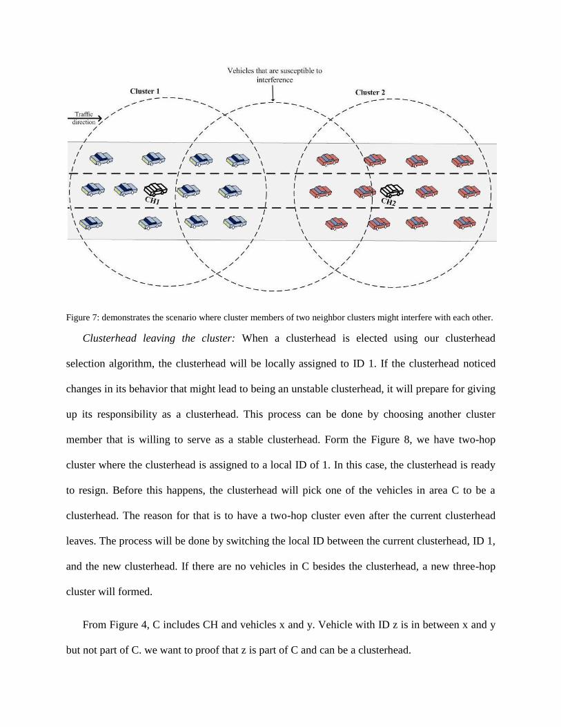
Figure 7: demonstrates the scenario where cluster members of two neighbor clusters might interfere with each other.
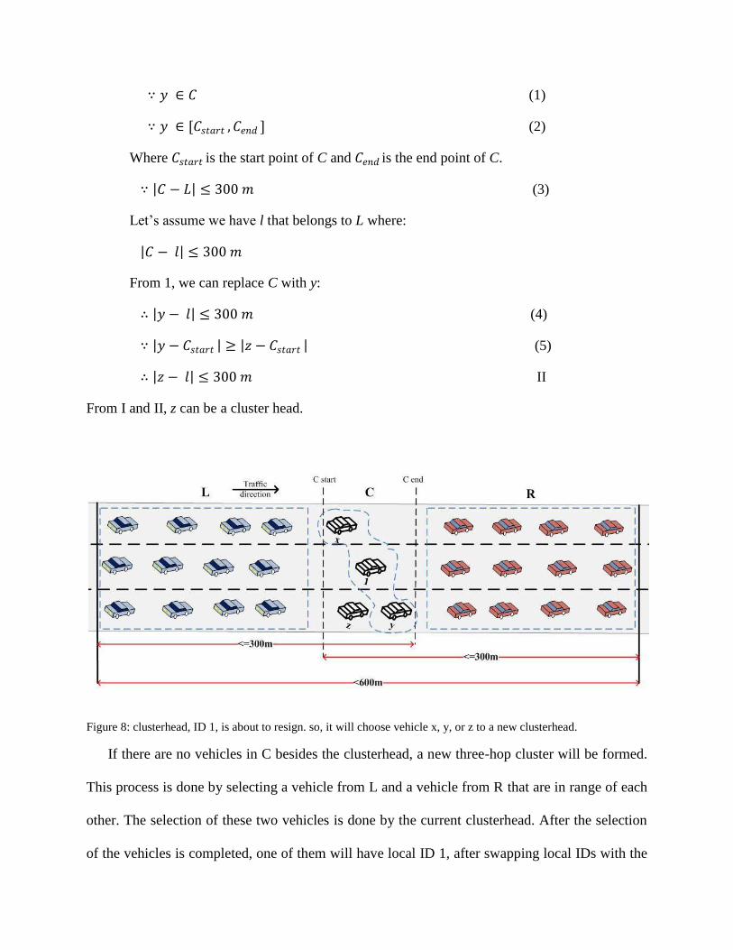
Clusterhead leaving the cluster: When a clusterhead is elected using our clusterhead
selection algorithm, the clusterhead will be locally assigned to ID 1. If the clusterhead noticed
changes in its behavior that might lead to being an unstable clusterhead, it will prepare for giving
up its responsibility as a clusterhead. This process can be done by choosing another cluster
member that is willing to serve as a stable clusterhead. Form the Figure 8, we have two-hop
cluster where the clusterhead is assigned to a local ID of 1. In this case, the clusterhead is ready
to resign. Before this happens, the clusterhead will pick one of the vehicles in area C to be a
clusterhead. The reason for that is to have a two-hop cluster even after the current clusterhead
leaves. The process will be done by switching the local ID between the current clusterhead, ID 1,
and the new clusterhead. If there are no vehicles in C besides the clusterhead, a new three-hop
cluster will formed.
From Figure 4, C includes CH and vehicles x and y. Vehicle with ID z is in between x and y
but not part of C. we want to proof that z is part of C and can be a clusterhead.
V – Set of vehicles in an area of 600m or less.
CH – is a vehicle that can communicate directly with all vehicles in V.
C – Set of vehicles that can do the job of CH.
C={x, y}, x- The farthest vehicle of C behind CH.
y- The farthest vehicle of C ahead of CH.
L – Set of vehicles that are behind CH and not part of C.
R – Set of vehicles that are ahead of the CH and not part of C.
Given:
∀ 𝑐 ∈ 𝐶 Adjust to all other vehicles in V
R.T.P:
Any vehicle z between x and y is part of C and can be a CH.
1. 𝑧 − 𝑙 ≤ 300 𝑚, where 𝑙 ∈ 𝐿
2. 𝑧 − 𝑟 ≤ 300 𝑚, where 𝑟 ∈ 𝑅
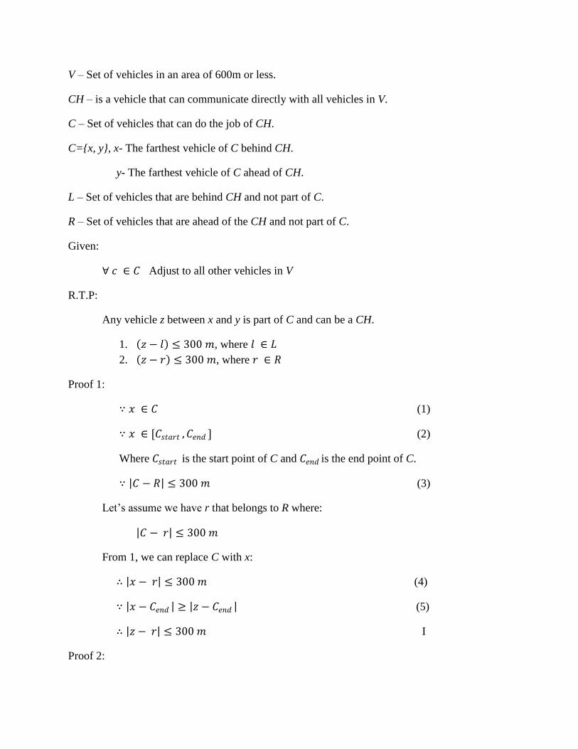
Proof 1:
∵ 𝑥 ∈ 𝐶 (1)
∵ 𝑥 ∈ [𝐶𝑠𝑡𝑎𝑟𝑡 , 𝐶𝑒𝑛𝑑 ] (2)
Where 𝐶𝑠𝑡𝑎𝑟𝑡 is the start point of C and 𝐶𝑒𝑛𝑑 is the end point of C.
∵ 𝐶 − 𝑅 ≤ 300 𝑚 (3)
Let’s assume we have r that belongs to R where:
𝐶 − 𝑟 ≤ 300 𝑚
From 1, we can replace C with x:
∴ 𝑥 − 𝑟 ≤ 300 𝑚 (4)
∵ 𝑥 − 𝐶𝑒𝑛𝑑 ≥ 𝑧 − 𝐶𝑒𝑛𝑑 (5)
∴ 𝑧 − 𝑟 ≤ 300 𝑚 I
Proof 2:
∵ 𝑦 ∈ 𝐶 (1)
∵ 𝑦 ∈ [𝐶𝑠𝑡𝑎𝑟𝑡 , 𝐶𝑒𝑛𝑑 ] (2)
Where 𝐶𝑠𝑡𝑎𝑟𝑡 is the start point of C and 𝐶𝑒𝑛𝑑 is the end point of C.
∵ 𝐶 − 𝐿 ≤ 300 𝑚 (3)
Let’s assume we have l that belongs to L where:
𝐶 − 𝑙 ≤ 300 𝑚
From 1, we can replace C with y:
∴ 𝑦 − 𝑙 ≤ 300 𝑚 (4)
∵ 𝑦 − 𝐶𝑠𝑡𝑎𝑟𝑡 ≥ 𝑧 − 𝐶𝑠𝑡𝑎𝑟𝑡 (5)
∴ 𝑧 − 𝑙 ≤ 300 𝑚 II
From I and II, z can be a cluster head.
Figure 8: clusterhead, ID 1, is about to resign. so, it will choose vehicle x, y, or z to a new clusterhead.
If there are no vehicles in C besides the clusterhead, a new three-hop cluster will be formed.
This process is done by selecting a vehicle from L and a vehicle from R that are in range of each
other. The selection of these two vehicles is done by the current clusterhead. After the selection
of the vehicles is completed, one of them will have local ID 1, after swapping local IDs with the
current clusterhead. If there are no vehicles in L and R that are in range, the clusterhead will
inform L and R that they will be two single-hop clusters. And the clusterhead selection algorithm
can be performed in both new clusters, L and R.
Once the cluster is created, it will not stay the same
In our scheme, the cluster is considered to be a single-hop. However, because of the dynamic
of vehicles in the road, two clusters may get in the range of each other. In this case, two clusters
will merge into one cluster; which may lead to three-hop cluster.
A new vehicle joining the cluster: We now describe the process of accepting a new car in the
cluster. Importantly, this operation is preempted by the broadcast of safety messages. When a
new car wishes to join the cluster, it will attempt to get the CH’s attention by transmitting in the
mini-slot of virtual car 0. Assuming that it was successful in getting the clusterhead’s attention,
the clusterhead will broadcast a “new Vehicle” message as discussed above and tentatively
assign the new-comer ID number 0. The new-comer will then transmit a “Hello” message in both
the clusterhead’s slot of the current frame as well as the virtual vehicle’s slot in the next frame;
this has the effect of broadcasting to the entire cluster. To confirm that the single-hop structure of
the cluster is preserved, each vehicle in the cluster will have to confirm receipt of the “Hello“. To
achieve this, each vehicle sets the first byte of its mini-slot to 125 and the clusterhead will read
all the mini-slots. If all the vehicles have confirmed receipt of the “Hello” message, the new
vehicles is accepted in the cluster and will be allocated the lowest available ID number. If
necessary, N has to be adjusted and the clusterhead will broadcast the updated information to the
cluster.
A cluster member leaving the cluster: When a vehicle is leaving the cluster, the clusterhead
places the local ID of the departing vehicle in the list of available IDs. Also, the clusterhead will
inform the other cluster members of the departure. These changes in the cluster may lead to
reassignment of the local IDs, which may lead to change the length of the transmission cycle.
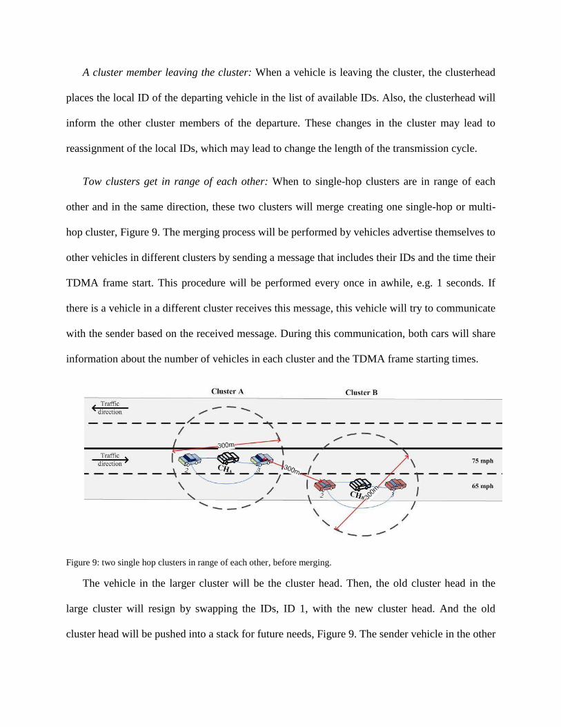
Tow clusters get in range of each other: When to single-hop clusters are in range of each
other and in the same direction, these two clusters will merge creating one single-hop or multi-
hop cluster, Figure 9. The merging process will be performed by vehicles advertise themselves to
other vehicles in different clusters by sending a message that includes their IDs and the time their
TDMA frame start. This procedure will be performed every once in awhile, e.g. 1 seconds. If
there is a vehicle in a different cluster receives this message, this vehicle will try to communicate
with the sender based on the received message. During this communication, both cars will share
information about the number of vehicles in each cluster and the TDMA frame starting times.
Figure 9: two single hop clusters in range of each other, before merging.
The vehicle in the larger cluster will be the cluster head. Then, the old cluster head in the
large cluster will resign by swapping the IDs, ID 1, with the new cluster head. And the old
cluster head will be pushed into a stack for future needs, Figure 9. The sender vehicle in the other
cluster will swap its ID with the cluster head of its cluster. And the old cluster head will be
pushed into a stack for future needs. The reason of pushing the old clusterheads in a stack is that
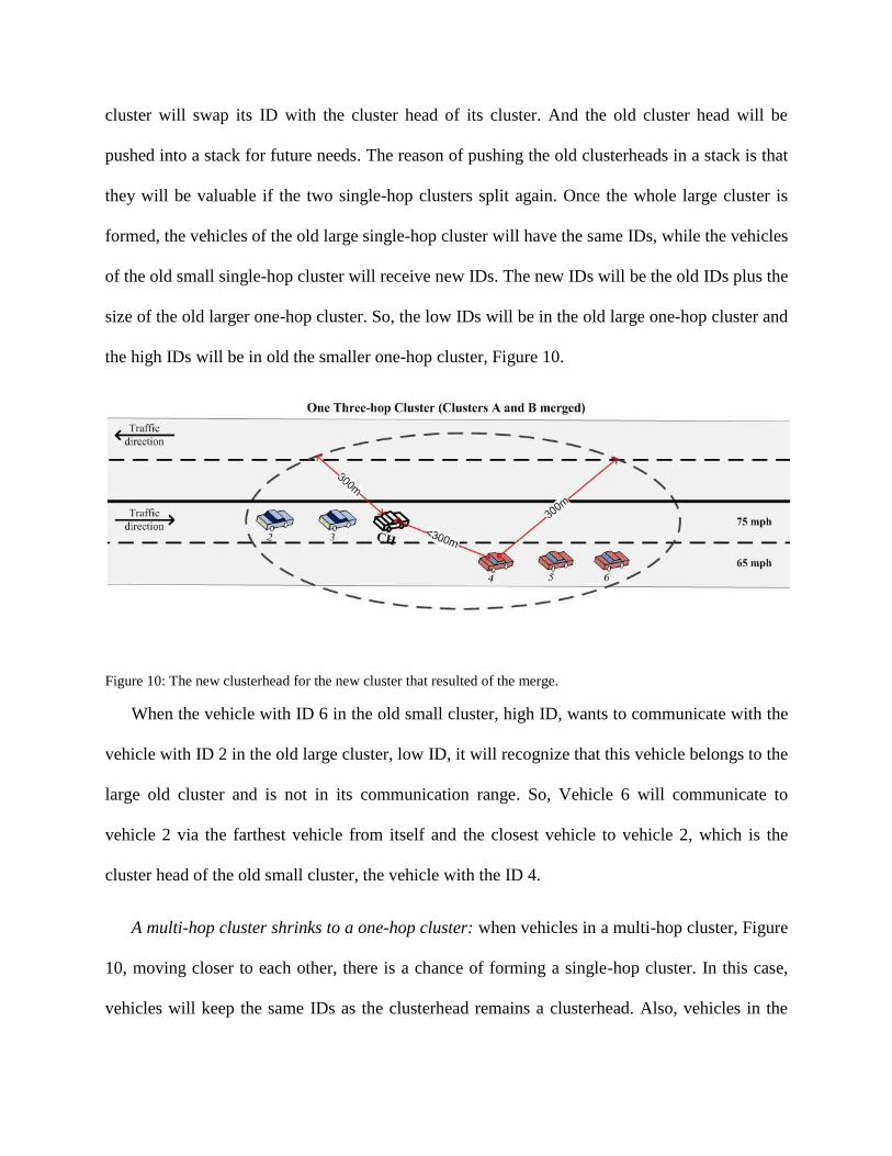
they will be valuable if the two single-hop clusters split again. Once the whole large cluster is
formed, the vehicles of the old large single-hop cluster will have the same IDs, while the vehicles
of the old small single-hop cluster will receive new IDs. The new IDs will be the old IDs plus the
size of the old larger one-hop cluster. So, the low IDs will be in the old large one-hop cluster and
the high IDs will be in old the smaller one-hop cluster, Figure 10.
Figure 10: The new clusterhead for the new cluster that resulted of the merge.
When the vehicle with ID 6 in the old small cluster, high ID, wants to communicate with the
vehicle with ID 2 in the old large cluster, low ID, it will recognize that this vehicle belongs to the
large old cluster and is not in its communication range. So, Vehicle 6 will communicate to
vehicle 2 via the farthest vehicle from itself and the closest vehicle to vehicle 2, which is the
cluster head of the old small cluster, the vehicle with the ID 4.
A multi-hop cluster shrinks to a one-hop cluster: when vehicles in a multi-hop cluster, Figure
10, moving closer to each other, there is a chance of forming a single-hop cluster. In this case,
vehicles will keep the same IDs as the clusterhead remains a clusterhead. Also, vehicles in the
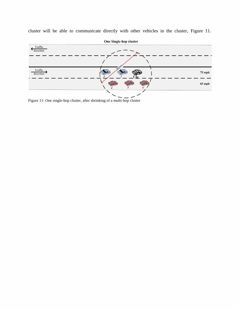
cluster will be able to communicate directly with other vehicles in the cluster, Figure 11.
Figure 11: One single-hop cluster, after shrinking of a multi-hop cluster
4. EVALUATION
We will design several simulations to test our techniques. We will use the ns-3 network
simulator [8], which is a follow-on to the popular ns-2 simulator. For VANETs, we will use
modules [1] that added well-known traffic mobility models, the Intelligent Driver Model (IDM)
[18] and the MOBIL lane change model [17].
We will be focusing on intra-cluster communications and the cluster formation. Inter-cluster
communication will covered as part of the cluster maintenance when two clusters are merging.
Here we list the evaluation plan:
1. Simulation environment:
We will test our algorithm in a highway environment with exits in the road.
Different levels of density (high, mid, low).
Different number of lanes.
2. Scenarios:
Formation of the cluster at the beginning of the simulation.
When new vehicles joining the cluster.
When cluster members leaving the cluster.
When the clusterhead is changing.
When the two clusters merging.
When a cluster is dividing.
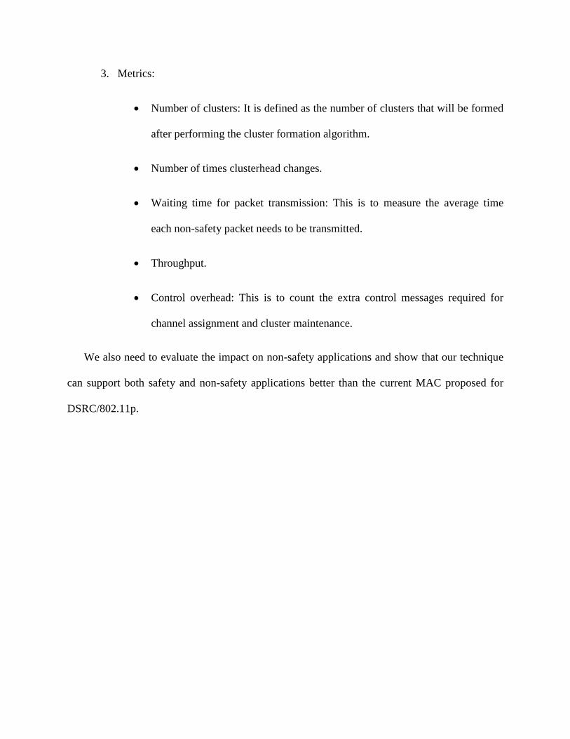
3. Metrics:
Number of clusters: It is defined as the number of clusters that will be formed
after performing the cluster formation algorithm.
Number of times clusterhead changes.
Waiting time for packet transmission: This is to measure the average time
each non-safety packet needs to be transmitted.
Throughput.
Control overhead: This is to count the extra control messages required for
channel assignment and cluster maintenance.
We also need to evaluate the impact on non-safety applications and show that our technique
can support both safety and non-safety applications better than the current MAC proposed for
DSRC/802.11p.
5. SUMMARY
In this work, we designed a TDMA slot reservation scheme for cluster-based VANET, in
which the collision-free intra-cluster communications were organized by the clusterheads using a
TDMA scheme. We started by introducing a new stable cluster formation scheme in VANET.
With the availability of lane detection, lane direction and map matching, we were able to select
the most stable clusterhead. Then, we proposed some solutions for network topology changes.
This scheme should make the changes in the network topology harmless to the cluster. We also
explain a light weight slot reservation algorithm. Our work is based on making vehicles
guarantee receiving non-safety messages without affecting the safety messages. We also changed
the concept of having two intervals by having vehicles listening to the control channel and the
service channels during the same time cycle. This scheme should be easy and fast to maintain.
6. PLAN
1. Design and evaluate a cluster formation algorithm in VANET:
We designed a lane-based clustering algorithm to provide stability in cluster lifetime for
vehicular ad-hoc networks. The results show that the clusterhead stays with the majority of
the cluster members.
Status: Completed and published.
Mohammad S. Almalag and Michele C. Weigle, "Using Traffic Flow for Cluster Formation
in Vehicular Ad-hoc Networks," In Proceedings of the Workshop On User MObility and
VEhicular Networks (ON-MOVE). Denver, CO, October 2010, pp. 631-636.
2. Design and evaluate a TDMA slot assignment algorithm:
We aim to test and evaluate our algorithm for TDMA slot assignment. We will use
simulation to test the message exchange between cluster members in a high way
environment. We are going to see how much non-safety messages are going to be
transmitted without any impact on the safety messages delivery.
a) Analytical. (Task 1)
b) Experimental. (Task 2)
3. Design and evaluate a cluster maintenance algorithm:
We aim to test and evaluate our cluster maintenance algorithm. We also are going to study
the dynamic of the cluster members and the effect of changes in network topology. Part of
our algorithm is studying how the clusterhead changing is handled.
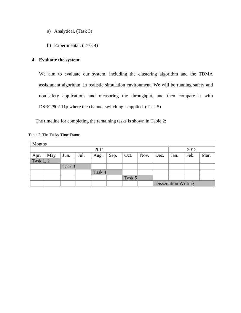
a) Analytical. (Task 3)
b) Experimental. (Task 4)
4. Evaluate the system:
We aim to evaluate our system, including the clustering algorithm and the TDMA
assignment algorithm, in realistic simulation environment. We will be running safety and
non-safety applications and measuring the throughput, and then compare it with
DSRC/802.11p where the channel switching is applied. (Task 5)
The timeline for completing the remaining tasks is shown in Table 2:
Table 2: The Tasks' Time Frame
Months
2011 2012
Apr. May Jun. Jul. Aug. Sep. Oct. Nov. Dec. Jan. Feb. Mar.
Task 1, 2
Task 3
Task 4
Task 5
Dissertation Writing
7. REFERENCES
[1] H. Arbabi and M. C. Weigle. Highway mobility and vehicular ad-hoc networks in ns-3. In
Proceedings of the Winter Simulation Conference, Baltimore, MD, Dec 2010.
[2] R. Aufrere, R. Chapuis, and F. Chausse. A model-driven approach for real-time road
recognition. Machine Vision and Applications, 13(2 2001):95–107, 2001.
[3] M. Bertozzi and A. Broggi. Gold: A parallel real-time stereo vision system for generic
obstacle and lane detection. IEEE Transactions on Image Processing, 7(1):62–81, January
1998.
[4] A. J. Dean and S. N. Brennan. Terrain-based road vehicle localization on multi-lane
highways. In Proceedings of the American Control Conference, pages 707–712, Piscataway,
NJ, USA, 2009. IEEE Press.
[5] P. Fan, J. G. Haran, J. Dillenburg, and P. C. Nelson. Traffic model for clustering
algorithm in vehicular ad-hoc network. In Proceedings of the Consumer Communications
and Networking Conference, volume 1, pages 168–172, 2006.
[6] P. Fan, J. G. Haran, J. F. Dillenburg, and P. C. Nelson. Cluster-based framework in
vehicular ad-hoc networks. In ADHOC-NOW, pages 32–42, 2005.
[7] M. Garg and R. K. Shyamasundar. A distributed clustering framework in mobile ad hoc
networks. In Proceedings of the International Conference on Wireless Networks, pages 32–
38, 2004.
[8] T. R. Henderson, S. Roy, S. Floyd, and G. F. Riley. ns-3 project goals. In Proceeding
from the 2006 workshop on ns-2: the IP network simulator, 2006.
[9] W. Holfelder. Vehicle safety communications in the US. In Proceedings of the 2007 ITS
World Congress, London, U.K., 2006.
[10] M. Jabbour, P. Bonnifait, and V. Cherfaoui. Enhanced local maps in a GIS for a precise
localisation in urban areas. In Proceedings of the 9th
IEEE Conference on Intelligent
Transportation Systems (ITSC 2006), 2006.
[11] M. Jiang, J. Li, and Y. Tay. Cluster based routing protocol. Internet Draft. draft-ietf-
manet-cbrp-spec-01, August 1999.
[12] S. Kuklinski and G. Wolny. Density based clustering algorithm for VANETs. Testbeds
and Research Infrastructures for the Development of Networks and Communities,
International Conference on, 0:1–6, 2009.
[13] C. D. McGillem and T. S. Rappaport. A beacon navigation method for autonomous
vehicles. IEEE Transactions on Vehicular Technology, 38(3):132–139, 1989.
[14] NAVTEQ. NAVTEQs NAVSTREETS Street Data Reference Manual, 3.4 edition,
October 2009.
[15] T. Oskiper, Z. Zhu, S. Samarasekera, and R. Kumar. Visual odometry system using
multiple stereo cameras and inertial measurement unit. In Proceedings Computer Vision and
Pattern Recognition, 2007.
[16] A. Ramalingam, S. Subramani, and K. Perumalsamy. Associativity based cluster
formation and cluster management in ad hoc networks. In Proceedings of the 9th
International
Conference On High Performance Computing, 2002.
[17] M. Treiber and D. Helbing. Realistische mikrosimulation von straenverkehr mit einem
einfachen modell. In Proceedings of the 16th
Symposium ”Simulationstechnik ASIM 2002”
Rostock, pages 514–520, September 2002.
[18] M. Treiber, A. Hennecke, and D. Helbing. Congested traffic states in empirical
observations and microscopic simulations. Phys Rev E Stat Phys Plasmas Fluids Relat
Interdiscip Topics, 62(2 Pt A):1805–24, 2000.
[19] US Department of Transportation. Standard Specification for Telecommunications and
Information Exchange Between Roadside and Vehicle Systems - 5 GHz Band Dedicated
Short Range Communications (DSRC) Medium Access Control (MAC) and Physical Layer
(PHY) Specifications. ASTM E2213-03, 2003.
[20] G. Wolny. Modified DMAC clustering algorithm for VANETs. In ICSNC ’08:
Proceedings of the 2008 Third International Conference on Systems and Networks
Communications, pages 268–273, Washington, DC, USA, 2008. IEEE Computer Society
[21] IEEE 1609.4 standard, - 2007
[22] Save Lives, Save Dollars. Prevent motor vehicle–related injuries
http://www.cdc.gov/injury/pdfs/cost-MV-a.pdf
[23] “The economic impact of motor vehicle crashes 2000,” National Highway Traffic Safety
Administration, May 2002.
[24] Mohammad Almalag, “Safety-Related Vehicular Applications,” In Vehicular Networks:
From Theory to Practice, Stephan Olariu and Michele C. Weigle, Eds. Chapman &
Hall/CRC, 2009.
[24] X. Hong, K. Xu, and M. Gerla, “Scalable routing protocols for mobile ad hoc net-
works,” Network, IEEE, vol. 16, no. 4, pp. 11–21, Jul/Aug 2002.
[25] Y. Gunter, B. Wiegel, and H. Grossmann, “Cluster-based medium access scheme for
vanets,” Intelligent Transportation Systems Conference, 2007. ITSC 2007. IEEE, pp. 343–
348, 30 2007-Oct. 3 2007.
[26] L. Bononi and M. Di Felice, “A cross layered mac and clustering scheme for efficient
broadcast in vanets,” Mobile Adhoc and Sensor Systems, 2007. MASS 2007. IEEE
Internatonal Conference on, pp. 1–8, Oct. 2007.
[27] Y. Gunter, B. Wiegel, and H. Grossmann, “Cluster-based medium access scheme for
vanets,” Intelligent Transportation Systems Conference, 2007. ITSC 2007. IEEE, pp. 343–
348, 30 2007-Oct. 3 2007.
[28] Z. Rawashdeh and S. Mahmud, “Media access technique for cluster-based vehicular ad
hoc networks,” Vehicular Technology Conference, 2008. VTC 2008-Fall. IEEE 68th, pp. 1–
5, Sept. 2008.
[29] F. Farnoud and S. Valaee, “Repetition-based broadcast in vehicular ad hoc networks in
rician channel with capture,” in INFOCOM 2009. The 28th Conference on Computer
Communications. IEEE, April 2008, pp. 1–6.
[30] B. Hassanabadi, L. Zhang, and S. Valaee, “Index coded repetition-based mac in
vehicular ad-hoc networks,” in Consumer Communications and Networking Conference,
2009. CCNC 2009. 6th IEEE, Jan. 2009, pp. 1–6.
[31] O. Kayis and T. Acarman, “Clustering formation for inter-vehicle communication,”
Intelligent Transportation Systems Conference, 2007. ITSC 2007. IEEE, pp. 636–641, 30
2007-Oct. 3 2007.
[32] H. Su and X. Zhang, “Clustering-based multichannel mac protocols for qos
provisionings over vehicular ad hoc networks,” Vehicular Technology, IEEE Transactions
on, vol. 56, no. 6, pp. 3309–3323, Nov. 2007.
[33] R. E. R.A. Santos and N. Seed, “Inter vehicular data exchange between fast moving road
traffic using ad-hoc cluster based location algorithm and 802.11b direct sequence spread
spectrum radio,” PostGraduate Networking Conference, 2003.
[34] Z.Y. Rawashdeh and S.M. Mahmud, "Toward Strongley Connected Clustering Structure
in Vehicular Ad hoc Networks", in Proceedings of VTC Fall, 2009
[35] D. Schrank, T. Lomax and S. Turner. “TTI’s 2010 URBAN MOBILITY REPORT”,
Texas Transportation Institute The Texas A&M University System. December 2010.
[36] G. Venkataraman, S. Emmanuel and S. Thambipillai. “Size-restricted cluster formation
and cluster maintenance technique for mobile ad hoc networks”, INTERNATIONAL
JOURNAL OF NETWORK MANAGEMENT, 2007; 17: 171–194
[37] L. Wang and S. Olariu. “Cluster Maintenance in Mobile Ad-hoc Networks”, Cluster
Computing, Vol. 8, Iss. 2-3, pp. 111, 2005
[38] J. A. Torkestani and M. R. Meybodi. “An efficient cluster-based CDMA/TDMA scheme
for wireless mobile ad-hoc network: A learning automata approach”, Journal of Network and
Computer Applications, 2010.
[39] Z. Wang and M. Hassan. “How Much of DSRC is Available for Non-Safety Use?”,
Proceedings of the fifth ACM international workshop on VehiculAr Inter-NETworking,
September 15, 2008, San Francisco, California, USA.
[40] P. Djukic and P. Mohapatra. “Soft-TDMAC: A Software TDMA-based MAC over
Commodity 802.11 hardware,” INFOCOM 2009, IEEE, pp. 1836-1844, April 2009


![Opt-TDMA/DCR: Optimized TDMA Deterministic Collision ......Firstly, we present probabilistic slot reservation approaches. DRAND [11] is a TDMA reservation method which is a distributed](https://img.pdfslide.us/doc/110x75/613ca51a4c23507cb6358460/opt-tdmadcr-optimized-tdma-deterministic-collision-firstly-we-present.jpg)