Embed Size (px)
Citation preview

FasdHTS Contract: G3RD – CT 2000 - 00100 TD 02.32.02.02
Fabrication of the V butt welds Specimens ( Task 3.2 )
June 2002
Author : Jose Alexandre
AF – I BV CAT CTH DH FSG GL GN TUHH IST LIS RS TNO
FasdHTS
2
G3RD – CT 2000 – 00100 FasdHTS TD 02.32.02.02
FATIGUE BASED DESIGN RULES FOR THE
APPLICATION OF HIGH TENSILE STEEL IN SHIPS
Doc. Ref.:
Date : 21 June 2002
TITLE :
Fabrication of Specimens ( Task 3.2 )
Author :
José Alexandre
Issued by :
LISNAVE Estaleiros Navais, S.A.
Summary: This report describes the design and fabrication of the Specimens for V- butt Welds, using Extra High Strength Steels, S690Q in conformity with EN 10137-2. The yield strength of this material is at least 690 N/mm². Dillinger Hütte GTS supplied all the material for these specimens.
Revision Date Description Pages Checked Approved 0 21-06-02 Draft EM CR 1 23-11-02 Final EM CR 2 14-02-03 Final 18 EM CR

3
CONTENTS
1. Object ...............................................................................................................4
2. Steel .................................................................................................................4
4. Preparation of specimens .................................................................................5
5. Welding.............................................................................................................6
6. Filler Metals: Chemical composition and mechanical properties.......................7
7. Welding sequence ............................................................................................7
8. Welding Parameters .........................................................................................8
9. Welding procedure specification.......................................................................8
10. Non-destructive testing welds...........................................................................9
11. Experiences......................................................................................................9 11.1. Preparation of the specimens ........................................................................................................9 11.2. Welding .......................................................................................................................................9 11.3. Economic aspects .........................................................................................................................9
12. Conclusion......................................................................................................10
13. References .....................................................................................................10
14. APPENDIX I....................................................................................................11
15. APPENDIX II...................................................................................................14
16. APPENDIX III..................................................................................................17

4
1. Object The fabrication of V-butt welds specimens for thinner plates are intended for testing with 4 mm plate specimens with L x W = 600 x 1200. 2. Steel The steel was supplied by Dillinger Hutten Worke, according with certificates in Appendix I.
3. Photo 1 – Steel plates when arrival
A summary of the mechanical properties of the steel is given in Table 1 and of the chemical composition in Table 2.
.
Steel Identification mark Quality Thickness Grade
Heat No.
Plate No.
1 2 3 4
DILL 690 DILL 690 DILL 690 DILL 690
4 mm 4 mm 4 mm 4 mm
690 T 690 T 690 T 690 T
78874 78874 78874 78874
91288 91289 91290 91291
Identification
mark Yield Stress
N/mm2 Tensile Strength
N/mm2 Elongation
(%) 1, 2, 3 and 4
732 808 15
Table 1 – Mechanical properties

5
Steel Chemical composition ( % ) Identification mark Qual. Thick C Mn Si P S Cr Ni Mo Al B
1,2,3 and 4 690 4mm 0,184 1.36 0.268 0.010 0.008 0.034 0.025 0.006 0.016 0.001
Table 2 – Chemical comp osition
4. Preparation of specimens The design proposed, as stated on document TD 01.51.01.01. Thinner plate thickness 4 mm. g=0 1 4 Fig.1 Welding preparation
Photo 2 – Welding preparation
The plates for the specimens were cut using steel cutting machine and grooves prepared by grinding, with an automatic machine. To avoid plate distortion during the welding, the plates were supported by temporary reinforcements according with the sketch below (fig.2)
50º 600
1200

6
ww Fig. 2 Reinforcements to avoid distortion plate After welding, the temporary reinforcements were removed, the surfaces were smooth by grinding and MPI was done to check for small cracks detection. No unacceptable indications were found. 5. Welding An automatic machine carried out welding, as we can observe in the photos 3 and.4, using MAG process with constant current and flux-cored wire to weld the specimens. A rutile wire with a diameter of 1.2 mm was used for all the specimens.
Photo 3 – Automatic machine Photo 4 – Welding The same welding process and wire was used for tack welding. The welding was done in the flat position (PA) for all specimens. To prevent start and stop defects, run-on and run-off plates was used for all specimens as shown in photos 5 and 6 Photos 5 and 6 – The use of run-on and run-off plates.
Welding direction

7
6. Filler Metals: Chemical composition and mechanical properties. The chemical composition is shown in table 3.
Chemical composition Designation C Mn Si S P Cr Ni Mo N
H.Fluxofill42
0.068 1.413 0.297 0.007 0.013 0.495 2.247 0.486 0.003
Table 3 – Chemical composition
The mechanical properties are shown in table 4.
Yield Strength N/mm2
Tensile Strength N/mm2
Elongation (%)
Impact Strength (J)
699
782 18 12
Table 4 – Mechanical properties
7. Welding sequence
1 – Step : Face welding. 1
2 – Step : Grinding back side.
3 – Step: Back welding. 2

8
Photos 6 and 7 – Welding process and welding aspect
8. Welding Parameters In table 5 is shown the welding parameters used for the specimens Model–A, without backing.
Filler Metal Current Weld Layers Process Class Dia.
(mm) Type
Polarity Amp. Range
Volt Range
Travel Speed (cm/min)
Heat Input
(Kj/mm)
1 2
Fcaw Fcaw
AWS A5.29 AWS A5.29
1.2 1.2
+ +
229 229
23.6 23.6
40.3 43.1
0.80 0.75
Table 5 – Without backing
In table 6 is shown the welding parameters used for the specimens Model –B, with ceramic backing.
Filler Metal Current Weld Layers Process Class Dia.
(mm) Type
Polarity Amp. Range
Volt Range
Travel Speed (cm/min)
Heat Input
(Kj/mm)
1 Fcaw AWS A5.29 1.2 + 229 23.6 31.57 1.03
Table 6 – With backing 9. Welding procedure specification As the Yard has no experience in HTS 690 fabrication, the welding procedure specification (WPS) were developed and prepared with information obtained from DILLINGER HUTTE GTS, Technical Information No. I / 1998, in which are given some fabrication guide lines, such as: Base metal characteristics: Filler metals and consumables for welding DILLIMAX Steels. Pre-heating temperature of 25ºC min. for thick. below 5 mm. Inter-pass temperature 220ºC max. No pre-heating was used to weld the 4 mm thickness plates. The specimens were welded according with the welding procedure specification No. V.002, in Appendix I.
9
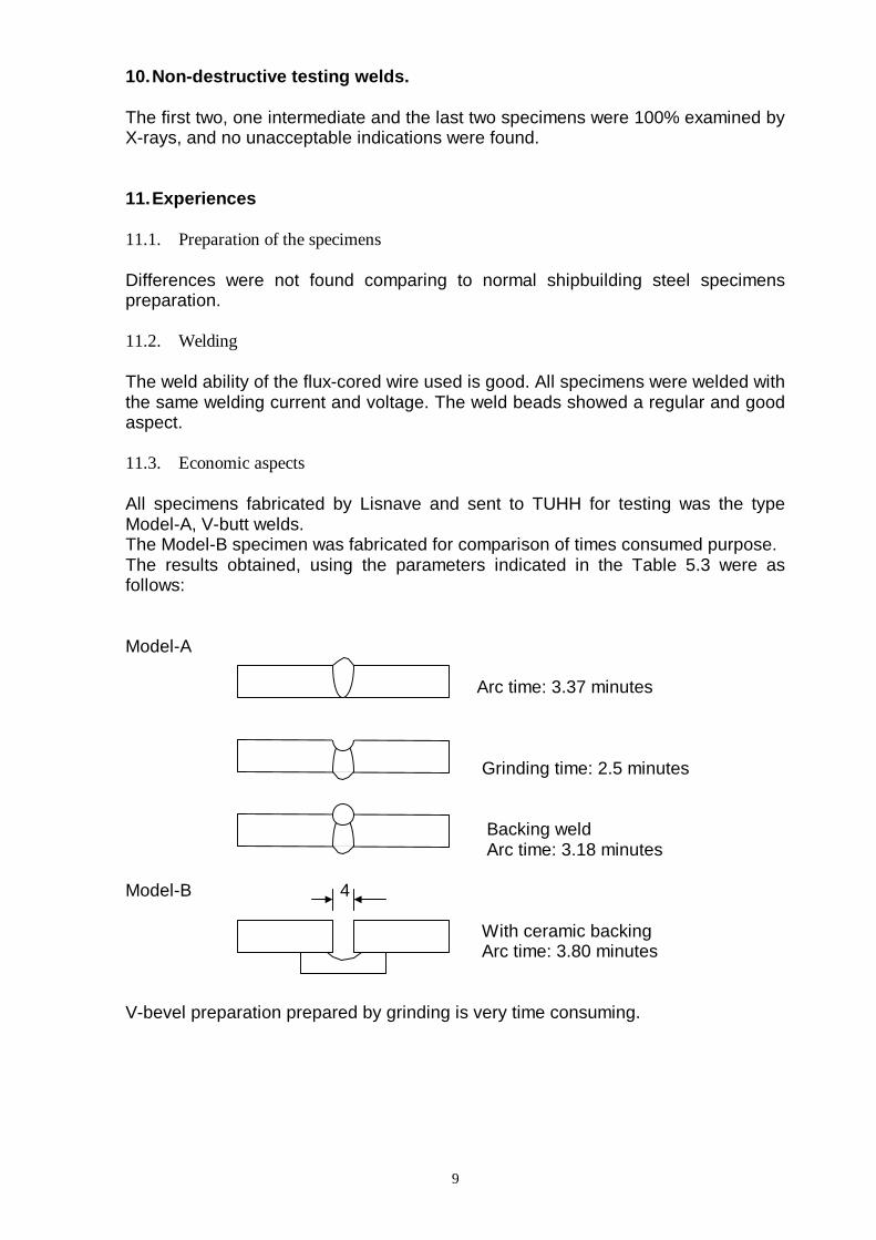
10. Non-destructive testing welds. The first two, one intermediate and the last two specimens were 100% examined by X-rays, and no unacceptable indications were found. 11. Experiences 11.1. Preparation of the specimens Differences were not found comparing to normal shipbuilding steel specimens preparation. 11.2. Welding The weld ability of the flux-cored wire used is good. All specimens were welded with the same welding current and voltage. The weld beads showed a regular and good aspect. 11.3. Economic aspects All specimens fabricated by Lisnave and sent to TUHH for testing was the type Model-A, V-butt welds. The Model-B specimen was fabricated for comparison of times consumed purpose. The results obtained, using the parameters indicated in the Table 5.3 were as follows: Model-A Arc time: 3.37 minutes Grinding time: 2.5 minutes Backing weld Arc time: 3.18 minutes Model-B 4 With ceramic backing Arc time: 3.80 minutes V-bevel preparation prepared by grinding is very time consuming.

10
12. Conclusion The welding of the specimens has been done without any production problems. From the point of view of expenses, the square butt welds are preferable; a considerable time is involved in the preparation of V-bevel. In a large scale production MAG welding process automatics with square butt welds and ceramic backing is to be considered. 13. References 1. TNO Programme for fatigue tests . Technical Document TD 00.51.01.01 FasdHTS 2. DILLIMAX – Technical Information N0.I/1998. 3. ASME IX – 1995 Boiler & Pressure Vessel Code

11
14. APPENDIX I
14.1. Welding Procedure Specification

12
WELDING PROCEDURE SPECIFICATION (QW-482) WPS No.: V-002
ACCORDING - ASME, Section IX SHEET No. 1 of 2
(See QW- 200.1) DATE : 15-05-01
SUPPORTING PQR No.
REVISION No.: 0 DATE: 15-05-2001 COMPANY NAME: LISNAVE BY: WELDING PROCEDURE(ES): FCAW TYPE(S): MECHANIZED AUTOMATIC, MANUAL, MACHINE, OR SEMI-AUTO
DETAILS JOINTS (QW-402) JOINT DESIGN: V-BUTT WELD GROOVE 50º 50º BACKING (YES): ------ (NO): NO BACKING MATERIAL (Type)
4
Metal Nonfusing Metal 1 Nonmetalic Other BASE METALS (QW-403) P-No. 1 to P-No. 1 OR SPEC. TYPE AND GRADE: HIGH TENSILE STEEL - HTS690 TO SPEC. TYPE AND GRADE: HIGH TENSILE STEEL - HTS690 OR CH. ANALYSIS AND MECH. PROP. TO CH. ANALYSIS AND MECH. PROP. THICKNESS RANGE: BASE METAL: PLATE GROOVE: 1.6 - 8 mm FILLET: ALL THICKNESS OF BASE METAL PIPE DIA. RANGE: NA GROOVE: NA FILLET: NA OTHER: NA FILLER METALS (QW-404) POSITIONS (QW-405) SPEC. No. (SFA): A5.29 - 80 POSITION(S) OF GROOVE: 1 G AWS No.(CLASS): E 111TG-K3* WELDING PROGRESSION: N/A F-No.: 6 POSITION(S) OF FILLET: N/A A-No.: 10 PREHEAT (QW-406) SIZE OF FILLER METALS: Ø 1.2 mm PREHEAT TEMP.: N/A WELD METAL INTERPASS TEMP. MAX.: N/A THICKNESS RANGE: PREHEAT MAINTENANCE: N/A GROOVE: 8 mm FILLET: UNLIMITED POSTWELD HEAT TREATMENT (QW-407) ELECTRODE-FLUX (CLASS): NA FLUX TRADE NAME: NA TEMPERATURE RANGE: N/A CONSUMABLE INSERT: NA TIME RANGE: N/A OTHER: * Fluxofil M42 / M21 (u) "Oerlikon"
ESTALEIROS NAVAIS, S.A.

13
WPS No: V-002
QW-482 (Back) SHEET No: 2 of 2
DATE: 15-05-01
REV.: 0
GAS (QW-408) ELECTRICAL CHARACTERISTICS (QW-409) PERCENT COMPOSITION CURRENT AC OR DC: DC POLARITY: + GAS(ES) MIXTURE FLOW RATE AMPS (RANGE): 230 VOLTS(RANGE): 30 SHIELDING: N/A Ar+20%CO2 15 l/min TUNGSTEN ELECTR. SIZE AND TYPE: N/A (PURE TUNGSTEN, 2% THORISTED,ETC)
TRAILING.: N/A N/A N/A MODE OF METAL TRANSFER FOR GMAW: SPRAY (SPRAY ARC, SHORT CIRCUTTING ARC, ETC,.)
BACKING..: N/A N/A N/A OTHERS: NA TECHNIQUE (QW-410) DETAILS IDENTIFICATION OF PASSES STRING OR WEAVE BEAD: STRINGER BEAD ORIFICE OR GAS CUP SIZE: N/A Initial and Interpass Cleaning (Brushing, :Grinding, etc.) GRINDING METHOD OF BACK GOUGING: GRINDING 2 OSCILATION: N/A CONTACT TUBE TO WORK DISTANCE: N/A 1 MULTIPLE OR SINGLE PASS (PER SIDE): SINGLE PASS MULTIPLE OR SINGLE ELECTRODES: SINGLE TRAVEL SPEED (RANGE): 40cm/min PEENING: N/A OTHER: N/A OTHER FILLER METAL CURRENT TRAVEL (EG., REMARKS, COMENTS, HOT WIRE, WELD TYPE AMPS VOLT SPEED ADDITION, TECHNIQUE, TORCH ANGLE, ETC,.) LAYERS PROCESS CLASS DIAM. POLAR. RANGE RANGE RANGE 1 & 2 FCAW E 111TG-K3 1.2 DC + 230 30 40 ALL VALUES +/- 10%
ORGANISATION: LISNAVE Jose Alexandre DATE: 2001/02/22 SIGN / STAMP
APPROVED BY: DATE: SIGN / STAMP

14
15. APPENDIX II
15.1. Steel Plate Certificates

15

16

17
16. APPENDIX III
16.1. Welding Consumable Data

18