Embed Size (px)
Citation preview

TC 9-237
CHAPTER 12
SPECIAL APPLICATIONS
Section I. UNDERWATER CUTTING AND WELDING WITH THE ELECTRIC ARC
12-1. GENERAL WARNING
Safety precautions must be exercised in underwater cutting and weld-ing. The electrode holder and cable must be insulated, the currentmust be shut off when changing elecrodes, and the diver should aoidcontact between the electrode and grounded work to prevent electrical shock.
a. Underwater Arc Cutting. In many respects, underwater arc cutting is quitesimilar to underwater gas cutting. An outside jet of oxygen and compressed air isneeded to keep the water from the vicinity of the metal being cut. Arc torches forunderwater cutting are produced in a variety of types and forms.structed to connect to oxygen-air pressure sources. Electrodes used may be carbonor metal. They are usually hollow in order to introduce a jet of oxygen into themolten crater created by the arc. The current practice is to use direct currentfor all underwater cutting and welding. In all cases, the electrode is connectedto the negative side of the welding generator.
They a re con-
b. Underwater Arc Welding. Underwater arc welding may be accomplished in muchthe same manner as ordinary arc welding. The only variations of underwater arcwelding from ordinary arc welding are that the electrode holder and cable must bewell insulated to reduce current leakage and electrolysis, and the coated elec-trodes must be waterproofed so that the coating will not disintegrate underwater.The waterproofing for the electrode is qenerally a cellulose nitrate in which cellu-loid has been dissolved. Ordinary airplane dope with 2.0 lb (O.9 kg) ofadded per gallon is satisfactory.
12-2. UNDERWATER CUTTING TECHNIQUE
a. Torch. The torch used in underwater cutting is a fully insulated
celluloid
underwatercutting torch that utilizes the electric arc-oxygen cutting process using a tubularsteel-covered, insulated, and waterproofed electrode. It utilizes the twist typecollet for gripping the electrode and includes an oxygen valve lever and connec-tions for attaching the welding lead and an oxygen hose. It is equipped to handleup to a 5/16-in. (7.9-mm) tubular electrode. In this process, the arc is strucknormally and oxygen is fed through the electrode center hole to provide cutting.The same electrical connections mentioned above are employed.
b. The welding techniques involve signaling the surface helper to close theknife switch when the welder begins. The bead technique is employed using the dragtravel system. When the electrode is consumed, the welder signals “current off” tothe helper who opens the knife switch. “Current on” is signaled when a new elec-trode is positioned against the work. The current must be connected only when theelectrode is against the work.
12-1
TC 9-237
12-2. UNDERWATER CUTTING TECHNIQUE (cont)
c. Steel electrodes used for underwater cutting should be 14 in. (356 mm) longwith a 5/16-in. (7.9-mm) outside diameter and an approximate 0.112-in. (2.845-mm)inside diameter hole. The electrode should have an extruded flux coating and bethoroughly waterproofed for underwater work.gives the best result with steel electrcdes. When using graphite or carbon elec-trodes, 600 to 700 amps are required with a voltage setting around 70.
A welding current of 275 to 400 amps
trode in contact with the work. Depress the oxygen lever slightly and call for d. When working underwater, the cut is started by placing the tip of the elec-
current. When the arc is established, the predetermined oxygen pressure (e below)is released and the metal is pierced.contact with the work, cutting at the greatest speed at which complete penetration
When the electrode is consumed, the current is turned off. A new electrode is theninserted and the same procedure is repeated until the cut is finished.
The electrode is then kept in continuous
can be maintained. The electrode should be held at a 90 degree angle to the work.
e.given plate thickness is the normal cutting pressure required in ordinary air cut-ting plus the depth in feet multiplied by 0.445. As an example, 2-1/4-in.(57.15-mn) plate in normal air cutting requires 20 psi (138 kPa). Therefore, at 10ft (3 m) underwater, the following result would be reached:
Normal predetermined oxygen pressure required for underwater cutting for a
20 + (10 x 0.445) = 24 psi (165 kPa).
NOTEAllowance for pressure drop in the gas line is 10 to 20 psi (69 to 138kPa) per 100 ft (30 m) of hose.
12-3. UNDERWATER WELDING TECHNIQUE
a. General. Underwater welding has been restricted to salvage operations andemergency repair work. It is limited to depths helm the surface of not over 30 ft(9 m). Because of the offshore exploration, drilling, and recovery of gas and oil,it is necessary to lay and repair underwater pipelines and the portion of drillrigs and production platforms which are underwater. There are two major categoriesof underwater welding; welding in a wet environment and welding in a dry environ-ment.
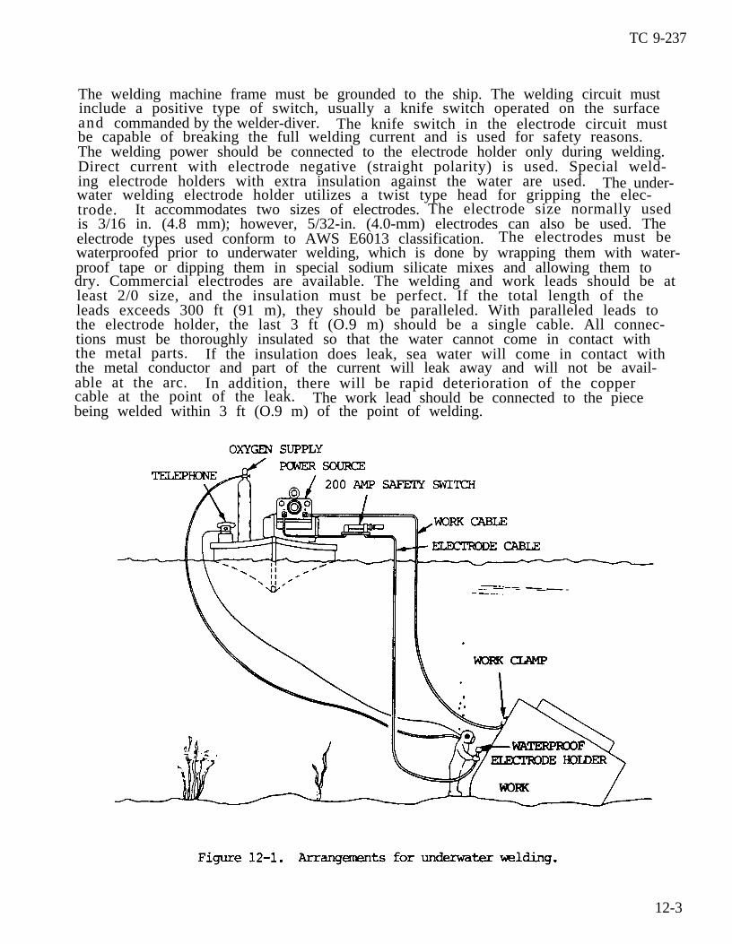
(1) Welding in the wet (wet environment) is used primarily for emergencyrepairs or salvage operations in shallow water. The pcor quality of welds made inthe wet is due to heat transfer, welder visibility, and hydrogen presence in thearc atmosphere during welding. When completely surrounded by water at the arcarea, the high temperature reducing weld metal quality is suppressed, and there isno base metal heat buildup at the weld. The arc area is composed of water vapor.The arc atmosphere of hydrogen and the oxygen of the water vapor is absorbed in themolten weld metal. It contributes to porosity and hydrogen cracking. In addition,welders working under water are restricted in manipulating the arc the same as onthe surface. They are also restricted by low visibility because of their equipmentand the water contaminants, plus those generated in the arc. Under the most idealconditions, welds produced in the wet with covered electrodes are marginal. Theymay be used for short periods as needed but should be replaced with quality weldsas soon as possible. Underwater in-the-wet welding is shown in figure 12-1. Thepower source should be a direct current machine rated at 300 or 400 amperes. Motorgenerator welding machines are most often used for underwater welding in-the-wet.
12-2
TC 9-237
The welding machine frame must be grounded to the ship. The welding circuit mustinclude a positive type of switch, usually a knife switch operated on the surfaceand commanded by the welder-diver. The knife switch in the electrode circuit mustbe capable of breaking the full welding current and is used for safety reasons.The welding power should be connected to the electrode holder only during welding.Direct current with electrode negative (straight polarity) is used. Special weld-ing electrode holders with extra insulation against the water are used. The under-water welding electrode holder utilizes a twist type head for gripping the elec-trode. It accommodates two sizes of electrodes.is 3/16 in. (4.8 mm); however, 5/32-in. (4.0-mm) electrodes can also be used. Theelectrode types used conform to AWS E6013 classification.waterproofed prior to underwater welding, which is done by wrapping them with water-proof tape or dipping them in special sodium silicate mixes and allowing them to
least 2/0 size, and the insulation must be perfect. If the total length of theleads exceeds 300 ft (91 m), they should be paralleled. With paralleled leads tothe electrode holder, the last 3 ft (O.9 m) should be a single cable. All connec-tions must be thoroughly insulated so that the water cannot come in contact withthe metal parts. If the insulation does leak, sea water will come in contact withthe metal conductor and part of the current will leak away and will not be avail-able at the arc. In addition, there will be rapid deterioration of the coppercable at the point of the leak. The work lead should be connected to the piecebeing welded within 3 ft (O.9 m) of the point of welding.
The electrode size normally used
The electrodes must be
dry. Commercial electrodes are available. The welding and work leads should be at
12-3
TC 9-237
12-3. UNDERWATER CUTTING TECHNIQUE (cont)
(2) Welding in-the-dry (dry environment) produces high-quality weld jointsthat meet X-ray and code requirements. The gas tungsten arc welding process produc-es pipe weld joints that meet quality requirements. It is used at depths of up to200 ft (61 m) for joining pipe. The resulting welds meet X-ray and weld require-ments. Gas metal arc welding is the best process for underwater welding in-the-dry. It is an all-position process and can be adopted for welding the metals in-volved in underwater work. It has been applied successfully in depths as great as180 ft (55 m). There are two basic types of in-the-dry underwater welding. Oneinvolves a large welding chamber or habitat known as hyperbaric welding. It pro-vides the welder-diver with all necessary welding equipment in a dry environment.The habitat is sealed around the welded part. The majority of this work is onpipe, and the habitat is sealed towater and is covered by a grating.equal to the water pressure at the
b. Direct current must be usedgenerally have ample capacity. To
the pipe. The chamber bottom is exposed to openThe atmosphere pressure inside the chamber is
operating depth.
for underwater welding and a 400 amp welder willproduce satisfactory welds underwater, the volt-
age must run about 10 volts and the current about 15 amps above the values used forordinary welding.
c. The procedure recommended for underwater welding is simply a touch tech-nique. The electrode is held in light contact with the work so that the crucibleformed by the coating at the end of the electrode acts as an arc spacer. To pro-duce 1/2 in. (12.7 mm) of weld bead per 1.0 in. (25.4 mm) of electrode consumed intee or lap joint welding, the electrode is held at approximately 45 degrees in thedirection of travel and at an angle of about 45 degrees to the surface being weld-ed. To increase or decrease weld size, the lead angle may be decreased or in-creased. The same procedure applies to welding in any position. No weaving orshipping is employed at any time. In vertical welding, working from the top downis recommended.
d. The touch technique has the following advantages:
(1) It
(2) It
(3) It
(4) It
makes travel speed easy to control.
produces uniform weld surfaces almost automatically.
provides good arc stability.
permits the diver to feel his way where visibility is bad or workingposition is awkward.
(5) It reduces slag
(6) It assures good
e. In general, largerployed in normal welding.
inclusions to
penetration.
a minimum.
electrodes are used in underwater welding than are em-For example, when welding down on a vertical lap weld on
1/8 to 3/16 in. (3.2 to 4.8 mm) material, a 1/8- or-5/32-in. (3.2- or 4.0-mm) elec-trode would usually be used in the open air. However, a 3/16- or 7/32-in. (4.8- or5.6-mm) electrode is recommended for underwater work because the cooling action ofthe water freezes the deposit moreble for the same reason. Usually,
quickly. Higher deposition rates are also possi-tee and lap joints are used in salvage opera-
12-4

TC 9-237
tions because they are easier to prepare and they provide a natural groove to guidethe electrode. These features are important under the difficult working conditionsencountered underwater. Slag is light and has many nonadhering qualities. Thismeans the water turbulence is generally sufficient to remove it. The use of clean-ing tools is not necessary. However, where highest quality multipass welds arerequired, each pass should be thoroughly cleaned before the next is deposited.
f. Amperages given in table 12-1 are for depths up to 50 ft (15.2 m). As depthincreases, amperage must be raised 13 to 15 percent for each additional 50 ft (15.2m) . For example, the 3/16-in. (4.8-mm) electrode at 200 ft (61 m) will requireapproximately 325 amperes to assure proper arc stability.
Section II. UNDERWATER CUTTING WITH OXYFUEL
12-4. GENERAL
Underwater cutting is accomplished by use of the oxyhydrogen torch with a cylindri-cal tube around the torch tip through which a jet of compressed air is blown. Theprinciples of cutting under water are the same as cutting elsewhere, except thathydrogen is used in preference to acetylene because of the greater pressure re-quired in making cuts at great depths. Oxyacetylene may be used up to 25-ft(7.6-m) depths; however, depths greater than 25.0 ft (7.6 m) require the use ofhydrogen gas.
12-5. CUTTING TECHNIQUE
a. Fundamentally, underwater cutting is virtually the same as any hand cuttingemployed on land. However, the torch used is somewhat different. It requires atube around the torch tip so air and gas pressure can be used to create a gas pock-e t . This will induce an extremely high rate of heat at the work area since waterdispels heat much faster than air. The preheating flame must be shielded fromcontact with the water. Therefore, higher pressures are used as the water leveldeepens (approximately 1.0 lb (0.45 kg) for each 2.0 ft (0.6 m) of depth). Initialpressure adjusments are as follows:
12-5

TC 9-237
12-5. CUTTING TECHNIQUE (cont)
b. While the cutting operation itself is similar as on land, a few differencesare evident. Same divers light and adjust the f1ame before descending. There is,however, an electric sparking device which is used for underwater ignition. Thisdevice causes somewhat of an explosion, but it is not dangerous to the operator.
c. When starting to preheat the metal to be cut, the torch should be held so
start the cut, the bell should be firmly pressed on the metal since the compressedair will travel with the high pressure oxygen and escape through the kerf.these circumstances, the preheated gases will prevent undue “chilling” by the sur-rounding water. No welder on land would place a hand on the torch tip when cut-ting. However, this is precisely what the diver does underwater since the tip,bell, or torch will become no more than slightly warm under water. The diver, byplacing the left hand around the torch head, can hold the torch steady and manipu-late it more easily.
the upper rim of the bell touches the metal. When the metal is sufficiently hot to
Under
d. Due to the rapid dissipation of heat, it is essential that the cut be start-ed by cutting a hole a distance from the outer edge of the plate. After the holehas been cut, a horizontal or vertical cut can be swiftly continued. A diver whohas not previously been engaged in underwater cutting must make test cuts beforesuccessfully using an underwater cutting torch.
Section III. METALLIZING
12-6. GENERAL
a. General.
(1) Metallizing is used to spray metal coatings on fabricated workplaces.The coating metal initially is in wire or powder form. It is fed through a specialgun and melted by an oxyfuel gas flame, then atomized by a blast of compressed
The air and combustion gases transport the atomized molten metal onto a pre-pared surface, where the coating is formed (fig. 12-2).a i r .
12-6
TC 9-237
(2) The metallizing process uses a welding spray gun to enable the welder toplace precisely as much or as little weld metal as necessary over any desired sur-face. Metal deposits as thin as 0.003 in. (0.076 mm) to any desired thickness maybe made. The process is versatile, time-saving, and, in some cases, more economi-cal than other welding or repair procedures.
(3) Metallized coatings are used to repair worn parts, salvage mismachinedcomponents, or to provide special properties to the surface of original equipment.Metallized coatings are used for improving bearing strength, adding corrosion orheat resistance, hard-facing, increasing lubricity, improving thermal and electri-cal conductivity, and producing decorative coatings.
(4) Corrosion resistant coatings such as aluminum and zinc are applied toship hulls, bridges, storage tanks, and canal gates, for example. Hard-facing isapplied to shafting, gear teeth, and other machine components, as well as to miningequipment, ore chutes, hoppers, tracks, and rails. Coatings with combined bearingand lubricity properties are used to improveslides, and ways.
b. Characteristics of Coated Surfaces.
the surface life of machine shafting,
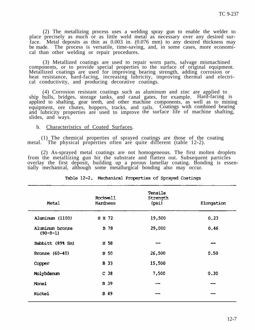
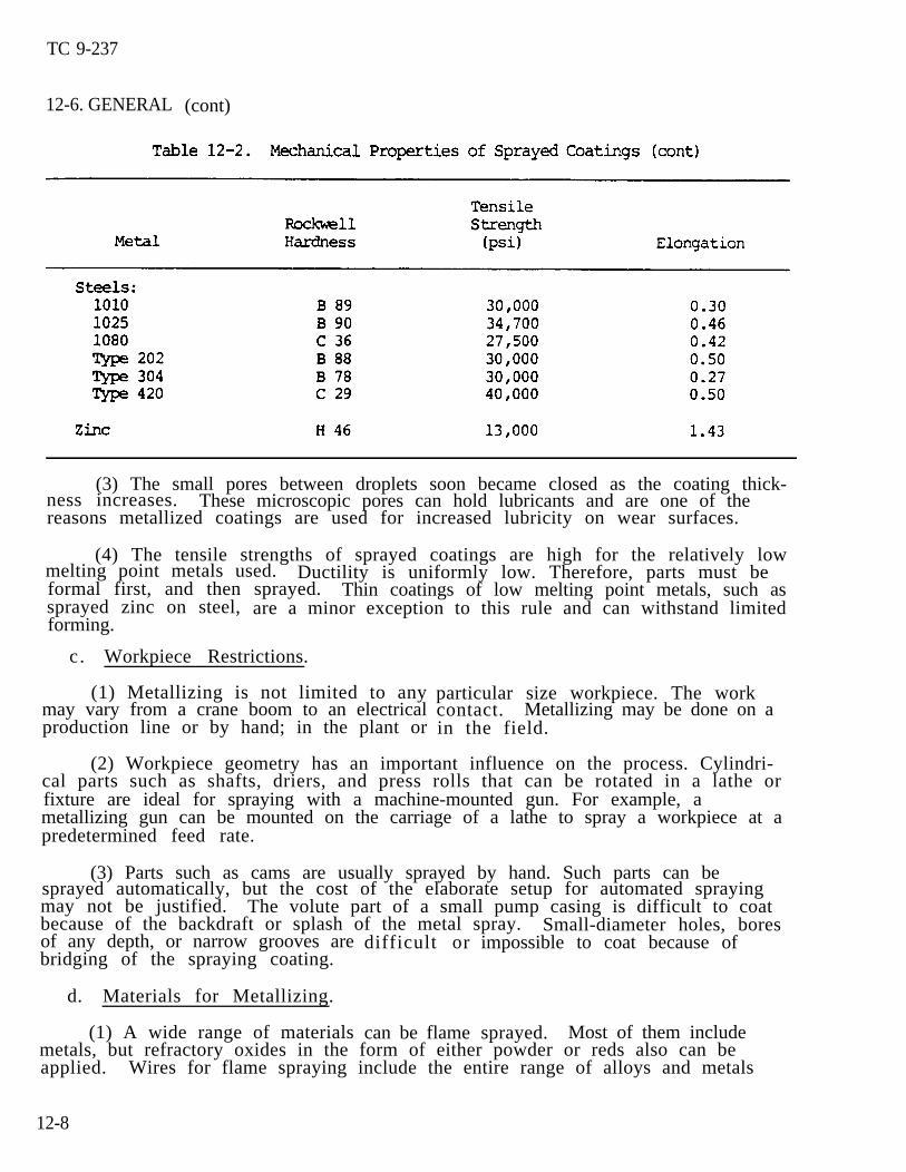
(1) The chemical properties of sprayed coatings are those of the coatingmetal. The physical properties often are quite different (table 12-2).
(2) As-sprayed metal coatings are not homogeneous. The first molten dropletsfrom the metallizing gun hit the substrate and flatten out. Subsequent particlesoverlay the first deposit, building up a porous lamellar coating. Bonding is essen-tially mechanical, although some metallurgical bonding also may occur.
12-7
TC 9-237
12-6. GENERAL (cont)
(3) The small pores between droplets soon became closed as the coating thick-ness increases. These microscopic pores can hold lubricants and are one of thereasons metallized coatings are used for increased lubricity on wear surfaces.
(4) The tensile strengths of sprayed coatings are high for the relatively lowmelting point metals used. Ductility is uniformly low. Therefore, parts must beformal first, and then sprayed. Thin coatings of low melting point metals, such assprayed zinc on steel, are a minor exception to this rule and can withstand limitedforming.
c. Workpiece Restrictions.
(1) Metallizing is not limited to anymay vary from a crane boom to an electricalproduction line or by hand; in the plant or
particular size workpiece. The workcontact. Metallizing may be done on ain the field.
(2) Workpiece geometry has an important influence on the process. Cylindri-cal parts such as shafts, driers, and press rolls that can be rotated in a lathe orfixture are ideal for spraying with a machine-mounted gun. For example, ametallizing gun can be mounted on the carriage of a lathe to spray a workpiece at apredetermined feed rate.
(3) Parts such as cams are usually sprayed by hand. Such parts can besprayed automatically, but the cost of the elaborate setup for automated sprayingmay not be justified. The volute part of a small pump casing is difficult to coatbecause of the backdraft or splash of the metal spray. Small-diameter holes, boresof any depth, or narrow grooves arebridging of the spraying coating.
d. Materials for Metallizing.
(1) A wide range of materials
difficult or
can be flame
impossible to coat because of
sprayed. Most of them includemetals, but refractory oxides in the form of either powder or reds also can beapplied. Wires for flame spraying include the entire range of alloys and metals
12-8
from lead, which melts at 618 OF (326 OC), to molybdenum with a melting4730 OF (2610 OC). Higher melting point materials also can be sprayed,plasma-arc spray gun is required.
TC 9-237
point ofbut a
(2) Between the extremes of lead and molybdenum are common metal coatingssuch as zinc, aluminum, tin, copper, various brasses, bronzes and carbon steels,stainless steels, and nickel-chromium alloys.one workpiece. For example, molybdenum or nickel aluminide often is used as a thincoating on steel parts to increase bond strength.applied to build up the deposit.
Spray coatings may be combined on
Then another coating metal is
e. Surface Preparation.
(1) Surfaces for metallizing must be clean. They also require roughening toensure a good mechanical bond between the workpiece and coating. Grease, oil, andother contaminants are rearmed with any suitable solvent. Cast iron or other po-rous metals should be preheated at 500 to 800 OF (260 to 427 OC) to remove en-
prior to preheating.
trapped oil or other foreign matter. Sand blasting may be used to remove excessivecarbon resulting from preheating cast iron. Chemical cleaning may be necessary
(2) Undercutting often is necessary on shafts and similar surfaces to permita uniformly thick buildup on the finished part. The depth of undercutting dependson the diameter of the shaft and on service requirements. If the undercut surfacebecomes oxidized or contaminated, it should be cleaned before roughening and spray-ing.
(3) Roughening of the workpiece surface usually is the final step beforespraying. Various methods are used, ranging from rough threading or threading andknurling to abrasive blasting and electric bonding.
the roughened surface to improve the bond strength of subsequent coatings. Applica-tions that require only a thin coating of sprayed metal often eliminate the roughen-
other metal.
(4) Thin molybdenum or nickel aluminide spray coatings are often applied to
ing step and go directly to a bonding coat. The surface is then built up with some
f . Coating Thickness.
(1) Cost and service requirements are the basis for determiningmaximum coating thickness for a particular application, such as building up a wornmachine part. Total metallizing cost includes cost of preparation, oxygen, fuelgas and materials , application time , and finishing operations. If repair costs aretoo high, it may be more economical to buy a replacement part.
the practical
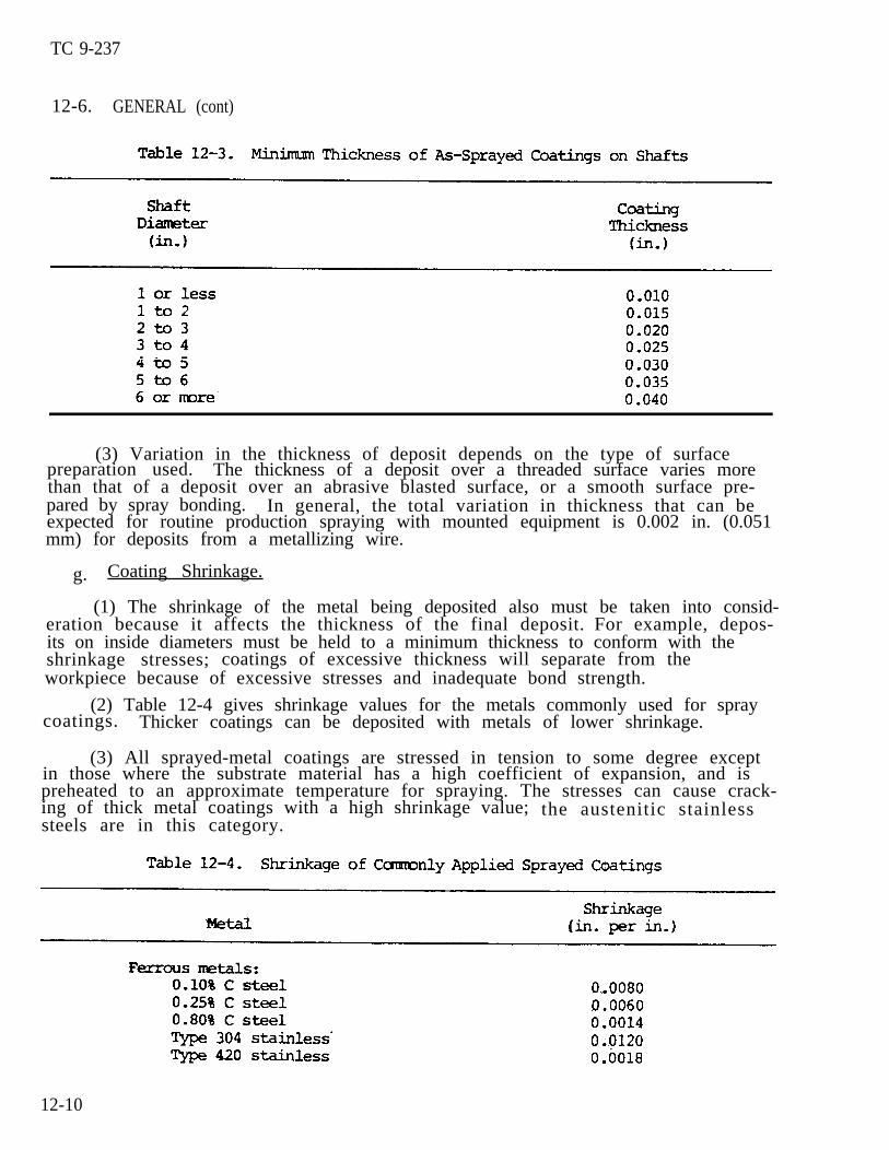
(2) The total thickness for the as-sprayed coating on shafts is determinedthe maximum wear allowance, the minimum coating thickness that must be sprayed, andthe amount of stock required for the finishing operation. The minimumthickness that must be sprayed depends on the diameter of the shaft and is given intable 12-3, p 12-10. For press-fit sections, regardless of diameter, a minimum of0.005 in. (0.127 mm) of coating is required.
by
c o a t i n g
12-9
TC 9-237
12-6. GENERAL (cont)
(3) Variation in the thickness of deposit depends on the type of surfacepreparation used. The thickness of a deposit over a threaded surface varies morethan that of a deposit over an abrasive blasted surface, or a smooth surface pre-pared by spray bonding. In general, the total variation in thickness that can beexpected for routine production spraying with mounted equipment is 0.002 in. (0.051mm) for deposits from a metallizing wire.
g. Coating Shrinkage.
(1) The shrinkage of the metal being deposited also must be taken into consid-eration because it affects the thickness of the final deposit.its on inside diameters must be held to a minimum thickness to conform with theshrinkage stresses; coatings of excessive thickness will separate from theworkpiece because of excessive stresses and inadequate bond strength.
For example, depos-
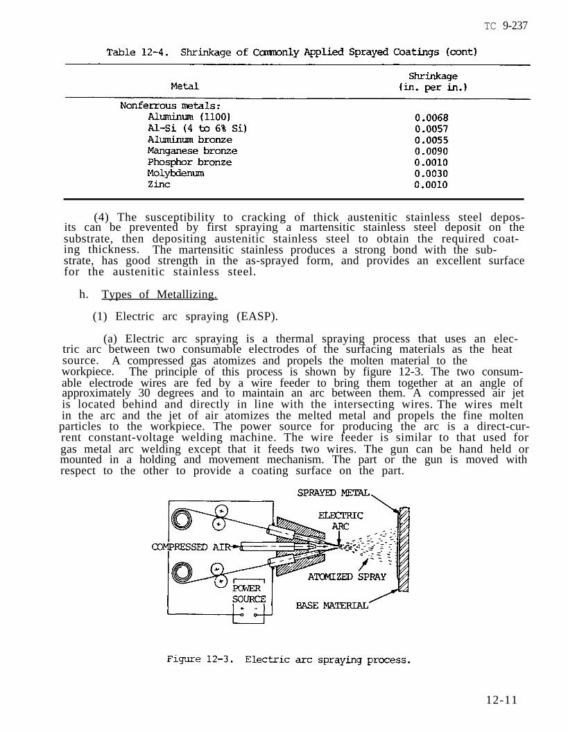
(2) Table 12-4 gives shrinkage values for the metals commonly used for spraycoatings. Thicker coatings can be deposited with metals of lower shrinkage.
(3) All sprayed-metal coatings are stressed in tension to some degree exceptin those where the substrate material has a high coefficient of expansion, and ispreheated to an approximate temperature for spraying. The stresses can cause crack-ing of thick metal coatings with a high shrinkage value;steels are in this category.
the austenitic stainless
12-10
TC 9-237
(4) The susceptibility to cracking of thick austenitic stainless steel depos-its can be prevented by first spraying a martensitic stainless steel deposit on thesubstrate, then depositing austenitic stainless steel to obtain the required coat-ing thickness. The martensitic stainless produces a strong bond with the sub-strate, has good strength in the as-sprayed form, and provides an excellent surfacefor the austenitic stainless steel.
h. Types of Metallizing.
(1) Electric arc spraying (EASP).
(a) Electric arc spraying is a thermal spraying process that uses an elec-tric arc between two consumable electrodes of the surfacing materials as the heatsource. A compressed gas atomizes and propels the molten material to theworkpiece. The principle of this process is shown by figure 12-3. The two consum-able electrode wires are fed by a wire feeder to bring them together at an angle ofapproximately 30 degrees and to maintain an arc between them. A compressed air jetis located behind and directly in line with the intersecting wires.in the arc and the jet of air atomizes the melted metal and propels the fine molten
rent constant-voltage welding machine. The wire feeder is similar to that used forgas metal arc welding except that it feeds two wires. The gun can be hand held ormounted in a holding and movement mechanism. The part or the gun is moved withrespect to the other to provide a coating surface on the part.
The wires melt
particles to the workpiece. The power source for producing the arc is a direct-cur-
12-11
TC 9-237
12-6. GENERAL (cont)
(b) The welding current ranges from 300 to 500 amperes direct current withthe voltage ranging from 25 to 35 volts. This system will deposit from 15 to 100lb/hr of metal. The amount of metal deposited depends on the current level and thetype of metal being sprayed. Wires for spraying are sized according to the Brownand Sharp wire gauge system. Normally either 14 gauge (0.064 in. or 1.626 mm) or11 gauge (0.091 in. or 2.311 mm) is used. Larger diameter wires can be used.
(c) The high temperature of the arc melts the electrode wire faster anddeposits particles having higher heat content and greater fluidity than the flamespraying process. The deposition rates are from 3 to 5 times greater and the bondstrength is greater. There is coalescence in addition to the mechanical bond. Thedeposit is more dense and coating strength is greater than when using flame spray-ing.
(d) Dry compressed air is used for atomizing and propelling the moltenmetal. A pressure of 80 psi (552 kPa) and from 30 to 80 cu ft/min (0.85 to 2.27 cum/min) is used. Almost any metal that can be drawn into a wire can be sprayed.Following are metals that are arc sprayed: aluminum, babbitt, brass, bronze, cop-per, molybdenum, Monel, nickel, stainless steel, carbon steel, tin, and zinc.
(2) Flame spraying (FLSP).
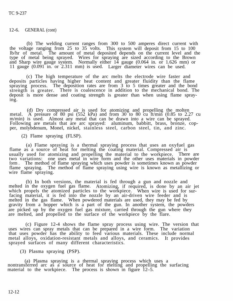
(a) Flame spraying is a thermal spraying process that uses an oxyfuel gasflame as a source of heat for melting the coating material. Compressed air isusually used for atomizing and propelling the material to the workpiece. There aretwo variations: one uses metal in wire form and the other uses materials in powderform . The method of flame spraying which uses powder is sometimes known as powderflame spraying. The method of flame spraying using wire is known as metallizing orwire flame spraying.
(b) In both versions, the material is fed through a gun and nozzle andmelted in the oxygen fuel gas flame. Atomizing, if required, is done by an air jetwhich propels the atomized particles to the workpiece. When wire is used for sur-facing material, it is fed into the nozzle by an air-driven wire feeder and ismelted in the gas flame. When powdered materials are used, they may be fed bygravity from a hopper which is a part of the gun. In another system, the powdersare picked up by the oxygen fuel gas mixture, carried through the gun where theyare melted, and propelled to the surface of the workpiece by the flare.
(c) Figure 12-4 shows the flame spray process using wire. The version thatuses wires can spray metals that can be prepared in a wire form. The variationthat uses powder has the ability to feed various materials. These include normalmetal alloys, oxidation-resistant metals and alloys, and ceramics. It providessprayed surfaces of many different characteristics.
(3) Plasma spraying (PSP).
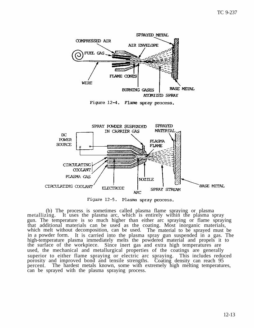
(a) Plasma spraying is a thermal spraying process which uses anontransferred arc as a source of heat for melting and propelling the surfacingmaterial to the workpiece. The process is shown in figure 12–5.
12-12
TC 9-237
(b) The process is sometimes called plasma flame spraying or plasmametallizing. It uses the plasma arc, which is entirely within the plasma spraygun. The temperature is so much higher than either arc spraying or flame sprayingthat additional materials can be used as the coating. Most inorganic materials,which melt without decomposition, can be used. The material to be sprayed must bein a powder form. It is carried into the plasma spray gun suspended in a gas. Thehigh-temperature plasma immediately melts the powdered material and propels it tothe surface of the workpiece. Since inert gas and extra high temperatures areused, the mechanical and metallurgical properties of the coatings are generallysuperior to either flame spraying or electric arc spraying. This includes reducedporosity and improved bond and tensile strengths. Coating density can reach 95percent. The hardest metals known, some with extremely high melting temperatures,can be sprayed with the plasma spraying process.
12-13
TC 9-237
12-6. GENERAL (cont)
i . The Spraying Operation. Spraying should be done immediately after the partis cleaned. If the part is not sprayed in-mediately, it should be protected fromthe atmosphere by wrapping with paper. If parts are extremely large, it may benecessary to preheat the part 200 to 400 OF (93 to 204 OC). Care must be exercisedso that heat does not build up in the workpiece. This increases the possibility ofcracking the sprayed surface. The part to be coated should be preheated to theapproximate temperature that it normally would attain during the spraying opera-tion. The distance between the spraying gun and the part is dependent on the pro-cess and material being sprayed. Recommendations of the equipment manufacturershould be followed and modified by experience. Speed and feed of spraying shouldbe uniform. The first pass should be applied as quickly as possible. Additionalcoats may be applied slcwly. It is important to maintain uniformity of temperaturethroughout the part. When there are areas of the part being sprayed where coatingis not wanted, the area can be protected by masking it with tape.
12-7. TOOLS AND EQUIPMENT
The major items of equipment used in the process, with the exception of theeutectic torch and a few fittings, are the same as in a normal oxyacetylene weldingor cutting operation. Oxygen and acetylene cylinders, cylinder-to-regulator fit-tings, pressure regulators, hoses, striker, torch and regulator wrench, tip clean-ers, and goggles are the same as those commonly used by welders. The metallizingand welding torch, its accessory tips, and the Y hose fittings are the distinctpieces of equipment used in metallizing.
12-8. METALLIZING AND WELDING TORCH
a. This torch is a manually operated, powder dispensing, oxyacetylene torch.There are three sections: the torch body, the mixing chamber and valve assembly,and the tip assembly. These assemblies are chrome plated to prolong service lifeand to prevent corrosion and contamination.
b. The torch body is also the handle. Like the body of a regular weldingtorch, it also has needle valves which control the flew of oxygen and acetylene.
c. The mixing chamber and valve assembly is the heart of the torch. In thissection, the flow of powder into the oxygen stream is controlled and mixing takesplace. A lever, like the cutting lever on a cutting torch, controls the flow ofpowdered metal. When the lever is held down, powder flows; when released, the pow–der flow is shut off. The valve and plunger are made of plastic. Should a block-age occur, no sharp or rough objects should be used to clean it. Occasionally,material will build up inside the bore. This cuts down the operating efficiency.If any malfunction occurs or is suspected, the bore is the first item to check.Just forward of the feed lever is the connection for attaching the powder bellowsmodules. It must be in the UP position while operating.
d. The tip assembly is made of a low heat-conducting alloy. It can be rotatedand locked at any position or angle from 0 to 360 degrees. The accessory tips arescrewed onto the end of the tip assembly.
12-14
TC 9-237
12-9. ACCESSORY TIPS
These tips come in three sizes, numbered 45, 48, and 53, according to the size ofthe drill number used to drill the orifice. The larger the number, the smaller thehole. A number 45 tip would be used for heavy buildup while a number 53 tip wouldbe used for fine, delicate work.
12-10. Y FI’ITINGS
Two Y fittings are provided with a set: one fitting with left-hand threads foracetylene connections and the other with right-hand threads for oxygen hose connec-tions. These fittings allow the regular welding torch to be used on the same tanksat the same time as the metallizing torch.
12-11. MATERIALS
a. General. The materials used for making welds and overlays are a littledifferent in form, but not new in purpose. Fluxes are used for hard-to-weld met-a l s . Filler metal in the form of a fine powder is used for the weld or coatingmaterial.
b. Fluxes. Two fluxes in paste form are used in combination with differentpowdered alloys. One flux is for copper only; the other is for all types of metals.
c. Welding powders. The metal powders are of high quality, specially formulat-ed alloys developed for a wide variety of jobs. These jobs range from joiningcopper to copper to putting a hard surface on a gear tooth. Selection of the prop-er alloy depends on the base metal and surface required. The powder alloys come inplastic containers called bellow modules. They are ready to insert in the connec-tion on the valve assembly after their stoppers have been removed.
12-12. SETUP
The equipment and torch are hooked up to the oxygen and acetylene tanks in the samemanner as a regular welding torch. The tip is rotated to the correct angle for thewelding position being used, and locked in place.
12-13. OPERATION
a. To operate the torch, the correct pressure setting is needed. This is deter-mined by the size of the tip being used. Tip number 45 and 48 use 25 to 30 psi(172.4 to 206.9 kPa) of oxygen and 4 to 5 psi (27.6 to 34.5 kPa) of acetylene. Tipnumber 53 uses 15 to 18 psi (103.4 to 124.1 kPa) of oxygen and 2 to 3 psi (13.8 to20.7 kPa) of acetylene.
b. After the pressures have been set, the torch is lit and adjusted to obtain aneutral flame while the alloy feed lever is depressed. This is done before joiningthe module to the torch.
c. After properdone by turning themating part locatedin place. The onlying.
flame adjustment, the module is attached to the torch. ThiS i storch upside down and inserting the end of the module into theon the valve assembly. A twist to the right locks the moduletime the torch is held upside down is during loading and unload-
17-15

TC 9-237
12-13. OPERATION (cont)
d. Before applying the powder to the surface or joint, the area must be preheat-ed. Steel is heated to a straw color while brass and copper are heated to approxi-mately 800 OF (427 OC).
e. After preheating, the powder feed lever is depressed and a thin cover ofpowder is placed over the desired surface. The lever is then released and the areaheated until the powder wets the surface or tinning action takes place. Once tin-ning is observed, the feed lever is depressed until a layer no more than 1/8 in.(3.2 mm) thick has been deposited. If more metal is desired, the area should bereheated. A light cover of powder should be applied and heated again until tinningtakes place to ensure proper bonding. In this manner, any desired thickness may beobtained while depositing the metal. The torch must be kept in a constant circularmotion to avoid overheating the metal.
f. To shut down the torch, the same procedures are followed as in regular weld-ing . Once the flame is out, the bellows module is removed by turning the torchupside down and twisting the module to the left. The plug must be replaced toprevent contamination of the alloy.
12-14. MALFUNCTIONS AND CORRECTIVE ACTIONS
As with any piece of equipment, malfunctions can occur. The orifice should bechecked first if no observable deposit is made when the feed lever is depressed.
Section IV. FLAME CUTTING STEEL AND CAST IRON
12-15. GENERAL
a. General. Plain carbon steels with a carbon content not exceeding 0.25 per-cent can be cut without special precautions. Certain steel alloys develop highresistance to the action of the cutting oxygen. This makes it difficult, and some-times impossible, to propagate the cut without the use of special techniques.
b. Oxygen cutting (OC) is a group of thermal cutting processesused to sever or remove metals by means of the chemical reaction of oxygen with thebase metal at elevated temperatures. In the case of oxidation-resistant metals,the reaction is facilitated by the use of a chemical flux or metal powder. Fivebasic processes are involved: oxyfuel gas cutting, metal powder cutting, chemicalflux cutting, oxygen lance cutting, and oxygen arc cutting. Each of these process-es is different and will be described.
Oxygen Cutting.
c. Oxyfuel Gas Cutting (OFC).
(1) Oxyfuel gas cutting severs metals with the chemical reaction of oxygenwith the base metal at elevated temperatures. The necessary temperature is main-tained by gas flames from the combustion of a fuel gas and oxygen.
(2) When an oxyfuel gas cutting operation is described, the fuel gas must bespecified. There are a number of fuel gases used. The most popular is acetylene.Natural gas is widely used, as is propane, methylacetylene-propadiene stabilized(MAPP gas), and various trade name fuel gases. Hydrogen is rarely used. Each fuelgas has particular characteristics and may require slightly different apparatus.
12-16

TC 9-237
These characteristics relate to the flame temperatures, heat content, oxygen fuelgas ratios, etc.
(3) The general concept of oxyfuel gas cutting is similar no matter what fuelgas is used. It is the oxygen jet that makes the cut in steel, and cutting speeddepends on how efficiently the oxygen reacts with the steel.
(4) Heat is used to bring the base metal steel up to kindling temperaturewhere it will ignite and burn in an atmosphere of pure oxygen. The chemical formu-las for three of the oxidation reactions is as follows:
(5) At elevated temperatures, all of the iron oxides are produced in thecutting zone.
(6) The oxyacetylene cutting torch is used to heat steel by increasing thetemperature to its kindling point and then introducing a stream of pure oxygen tocreate the burning or rapid oxidation of the steel. The stream of oxygen alsoassists in removing the material from the cut. This is shown by figure 12-6.
(7) Steel and a number of other metals are flame cut with the oxyfuel gascutting process. The following conditions must apply:
(a) The melting point of the material must be above its kindling tempera-ture in oxygen.
(b) The oxides of the metal should melt at a lower temperature than themetal itself and below the temperature that is developed by cutting.
12-17

TC 9-237
12-15. GENERAL (cont)
(c) The heat produced by the combustion of the metal with oxygen must besufficient to maintain the oxygen cutting operation.
(d) The thermal conductivity must be low enough so that the material can bebrought to its kindling temperature.
(e) The oxides formed in cutting should be fluid when molten so the cuttingoperation is not interrupted.
(8) Iron and low-carbon steel fit all of these requirements and are readilyoxygen flame cut. Cast iron is not readily flame cut, because the kindling tempera-ture is above the melting point. It also has a refractory silicate oxide whichproduces a slag covering. Chrome-nickel stainless steels cannot be flame cut withthe normal technique because of the refractory chromium oxide formed on the sur-face. Nonferrous metals such as copper and aluminum have refractory oxide cover-ings which prohibit normal oxygen flame cutting. They have high thermal conductivi-ty.
(9) When flame cutting, the preheating flame should be neutral or oxidizing.A reducing or carbonizing flame should not be used. The schedule for flame cuttingclean mild steel is shown by the table 12-5.
(10) Torches are available for either welding or cutting. By placing thecutting torch attachment on the torch body it is used for manual flare cutting.Figure 12-7 shows a manual oxyacetylene flare-cutting torch. Various sizes of tipscan be used fordardized. Most
12-18
manual flame cutting. The numbering system for tips is not stan-manufacturers use their own tip number system. Each system is,

TC 9-237
however, based on the size of the oxygen cutting orifice of the tip. These arerelated to drill sizes. Different tip sizes are required for cutting differentthicknesses of carbon steel.
(11) For automatic cutting with mechanized travel, the same types of tips canbe used. High-speed type tips with a specially shaped oxygen orifice provide forhigher-speed cutting and are normally used. The schedule shown in table 12-5 pro-vides cutting speeds with normal tips; the speeds can be increased 25 to 50 percentwhen using high speed tips.
(12) Automatic shape-cutting machines are widely used by the metalworkingindustry. These machines can carry several torches and cut a number of piecessimultaneously. Multitorch cutting machines are directed by numerically-controlledequipment. Regardless of the tracing control system is used, the cutting operationis essentially the same.
(13) One of the newer advances in automatic flame cutting is theof bevel cuts on contour-shaped parts. This breakthrough has made theically controlled oxygen cutting equipment even more productive.
generationuse of numer-
(14) Many specialized automatic oxygen cutting machines are available forspecific purposes. Special machines are available for cutting sprockets and otherprecise items. Oxygen-cutting machines are available for cutting pipe to fit otherpipe at different angles and of different diameters. These are quite complex andhave built-in contour templates to accommodate different cuts and bevels on thepipe. Other types of machines are designed for cutting holes in drum heads, testspecimens, etc. Two or three torches can be used to prepare groove bevels forstraight line cuts as shown by figure 12–8. Extremely smooth oxygen-cut surfacescan be produced when schedules are followed and all equipment is not in properoperating condition.
12-19
TC 9-237
12-15. GENERAL (cont)
d. Metal Powder Cutting (POC).
(1) Metal powder cutting severs metals through the use of powder to facili-tate cutting. This process is used for cutting cast iron, chrome nickel stainlesssteels, and some high-alloy steels.
(2) The process uses finely divided materialthe cutting-oxygen stream.
, usually iron powder, added toThe powder is heated as it passes through the oxy-
acetylene preheat flames and almost immediately oxidizes in the stream of the cut-ting oxygen. A special apparatus to carry the powder to the cutting tip must beadded to the torch. A powder dispenser is also required. Compressed air is usedto carry the powder to the torch.
(3) The oxidation, or burning of the iron powder, provides a much highertemperate in the oxygen stream. The chemical reaction in the flame allows thecutting-oxygen stream to oxidize the metal being cut continuously in the same man-ner as when cutting carbon steels.
(4) With the use of iron powder in the oxygen stream, it is possible to startcuts without preheating the base material.
(5) Powder cutting has found its broadest use in the cutting of cast iron andstainless steel. It is used for removing gates and risers from iron and stainlesssteel castings.
(6) Cutting speeds and cutting oxygen-pressures are similar to those usedwhen cutting carbon steels. For heavier material over 1 in. (25 mm) thick, a noz-zle one size larger should be used. Powder flow requirements vary from 1/4 to 1/2lb (0.11 to 0.23 kg) of iron powder per minute of cutting. Powder tends to leave ascale on the cut surface which can easily be removed as the surface cools. This isa rather special application process and is used only where required.
(7) Stack cutting is the oxygen cutting of stacked metal sheets or platesarranged so that all the plates are severed by a single cut. In this way, thetotal thickmess of the stack is considered the same as the equivalent thickness ofa solid piece of metal. When stack cutting, particularly thicker material, the cutis often lost because the adjoining plates may not be in intimate contact with eachother. The preheat may not be sufficient on the lower plate to bring it to thekindling temperature and therefore the oxygen stream will not cut through the re-maining portion of the stack. One way to overcome this problem is to use the metalpowder cutting process. By means of the metal powder and its reaction in the oxy-gen, the cut is completed across separations between adjacent plates.
e. Chemical Flux Cutting (FOC). Chemical flux cutting is an oxygen-cuttingprocess in which metals are severed using a chemical flux to facilitate cutting.Powdered chemicals are utilized in the same way as iron powder is used in the metalpowder cutting process. This process is sometimes called flux injection cutting.Flux is introduced into the cut to combine with the refractory oxides and make thema soluble compound. The chemical fluxes may be salts of sodium such as sodiumcarbonate. Chemical flux cutting is of minor industrial significance.
12-20
TC 9-237
f . Oxygen Lance Cutting (LOC).
(1) Oxygen lance cutting severs metals with oxygen supplied through a consum-able tube. The preheat is obtained by other means. This is sometimes called oxy-gen lancing. The oxygen lance is a length of pipe or tubing used to carry oxygento the point of cutting. The oxygen lance is a small (1/8 or 1/4 in. (3.2 or 6.4mm) nominal) black iron pipe connected to a suitable handle which contains a shut-off valve. This handle is connected to the oxygen supply hose. The main differ-ence between the oxygen lance and an ordinary flame cutting torch is that there isno preheat flame to maintain the material at the kindling temperature. The lanceis consumed as it makes a cut. The principle use of the oxygen lance is the cut-ting of hot metal in steel mills. The steel is sufficiently heated so that theoxygen will cause rapid oxidation and cutting to occur. For other heavy or deepcuts, a standard torch is used to bring the surface of the metal to kindling temper-ature. The oxygen lance becomes hot and supplies iron to the reaction to maintainthe high temperature.
(2) There are several proprietary specialized oxygen lance type cutting barsor pipes. In these systems, the pipe is filled with wires which may be aluminumand steel or magnesium and steel. The aluminum and magnesium readily oxidize andincrease the temperature of the reaction. The steel of the pipe and the steelwires will tend to slow down the reaction whereas the aluminum or magnesium wirestend to speed up the reaction. This type of apparatus will burn in air, underwater, or in noncombustible materials. The tremendous heat produced is sufficientto melt concrete, bricks, and other nonmetals. These devices can be used to severconcrete or masonry walls and will cut almost anything.
g.. Oxygen Arc Cutting (AOC) .
(1) Oxygen arc cutting severs metals by means of the chemical reaction ofoxygen with the base metal at elevated temperatures. The necessary temperature ismaintained by means of an arc between a consumable tubular electrode and the basemetal.
(2) This process requires a specialized combination electrode holder andoxygen torch. A conventional constant current welding machine and special tubularcovered electrodes are used.
(3) This process will cut high chrome nickel stainless steels, high-alloysteels, and nonferrous metals.
(4) The high temperature heat source is an arc between the special coveredtubular electrode and the metal to be cut. As soon as the arc is established, avalve on the electrode holder is depressed. Oxygen is introduced through the tubu-lar electrode to the arc. The oxygen causes the material to burn and the streamhelps remove the material from the cut. Steel from the electrode plus the fluxfrom the covering assist in making the cut. They combine with the oxides and cre-ate so much heat that thermal conductivity cannot remove the heat quickly enough toextinguish the oxidation reaction.
12-21

TC 9-237
12-15. GENERAL (cont)
(5) This process will routinely cut aluminum, copper, brasses, bronzes,Monel, Inconel, nickel, cast iron, stainless steel, and high-alloy steels. Thequality of the cut is not as gocd as the quality of an oxygen cut on mild steel,but sufficient for many applications. Material from 1/4 to 3 in. (6.4 to 76 mm)can be cut with the process. The electric current ranges from 150 to 250 amperesand oxygen pressure of 3 to 60 psi (20.7 to 413.7 kPa) may be used. Electrodes arenormally 3/16 in. (4.8 mm) in diameter and 18 in. (457 mm) long. They are suitablefor ac or dc use. This process is used for salvage work, as well as for manufactur-ing and maintenance operations.
12-16. HIGH CARBON STEELS
The action of the cutting torch on high carbon steels is similar to flame hardeningprocesses. The metal adjacent to the cutting area is hardened by being heatedabove its critical temperature and quenched by the adjacent mass of cold metal.This condition can be minimized by preheating the part from 500 to 600 OF (260 to316 OC) before the cut is made.
12-17. WASTER PLATE ALLOY STEEL
The cutting action on an alloy steel that is difficult to cut can be improved byclamping a mild steel “waster plate” tightly to the upper surface and cuttingthrough both thicknesses. This waster plate method will cause a noticeable improve-ment in the cutting action. The molten steel dilutes or reduces the alloying con-tent of the base metal.
12-18. CHROMIUM AND STAINLESS STEEL
These and other alloy steels that previously could be cut only by a melting actioncan now be cut by rapid oxidation. This is done by introducing iron powder or aspecial nonmetallic powdered flux into the cutting oxygen stream. The iron powderoxidizes quickly and liberates a large quantity of heat. This high heat melts therefractory oxides which normally protect the alloy steel from the action of oxy-gen . These molten oxides are flushed from the cutting face by the oxygen blast.The cutting oxygen is able to continue its reaction with the iron powder and cutits way through the steel plates. The nonmetallic flux, when introduced into thecutting oxygen stream, combines chemically with the refractory oxides. This produc-es a slag of a lower melting point, which is washed or eroded out of the cut, expos-ing the steel to the action of the cutting oxygen.
12-19. CAST IRON
Cast iron melts at a temperature lower than its oxides. Therefore, in the cuttingoperation, the iron tends to melt rather than oxidize. For this reason, the oxygenjet is used to wash out and erode the molten metal when cast iron is being cut. Tomake this action effective, the cast iron must be preheated to a high temperatureand much heat must be liberated deep in the cut. This is effected by adjusting thepreheating flames so there is an excess of acetylene. The length of the acetylenestreamer and the procedure for advancing the cut are shown in figure 12-9. The useof a mild iron flux to maintain a high temperature in the deeper recesses of thecut is also effective (fig. 12–9).
12-22

TC 9-237
12-23

TC 9-237
Section V. FLAME TREATING METAL
12-20. FLAME HARDENING
a. The oxyacetylene flame can be used to harden the surface of hardenables t e e l , including stainless steels, to provide better wearing qualities. The car-bon content of the steel should be 0.35 percent or higher for appreciable harden-ing. The best range for the hardening process is 0.40 to 0.50 percent. In thisprocess, the steel is heated to its critical temperature and then quenched, usuallywith water. Steels containing 0.70 percent carbon or higher can be treated in thesame manner, except that compressed air or water sprayed by compressed air, is usedto quench the parts less rapidly to prevent surface checking. Oil is used forquenching some steel compositions.
b. The oxyacetylene flame is used merely as a heat source and involves nochange in the compsition of the steels as in case hardening where carbon or nitro-gen is introduced into the surface. In case hardening, the thickness of the hard-ened area ranges from 0 to 0.020 in. (0 to 0.508 mm).
c. Ordinary welding torches are used for small work, but for most flame harden–ing work, water-cooled torches are necessary. Tips or burners are of the multi-flame type. They are water cooled since they must operate for extended periodswithout backfiring. Where limited areas are to be hardened, the torch is movedback and forth over the part until the area is heated above the critical tempera-ture. Then the area is quenched. The hardening of extended areas is accomplishedby steel hardening devices. These consist of a row of flames followed by a row ofquenching jets. A means of moving these elements over the surface of the work, ormoving the work at the required speed under the flames and jets, is also required.
12-21. FLAME SOFTENING
a. Certain steels, called six-hardening steels, will become hard and brittlewhen cooled rapidly in the air from a red hot condition. This hardening actionfrequently occurs when the steels are flame cut or arc welded. When subsequentmachining is required, the hardness must be decreased to permit easier removal ofthe metal.
b. Oxyacetylene flames adjusted to neutral can be used either to prevent harden-ing or to soften an already hardened surface. The action of the flame is used torapidly heat the metal to its critical temperature. However, in flare softening,the quench is omitted and the part is cooled slowly, either by still air or byshielding with an insulating material.
c. Standard type torches, tips, and heating heads, like those used for weldingequipment, are not applicable. The equipment used in flame hardening is necessary.
12-22. FLAME STRAIGHTENING
a. It is often desirable or necessary to straighten steel that has been expand-ed or distorted from its original shape by uneven heating. This is especially trueif the steel is prevented from expanding by adjacent cold metal. The contractionon cooling tends to shorten the surface dimension on the heated side of the plate.Since some of the metal has been upset permanently, the plate cannot return to itsoriginal dimensions and becomes dished or otherwise distorted.
12-24
TC 9-237
b. Localized heat causes such metal distortion. This principle can be used toremedy warpage, buckling, and other irregularities in plates, shafts, structuralmembers, and other parts. The distorted areas are heated locally and then quenchedon cooling. The raised sections of the metal will be drawn down. By repeatingthis process and carefully applying heat in the proper areas and surfaces, irregu-larities can be remedied.
12-23. FLAME STRENGTHENING
Flame strengthening differs from flame hardening. The intent is to locallystrengthen parts that will have to withstand severe service conditions. This pro-cess is used particularly for parts that are subjected to frequently varying stress-es that lead to fatigue failure. The section that is to be strengthened is heatedto the hardening temperature with the oxyacetylene flame, then quenched either withwater, a water-air mixture, or air, depending on the composition of the steel beingtreated.
12-24. FLAME DESCALING
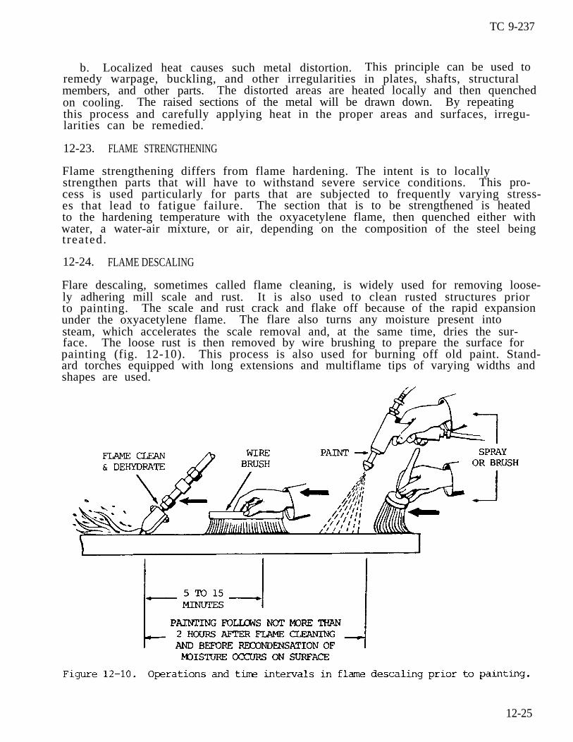
Flare descaling, sometimes called flame cleaning, is widely used for removing loose-ly adhering mill scale and rust. It is also used to clean rusted structures priorto painting. The scale and rust crack and flake off because of the rapid expansionunder the oxyacetylene flame. The flare also turns any moisture present intosteam, which accelerates the scale removal and, at the same time, dries the sur-face. The loose rust is then removed by wire brushing to prepare the surface forpainting (fig. 12-10). This process is also used for burning off old paint. Stand-ard torches equipped with long extensions and multiflame tips of varying widths andshapes are used.
12-25

TC 9-237
12-25. FLAME MACHINING (OXYGEN MACHINING)
a.wherea ls .
b.
General. Flame machining. or oxygen machining, includes those processesoxygen and an oxyacetylene flare are used in removing the surfaces of met-Several of these processes are described below.
Scarfing or Deseaming. This process is used for the removal of cracks,scale, and other defects frcm the surface of blooms, billets, and other unfinishedshapes in steel mills. In this process, an area on the surface of the metal isheated to the ignition temperature. Then, a jet or jets of oxygen are applied to the preheated area and advanced as the surface is cut away. The scarfed surface iscomparable to that of steel cleaned by chipping.
c “ G o u g i n g . This process is used for the removal of welds. It is also used inthe elimination of defects such as cracks, sand inclusions, and porosity from steelcastings.
d. Hogging. This is a flame machining process used for the removal of excessmetals, such as risers and sprues, from castings. It is a combination of scarfingand gouging techniques.
mechanical turning with the substitution of a cutting torch in place of the usualcutting tool.
f . Surface Planing. Surface planing is a type of flame machining similar tomechanical planing. The metal is removed from flat or round surfaces by a seriesof parallel and overlapping grooves. Cutting tips with special cutting orificesare used in this operation. The operator controls the width and depth of the cutby controlling the oxygen pressure, the tip angle with relation to the metal sur-face, and the speed with which the cutting progresses.
12-26. OXYACETYLENE RIVET CUTTING
a. Removal of Countersunk Rivets.
(1) When countersunk rivets are being removed, the cutting torch is held sothat the cutting nozzle is perpendicular to the plate surface (fig. 12-11). Thepreheating flames are directed at a point slightly below the center of the rivet
e. Oxygen Turning. This flame machining process is identical in principle to
head. The tips of the inner(1.6 mm) away from the rivet
cones of the flames should be approximately 1/16 in. h e a d .
12-26
TC 9-237
(2) When the area of the rivet head under the flames becomes bright red, thetip of the torch is raised slightly to direct the cutting oxygen stream to theheated area. The cutting oxygen valve is opened. The torch shield is held steadyuntil the coned head has been burned through and the body or shank of the rivet isreached. The remainder of the head should then be removed in one circular, wipingmotion. The torch should be held with the cutting oxygen stream pointed at thebase of the countersink, and then moved once around the circumference. After thehead has been removed, the shank can be driven out.
b. Removal of Buttonhead Rivets.
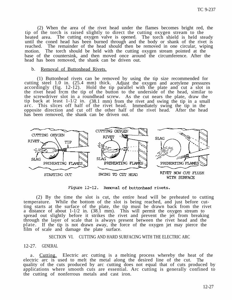
(1) Buttonhead rivets can be removed by using the tip size recommended forcutting steel 1.0 in. (25.4 mm) thick. Adjust the oxygen and acetylene pressuresaccordingly (fig. 12-12). Hold the tip parallel with the plate and cut a slot inthe rivet head frcm the tip of the button to the underside of the head, similar tothe screwdriver slot in a roundhead screw. As the cut nears the plate, draw thetip back at least 1-1/2 in. (38.1 mm) from the rivet and swing the tip in a smallarc. This slices off half of the rivet head. Immediately swing the tip in theopposite direction and cut off the other half of the rivet head. After the headhas been removed, the shank can be driven out.
(2) By the time the slot is cut, the entire head will be preheated to cuttingtemperature. While the bottom of the slot is being reached, and just before cut-ting starts at the surface of the plate, the tip must be drawn back from the riveta distance of about 1-1/2 in. (38.1 mm). This will permit the oxygen stream tospread out slightly before it strikes the rivet and prevent the jet from breakingthroughplate.film of
12-27.
the layer of scale that is always present between the rivet head and theIf the tip is not drawn away, the force of the oxygen jet may pierce thescale and damage the plate surface.
SECTION VI. CUTTING AND HARD SURFACING WITH THE ELECTRIC ARC
GENERAL
a . Cutting. Electric arc cutting is a melting process whereby the heat of theelectric arc is used to melt the metal along the desired line of the cut. Thequality of the cuts produced by arc cutting does not equal that of cuts produced byapplications where smooth cuts are essential. Arc cutting is generally confined tothe cutting of nonferrous metals and cast iron.
12-27
TC 9-237
12-27. GENERAL (cont)
b. Hard Surfacing. Hard surfacing is the process of applying extremely hardalloys to the surface of a softer metal to increase its resistance to wear by abra–sion, corrosion, or impact. The wearing surfaces of drills, bits, cutters, orother parts, when treated with these special alloys, will outwear ordinary steelparts from 2 to 25 times. This will depend on the hard surfacing alloy and theservice to which the part is subjected.
12-28. METAL CUTTING WITH ELECTRIC ARC
a. General. Electric arc cutting can be performed by three methods: carbon-arc, metal-arc, and arc-oxygen.
b. Carbon-Arc Cutting. In carbon-arc cutting, a carbon electrode is utilizedto melt the metal progressively by maintaining a steady arc length and a uniformcutting speed. Direct current straight polarity is preferred, because it developsa higher heat at the base metal, which is the positive pole. Direct current alsopermits a higher cutting rate than alternating current, with easier control of thearc. Air cooled electrode holders are used for currents up to 300 amperes. Watercooled electrode holders are desirable for currents in excess of 300 amperes.
c. Metal-Arc Cutting.
(1) Metal-arc. Metal-arc cutting is a progressive operation with a low car-bon steel, covered electrode. The covering on the electrode is a non-conductingrefractory material. It permits the electrode to be inserted into the gap of thecut without being short circuited. This insulating coating also stabilizes andintensifies the action of the arc. Direct current straight polarity is preferred,but alternating current can be used. Standard electrode holders are applicable formetal-arc cutting in air.
(2) Air-arc. By slightly converting the standard electrode holder, as de-scribed in TB 9-3429-203/1, a stream of air can be directed to the surface of thework, increasing the speed of the cut and holding it to a minimum width.
(3) Underwater cutting. Specially constructed, fully insulated holders mustbe used for underwater metal-arc cutting.
d. Arc-Oxygen Cutting. Arc-oxygen cutting is a progressive operation in whicha tubular electrode is employed. The steel or conducting-type ceramic electrode isused to maintain the arc and series as a conduit through which oxygen is fed intothe cut. In this process, the arc provides the heat and the oxygen reacts with themetal in the same manner as in oxyacetylene cutting. Both direct and alternatingcurrents are applicable in this process.
12-29. HARD SURFACING
Hard surfacing is used to apply a layer of metal of a special composition onto thesurface of metal of a special composition onto the surface or to a specific sectionor part of a base metal of another composition. A wide variety of characteristicsor performance characteristicsmetals. The applied layer mayrequired.
can be secured by the selection-of proper surfacingbe as thin as 1/32 in. (0.79 mm) or as thick as
12-28
TC 9-237
12-30. METALS THAT CAN BE HARD SURFACED
a. All plain carbon steels with carbon content up to 0.50 percent can be hardsurfaced by either the oxyacetylene or electric arc process.
b. High carbon steels containing more than O.5O percent carbon can be hardsurfaced by any of the arc welding processes. However, preheating to between 300and 600 OF (149 and 316 OC) is usually advisable. This preheating will preventcracking due to sudden heating of hardened parts. It will also prevent excessivehardening and cracking of the heat affected zone during cooling.
c . Low alloy steels can be hard surfaced in the same manner as plain carbonsteels of the same hardenability if the steel is not in its hardened state. If itis in the hardened state, it should be annealed before welding. In some cases,heat treatment is required after welding.
d. The hard surfacing of high speed steels is not generally recommended. Thisis due to the fact that, regardless of heat treatment, brittleness and shrinkagecracks will develop in the base metal after hard surfacing. Usually there is noneed for hard surfacing these steels because surfaced parts of low alloy steelsshould provide equal service characteristics.
.
e . Manganese (Hadfield) steels should be hard surfaced by the shielded metal-arc process only, using the work hardening type of alloys or with alloys that willbond easily with this metal.
f . Stainless steels, includinq the high chrome and the 18-8 chrome-nickelsteels, can be hard surfaced with most of-the alloys that have suitable meltingpoints. A knowledge of the composition of the stainless steel at hand is neededfor the selection of the proper alloy. Otherwise, brittleness or impairment ofcorrosion resistance may result. The high coefficient of expansion of the 18-8steels must also be considered.
g. Gray and alloy cast irons can be hard surfaced with the lower melting pointalloys and the austenitic alloys. However, precautions need to be taken to preventcracking of the cast iron during and after welding. Cobalt base alloys are alsoapplicable to cast iron, although a flux may need to be applied to the cast iron.
h. White cast iron cannot be successfully surfaced because the welding heatmaterially alters the properties of the underlying metal.
i . Malleable iron can be surfaced in the same manner as cast iron.
j . Copper, brass, and bronze are difficult to surface with ferrous or highalloy nonferrous metals because of the low melting points. However, brass, bronze,and some nickel surfacing alloys can be applied very readily. Fluxes are usuallyneeded in these applications to secure sound welds.
12-31. ALIOYS USED FOR HARD SURFACING
a. General. No single hard surfacing material is suitable for all applica-tions. Many types of hard surfacing alloys have been developed to meet the variousrequirements for hardness, toughness, shock and wear resistance, and other specialquali t ies. These alloys are classified into six groups and are described below.
12-29
TC 9-237
12-31. ALLOYS USED FOR HARD SURFACING (cont)
b. Group A. These include the low alloy types of surfacing alloys that are airhardened. Most of these electrodes are covered with coatings that supply alloying,deoxidizing, and arc stabilizing elements. Preheating of the base metal may benecessary to prevent cracking when harder types of electrodes are used, but in manyapplications the presence of small cracks is not important.
c. Group B. These electrodes include the medium alloy and medium-high alloytypes. They have a light coating for arc stabilization only. The alloying agentsare in the metal of the rod or wire. The electodes in this group have a lowermelting point than those in group A. They produce a flatter surface and must beused in the flat position only. Multilayer deposits, with proper preheat, shouldbe free from cracks.
d. Group C. These electrodes include the high speed steel and austenitic steelalloys (other than austenitic manganese steels). The electrodes are either bare orhave a light arc stabilizing coating. The bare electodes should be only used forsurfacing manganese steels because their arc characteristics are poor. To avoidembrittlement of the weld metal, the base metal must not be heated over 700 OF(371 OC). Peening is used in the application of these alloys to reduce stressesand to induce some hardness in the underlying layers.
e. Group D. These electrodes include the cobalt base alloys. They have amoderately heavy coating and are intended for manual welding only. To avoid impair-ment of metal properties, low welding heat is recommended. Deposits are subject tocracking but this can be prevented by preheating and slow cooling of the workpiece.
f. Group E. These alloys are supplied as tube rods containing granular tung-sten carbide inside the tube. Their arc characteristics are poor but porosity andcracks are of little importance in the application for which they are intended.The tungsten carbide granules must not be melted or dissolved in the steel. Forthis reason, a minimum heat is recommended for welding. The deposits should show aconsiderable amount of undissolved cubicle particles.
g. Group F. These are nonferrous alloys of copper and nickel base types. Theyare heavily coated and are intended for direct current reverse polarity welding inthe flat position only.
12-32. HARD SURFACING PROCEDURE
a. Preparation of Surface. The surface of the metal to be hard surfaced mustbe cleaned of all scale, rust, dirt, or other foreign substances by grinding, ma–chining, or chipping. If these methods are not practicable, the surface may beprepared by filing, wire brushing, or sandblasting. The latter methods sometimesleave scale or other foreign matter which must be floated out during the surfacingoperation. All edges of grooves, corners , or recesses must be well rounded toprevent overheating of the base metal.
b. Hard Surfacing with the Metal Arc. Surfacing by arc welding is done in thesame manner and is similar in principle to joining by arc welding, except that theadded metal has a composition that is not the same as that of the base metal. Thecharacteristics of the added metal would be changed or impaired if it were exces–sively diluted by or blended with the base metal. For this reason, penetration
12-30

into the base metal should be restricted by applying the surfacing metal with theminimum welding heat. In general, the current, voltage, polarity, and other condi-
TC 9-237
tions recommended by the manufacturer of the electrodes are based on this factor.An arc as long as possible will give the best results.
c. Hard Surfacing with the Carbon Arc. This process is used principally forthe application of group F alloys. The welding machine is set for straight polari-ty and-the heat of the arc is used to weld the-particlesof the base metal.
Section VII. ARMOR PLATE WELDING AND
12-33. GENERAL
of carbide to the surface
CUTTING
a. Armor plate is used for the protection of personnel and equipment in combattanks, self propelled guns, and other combat vehicles against the destructive forc-es of enemy projectiles. It is fabricated in the forms of castings and rolledplates. These are selectively heat treated, in turn, to develop the desired struc-tural and protective properties. Industrial manufacture of gun turrets and combattank hulls includes designs using one-piece castings and welded assemblies of castsections and rolled plates. In certain cases, cast sections of armor are bolted inplace to expedite the requirements of maintenance through unit replacement. Weld-ing has replaced riveting as a formative process of structural armor fabrication.Riveting, however, is still used on some vehicles protected by face hardened armor.
b. The development of a suitable technique for welding armor plate is contin-gent upon a clear understanding of the factors affecting the weldability of armorplates, the structural soundness of the weld, and its ultimate ability to withstandthe forces of impact and penetration in service. From the standpoint of field re-pair by welding, these considerations can be resolved into the factors outlinedhelm:
(1) Knowledge of the exact type of armor being welded through suitable identi-fication tests.
(2) Knowledge of alternate repair methods which are satisfactory for theparticular type of armor and type of defect in question.
(3) Design function of the damaged structure.
(4) Selection of welding materials and repair procedures from the facilitiesavailable to produce optimum protective properties and structural strength.
(5) Determination of the need for emergency repair to meettion.
(6) Careful analysis of the particular defect in the armordisposition of the variables listed below:
(a) Joint preparation and design.
(b) Welding electrodes.
(c) Welding current, voltage, and polarity.
the existing situa-
to ensure proper
12-31
TC 9-237
12-33. GENERAL (cont)
(d) Sequence of welding passes.
(e) Welding stresses and warpage.
(f) Proper protection or removal of flammable materials and equipment inthe vicinity of the welding operation.
c. The advantages of welding as an expedient for field repair to damaged armorplate lie principally in the speed and ease with which the operation can be per-formed. The welding procedures for making repairs in the field are basically thesame as those used for industrial fabrication. They must be modified at timesbecause of the varying types of damage due to impact, such as the following:
(1) Complete shell penetration.
(2) Bulges or displaced sections.
(3) Surface gouges.
(4) Linear cracks of various widths terminating in the armor or extending toits outside edges.
(5) Linear or transverse cracks in or adjacent to welded seams.
d. Many repairs made by welding require the selective use of patches obtainedby cutting sections from completely disabled armored vehicles having similar armorplate. Also, most of the welding, whether around patches or along linear seams, isperformed under conditions that frequently will permit no motion of the base metalsections to yield under contraction stresses produced by the cooling weld metal.The stress problem is further complicated by stresses produced by projectiles physi-cally drifting the edges of the armor at the point of impact or penetration. It iswith all these variables in mind that the subsequent plate welding procedures aredetermined.
12-34. PROPERTIES OR ARMOR PLATE
Armor plate is an air hardening alloy steel , which means that it will harden bynormalizing or heating to its upper critical point and cooling in still air. Thebase metal quenching effect produced adjacent to a weld in heavy armor plate undernormal welding conditions is about halfway between the effects of air cooling andoil quenching. The extremely steep thermal gradients occuring in the region of aweld range from temperatures of 3000 OF (1649 OC) or more in the weld metal to theoriginal temperature of the base metal. Therefore, a narrow zone on each side ofthe deposited weld metal is heated above its critical temperature by the weldingheat and quenched by the relatively cold base metal to form a hard brittle zone.It is in this hard, nonductile formation, known as martensite, that cracks are morelikely to occur as a result of the sudden application of load. For this reason,special precautions must be taken in all welding operations to minimize the forma-tion of these hard zones and to limit their effect on the structural properties ofthe welded armor. Care must be taken to prevent rapid cooling of the armor afterwelding in order to avoid the formation of cracks in these hard zones.
12-32

TC 9-237
12-35. TYPES OF ARMOR PLATE
a. General. Two types of armor are used on combat vehicles: homogeneous (castor rolled) and face hardened (rolled). It is essential that the armor be specifi-cally identified before any welding or cutting operations are performed. This isimportant because the welding procedures for each type of armor are distinctlydifferent and noninterchangeable.
b. Homogeneous Armor. Homogeneous armor is heat treated through its entirethickness to develop good shock or impact resisting properties. As its name indi-cates, it is uniform in hardness, composition, and structure throughout and can bewelded on either side. Aluminum armor plate is in the homogeneous class and weld-ing procedures are the same as gas metal-arc welding (para 10-12, p 10-54).
c. Face Hardened Armor Plate. Face hardened armor plate has an extremely hardsurface layer, obtained by carburizing, which extends to a depth of 1/5 to 1/4 ofthe outward facing thickness of the armor on the tank or armored vehicle. Theprimary purpose of face hardened armor is to provide good resistance to penetra-tion. The inner side is comparatively soft and has properties similar to those ofhomogeneous armor. The inside and outside of face hardened armor plate are twodifferent kinds of steel. Face hardened steel UP to 0.5 in. (12.7 mm) in thicknessshould be welded from the soft side only.
12-36. IDENTIFICATION OF ARMOR PLATE
a. File Test. This test is a simple but accurateplate. A file will bite into homogeneous armor platebite into the soft side of face hardened armor plate.
method of identifying armoron both sides, but will onlyWhen applied to the face. .
side, the file will slip, acting in much the same manner as on case hardened steel.
b. Appearance of Fracture. The metal edges of holes or cracks in homogeneousarmor plate are ragged and bent, with the metal drifted in the direction of theforces which damaged the armor. Cracks in homogeneous armor are usually caused bystresses and are present at severe bulges or bends in the plate or section. Themetal edges of holes and cracks in face hardened armor are relatively clean cut andsharp. The plates do not bulge to any great extent before cracking. By examiningthe edges of freshly broken face hardened armor, it can be noted that the metal atthe face side is brighter and finer in structure than the metal at the soft side.The brighter metal extends to a depth of approximately 1/5 to 1/4 of the thicknessfrom the surface of the side.
12-37. CUTTING ARMOR PLATE
a. Cutting Homogeneous Armor Plate. Either the oxygen cutting torch, which ispreferable, or the electric arc can be used to cut homogeneous armor plate. Thecarbon arc can be used to cut out welds and to cut castings and plates, but theshielded metal-arc is preferred when oxygen and acetylene are not available.
b. Cutting Face Hardened Armor Plate.
(1) General. The procedure for cutting this type of armor is essentially thesame as that required for homogeneous armor except that every precaution should betaken to keep as much heat as possible away from the hard face side of the plate.This is accomplishd by performing all cutting operations from the soft side of thearmor, thus limiting the extent of heating and consequent softening of the hardenedsurfaces.
12-33
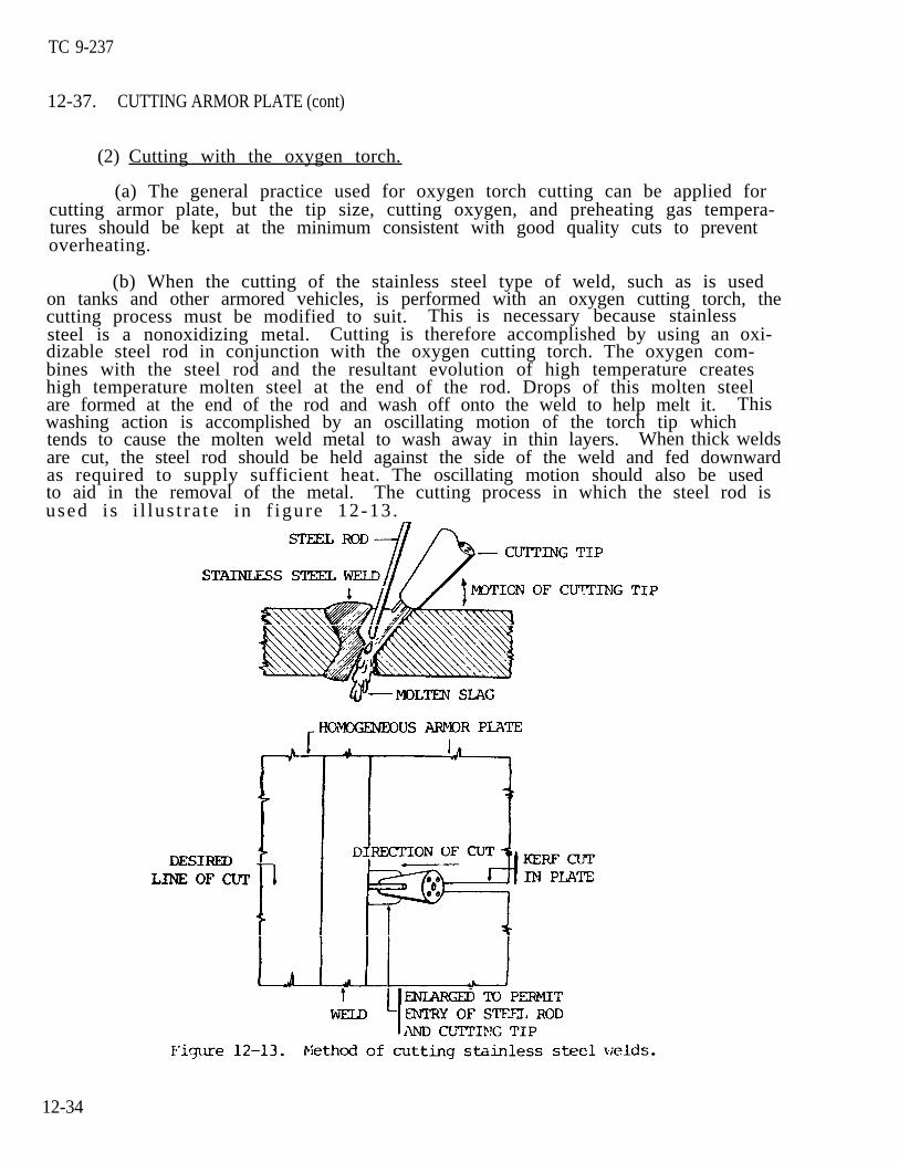
TC 9-237
12-37. CUTTING ARMOR PLATE (cont)
(2) Cutting with the oxygen torch.
(a) The general practice used for oxygen torch cutting can be applied forcutting armor plate, but the tip size, cutting oxygen, and preheating gas tempera-tures should be kept at the minimum consistent with good quality cuts to preventoverheating.
(b) When the cutting of the stainless steel type of weld, such as is usedon tanks and other armored vehicles, is performed with an oxygen cutting torch, thecutting process must be modified to suit. This is necessary because stainlesssteel is a nonoxidizing metal. Cutting is therefore accomplished by using an oxi-dizable steel rod in conjunction with the oxygen cutting torch. The oxygen com-bines with the steel rod and the resultant evolution of high temperature createshigh temperature molten steel at the end of the rod. Drops of this molten steelare formed at the end of the rod and wash off onto the weld to help melt it. Thiswashing action is accomplished by an oscillating motion of the torch tip whichtends to cause the molten weld metal to wash away in thin layers. When thick weldsare cut, the steel rod should be held against the side of the weld and fed downwardas required to supply sufficient heat. The oscillating motion should also be usedto aid in the removal of the metal. The cutting process in which the steel rod isused i s i l lus t ra te in f igure 12-13 .
12-34
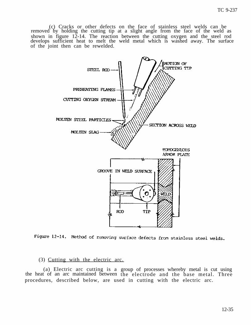
TC 9-237
(c) Cracks or other defects on the face of stainless steel welds can beremoved by holding the cutting tip at a slight angle from the face of the weld asshown in figure 12-14. The reaction between the cutting oxygen and the steel roddevelops sufficient heat to melt the weld metal which is washed away. The surfaceof the joint then can be rewelded.
(3) Cutting with the electric arc.
(a) Electric arc cutting is athe heat of an arc maintained between
group of processes whereby metal is cut using
procedures, described below, are used in cutting with the electric arc. the electrode and the base metal . Three
12-35
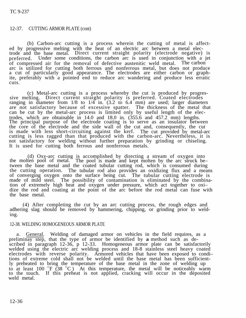
TC 9-237
12-37. CUTTING ARMOR PLATE (cont)
(b) Carbon-arc cutting is a process wherein the cutting of metal is affect-ed by progressive melting with the heat of an electric arc between a metal elec-trode and the base metal. Direct current straight polarity (electrode negative) ispreferred. Under some conditions, the carbon arc is used in conjunction with a jetof compressed air for the removal of defective austenitic weld metal. The carbonarc is utilized for cutting both ferrous and nonferrous metal, but does not producea cut of particularly good appearance. The electrodes are either carbon or graph-ite, preferably with a pointed end to reduce arc wandering and produce less erraticcuts.
(c) Metal-arc cutting is a process whereby the cut is produced by progres-sive melting. Direct current straight polarity is preferred. Coated electrodesranging in diameter from 1/8 to 1/4 in. (3.2 to 6.4 mm) are used; larger diametersare not satisfactory because of excessive spatter. The thickness of the metal thatcan be cut by the metal-arc process is limited only by useful length of the elec-trodes, which are obtainable in 14.0 and 18.0 in. (355.6 and 457.2 mm) lengths.The principal purpose of the electrode coating is to serve as an insulator betweenthe core of the electrode and the side wall of the cut and, consequently, the cutis made with less short-circuiting against the kerf. The cut provided by metal-arccutting is less ragged than that produced with the carbon-arc. Nevertheless, it isnot satisfactory for welding without further preparation by grinding or chiseling.It is used for cutting both ferrous and nonferrous metals.
(d) Oxy-arc cutting is accomplished by directing a stream of oxygen intothe molten pool of metal. The pool is made and kept molten by the arc struck be–tween the base metal and the coated tubular cutting rod, which is consumed duringthe cutting operation. The tubular rod also provides an oxidizing flux and a meansof converging oxygen onto the surface being cut. The tubular cutting electrode ismade of mild steel. The possibility of contamination is eliminated by the combina-tion of extremely high heat and oxygen under pressure, which act together to oxi–dize the rod and coating at the point of the arc before the rod metal can fuse withthe base metal.
(4) After completing the cut by an arc cutting process, the rough edges andadhering slag should be removed by hammering, chipping, or grinding prior to weld-ing.
12-38. WELDING HOMOGENEOUS ARMOR PLATE
a. General. Welding of damaged armor on vehicles in the field requires, as apreliminay step, that the type of armor be identified by a method such as de-scribed in paragraph 12-36, p 12-33. Homogeneous armor plate can be satisfactorilywelded using the electric arc welding process and 18-8 stainless steel heavy coatedelectrodes with reverse polarity. Armored vehicles that have been exposed to condi–tions of extreme cold shall not be welded until the base metal has been sufficient-ly preheated to bring the temperature of the base metal in the zone of welding upto at least 100 OF (38 OC ) At this temperature, the metal will be noticeably warmto the touch. If this preheat is not applied, cracking will occur in the depositedweld metal.
12-36
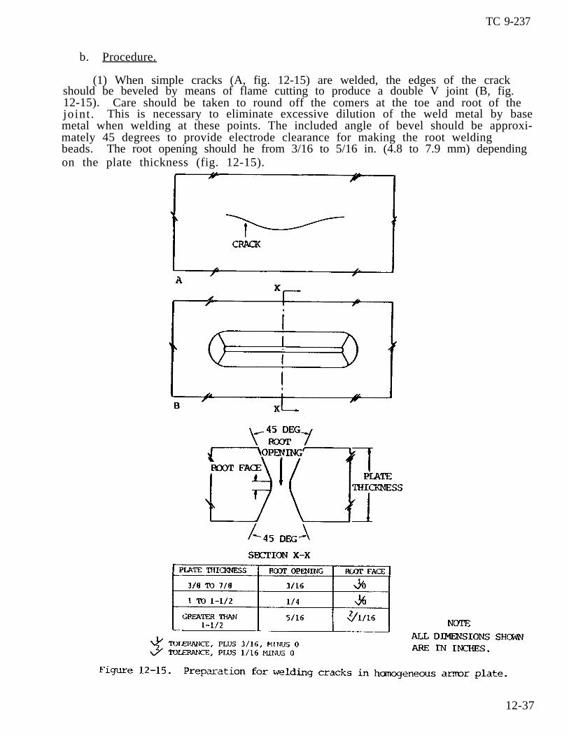
TC 9-237
b. Procedure.
(1) When simple cracks (A, fig. 12-15) are welded, the edges of the crackshould be beveled by means of flame cutting to produce a double V joint (B, fig.12-15). Care should be taken to round off the comers at the toe and root of thejoint . This is necessary to eliminate excessive dilution of the weld metal by basemetal when welding at these points. The included angle of bevel should be approxi-mately 45 degrees to provide electrode clearance for making the root weldingbeads. The root opening should he from 3/16 to 5/16 in. (4.8 to 7.9 mm) dependingon the plate thickness (fig. 12-15).
12-37
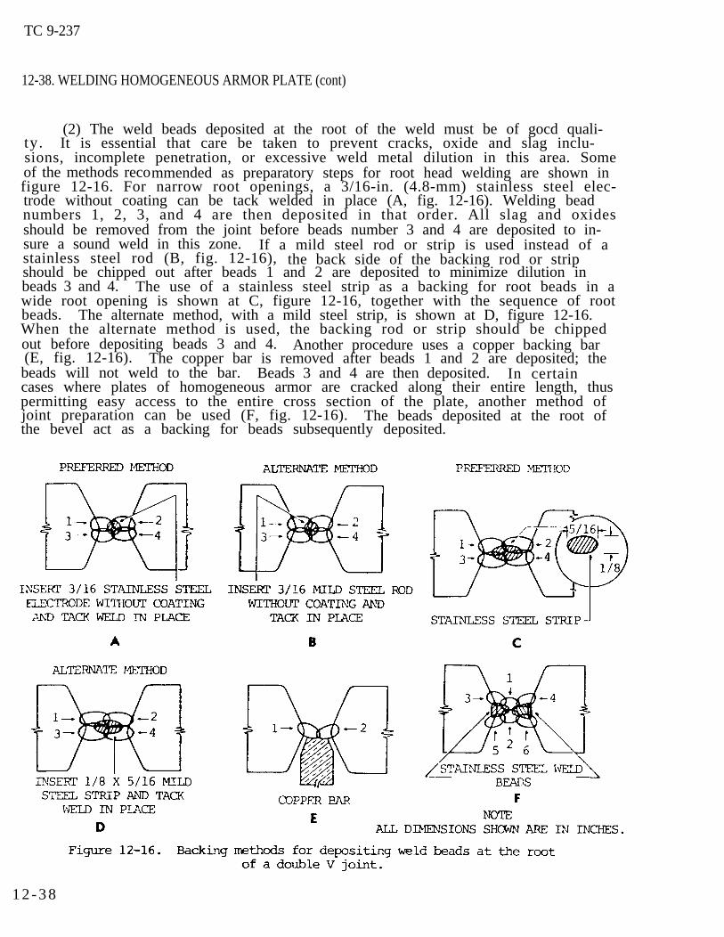
TC 9-237
12-38. WELDING HOMOGENEOUS ARMOR PLATE (cont)
(2) The weld beads deposited at the root of the weld must be of gocd quali-ty. It is essential that care be taken to prevent cracks, oxide and slag inclu-sions, incomplete penetration, or excessive weld metal dilution in this area. Someof the methods recommended as preparatory steps for root head welding are shown infigure 12-16. For narrow root openings, a 3/16-in. (4.8-mm) stainless steel elec-trode without coating can be tack welded in place (A, fig. 12-16). Welding beadnumbers 1, 2, 3, and 4 are then deposited in that order. All slag and oxidesshould be removed from the joint before beads number 3 and 4 are deposited to in-sure a sound weld in this zone. If a mild steel rod or strip is used instead of astainless steel rod (B, fig. 12-16), the back side of the backing rod or stripshould be chipped out after beads 1 and 2 are deposited to minimize dilution inbeads 3 and 4. The use of a stainless steel strip as a backing for root beads in awide root opening is shown at C, figure 12-16, together with the sequence of rootbeads. The alternate method, with a mild steel strip, is shown at D, figure 12-16.When the alternate method is used, the backing rod or strip should be chippedout before depositing beads 3 and 4. Another procedure uses a copper backing bar(E, fig. 12-16). The copper bar is removed after beads 1 and 2 are deposited; thebeads will not weld to the bar. Beads 3 and 4 are then deposited. In certaincases where plates of homogeneous armor are cracked along their entire length, thuspermitting easy access to the entire cross section of the plate, another method ofjoint preparation can be used (F, fig. 12-16). The beads deposited at the root ofthe bevel act as a backing for beads subsequently deposited.
1 2 - 3 8

TC 9-237
(3) A major factor to consider when welding cracks in armor that terminatewithin the plates is weld crater and fusion zone cracking, especially in the footbeads. An intermittent backstep and overlap procedure (C, fig. 12-17) is recommend-ed to overcome or avoid this hazard. It should be noted that all of the weldingsteps necessary to complete bead number 1 are completed before bead number 2 isstarted. By backstepping the passes, the craters at the end of each pass are locat-ed on previously deposited metal and are therefore less subject to cracking. Allcraters on subsequent passes that do not terminte on previously deposited metalshould be filled by the hesitation and drawback technique to avoid the formation ofstar cracks which are caused by the solidification of shallow deposits of moltenmetal.
12-39

TC 9-237
12-38. WELDING HOMOGENEOUS ARMOR PLATE (cont)
(4) Each pass in beads 1, 2, 3, and 4 (A and B, fig. 12–17, p 12-39) is limit–ed to l to 2 in. (25.4 to 50.8 mm) in length and should be peened while the weldmetal is still hot to help overcome the cooling stresses. No electrode weavingmotion should be used when the root beads are deposited, and the welding should beperformed preferably with a 5/32-in. (4.O-mm) electrode. Peening also tends toeliminate or minimize warpage in the section being welded. ArC blow should be con-trolled by properly adjusting the welding. Some of the more common defects encoun-tered when welding root beads on homogeneous armor plate and the proper remedialprocedures are shown in figure 12-18.
1 2 - 4 0
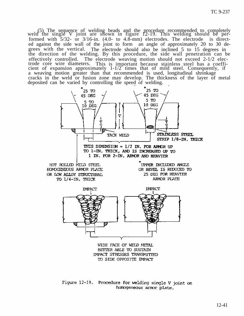
TC 9-237
(5) The sequence of welding beads and the procedure recommended to completelyweld the single V joint are shown in figure 12-19. This welding should be per-formed with 5/32- or 3/16-in. (4.0- to 4.8-mm) electrodes. The electrode is direct-ed against the side wall of the joint to form an angle of approximately 20 to 30 de-grees with the vertical. The electrode should also be inclined 5 to 15 degrees inthe direction of the welding. By this procedure, the side wall penetration can beeffectively controlled. The electrode weaving motion should not exceed 2-1/2 elec-trode core wire diameters. This is important because stainless steel has a coeffi-cient of expansion approximately 1-1/2 times that of mild steel. Consequently, ifa weaving motion greater than that recommended is used, longitudinal shrinkagecracks in the weld or fusion zone may develop. The thickness of the layer of metaldeposited can be varied by controlling the speed of welding.
12-41
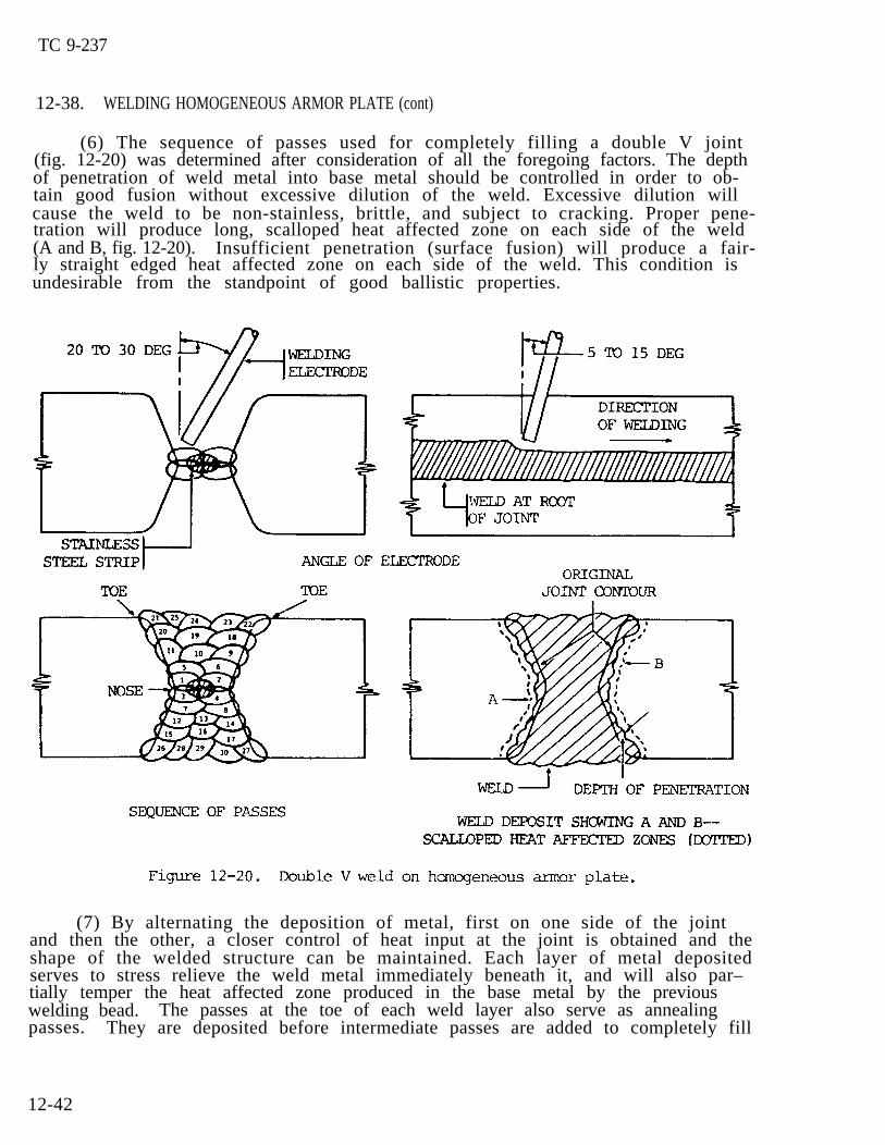
TC 9-237
12-38. WELDING HOMOGENEOUS ARMOR PLATE (cont)
(6) The sequence of passes used for completely filling a double V joint (fig. 12-20) was determined after consideration of all the foregoing factors. The depthof penetration of weld metal into base metal should be controlled in order to ob-tain good fusion without excessive dilution of the weld. Excessive dilution willcause the weld to be non-stainless, brittle, and subject to cracking. Proper pene-tration will produce long, scalloped heat affected zone on each side of the weld (A and B, fig. 12-20). Insufficient penetration (surface fusion) will produce a fair-ly straight edged heat affected zone on each side of the weld. This condition isundesirable from the standpoint of good ballistic properties.
(7) By alternating the deposition of metal, first on one side of the jointand then the other, a closer control of heat input at the joint is obtained and theshape of the welded structure can be maintained. Each layer of metal depositedserves to stress relieve the weld metal immediately beneath it, and will also par–tially temper the heat affected zone produced in the base metal by the previouswelding bead. The passes at the toe of each weld layer also serve as annealingpasses. They are deposited before intermediate passes are added to completely fill
12-42
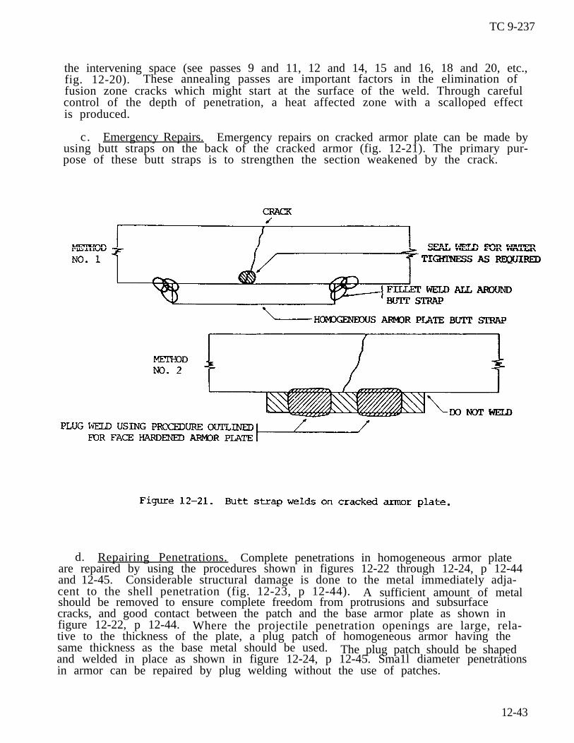
TC 9-237
the intervening space (see passes 9 and 11, 12 and 14, 15 and 16, 18 and 20, etc.,fig. 12-20). These annealing passes are important factors in the elimination offusion zone cracks which might start at the surface of the weld. Through carefulcontrol of the depth of penetration, a heat affected zone with a scalloped effectis produced.
c. Emergency Repairs. Emergency repairs on cracked armor plate can be made byusing butt straps on the back of the cracked armor (fig. 12-21). The primary pur-pose of these butt straps is to strengthen the section weakened by the crack.
d. Repairing Penetrations. Complete penetrations in homogeneous armor plateare repaired by using the procedures shown in figures 12-22 through 12-24, p 12-44and 12-45. Considerable structural damage is done to the metal immediately adja-cent to the shell penetration (fig. 12-23, p 12-44). A sufficient amount of metalshould be removed to ensure complete freedom from protrusions and subsurfacecracks, and good contact between the patch and the base armor plate as shown infigure 12-22, p 12-44. Where the projectile penetration openings are large, rela-tive to the thickness of the plate, a plug patch of homogeneous armor having thesame thickness as the base metal should be used. The plug patch should be shapedand welded in place as shown in figure 12-24, p 12-45. Sma1l diameter penetrationsin armor can be repaired by plug welding without the use of patches.
12-43
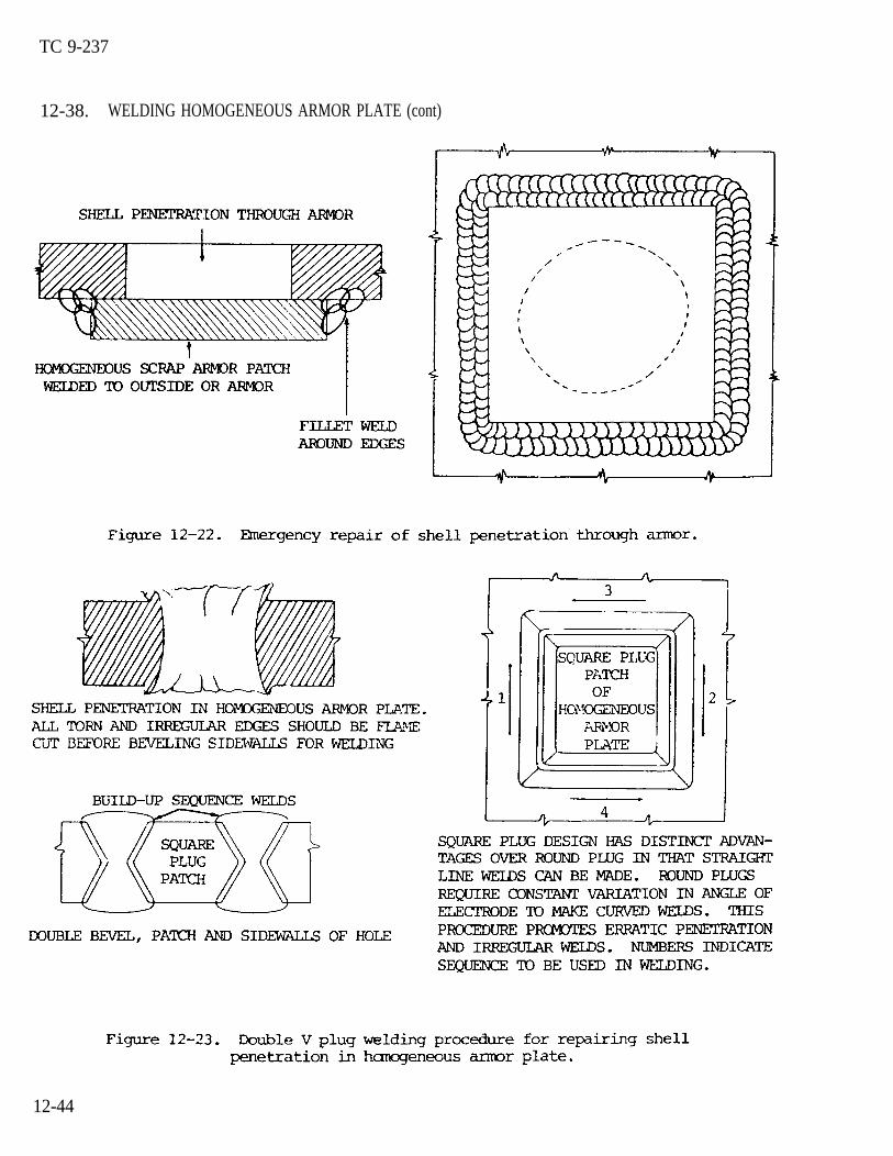
TC 9-237
12-38. WELDING HOMOGENEOUS ARMOR PLATE (cont)
12-44
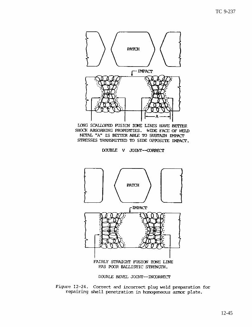
TC 9-237
12-45
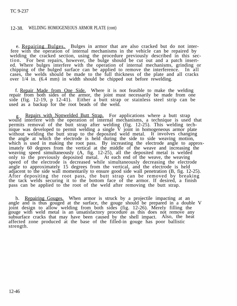
TC 9-237
12-38. WELDING HOMOGENEOUS ARMOR PLATE (cont)
e. Repairing Bulges. Bulges in armor that are also cracked but do not inter-fere with the operation of internal mechanisms in the vehicle can be repaired bywelding the cracked section, using the procedure previously described in this sec-t ion. For best repairs, however, the bulge should be cut out and a patch insert-ed. Where bulges interfere with the operation of internal mechanisms, grinding orchipping of the bulged surface can be applied to remove the interference. In allcases, the welds should be made to the full thickness of the plate and all cracksover 1/4 in. (6.4 mm) in width should be chipped out before rewelding.
f. Repair Made from One Side. Where it is not feasible to make the weldingrepair from both sides of the armor, the joint must necessarily be made from oneside (fig. 12-19, p 12-41). Either a butt strap or stainless steel strip can beused as a backup for the root beads of the weld.
g. Repairs with Nonwelded Butt Strap. For applications where a butt strapwould interfere with the operation of internal mechanisms, a technique is used thatpermits removal of the butt strap after welding (fig. 12-25). This welding tech-nique was developed to permit welding a single V joint in homogeneous armor platewithout welding the butt strap to the deposited weld metal. It involves changingthe angle at which the electrode is held during the side to side weaving motion,which is used in making the root pass. By increasting the electrode angle to approx-imately 60 degrees from the vertical at the middle of the weave and increasing theweaving speed simultaneously (A, fig. 12-25), all the deposited metal is weldedonly to the previously deposited metal. At each end of the weave, the weavingspeed of the electrode is decreased while simultaneously decreasing the electrodeangle to approximately 15 degrees from the vertical, and the electrode is heldadjacent to the side wall momentarily to ensure good side wall penetration (B, fig. 12-25).After depositing the root pass, the butt strap can be removed by breakingthe tack welds securing it to the bottom face of the armor. If desired, a finishpass can be applied to the root of the weld after removing the butt strap.
h. Repairing Gouges. When armor is struck by a projectile impacting at anangle and is thus gouged at the surface, the gouge should be prepared in a double Vjoint design to allow welding from both sides (fig. 12-26). Merely filling thegouge with weld metal is an unsatisfactory procedure as this does not remove anysubsurface cracks that may have been caused by the shell impact. Also, the heataffected zone produced at the base of the filled-in gouge has poor ballisticstrength.
12-46
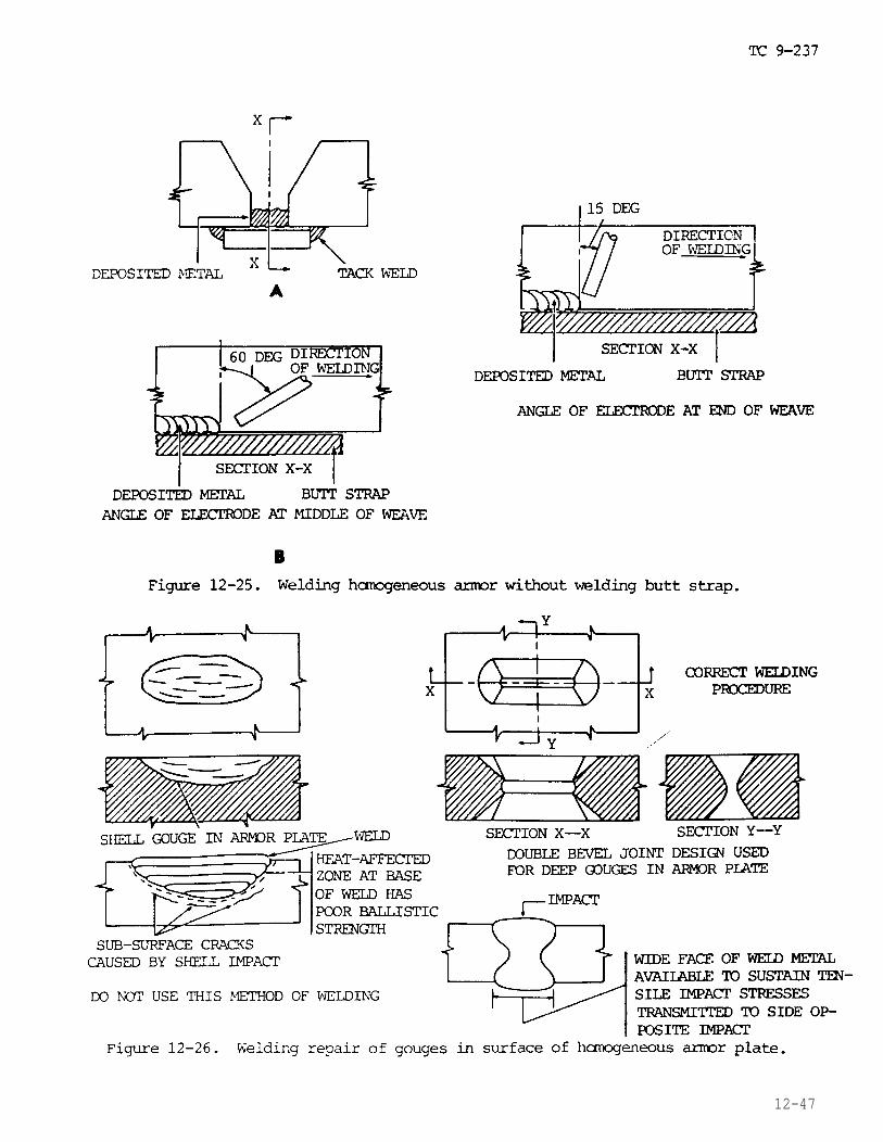
12-47
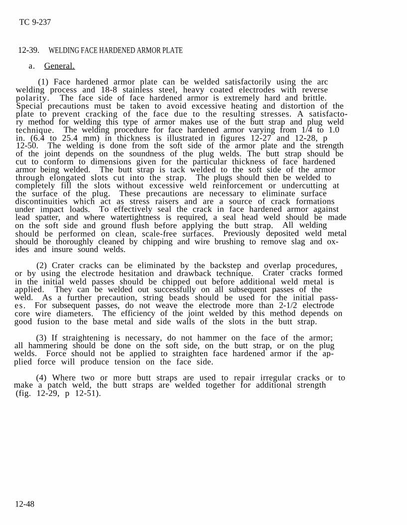
TC 9-237
12-39. WELDING FACE HARDENED ARMOR PLATE
a. General.
(1) Face hardened armor plate can be welded satisfactorily using the arcwelding process and 18-8 stainless steel, heavy coated electrodes with reversepolarity. The face side of face hardened armor is extremely hard and brittle.Special precautions must be taken to avoid excessive heating and distortion of theplate to prevent cracking of the face due to the resulting stresses. A satisfacto-ry method for welding this type of armor makes use of the butt strap and plug weldtechnique. The welding procedure for face hardened armor varying from 1/4 to 1.0in. (6.4 to 25.4 mm) in thickness is illustrated in figures 12-27 and 12-28, p12-50. The welding is done from the soft side of the armor plate and the strengthof the joint depends on the soundness of the plug welds. The butt strap should becut to conform to dimensions given for the particular thickness of face hardenedarmor being welded. The butt strap is tack welded to the soft side of the armorthrough elongated slots cut into the strap. The plugs should then be welded tocompletely fill the slots without excessive weld reinforcement or undercutting atthe surface of the plug. These precautions are necessary to eliminate surfacediscontinuities which act as stress raisers and are a source of crack formationsunder impact loads. To effectively seal the crack in face hardened armor againstlead spatter, and where watertightness is required, a seal head weld should be madeon the soft side and ground flush before applying the butt strap. All weldingshould be performed on clean, scale-free surfaces. Previously deposited weld metalshould be thoroughly cleaned by chipping and wire brushing to remove slag and ox-ides and insure sound welds.
(2) Crater cracks can be eliminated by the backstep and overlap procedures,or by using the electrode hesitation and drawback technique. Crater cracks formedin the initial weld passes should be chipped out before additional weld metal isapplied. They can be welded out successfully on all subsequent passes of theweld. As a further precaution, string beads should be used for the initial pass-es. For subsequent passes, do not weave the electrode more than 2-1/2 electrodecore wire diameters. The efficiency of the joint welded by this method depends ongood fusion to the base metal and side walls of the slots in the butt strap.
(3) If straightening is necessary, do not hammer on the face of the armor;all hammering should be done on the soft side, on the butt strap, or on the plugwelds. Force should not be applied to straighten face hardened armor if the ap-plied force will produce tension on the face side.
(4) Where two or more butt straps are used to repair irregular cracks or tomake a patch weld, the butt straps are welded together for additional strength(fig. 12-29, p 12-51).
12-48
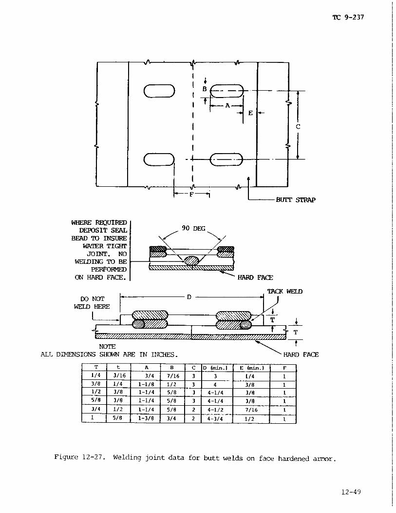
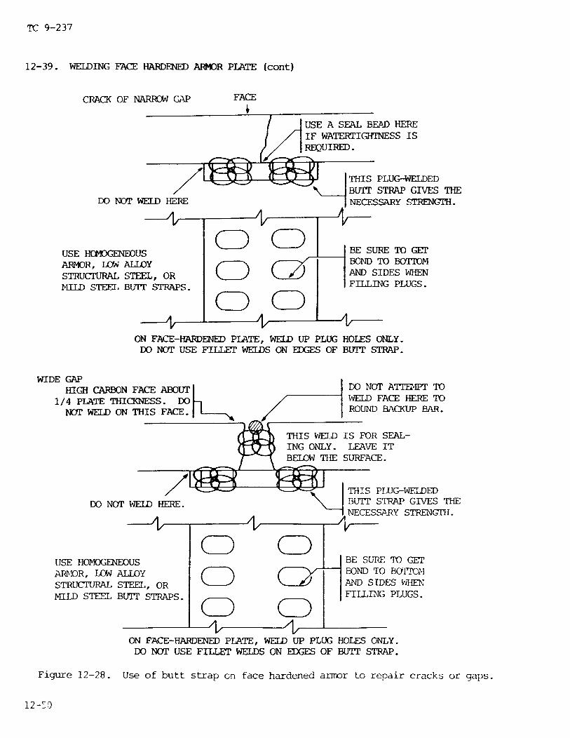

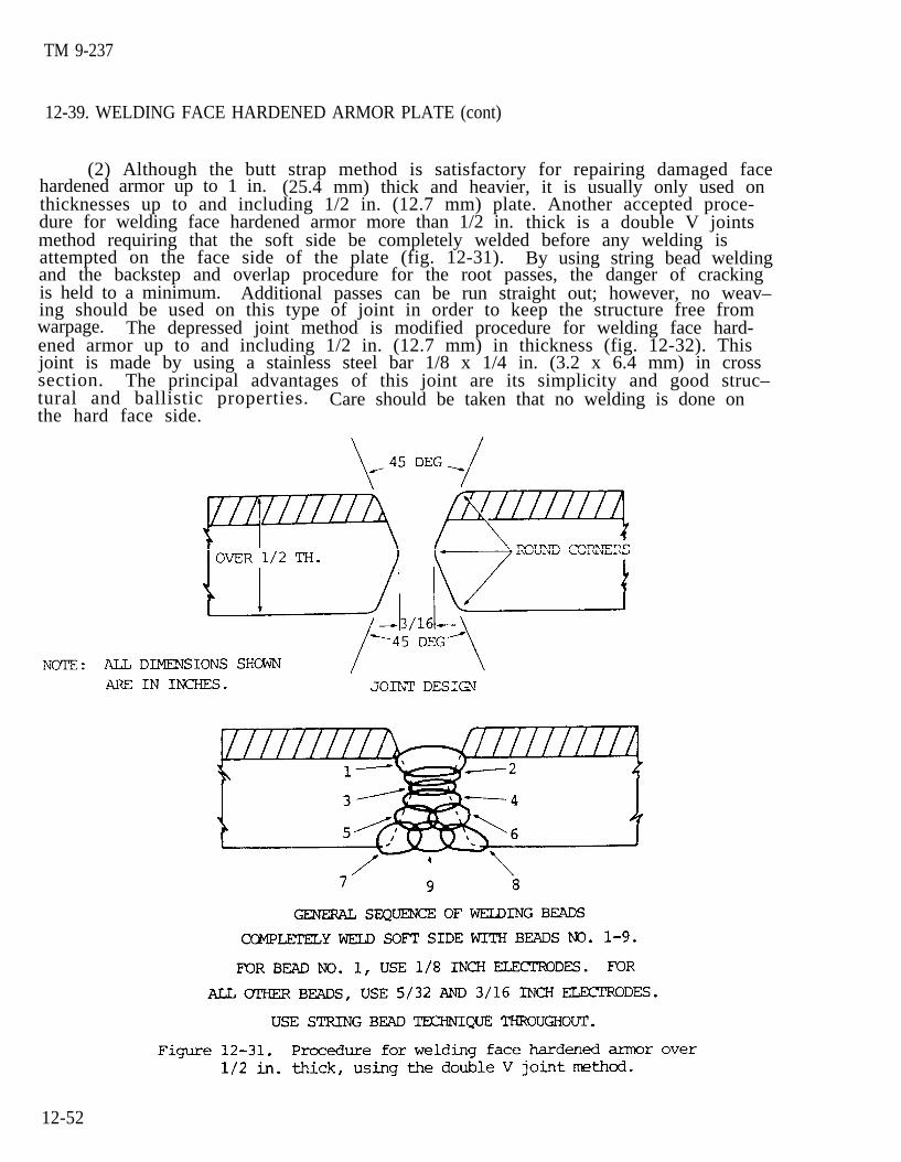
TM 9-237
12-39. WELDING FACE HARDENED ARMOR PLATE (cont)
(2) Although the butt strap method is satisfactory for repairing damaged facehardened armor up to 1 in. (25.4 mm) thick and heavier, it is usually only used onthicknesses up to and including 1/2 in. (12.7 mm) plate. Another accepted proce-dure for welding face hardened armor more than 1/2 in. thick is a double V jointsmethod requiring that the soft side be completely welded before any welding isattempted on the face side of the plate (fig. 12-31). By using string bead weldingand the backstep and overlap procedure for the root passes, the danger of crackingis held to a minimum. Additional passes can be run straight out; however, no weav–ing should be used on this type of joint in order to keep the structure free fromwarpage. The depressed joint method is modified procedure for welding face hard-ened armor up to and including 1/2 in. (12.7 mm) in thickness (fig. 12-32). Thisjoint is made by using a stainless steel bar 1/8 x 1/4 in. (3.2 x 6.4 mm) in crosssection. The principal advantages of this joint are its simplicity and good struc–tural and ballistic properties. Care should be taken that no welding is done onthe hard face side.
12-52
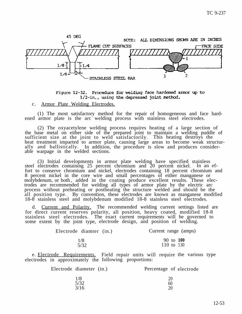
TC 9-237
c. Armor Plate Welding Electrodes.
(1) The most satisfactory method for the repair of homogeneous and face hard-ened armor plate is the arc welding process with stainless steel electrodes.
(2) The oxyacetylene welding process requires heating of a large section ofthe base metal on either side of the prepared joint to maintain a welding puddle ofsufficient size at the joint to weld satisfactorily. This heating destroys theheat treatment imparted to armor plate, causing large areas to become weak structur-ally and ballistically. In addition, the procedure is slow and produces consider-able warpage in the welded sections.
(3) Initial developments in armor plate welding have specified stainlesssteel electrodes containing 25 percent chromium and 20 percent nickel. In an ef-fort to conserve chromium and nickel, electrodes containing 18 percent chromium and8 percent nickel in the core wire and small percentages of either manganese ormolybdenum, or both , added in the coating produce excellent results. These elec-trodes are recommended for welding all types of armor plate by the electric arcprocess without preheating or postheating the structure welded and should be theall position type. By convention, these electrodes are known as manganese modified18-8 stainless steel and molybdenum modified 18-8 stainless steel electrodes.
d. Current and Polarity. The recommended welding current settings listed arefor direct current reserves polarity, all position, heavy coated, modified 18-8stainless steel electrodes. The exact current requirements will be governed tosome extent by the joint type, electrode design, and position of welding.
1/85/32
e. Electrode Requirements.electrodes in approximately the
Electrode diamter (in.) Current range (amps)
90 to110 to
Field repair units will requirefollowing proportions:
Electrode diameter (in.) Percentage of
1/8 205/32 603/16 20
100130
the various type
electrode
12-53
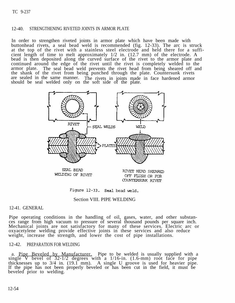
TC 9-237
12-40. STRENGTHENING RIVETED JOINTS IN ARMOR PLATE
In order to strengthen riveted joints in armor plate which have been made withbuttonhead rivets, a seal bead weld is recommended (fig. 12-33). The arc is struckat the top of the rivet with a stainless steel electrode and held there for a suffi-cient length of time to melt approximately 1/2 in. (12.7 mm) of the electrode. Abead is then deposited along the curved surface of the rivet to the armor plate andcontinued around the edge of the rivet until the rivet is completely welded to thearmor plate. The seal bead weld prevents the rivet head from being sheared off andthe shank of the rivet from being punched through the plate. Countersunk rivetsare sealed in the same manner. The rivets in joints made in face hardened armorshould be seal welded only on the soft side of the plate.
Section VIII. PIPE WELDING
12-41. GENERAL
Pipe operating conditions in the handling of oil, gases, water, and other substan-ces range from high vacuum to pressure of several thousand pounds per square inch.Mechanical joints are not satisfactory for many of these services. Electric arc oroxyacetylene welding provide effective joints in these services and also reduceweight, increase the strength, and lower the cost of pipe installations.
12-42. PREPARATION FOR WELDING
a. Pipe Beveled by Manufacturer. Pipe to be welded is usually supplied with asingle V bevel of 32-1/2 degrees with a 1/16-in. (1.6-mm) root face for pipethicknesses up to 3/4 in. (19.1 mm). A single U groove is used for heavier pipe.If the pipe has not been properly beveled or has been cut in the field, it must be beveled prior to welding.
12-54
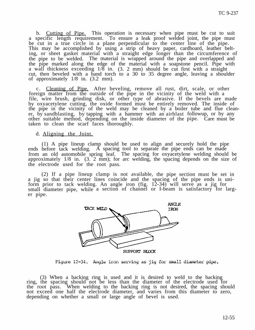
TC 9-237
b. Cutting of Pipe. This operation is necessary when pipe must be cut to suita specific length requirement. To ensure a leak proof welded joint, the pipe mustbe cut in a true circle in a plane perpendicular to the center line of the pipe.This may be accomplished by using a strip of heavy paper, cardboard, leather belt-ing, or sheet gasket material with a straight edge longer than the circumference ofthe pipe to be welded. The material is wrapped around the pipe and overlapped andthe pipe marked along the edge of the material with a soapstone pencil. Pipe witha wall thickness exceeding 1/8 in. (3. 2 mm) should be cut first with a straightcut, then beveled with a hand torch to a 30 to 35 degree angle, leaving a shoulderof approximately 1/8 in. (3.2 mm).
c. Cleaning of Pipe. After beveling, remove all rust, dirt, scale, or otherforeign matter from the outside of the pipe in the vicinity of the weld with afile, wire brush, grinding disk, or other type of abrasive. If the bevels are madeby oxyacetylene cutting, the oxide formed must be entirely removed. The inside ofthe pipe in the vicinity of the weld may be cleaned by a boiler tube and flue clean-er, by- sandblasting, by- tapping with a hammer with an- airblastother suitable method, depending on the inside diameter of thetaken to clean the scarf faces thoroughly.
followup, or by anypipe. Care must be
d. Aligning the Joint.
(1) A pipe lineup clamp should be used to align and securely hold the pipeends before tack welding. A spacing tool to separate the pipe ends can be madefrom an old automobile spring leaf. The spacing for oxyacetylene welding should beapproximately 1/8 in. (3. 2 mm); for arc welding, the spacing depends on the size ofthe electrode used for the root pass.
(2) If a pipe lineup clamp is not available, the pipe section must be set ina jig so that their center lines coincide and the spacing of the pipe ends is uni-form prior to tack welding. An angle iron (fig. 12-34) will serve as a jig forsmall diameter pipe, whileer pipe.
a section of channel or I-beam is satisfactory for larg-
(3) When a backing ring is used and it is desired to weld to the backingring, the spacing should not be less than the diameter of the electrode used forthe root pass. When welding to the backing ring is not desired, the spacing shouldnot exceed one half the electrode diameter, and varies from this diameter to zero,depending on whether a small or large angle of bevel is used.
12-55

TC 9-237
12-42. PREPARATION FOR WELDING (cont)
e . Backing Rings and Tack Welding.
(1) The purpose of a backing ring is to make possible the complete penetra-tion of the weld metal to the inside of the pipe without excessive burning through,to prevent spattered metal and slag from entering the pipe at the joint, and toprevent the formation of projections and other irregular shaped formations of metalon the inside of the joint. Backing rings also aid materially in securing properalignment of the pipe ends and, when used, are inserted during assembly of the joint . Backing rings are not used when the pipe service requires a completelysmooth inner pipe surface of uniform internal diameter.
(2) There are several types of backing rings: the plain flat strip rolled tofit the inside of the joint; the forged or pressed type (with or without projec-tions); the circumferential rib which spaces the pipe ends the proper distanceapart; and the machined ring. All shapes may be of the continuous or split ringtypes. Several backing rings are shown in figure 12-35.
12-56
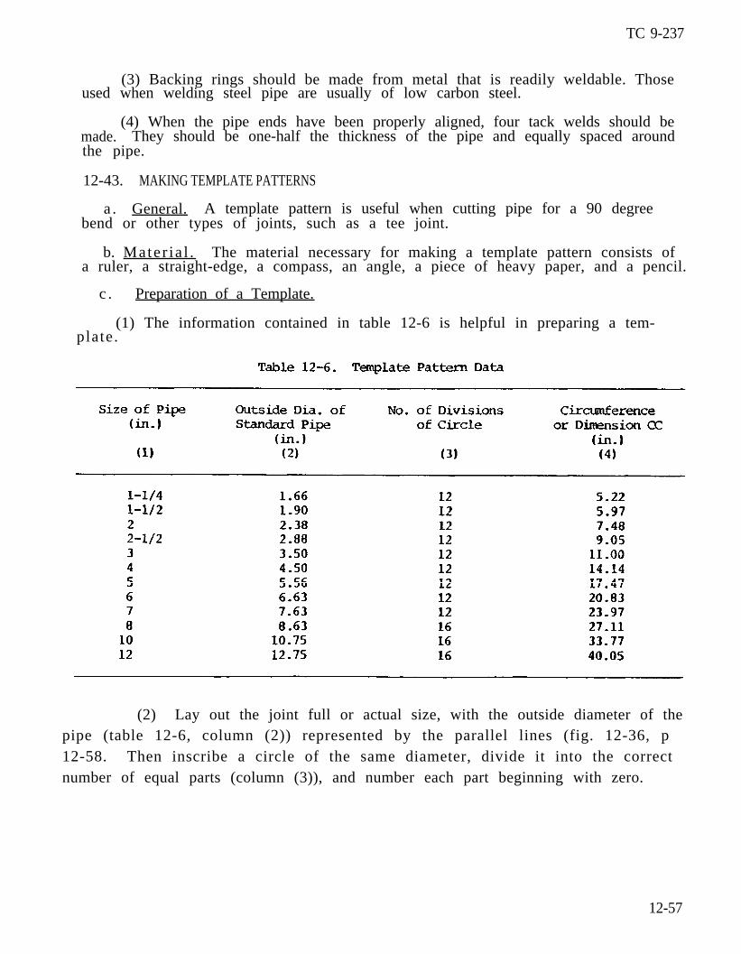
TC 9-237
(3) Backing rings should be made from metal that is readily weldable. Thoseused when welding steel pipe are usually of low carbon steel.
(4) When the pipe ends have been properly aligned, four tack welds should bemade. They should be one-half the thickness of the pipe and equally spaced aroundthe pipe.
12-43. MAKING TEMPLATE PATTERNS
a . General. A template pattern is useful when cutting pipe for a 90 degreebend or other types of joints, such as a tee joint.
b. Mater ia l . The material necessary for making a template pattern consists ofa ruler, a straight-edge, a compass, an angle, a piece of heavy paper, and a pencil.
c . Preparation of a Template.
(1) The information contained in table 12-6 is helpful in preparing a tem-plate.
(2) Lay out the joint full or actual size, with the outside diameter of the pipe (table 12-6, column (2)) represented by the parallel lines (fig. 12-36, p 12-58. Then inscribe a circle of the same diameter, divide it into the correct number of equal parts (column (3)), and number each part beginning with zero.
12-57
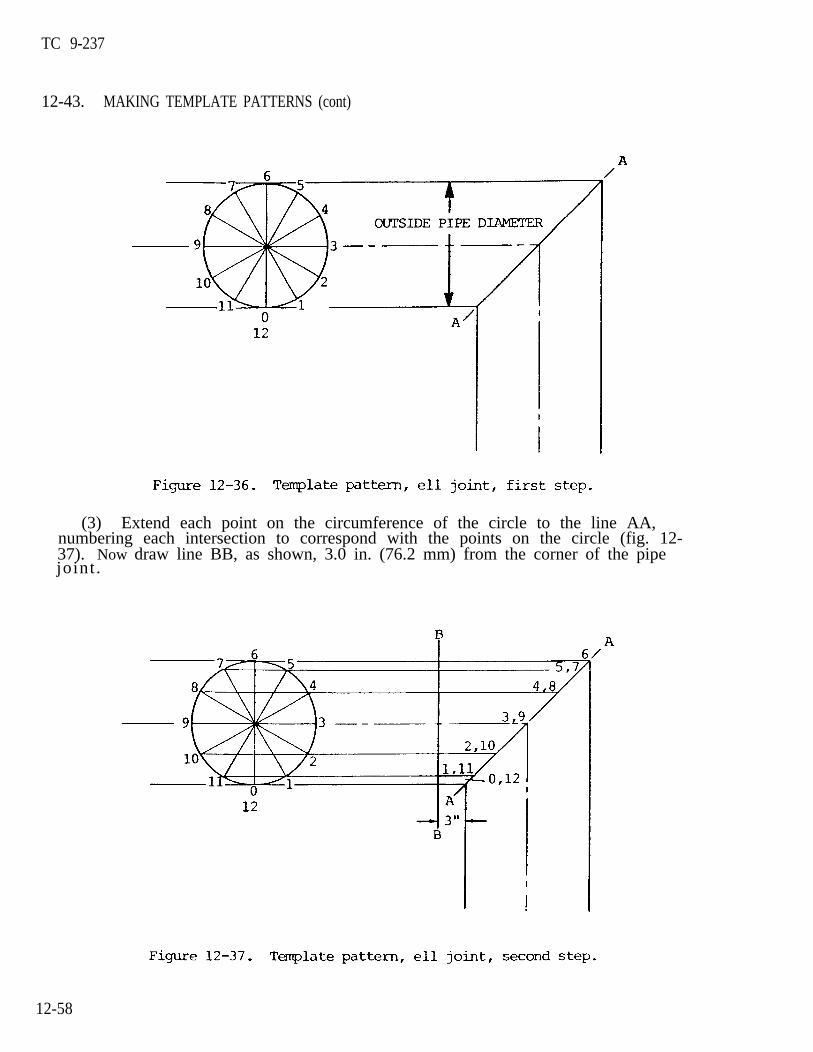
TC 9-237
12-43. MAKING TEMPLATE PATTERNS (cont)
(3) Extend each point on the circumference of the circle to the line AA,numbering each intersection to correspond with the points on the circle (fig. 12-37). Now draw line BB, as shown, 3.0 in. (76.2 mm) from the corner of the pipejoint .
12-58
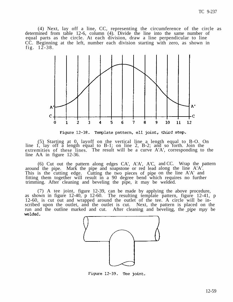
TC 9-237
(4) Next, lay off a line, CC, representing the circumference of the circle asdetermined from table 12-6, column (4). Divide the line into the same number ofequal parts as the circle. At each division, draw a line perpendicular to lineCC. Beginning at the left, number each division starting with zero, as shown inf ig . 12-38 .
(5) Starting at 0, layoff on the vertical line a length equal to B-O. Online 1, lay off a length equal to B-1; on line 2, B-2; and so forth. Join theextremities of these lines. The result will be a curve A'A', corresponding to theline AA in figure 12-36.
(6) Cut out the pattern along edges CA', A'A', A'C,around the pipe. Mark the pipe and soapstone or red leadThis is the cutting edge. Cutting the two pieces of pipe
and CC. Wrap the patternalong the line A'A'.on the line A'A' and
fitting them together will result in a 90 degree bend which requires no furthertrimming. After cleaning and beveling the pipe, it may be welded.
(7) A tee joint, figure 12-39, can be made by applying the above procedure,as shown in figure 12-40, p 12-60. The resulting template pattern, figure 12-41, p12-60, is cut out and wrapped around the outlet of the tee. A circle will be in-scribed upon the outlet, and the outlet is cut. Next, the pattern is placed on therun and the outline marked and cut. After cleaning and beveling, the pipe may be
12-59
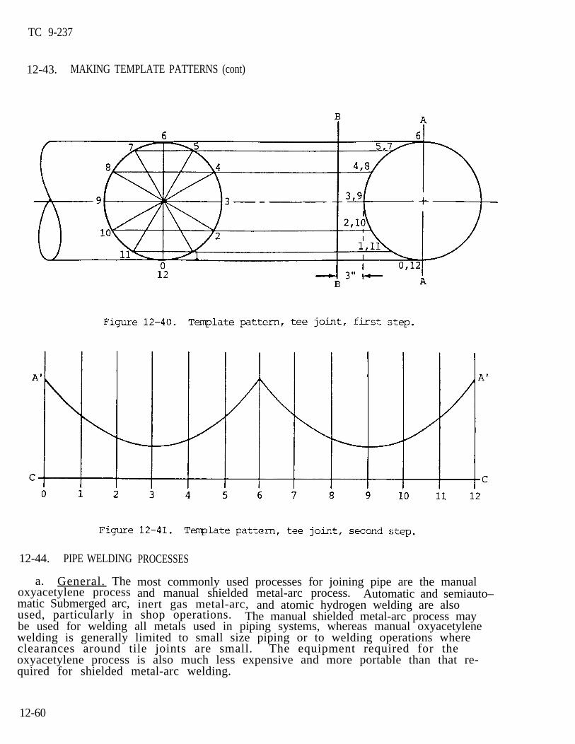
TC 9-237
12-43. MAKING TEMPLATE PATTERNS (cont)
12-44. PIPE WELDING PROCESSES
most commonly used processes for joining pipe are the manualand manual shielded metal-arc process. Automatic and semiauto–inert gas metal-arc, and atomic hydrogen welding are also
a. General. Theoxyacetylene processmatic Submerged arc,used, particularly in shop operations. The manual shielded metal-arc process maybe used for welding all metals used in piping systems, whereas manual oxyacetylenewelding is generally limited to small size piping or to welding operations whereclearances around tile joints are small. The equipment required for the oxyacetylene process is also much less expensive and more portable than that re-quired for shielded metal-arc welding.
12-60

TC 9-237
b. Shielded Metal-Arc Process.
(1) The shielded metal-arc process can be used for welding pipe materialssuch as aluminum, magnesium, and high chromium-nickel alloys that are difficult toweld by other processes. In shielded metal-arc welding, the number of passes re-quired for welding ferrous metal piping varies with the pipe thickness, the weldingposition, the size of the electrode, and the welding current used.
(2) The number of passes required for welding low alloy and low carbon steelpipe depends on the thickness of the pipe, the welding position, the size of theelectrode, and the current used but, in general, is approximately one pass for each1/8 in. (3.2 mm) of pipe thickness. When welding in the horizontal or rolled posi-tion, the number of layers is usually increased 25 to 30 percent. Smaller elec-trodes are used to lessen the heat concentration and to ensure complete grain re-finement of the weld metal.
(3) The electrodes used vary from 1/8 to 5/32 in. (3.2 to 4.0 mm) diameterfor the first pass, 5/32 in. (4.0 mm) diameter for the intermediate passes, and upto 3/16 in. (4.8 mm) for the top passes and reinforcement.
c. Manual Oxyacetylene Welding. The number of passes required for pipe weldingwith the oxyacetylene flame depends on the thickness of the pipe, the position ofthe pipe, and the size of the welding rod used. The thickness of the depositedlayer is somewhat more than that deposited by the shielded metal-arc process.
d. Direction of Welding.
(1) In manual shielded metal-arc welding, as much welding as possible is donein the flat or downhand position using suitable power driven equipment for rotatingthe pipe at a speed consistent with the speed of welding. When the pipe is in afixed horizontal position, the weld is usually made from the bottom upward. Withthin or medium thickness pipe, the welding is done downward. More metal is deposit-ed when welding upward. Complete grain refinement is easier to achieve, and weld–ing downward requires a much higher degree of manual skill.
(2) When the pipe is in a fixed vertical position, it is customary to depositthe filler metal in a series of overlapping string beads, using 1/8 in. (3.2 mm)maximum electrodes, and allowing 25 to 30 beads per square inch of weld area.
(3) When welding by the oxyacetylene process, the directions of welding asdescribed above will, in general, apply. Backhand welding is used when weldingdownward, and forehand welding is used when welding upward.
12-45. PIPE WELDING PROCEDURES
a. Horizontal Pipe Rolled Weld.
(1) Align the joint and tack weld or hold in position with steel bridgeclamps with the pipe mounted on suitable rollers (fig. 12-42, p 12–62). S ta r twelding at point C, figure 12-42, p 12-62, progressing upward to point B. When Bis reached, rotate the pipe clockwise until the stopping point of the weld is atpoint C and again weld upward to point B. When the pipe is being rotated, thetorch should be held between B and C and the pipe rotated past it.
12-61
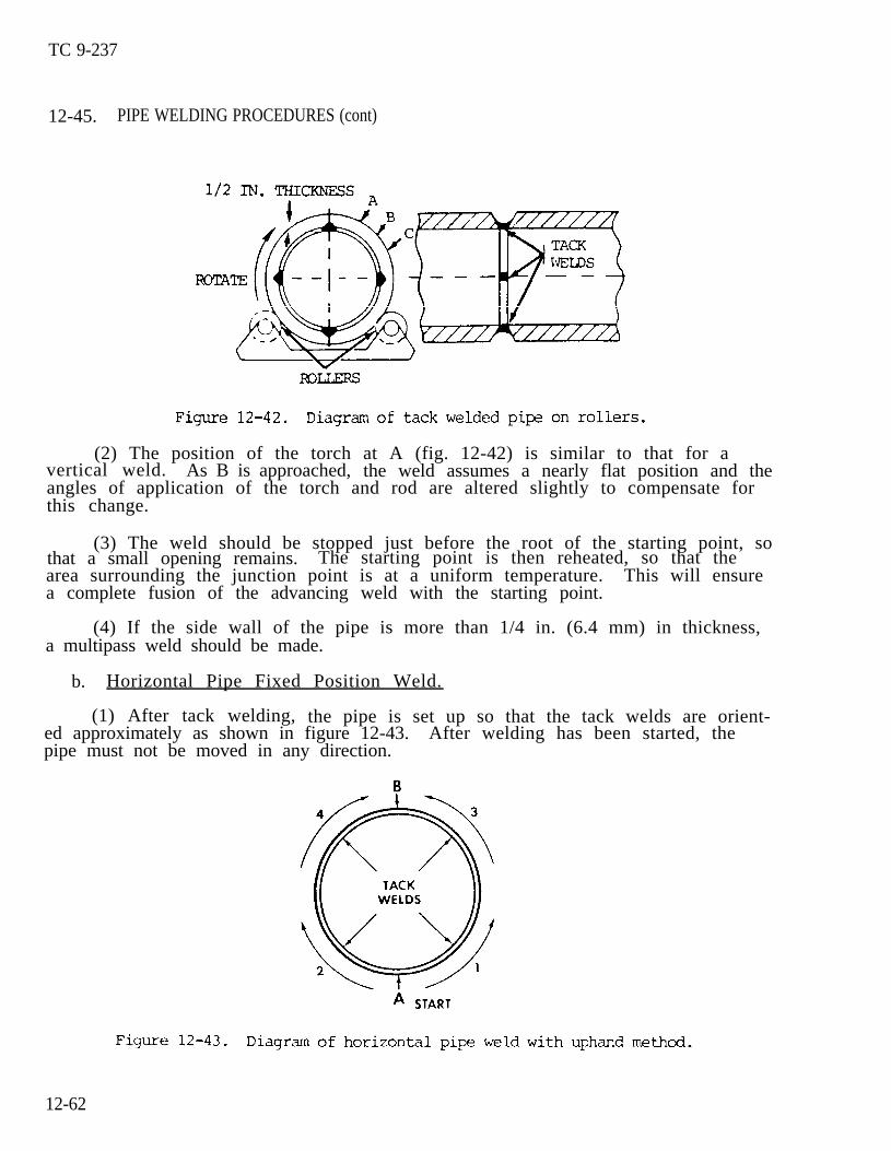
TC 9-237
12-45. PIPE WELDING PROCEDURES (cont)
(2) The position of the torch at A (fig. 12-42) is similar to that for avertical weld. As B is approached, the weld assumes a nearly flat position and theangles of application of the torch and rod are altered slightly to compensate forthis change.
(3) The weld should be stopped just before the root of the starting point, sothat a small opening remains. The starting point is then reheated, so that thearea surrounding the junction point is at a uniform temperature. This will ensurea complete fusion of the advancing weld with the starting point.
(4) If the side wall of the pipe is more than 1/4 in. (6.4 mm) in thickness,a multipass weld should be made.
b. Horizontal Pipe Fixed Position Weld.
(1) After tack welding, the pipe is set up so that the tack welds are orient-ed approximately as shown in figure 12-43. After welding has been started, thepipe must not be moved in any direction.
12-62

TC 9-237
(2) When welding in the horizontal fixed position, the pipe is welded in foursteps.
Starting at the bottom of 6 o’clock position, weld upward to the 3 Step 1. o’clock position.
Step 2. Starting back at the bottom, weld upward to the 9 o'clock position.
Step 3. S ta r t ing back a t the 3 o’c lock pos i t ion , weld to the top .
Step 4. Starting back at the 9 o’clock position, weld upward to the top.
(3) When welding downward, the weld is made in two stages. Start at the top
overlapping the bead.
(fig. 12-44) and work down one side (1, fig. 12-44) to the bottom, then return tOthe top and work down the other side (2, fig. 12-44) to join with the previous weldat the bottom. The welding downward method is particularly effective with arcwelding, since the higher temperature of the electric arc makes the use of greaterwelding speeds possible. With arc welding, the speed is approximately three timesthat of the upward welding method.
(4) Welding by the backhand method is used for joints in low carbon or lowalloy steel piping that can be rolled or are in horizontal position. One pass isused for wall thicknesses not exceeding 3/8 in. (9.5 mm), two passes for wallthicknesses 3/8 to 5/8 in. (9.5 to 15.9 mm), three passes for wall thicknesses 5/8to 7/8 in. (15.9 to 22.2 mm), and four for wall thicknesses 7/8 to 1-1/8 in. (22.2to 28.6 mm).
Vertical Pipe Fixed Position Weld. Pipe in this position, where the jointis horizontal, is most frequently welded by the backhand method (fig. 12-45, p12-64). The weld is started at the tack and carried continuously around the pipe.
c.
12-63

TC 9-237
12-45. PIPE WELDING PROCEDURES (cont)
d. M u l t i p a s s A r c W e l d i n g
(1) Root beads. If a lineup clamp is used, the root bead (A, fig. 12-46) isstarted at the bottom of the groove while the clamp is in position. When no back–ing ring is used, take care to build up a slight bead on the inside of the pipe.If a backing ring is used, the root bead must be carefully fused to it. As muchroot bead as the bars of the lineup clamp willclamp is removed. Complete the bead after the
permit should be applied before theclamp is removed.
12-64
TC 9-237
(2) Filler beads. Ensure the filler beads (B, fig. 12-46) are fused into theroot bead in order to remove any undercut caused by the deposition of the rootbead. One or more filler beads around the pipe will usually be required.
(3) Finish beads. The finish beads (C, fig. 12-46) are applied over thefiller beads to complete the joint. Usually, this is a weave bead about 5/8 in.(15.9 mm) wide and approximately 1/16 in. (1.6 mm) above the outside surface of thepipe when complete. The finish weld is shown at D.
Section IX. WELDING CAST IRON, CAST STEEL, CARBON STEEL, AND FORGINGS
12-46. CAST IRON, CAST STEEL, CARBON STEEL, AND FORGINGS
a. In general, parts composed of these metals can be repaired by the same proce-dure as that used for their assembly. They can also be repaired by brazing orsoldering if the joining equipment originally used is not available or suitable forthe purpose. For instance, cast iron and cast steel may be repaired by gas weld-ing, arc welding, or by brazing. Parts or sections made of carbon steel originallyassembled by spot, projection, or flash welding may be repaired by gas or arc weld-ing. The same is true of forgings.
b. Gray cast iron has a low ductility and therefore will not expand or stretchto any considerable extent before breaking or cracking. Because of this character-istic, preheating is necessary when cast iron is welded by the oxyacetylene pro-cess. It can, however, be welded with the metal-arc process without preheating ifthe welding heat is carefully controlled. Large castings with complicated sec-tions, such as motor blocks, can be welded without dismantling or preheating.Special electrodes designed for this purpose are usually desirable.
c. Generally, the weldability of cast steel is comparable to that of wroughtsteels. Cast steels are usually welded in order to join one cast item to anotheror to a wrought steel item, and to repair defects in damaged castings. Theweldability of steels is primarily a function of composition and heat treatment.Therefore, the procedures and precautions required for welding wrought steel alsoapply to cast steels of similar composition, heat treatment, and strength. Weldingof cast steels can sometimes be simplified by first considering the load in thearea being welded and the actual strength needed in the weld. Castings are oftencomplex; a specific analysis may be required for only part of the entire struc-ture. When welding a section of steel casting that does not require the fullstrength of the casting, lower-strength weld rods or wires can sometimes be used,or the part being welded to the casting can be of lower strength and leaner analy-sis than the cast steel part. Under such conditions, the deposited weld metalusually has to match only the strength of the lower-strength member. With heat-treatable electrodes, the welding sometimes can be done before final heat-treating.After being subjected to an austenitizing treatment (heating above the upper criti-cal temperature), weld deposits with carbon contents less than 0.12 percent usuallyhave lower mechanical properties than they have in the as welded or stress-relievedcondition.
d. Carbon steels are divided into three groups: low, medium, and high.
(1) Low carbon steels include those with a carbon content up to 0.30 per-cent. These low carbon steels do not harden appreciably when welded and thereforedo not require preheating or postheating except in special cases, such as whenheavy sections are to be welded.
12-65
TC 9-237
12-46. CAST IRON, CAST STEEL, CARBON STEEL, AND FORGINGS (cont)
(2) Medium carbon steels include those that contain from 0.30 to 0.55 percentcarbon. These steels are usually preheated to between 300 and 500 0F (149 and 2600C) before welding. Electrodes of the low carbon, heavy coated, straight or re-verse polarity type, similar to those used for metal arc welding of low carbonsteels, are satisfactory for steels in this group. The preheating temperature willvary depending on the thickness of the material and its carbon content. Afterwelding, the entire joint should be heated to between 1000 and 1200 0F (538 and 6490C) and slow cooled to relieve stresses in the base metal adjacent to the weld.
(3) High carbon steels include those that have a carbon content exceeding0.55 percent. Because of the high carbon content and the heat treatment usuallygiven to these steels, their basic properties are impaired by arc welding. Preheat-ing 500 to 800 0F (260 to 427 0C) before welding and stress relieving by heatingfrom 1200 to 1450 0F (649 to 788 0C) with slow cooling should be used to avoidhardness and brittleness in the fusion zone. Either mild steel or stainless steelelectrodes can be used with these steels.
e. Parts that were originally forge welded may be repaired by gas or arc weld-ing.
f. High hardness alloy steels are a variety of alloy steels that have beendeveloped to obtain high strength, high hardness, corrosion resistance, and otherspecial properties. Most of these steels depend on a special heat treatment pro–cess in order to develop the desired characteristic in the finished state. Many ofthese steels can be welded with a heavy coated electrode of the shielded arc typewhose composition is similar to that of the base metal. Low carbon electrodes canalso be used with some steels and stainless steel electrodes where preheating isnot practicable or is undesirable. Heat treated steels should be preheated, ifpossible, in order to minimize the formation of hard zones or layers in the basemetal adjacent to the weld. The molten metal should not be overheated, and forthis reason, the welding heat should be controlled by depositing the weld metal innarrow string beads. In many cases, the procedure outlined for medium carbonsteels and high carbon steels, including the principles of surface fusion, can beused in the welding of alloy steels.
g. High yield strength, low alloy structural steels are special steels that aretempered to obtain extreme toughness and durability. The special alloys and gener-al makeup of these steels require special treatment to obtain satisfactoryweldments.
12-47. PROCEDURES
a. Gray Cast Iron.
(1) Edge preparation. The edges of the joint should be chipped out or groundto form a 60 degree angle or bevel. The V should extend to approximately 1/8 in.(3.2 mm) from the bottom of the crack. A small hole should be drilled at each endof the crack to prevent it from spreading. All grease, dirt, and other foreignsubstances should be removed by washing with a suitable cleaning material.
12-66
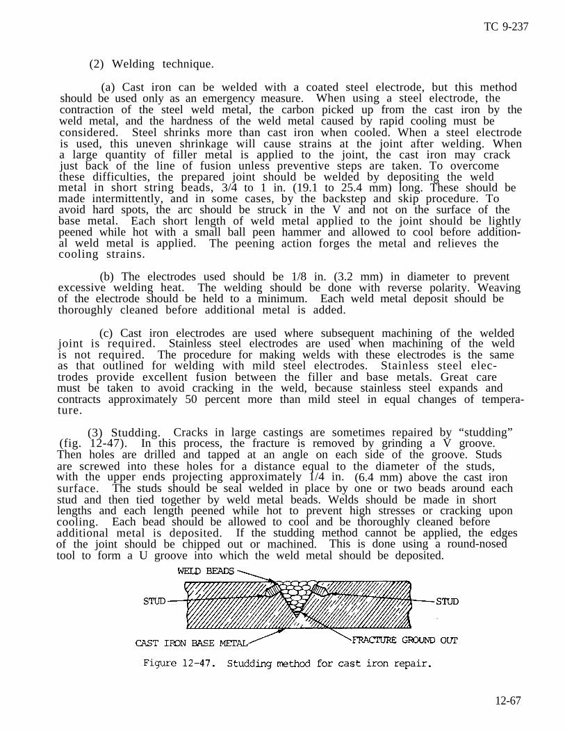
TC 9-237
(2) Welding technique.
(a) Cast iron can be welded with a coated steel electrode, but this methodshould be used only as an emergency measure. When using a steel electrode, thecontraction of the steel weld metal, the carbon picked up from the cast iron by theweld metal, and the hardness of the weld metal caused by rapid cooling must beconsidered. Steel shrinks more than cast iron when cooled. When a steel electrodeis used, this uneven shrinkage will cause strains at the joint after welding. Whena large quantity of filler metal is applied to the joint, the cast iron may crackjust back of the line of fusion unless preventive steps are taken. To overcomethese difficulties, the prepared joint should be welded by depositing the weldmetal in short string beads, 3/4 to 1 in. (19.1 to 25.4 mm) long. These should bemade intermittently, and in some cases, by the backstep and skip procedure. Toavoid hard spots, the arc should be struck in the V and not on the surface of thebase metal. Each short length of weld metal applied to the joint should be lightlypeened while hot with a small ball peen hammer and allowed to cool before addition-al weld metal is applied. The peening action forges the metal and relieves thecooling strains.
(b) The electrodes used should be 1/8 in. (3.2 mm) in diameter to preventexcessive welding heat. The welding should be done with reverse polarity. Weavingof the electrode should be held to a minimum. Each weld metal deposit should bethoroughly cleaned before additional metal is added.
(c) Cast iron electrodes are used where subsequent machining of the weldedjoint is required. Stainless steel electrodes are used when machining of the weldis not required. The procedure for making welds with these electrodes is the sameas that outlined for welding with mild steel electrodes. Stainless steel elec-trodes provide excellent fusion between the filler and base metals. Great caremust be taken to avoid cracking in the weld, because stainless steel expands andcontracts approximately 50 percent more than mild steel in equal changes of tempera-ture.
(3) Studding. Cracks in large castings are sometimes repaired by “studding”(fig. 12-47). In this process, the fracture is removed by grinding a V groove.Then holes are drilled and tapped at an angle on each side of the groove. Studsare screwed into these holes for a distance equal to the diameter of the studs,with the upper ends projecting approximately 1/4 in. (6.4 mm) above the cast ironsurface. The studs should be seal welded in place by one or two beads around eachstud and then tied together by weld metal beads. Welds should be made in shortlengths and each length peened while hot to prevent high stresses or cracking uponcooling. Each bead should be allowed to cool and be thoroughly cleaned beforeadditional metal is deposited. If the studding method cannot be applied, the edgesof the joint should be chipped out or machined. This is done using a round-nosedtool to form a U groove into which the weld metal should be deposited.
12-67

TC 9-237
12-47. PROCEDURES (cont)
(4) Metal-arc brazing of cast iron. Cast iron can be brazed with heavy coat-ed, reverse polarity bronze electrodes. The joints made by this method should beprepared in a manner similar to that used for oxyacetylene brazing of cast iron.The strength of the joint depends on the quality of the bond between the fillermetal and the cast iron base metal.
(5) Carbon-arc welding of cast iron. Iron castings may be welded with acarbon arc, a cast iron rod, and a cast iron welding flux. The joint should bepreheated by moving the carbon electrodes along the surface, thereby preventing toorapid cooling after welding. The molten puddle of metal can be worked with thecarbon electrode to remove any slag or oxides that are formed to the surface. Weldsmade with the carbon arc cool more slowly and are not as hard as those made withthe metal arc and a cast iron electrode. The welds are machinable.
b. Cast Steels.
(1) Joint designs for cast steel weldments are similar to those used forwrought steel.
(2) The choice of electrode filler metal is based on the type of cast steelbeing used, the strength needs of the joint, and the post-weld heat treatment.When welding carbon or low-alloy cast steels, the electrodes recommended for compa-rable wrought steel plate should be used. When cast austenitic stainless steelsare jointed to either cast or wrought ferritic materials, the proper filler metaldepends on the service conditions.
c. Carbon Steels.
(1) Low carbon steels.
(a) Metal-arc welding. In metal-arc welding, the bare, thin coated, orheavy coated shielded arc types of electrodes may be used. These electrodes are oflow carbon type (O.10 to 0.14 percent). Low carbon sheet or plate materials thathave been exposed to low temperatures should be preheated slightly to room tempera-ture before welding. In welding sheet metal up to 1/8 in. (3.2 mm) in thickness,the plain square butt joint type of edge preparation may be used. When long seamsare to be welded on this material, the edges should be spaced to allow for shrink-age because the deposited metal tends to pull the plates together. This shrinkageis less severe in arc welding than in gas welding. Spacing of approximately 1/8in. (3.2 mm) per foot of seam will suffice. The backstep or skip welding techniqueshould be used for short seams that are fixed to prevent warpage or distortion andminimize residual stresses. Heavy plates should be beveled to provide an includedangle up to 60 degrees, depending on the thickness. The parts should be tack weld-ed in place at short intervals along the seam. The first or root bead should bemade with an electrode small enough in diameter to obtain good penetration andfusion at the base of the joint. A 1/8 or 5/32 in. (3.2 to 4.0 mm) electrode issuitable for this purpose. This first bead should be thoroughly cleaned by chip-ping and wire brushing before additional layers of weld metal are deposited. Theadditional passes of filler metal should be made with a 5/32 or 3/16 in. (4.0 to4.8 mm) electrode. For overhead welding, best results are obtained by using stringbeads throughout the weld. When welding heavy sections that have been beveled from
12-68
TC 9-237
both sides, the weave beads should be deposited alternately on one side and thenthe other. This will reduce the amount of distortion in the welded structure.Each bead should be cleaned thoroughly to remove all scale, oxides, and slag beforeadditional metal is deposited. The motion of the electrode should be controlled tomake the bead uniform in thickness and to prevent undercutting and overlap at theedges of the weld.
(b) Carbon-arc welding. Low carbon sheet and plate up to 3/4 in. (19.1 mm)in thickness can be satisfactorily welded by the carbon-arc welding process. Thearc is struck against the plate edges, which are prepared in a manner similar tothat required for metal-arc welding. A flux should be used on the joint and fillermetal added as in oxyacetylene welding. A gaseous shield should be provided aroundthe molten base and filler metal, by means of a flux coated welding rod. The weld-ing should be done without overheating the molten metal. If these precautions arenot taken, the weld metal will absorb an excessive amount of carbon from the elec-trode and oxygen and nitrogen from the air. This will cause brittleness in thewelded joint.
(2) Medium carbon steels. The plates should be prepared for welding in amanner similar to that used for low carbon steels. When welding with low carbonsteel electrodes, the welding heat should be carefully controlled to avoid overheat-ing of the weld metal and excessive penetration into the side walls of the joint.This control is accomplished by directing the electrode more toward the previouslydeposited filler metal adjacent to the side walls than toward the side walls direct-ly. By using this procedure, the weld metal is caused to wash up against the sideof the joint and fuse with it without deep or excessive penetration. High weldingheats will cause large areas of the base metal in the fusion zone adjacent to thewelds to become hard and brittle. The area of these hard zones in the base metalcan be kept to a minimum by making the weld with a series of small string or weavebeads, which will limit the heat input. Each bead or layer of weld metal willrefine the grain in the weld immediately beneath it. This will anneal and lessenthe hardness produced in the base metal by the previous bead. When possible, thefinished joint should be heat treated after welding. Stress relieving is normallyused when joining mild steel. High carbon alloys should be annealed. When weldingmedium carbon steels with stainless steel electrodes, the metal should be depositedin string beads. This will prevent cracking of the weld metal in the fusion zone.When depositing weld metal in the upper layers of welds made on heavy sections, theweaving motion of the electrode should under no circumstances exceed three elec-t ie d iameters . Each successive bead of weld should be chipped, brushed, andcleaned prior to the laying of another bead.
(3) High carbon steels. The welding heat should be adjusted to provide goodfusion at the side walls and root of the joint without excessive penetration.Control of the welding heat can be accomplished by depositing the weld metal insmall string beads. Excessive puddling of the metal should be avoided because thiswill cause carbon to be picked up from the base which, in turn, will make the weldmetal hard and brittle. Fusion between the filler metal and the side walls shouldbe confined to a narrow zone. Use the surface fusion procedure prescribed formedium carbon steels. The same procedure for edge preparation, cleaning of thewelds, and sequence of welding beads as prescribed for low and medium carbon steelsapplies to high carbon steels. Small high carbon steel parts are sometimes re-paired by building up worn surfaces. When this is done, the piece should be an-nealed or softened by heating to a red heat and cooling slowly. Then the pieceshould be welded or built up with medium carbon or high strength electrodes andheat treated after welding to restore its original properties.
12-69
TC 9-237
12-47. PROCEDURES (cont)
d. Forgings should be welded with the gas or arc processes in a manner similarto parts originally assembled by spot, projection, or flash welding.
e. High hardness alloy steels can be welded with heavy coated electrodes of theshielded arc type whose composition is similar to that of the base metal. Lowcarbon electrodes can also be used with some steels. Stainless steel electrodesare effective where preheating is not practical or is undesirable. Heat treatedsteels should be preheated, if possible, in order to minimize formation of hardzones or layers in the base metal adjacent to the weld. The molten metal shouldnot be overheated. For this reason, the welding heat should be controlled by depos-iting the weld metal in narrow string beads. In many cases, the procedure outlinedfor medium carbon steels and high carbon steels, including the principles of sur-face fusion, can be used in the welding of alloy steels.
f . Reliable welding of high yield strength, loW alloy structural steels can beperformed by using the following guidelines:
(1) Hydrogen is the number one enemy of sound welds in alloy steels. There-fore, use only low hydrogen (MIL-E-18038 or MIL-E-22200/1) electrodes to preventunderbead cracking. Underbead cracking is caused by hydrogen picked up in theelectrode coating, released into the arc and absorbed by the molten metal.
(2) If the electrodes are in an airtight container, immediately upon openingthe container place the electrodes in a ventilated holding oven set at 250 to 3000F (121 to 149 0C). In the event that the electrodes are not in an airtight con-tainer, put them in a ventilated baking oven and bake for 1 to 1-1/4 hours at 8000F (427 0C). Baked electrodes should, while still warm, be placed in the holdingoven until used. Electrodes must be kept dry to eliminate absorption of hydrogen.Testing for moisture should be in accordance with MIL-E-22200.
Moisture stabilizer NSN 3439-00-400-0090 is an ideal holding oven forfield use (MIL-M-45558).
(3) Electrodes are identified by classification numbers which are alwaysmarked on the electrode containers. For low hydrogen coatings the last two numbersof the classification should be 15, 16, or 18. Electrodes of 5/32 and 1/8 in. (4.0and 3.2 mm) in diameter are the most commonly used since they are more adaptable toall types of welding of this type steel.
(4) Wire electrodes for submerged arc and gas-shielded arc welding are notclassified according to strength. Welding wire and wire-flux combinations used forsteels to be stress relieved should contain no more than 0.05 percent vanadium.Weld metal with more than 0.05 percent vanadium may become brittle if stress re-lieved. when using either the submerged arc or gas metal-arc welding processes toweld high yield strength, loW alloy structural steels to lower strength steels, thewire-flux and wire-gas combination should be the same as that recommended for the
NOTE
lower strength steels.
(5) For welding plates under 1 in.(10 0C) is not required except to remove
12-70
(25.4 mm) thick,surface moisture
preheating above 50 0Ffrom the base metal.

(6)order tograph orweld.
(7)1, along
TC 9-237
It is important to avoid excessive heat concentration when welding inallow the weld area to cool rather quickly. Either the heat input mono-the heat input calculator can be used to determine the heat input into the
For satisfactory welds use good welding practices, as defined in sectionwith the following procedures:
(a) Use a straight stringer bead whenever possible.
(b) Restrict weave to partial weave pattern. Best results are obtained bya slight circular motion of the electrode with the weave area never exceeding twoelectrode diameters.
(c) Never use a full weave pattern.
(d) Skip weld as practical.
(e) Peening of the weld is sometimes recommended to relieve stresses whilecooling larger pieces.
(f) Fillet welds should be smooth and correctly contoured. Avoid toecracks and undercutting. Electrodes used for fillet welds should be lower strengththan those used for butt welding. Air hammer peening of fillet welds can help toprevent cracks , especially if the welds are to be stress relieved. A soft steelwire pedestal can help to absorb shrinkage forces. Butter welding in the toe areabefore actual fillet welding strengthens the area where a toe crack may start. Abead is laid in the toe area, then ground off prior to the actual fillet welding.This butted weld bead must be located so that the toe passes of the fillet will belaid directly over it during actual fillet welding. Because of the additionalmaterial involved in fillet welding, the cooling rate is increased and heat inputsmay be extended about 25 percent.
Section X. FORGE WELDING
12-48. GENERAL
a. General. This is a group ofheating in a forge or other furnace
welding processes in which a weld is made byand by applying pressure or blows.
b. Roll Welding. This is a process in which heat is obtained from a furnaceand rolls are used to apply pressure.
c . Die Welding. This is a process in which heat is obtained from a furnace anddies are used to apply pressure.
d. Hammer Welding. This is a process in which heat is obtained from a forge orfurnace and hammer blows are used to apply pressure.
e. Forge welding, as performed by the blacksmith, is by far the oldest processfor joining metal pieces of parts, but hand forge welding is no longer used exten-sively because of the development of oxyacetylene and electric arc welding. It is ,however, an effective process under some field conditions and therefore, equipmentand procedures required in hand forge welding are described briefly in this manual.
12-71
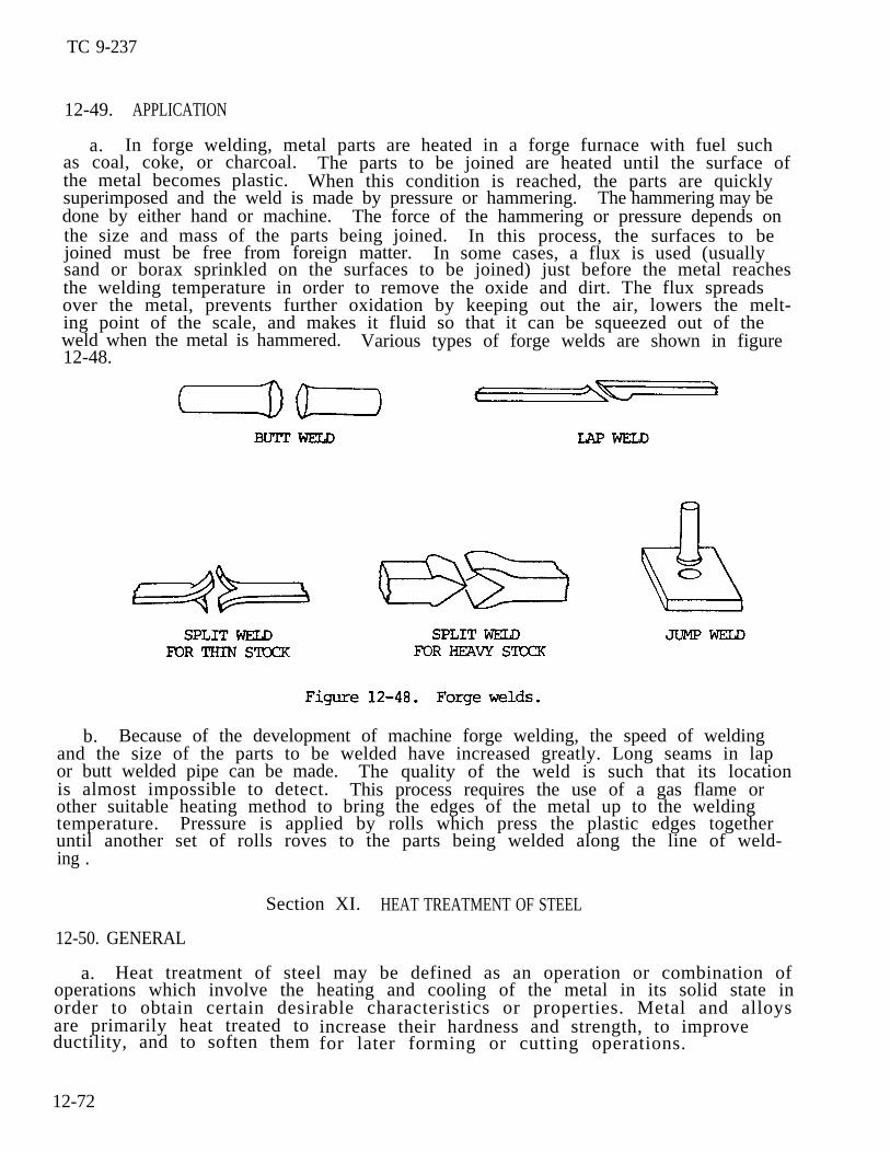
TC 9-237
12-49. APPLICATION
a. In forge welding, metal parts are heated in a forge furnace with fuel suchas coal, coke, or charcoal. The parts to be joined are heated until the surface ofthe metal becomes plastic. When this condition is reached, the parts are quicklysuperimposed and the weld is made by pressure or hammering. The hammering may bedone by either hand or machine. The force of the hammering or pressure depends onthe size and mass of the parts being joined. In this process, the surfaces to bejoined must be free from foreign matter. In some cases, a flux is used (usuallysand or borax sprinkled on the surfaces to be joined) just before the metal reachesthe welding temperature in order to remove the oxide and dirt. The flux spreadsover the metal, prevents further oxidation by keeping out the air, lowers the melt-ing point of the scale, and makes it fluid so that it can be squeezed out of theweld when the metal is hammered. Various types of forge welds are shown in figure12-48.
b. Because of the development of machine forge welding, the speed of weldingand the size of the parts to be welded have increased greatly. Long seams in lapor butt welded pipe can be made. The quality of the weld is such that its locationis almost impossible to detect. This process requires the use of a gas flame orother suitable heating method to bring the edges of the metal up to the weldingtemperature. Pressure is applied by rolls which press the plastic edges togetheruntil another set of rolls roves to the parts being welded along the line of weld-ing .
Section XI. HEAT TREATMENT OF STEEL
12-50. GENERAL
a. Heat treatment of steel may be defined as an operation or combination ofoperations which involve the heating and cooling of the metal in its solid state inorder to obtain certain desirable characteristics or properties. Metal and alloysare primarily heat treated toductility, and to soften them
12-72
increase their hardness and strength, to improve for later forming or cutting operations.
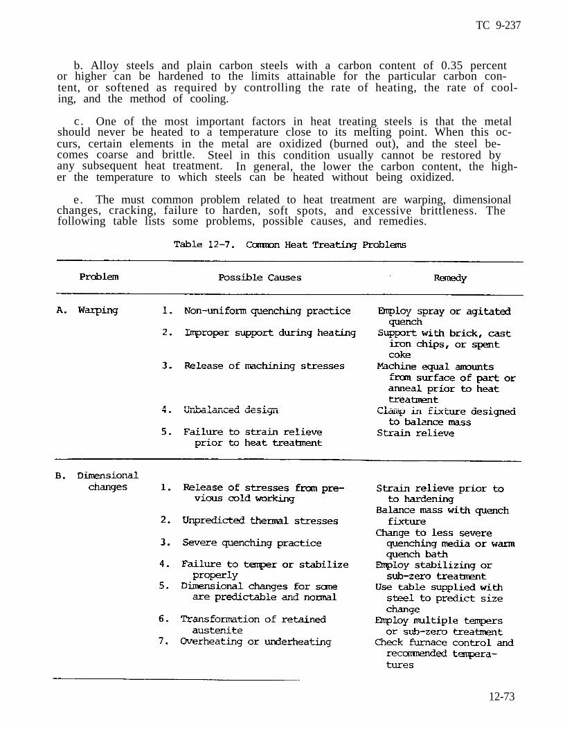
TC 9-237
b. Alloy steels and plain carbon steels with a carbon content of 0.35 percentor higher can be hardened to the limits attainable for the particular carbon con-tent, or softened as required by controlling the rate of heating, the rate of cool-ing, and the method of cooling.
c. One of the most important factors in heat treating steels is that the metalshould never be heated to a temperature close to its melting point. When this oc-curs, certain elements in the metal are oxidized (burned out), and the steel be-comes coarse and brittle. Steel in this condition usually cannot be restored byany subsequent heat treatment. In general, the lower the carbon content, the high-er the temperature to which steels can be heated without being oxidized.
e. The must common problem related to heat treatment are warping, dimensionalchanges, cracking, failure to harden, soft spots, and excessive brittleness. Thefollowing table lists some problems, possible causes, and remedies.
12-73
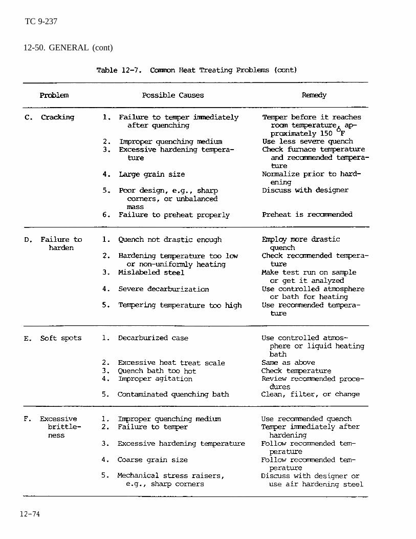
TC 9-237
12-50. GENERAL (cont)

TC 9-237
12-51. ANNEALNG
a. Annealing is a process involving the heating of a metal above the criticaltemperature and subsequent slow cooling. The purpose of such heating may be toremove stresses; induce softness; alter ductility, toughness, electrical, magnetic,or other physical properties; refine crystalline structure; remove gases; or pro-duce a definite microstructure.
b. Specific heat treatments which fall under the term annealing are:
(1) Full annealing. This is the heating of iron base alloys above the criti-cal temperature range, holding them above that range for a proper period of time,followed by cooling in a medium which will prolong the time of cooling.
(2) Process annealing. This is the heating of iron base alloys to a tempera-ture below or close to the lower limit of the critical temperature range, followedby cooling as desired.
(3) Normalizing. This is the heating of iron base alloys to approximately100 0F (38 0C) above the critical temperature range, followed by cooling to belowthat range in still air at ordinary temperature.
(4) Patenting. This is the heating of iron base alloys above the criticaltemperature range, followed by cooling below that range in air, molten lead, amolten mixture of nitrates, or nitrates maintained at a temperature usually between800 to 1050 0F (427 to 566 0C), depending on the carbon content of the steel andthe properties required of the finished product.
(5) Spheroidizing. This is any process of heating and cooling steel thatproduces a rounded or globular form of carbide. Methods of spheroidizing generallyused are:
(a) Prolonged heating at a temperature just below the lower critical temper-ature, usually followed by relatively slow cooling.
(b) In the case of small objects of high carbon steels, the spheroidizingresult is achieved more rapidly by prolonged heating to temperatures alternatelywithin and slightly below the critical temperature range.
(6) Tempering (also called drawing). This is reheating hardened steel tosome temperature below the lower critical temperature, followed by any desired rateof cooling.
(7) Malleablizing. This is an annealing operation performed on white castiron to partially or wholly transform the combined carbon to temper carbon, and insome cases, to wholly remove the carbon from the iron by decarburization.
(8) Graphitizing. This is a type of annealing of gray cast iron in whichsane or all of the combined carbon is transferred to free graphite carbon.
12-75
TC 9-237
12-52. HARDENING
a . Plain carbon steel is hardened by heating it above the critical temperatureand cooling it rapidly by plunging it into water, iced brine, or other liquid.When heating through the critical temperature range, iron undergoes a transforma-tion and changes from a form with low carbon solubility to one with high carbonsolubil i ty. Upon cooling, a reverse transformation occurs. Since these changesare progressive and require time for completion, they may be stopped if the coolingperiod is shortened.
b. If the cooling is very rapid, as in water quenching, the transformationtakes place much below the critical temperature range. The carbon is fixed tied in ahighly stressed, finely divided state, and the steel becomes hard, brittle, andmuch stronger than steel that is slowly cooled.
c. The presence of alloying elements alters the rate of transformation on cool-ing. Each alloy element shows individuality in its effect; therefore, alloy steelsare manufactured and heat treated to meet specific performance requirements.
12-53. TEMPERING
After a steel is hardened, it is too brittle for ordinary purposes. Some of thebadness should be removed and toughness induced. This process of reheating quenchhardened steel to a temperature below the transformation range and then, cooling itat any rate desired is called tempering. The metal must be heated uniformly to apredetermined temperature, depending on the toughness desired. As the temperingtemperature increases, toughness increases and hardness decreases. The temperingrange is usually between 370 and 750 0F (188 and 399 0C), as 1100 0F (593 0C).
12-54. SURFACE HARDENING
but sometimes is as high
a. General. A low carbon steel cannot be hardened to any great extent becauseof its low carbon content, yet the surface can be hardened by means of case harden-ing. The hardening is accomplished by increasing the carbon content of the surfaceonly.
b. Case Hardening. This process produces a hard surface resistant to wear butleaves a soft, tough core. It is accomplished as follows:
(1) Pack carburizing. The work is placed in a metal container and surroundedby a mixture of carburizing materials. The container is sealed and heated from 1to 16 hours at 1700 to 1800 0F (927 to 982 0C). The approximate penetration is7/1000 in. per hour. Carburizing is usually followed by quenching to produce ahardened case.
(2) Gas carburizing. The work is placed in a gas tight retort and heated to1700 (927 0C). Natural or manufactured gas is passed through the retort untilproper depth of hardening is obtained.
(3) Ni t r id ing . The work is placed in an atmosphere of ammonia gas at 950 0F(51O 0C) for a period of 10 to 90 hours. The maximum depth of 3/100 in. will bereached at 90 hours. The work is then removed and cooled slowly. Little warpagewill result because of the loW temperature. The case must then be ground so that it will be corrosion resistant.
12-76
WARNING Cyanide and cyanide fumes are dangerous piosons; therefore, this pro-c e s s r e q u i r e s e x p e r t s u p e r v i s i o n a n d a d e q u a t e v e n t i l a t i o n .
(4) Cyaniding. The work is preheated and immersed in a cyanide bath at1550 0F (843 0C). Time of immersion varies from a few minutes to 2 hours with aresulting penetration of 1/100 in. per hour. Parts should be tempered if toughnessis desired.
(5) Forge case hardening. This process, usually used in the field, is accom-plished by preheating work in a forge or with a torch up to 1650 0F (899 0C), thendipping the work in potassium cyanide or Kasenite and applying the flame. until thecompound melts. Repeat until required depth is attained and then quench.
c. Induction Hardening. This process is accomplished by the use of high fre-quency current with low voltage and a water spray to quench the work. It is usedonly on high carbon steels.
d. Flame Hardening. This process is accomplished by heating the surface to behardened with an oxyacetylene torch and quenching it in water. The steel must behigh in carbon.
12-55. USE OF CARBONIZING COMPOUND PASTE, NSN 6580-00-695-9268, AND ISOLATINGPASTE, NSN 6850-00-664-0355, FOR SURFACE HARDENING
a. General. The surface hardness of common steel is directly proportional toits carbon content. Low carbon steels may be given a hard exterior shell by in-creasing the amount of carbon in their surfaces. If the workpiece to be hardenedis packed in material of high carbon content and then brought to a relatively hightemperature, the carbon of the packing material transfers to the surface of theworkpiece and hardens it when it is quenched. The hard case created by quenchingis very brittle and may crack and chip easily. Toughness may be imparted to thisbrittle case by air cooling, reheating the workpiece to a somewhat lower tempera-ture than that used in the initial hardening, and then quickly quenching it. I t isoften desired to have only certain parts of a given workpiece hardened while retain-ing the basic toughness of the steel in the body of the workpiece; for example, thecutting edges of hand tools. This may be accomplished by packing the surfaces tobe hardened with the carbonizing material and the balance of the workpiece with anisolating material. Since the material used to pack the workpiece, either forhardening or for isolating, would dry and peel away in the furnace heat, it must besecured to the workpiece by some method of wrapping or shielding.
b. Workpiece of Preparation.
(1) Packing.
(a) Remove all rust, scale, and dirt from the workpiece to be hardened.
(b) Firmly press the nontoxicthe surfaces or edges to be hardened.(12.7 mm) thick.
carbonizing paste, NSN 6850-00-695-9268, onThe paste should be approximately 1/2 in.
12-77
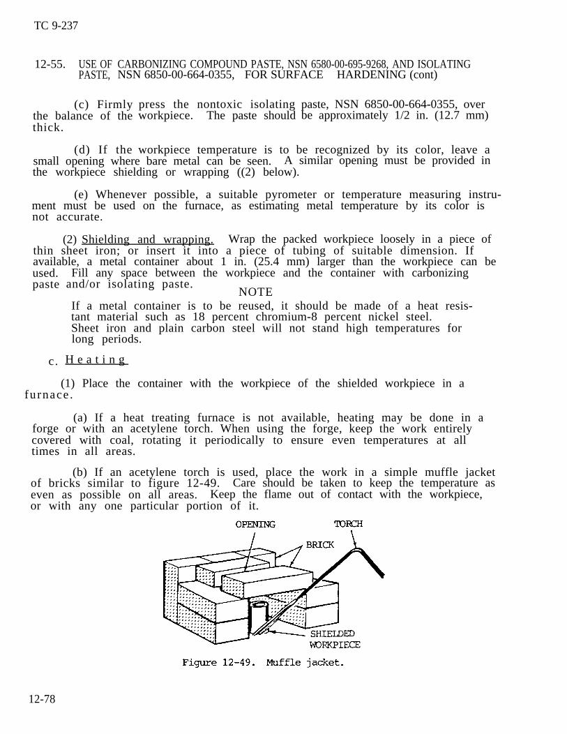
TC 9-237
12-55. USE OFPASTE,
CARBONIZING COMPOUND PASTE, NSN 6580-00-695-9268, AND ISOLATINGNSN 6850-00-664-0355, FOR SURFACE HARDENING (cont)
(c) Firmlythe balance of thethick.
(d) If the
press the nontoxic isolatingworkpiece. The paste should
paste, NSN 6850-00-664-0355, overbe approximately 1/2 in. (12.7 mm)
workpiece temperature is to be recognized by its color, leave asmall opening where bare metal can be seen. A similar opening must be provided inthe workpiece shielding or wrapping ((2) below).
(e) Whenever possible, a suitable pyrometer or temperature measuring instru-ment must be used on the furnace, as estimating metal temperature by its color isnot accurate.
(2) Shielding and wrapping. Wrap the packed workpiece loosely in a piece ofthin sheet iron; or insert it into a piece of tubing of suitable dimension. Ifavailable, a metal container about 1 in. (25.4 mm) larger than the workpiece can beused.paste
c.
Fill any space between the workpiece and the container with carbonizingand/or isolating paste.
If a metal container is to be reused, it should be made of a heat resis-tant material such as 18 percent chromium-8 percent nickel steel.Sheet iron and plain carbon steel will not stand high temperatures forlong periods.
NOTE
H e a t i n g
(1) Place the container with the workpiece of the shielded workpiece in afurnace .
(a) If a heat treating furnace is not available, heating may be done in aforge or with an acetylene torch. When using the forge, keep the work entirelycovered with coal, rotating it periodically to ensure even temperatures at alltimes in all areas.
(b) If an acetylene torch is used, place the work in a simple muffle jacketof bricks similar to figure 12-49. Care should be taken to keep the temperature aseven as possible on all areas. Keep the flame out of contact with the workpiece,or with any one particular portion of it.
12-78
TC 9-237
(2) The workpiece must be heated to 1700 0F (927 0C) (bright orange). Thetime needed to reach this temperature depends on the size of the workpiece and thefurnace.
heat for12-8.
(4)time.
(5)
(3) Note the time when the workpiece reaches 1700 0F (927 0C). Hold thisthe time required to give the desired
Remove the packed workpiece from the
depth of case
furnace after
hardening. See table
the required heating
The heating times listed in table 12-8 are general. They are intendedfor use with any low carbon steel.
12-56. QUENCHING AFTER CARBURIZING
After the workpiece has been removed from the furnace or forge, remove the shieldand packing and allow the workpiece to cool in the air until it reaches 1405 0F(763 0C). Then quench by plunging it in water or oil if required by the type ofsteel alloy. This procedure will not produce as good a grain structure as theprocedure outlined in paragraph 12-57 below.
12-57. DRAWING AND QUENCHING AFTER CARBURIZ ING
a . Normal Drawing and Quenching. For better structure in the finishedworkpiece, heat the workpiece as outlined in paragraph 12-55 (1) through (3), andremove it to cool to a black heat without removing the paste or the shield. Reheatthe still-packed workpiece in a furnace or forge to approximately 1450 0F (788 0C )(orange in furnace) for a few minutes. Then remove it from the heat, remove theshielding and packing, and quench by plunging in water or oil if required by thetype of steel alloy.
b. Drawing and Quenching SAE Steel. For the best grain structure in SAE steelworkplaces, follow the procedure outlined in a. above, except reheat the SAE steelto the temperature shown in table 12-9, p 12-80, before quenching. The workpieceis tempered after quenching. This method is generally used when the case hardeningpenetration is from 1/25 to 3/50 in. (1.0 to 1.5 mm).
12-79
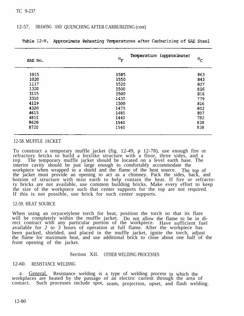
TC 9-237
12-57. DRAWING AND QUENCHING AFTER CARBURIZING (cont)
12-58. MUFFLE JACKET
To construct a temporary muffle jacket (fig. 12-49, p 12-78), use enough fire orrefractory bricks to build a boxlike structure with a floor, three sides, and atop. The temporary muffle jacket should be located on a level earth base. Theinterior cavity should be just large enough to comfortably accommodate theworkpiece when wrapped in a shield and the flame of the heat source. The top ofthe jacket must provide an opening to act as a chimney. Pack the sides, back, andbottom of structure with mist earth to help contain the heat. If fire or refracto-ry bricks are not available, use common building bricks. Make every effort to keepthe size of the workpiece such that center supports for the top are not required.If this is not possible, use brick for such center supports.
12-59. HEAT SOURCE
When using an oxyacetylene torch for heat, position the torch so that its flarewill be completely within the muffle jacket. Do not allow the flame to be in di-rect contract with any particular portion of the workpiece. Have sufficient fuelavailable for 2 to 3 hours of operation at full flame. After the workpiece hasbeen packed, shielded, and placed in the muffle jacket, ignite the torch, adjustthe flame for maximum heat, and use additional brick to close about one half of thefront opening of the jacket.
12-60.
a.
Section XII. OTHER WELDING PROCESSES
RESISTANCE WELDING
General. Resistance welding is a type of welding process in which theworkplaces are heated by the passage of an electric current through the area ofcontact. Such processes include spot, seam, projection, upset, and flash welding.
12-80

TC 9-237
b. Resistance Welding Process.
(1) Spot Welding. This is a resistance welding process wherein coalescenceis produced by the heat obtained from resistance to the flow of electric currentthrough the workpieces, which are held together under pressure by electrodes. Thesize and shape of the individually formal welds are limited primarily by the sizeand contour of the electrodes. Spot welding is particularly adaptable to thinsheet metal construction and has many applications in this type of work. The spotwelding principle is illustrated in figure 12-50.
(2) Roll spot welding. This is a resistance welding process wherein sepa-rate spot welds are made without retracting the electrodes. This is accomplishedby means of circular electrodes which are in continuous contact with the work.
(3) Seam welding. This is a resistance welding process wherein coalescenceis produced by the heat obtained from resistance to the flow of electric currentthrough the workplaces, which are held together under pressure by rotating circulare electrodes. The resulting weld is a series of overlapping spot welds made progres-sively along a joint. Lapped and flanged joints in cans, buckets, tanks, mufflers,e t c . , are commonly welded by this process.
(4) Projection welding. This is a process wherein coalescence is producedby the heat obtained from resistance to the flow of electric current through theworkpieces, which are held together under pressure by electrodes. The resultingwelds are localized at predetermined points by the design of the parts to be weld–ed. This localization is usually accomplished by projections, embossments, orintersections. This process is commonly used in the assembly of punched, formed,and stamped parts.
12-81
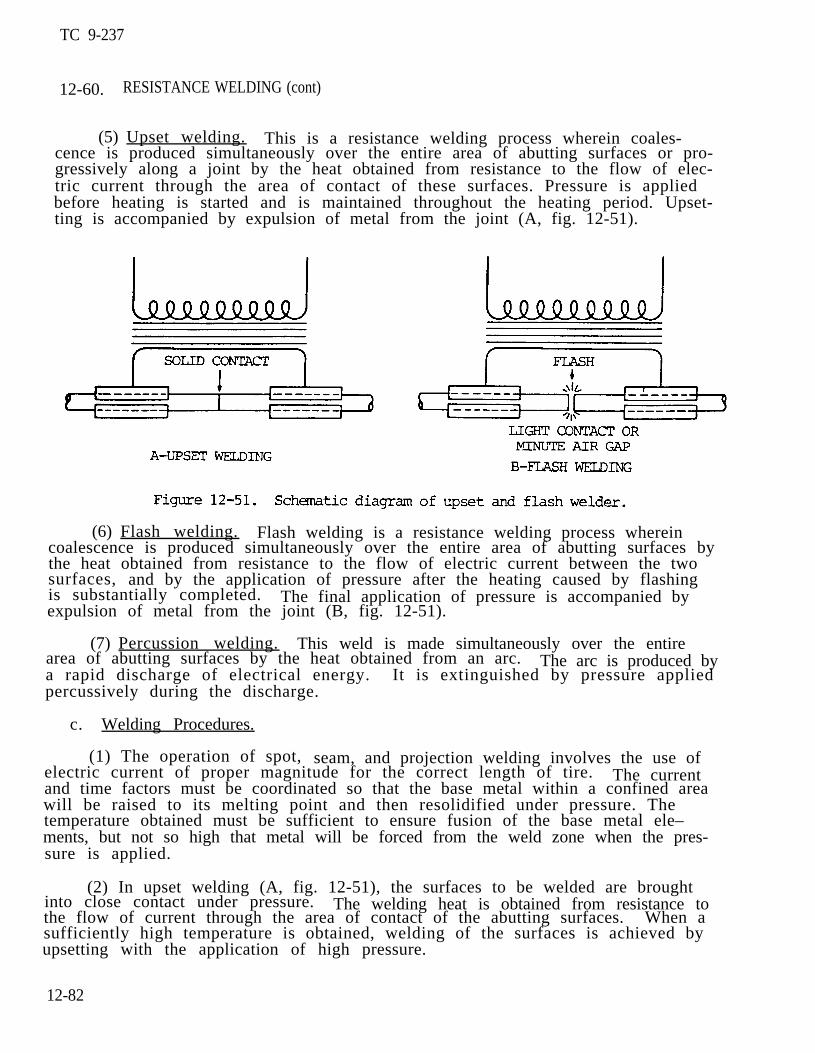
TC 9-237
12-60. RESISTANCE WELDING (cont)
(5) Upset welding. This is a resistance welding process wherein coales-cence is produced simultaneously over the entire area of abutting surfaces or pro-gressively along a joint by the heat obtained from resistance to the flow of elec-tric current through the area of contact of these surfaces. Pressure is appliedbefore heating is started and is maintained throughout the heating period. Upset-ting is accompanied by expulsion of metal from the joint (A, fig. 12-51).
(6) Flash welding. Flash welding is a resistance welding process whereincoalescence is produced simultaneously over the entire area of abutting surfaces bythe heat obtained from resistance to the flow of electric current between the twosurfaces, and by the application of pressure after the heating caused by flashingis substantially completed. The final application of pressure is accompanied byexpulsion of metal from the joint (B, fig. 12-51).
(7) Percussion welding. This weld is made simultaneously over the entirearea of abutting surfaces by the heat obtained from an arc. The arc is produced bya rapid discharge of electrical energy. It is extinguished by pressure appliedpercussively during the discharge.
c. Welding Procedures.
(1) The operation of spot, seam, and projection welding involves the use ofelectric current of proper magnitude for the correct length of tire. The currentand time factors must be coordinated so that the base metal within a confined areawill be raised to its melting point and then resolidified under pressure. Thetemperature obtained must be sufficient to ensure fusion of the base metal ele–ments, but not so high that metal will be forced from the weld zone when the pres-sure is applied.
(2) In upset welding (A, fig. 12-51), the surfaces to be welded are broughtinto close contact under pressure. The welding heat is obtained from resistance tothe flow of current through the area of contact of the abutting surfaces. When asufficiently high temperature is obtained, welding of the surfaces is achieved byupsetting with the application of high pressure.
12-82
TC 9-237
(3) In flash welding (B, fig. 12-51), the fusing of the parts is accomplishedin three steps. The surfaces to be joined are brought together under light pres-sure, then separated slightly to allow arcing to occur. This small arc brings themetals to their melting points at the separated ends and, as a final operation, themolten surfaces are forced together under heavy pressure. As they meet, the moltenmetal and slag are thrown out and a clean fusion is obtained.
12-61. SPOT WELDING MAGNESIUM
a. General. Magnesium can be joined by spot, seam, or flash welding, butspot welding is the most widely used. Spot welding is used mostly on assembliessubject to low stresses and on those not subjected to vibration. The welding ofdissimilar alloys by the spot welding process should be avoided, especially if theyare alloys with markedly different properties.
b. Welding Current.
(1) General . Either alternating current or direct current can be used forspot welding magnesium. High currents and short weld duration are required, andboth alternating current and direct current spot welders have sufficient capacityand provide the control of current that is necessary in the application of thisprocess.
(2) Alternating current machines. The alternating current spot weldingmachines, equipped with electronic synchronous timers, heat control, and phaseshifting devices to control weld timing and current, are suitable for the weldingof magnesium. Three types of machines are used; single-phase, three-phase, anddry-disk rectifier type.
(3) Direct current machines. The electrostatic condenser discharge type isthe most widely used direct current machine for magnesium welding. The line demandfor this type of equipment may be as high as 500 kva when welding sheets approxi-mately 1/8 in. (3.2 mm) thick. Electromagnetic machines are also used. They re-quire lower pressure applied by the electrodes during welding than the electrostat-ic equipment.
c. Electrodes. Electrodes for spot welding magnesium should be made of high-conductivity copper alloys conforming to Resistance Welder Manufacturer’s Associa-tion specifications. Hard-rolled copper can be used where special offset elec-trodes are desired. Electrodes should be water cooled but never to the point wherecondensation will take place. Intermittent water flow, supplied only when the weldis made, assists in the maintenance of a constant tip temperature. The most commontips are dome-ended with tip radii of curvature ranging from 2.0 to 8.0 in. (50.8to 203.2 mm) depending on sheet thickness. Four degree flat tips are frequentlyused. Flat tips with diameters from 3/8 to 1-1/4 in. (9.5 to 31.8 mm) are used onthe side of the work where the surface is to be essentially free of marks. Contactsurfaces of the electrodes must be kept clean and smooth.
12-83

TC 9-237
12-61. SPOT WELDING MAGNESIUM (cont)
d. Cleaning. Magnesium sheets for spot welding should be purchased with anoil coating rather than a chrome pickle finish. Pickled surfaces are hard to cleanfor spot welding because of surface etch. Satisfactory cleaning can be accom-plished by either chemical or mechanical rnethods. Mechanical cleaning is usedwhere the number of parts to be cleaned does not justify a chemical cleaning set-up. Stainless steel wool, stainless steel wire brushes, or aluminum oxide clothare used for this purpose. Ordinary steel wool and wire brushes leave metallicparticles and should not be used, because the magnetic field created in the tipwill attract these particles. Chemical cleaning is recommended for high produc-t ion. It is economical and provides consistently low surface resistance, resultingin more uniform welds and approximately double the number of spot welds between tipcleanings. The allowable time between cleaning and welding is also much longer.Chemically cleaned parts can be welded up to 100 hours after cleaning, while mechan-ically cleaned parts should be welded at once.
e . Machine Settings. Spot welding is a machine operation requiring accuratecurrent, timing, and welding force and therefore, the adjustment of the weldingmachine to the proper setting is the most important step in the production ofstrong consistent welds. The welding machine manufacturer’s operating instructionsshould be followed closely. Recommended spacings and edge distances are given intable 12-10.
f . Pressure. Welding pressures are usually established first, using theliner current or capacitance and voltage values recommended. High pressure pro–vides greater latitude in the currents that can be used for the production of soundwelds, but may be limited by excessive sheet separation or the size of the elec-trodes. After approximating the pressure, the proper weld time, voltage, and weldcurrent or capacitance should be determined to obtain welds of the desired size and strength. If the maximum weld size is too small or cracking is encountered, it maybe necessary to increase the pressure and current, or possibly the weld time.After all the settings are fixed, the hold time may need adjustment to make certainthat pressure is maintained on the weld until solidification is complete. Insuffi-cient hold time will result in porous welds and is normally indicated by a crackingsound during the contraction of the weld. Trial welds should be made in materialof the same gauge, alloy, hardness, and surface preparation as the metal to be weld-ed. Test welds between strips crossed at right angles are useful for determiningproper welding conditions, because they can be easily twisted apart.
12-84
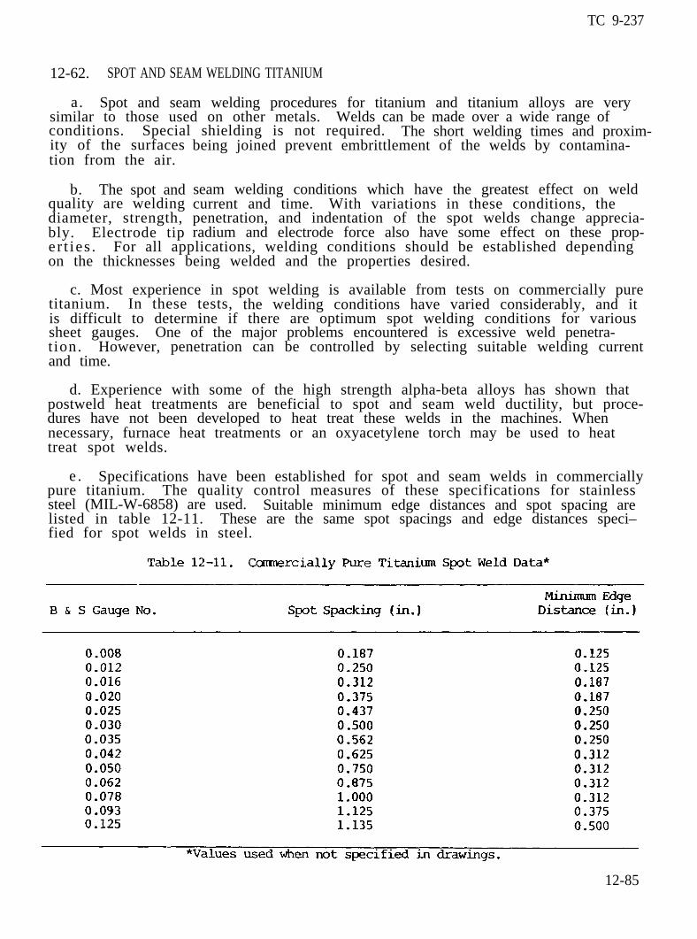
TC 9-237
12-62. SPOT AND SEAM WELDING TITANIUM
a. Spot and seam welding procedures for titanium and titanium alloys are verysimilar to those used on other metals. Welds can be made over a wide range ofconditions. Special shielding is not required. The short welding times and proxim-ity of the surfacestion from the air.
b. The spot andquality are weldingdiameter, strength,bly. Electrode tip
being joined prevent embrittlement of the welds by contamina-
seam welding conditions which have the greatest effect on weldcurrent and time. With variations in these conditions, thepenetration, and indentation of the spot welds change apprecia-radium and electrode force also have some effect on these prop-
er t ies . For all applications, welding conditions should be established dependingon the thicknesses being welded and the properties desired.
c. Most experience in spot welding is available from tests on commercially puretitanium. In these tests, the welding conditions have varied considerably, and itis difficult to determine if there are optimum spot welding conditions for varioussheet gauges. One of the major problems encountered is excessive weld penetra-t ion. However, penetration can be controlled by selecting suitable welding currentand time.
d. Experience with some of the high strength alpha-beta alloys has shown thatpostweld heat treatments are beneficial to spot and seam weld ductility, but proce-dures have not been developed to heat treat these welds in the machines. Whennecessary, furnace heat treatments or an oxyacetylene torch may be used to heattreat spot welds.
e . Specifications have been established for spot and seam welds in commerciallypure titanium. The quality control measures of these specifications for stainlesssteel (MIL-W-6858) are used. Suitable minimum edge distances and spot spacing arelisted in table 12-11. These are the same spot spacings and edge distances speci–fied for spot welds in steel.
12-85
TC 9-237
12-63. FLASH WELDING TITANIUM
a. Flash welding procedures for titanium are similar to those used for othermetals. As was the case for spot and seam welding, special shielding is not neces-sary to produce satisfactory flash welds. However, inert gas shielding has beenused to decrease the possibility of weld contamination and to increase ductility.For many of the high strength alloys, postweld heat treatments are required toprevent cracking and improve weld ductility. These welds are transferred to afurnace for heat treatment.
b. Flash welding conditions have varied considerably. However, short flashingcycles and fast upset speeds similar to those used for aluminum generally are em-ployed. The upset cycle is probably the most important variable, because of itseffect on the expulsion of contaminated metal from the joint. In some of the highstrength alpha-beta alloys, superior results were obtained by using intermediatepressures (8000 to 10,000 psi (55,160 to 68,950 kPa)).
NOTE High upset pressure results in high residual stresses that may causethe occurence of microfissures in the hard weld zones in these alloys.
c. An adopted specification requires the tensile strength of the weld area offlash welded joints to be 95 percent minimum of parent metal, and elongationthrough the weld area to be 50 percent minimum of parent material. With properwelding procedures and postweld treatment, flash welds in titanium and most of thetitanium alloys can be held to these criteria.
12-86