Embed Size (px)
Citation preview
TB 9-2300-247-40This bulletin supersedes TB 9-2300-247-40, 23 February 1971
TECHNICAL BULLETIN
TACTICAL WHEELED VEHICLES:
REPAIR OF FRAMES
Approved for public release; distribution is unlimited.
HEADQUARTERS, DEPARTMENT OF THE ARMY
4 December 1990
TB 9-2300-247-40
*TB 9-2300-247-40
DEPARTMENT OF THE ARMY TECHNICAL BULLETIN
TACTICAL WHEELED VEHICLESREPAIR OF FRAMES
Department of the Army, Washington, D.C.
4 December 1990
Paragraph Page
CHAPTER 1 GENERAL ........................................................................................................................ 2
Section I. General........................................................................................................ 2 2
Section II. Description of Vehicle Frames .................................................................... 4 2
Section III. General Inspection of Vehicle Frames ........................................................ 7 3
Section IV. Criteria for Frame Repair ............................................................................ 10 3
Section V. Welded Repairs........................................................................................... 19 6
CHAPTER 2. EQUIPMENT AND TOOLS .............................................................................................. 7
Section I. Equipment and Tools .................................................................................. 22 7
Section II. Fabricated Tools.......................................................................................... 24 7
CHAPTER 3. FRAME ALINEMENT INSPECTION ................................................................................ 8
Section I. 3/4 Ton to 2-1/2 Ton Series Vehicles.......................................................... 25 8
Section II. 5-Ton Series Vehicles ................................................................................. 28 8
CHAPTER 4. FRAME REPAIR PROCEDURES.................................................................................... 18
Section I. 3/4 Ton to 1-1/4 Ton Series Vehicle Frames .............................................. 38 18
Section II. 2-1/2 Ton Series Frames ............................................................................ 46 22
Section III. 5-Ton Series Vehicle Frames...................................................................... 47 26
Section IV. Welding of 5-Ton Vehicle Series Frames ......................................... .......... 50 34
*This bulletin supersedes TB 9-2300-247-40, 23 February 1971.
1
TB 9-2300-247-40
CHAPTER 1. GENERAL
SECTION I. GENERAL
1. Purpose. This bulletin provides information tofield maintenance personnel in the various methods oftactical wheeled vehicle frame repair.
2. Scope.
a. This bulletin contains descriptions, methodsand procedures for the inspection and therepair of cracked vehicle side rails, vehicleframe members, broken welds, bolts, andrivets and the fabrication of vehicle framereinforcement members.
b. The following family of wheeled vehicles areincluded as a part of this bulletin: CUCVSeries Vehicles, 3/4 to 1/4 Ton HMMMVSeries Vehicles, 1-1/4 Ton 2-1/2-TonSeries Vehicles 5-Ton Truck SeriesVehicles.
c. Vehicle frame repair is restricted to thecriteria specified in Section IV. Anyproposed repair which is not specificallyspecified in Sections IV and V, or notincluded as part of a work procedure in aspecific vehicle maintenance manual, is notauthorized and will not be considered.
d. Frame repairs are allocated to GeneralSupport (GS) and depot level maintenanceactivities. However, vehicles will not beevacuated to a maintenance depot solely
for the purpose of frame repair. SeeSection IV, paragraph 10.
e. Procedures for frame repair vary with thedifferent types and locations of frame defectof failure. The methods and success ofvehicle frame repair is dependent to a greatdegree on the skill and experience of thetechnician performing the work.. Manyframe repair procedures begin with verysimple steps. Often, removal andreplacement procedures in the area wherethe frame requires repair are left to theexperience of the mechanic. Othercomponent removal and replacementprocedures are strictly governed by theprocedures in the specific maintenancemanual for the vehicle frame under repair.Most types of cracked frames may berepaired provided the crack is located in anaccessible position allowing the repair to beperformed without complete disassembly ofthe vehicle. All vehicle frame repairs must,at a minimum be equal in strength to that ofthe original frame.
3. Reporting of Errors. The reporting of errors,omissions, and recommendations for improving thispublication by the individual user is encouraged. Reportsshould be submitted on DA Form 2028 (RecommendedChanges to Publications and Blank Forms) andforwarded direct to: Commander, U.S. Army Tank-Automotive Command, ATTN.: AMSTA-MB, Warren MI48397-5000.
SECTION II. DESCRIPTION OF VEHICLE FRAMES
4. Truck Frames. Truck frames are generallyconstructed of pressed steel channel side members andsteel crossmembers reinforced and stiffened with gussetplates and braces. In general, frames are assembled bybolting, riveting, and with welded joints, or with acombination of all these methods.
5. Heat-Treated Steel Frames. Heat-treated steelframes, such as those used in 5-ton trucks are
assembled using bolts and rivets. Most weldingprocesses destroy the heat treatment properties of thevehicle framing members, causing the metal adjacent tothe weld to be weakened. As a result of the destructiveproperties of welding on heat-treated steel, welding ofheat-treated 5-ton truck framing members is prohibitedexcept as otherwise specified in Chapter 5.
2
TB 9-2300-247-40
NOTEFor illustrations of specific vehicleframes, refer to the maintenancemanual for the vehicle frameproposed for repair.
6. 3/4 to 1-1/4 Ton Series Vehicle Frames.
All frames used in 3/4-ton, 1-1/4-ton to 2-1/2-ton seriesvehicles are fabricated of medium or low carbon steel.The various steel framing members are frequently joinedtogether by welding during initial vehicle production.Future repairs to these frames by welding is permitted ifthe procedures specified in this manual are strictly andcarefully followed.
SECTION III. GENERAL INSPECTION OF VEHICLE FRAMES
7. Riveted Frame Connections. Perform thefollowing inspection of rivet-assembled vehicle framingmembers:
a. Using a .001 inch thick feeler gage, checkfor space between rivet head and theriveted frame members Penetration of thefeeler gage between the rivet head and theriveted member is reason to suspect thatthe riveted connection and/or rivet shouldbe replaced.
b. Thoroughly clean rivet and rivetedconnection of all dirt, grease and oil. Usingan oil can, apply lubricating oil around thesuspect rivet and riveted connection. Allowapproximately 10 to 20 seconds for the oilto penetrate. Wipe rivet and rivetedconnection free of oil. Tap rivet with aneight pound hammer. Any indication of oilaround the rivet indicates a loose rivet.Replace all loose rivets. Check all rivetedconnections for signs of movement, such
as bare or shiny spots, or other indicationsof movement between rivet and framingmember. If movement is indicated, rivetand connection are loose. Repair all looseconnections.
8. Bolted Frame Connections. Perform thefollowing inspection of frame bolted connections:
a. Check bolts and nuts for tightness andproper mating with frame surfaces.
b. Check the torque of all bolts not scheduledto be removed in accordance with appendixE of the appropriate vehicle TM.
9. Welded Frame Connections. Perform thefollowing inspection of frame welded connections:
Where welds are found on the vehicle,check welds for integrity, deteriorationand flaking.
SECTION IV. CRITERIA FOR FRAME REPAIR
10. Frame Deficiencies. Frame deficiencies willonly be considered for repair under the followingconditions: Costs. Total estimated cost of any proposedframe repair, including the frame deficiency and all othermiscellaneous repairs fall within the maximum repairexpenditure limits specified in TB 43-0001. Framedamage will be carefully evaluated to determine the
extent of repair required, including all operationsincidental to the repair, and those costs, combined withall other costs required to provide a completelyserviceable frame. If there is any doubt that the frame isnon-repairable, the final decision will be made by thelocal Logistics Assistance Representative (LAR).
3
TB 9-2300-247-40
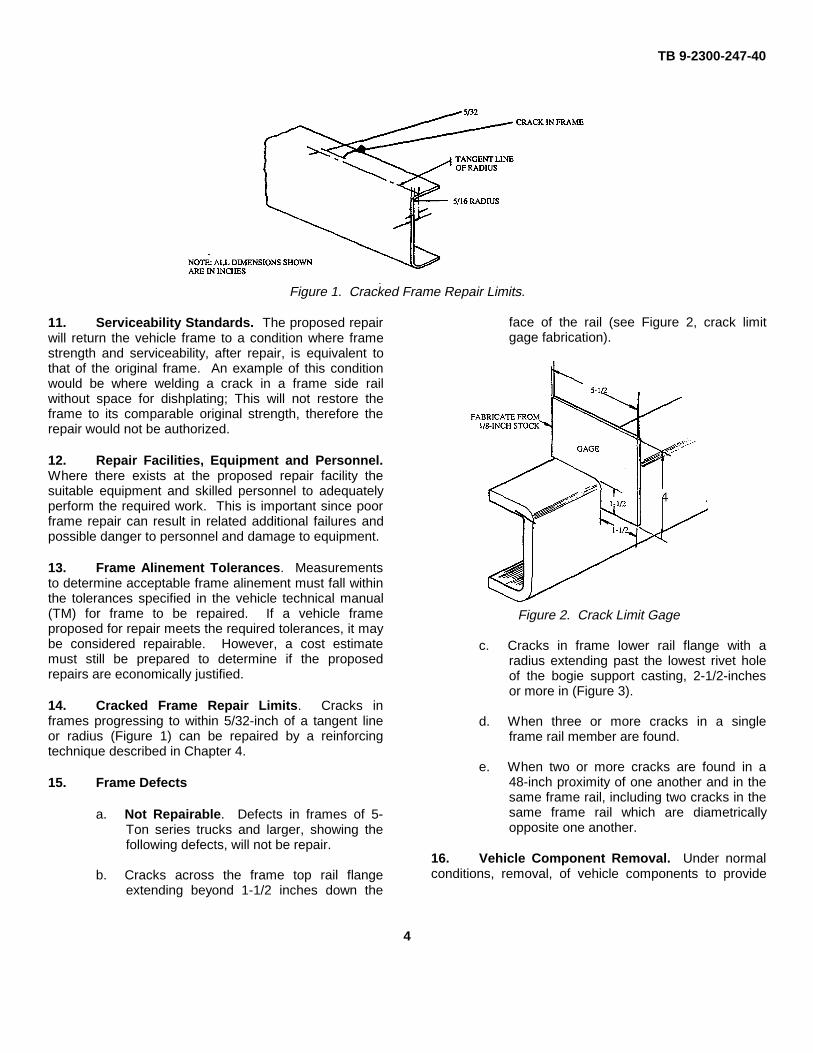
Figure 1. Cracked Frame Repair Limits.
11. Serviceability Standards. The proposed repairwill return the vehicle frame to a condition where framestrength and serviceability, after repair, is equivalent tothat of the original frame. An example of this conditionwould be where welding a crack in a frame side railwithout space for dishplating; This will not restore theframe to its comparable original strength, therefore therepair would not be authorized.
12. Repair Facilities, Equipment and Personnel.Where there exists at the proposed repair facility thesuitable equipment and skilled personnel to adequatelyperform the required work. This is important since poorframe repair can result in related additional failures andpossible danger to personnel and damage to equipment.
13. Frame Alinement Tolerances. Measurementsto determine acceptable frame alinement must fall withinthe tolerances specified in the vehicle technical manual(TM) for frame to be repaired. If a vehicle frameproposed for repair meets the required tolerances, it maybe considered repairable. However, a cost estimatemust still be prepared to determine if the proposedrepairs are economically justified.
14. Cracked Frame Repair Limits. Cracks inframes progressing to within 5/32-inch of a tangent lineor radius (Figure 1) can be repaired by a reinforcingtechnique described in Chapter 4.
15. Frame Defects
a. Not Repairable. Defects in frames of 5-Ton series trucks and larger, showing thefollowing defects, will not be repair.
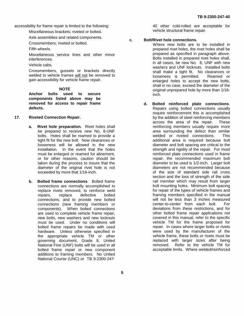
b. Cracks across the frame top rail flangeextending beyond 1-1/2 inches down the
face of the rail (see Figure 2, crack limitgage fabrication).
Figure 2. Crack Limit Gage
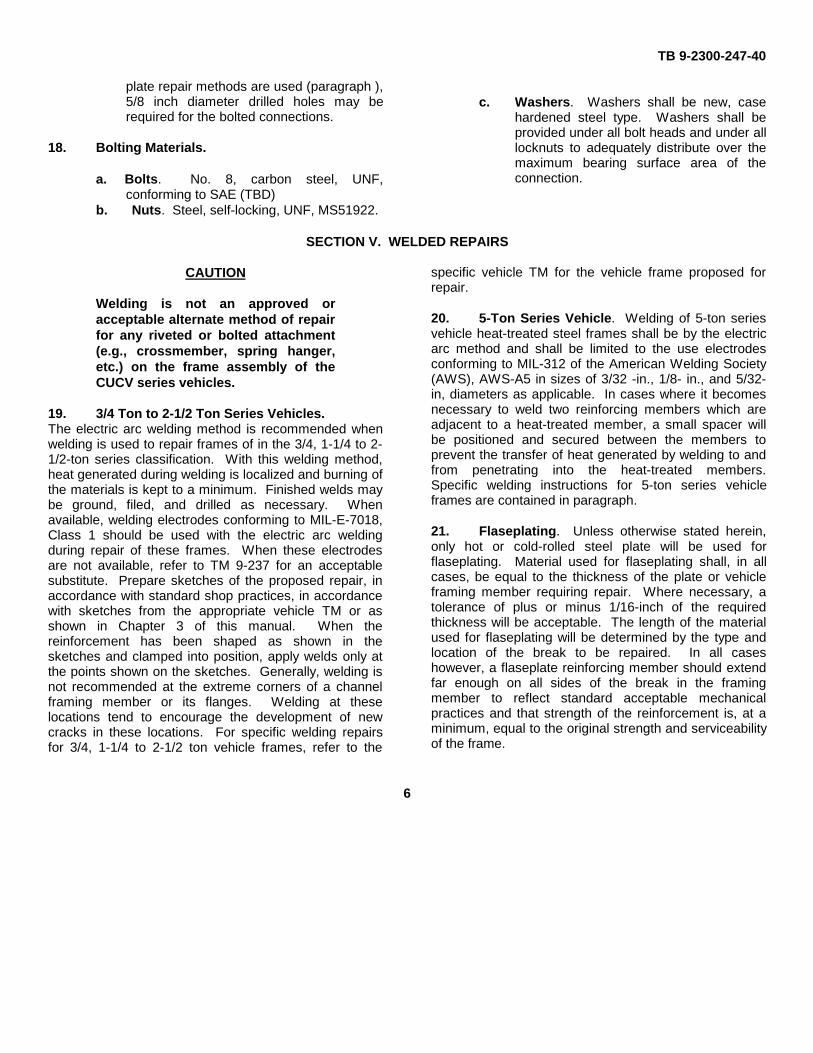
c. Cracks in frame lower rail flange with aradius extending past the lowest rivet holeof the bogie support casting, 2-1/2-inchesor more in (Figure 3).
d. When three or more cracks in a singleframe rail member are found.
e. When two or more cracks are found in a48-inch proximity of one another and in thesame frame rail, including two cracks in thesame frame rail which are diametricallyopposite one another.
16. Vehicle Component Removal. Under normalconditions, removal, of vehicle components to provide
4
TB 9-2300-247-40
accessibility for frame repair is limited to the following:
Miscellaneous brackets; riveted or bolted.
Axle assemblies and related components.
Crossmembers; riveted or bolted.
Fifth wheels.
Miscellaneous service lines and other minorinterferences.
Vehicle cabs.
Crossmembers, gussets or brackets directlywelded to vehicle frames will not be removed togain accessibility for vehicle frame repair.
NOTEAnchor bolts used to securecomponents listed above may beremoved for access to repair framedefects.
17. Riveted Connection Repair.
a. Rivet hole preparation. Rivet holes shallbe prepared to receive new No, 8-UNFbolts. Holes shall be reamed to provide atight fit for the new bolt. Now clearances orlooseness will be allowed in the newinstallation. In the event that the holesmust be enlarged or reamed for alinement,or for other reasons, caution should betaken during the process to insure that thediameter of the original rivet hole is notexceeded by more that 1/16-inch.
b. Bolted frame connections. Bolted frameconnections are normally accomplished toreplace rivets removed, to reinforce weldrepairs, replace defective boltedconnections, and to provide new boltedconnections (new framing members orcomponents). When bolted connectionsare used to complete vehicle frame repair,new bolts, new washers and new locknutsmust be used. Under no conditions willbolted frame repairs be made with usedhardware. Unless otherwise specified inthe appropriate vehicle TM or othergoverning document, Grade 8, UnitedNational Fine (UNF) bolts will be used in allbolted frame repair or new componentadditions to framing members. No UnitedNational Course (UNC) or TB 9-2300-247-
40 other cold-rolled are acceptable forvehicle structural frame repair.
c. Bolt/Rivet hole connections.Where new bolts are to be installed inprepared rivet holes, the rivet holes shall beprepared as specified in paragraph above.Bolts installed in prepared rivet holes shall,in all cases, be new No. 8, UNF with newwashers and UNF locknuts. Installed boltsshall make a tight fit. No clearances orlooseness is permitted. Reamed orenlarged holes to accept the new bolts,shall in no case, exceed the diameter of theoriginal unprepared hole by more than 1/16-inch.
d. Bolted reinforced plate connections.Repairs using bolted connections usuallyrequire reinforcement this is accomplishedby the addition of steel reinforcing membersacross the area of the repair. Thesereinforcing members usually require morearea surrounding the defect than similarwelded or riveted connections. Thisadditional area is required because boltdiameter and bolt spacing are critical to thestrength and rigidity of the repair. For mostreinforced plate connections used in framerepair, the recommended maximum boltdiameter to be used is 1/2-inch. Larger boltdiameters are not recommended becauseof the size of standard side rail crosssection and the loss of strength of the siderail member which may result from largerbolt mounting holes. Minimum bolt spacingfor repair of the types of vehicle frames andframing members specified in the manualwill not be less than 3 inches measuredcenter-to-center from each bolt. Fordeviations from these restrictions, and forother bolted frame repair applications notcovered in this manual, refer to the specificvehicle TM for the frame proposed forrepair. In cases where larger bolts or rivetswere used by the manufacturer of thevehicle frame, these bolts or rivets must bereplaced with larger sizes after beingremoved. Refer to the vehicle TM foracceptable limits. Where welded/reinforced
5
TB 9-2300-247-40
plate repair methods are used (paragraph ),5/8 inch diameter drilled holes may berequired for the bolted connections.
18. Bolting Materials.
a. Bolts. No. 8, carbon steel, UNF,conforming to SAE (TBD)
b. Nuts. Steel, self-locking, UNF, MS51922.
c. Washers. Washers shall be new, casehardened steel type. Washers shall beprovided under all bolt heads and under alllocknuts to adequately distribute over themaximum bearing surface area of theconnection.
SECTION V. WELDED REPAIRS
CAUTION
Welding is not an approved oracceptable alternate method of repairfor any riveted or bolted attachment(e.g., crossmember, spring hanger,etc.) on the frame assembly of theCUCV series vehicles.
19. 3/4 Ton to 2-1/2 Ton Series Vehicles.The electric arc welding method is recommended whenwelding is used to repair frames of in the 3/4, 1-1/4 to 2-1/2-ton series classification. With this welding method,heat generated during welding is localized and burning ofthe materials is kept to a minimum. Finished welds maybe ground, filed, and drilled as necessary. Whenavailable, welding electrodes conforming to MIL-E-7018,Class 1 should be used with the electric arc weldingduring repair of these frames. When these electrodesare not available, refer to TM 9-237 for an acceptablesubstitute. Prepare sketches of the proposed repair, inaccordance with standard shop practices, in accordancewith sketches from the appropriate vehicle TM or asshown in Chapter 3 of this manual. When thereinforcement has been shaped as shown in thesketches and clamped into position, apply welds only atthe points shown on the sketches. Generally, welding isnot recommended at the extreme corners of a channelframing member or its flanges. Welding at theselocations tend to encourage the development of newcracks in these locations. For specific welding repairsfor 3/4, 1-1/4 to 2-1/2 ton vehicle frames, refer to the
specific vehicle TM for the vehicle frame proposed forrepair.
20. 5-Ton Series Vehicle. Welding of 5-ton seriesvehicle heat-treated steel frames shall be by the electricarc method and shall be limited to the use electrodesconforming to MIL-312 of the American Welding Society(AWS), AWS-A5 in sizes of 3/32 -in., 1/8- in., and 5/32-in, diameters as applicable. In cases where it becomesnecessary to weld two reinforcing members which areadjacent to a heat-treated member, a small spacer willbe positioned and secured between the members toprevent the transfer of heat generated by welding to andfrom penetrating into the heat-treated members.Specific welding instructions for 5-ton series vehicleframes are contained in paragraph.
21. Flaseplating. Unless otherwise stated herein,only hot or cold-rolled steel plate will be used forflaseplating. Material used for flaseplating shall, in allcases, be equal to the thickness of the plate or vehicleframing member requiring repair. Where necessary, atolerance of plus or minus 1/16-inch of the requiredthickness will be acceptable. The length of the materialused for flaseplating will be determined by the type andlocation of the break to be repaired. In all caseshowever, a flaseplate reinforcing member should extendfar enough on all sides of the break in the framingmember to reflect standard acceptable mechanicalpractices and that strength of the reinforcement is, at aminimum, equal to the original strength and serviceabilityof the frame.
6
TB 9-2300-247-40
Figure 3. Unrepairable Frame Rail
CHAPTER 2
EQUIPMENT AND TOOLS
SECTION I. EQUIPMENT AND TOOLS
22. Equipment.The necessary equipment to accomplish frame repairsdescribed in this manual are available at all fieldmaintenance level activities.
23. Tools. The tools necessary to perform vehicleframe repairs described in this manual are available at allfield maintenance level activities which is describedunder fabricated tools below.
SECTION II. FABRICATED TOOLS
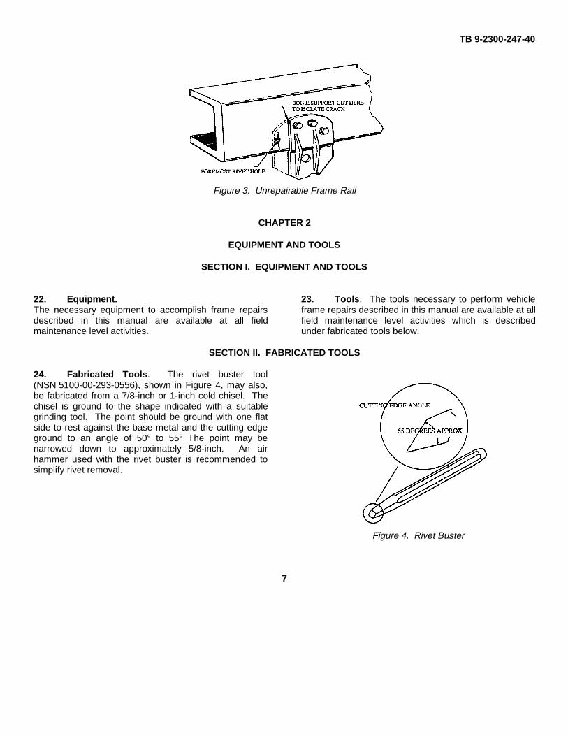
24. Fabricated Tools. The rivet buster tool(NSN 5100-00-293-0556), shown in Figure 4, may also,be fabricated from a 7/8-inch or 1-inch cold chisel. Thechisel is ground to the shape indicated with a suitablegrinding tool. The point should be ground with one flatside to rest against the base metal and the cutting edgeground to an angle of 50° to 55° The point may benarrowed down to approximately 5/8-inch. An airhammer used with the rivet buster is recommended tosimplify rivet removal.
Figure 4. Rivet Buster
7
TB 9-2300-247-40
CHAPTER 3
FRAME ALINEMENT INSPECTION
SECTION I. 3/4, AND 1-1/4 TON TO 2-1/2 TON SERIES VEHICLE REQUIREMENTS
Tools: Light:Extension, 25 ft. lengthJack, Hydraulic, 12-ton capacityJack, Hydraulic, 30-ton capacityPlumb Bob, 10 oz.Square, 24 in.Tape Measure, 25 ft. long
Expendable Supplies:Paper, white, 8 x 10⁻¹/2 sheetsFitting, GreasePencilString, 12-ply, 25 ft. longTape, Masking, 1 in. wide
25. Shop Conditions: Floor level with slope notmore than 3 inches in 24 feet in any direction, Floorsurface must be flat within 1 inch in 24 feet. Floor cleanof dirt, grease, oil, or debris.
26. Equipment Condition: Vehicle empty andvehicle undercarriage clean and completely free of mud,dirt, and debris.
27. 3/4, 1-1/4 and To 2-1/2 Ton Vehicle SeriesFrames.
a. CUCV Series Vehicle Frame AlinementInspection.
Applicable Vehicle Models/Series: M966, M996,M997, M998, M1008, M1008A1,M1009, M1010, M1025, M1026, M1028,M1028A1, M1028A2, M1035, M1036, M1037,M1038, M1042, M1043, M1044, M1045,M1046.
Reference Publications: TM 9-2320-289-34
(1) Perform Frame Leveling in accordancewith paragraphs 27a. thru 27g. andfigures 5 and 6.
(2) Perform all other frame alinementchecks as described in paragraphs 27thru 31.
b. HMMMV Series Vehicle Frame AlinementInspection.
Applicable Vehicle Models/Series: M998, M966,M1036, M1045, M1046, M1025, M1026, M1043, M1044,M1037, M1042,
Reference Publications: TM 9-2320-280-34
(1) Perform frame leveling as described inparagraphs 27a. thru 27g. and figures 5and 6.
(2) Perform all other frame alinement checks inaccordance with paragraphs 27 thru 31.
SECTION II. 5-TON SERIES VEHICLES REQUIREMENTS
Applicable Vehicle Models/Series: M39, M39A1,M39A2, M809 and M939 Series
Tools: Light:
Extension, 25 ft. lengthJack, Hydraulic, 12-ton capacityJack, Hydraulic, 30-ton capacityPlumb Bob, 10 oz.Square, 24 in.Tape Measure, 25 ft. Long
Expendable Supplies:
Paper, white, 8 x 10⁻¹/2 sheetsFitting, GreasePencilString, 12-ply, 25 ft. longTape, Masking, 1 in. wide
28. Shop Conditions: Floor level with slope notmore than 3 inches in 24 feet in any direction. Floorsurface must be flat within 1 inch in 24 feet. Floor cleanof dirt, grease, oil, or debris.
8
TB 9-2300-247-40
29. Equipment Conditions: Vehicle empty andvehicle undercarriage clean and completely free of mud,dirt, and debris.
Reference Publications:
TM 9-2320-211-34-22TM 9-2320-260-34-2-3TM 9-2320-272-34-1TM 9-2320-272-34-2
30. Undercarriage Preliminary Inspection.
NOTEIf damage is found during theundercarriage preliminary inspection,this damage must be correctedbefore vehicle frame alinement canbe completed.
a. Perform the following checks:
(1) Check for loose or missingcrossmember rivets.
(2) Check for loose or brokencrossmembers.
(3) Check for damaged frame rails.
b. Drive vehicle into inspection position from a12 foot straight line of travel.
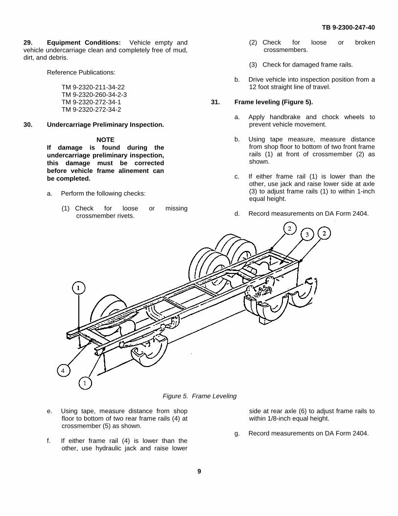
31. Frame leveling (Figure 5).
a. Apply handbrake and chock wheels toprevent vehicle movement.
b. Using tape measure, measure distancefrom shop floor to bottom of two front framerails (1) at front of crossmember (2) asshown.
c. If either frame rail (1) is lower than theother, use jack and raise lower side at axle(3) to adjust frame rails (1) to within 1-inchequal height.
d. Record measurements on DA Form 2404.
Figure 5. Frame Leveling
e. Using tape, measure distance from shopfloor to bottom of two rear frame rails (4) atcrossmember (5) as shown.
f. If either frame rail (4) is lower than theother, use hydraulic jack and raise lower
side at rear axle (6) to adjust frame rails towithin 1/8-inch equal height.
g. Record measurements on DA Form 2404.
9
TB 9-2300-247-40
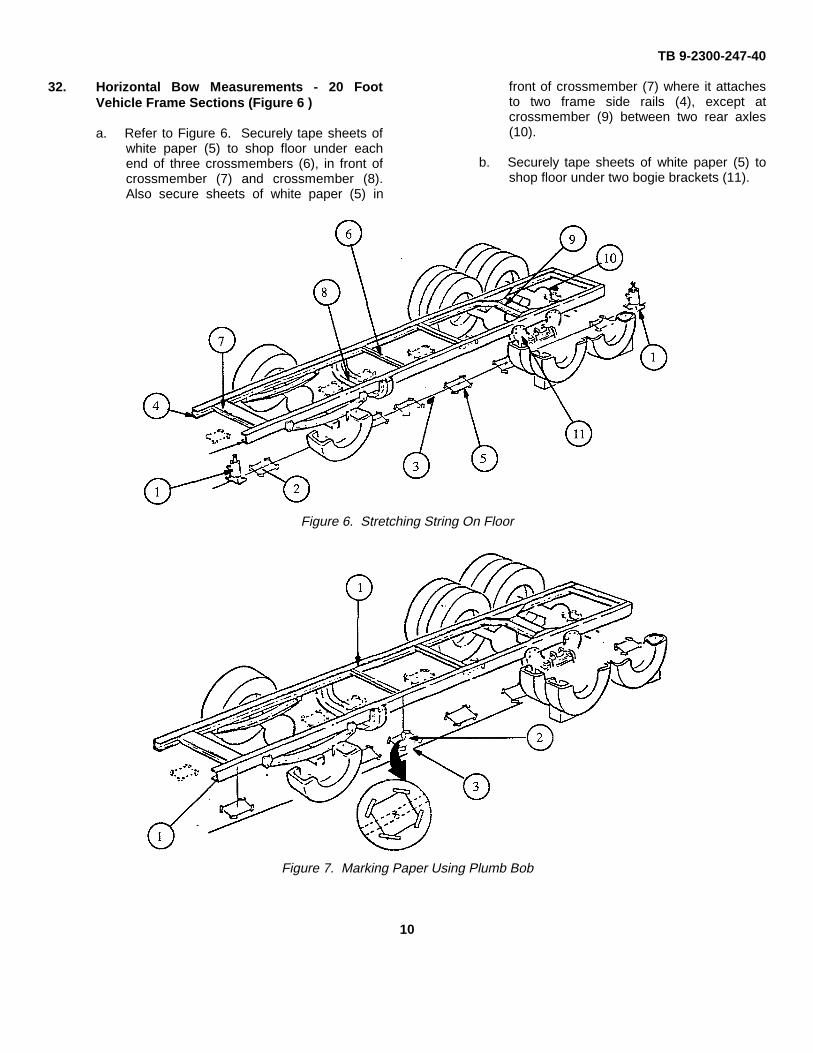
32. Horizontal Bow Measurements - 20 FootVehicle Frame Sections (Figure 6 )
a. Refer to Figure 6. Securely tape sheets ofwhite paper (5) to shop floor under eachend of three crossmembers (6), in front ofcrossmember (7) and crossmember (8).Also secure sheets of white paper (5) in
front of crossmember (7) where it attachesto two frame side rails (4), except atcrossmember (9) between two rear axles(10).
b. Securely tape sheets of white paper (5) toshop floor under two bogie brackets (11).
Figure 6. Stretching String On Floor
Figure 7. Marking Paper Using Plumb Bob
10
TB 9-2300-247-40
NOTETo ensure accurate measurements,check that plumb bob string is placedflat against frame rails, is free ofobstructions such as bolts, nuts,rivets, brackets, and rear springs.
c. Refer to Figure 7. Hold string of plumb bob(2) above paper (3) to outside of frame rail(1) making sure that plumb bob string isplaced flat and unobstructed against framerails.
d. Adjust plumb bob (2) to hang above paper(3), 4 inches from bottom of frame rail (1).
e. Carefully locate a fixed point on paper (3)directly below plumb bob (2).
f. Using pencil, carefully mark fixed point onpaper (3) directly below plumb bob (2)point.
g. Leave papers (3) with fixed point marks inplace for next procedure.
h. Repeat steps a thru g above for other framerail (1).
i. Leave papers (3) with fixed point (5) marksin place for next procedure.
j. Refer to Figure 6. Stretch string (3) tightlyon the shop floor between the front andrear plumb bob fixed point marks (2) undereach frame rail (4). Place hydraulic jacks(1) on string (3) to keep string tight.
NOTEStrings used for horizontal bowmeasurements will remain in placeuntil the frame squareness task iscompleted. On vehicle frames longerthan 20 feet, the two front to rearstrings will be used.
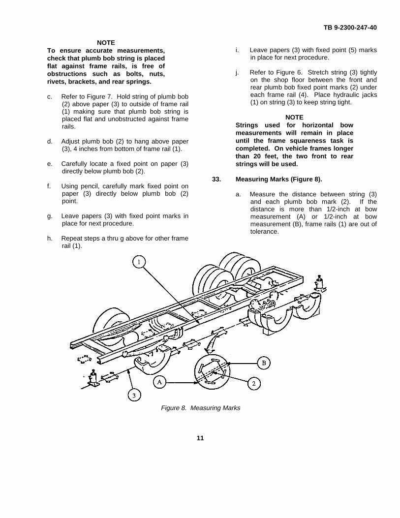
33. Measuring Marks (Figure 8).
a. Measure the distance between string (3)and each plumb bob mark (2). If thedistance is more than 1/2-inch at bowmeasurement (A) or 1/2-inch at bowmeasurement (B), frame rails (1) are out oftolerance.
Figure 8. Measuring Marks
11
TB 9-2300-247-40
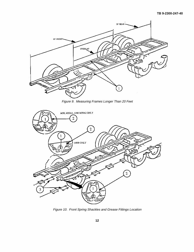
Figure 9. Measuring Frames Longer Than 20 Feet
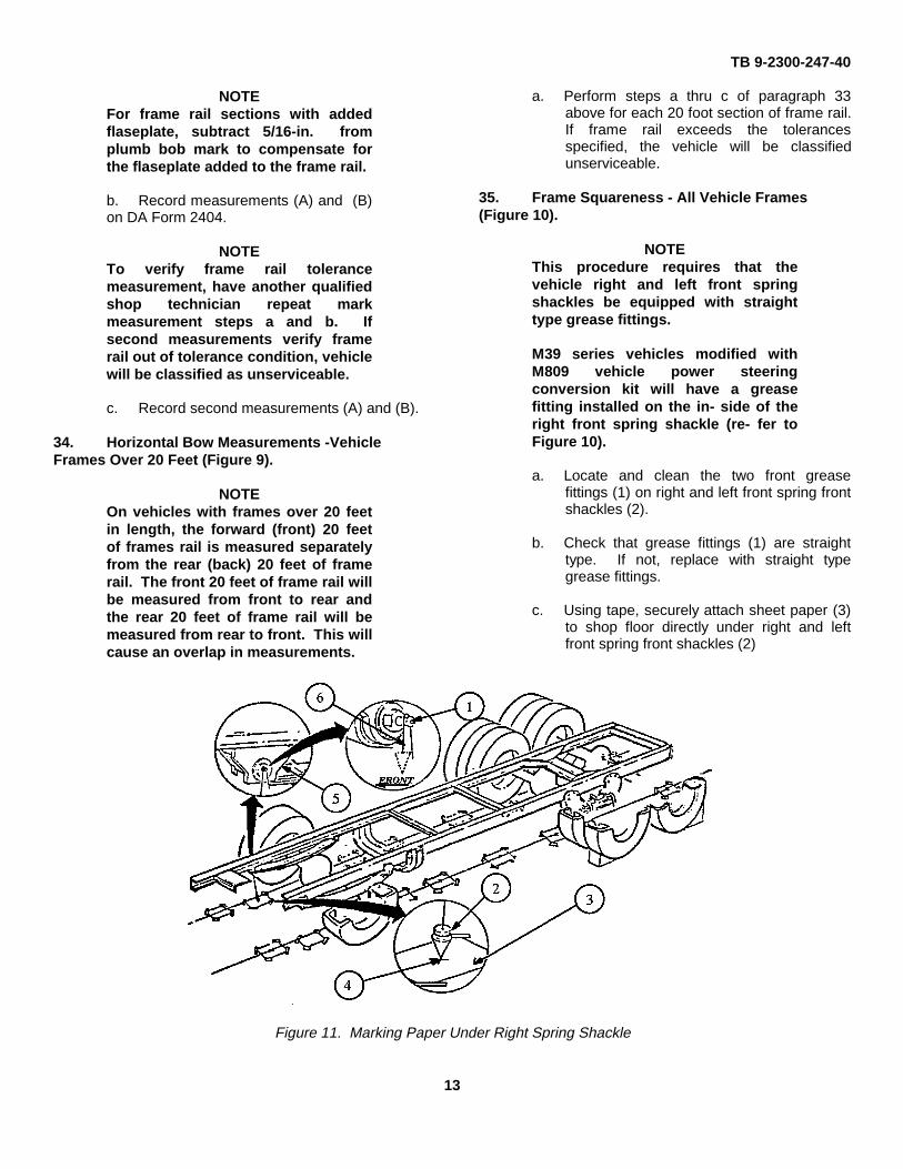
Figure 10. Front Spring Shackles and Grease Fittings Location
12
TB 9-2300-247-40
NOTEFor frame rail sections with addedflaseplate, subtract 5/16-in. fromplumb bob mark to compensate forthe flaseplate added to the frame rail.
b. Record measurements (A) and (B)on DA Form 2404.
NOTETo verify frame rail tolerancemeasurement, have another qualifiedshop technician repeat markmeasurement steps a and b. Ifsecond measurements verify framerail out of tolerance condition, vehiclewill be classified as unserviceable.
c. Record second measurements (A) and (B).
34. Horizontal Bow Measurements -VehicleFrames Over 20 Feet (Figure 9).
NOTEOn vehicles with frames over 20 feetin length, the forward (front) 20 feetof frames rail is measured separatelyfrom the rear (back) 20 feet of framerail. The front 20 feet of frame rail willbe measured from front to rear andthe rear 20 feet of frame rail will bemeasured from rear to front. This willcause an overlap in measurements.
a. Perform steps a thru c of paragraph 33above for each 20 foot section of frame rail.If frame rail exceeds the tolerancesspecified, the vehicle will be classifiedunserviceable.
35. Frame Squareness - All Vehicle Frames(Figure 10).
NOTEThis procedure requires that thevehicle right and left front springshackles be equipped with straighttype grease fittings.
M39 series vehicles modified withM809 vehicle power steeringconversion kit will have a greasefitting installed on the in- side of theright front spring shackle (re- fer toFigure 10).
a. Locate and clean the two front greasefittings (1) on right and left front spring frontshackles (2).
b. Check that grease fittings (1) are straighttype. If not, replace with straight typegrease fittings.
c. Using tape, securely attach sheet paper (3)to shop floor directly under right and leftfront spring front shackles (2)
Figure 11. Marking Paper Under Right Spring Shackle
13
TB 9-2300-247-40
NOTEIf plumb bob is not placed towardsthe front of the vehicle on both theright and the left grease fittings (1),inaccurate frame squarenessmeasurement will result.
d. Refer to Figure 11. Place string (6) overgrease fitting (1) on inner right front springshackle (5). Make sure that plumb bob (2)is to front of vehicle.
e. Lower plumb bob (2) and locate a point onpaper (3) below spring shackle (5).
NOTEFor accuracy, do not make mark onpaper until plumb bob has stoppedswinging and is as close to the paperas possible without actually touchingthe paper.
f. Refer to Figure 11. Carefully mark spot (4)on paper (3) directly below plumb bob (2).
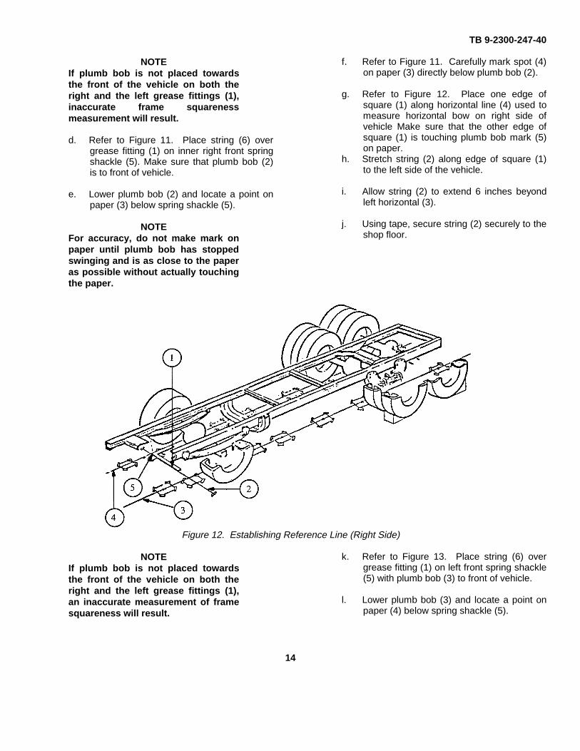
g. Refer to Figure 12. Place one edge ofsquare (1) along horizontal line (4) used tomeasure horizontal bow on right side ofvehicle Make sure that the other edge ofsquare (1) is touching plumb bob mark (5)on paper.
h. Stretch string (2) along edge of square (1)to the left side of the vehicle.
i. Allow string (2) to extend 6 inches beyondleft horizontal (3).
j. Using tape, secure string (2) securely to theshop floor.
Figure 12. Establishing Reference Line (Right Side)
NOTEIf plumb bob is not placed towardsthe front of the vehicle on both theright and the left grease fittings (1),an inaccurate measurement of framesquareness will result.
k. Refer to Figure 13. Place string (6) overgrease fitting (1) on left front spring shackle(5) with plumb bob (3) to front of vehicle.
l. Lower plumb bob (3) and locate a point onpaper (4) below spring shackle (5).
14
TB 9-2300-247-40
Figure 13. Marking Paper Under Left Spring Shackle
NOTEFor accuracy, do not make mark onpaper until plumb bob has stoppedswinging, is motionless, and is asclose to the paper as possiblewithout actually touching the paper.
m. Refer to Figure 13. Carefully mark a spot(5) on paper (4) directly below plumb bobpoint (3).
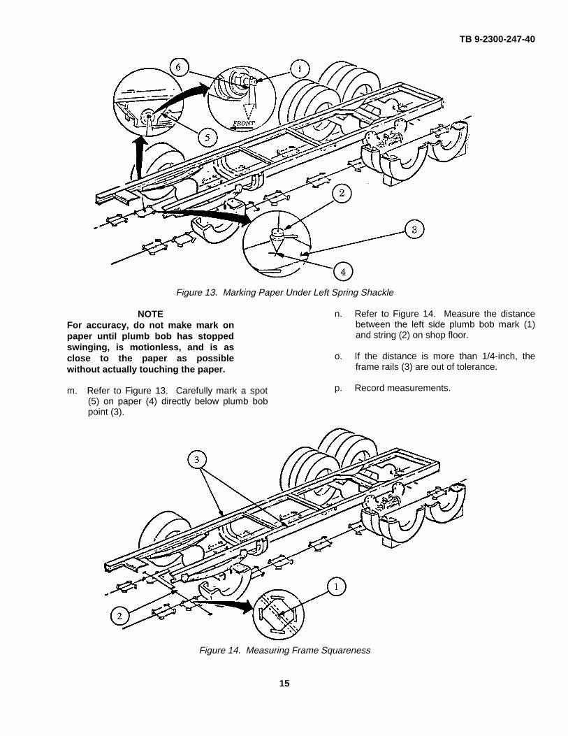
n. Refer to Figure 14. Measure the distancebetween the left side plumb bob mark (1)and string (2) on shop floor.
o. If the distance is more than 1/4-inch, theframe rails (3) are out of tolerance.
p. Record measurements.
Figure 14. Measuring Frame Squareness
15
TB 9-2300-247-40
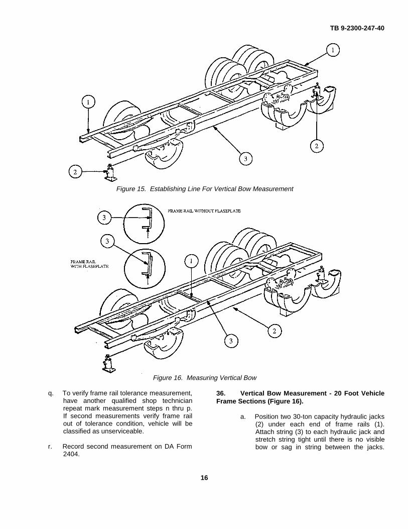
Figure 15. Establishing Line For Vertical Bow Measurement
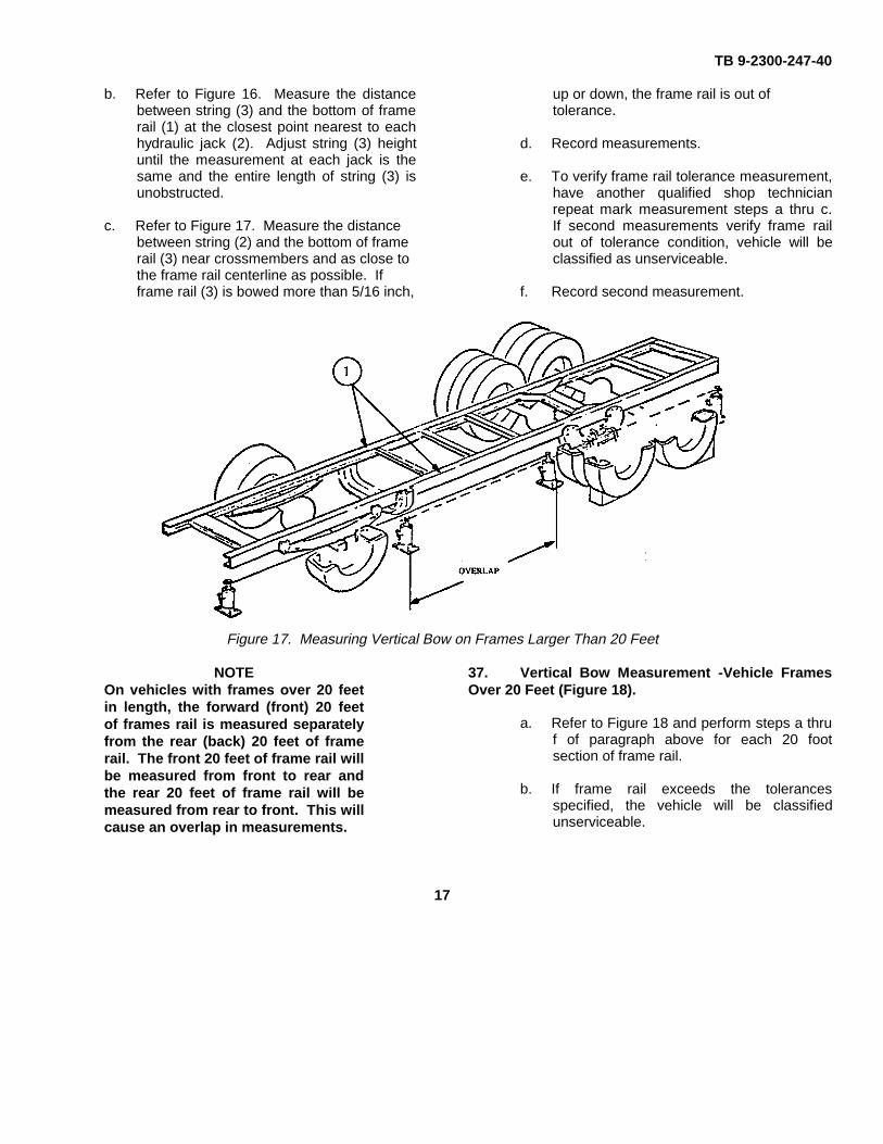
Figure 16. Measuring Vertical Bow
q. To verify frame rail tolerance measurement,have another qualified shop technicianrepeat mark measurement steps n thru p.If second measurements verify frame railout of tolerance condition, vehicle will beclassified as unserviceable.
r. Record second measurement on DA Form2404.
36. Vertical Bow Measurement - 20 Foot VehicleFrame Sections (Figure 16).
a. Position two 30-ton capacity hydraulic jacks(2) under each end of frame rails (1).Attach string (3) to each hydraulic jack andstretch string tight until there is no visiblebow or sag in string between the jacks.
16
TB 9-2300-247-40
b. Refer to Figure 16. Measure the distancebetween string (3) and the bottom of framerail (1) at the closest point nearest to eachhydraulic jack (2). Adjust string (3) heightuntil the measurement at each jack is thesame and the entire length of string (3) isunobstructed.
c. Refer to Figure 17. Measure the distancebetween string (2) and the bottom of framerail (3) near crossmembers and as close tothe frame rail centerline as possible. Ifframe rail (3) is bowed more than 5/16 inch,
up or down, the frame rail is out oftolerance.
d. Record measurements.
e. To verify frame rail tolerance measurement,have another qualified shop technicianrepeat mark measurement steps a thru c.If second measurements verify frame railout of tolerance condition, vehicle will beclassified as unserviceable.
f. Record second measurement.
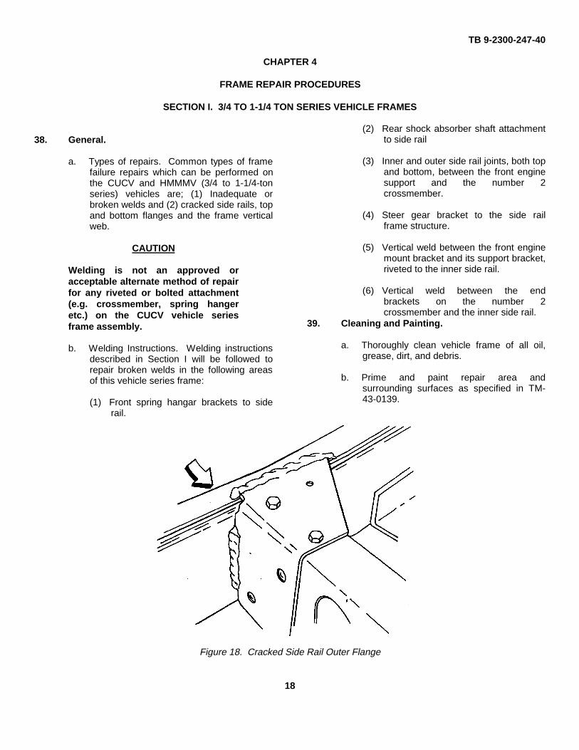
Figure 17. Measuring Vertical Bow on Frames Larger Than 20 Feet
NOTEOn vehicles with frames over 20 feetin length, the forward (front) 20 feetof frames rail is measured separatelyfrom the rear (back) 20 feet of framerail. The front 20 feet of frame rail willbe measured from front to rear andthe rear 20 feet of frame rail will bemeasured from rear to front. This willcause an overlap in measurements.
37. Vertical Bow Measurement -Vehicle FramesOver 20 Feet (Figure 18).
a. Refer to Figure 18 and perform steps a thruf of paragraph above for each 20 footsection of frame rail.
b. If frame rail exceeds the tolerancesspecified, the vehicle will be classifiedunserviceable.
17
TB 9-2300-247-40
CHAPTER 4
FRAME REPAIR PROCEDURES
SECTION I. 3/4 TO 1-1/4 TON SERIES VEHICLE FRAMES
38. General.
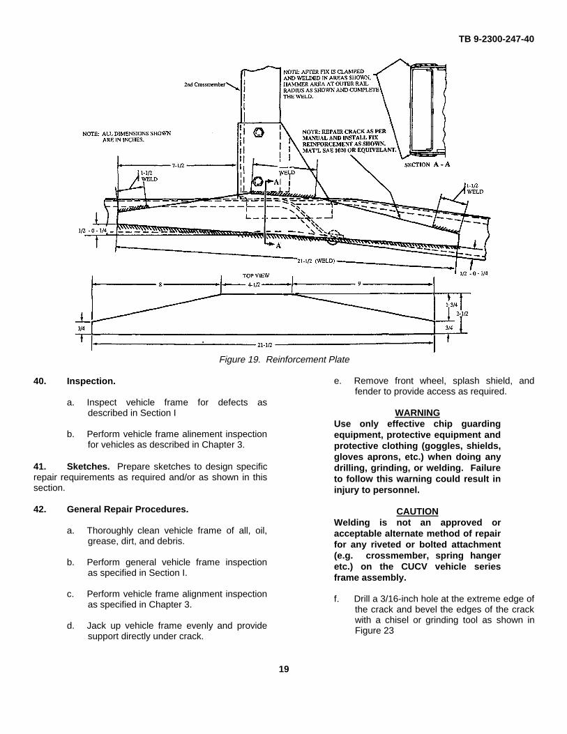
a. Types of repairs. Common types of framefailure repairs which can be performed onthe CUCV and HMMMV (3/4 to 1-1/4-tonseries) vehicles are; (1) Inadequate orbroken welds and (2) cracked side rails, topand bottom flanges and the frame verticalweb.
CAUTION
Welding is not an approved oracceptable alternate method of repairfor any riveted or bolted attachment(e.g. crossmember, spring hangeretc.) on the CUCV vehicle seriesframe assembly.
b. Welding Instructions. Welding instructionsdescribed in Section I will be followed torepair broken welds in the following areasof this vehicle series frame:
(1) Front spring hangar brackets to siderail.
(2) Rear shock absorber shaft attachmentto side rail
(3) Inner and outer side rail joints, both topand bottom, between the front enginesupport and the number 2crossmember.
(4) Steer gear bracket to the side railframe structure.
(5) Vertical weld between the front enginemount bracket and its support bracket,riveted to the inner side rail.
(6) Vertical weld between the endbrackets on the number 2crossmember and the inner side rail.
39. Cleaning and Painting.
a. Thoroughly clean vehicle frame of all oil,grease, dirt, and debris.
b. Prime and paint repair area andsurrounding surfaces as specified in TM-43-0139.
Figure 18. Cracked Side Rail Outer Flange
18
TB 9-2300-247-40
Figure 19. Reinforcement Plate
40. Inspection.
a. Inspect vehicle frame for defects asdescribed in Section I
b. Perform vehicle frame alinement inspectionfor vehicles as described in Chapter 3.
41. Sketches. Prepare sketches to design specificrepair requirements as required and/or as shown in thissection.
42. General Repair Procedures.
a. Thoroughly clean vehicle frame of all, oil,grease, dirt, and debris.
b. Perform general vehicle frame inspectionas specified in Section I.
c. Perform vehicle frame alignment inspectionas specified in Chapter 3.
d. Jack up vehicle frame evenly and providesupport directly under crack.
e. Remove front wheel, splash shield, andfender to provide access as required.
WARNINGUse only effective chip guardingequipment, protective equipment andprotective clothing (goggles, shields,gloves aprons, etc.) when doing anydrilling, grinding, or welding. Failureto follow this warning could result ininjury to personnel.
CAUTIONWelding is not an approved oracceptable alternate method of repairfor any riveted or bolted attachment(e.g. crossmember, spring hangeretc.) on the CUCV vehicle seriesframe assembly.
f. Drill a 3/16-inch hole at the extreme edge ofthe crack and bevel the edges of the crackwith a chisel or grinding tool as shown inFigure 23
19
TB 9-2300-247-40
g. Apply weld as required and ground flushwith surrounding metal.
h. Fabricate reinforcement plate of 1/4-inchcold-rolled steel plate as detailed in Figure20.
i. Position fabricated steel plate over crackflush with side member.
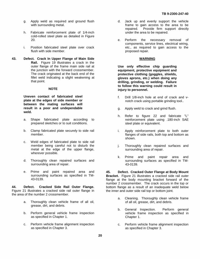
43. Defect. Crack In Upper Flange of Main SideRail. Figure 19 illustrates a crack in theouter flange of the frame main side rail atthe junction with the forward crossmember.The crack originated at the back end of thefillet weld indicating a slight weakening atthat point.
NOTE
Uneven contact of fabricated steelplate at the edges of side member orbetween the mating surfaces willresult in a poor and undependableweld.
a. Shape fabricated plate according toprepared sketches or to suit conditions.
b. Clamp fabricated plate securely to side railmember.
c. Weld edges of fabricated plate to side railmember being careful not to disturb themetal at the edge of the upper flange,wherever possible.
d. Thoroughly clean repaired surfaces andsurrounding area of repair.
e. Prime and paint repaired area andsurrounding surfaces as specified in TM-43-0139.
44. Defect. Cracked Side Rail Outer Flange.Figure 21 illustrates a cracked side rail outer flange inthe area of the number 2 crossmember.
a. Thoroughly clean vehicle frame of all oil,grease, dirt, and debris.
b. Perform general vehicle frame inspectionas specified in Chapter 1.
c. Perform vehicle frame alignment inspectionas specified in Chapter 3.
d. Jack up and evenly support the vehicleframe to gain access to the area to berepaired. Provide firm support directlyunder the area to be repaired.
e. Perform the necessary removal ofcomponents, service lines, electrical wiring,etc., as required to gain access to theproposed repair.
WARNING
Use only effective chip guardingequipment, protective equipment andprotective clothing (goggles, shields,gloves aprons, etc.) when doing anydrilling, grinding, or welding. Failureto follow this warning could result ininjury to personnel.
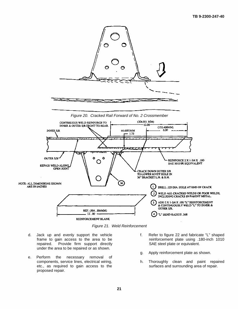
f. Drill 1/8-inch hole at end of crack and v-notch crack using portable grinding tool..
g. Apply weld to crack and grind flush.
h. Refer to figure 22 and fabricate "L"reinforcement plate using .180-inch SAEsteel plate or equivalent.
i. Apply reinforcement plate to both outerflanges of side rails, both top and bottom asshown.
j. Thoroughly clean repaired surfaces andsurrounding area of repair.
k. Prime and paint repair area andsurrounding surfaces as specified in TM-43-0139.
45. Defect. Cracked Outer Flange at Body MountBracket. Figure 21 illustrates a cracked side rail outerflange at the body mounting bracket forward of thenumber 2 crossmember. The crack occurs in the top orbottom flange as a result of an inadequate weld belowthe inner and outer side rail top or bottom joint.
a. Cleaning. Thoroughly clean vehicle frameof all oil, grease, dirt, and debris.
b. General Inspection. Perform generalvehicle frame inspection as specified inChapter 1.
c. Perform vehicle frame alignment inspectionas specified in Chapter 3.
20
TB 9-2300-247-40
Figure 20. Cracked Rail Forward of No. 2 Crossmember
Figure 21. Weld Reinforcement
d. Jack up and evenly support the vehicleframe to gain access to the area to berepaired. Provide firm support directlyunder the area to be repaired or as shown.
e. Perform the necessary removal ofcomponents, service lines, electrical wiring,etc., as required to gain access to theproposed repair.
f. Refer to figure 22 and fabricate "L" shapedreinforcement plate using .180-inch 1010SAE steel plate or equivalent.
g. Apply reinforcement plate as shown.
h. Thoroughly clean and paint repairedsurfaces and surrounding area of repair.
21
TB 9-2300-247-40
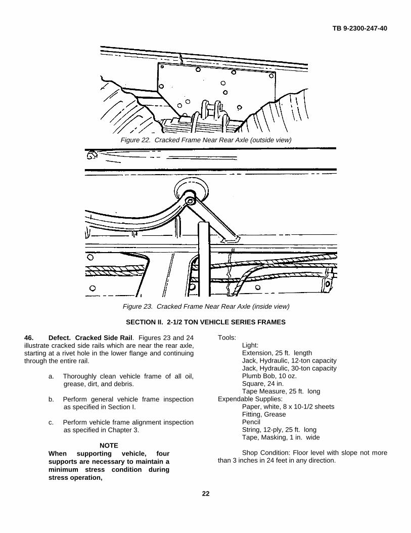
Figure 22. Cracked Frame Near Rear Axle (outside view)
Figure 23. Cracked Frame Near Rear Axle (inside view)
SECTION II. 2-1/2 TON VEHICLE SERIES FRAMES
46. Defect. Cracked Side Rail. Figures 23 and 24illustrate cracked side rails which are near the rear axle,starting at a rivet hole in the lower flange and continuingthrough the entire rail.
a. Thoroughly clean vehicle frame of all oil,grease, dirt, and debris.
b. Perform general vehicle frame inspectionas specified in Section I.
c. Perform vehicle frame alignment inspectionas specified in Chapter 3.
NOTEWhen supporting vehicle, foursupports are necessary to maintain aminimum stress condition duringstress operation,
Tools:Light:Extension, 25 ft. lengthJack, Hydraulic, 12-ton capacityJack, Hydraulic, 30-ton capacityPlumb Bob, 10 oz.Square, 24 in.Tape Measure, 25 ft. long
Expendable Supplies:Paper, white, 8 x 10⁻¹/2 sheetsFitting, GreasePencilString, 12-ply, 25 ft. longTape, Masking, 1 in. wide
Shop Condition: Floor level with slope not morethan 3 inches in 24 feet in any direction.
22
TB 9-2300-247-40
Floor surface must be flat within 1-inch in 24 feet. Floorclean of dirt, grease, oil, or debris.
Equipment Condition: Vehicle empty and vehicleundercarriage clean and completely free of mud,dirt, and debris.
d. Perform the necessary removal ofcomponents, service lines, electrical wiring,etc., as required to gain access to theproposed repair.
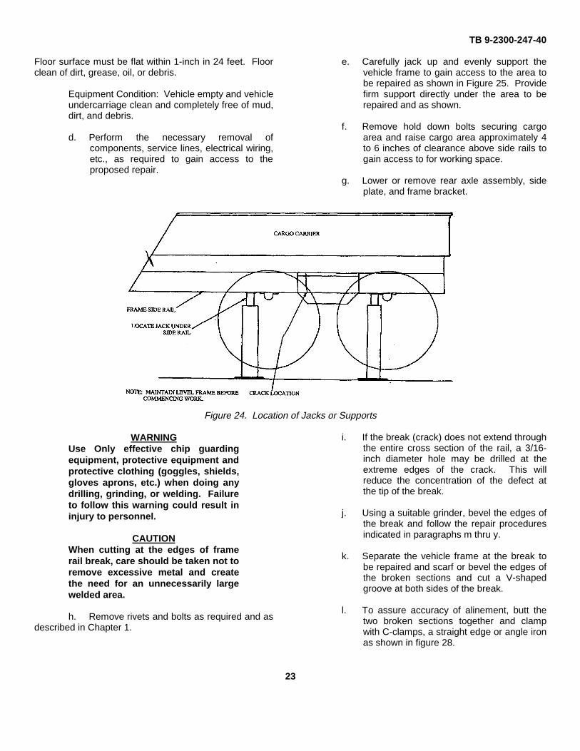
e. Carefully jack up and evenly support thevehicle frame to gain access to the area tobe repaired as shown in Figure 25. Providefirm support directly under the area to berepaired and as shown.
f. Remove hold down bolts securing cargoarea and raise cargo area approximately 4to 6 inches of clearance above side rails togain access to for working space.
g. Lower or remove rear axle assembly, sideplate, and frame bracket.
Figure 24. Location of Jacks or Supports
WARNINGUse Only effective chip guardingequipment, protective equipment andprotective clothing (goggles, shields,gloves aprons, etc.) when doing anydrilling, grinding, or welding. Failureto follow this warning could result ininjury to personnel.
CAUTIONWhen cutting at the edges of framerail break, care should be taken not toremove excessive metal and createthe need for an unnecessarily largewelded area.
h. Remove rivets and bolts as required and asdescribed in Chapter 1.
i. If the break (crack) does not extend throughthe entire cross section of the rail, a 3/16-inch diameter hole may be drilled at theextreme edges of the crack. This willreduce the concentration of the defect atthe tip of the break.
j. Using a suitable grinder, bevel the edges ofthe break and follow the repair proceduresindicated in paragraphs m thru y.
k. Separate the vehicle frame at the break tobe repaired and scarf or bevel the edges ofthe broken sections and cut a V-shapedgroove at both sides of the break.
l. To assure accuracy of alinement, butt thetwo broken sections together and clampwith C-clamps, a straight edge or angle ironas shown in figure 28.
23
TB 9-2300-247-40
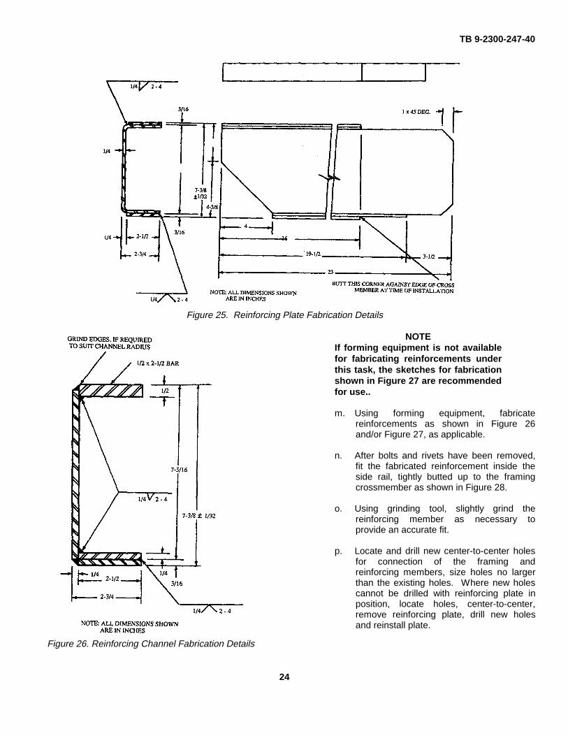
Figure 25. Reinforcing Plate Fabrication Details
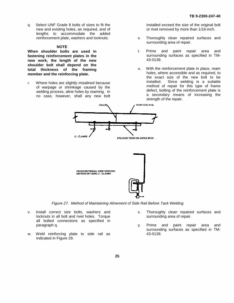
Figure 26. Reinforcing Channel Fabrication Details
NOTEIf forming equipment is not availablefor fabricating reinforcements underthis task, the sketches for fabricationshown in Figure 27 are recommendedfor use..
m. Using forming equipment, fabricatereinforcements as shown in Figure 26and/or Figure 27, as applicable.
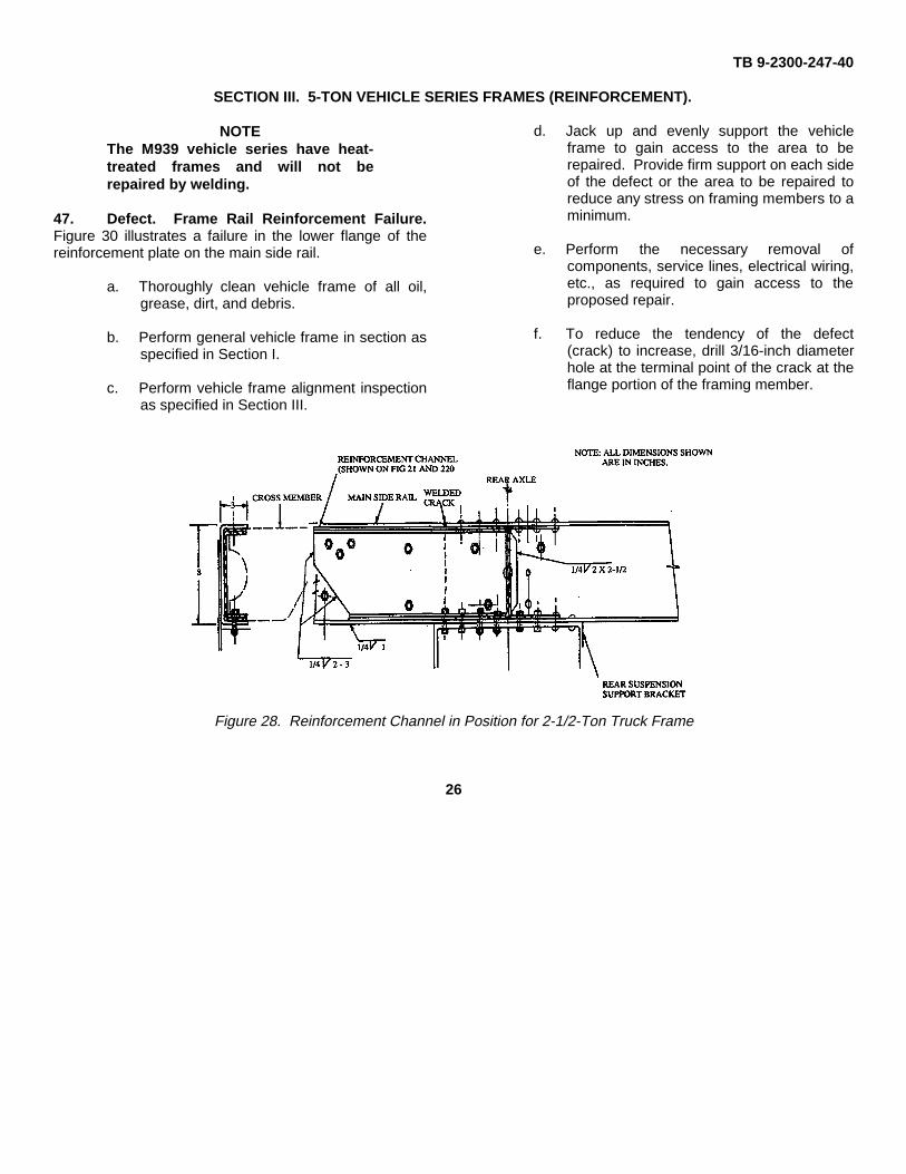
n. After bolts and rivets have been removed,fit the fabricated reinforcement inside theside rail, tightly butted up to the framingcrossmember as shown in Figure 28.
o. Using grinding tool, slightly grind thereinforcing member as necessary toprovide an accurate fit.
p. Locate and drill new center-to-center holesfor connection of the framing andreinforcing members, size holes no largerthan the existing holes. Where new holescannot be drilled with reinforcing plate inposition, locate holes, center-to-center,remove reinforcing plate, drill new holesand reinstall plate.
24
TB 9-2300-247-40
q. Select UNF Grade 8 bolts of sizes to fit thenew and existing holes, as required, and oflengths to accommodate the addedreinforcement plate, washers and locknuts.
NOTEWhen shoulder bolts are used infastening reinforcement plates in thenew work, the length of the newshoulder bolt shall depend on thetotal thickness of the framingmember and the reinforcing plate.
r. Where holes are slightly misalined becauseof warpage or shrinkage caused by thewelding process, aline holes by reaming. Inno case, however, shall any new bolt
installed exceed the size of the original boltor rivet removed by more than 1/16-inch.
s. Thoroughly clean repaired surfaces andsurrounding area of repair.
t. Prime and paint repair area andsurrounding surfaces as specified in TM-43-0139.
u. With the reinforcement plate in place, reamholes, where accessible and as required, tothe exact size of the new bolt to beinstalled. Since welding is a suitablemethod of repair for this type of framedefect, bolting of the reinforcement plate isa secondary means of increasing thestrength of the repair.
Figure 27. Method of Maintaining Alinement of Side Rail Before Tack Welding
v. Install correct size bolts, washers andlocknuts in all bolt and rivet holes. Torqueall bolted connections as specified inparagraph q.
w. Weld reinforcing plate to side rail asindicated in Figure 29.
x. Thoroughly clean repaired surfaces andsurrounding area of repair.
y. Prime and paint repair area andsurrounding surfaces as specified in TM-43-0139.
25
TB 9-2300-247-40
SECTION III. 5-TON VEHICLE SERIES FRAMES (REINFORCEMENT).
NOTEThe M939 vehicle series have heat-treated frames and will not berepaired by welding.
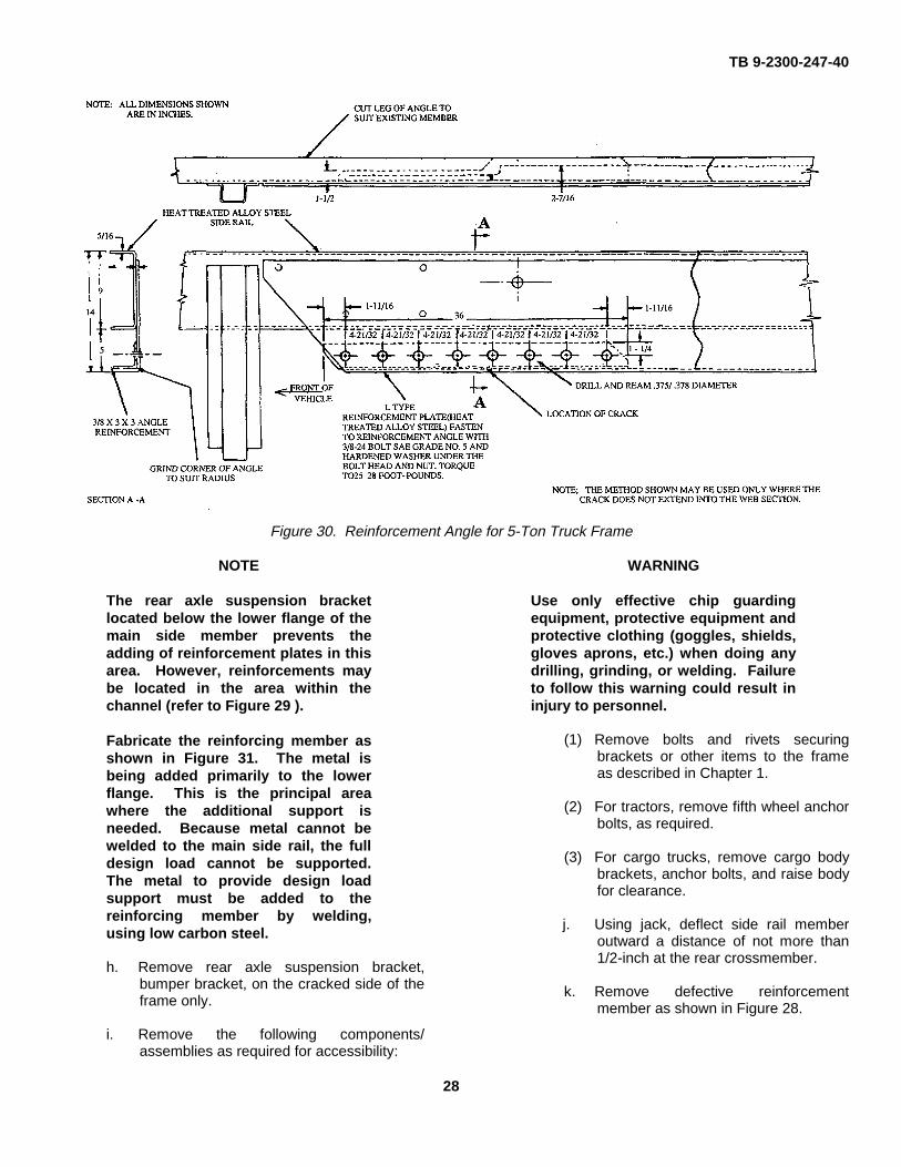
47. Defect. Frame Rail Reinforcement Failure.Figure 30 illustrates a failure in the lower flange of thereinforcement plate on the main side rail.
a. Thoroughly clean vehicle frame of all oil,grease, dirt, and debris.
b. Perform general vehicle frame in section asspecified in Section I.
c. Perform vehicle frame alignment inspectionas specified in Section III.
d. Jack up and evenly support the vehicleframe to gain access to the area to berepaired. Provide firm support on each sideof the defect or the area to be repaired toreduce any stress on framing members to aminimum.
e. Perform the necessary removal ofcomponents, service lines, electrical wiring,etc., as required to gain access to theproposed repair.
f. To reduce the tendency of the defect(crack) to increase, drill 3/16-inch diameterhole at the terminal point of the crack at theflange portion of the framing member.
Figure 28. Reinforcement Channel in Position for 2-1/2-Ton Truck Frame
26
TB 9-2300-247-40
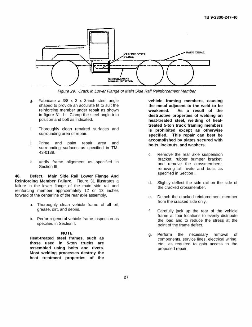
Figure 29. Crack in Lower Flange of Main Side Rail Reinforcement Member
g. Fabricate a 3/8 x 3 x 3-inch steel angleshaped to provide an accurate fit to suit thereinforcing member under repair as shownin figure 31 h. Clamp the steel angle intoposition and bolt as indicated.
i. Thoroughly clean repaired surfaces andsurrounding area of repair.
j. Prime and paint repair area andsurrounding surfaces as specified in TM-43-0139.
k. Verify frame alignment as specified inSection III.
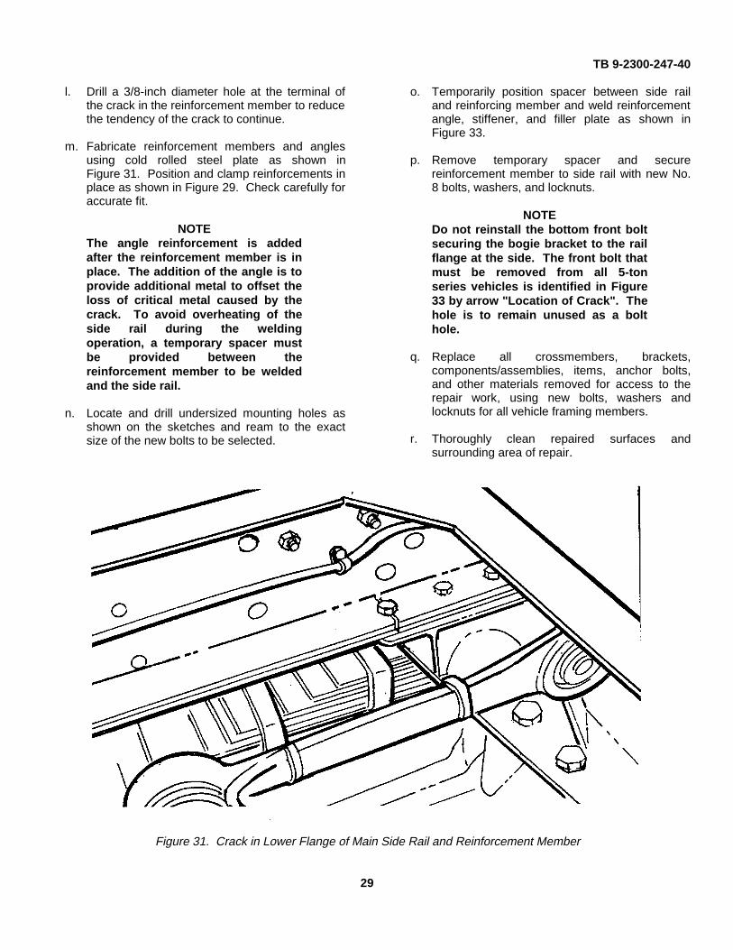
48. Defect. Main Side Rail Lower Flange AndReinforcing Member Failure. Figure 31 illustrates afailure in the lower flange of the main side rail andreinforcing member approximately 12 or 13 inchesforward of the centerline of the rear axle assembly.
a. Thoroughly clean vehicle frame of all oil,grease, dirt, and debris.
b. Perform general vehicle frame inspection asspecified in Section I.
NOTEHeat-treated steel frames, such asthose used in 5-ton trucks areassembled using bolts and rivets.Most welding processes destroy theheat treatment properties of the
vehicle framing members, causingthe metal adjacent to the weld to beweakened. As a result of thedestructive properties of welding onheat-treated steel, welding of heat-treated 5-ton truck framing membersis prohibited except as otherwisespecified. This repair can best beaccomplished by plates secured withbolts, locknuts, and washers.
c. Remove the rear axle suspensionbracket, rubber bumper bracket,and remove the crossmembers,removing all rivets and bolts asspecified in Section I.
d. Slightly deflect the side rail on the side ofthe cracked crossmember.
e. Detach the cracked reinforcement memberfrom the cracked side only.
f. Carefully jack up the rear of the vehicleframe at four locations to evenly distributethe load and to reduce the stress at thepoint of the frame defect.
g. Perform the necessary removal ofcomponents, service lines, electrical wiring,etc., as required to gain access to theproposed repair.
27
TB 9-2300-247-40
Figure 30. Reinforcement Angle for 5-Ton Truck Frame
NOTE
The rear axle suspension bracketlocated below the lower flange of themain side member prevents theadding of reinforcement plates in thisarea. However, reinforcements maybe located in the area within thechannel (refer to Figure 29 ).
Fabricate the reinforcing member asshown in Figure 31. The metal isbeing added primarily to the lowerflange. This is the principal areawhere the additional support isneeded. Because metal cannot bewelded to the main side rail, the fulldesign load cannot be supported.The metal to provide design loadsupport must be added to thereinforcing member by welding,using low carbon steel.
h. Remove rear axle suspension bracket,bumper bracket, on the cracked side of theframe only.
i. Remove the following components/assemblies as required for accessibility:
WARNING
Use only effective chip guardingequipment, protective equipment andprotective clothing (goggles, shields,gloves aprons, etc.) when doing anydrilling, grinding, or welding. Failureto follow this warning could result ininjury to personnel.
(1) Remove bolts and rivets securingbrackets or other items to the frameas described in Chapter 1.
(2) For tractors, remove fifth wheel anchorbolts, as required.
(3) For cargo trucks, remove cargo bodybrackets, anchor bolts, and raise bodyfor clearance.
j. Using jack, deflect side rail memberoutward a distance of not more than1/2-inch at the rear crossmember.
k. Remove defective reinforcementmember as shown in Figure 28.
28
TB 9-2300-247-40
l. Drill a 3/8-inch diameter hole at the terminal ofthe crack in the reinforcement member to reducethe tendency of the crack to continue.
m. Fabricate reinforcement members and anglesusing cold rolled steel plate as shown inFigure 31. Position and clamp reinforcements inplace as shown in Figure 29. Check carefully foraccurate fit.
NOTEThe angle reinforcement is addedafter the reinforcement member is inplace. The addition of the angle is toprovide additional metal to offset theloss of critical metal caused by thecrack. To avoid overheating of theside rail during the weldingoperation, a temporary spacer mustbe provided between thereinforcement member to be weldedand the side rail.
n. Locate and drill undersized mounting holes asshown on the sketches and ream to the exactsize of the new bolts to be selected.
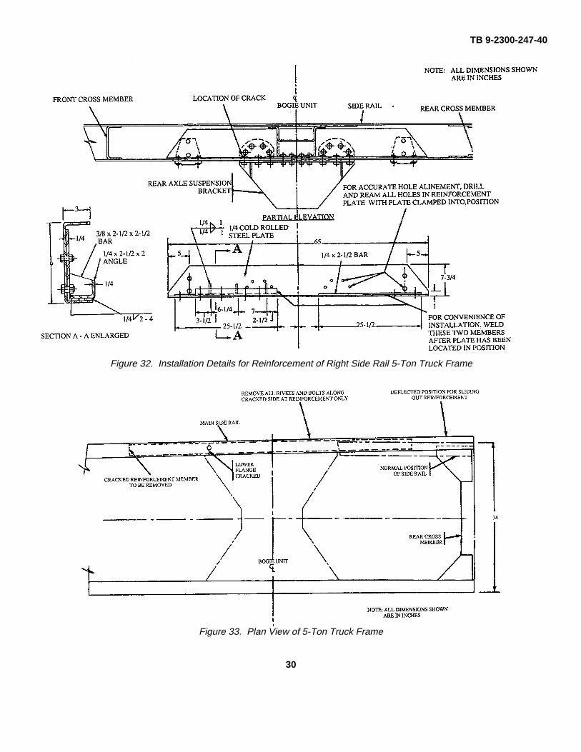
o. Temporarily position spacer between side railand reinforcing member and weld reinforcementangle, stiffener, and filler plate as shown inFigure 33.
p. Remove temporary spacer and securereinforcement member to side rail with new No.8 bolts, washers, and locknuts.
NOTEDo not reinstall the bottom front boltsecuring the bogie bracket to the railflange at the side. The front bolt thatmust be removed from all 5-tonseries vehicles is identified in Figure33 by arrow "Location of Crack". Thehole is to remain unused as a bolthole.
q. Replace all crossmembers, brackets,components/assemblies, items, anchor bolts,and other materials removed for access to therepair work, using new bolts, washers andlocknuts for all vehicle framing members.
r. Thoroughly clean repaired surfaces andsurrounding area of repair.
Figure 31. Crack in Lower Flange of Main Side Rail and Reinforcement Member
29
TB 9-2300-247-40
Figure 32. Installation Details for Reinforcement of Right Side Rail 5-Ton Truck Frame
Figure 33. Plan View of 5-Ton Truck Frame
30
TB 9-2300-247-40
s. Prime and paint repair area and surroundingsurfaces as specified in TM-43-0139.
t. Verify frame alinement as specified in Chapter 3.
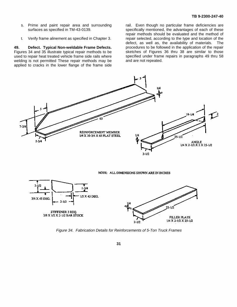
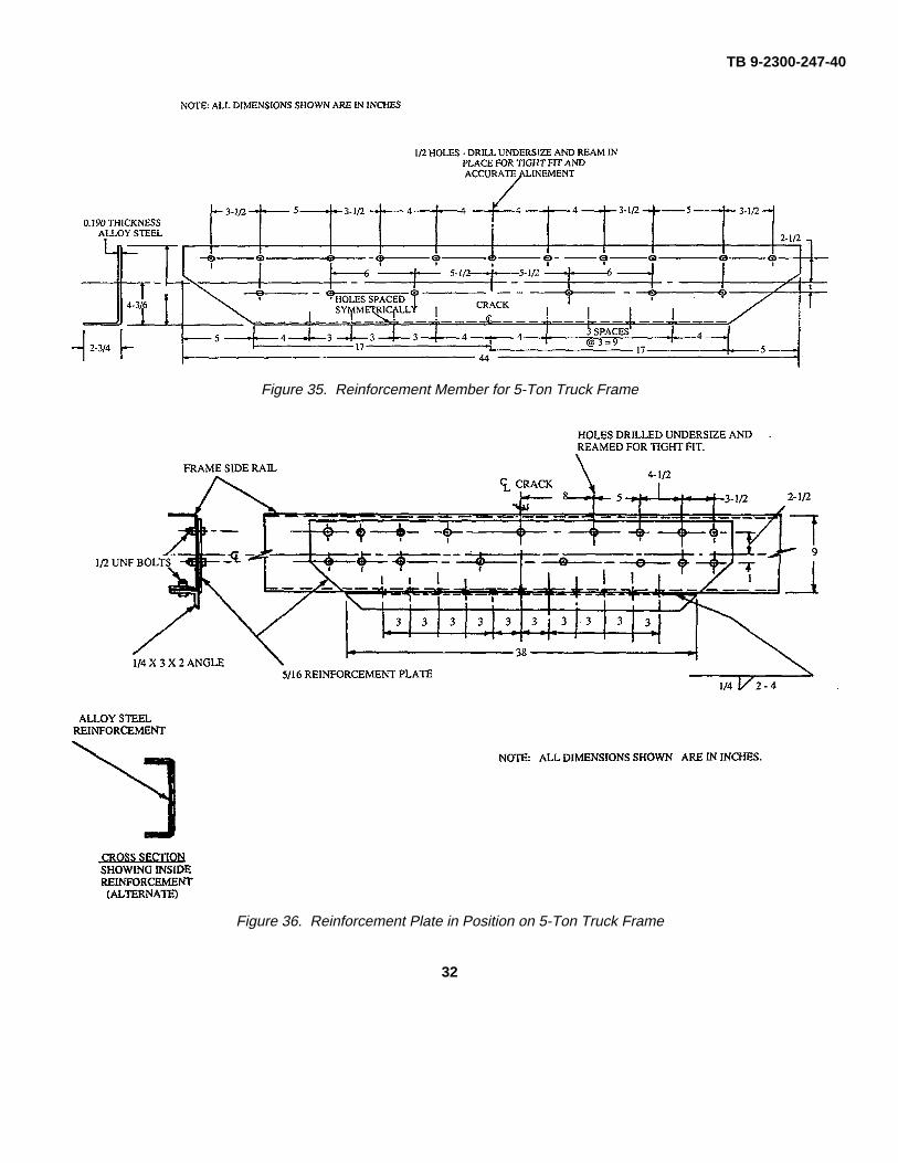
49. Defect. Typical Non-weldable Frame Defects.Figures 34 and 35 illustrate typical repair methods to beused to repair heat treated vehicle frame side rails wherewelding is not permitted These repair methods may beapplied to cracks in the lower flange of the frame side
rail. Even though no particular frame deficiencies arespecifically mentioned, the advantages of each of theserepair methods should be evaluated and the method ofrepair selected, according to the type and location of thedefect, as well as, the availability of materials. Theprocedures to be followed in the application of the repairsketches of Figures 36 thru 38 are similar to thosespecified under frame repairs in paragraphs 49 thru 58and are not repeated.
Figure 34. Fabrication Details for Reinforcements of 5-Ton Truck Frames
31
TB 9-2300-247-40
Figure 35. Reinforcement Member for 5-Ton Truck Frame
Figure 36. Reinforcement Plate in Position on 5-Ton Truck Frame
32
TB 9-2300-247-40
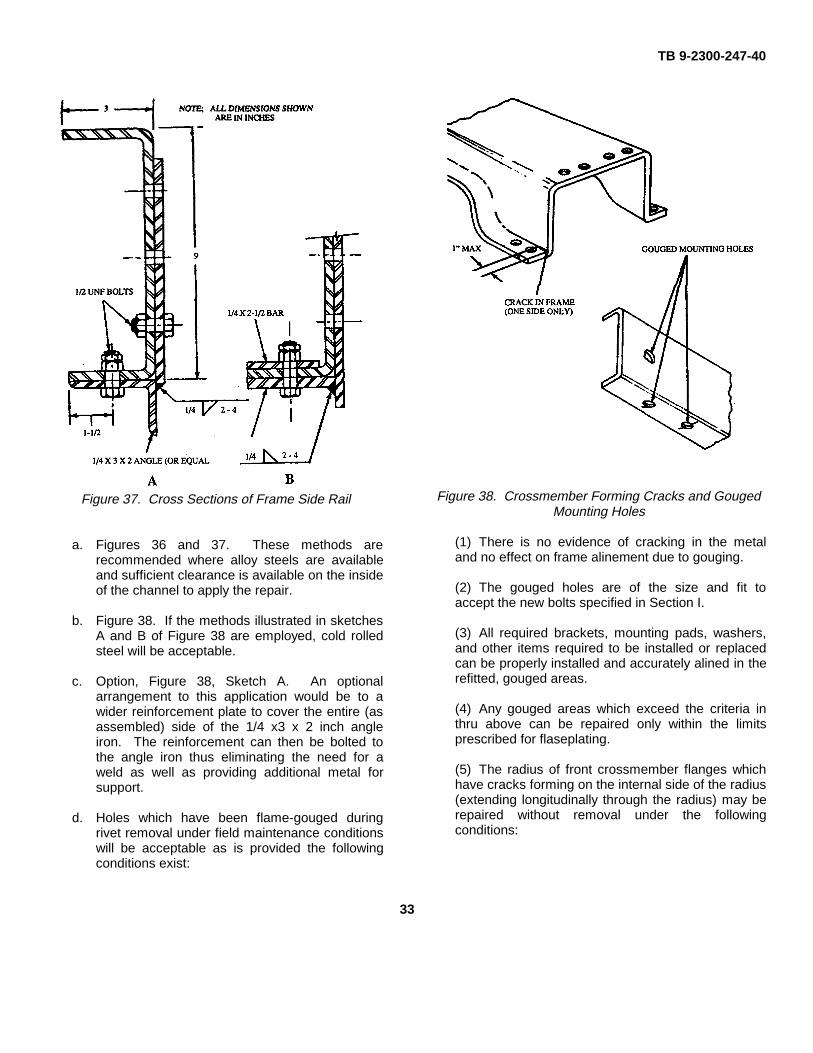
Figure 37. Cross Sections of Frame Side Rail
a. Figures 36 and 37. These methods arerecommended where alloy steels are availableand sufficient clearance is available on the insideof the channel to apply the repair.
b. Figure 38. If the methods illustrated in sketchesA and B of Figure 38 are employed, cold rolledsteel will be acceptable.
c. Option, Figure 38, Sketch A. An optionalarrangement to this application would be to awider reinforcement plate to cover the entire (asassembled) side of the 1/4 x3 x 2 inch angleiron. The reinforcement can then be bolted tothe angle iron thus eliminating the need for aweld as well as providing additional metal forsupport.
d. Holes which have been flame-gouged duringrivet removal under field maintenance conditionswill be acceptable as is provided the followingconditions exist:
Figure 38. Crossmember Forming Cracks and GougedMounting Holes
(1) There is no evidence of cracking in the metaland no effect on frame alinement due to gouging.
(2) The gouged holes are of the size and fit toaccept the new bolts specified in Section I.
(3) All required brackets, mounting pads, washers,and other items required to be installed or replacedcan be properly installed and accurately alined in therefitted, gouged areas.
(4) Any gouged areas which exceed the criteria inthru above can be repaired only within the limitsprescribed for flaseplating.
(5) The radius of front crossmember flanges whichhave cracks forming on the internal side of the radius(extending longitudinally through the radius) may berepaired without removal under the followingconditions:
33
TB 9-2300-247-40
(6) Forming cracks generate at sharp radius whenoriginally formed are detectable only on one side.
(7) Length of crack does not exceed 1-inch.Flanges with cracks exceeding 1-inch will be removed forwelding repair as shown in Figure 39.
SECTION IV. WELDING OF 5-TON VEHICLE FRAMES
NOTE
The M939 vehicle series have heat-treated frames and will not berepaired by welding.
50. General. 5-ton vehicle frames generallyexperience cracks at several common locations of boththe left and the right frame rails, at: (1) the trapezoidalplate, (2) bogie support bracket, intermediatecrossmembers, and the forward jounce brackets on thelower flange. Repairs to these areas may beaccomplished by special reinforcement plates, angles,and reinforcing doubler plates of various types. Thewelding repairs covered here will not include all possibledefects or frame conditions but relies on the experienceand ingenuity of repair personnel in the use of thisinformation.
51. Preliminary Procedures. Perform the followingpreliminary procedures:
a. Thoroughly clean vehicle frame o f all, oil,grease, dirt, paint, asphalt, and debris.
b. Perform general vehicle frame inspection asspecified in Chapter 1.
c. Perform vehicle frame alignment inspection asspecified in Chapter 3.
d. Remove all necessary components/assembliesas required for accessibility:
WARNING
Use only effective chip guardingequipment, protective equipment andprotective clothing (goggles, shields,gloves aprons, etc) when doing anydrilling, grinding, or welding. Failureto follow this warning could result ininjury to personnel.
e. Remove bolts and rivets securing securingbrackets or other items to the frame asdescribed in Chapter 1.
f. For tractors, remove fifth wheel, fifth wheelanchor bolts, dump bed, and hydraulic hoist, asrequired.
g. For cargo trucks, remove cargo body brackets,wooden sills, as applicable, remove anchorbolts, and raise body for clearance.
h. Remove all electrical harnesses, fuel andhydraulic lines, and related items as required foraccess to the area of repair. Take care topreserve the integrity of all components removedfor future installation.
i. Sketches. Prepare sketches to design specificrepair requirements as required and/or as shownin this section.
j. Where required, jack up and evenly support thevehicle frame to gain access to the area to berepaired. Provide firm support on each side ofthe defect or the area to be repaired to reduceany stress on framing members to a minimum.
k. Thoroughly clean all frame rails and supportingmembers of dirt, asphalt, paint, etc.
l. Once crack has been detected, measure crackwith crack limit gage (Figure 2) by placing gageon top of frame over the crack. Crack should notexceed 1-1/2-inches.
m. Using center punch, mark location of crack atthe extreme end of the crack.
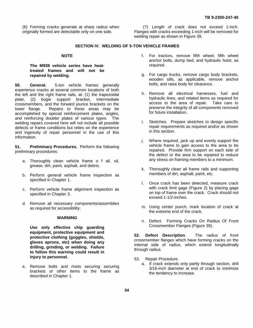
n. Defect. Forming Cracks On Radius Of FrontCrossmember Flanges (Figure 39).
52. Defect Description. The radius of frontcrossmember flanges which have forming cracks on theinternal side of radius, which extend longitudinallythrough radius.
53. Repair Procedure.a. If crack extends only partly through section, drill
3/16-inch diameter at end of crack to minimizethe tendency to increase.
34
TB 9-2300-247-40
b. Bevel edges of crack and weld to obtaincomplete penetration.
WARNING
Use only effective chip guardingequipment, protective equipment andprotective clothing (goggles, shields,gloves aprons, etc) when doing anydrilling, grinding, or welding. Failureto follow this warning could result ininjury to personnel.
c. Grind away excess metal of weld bead toeliminate bead acting as stress raiser.
d. Weld additional plates on each end ofcrossmember as described in paragraph 6.Plates shall be welded in area of highest density;approximately 6 inches measured in from eachend.
e. Stress relieve all welded areas for one hour byheat treating at 11250 F., plus or minus 25° F.
f. Thoroughly clean repaired surfaces andsurrounding area of repair.
g. Prime and paint repair area and surroundingsurfaces as specified in TM-43-0139.
Figure 39. (Added) Repair of Cracked Frame Rails
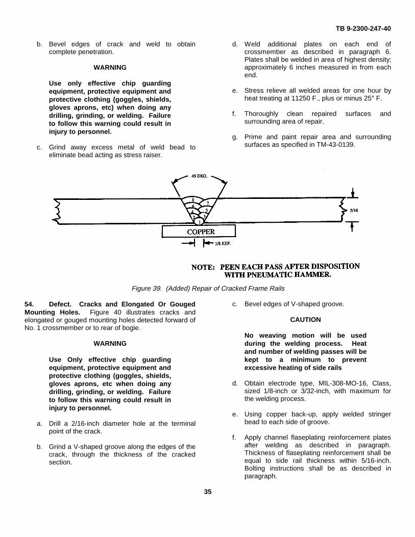
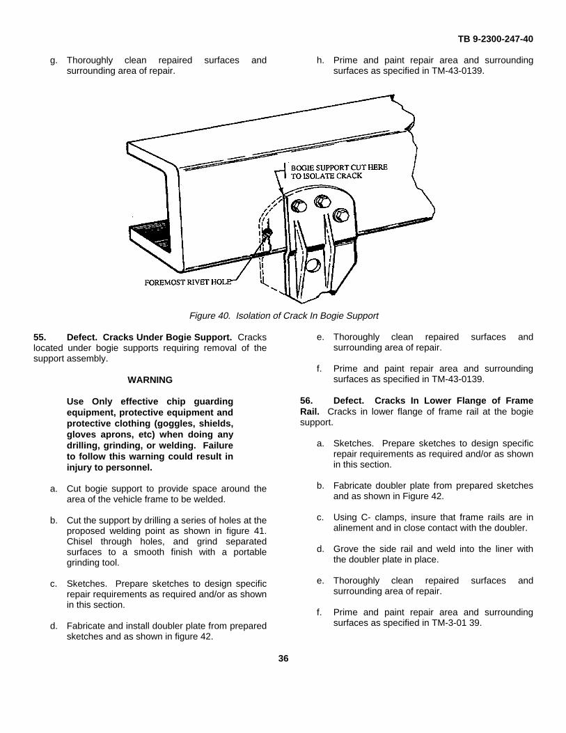
54. Defect. Cracks and Elongated Or GougedMounting Holes. Figure 40 illustrates cracks andelongated or gouged mounting holes detected forward ofNo. 1 crossmember or to rear of bogie.
WARNING
Use Only effective chip guardingequipment, protective equipment andprotective clothing (goggles, shields,gloves aprons, etc when doing anydrilling, grinding, or welding. Failureto follow this warning could result ininjury to personnel.
a. Drill a 2/16-inch diameter hole at the terminalpoint of the crack.
b. Grind a V-shaped groove along the edges of thecrack, through the thickness of the crackedsection.
c. Bevel edges of V-shaped groove.
CAUTION
No weaving motion will be usedduring the welding process. Heatand number of welding passes will bekept to a minimum to preventexcessive heating of side rails
d. Obtain electrode type, MIL-308-MO-16, Class,sized 1/8-inch or 3/32-inch, with maximum forthe welding process.
e. Using copper back-up, apply welded stringerbead to each side of groove.
f. Apply channel flaseplating reinforcement platesafter welding as described in paragraph.Thickness of flaseplating reinforcement shall beequal to side rail thickness within 5/16-inch.Bolting instructions shall be as described inparagraph.
35
TB 9-2300-247-40
g. Thoroughly clean repaired surfaces andsurrounding area of repair.
h. Prime and paint repair area and surroundingsurfaces as specified in TM-43-0139.
Figure 40. Isolation of Crack In Bogie Support
55. Defect. Cracks Under Bogie Support. Crackslocated under bogie supports requiring removal of thesupport assembly.
WARNING
Use Only effective chip guardingequipment, protective equipment andprotective clothing (goggles, shields,gloves aprons, etc) when doing anydrilling, grinding, or welding. Failureto follow this warning could result ininjury to personnel.
a. Cut bogie support to provide space around thearea of the vehicle frame to be welded.
b. Cut the support by drilling a series of holes at theproposed welding point as shown in figure 41.Chisel through holes, and grind separatedsurfaces to a smooth finish with a portablegrinding tool.
c. Sketches. Prepare sketches to design specificrepair requirements as required and/or as shownin this section.
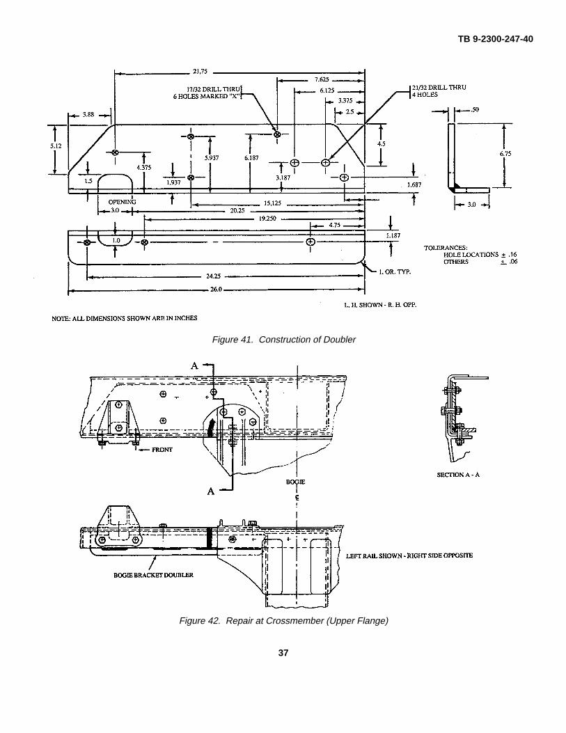
d. Fabricate and install doubler plate from preparedsketches and as shown in figure 42.
e. Thoroughly clean repaired surfaces andsurrounding area of repair.
f. Prime and paint repair area and surroundingsurfaces as specified in TM-43-0139.
56. Defect. Cracks In Lower Flange of FrameRail. Cracks in lower flange of frame rail at the bogiesupport.
a. Sketches. Prepare sketches to design specificrepair requirements as required and/or as shownin this section.
b. Fabricate doubler plate from prepared sketchesand as shown in Figure 42.
c. Using C- clamps, insure that frame rails are inalinement and in close contact with the doubler.
d. Grove the side rail and weld into the liner withthe doubler plate in place.
e. Thoroughly clean repaired surfaces andsurrounding area of repair.
f. Prime and paint repair area and surroundingsurfaces as specified in TM-3-01 39.
36
TB 9-2300-247-40
Figure 41. Construction of Doubler
Figure 42. Repair at Crossmember (Upper Flange)
37
TB 9-2300-247-40
57. Defect. Cracks in lower flange of frame railand liner at the bogie support.
a. Sketches. Prepare sketches to design specificrepair requirements as require and/or as shownin this section.
WARNINGUse Only effective chip guardingequipment, protective equipment andprotective clothing (goggles, shields,gloves aprons, etc) when doing anydrilling, grinding, or welding. Failureto follow this warning could result ininjury to personnel.
b. Cut outside edge 1/2-inch from the outer edgeand parallel to the bogie support rib.
c. Grind the entire edge to a rounded finish in orderto reduce crack sensitive conditions.
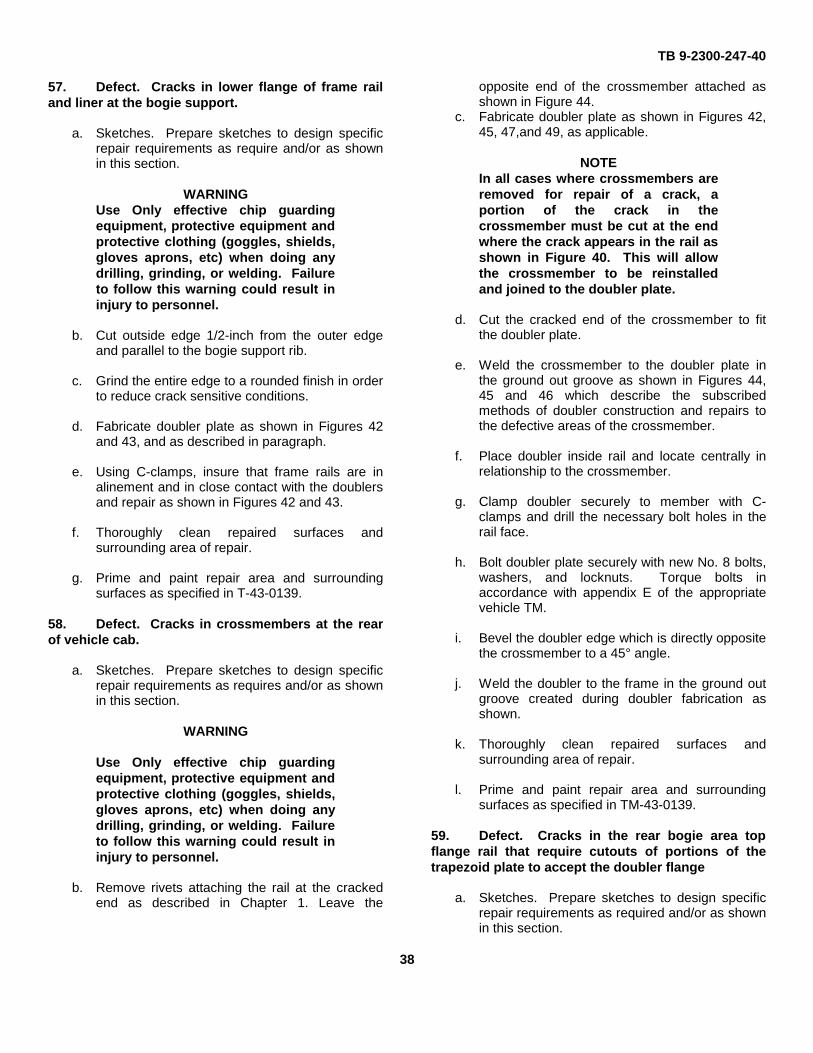
d. Fabricate doubler plate as shown in Figures 42and 43, and as described in paragraph.
e. Using C-clamps, insure that frame rails are inalinement and in close contact with the doublersand repair as shown in Figures 42 and 43.
f. Thoroughly clean repaired surfaces andsurrounding area of repair.
g. Prime and paint repair area and surroundingsurfaces as specified in T-43-0139.
58. Defect. Cracks in crossmembers at the rearof vehicle cab.
a. Sketches. Prepare sketches to design specificrepair requirements as requires and/or as shownin this section.
WARNING
Use Only effective chip guardingequipment, protective equipment andprotective clothing (goggles, shields,gloves aprons, etc) when doing anydrilling, grinding, or welding. Failureto follow this warning could result ininjury to personnel.
b. Remove rivets attaching the rail at the crackedend as described in Chapter 1. Leave the
opposite end of the crossmember attached asshown in Figure 44.
c. Fabricate doubler plate as shown in Figures 42,45, 47,and 49, as applicable.
NOTEIn all cases where crossmembers areremoved for repair of a crack, aportion of the crack in thecrossmember must be cut at the endwhere the crack appears in the rail asshown in Figure 40. This will allowthe crossmember to be reinstalledand joined to the doubler plate.
d. Cut the cracked end of the crossmember to fitthe doubler plate.
e. Weld the crossmember to the doubler plate inthe ground out groove as shown in Figures 44,45 and 46 which describe the subscribedmethods of doubler construction and repairs tothe defective areas of the crossmember.
f. Place doubler inside rail and locate centrally inrelationship to the crossmember.
g. Clamp doubler securely to member with C-clamps and drill the necessary bolt holes in therail face.
h. Bolt doubler plate securely with new No. 8 bolts,washers, and locknuts. Torque bolts inaccordance with appendix E of the appropriatevehicle TM.
i. Bevel the doubler edge which is directly oppositethe crossmember to a 45° angle.
j. Weld the doubler to the frame in the ground outgroove created during doubler fabrication asshown.
k. Thoroughly clean repaired surfaces andsurrounding area of repair.
l. Prime and paint repair area and surroundingsurfaces as specified in TM-43-0139.
59. Defect. Cracks in the rear bogie area topflange rail that require cutouts of portions of thetrapezoid plate to accept the doubler flange
a. Sketches. Prepare sketches to design specificrepair requirements as required and/or as shownin this section.
38
TB 9-2300-247-40
Figure 43. Crossmember Modification
Figure 44. Doubler at Crossmember
39
TB 9-2300-247-40
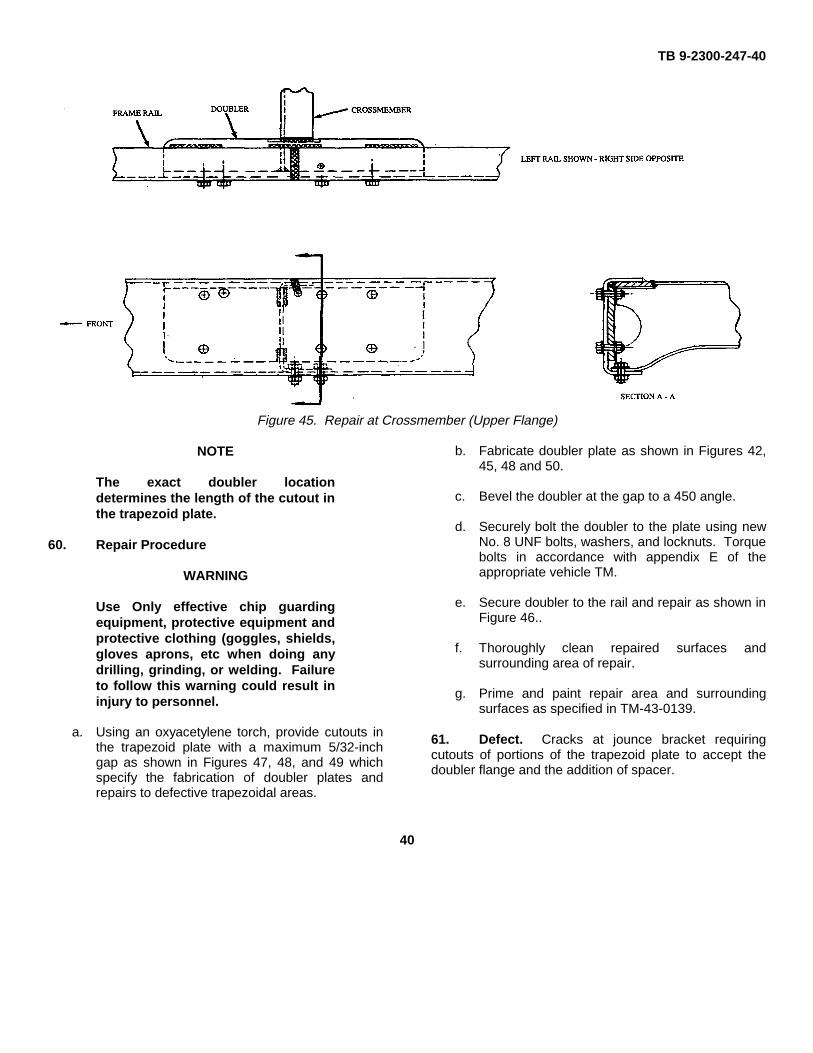
Figure 45. Repair at Crossmember (Upper Flange)
NOTE
The exact doubler locationdetermines the length of the cutout inthe trapezoid plate.
60. Repair Procedure
WARNING
Use Only effective chip guardingequipment, protective equipment andprotective clothing (goggles, shields,gloves aprons, etc when doing anydrilling, grinding, or welding. Failureto follow this warning could result ininjury to personnel.
a. Using an oxyacetylene torch, provide cutouts inthe trapezoid plate with a maximum 5/32-inchgap as shown in Figures 47, 48, and 49 whichspecify the fabrication of doubler plates andrepairs to defective trapezoidal areas.
b. Fabricate doubler plate as shown in Figures 42,45, 48 and 50.
c. Bevel the doubler at the gap to a 450 angle.
d. Securely bolt the doubler to the plate using newNo. 8 UNF bolts, washers, and locknuts. Torquebolts in accordance with appendix E of theappropriate vehicle TM.
e. Secure doubler to the rail and repair as shown inFigure 46..
f. Thoroughly clean repaired surfaces andsurrounding area of repair.
g. Prime and paint repair area and surroundingsurfaces as specified in TM-43-0139.
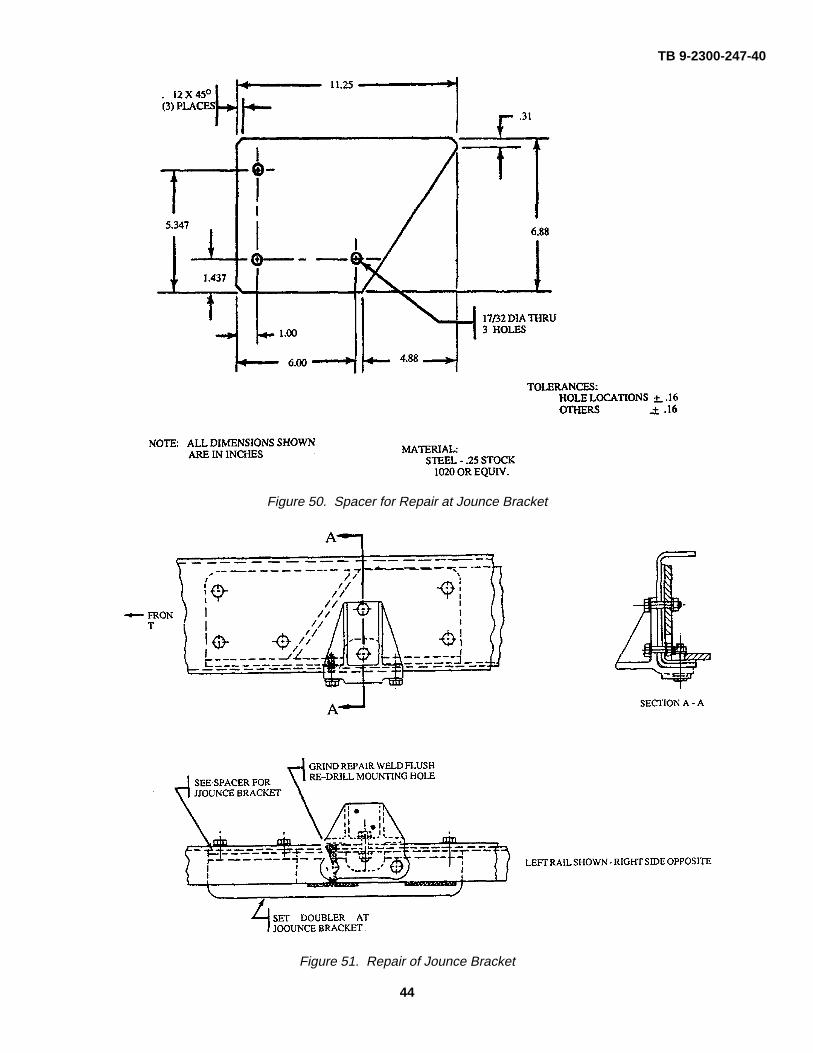
61. Defect. Cracks at jounce bracket requiringcutouts of portions of the trapezoid plate to accept thedoubler flange and the addition of spacer.
40
TB 9-2300-247-40
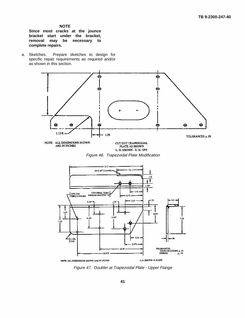
NOTESince most cracks at the jouncebracket start under the bracket,removal may be necessary tocomplete repairs.
a. Sketches. Prepare sketches to design forspecific repair requirements as required and/oras shown in this section.
Figure 46. Trapezoidal Plate Modification
Figure 47. Doubler at Trapezoidal Plate - Upper Flange
41
TB 9-2300-247-40
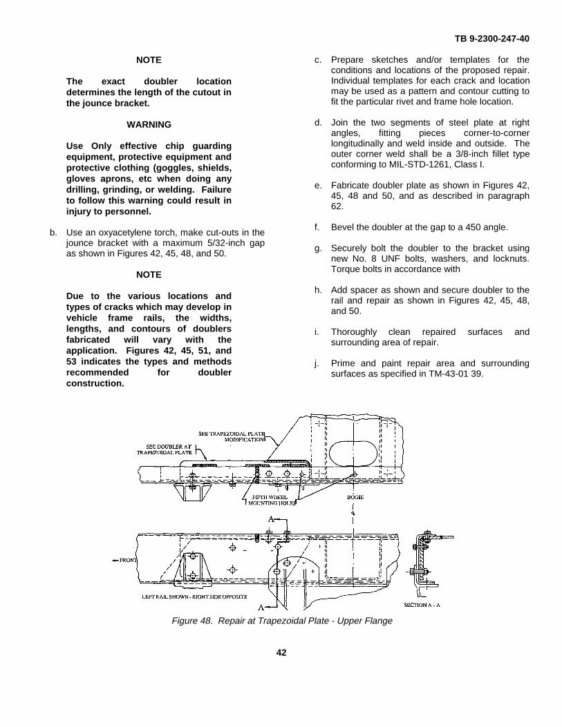
NOTE
The exact doubler locationdetermines the length of the cutout inthe jounce bracket.
WARNING
Use Only effective chip guardingequipment, protective equipment andprotective clothing (goggles, shields,gloves aprons, etc when doing anydrilling, grinding, or welding. Failureto follow this warning could result ininjury to personnel.
b. Use an oxyacetylene torch, make cut-outs in thejounce bracket with a maximum 5/32-inch gapas shown in Figures 42, 45, 48, and 50.
NOTE
Due to the various locations andtypes of cracks which may develop invehicle frame rails, the widths,lengths, and contours of doublersfabricated will vary with theapplication. Figures 42, 45, 51, and53 indicates the types and methodsrecommended for doublerconstruction.
c. Prepare sketches and/or templates for theconditions and locations of the proposed repair.Individual templates for each crack and locationmay be used as a pattern and contour cutting tofit the particular rivet and frame hole location.
d. Join the two segments of steel plate at rightangles, fitting pieces corner-to-cornerlongitudinally and weld inside and outside. Theouter corner weld shall be a 3/8-inch fillet typeconforming to MIL-STD-1261, Class I.
e. Fabricate doubler plate as shown in Figures 42,45, 48 and 50, and as described in paragraph62.
f. Bevel the doubler at the gap to a 450 angle.
g. Securely bolt the doubler to the bracket usingnew No. 8 UNF bolts, washers, and locknuts.Torque bolts in accordance with
h. Add spacer as shown and secure doubler to therail and repair as shown in Figures 42, 45, 48,and 50.
i. Thoroughly clean repaired surfaces andsurrounding area of repair.
j. Prime and paint repair area and surroundingsurfaces as specified in TM-43-01 39.
Figure 48. Repair at Trapezoidal Plate - Upper Flange
42
TB 9-2300-247-40
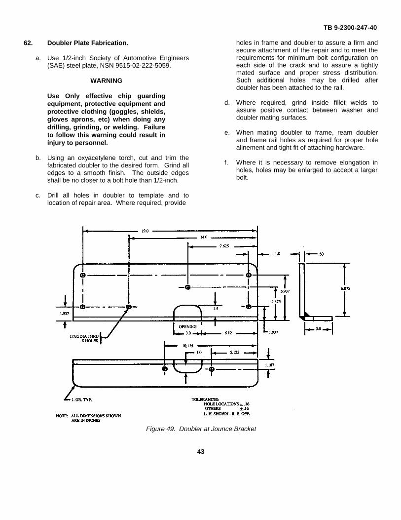
62. Doubler Plate Fabrication.
a. Use 1/2-inch Society of Automotive Engineers(SAE) steel plate, NSN 9515-02-222-5059.
WARNING
Use Only effective chip guardingequipment, protective equipment andprotective clothing (goggles, shields,gloves aprons, etc) when doing anydrilling, grinding, or welding. Failureto follow this warning could result ininjury to personnel.
b. Using an oxyacetylene torch, cut and trim thefabricated doubler to the desired form. Grind alledges to a smooth finish. The outside edgesshall be no closer to a bolt hole than 1/2-inch.
c. Drill all holes in doubler to template and tolocation of repair area. Where required, provide
holes in frame and doubler to assure a firm andsecure attachment of the repair and to meet therequirements for minimum bolt configuration oneach side of the crack and to assure a tightlymated surface and proper stress distribution.Such additional holes may be drilled afterdoubler has been attached to the rail.
d. Where required, grind inside fillet welds toassure positive contact between washer anddoubler mating surfaces.
e. When mating doubler to frame, ream doublerand frame rail holes as required for proper holealinement and tight fit of attaching hardware.
f. Where it is necessary to remove elongation inholes, holes may be enlarged to accept a largerbolt.
Figure 49. Doubler at Jounce Bracket
43
TB 9-2300-247-40
Figure 50. Spacer for Repair at Jounce Bracket
Figure 51. Repair of Jounce Bracket
44
TB 9-2300-247-40
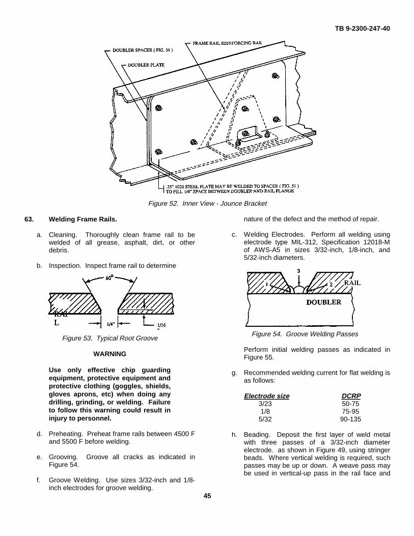
Figure 52. Inner View - Jounce Bracket
63. Welding Frame Rails.
a. Cleaning. Thoroughly clean frame rail to bewelded of all grease, asphalt, dirt, or otherdebris.
b. Inspection. Inspect frame rail to determine
Figure 53. Typical Root Groove
WARNING
Use only effective chip guardingequipment, protective equipment andprotective clothing (goggles, shields,gloves aprons, etc) when doing anydrilling, grinding, or welding. Failureto follow this warning could result ininjury to personnel.
d. Preheating. Preheat frame rails between 4500 Fand 5500 F before welding.
e. Grooving. Groove all cracks as indicated inFigure 54.
f. Groove Welding. Use sizes 3/32-inch and 1/8-inch electrodes for groove welding.
nature of the defect and the method of repair.
c. Welding Electrodes. Perform all welding usingelectrode type MIL-312, Specification 12018-Mof AWS-A5 in sizes 3/32-inch, 1/8-inch, and5/32-inch diameters.
Figure 54. Groove Welding Passes
Perform initial welding passes as indicated inFigure 55.
g. Recommended welding current for flat welding isas follows:
Electrode size DCRP3/23 50-751/8 75-955/32 90-135
h. Beading. Deposit the first layer of weld metalwith three passes of a 3/32-inch diameterelectrode. as shown in Figure 49, using stringerbeads. Where vertical welding is required, suchpasses may be up or down. A weave pass maybe used in vertical-up pass in the rail face and
45
TB 9-2300-247-40
radius part of the rail. Weld the remainder of thejoint with 1/8-inch diameter electrodes.
i. Flat, Vertical and Overhead Welding. Use onlystringer beads in the flange portion of the rail forflat and overhead welding. In welding thegroove, the doubler and/or liner is welded intothe joint. The recommended welding currentsfor flat welding are as follows:
(1) Use only stringer beads in the flange portion ofthe rail.
(2) For other positions of welding, such as vertical oroverhead, adjust welding currents to suit theconditions. Use lowest currents possible to obtainsound weld deposits.
j. Crown Welds. Completed welds shall have acrown deposit rising above the surface of the railto a maximum of 3/16-inch and not less than1/8-inch. There shall be no undercutting alongthe edge of weld deposits.
WARNING
Use only effective chip guardingequipment, protective equipment andprotective clothing (goggles, shields,gloves aprons, etc) when doing anydrilling, grinding, or welding. Failureto follow this warning could result ininjury to personnel.
k. Grinding. Remove by grinding all excess metaland/or weld globules in either the overhead orvertical position before proceeding with furtherwelding. All weld reinforcements shall be groundsmooth.
l. Slag Removal. Remove slag by chipping andwire brushing after each pass. Where C-clampsare used, they will not be removed until weldshave been inspected and found acceptable.
m. Heat Control. Heat control shall be maintainedthroughout the welding process. If temperaturesreach 750° F within 1-inch in any direction fromthe weld, halt the welding process, cover thearea affected with nylon felt cloth, and protectthe area from cold drafts for controlled cooling ofthe metal.
46
TB 9-2300-247-40
By Order of the Secretary of the Army:CARL E. VUONO
General, United States ArmyChief of Staff
Official:
PATRICIA P. HICKERSONColonel, United States Army
The Adjutant General
Distribution:To be distributed in accordance with DA Form 1238-E, block 0900, Direct and General Support maintenance
requirements for TB 9-2300-247-40.
*U.S. GOVERNMENT PRINTING OFFICE: 1993 - 342-421/63452
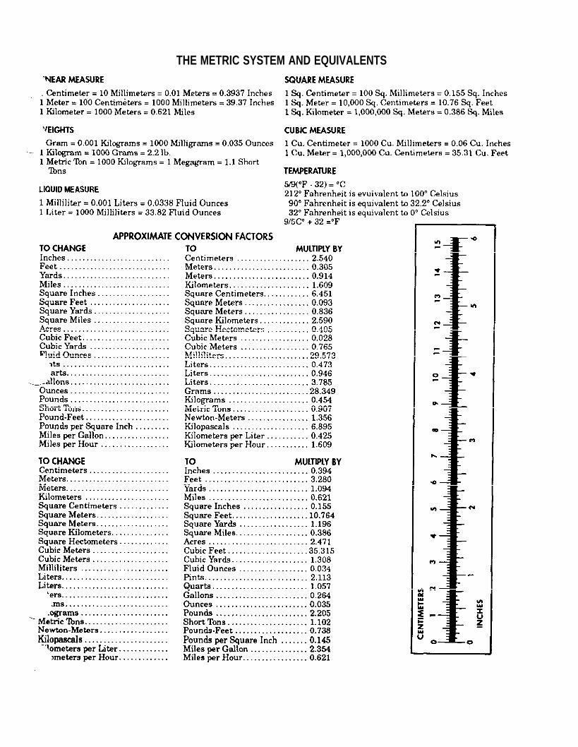
THE METRIC SYSTEM AND EQUIVALENTS

PIN: 013137-000