Embed Size (px)
Citation preview

7/21/2019 BC 2300 Service
http://slidepdf.com/reader/full/bc-2300-service 1/88
BC-2300
Hematology Analyzer
Service Manual

7/21/2019 BC 2300 Service
http://slidepdf.com/reader/full/bc-2300-service 2/88

7/21/2019 BC 2300 Service
http://slidepdf.com/reader/full/bc-2300-service 3/88
1
Copyright
2006 Shenzhen Mindray Bio-medical Electronics Co., Ltd. All rights Reserved.
For this Service Manual, the issued Date is 2006-3 (Version: 1.0).
Intellectual Property Statement
SHENZHEN MINDRAY BIO-MEDICAL ELECTRONICS CO., LTD. (hereinafter called
Mindray) owns the intellectual property rights to this Mindray product and this manual. This
manual may refer to information protected by copyrights or patents and does not convey any
license under the patent rights of Mindray, nor the rights of others. Mindray does not assume
any liability arising out of any infringements of patents or other rights of third parties.
Mindray intends to maintain the contents of this manual as confidential information.
Disclosure of the information in this manual in any manner whatsoever without the written
permission of Mindray is strictly forbidden.
Release, amendment, reproduction, distribution, rent, adaption and translation of this
manual in any manner whatsoever without the written permission of Mindray is strictly
forbidden.
, are the registered trademarks or trademarks owned by Mindray in China
and other countries. All other trademarks that appear in this manual are used only for
editorial purposes without the intention of improperly using them. They are the property of
their respective owners.
Responsibility on the Manufacturer Party
Contents of this manual are subject to changes without prior notice.
All information contained in this manual is believed to be correct. Mindray shall not be liable
for errors contained herein nor for incidental or consequential damages in connection with the
furnishing, performance, or use of this manual.
Mindray is responsible for safety, reliability and performance of this product only in the
condition that:
n all installation operations, expansions, changes, modifications and repairs of this productare conducted by Mindray authorized personnel;

7/21/2019 BC 2300 Service
http://slidepdf.com/reader/full/bc-2300-service 4/88
Table of Contents
2
n the electrical installation of the relevant room complies with the applicable national and
local requirements;
n the product is used in accordance with the instructions for use.
Upon request, Mindray may provide, with compensation, necessary circuit diagrams,
calibration illustration list and other information to help qualified technician to maintain and
repair some parts, which Mindray may define as user serviceable.
l This equipment is not intended for family usage.
l This equipment must be operated by skilled/trained medical
professionals.
l It is important for the hospital or organization that employs this equipment
to carry out a reasonable service/maintenance plan. Neglect of this may
result in machine breakdown or injury of human health.

7/21/2019 BC 2300 Service
http://slidepdf.com/reader/full/bc-2300-service 5/88
Table of Contents
3
Warranty
THIS WARRANTY IS EXCLUSIVE AND IS IN LIEU OF ALL OTHER WARRANTIES,
EXPRESSED OR IMPLIED, INCLUDING WARRANTIES OF MERCHANTABILITY OR
FITNESS FOR ANY PARTICULAR PURPOSE.
Exemptions
Mindray's obligation or liability under this warranty does not include any transportation or
other charges or liability for direct, indirect or consequential damages or delay resulting from
the improper use or application of the product or the use of parts or accessories not approved
by Mindray or repairs by people other than Mindray authorized personnel.
This warranty shall not extend to:
n any Mindray product which has been subjected to misuse, negligence or accident;
n any Mindray product from which Mindray's original serial number tag or product
identification markings have been altered or removed;
n any product of any other manufacturer.
Safety, Reliability and Performance
Mindray is not responsible for the effects on safety, reliability and performance of the
BC-2300 Hematology Analyzer if:
n assembly operations, extensions, re-adjusts, modifications or repairs are carried out by
persons other than those authorized by Mindray.
n Personnel unauthorized by Mindray repairs or modifies the instrument.

7/21/2019 BC 2300 Service
http://slidepdf.com/reader/full/bc-2300-service 6/88
Table of Contents
4
Return Policy
Return Procedure
In the event that it becomes necessary to return a unit to Mindray, the following procedure
should be followed:
1. Obtain return authorization. Contact the Mindray Service Department and obtain a
Customer Service Authorization (Mindray) number. The Mindray number must appear on
the outside of the shipping container. Return shipments will not be accepted if the
Mindray number is not clearly visible. Please provide the model number, serial number,
and a brief description of the reason for return.
2. Freight policy. The customer is responsible for freight charges when equipment is
shipped to Mindray for service (this includes customs charges).
Company contact
Manufacture: Shenzhen Mindray Bio-Medical Electronics Co., Ltd.
Address: Mindray Building, Keji 12th Road South, Hi-tech Industrial Park,
Nanshan, Shenzhen, P.R.China,518057
Phone: +86 755 26582479 26582888
Fax: +86 755 26582500 26582501
EC-Representative: Shanghai International Holding Corp. GmbH(Europe)
Address: Eiffestrae 80 D-20537 Hamburg Germany
Phone: +49 40 2513175
Fax: +49 40 255726

7/21/2019 BC 2300 Service
http://slidepdf.com/reader/full/bc-2300-service 7/88
Table of Contents
5
Table of Contents
Copyright 1
Warranty...........................................................................................................3
Table of Contents...............................................................................................................5
1 Using This Manual..................................................................................... 1-1
1.1 Introduction .........................................................................................1-1
1.2 Who Should Read This Manual ...........................................................1-1
1.3 How to Find Information ......................................................................1-1
1.4 Conventions Used in This Manual .......................................................1-3
1.5 Special Terms Used in This Manual .....................................................1-4
1.6 Symbols..............................................................................................1-5
2 HARDWARE ............................................................................................... 2-1
2.1 Electronic unit .....................................................................................2-1
2.1.1 Position of Electronic Unit .........................................................2-1
2.1.2 Schematic of Electronic Unit .....................................................2-3
2.2 CPU Board..........................................................................................2-4
2.2.1 Schematic.................................................................................2-4
2.2.2 Basic Functions ........................................................................2-4
2.2.3 Power Supply ...........................................................................2-5
2.2.4 RTC..........................................................................................2-5
2.2.5 CPU and Peripheral Devices.....................................................2-6
2.2.6 Analog Inputs and Outputs........................................................2-8
2.2.7 Digital Inputs and Outputs .........................................................2-8
2.3 Drive Board.......................................................................................2-10
2.3.1 Basic Functions ......................................................................2-10
2.3.2 Basic Units..............................................................................2-10
2.3.3 Detectable Signal....................................................................2-13
2.4 Display Unit.......................................................................................2-14
2.4.1 Function of the LCD Adapter ...................................................2-14
2.4.2 Introduction of the LCD Adapter ..............................................2-14
2.5 Keypad Unit ......................................................................................2-15
2.5.1 Function of the Keypad Adapter ..............................................2-15
2.5.2 Architecture of the Adapter......................................................2-15
2.5.3 Detailed Description................................................................2-15
2.6 Analog Board ....................................................................................2-18
2.6.1 Analog Board and Functions for Each Module.........................2-18
2.6.2 Module Circuits.......................................................................2-19
2.6.3 Analog Board Pot and the Adjustment Method ........................2-21

7/21/2019 BC 2300 Service
http://slidepdf.com/reader/full/bc-2300-service 8/88
Table of Contents
6
2.6.4 Test Points..............................................................................2-21
3 Disassembling/Replacing Parts and Components................................ 3-1
3.1 System Structure.................................................................................3-1
3.1.1 User Interfaces .........................................................................3-1
3.2 Disassembling Main Unit.....................................................................3-2
3.2.1 Removing the Left/Right Board and Top Cover..........................3-2
3.2.2 Removing the Back Cover & Power Supply Assembly...............3-3
3.2.3 Removing the Front Panel Assembly.........................................3-3
3.2.4 Removing the LCD Assembly....................................................3-4
3.2.5 Removing the Keypad...............................................................3-4
3.2.6 Removing the LCD and the Converter Board.............................3-5
3.2.7 Removing the Power Supply Shielding Box...............................3-5
3.2.8 Removing the main Bords.........................................................3-6
3.2.9 Removing the Pump and Pump Assembly.................................3-6
3.2.10 Removing the Valves ................................................................3-7
3.2.11 Removing the Valve 6 ...............................................................3-7
3.2.12 Removing the Syringe Assembly...............................................3-8
3.2.13 Removing the Volumetric Unit ...................................................3-8
3.2.14 Removing the Vacuum Assembly ..............................................3-9
3.2.15 Removing the Recorder ............................................................3-9
3.2.16 Removing the Converter Assembly .........................................3-10
4 Fluidic System........................................................................................... 4-1
4.1 Fluidic System.....................................................................................4-1
4.2 Construction of Fluidic System ............................................................4-1
4.3 Composition of Fluidic System.............................................................4-1
4.4 Functional Modules.............................................................................4-1
4.4.1 Aspiration/Dispensing Module...................................................4-2
4.4.2 Counting Module.......................................................................4-3
4.4.3 Washing Module.......................................................................4-4
4.4.4 Hydraulic Module......................................................................4-5
4.4.5 Mixing Module ..........................................................................4-6
4.4.6 Waste Discharging Module........................................................4-6
4.5 Counting Timing..................................................................................4-7
4.5.1 Whole Blood Mode....................................................................4-7
4.5.2 Predilute Mode..........................................................................4-8
4.5.3 Volume Range of Blood Cells....................................................4-9
5 Software ..................................................................................................... 5-1
5.1 Executing of the Bootstrap Program ....................................................5-1
5.2 System Software Initialization..............................................................5-1
5.3 Password............................................................................................5-3
5.4 Software Upgrade ...............................................................................5-4
7/21/2019 BC 2300 Service
http://slidepdf.com/reader/full/bc-2300-service 9/88
Table of Contents
7
5.4.1 Upgrade Procedure...................................................................5-4
5.4.2 Notes and the Error Alarms.......................................................5-5
5.5 Setup ..................................................................................................5-5
6 Histograms and Pulse Graphs................................................................. 6-1
6.1 Histograms..........................................................................................6-1
6.2 Pulse Graphs ......................................................................................6-4
6.2.1 Normal Pulse Graphs................................................................6-4
6.2.2 Abnormal Pulse Graphs............................................................6-5
7 Troubleshooting........................................................................................ 7-1
7.1 Error Code ..........................................................................................7-3
7.2 Solutions.............................................................................................7-4
7.2.1 56V Error ..................................................................................7-4
8 List of Spare Parts..................................................................................... 8-1
9 8-2

7/21/2019 BC 2300 Service
http://slidepdf.com/reader/full/bc-2300-service 10/88
1-1
1 Using This Manual
Introduction
This chapter explains how to use your BC-2300 service manual, which provides the reference
information and procedures needed for servicing your BC-2300 analyzer. Read this manual
carefully before servicing your analyzer and service your analyzer strictly as instructed in this
manual.
This manual is to be used in conjunction with the BC-2300 analyzer operation manual and
does not contain information and procedures already covered in the operation manual.
l Be sure to service your analyzer strictly as instructed in this manual and the
operation manual.
Who Should Read This Manual
This service manual is written for people who
n have a thorough understanding of electronic and fluidic principles.
n have a thorough understanding of reagent systems.
n have a thorough understanding of quality control.
n have a thorough understanding of troubleshooting concepts.
n have an operator !s knowledge of the analyzer.
n have the ability to use basic mechanical tools and understand related terminology.
n have the ability to use a digital voltmeter (DVM) and an oscilloscope.
n have the ability to read electronic and fluidic schematics and understand related
terminology.
How to Find Information

7/21/2019 BC 2300 Service
http://slidepdf.com/reader/full/bc-2300-service 11/88
Using This Manual
1-2
This operation manual comprises 8 chapters and 2 appendices. Refer to the table below to
find the information you need.
If you want to
See
learn about the hardware and how to test the boards ofBC-2300
Chapter 2 Hardware
learn about the system structure and how to
disassemble/replace parts and components of BC-2300
Chapter 3
Disassembling/Replacing
Parts and Components
learn about how fluidic system functions Chapter 4 Fluidic System
learn about how passwords function and how to upgrade the
BC-2300 software
Chapter 5 Software
learn about the histograms and pulse graphs Chapter 6 Histograms and
Pulse Graphs
learn about how to troubleshoot your BC-2300 Chapter 7 Troubleshooting
learn about the main spare parts of BC-2300 Chapter 8 List of Spare Parts
learn about the schematic diagram of the fluidic system Appendix A Fluidic Diagram
learn about the correspondence between errors and error
codes of BC-2300
Appendix B Error Code
Description

7/21/2019 BC 2300 Service
http://slidepdf.com/reader/full/bc-2300-service 12/88
Using This Manual
1-3
Conventions Used in This Manual
This manual uses certain typographical conventions to clarify meaning in the text:
n All capital letters enclosed in [ ] indicate a key name (either on the built-in keypad or theexternal keyboard), such as [ENTER].
n All capital, bold and italic letters indicate a special operation defined in the following
section, such as SELECT .
n Bold letters included in " # indicate text you can find on the screen, such as "Prepare to
ship#.
n Bold letters indicate defined screen areas/fields, such as System Status area, or
chapter titles, such as Chapter 1 Using This Manual.
All illustrations in this manual are provided as examples only. They may not necessarily
reflect your analyzer setup or data displayed.

7/21/2019 BC 2300 Service
http://slidepdf.com/reader/full/bc-2300-service 13/88
Using This Manual
1-4
Special Terms Used in This Manual
When you read It means
CLICKto press the arrow keys ([$][%] [&][']) as needed to move the
cursor to a certain software button on screen and press
[ENTER].
ENTER
to press the arrow keys ([$][%] [&][']) as needed to move
cursor to the desired edit box and use the built-in keypad or
the external keyboard to enter the desired characters or digits.
Note that besides the numeric keys you may also use the
[PgUp] or [PgDn] keys to enter digits; or to scan the number
using the bar-code scanner.
DELETE
to press the arrow keys ([$][%] [&][']) as needed to move the
cursor to the character or digit to the left of the one you want to
delete and press [DEL]; or to press the arrow keys
([$][%][&][']) as needed to move the cursor to the character
or digit to the right of the one you want to delete and press
[BackSpace] on the external keyboard.
MODIFY to move the cursor to the character or digit you want to changeand re-enter the desired one using either the built-in keypad or
the external keyboard.
SELECT from ** !
pul l -down l ist
to press the arrow keys ([$][%] [&][']) as needed to move the
cursor to the desired edit box and press [ENTER] to display
the pull-down list and press [&] or ['] to move the cursor to the
desired item and press [ENTER] to select it.
SELECTto press the arrow keys ([$][%] [&][']) as needed to the
desired item and press [ENTER].
l This analyzer adopts a fixed decimal point. You can enter the digits without
bothering to look for the [.] on the external keyboard.

7/21/2019 BC 2300 Service
http://slidepdf.com/reader/full/bc-2300-service 14/88
Using This Manual
1-5
Symbols
You will find the following symbols in this manual.
When you see Then
read the statement below the symbol. The statement is
alerting you to an operating hazard that can cause
personnel injury.
read the statement below the symbol. The statement is
alerting you to a possibility of analyzer damage or unreliable
analysis results.
read the statement below the symbol. The statement is
alerting you to information that requires your attention.
read the statement below the symbol . The statement is
alerting you to a potentially biohazardous condition.
You may find the following symbols on the analyzer or the reagents.
When you see It means
EQUIPOTENTIALITY
CAUTION, CONSULT ACCOMPANYING
DOCUMENTS.
BIOLOGICAL RISK
HIGH VOLTAGE
IN VITRO DIAGNOSTIC
ALTERNATING CURRENT

7/21/2019 BC 2300 Service
http://slidepdf.com/reader/full/bc-2300-service 15/88
Using This Manual
1-6
USE BY
SERIAL NUMBER
DATE OF MANUFACTURE
TEMPERATURE LIMITATION
CONSULT INSTRUCTIONS FOR USE
THE DEVICE IS FULLY CONFORMANCE
WITH THE COUNCIL DIRECTIVE
CONCERNING IN VITRO DIAGNOSTIC
MEDICAL DEVICES 98/79/EC.
MANUFACTURER
AUTHORISED REPRESENTATIVE IN THE
EUROPEAN COMMUNITY
IRRITATING SUBSTANCE
THE FOLLOWING DEFINITION OF THE
WEEE LABEL APPLIES TO EU MEMBER
STATES ONLY: THE USE OF THIS SYMBOL
INDICATES THAT THIS PRODUCT SHOULD
NOT BE TREATED AS HOUSEHOLD
WASTE. BY ENSURING THAT THIS
PRODUCT IS DISPOSED OF CORRECTLY,
YOU WILL HELP PREVENT BRINGING
POTENTIAL NEGATIVE CONSEQUENCES
TO THE ENVIRONMENT AND HUMAN
HEALTH. FOR MORE DETAILED
INFORMATION WITH REGARD TO

7/21/2019 BC 2300 Service
http://slidepdf.com/reader/full/bc-2300-service 16/88
Using This Manual
1-7
RETURNING AND RECYCLING THIS
PRODUCT, PLEASE CONSULT THE
DISTRIBUTOR FROM WHOM YOU
PURCHASED THE PRODUCT.

7/21/2019 BC 2300 Service
http://slidepdf.com/reader/full/bc-2300-service 17/88
2-1
2 HARDWARE
Electronic unit
Position of Electronic Unit
Located inside the analyzer, the electronic unit comprises CPU board, analog board and
drive board, as shown in figure 2-1.
figure 2-1 inside back of the analyser
The boards are fixed directly by screws. The drive board is fixed with 6 M3 screws, while
both the CPU board and analog board are fixed with 4 M3 screws respectively. The drive
board is 2mm away from the CPU board and analog board, which are separated by about
27mm.
The volumetric unit is located above the vacuum chamber assembly, as shown in
figure 2-2.
The upper end of the metering tube is connected to the solenoid valve by a T-piece,
while the lower end to the vacuum chamber unit by a hose. The metering tube itself is
fixed on the volumetric unit by 2 brackets. Together with the metering tube, the pot on
the metering tube can be adjusted to ensure correct level signals.
Drive board
Analog board
CPU board
Power supply
unit

7/21/2019 BC 2300 Service
http://slidepdf.com/reader/full/bc-2300-service 18/88
HARDWARE
2-2
figure 2-2 Volumetric unit
Panels consist of main user interfaces, such as recorder unit (recorder drive board),
keypad, indicator board and screen unit (LCD, inverter and LCD adapter), as shown in
figure2-3.
figure 2-3 Panels disassembly view
Volumetric unit
Keypad
LCD
Recorder
Converter

7/21/2019 BC 2300 Service
http://slidepdf.com/reader/full/bc-2300-service 19/88
HARDWARE
2-3
Schematic of Electronic Unit
CPU board
Analog board
Power-drive board
Volumetric
board
SyringePhoto
coupler
H G B
I/OInterface
+12V
+30V
!12V
+5V
+12V
A C 1 0 0 ~ 2 4 0 V
P o w e r s u p pl y
B o a r d
pr e s s ur e
temperature
Valve/Pump
P o w e r
s wi t c h
D OM
Bath
Electrode
Recorder
Drive Board
Keypad
Backlight
Drive Board
LCDAdapter
Start
Key
Display
figure 2-4 Schematic of Electronic Unit

7/21/2019 BC 2300 Service
http://slidepdf.com/reader/full/bc-2300-service 20/88
HARDWARE
2-4
CPU Board
Schematic
figure 2-5 Schematic of the CPU board
The CPU, FPGA and Super I/O are the major components on the board. The CPU
carries out the instructions and functions as the core of the board. The FPGA functions
as the relay between the CPU and the Super IO. The Super I/O includes various
interfaces that can be accessed by the CPU through the FPGA. System memories are
SDRAMs. The DOM is a Disk-On-Module that stores the system software and test data.
The RTC is a real time clock. System configurations are stored in the EEPROM. The
VRAM is the memory for video display.
Basic Functions
To receive such analog signals as the WBC/RBC+PLT counts, HGB measurement,aperture voltage, vacuum/pressure signals, etc.
To monitor such system status as the +56V, +12V and -12V supplies of the analog
board, the +3.3V and +12V supplies of the CPU board itself and the temperature of the
whole analyzer.
To receive the keypad signal and control the keypad buzzer and LCD backlight.
To generate control signals to control the pump/valves, aperture zapping, HGB
LED, current source and digital pot.
To drive and turn on the LCD and adjust the contrast.
To drive the keyboard, printer and floppy drive.

7/21/2019 BC 2300 Service
http://slidepdf.com/reader/full/bc-2300-service 21/88
HARDWARE
2-5
Power Supply
The CPU board is powered by two independent external power supplies, a +5V
supply and a 12V supply. Two 5A fuses are respectively installed on the two power
entries. The +5V supply is converted a +3.3V supply to power the digital components
and the +3.3V supply is also further converted into a +1.5V supply to power the FPGA.
The +12V supply serves the CPU board only.
figure 2-6 Power distribution of the CPU board
RTC
figure 2-7 Arrangement of the CPU Clock

7/21/2019 BC 2300 Service
http://slidepdf.com/reader/full/bc-2300-service 22/88
HARDWARE
2-6
The X1, X4 and X2 are external crystal oscillators whose frequencies are 45MHz,
45MHz and 24MHz respectively. The clock output of the CPU, BCLKO, is main clock
signal of the CPU board.
CPU and Peripheral Devices
figure 2-8 CPU and peripheral devices
1. CPU
n The CPU is MOTOROLA MCF5307 (external frequency 45MHz; operation
frequency 90MHz; processing speed as high as 75MIPS).
n The MCF5307 features a 32-bit data bus and a 32-bit address bus. The board
uses a 24-bit addressing mode, reserving the most-significant 8 bits as the
general purpose I/Os for the FPGA.
n The MCF5307 can be tuned through the BDM port (J18 of the CPU board).
n The CPU board utilizes the built-in I2C and UART controllers of the MCF5307
to use the EEPROM and RTC as expanded serials ports.
n The CPU boards utilizes the built-in DRAM controller of the MCF5307 to use
the 2(8M SDRAM as the expanded memory.
2. WDT
The Watch-Dog-Timer (WDT) is TI TPS3828. It monitors the running of the
software. The CPU must send a feedback to the WDT every 1.6s, otherwise the WDT
will force the CPU to restart.

7/21/2019 BC 2300 Service
http://slidepdf.com/reader/full/bc-2300-service 23/88
HARDWARE
2-7
figure 2-9 WDT
3. FLASH
The FLASH is TE28F160(2M bytes) . The boot program is stored in the FLASH, so
the FLASH is also called the BootROM. Every time the system is powered on, the CPU
first executes the boot program that initializes the system and loads the controlsoftware from the DOM. The FLASH also contains such information as the FPGA
configuration, FPGA version and LCD contrast.
4. SDRAM
The system memory consists of two 8M-byte memories.
5. DOM
The CPU board uses a 32M DOM that is powered by a 3.3V supply (the DOM can
also be supplied by 5V supply). The DOM is only operational after the FPGA is
configured.
6. RTC
The CPU board uses a real time clock (RTC) to record the time. The RTC is
connected to the I2C bus of the CPU board and synchronized by a 32.768KHz crystal
oscillator. When the analyzer is powered on, the RTC is powered by the CPU board;
when the analyzer is powered off, it is powered by the built-in battery.
7. EEPROM
The CPU board uses an 8K byte EEPROM to store such information as systemconfigurations and settings. It is connected to the I2C bus of the CPU and can be
written by CPU on-line.
8. LEDs
When D1 is on, it means +3.3V is functioning properly. When D9 is on, it means
+12.8V is functioning properly. When D5 is on, it means the system is reading or
writing the DOM. When D7 is on, it means the FPGA has been configured and is
functioning properly. When D20 is on, it means the FPGA is restarting; The D11"D18
indicate the system status as defined by the software.

7/21/2019 BC 2300 Service
http://slidepdf.com/reader/full/bc-2300-service 24/88
HARDWARE
2-8
Analog Inputs and Outputs
1. Signals of Blood Cell Counts
The CPU board has three A/D converters, U10 (AD7928), U11(AD7908) and U14
(AD7908). Both the AD7928 and AD7908 feature 8-channel and 1MSPS, only the
former is 12-bit converter and the latter 8-bit. The U10 is actually installed and powered
by a 2.5V supply, while the U11 and U14 are reserved. The sampling speed is set to
500KSPS.
2. Signals of System Monitoring
The Super I/O monitors such system status as the +56V, +12V and -12V supplies
of the analog board, the +3.3V and +12V supplies of the CPU board itself and the
temperature of the whole analyzer.
3. Signals of LCD ContrastThe Super I/O generates PWM signals that are then integrated to output a 0~2.5V
analog signal to control the LCD contrast. The user can adjust the contrast through the
software interface.
Digital Inputs and Outputs
1. Serial Port
The analyzer has 6 serial ports, which are illustrated in Figure 2-10.
figure 2-10 Serial Ports
The CPU incorporates 2 UART controllers (3.3LVTTL), one to control the motor of
the driving board and the other communicates with the recorder (powered by 5VTTL).
The FPGA implements 2 UART (3.3VTTL), one to connect the keypad and the other
reserved to control the pump. Another 2 UARTs (RS232) are implemented inside the
Super I/O to connect the scanner and to communicate with the PC.
2. Parallel Port and PS/2 Port
The Super I/O provides a DB25 parallel connector to connect to connect a printer
or a floppy drive (the power supply of the floppy drive is supplied by the PS/2). The
software will automatically adapt to the connected printer or the floppy drive.

7/21/2019 BC 2300 Service
http://slidepdf.com/reader/full/bc-2300-service 25/88
HARDWARE
2-9
The Super I/O provides a keyboard interface and a mouse interface (COM3 and
COM4). Note that the BC-2300 does not support the mouse yet.
3. GPIOs
n Signals of the Start key
The FPGA detects the input signal, which will turn low when the Start key is
pressed.
n Volumetric Signals
The FPGA detects the signals sent by the start transducer and the end transducer.
n Signals of level detection
The BC-2300 has not level sensors.
n Digital pot
The SPI bus interface implemented by the FPGA controls the 4 digital
potential-meters on the analog board to control the HGB gain.
n Signals controlling valves and pumps
The Super I/O outputs 20 control signals to control the valves and pumps through
the driving board. Since the BC-2300 only has 1 pump and 10 valves, the redundant
lines and ports are reserved.
n Signals controlling bath
The Super I/O outputs 4 control signals (through the analog board) to control the
three switches that respectively control the aperture zapping, current source and HGB
LED.
n Others
The Super I/O outputs 2 control signals to control the photo-couplers of the
volumetric metering board and the buzzer of the keypad.

7/21/2019 BC 2300 Service
http://slidepdf.com/reader/full/bc-2300-service 26/88
HARDWARE
2-10
Drive Board
The drive board mainly deals with the pumps/solenoid valves drive as well as
motor control and drive.
Basic Functions
The drive board drives the valves, pumps and motors of the BC-2300. It carries out
the following instructions sent by the CPU: to open/close the pumps or solenoid valves;
to control the motors of the syringes.
12 channel valve/
pump switching
Powersupply
On-off control
logic
Drive array
UART
communicati
on dispatcher Motor drive
10mL syringe
mechanism
10mL syringe
mechanism
control unit
Interface to
CPU board
Position
feedback
Motor position detection
mechanism
figure 2-11 Basic functions
Basic Units
The drive board mainly consists of a power supply module, on-off control module and
motor control module. Each module comprises different units. See the following figure for the
location of each unit on the PCBA.
Valve/Pumpcontrolunitinterface
InterfacetoCPUboard
P o s i t i on s en s or i n t er f a c e
Motorinterface(reserved)
Motorinterface(reserved)
Syringemotorinterface
Motor
interface(reserved)
Motordriveunit(reserved)
Motorcontrolunit(reserved)
Communication
managementdispatcherunit
SyringeMotorcontrolunit
Motorcontrolunit(reserved)
Driveunitofthe
positionsensor
Motordriveunit(reserved)
Syringemotordriveunit
Motordriveunit(reserved)Valve/Pumpdriveunit
Valve/Pumpcontrolsignalisolation/conversionunit
Serialcommunicationisolation/conversi
onunit
Powersupply
interface
5VDC
12Vindicator 30Vindicator
figure 2-12 Basic modules

7/21/2019 BC 2300 Service
http://slidepdf.com/reader/full/bc-2300-service 27/88
HARDWARE
2-11
1. Power Supply Module
The power supply Module includes a 5V, 12V and 30V DC. The 12V and 30V supply
comes from the power interfaces, where two LEDs are installed to respectively indicate
whether the 12V or 30V supply is connected. When the LED is on, it indicates the
corresponding power has been connected to the drive board. The L7805CV converts the
received 12V supply into the 5V supply, as shown in the figure below.
L7805CV12V 5V
figure 2-13 5V power supply circuit
2. On-off Control Module
The on-off control Module mainly consists of the photocoupler circuit and drive circuit of
valves and pumps, as shown in the figure below.
Photocoupler
isolationDrivecircuit
V al v e/ P um p c on t r ol
s i gn al
V al v e/ P um p d r i v e
figure 2-14 On-off control module
n Photocoupler circuit
The photocoupler circuit mainly consists of the photocoupler and resistors. It provides 12
TTL outputs to the valves and pumps. The photocoupler, TLP521-2, isolates the digital
ground from the power ground.
n Drive circuit of valves and pumps
The drive voltage of the valves and pumps is 12V (TTL). The circuit mainly consists of
ULN2068B. In the BC-2300, the circuit can drive 10 valves and 2 pumps at most. The fluidic
system decides how many pumps or valves are to be actually used.
3. Motor Control Module
The motor control unit includes: serial communication circuit, control/drive circuit of the
syringe motors, and drive/signal-detecting circuit of the position sensors.

7/21/2019 BC 2300 Service
http://slidepdf.com/reader/full/bc-2300-service 28/88
HARDWARE
2-12
n Serial communication circuit
Since the CPU board requires a 3.3V power supply while the drive board requires a 5V
power supply, a photocoupler (H11L1) is needed for the purposes of conversion and isolation.
See the following figure for details.
Photocoupler
isolation
TXDsignalofthe
CPUboard
RXDsignalofthedrive
board
Photocoupler
isolation
RXDsignalofthe
CPUboard
TXDsignalofthedrive
board
figure 2-15 Serial communication circuit
n Control/Drive circuit of the Syringe Motors
The circuit mainly consists of a control part (MCU system) and a drive part.
The MCU is the P87LPC762 with built-in WDT. The MCU system executes the aspirating
and dispensing operation of the syringes and detects the signals sent by the position sensor.
See figure 2-16 for details.
Current
control
Drive
circuit
Follow
current
circuit
Motordrive
MCU Sequence
signal
4
Enabled
signa
2
4
4
Motor
Positionsensor
figure 2-16 Syringe motor control/drive
The MCU system provides control sequence signal for syringe motor, controls the device
for motor position detecting and judges the motor positions through the feedback from the
detecting device.
The drive circuit mainly consists of a L6506 (current control device), a L298N (drive
device) and a UC3610 (follow current device). The drive voltage is 30V. The MCU I/O port
provides ports for the sequence signal and driver enabled control.
n Drive/Signal-detecting Circuit of the Position Sensor

7/21/2019 BC 2300 Service
http://slidepdf.com/reader/full/bc-2300-service 29/88
HARDWARE
2-13
The control system judges the motor positions by the signals sent by the position sensor
(photocoupler). The photocoupler is driven by the MCU through a 74LS07 and sends the
position signals to the MCU through a 74LS14 (inverter). See the figure below for the
position-detecting circuit. The photocoupler is installed on the sample probe assembly or
syringe assembly and feeds the control and feedback signals to the drive board through
cables.
MCU
Control
signal
Feedback
signal
Ground
Power
supply
Position
photocoupler
figure 2-17 Position-detecting circuit
Detectable Signal
Detection signals mainly consist of control signals for pumps/valves, sequence output
signals for motor, detection signals for position sensor, serial signals, reset signals and
signals for power supply voltage.
When the signal testing is on, connect the oscillograph and multimeter to DGND and
PGND respectively.

7/21/2019 BC 2300 Service
http://slidepdf.com/reader/full/bc-2300-service 30/88
HARDWARE
2-14
Display Unit
Function of the LCD Adapter
The LCD adapter connects the LCD to the CPU board.
figure 2-18 Connection Schematic
Introduction of the LCD Adapter
The adapter incorporates two FPC/FFC connectors, J2 and J3. The J3 is for the
BC-2300 display while the J2 is reserved for other Mindray analyzer. Only the J3 is installed
for the BC-2300. The J1 serves to connect the LCD signal cable.
figure 2-19 Schematic of the adapter

7/21/2019 BC 2300 Service
http://slidepdf.com/reader/full/bc-2300-service 31/88
HARDWARE
2-15
Keypad Unit
Function of the Keypad Adapter
1. To scan the keypad The keypad adapter scans the keypad and reports the scanned key code to the main
board.
2. To control the LCD brightness
The keypad adapter receives the instructions from the main board to turn on/off the
backlights and power indicator of the LCD and to control the brightness of the backlights.
3. To control the buzzer
The keypad adapter receives the instructions from the main board to turn on/off the
buzzer.
Architecture of the Adapter
The adapter mainly consists of a MCU, keypad matrix, backlight control, power indicator
control and buzzer.
figure 2-20 Schematic of Keypad Adapter
Detailed Description
1. Power supply
The main board provides a +12V and 3.3V supplies, which are isolated from each other.
The 3.3V supply is the main power of the adapter and the +12V is passed to the backlight
board (inverter) of the LCD and also converted to a 5V supply to drive the buzzer and controls
the on/off of the backlight power the adapter. Since the 3.3V and +12V are isolated, the MCU

7/21/2019 BC 2300 Service
http://slidepdf.com/reader/full/bc-2300-service 32/88
HARDWARE
2-16
send the control signals to the buzzer and backlight board through photocouplers.
2. MCU
The MCU is AT89C2051 whose resetting time is 470ms. It uses a 11.0592MHz crystal
oscillator.
3. Keypad scanning
The keypad matrix is 5X4 one, incorporating 9 I/O wires and 20 keys. Note that the keys
at line 5 and columns 3 and 4 are not used.
4. Backlight Control
The keypad adapter shuts off the backlight and blinks the power indicator when
instructed by the main board to do so (usually after the analyzer entered the screen saver).
The backlight board uses an independent 12V power supply and receives the control signals
through photocouplers. The transistor is used to help control the LED so that the power
indicator can be turned on even when something is wrong with the MCU.
figure 2-21 Control of LCD brightness
The LCD brightness is controlled by pot RV1. Adjusting the RV1 can force the VBL to
change within 0.5~3V. The voltage change is fed into the inverter and causes the change of
the drive current and hence the change of the brightness. Note that the smaller the voltage
and the brighter the LCD.
5. Buzzer Control
The buzzer is controlled by a DC signal (5V DC; current<40mA). The 5V supply of the

7/21/2019 BC 2300 Service
http://slidepdf.com/reader/full/bc-2300-service 33/88
HARDWARE
2-17
buzzer is isolated from the VDD and the control signal is received through a photocoupler
#TLP521-2$that is controlled by a current around 10mA.
figure 2-22 Buzzer control

7/21/2019 BC 2300 Service
http://slidepdf.com/reader/full/bc-2300-service 34/88
HARDWARE
2-18
Analog Board
Analog board mainly has the following functions:
To convert the weak original output signals generated by each sensor into proper A/D
signals.
To drive the sensors and realize the extraction, amplification, filter, limit, output buffer of
the analog signals.
To monitor WRP signals, HGB signals, aperture voltage, vacuum/pressure and working
voltage.
To control/drive the aperture zapping.
Analog Board and Functions for Each Module
Analog board circuit, as shown in the figure below, consists of power supply unit,
volumetric signal adjustment unit, HGB signal adjustment unit, vacuum/pressure signal
adjustment unit, monitor unit and interface unit.
Basic functions:
n Power supply unit: to provide various operating power supply and drive
current for the analog board.
n Volumetric signal adjustment unit: to convert the weak original output signals
generated by each sensor into proper A/D input signals.
n HGB signals adjustment unit: to convert the output signals generated by
HGB sensor into proper A/D input signals.
n Vacuum/pressure signals adjustment unit: to convert the output signals
generated by vacuum/pressure sensors into proper A/D input signals.
n Monitor unit: to monitor operating voltage and the volumetric signals sensor.
n Interface unit: to realize the interface of analog board and CPU board.

7/21/2019 BC 2300 Service
http://slidepdf.com/reader/full/bc-2300-service 35/88
HARDWARE
2-19
Power supply
adjustment
Operating voltage
extraction and
adjustment
Power supplyOutput of the
monitoring voltage
Aperture
electrode
HGB optical
transmission tube
HGB luminous tube
Vacuum/Pressure
signal outputVacuum/Pressure
HGB luminescencecontrol
HGB signal output
Gain control
Aperture voltage monitoring
Aperture zapping drive
Aperture electrode constant current
Volumetric signal adjustment
Gain control
HGB signal adjustment
HGB luminescence drive
Strain resistance bridge Drive
Difference
adjustment
Aperture zapping control
count signal output
Switch of the
controlling Aperture
constant current
figure 2-23 Analog board circuit
Module Circuits
2.6.2.1 Power Supply Circuit
Analog board mainly applies +5VA, )12VA, +56VA and +100VA DC power supply.
)12V is derived from switching power supply board. The normal working voltage of test
points TP1 is -12V, and TP2 is +12V, -12V and +12V are obtained after being filtered.
+5V power supply is derived from +12VA voltage adjustment, and the voltage of TP4 is
+5V.
As the power supply and the stabilized voltage supply for +56V, +100V is derived from
+12VA power supply by DC-DC. The voltage of TP3 is +100V.
2.6.2.2 Monitor Unit
The monitor unit monitors the conversion from !12VA and %56VA DC power
supply voltage to 3V)3% and 2.2)3% respectively by the voltage rated value.
As part of the volumetric signal unit, the change-over circuit monitors the volumetric
signal sensor and provides the changed signal. In monitor unit, the change-over circuit
only provides the output circuit.
TP5, TP6 and TP7 monitor the power supply of +12VA&-12VA and %56VA respectively.

7/21/2019 BC 2300 Service
http://slidepdf.com/reader/full/bc-2300-service 36/88
HARDWARE
2-20
The rated voltages of the three test points are 3V)3%, 3V)3% and 2.2)3% respectively.
TP8 monitors the volumetric signal sensor. The output voltage of TP8 is about 3.4V, when
the voltage of the aperture sensor electrode is +12V.
2.6.2.3 Interface Unit Circuit
The interface unit mainly isolates/converts the digital control signal of the main board.
n Digital Pot Control Interface
3 pots (with 1 unused) output controls the gain adjustment of the volumetric signal unit
and HGB unit circuit.
n On-Off Control Signal Interface
On-off control interface isolates/drives the control signal of CPU board.
2.6.2.4 Volumetric Signal Adjustment Unit
Volumetric signal adjustment unit mainly consists of electrode drive circuit, amplifier
filter circuit and output clamper circuit.
n Constant-Current Source Circuit
Constant-current source circuit consists of the constant-current source circuit for sensors
and the zapping circuit whose on-off is controlled by the CPU control signals.
n Amplifier Filter Circuit
Amplifier filter circuit mainly amplifies, filters and then adjusts the input signals to output
proper A/D signals. See the following figure for details.
figure 2-24 Volumetric signal unit
n Output Clamper Circuit
Clamper circuit is applied to the volumetric signal output port to limit the voltage of output
signals within -0.3V-5.2V. TP10 is the test point of volumetric signal output. The voltage
of TP10 should be proper for clamper circuit output.
2.6.2.5 HGB Signal Adjustment Unit
HGB signal adjustment unit provides drive current for the HGB sensor and converts the
output signals of the sensor into proper A/D signals. The circuit consists of constant currentdrive and signal adjustment, as shown in the figure below.
7/21/2019 BC 2300 Service
http://slidepdf.com/reader/full/bc-2300-service 37/88
HARDWARE
2-21
figure 2-25 HGB signal adjustment unit
2.6.2.6 Vacuum/Pressure Signal Adjustment Unit
Vacuum/Pressure signal adjustment unit measures the real-time pressure of the
vacuum/pressure chamber. The analog board uses only 1 channel vacuum/pressure
detection and output. See the figure below for details.
figure 2-26 Vacuum/Pressure measuring unit
The pressure sensor is driven by ZR431F (the constant current source). The out-of
balance adjustment is realized by 200* pot.
In the maintenance checking, the voltage of both TP14 and TP15 is about 2.5V, and the
error is within 0.05V. Adjust the pot VR1 (zero pot) to make the voltage of TP17
(vacuum/pressure detection output) 2.5V. Adjust the gain pot VR4 to make the voltage of
TP17 4.5V when the detection pressure of the sensor is +25kPa, and 0.5V when -25kPa.
Vacuometer is used when the circuit gain calibration is adjusted.
Analog Board Pot and the Adjustment Method
The adjustment pot is needed only in the vacuum/pressure measuring circuit on the
analog board. See the vacuum/pressure signal adjustment unit for details.
Test Points
See the figure below for the test point information
Table 2-1 Test points

7/21/2019 BC 2300 Service
http://slidepdf.com/reader/full/bc-2300-service 38/88
HARDWARE
2-22
Test Point Description Voltage Range
TP1 AVSS power supply test point -12)1V
TP2 AVCC power supply test point +12)1V
TP3 +100V test point +100)5V
TP4 +5V DC power supply +5)0.25VTP5 AVCC-MON voltage monitoring
point
3)3% V
TP6 AVSS-MON voltage monitoring
point
3)3% V
TP7 +56VA-MON voltage monitoring
point
2.2)3% V
TP8 WRBC-H aperture voltage
monitoring point
0~5V
TP10 Output of the WRP amplifying
channel
0~5V
TP11 HGBIN consistent current test
point
0~5V
TP13 HGB detection circuit test point 0~5V
TP14 Output of the 2.5V voltage
adjustment
2.5)0.05V
TP15 Detection of the consistent current
for the vacuum pressure unit
2.5)0.05V
TP16 Output of the pressure measuring
circuit
0~5V
TP17 Output of the vacuum measuring
circuit
0~5V

7/21/2019 BC 2300 Service
http://slidepdf.com/reader/full/bc-2300-service 39/88
3-1
3 Disassembling/Replacing Parts and
Components
System Structure
User Interfaces
figure 3-1Front view
1 ---- LCD
2 ---- Keypad
3 ---- Sample suction
nozzle
4 ---- Recorder
5 ---- Power indicator
6 ---- Diluent key
7 ---- Diluent dispenser
8 ---- Sample cup stand
2
1
5
4
3
figure 3-2Back view
1 --- Disaster box
2 --- Equipotentiality
3 --- Waste outlet#red$
4 --- Lyse inlet#orange$
5 --- Rinse inlet#green$

7/21/2019 BC 2300 Service
http://slidepdf.com/reader/full/bc-2300-service 40/88
Disassembling/Replacing Parts and Components
3-2
figure 3-3Left view
1 --- RS-232 Port1,connect to
the bar-code scanner and floppy
drive
2 --- Parallel Port, connect to
the printer
3 --- RS-232 Port2, connect to
the external computer
4 --- Power Interface of Floppy
Disk Drive
5 --- Keyboard interface
Disassembling Main Unit
l Unless otherwise instructed, always turn off the power before trying to
assemble/disassemble your analyzer or fix the error.
l All the analyzer components and surfaces are potentially infectious, take
proper protective measures for operation or maintenance.
Removing the Left/Right Board and Top Cover
As shown in the figure'remove screws (2 screws for each board), indicated by dash line,
with cross screwdriver to remove each board.
figure 3-4 Remove of left/right board and top cover

7/21/2019 BC 2300 Service
http://slidepdf.com/reader/full/bc-2300-service 41/88
Disassembling/Replacing Parts and Components
3-3
Removing the Back Cover & Power Supply Assembly
As shown in the figure'remove screws (totally 10 screws), indicated by the dash line,
with cross screwdriver to remove the back cover and power supply assembly.
figure 3-5 Remove of back cover and power supply assembly
Removing the Front Panel Assembly
As shown in the figure, remove the glass tube ring securing the diluent dispenser and
then remove the screws (totally 6 screws), indicated by the dash line, with cross screwdriver
to remove the assembly.
figure 3-6 Remove of the front panel assembly

7/21/2019 BC 2300 Service
http://slidepdf.com/reader/full/bc-2300-service 42/88
Disassembling/Replacing Parts and Components
3-4
Removing the LCD Assembly
As shown in the figure, remove screws (totally 4 screws), indicated by the dash line, with
cross screwdriver to remove the screen.
figure 3-7 Remove of LCD assembly
Removing the Keypad
As shown in the figure, remove screws (totally 7 screws), indicated by the dash line, with
cross screwdriver to remove the keypad.
figure 3-8Remove of the keypad

7/21/2019 BC 2300 Service
http://slidepdf.com/reader/full/bc-2300-service 43/88
Disassembling/Replacing Parts and Components
3-5
Removing the LCD and the Converter Board
As shown in the figure, remove screws (totally 8 screws), indicated by the dash line,
with cross screwdriver to remove the LCD and the converter board.
figure 3-9 Remove of the LCD and the converter board
Removing the Power Supply Shielding Box
As shown in the figure, remove screws (totally 3 screws), indicated by the dash line, with
cross screwdriver to remove the power supply shielding box.
figure 3-10 Remove of the power supply shielding box

7/21/2019 BC 2300 Service
http://slidepdf.com/reader/full/bc-2300-service 44/88
Disassembling/Replacing Parts and Components
3-6
Removing the main Bords
As shown in the figure, remove the screws (totally 18 screws), indicated by the dash line,
with the cross screwdriver to remove the Power Board, Analog Board, CPU Board and Power
Supply Board.
figure 3-11 Remove of the main boards
Removing the Pump and Pump Assembly
As shown in the figure, remove the screws (totally 8 screws), indicated by the dash line,
with the cross screwdriver to remove the pump and the assembly.
figure 3-12Remove of the pump and pump assembly

7/21/2019 BC 2300 Service
http://slidepdf.com/reader/full/bc-2300-service 45/88
Disassembling/Replacing Parts and Components
3-7
Removing the Valves
As shown in the figure, remove the screws (2 screws for each valve), indicated by the
dash line, with the cross screwdriver to remove the valves.
figure 3-13 Remove of the valves
Removing the Valve 6
As shown in the figure, remove the screws (totally 2 screws) securing the valve
assembly bracket, remove the assembly, and then remove the screws (totally 2 screws)
securing the valve with cross screwdriver to remove the valve 6.
figure 3-14 Remove of the valve 6

7/21/2019 BC 2300 Service
http://slidepdf.com/reader/full/bc-2300-service 46/88
Disassembling/Replacing Parts and Components
3-8
Removing the Syringe Assembly
As shown in the figure, remove the screws (totally 4 screws), indicated by the dash line,
with cross screwdriver to remove the syringe assembly.
figure 3-15 Remove of the syringe assembly
Removing the Volumetric Unit As shown in the figure, remove the screws (totally 4 screws), indicated by the dash line,
with cross screwdriver to remove the volumetric unit.
figure 3-16 Remove of the volumetric unit
7/21/2019 BC 2300 Service
http://slidepdf.com/reader/full/bc-2300-service 47/88
Disassembling/Replacing Parts and Components
3-9
Removing the Vacuum Assembly
As shown in the figure, remove the screws (totally 2 screws), indicated by the dash line,
with cross screwdriver to remove the vacuum assembly.
figure 3-17 Remove of the vacuum assembly
Removing the Recorder
As shown in the figure, open the door of the recorder and remove the screws (totally 2
screws), indicated in figure A and then the 2 screws in figure B, to remove the recorder.
A B
figure 3-18Remove of the recorder

7/21/2019 BC 2300 Service
http://slidepdf.com/reader/full/bc-2300-service 48/88
Disassembling/Replacing Parts and Components
3-10
Removing the Converter Assembly
As shown in the figure, remove the 2 screws securing the converter shielding box and
the 2 screws securing the converter to remove the converter assembly.
figure 3-19 Remove of the converter assembly

7/21/2019 BC 2300 Service
http://slidepdf.com/reader/full/bc-2300-service 49/88
4-1
4 Fluidic System
Fluidic System1. Preparing diluent for the whole blood mode and predilute mode
2. Counting the blood cells and measuring the HGB concentration
3. Dispensing the diluent precisely
4. Flushing and cleaning automatically
5. Controlling the pressure and vacuum
Construction of Fluidic SystemThe fluidic system mainly has three parts: the syringe assembly, pump assembly and
volumetric metering unit.
n Syringe assembly
n Pump assembly
n Volumetric metering unit
See Chapter 3 Disassembling/Replacing Parts and Components for the
construction.
Composition of Fluidic System
The fluidic system consists of the following subsystems: sensor subsystem, bath
subsystem, lyse dispensing and mixing subsystem, diluting subsystem, volumetric
metering subsystem, vacuum subsystem, pressure subsystem and auxiliary subsystem.
The key components of the fluidic system are the solenoid valve, syringe, aperture,
sample suction nozzle, diluent dispenser, isolated chamber, pump, bath, metering tube,
negative/positive chamber and tube.
Where, solenoid valves are made by Mindray. Totally 10 valves are used, with 8three-way valves and 2 two-way valves.
Two syringes, 7.5mL and 50+L, are made by Mindray.
The aperture is -80um.
The sample suction nozzle uses the Teflon (FEP) tube. The sample suction nozzle is
enveloped by the steel tube. At the bottom of the tube is a filter, to prevent clogging.
Functional Modules
The fluidic system can be divided into the following functional modules: aspiration/

7/21/2019 BC 2300 Service
http://slidepdf.com/reader/full/bc-2300-service 50/88
Fluidic System
4-2
dispensing module, counting module, washing module, hydraulic module, mixing module and
waste discharging module. See the figure below for the interaction of these modules.
figure 4-1 Interaction of the functional modules
Aspiration/Dispensing Module
The aspiration/dispensing module includes a motor that drives the 50+L and 7.5mL
syringes. 50+L syringe aspirates/dispenses the whole blood sample and the sample for RBC
counting. 7.5mL syringe aspirates/dispenses the sample for WBC counting, diluent and lyse.
See the figure below for details.
3
1
Lyse
Buffer
tubing
10
Buffer
tubing
Sample cup
2
7.5mL
syringe50uL
syringe
Common
figure 4-2 Aspiration/Dispensing module
The RBC sample is aspirated and dispensed into the bath as described below:
Valve 10 is opened and the motor pulls the 50+L syringe plunger downward to aspirate a
certain amount of sample for RBC counting which is stored in the sample suction nozzle into
7/21/2019 BC 2300 Service
http://slidepdf.com/reader/full/bc-2300-service 51/88
Fluidic System
4-3
the common tubing connecting to valve 10. Valve 10 is closed later and the 7.5mL syringe
keeps moving down to aspirate a certain amount of diluent. Then valve 1 is opened and the
motor runs reversely to push the syringe plunger upward to dispense the diluent and sample
for RBC counting into the bath.
The WBC sample and lyse are aspirated and dispensed into the bath as described
below:
Valves 1 and 10 are opened and the motor pulls the 7.5mL syringe downward to aspirate
a certain amount of sample into the buffer tubing between valve 3 and valve 10. Valve 10 is
closed and valve 3 is opened later. The 7.5ml syringe keeps moving down to aspirate a
certain amount of lyse into the buffer tubing between valve 2 and valve 3. Then valve1 and
valve 3 are closed and the syringe moves down to aspirate a certain amount of diluent. Valve
1 is then opened and the motor runs reversely to push the syringe plunger upward to
dispense the stored lyse and sample for WBC counting into the bath.
Since the capacity of the buffer tubing is far greater than the volume of the aspirated lyse,
the lyse will not overflow to the syringe through valve 2 and the sample will not overflow to the
buffer tubing of the lyse through valve 3.
Note that the length and type of the buffer tubing shall not be changed in the
maintenance.
Counting Module
As shown in the figure below, the counting module consists of bath, valves 6 and 7, filter,
volumetric metering tube, negative chamber and other supporting components.
The counting module implements the most important function of the analyzer - counting.
The electrodes installed on the bath detect the pulses caused by blood cells passing the
aperture. The detected pulses are then sent to the analog board to be amplified, rectified,
recognized, adjusted and counted.
When the sample is mixed in the bath, valve 6 is open after the vacuum has been
established and the sample (blood cells) in the bath is drawn through the aperture by the
negative pressure to generate the counting pulses. The sample keeps moving to push the
rinse between the back bath and metering tube to move through the tube. When the rinse
passes the lower optical sensor mounted on the metering tube, a start signal is generated
and sent to the analog board, which starts the counting right away, and when the rinse
passes the upper optical sensor, a stop signal is generated and sent to the analog board,
which stops the counting right away.
Volumetric metering: the volumetric metering ensures a relatively objective and stable
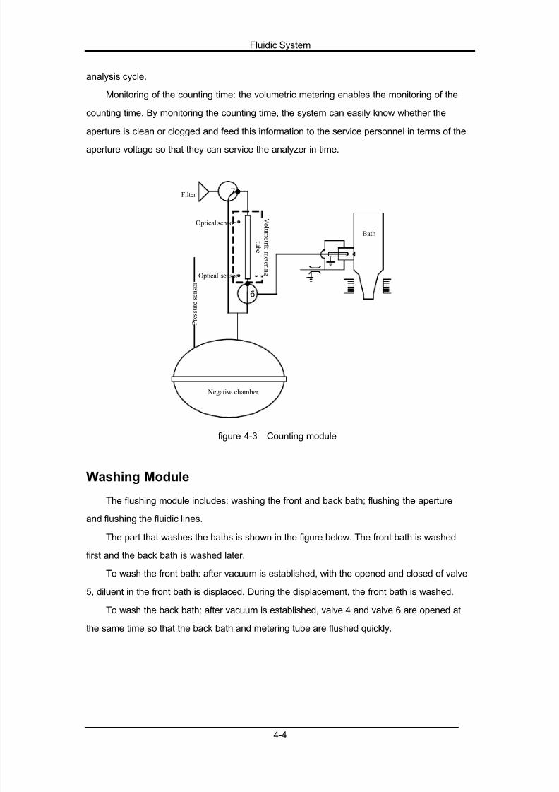
7/21/2019 BC 2300 Service
http://slidepdf.com/reader/full/bc-2300-service 52/88
Fluidic System
4-4
analysis cycle.
Monitoring of the counting time: the volumetric metering enables the monitoring of the
counting time. By monitoring the counting time, the system can easily know whether the
aperture is clean or clogged and feed this information to the service personnel in terms of the
aperture voltage so that they can service the analyzer in time.
7
P r e s s u r e s e n s o r
6
Negative chamber
V ol um e t r i c m e t e r i n
g
t u b e
Optical sensor
Optical sensor
Filter
Bath
figure 4-3 Counting module
Washing Module
The flushing module includes: washing the front and back bath; flushing the aperture
and flushing the fluidic lines.
The part that washes the baths is shown in the figure below. The front bath is washed
first and the back bath is washed later.
To wash the front bath: after vacuum is established, with the opened and closed of valve
5, diluent in the front bath is displaced. During the displacement, the front bath is washed.
To wash the back bath: after vacuum is established, valve 4 and valve 6 are opened at
the same time so that the back bath and metering tube are flushed quickly.

7/21/2019 BC 2300 Service
http://slidepdf.com/reader/full/bc-2300-service 53/88
Fluidic System
4-5
4
7
P r e s s u r e s e n s o r
6
5 Negative chamber
Diluent
Diluent
Bath
figure 4-4 Washing module of fluidic system#washing of front and back baths$
Hydraulic Module
Figure below shows the hydraulic module. This module serves to establish the negative
pressure and the positive pressure.
figure 4-5 Hydraulic module (the left establishes the pressure; the right establishes the
vacuum)
To establish positive pressure: when both valve 8 and the pump are opened, the
pump aspirates atmospheric air through the NC end of valve 8. The air is stored in the
pressure chamber to establish positive pressure. The pressure value, pump and valve are
monitored by the pressure sensor.

7/21/2019 BC 2300 Service
http://slidepdf.com/reader/full/bc-2300-service 54/88
Fluidic System
4-6
To establish negative pressure: when both valve 9 and the pump are opened, the
liquid and air in the pressure chamber are discharged through the path of the NO end of valve
8, the pump and the NC end of valve 9. At the same time, the vacuum is established and the
pressure value is monitored by the pressure sensor.
The pump is an imported American product.
Mixing Module
Bubble mixing method is applied here. As shown in the figure below, the aspirated
sample needs to be diluted before the counting. Once the sample is dispensed into the bath
containing a certain amount of dilute, the system will inform the mixing module to work. Then
the positive pressure is established inside the pressure chamber. Then the brief on/off of the
valve separates the air in the pressure chamber into several air segments and expels them
into the bath to introduce bubbles. The bubbles pop up from the bottom of the bath and the
mixing is done thus.
The on/off interval of the valve is critical to the effect of the bubble mixing. Either too
many or too few bubbles will affect the mixing. During the mixing process, the airway should
be well drained, or the trapped liquid will affect the quantity of the bubbles as well as the
dilution.
figure 4-6 Mixing module
Waste Discharging Module
The waste discharging includes: discharging the waste of the bath; discharging the

7/21/2019 BC 2300 Service
http://slidepdf.com/reader/full/bc-2300-service 55/88
Fluidic System
4-7
waste of pressure chamber. As shown in the figure below, once the negative pressure is
established inside the pressure chamber, valves 5 and 9 will open to discharge the waste of
the bath to the outside through the pressure chamber and the pump.
figure 4-7 Waste discharging module
Counting Timing
Usually in blood samples, the cells are too close to each other to be identified or
measured. For this reason, the diluent is used to separate the cells so that they are drawn
through the aperture one at a time as well as to create a conductive environment for blood
analysis. This analyzer can process two types of blood samples . whole blood samples and
prediluted blood samples.
Whole Blood Mode
To analyze a whole blood sample, the operator can simply present the sample to the
diluent dispenser and press the Diluent key to aspirate 20+L of the sample into the dispenser.
A diluted sample (about 1:300) will be dispensed when Diluent key is pressed the again. Mix
the sample thoroughly and present the well-mixed diluted sample under the sample suction
nozzle and press the [COUNT] key to aspirate sample into the analyzer .

7/21/2019 BC 2300 Service
http://slidepdf.com/reader/full/bc-2300-service 56/88
Fluidic System
4-8
20L of Whole blood
sample
6mL of diluent
About 1:300 dilution
30L
4mL of diluent
About 1:40000
dilution for the
RBC analysis
2.1mL
0.8mL of diluent
0.6mL of lyse
About 1:500dilution for the
WBC analysis
figure 4-8 Diluting procedure of whole blood mode
Predilute Mode
To analyze a capillary blood sample, the operator should first manually dilute the sample
(20+L of capillary sample needs to be diluted by 6mL of diluent) and then present the
pre-diluted sample to the sample suction nozzle and press the [COUNT] key to aspirate the
sample into the analyzer.
20uL of capillary
blood sample
6mL of diluent
About 1:300 dilution
30L
4mL of diluent
About 1:40000
dilution for the
RBC analysis
2.1mL0.94mL of
diluent
0.46mL of lyse
About 1:500
dilution for the
WBC analysis
figure 4-9 Diluting procedure of predilute mode

7/21/2019 BC 2300 Service
http://slidepdf.com/reader/full/bc-2300-service 57/88
Fluidic System
4-9
Volume Range of Blood Cells
After reacting with the diluent and lyse, the cell volumes mainly fall into the following
ranges:
WBC: 30-350fL
RBC: 25-250fL
PLT: 2-30fL

7/21/2019 BC 2300 Service
http://slidepdf.com/reader/full/bc-2300-service 58/88
5-1
5 Software
Executing of the Bootstrap Program
figure 5-1 Executing of the bootstrap program
1. Initializing the Nucleus OS: to establish the task and timer required by system
software and set them at the initialization state.
2. Configuring the FPGA: to write the FPGA configuration data into the FPGA.
3. Initializing the peripheral: to initialize 6 serial ports, Super I/O and the I2C bus line.
4. Loading the system software: to copy the system software in the DOM to the
designated memory and execute the software there.
5. For the convenience of designing, the bootstrap program is only displayed in English
in the center of the screen.
(1) "initializing# is displayed when the FPGA has configured.
(2) As shown in the figure below, the second point is displayed when the IDE DOM has
been found.
figure 5-2 Bootstrap software display
(3) After the system software in the DOM has been read, "initializing# is displayed, which
indicates the successful load of the system software, the end of the bootstrap and
the beginning of the loaded system software.
System Software Initialization
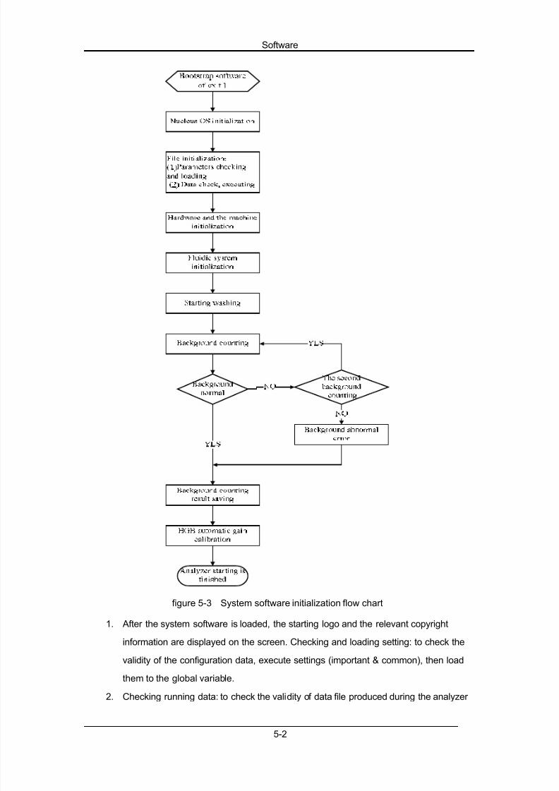
The flow chart of system software initialization is as follows.
7/21/2019 BC 2300 Service
http://slidepdf.com/reader/full/bc-2300-service 59/88
Software
5-2
figure 5-3 System software initialization flow chart
1. After the system software is loaded, the starting logo and the relevant copyright
information are displayed on the screen. Checking and loading setting: to check the
validity of the configuration data, execute settings (important & common), then load
them to the global variable.
2. Checking running data: to check the validity of data file produced during the analyzer

7/21/2019 BC 2300 Service
http://slidepdf.com/reader/full/bc-2300-service 60/88
Software
5-3
running, such as the sample data and the control data.
3. Initializing the hardware and the machine: to initialize the status and position of
some hardware ports and machine moving parts.
4. Initializing the fluidic system: to self-test some fluidic units and initialize the status of
the valves, pumps, constant-current source, zapping and HGB light.
5. The progress of files, hardware and fluidic initialization and the test result is
displayed at the bottom center of the screen.
6. Starting cleaning: to execute the corresponding cleaning sequence according to the
last shutdown mode. The system runs the background check after the cleaning is
finished.
7. The system enters the counting screen after the system software initialization is
finished.
Password
Level Password Operation menu Functions
count
(F5) digital oscillograph
(&) upgrade (including the version/configuration
upgrade )
review\table (F5) special function: derived data
review\histogram (F5) check the sample special information andthe numbers of valid samples
setup\setup items
other language, sequence number
gain fluidic system: the volume of the metering
tube
service\system
test
(machine assembly) motor adjustment
setup\logcheck the sequence log
(F2) derived log
1
service
engineer
(3210)
setup\configuration
check the high-level configuration
(F1) derived configuration
(F5) configuration comparison screen
setup\setup items
gain digital pot
count parameter unit, count time
(reference range)
general/man/woman/child/neonate
(other) background color of predilute mode
review\table (F5) special function: trend graph
calibrator\manual user calibrates manually
calibrator\auto user calibrates with calibrator
2administrator
(2826)
calibrator\fresh fresh blood calibration

7/21/2019 BC 2300 Service
http://slidepdf.com/reader/full/bc-2300-service 61/88
Software
5-4
3 user /
Software Upgrade
Upgrade Procedure
Upgrade the system software of the CPU through the upgrade disk. The upgrade
procedure is as follows:
1. Copy the contents need upgrading from the subdirectory in the disk to a new floppy
disk. Select all the content in the floppy disk and press the right key in the mouse to
remove the read-only attribute. If one floppy disk is not enough, open the
UPDATE.CFG file and in turn copy all the files in it to several floppy disks. The first
floppy disk must include the relevant UPDATE.CFG file.
2. When the analyzer starts, it enters the "Count# screen automatically.
3. Select "Setup%Password# screen to set the password to be service engineer level.
4. Select the "Count# screen and press [&]. The screen displays:
"Insert disk of config, then press [ENTER] key.#
5. Insert the upgrade disk in to the floppy disk driver and press [ENTER]. The screen
displays:
"Reading config file ...#
6. The original software reads the new upgrade file and analyzes the upgrade demand.
When the analysis is finished successfully, the screen displays:
"Insert disk of data, then press [ENTER] key.#
7. Press [ENTER] and the original software reads the new files to the temporary catalog.
8. If one floppy disk is not enough, the screen displays:
!Insert disk of following data then press [ENTER] key."
9. After the new file reads successfully, the screen displays:
"Writing files to disk or flash ...# 10. Then the original software reads the new file from the temporary catalog on the DOM,
write it into the working catalog and then delete the file in the temporary catalog. The
screen displays:
"Update is successes, wait for restarting ...#
11. The analyzer restarts automatically after several minutes.
12. The upgrade is finished successfully.

7/21/2019 BC 2300 Service
http://slidepdf.com/reader/full/bc-2300-service 62/88
Software
5-5
Notes and the Error Alarms
1. During the upgrade process, the operator should always stay with the analyzer and
mind every prompt in the analyzer.
2. During the upgrade process, the analyzer should be kept on. Or, the language
library will be damaged and cannot be loaded normally. To repair it, re-install the
DOM.
3. During the upgrade process, if "Delete the printing task first!# prompts, enter
"Service#% "Print# screen to delete all the print tasks before continuing the
upgrade.
4. During the upgrade process, if "Transmitting. Please wait.# prompts, enter
"Review%Sample Table Review%Transmit# screen to stop the transmitting task
first, and then continue the upgrade.
5. During the upgrade process, if message prompts again and again as follows:
"Insert disk of config, then press [ENTER] key.#
Or
"Insert disk of data, then press [ENTER] key.#
Check whether it is the right upgrade disk and if not, change another right disk to
re-upgrade. The analyzer will go back to the "Count# screen if the disk cannot read for
3 times.
6. If "Update is failured, contact to Mindray Co. Ltd.# displays, the analyzer will go
back to the "Count# screen after 5 seconds. The system software cannot be loaded
normally and "File error # may alarm in the future use. To repair it, re-install the
DOM.
Setup
The system settings are factory default at the analyzer !s first startup. To satisfy different
requirements, some settings may be customized. Some customization may require the
administrator password (2826). See the operation manual of BC-2300 for detailed setting.

7/21/2019 BC 2300 Service
http://slidepdf.com/reader/full/bc-2300-service 63/88
6-1
6 Histograms and Pulse Graphs
HistogramsThis section demonstrates some usual WBC histograms.
1. Normal histogram
NOTE :
Blood cells lain between the first and the second discriminators are lymphocyte;
those between the second and the third discriminators are mid-sized cells; those
between the third and the fourth discriminators are granulocyte. The fourth
discriminator is the fixed line.
2. No differential result because the WBC histogram is over-narrowly compressed.
3. No differential result because WBC count result is less than a certain value (WBC <
0.5).
4. No differential result because the peak of WBC histogram lies in the middle of the
histogram and thus cannot identify the type of peak cells.

7/21/2019 BC 2300 Service
http://slidepdf.com/reader/full/bc-2300-service 64/88
Histograms and Pulse Graphs
6-2
5. Increased nucleated erythrocytes or interference or inadequate hemolysis.
6. Severe interference in WBC channel (identifying if it is interfered by observing the
pulse graph)
7. No lyse reagent or poor hemolysis
8. Increased neutrophilic granulocytes
9. Increased lymphocytes
10. Tumor patient

7/21/2019 BC 2300 Service
http://slidepdf.com/reader/full/bc-2300-service 65/88
Histograms and Pulse Graphs
6-3
11. Increased mid-sized cells

7/21/2019 BC 2300 Service
http://slidepdf.com/reader/full/bc-2300-service 66/88
Histograms and Pulse Graphs
6-4
Pulse Graphs
After each count, the system can save the original sampling pulses of this time. We can
analyze the reason leading to the fault by viewing these original data.
Enter password "3210#, after a count, you can view the WBC pulse graph of this count by
pressing [F5] and view RBC pulse graph, PLT pulse graph by pressing [F1]. Presses [ENTER]
to exit.
When the instrument is working normally, the length of pulse data is related to the
concentration of the blood sample. The length of the pulse data should be within a limit range.
For general samples, the range should be:
WBC: < 1M RBC: < 600K PLT: < 1M
Length of normal level controls data should be:
WBC: 400 - 700K RBC: 250 - 450K PLT: 300 - 600K
Data length of abnormal sample will not lie in this range.
Normal Pulse Graphs
WBC pulse graph of normal sample Pulse graph of normal WBC background
RBC pulse graph of normal sample Pulse graph of normal RBC background

7/21/2019 BC 2300 Service
http://slidepdf.com/reader/full/bc-2300-service 67/88
Histograms and Pulse Graphs
6-5
PLT pulse graph of normal sample Pulse graph of normal PLT background
Abnormal Pulse Graphs
Severe interference in WBC channel
Data length increases obviously
(background)
Severe interference in WBC channel
Data length increases obviously
(normal sample)
Severe interference in RBC channel
Data length increases obviously
(background)
Severe interference in RBC channel
Data length increases obviously
(normal sample)

7/21/2019 BC 2300 Service
http://slidepdf.com/reader/full/bc-2300-service 68/88
Histograms and Pulse Graphs
6-6
Severe interference in PLT channel
Data length increases obviously
(background)
Severe interference in PLT channel
Data length increases obviously
(normal sample)
Interference occurs because
gain of PLT channel is too large
Data length increases (background count)
Interference occurs because
gain of PLT channel is too large
Data length increases (normal sample)
Slight interference in WBC channel
Data length does not increase obviously
(normal sample)
Inadequate or no hemolysis in WBC channel
Data length increases

7/21/2019 BC 2300 Service
http://slidepdf.com/reader/full/bc-2300-service 69/88
Histograms and Pulse Graphs
6-7
Slight interference in RBC channel
Data length does not increase obviously
(normal sample)
Sample of too dense concentration in RBC
channel
(Does not occur in normal situation)
Slight interference in PLT channel
Data length does not increase obviously
(normal sample)
Sample of too dense concentration
in PLT channel
(Does not occur in normal situation)
Interference in WBC channel
caused by inverter
Feature: sine wave with cycle of 20"26us
Measuring interference from inverter

7/21/2019 BC 2300 Service
http://slidepdf.com/reader/full/bc-2300-service 70/88
Histograms and Pulse Graphs
6-8
Insufficient liquid in WBC bath during count Interference in WBC channel from tubing
Feature: data length increases,
the base line of signal is not stabile.
Insufficient liquid in RBC bath during count Interference in RBC channel from tubing
Feature: data length increases,the base line of signal is not stabile.
Insufficient liquid in PLT bath during count Interference in PLT channel from tubing
Feature: data length increases,
the base line of signal is not stabile.

7/21/2019 BC 2300 Service
http://slidepdf.com/reader/full/bc-2300-service 71/88
7-1
7 Troubleshooting
The chapter deals with the codes, possible causes and solutions of the errors. If the
error remains after you have tried the recommended method, check the hardware and
replace the fittings or PCB boards which are suspected of causing the error.
This chapter consists of two parts, the first part dealing with the errors and assigned
error codes and the second possible causes and recommended solutions.
l Unless otherwise instructed, always turn off the power before trying to
assemble/disassemble your analyzer or fix the error.
l The leakage of the liquid from the analyzer can cause personnel injury or
property damage. In case of leakage, be sure to turn off the analyzer
immediately and wipe off the liquid.
l All the analyzer components and surfaces are potentially infectious, take
proper protective measures for operation or maintenance.
l Samples, controls, calibrators and waste are potentially infectious. Wear
proper personal protective equipment (e.g. gloves, lab coat, etc.) and follow
safe laboratory procedures when handling them in the laboratory.
l Be sure to keep you hair, clothes, cuffs or hands away from the moving
parts of this analyzer.
l Be sure to use specified tools or parts to maintain this analyzer and be sure
to clean the used tools as instructed by their instruction manual after the
maintenance is done.
l Be sure to use soft and clean cloth, or neutral detergent-soaked cloth
(twisted dry), or soft cloth washed by ethanol to clean the surface of this
analyzer.
l Be sure to pay attention to the marks or symbols on this analyzer. Be sure
not to touch the power socket at the back of this analyzer with wet hands or
wet rags.
l Be sure not to use organic solvent or acid/alkaline detergent to wash the
surface of this analyzer. Otherwise, the surface may fade or become
corrupted.
l Be sure to avoid direct contact with the reagents that will hurt your eyes,
skin and diaphragm.
l In case you spill the reagents on you skin, be sure to wash them off withmuch water. In case you spill the reagents into your eyes, be sure to

7/21/2019 BC 2300 Service
http://slidepdf.com/reader/full/bc-2300-service 72/88
Troubleshooting
7-2
immediately wash your eyes with much water and go see a doctor for further
treatment.

7/21/2019 BC 2300 Service
http://slidepdf.com/reader/full/bc-2300-service 73/88
Troubleshooting
7-3
Error Code
The errors recorded in the log are presented in the error codes. See table below for the
correspondence between the errors and error codes.
Table 7-1 Errors and codes
Code Error Code Error Code Error
0401
Environmental
Temperature
Abnormal
0402 Background
abnormal 0403 HGB error
0404 HGB adjust 0405 WBC clog 0406 WBC bubbles
0407 RBC clog 0408 RBC bubbles
0801Communication
error0802 Scanner error 0803
Scanner
communication error
1001Printer out of
paper1002
Printer
connection error1003
Recorder
communication error
1004Recorder out of
paper1005 Recorder too hot 1006 Press bar up
2001 Lyse out 2002 Diluent expired 2004 Lyse expired
2005
Negative
pressure filter
error
2006
Positive
pressure filter
error
2007 Real-time clock error
4002Syringe motor
error4005 A/D error 4008 Vacuum error
4009 Pressure error 400B Diluent out 400D Waste full
401156V power supply
error8001 File error 8002 Dynamic memory error

7/21/2019 BC 2300 Service
http://slidepdf.com/reader/full/bc-2300-service 74/88
Troubleshooting
7-4
Solutions
This chapter presents possible causes and solutions to be taken when the errors occur.
l Perform validation after removing the errors.
56V Error
Something is wrong with the 56V voltage on the analog board. and the operation to the
fluidic system is not allowed.
Solution:
Access "Service % Self-test# to test the 56V voltage.
The error will be cleared if the test result is normal. Otherwise, turn off the analyzer,
change the analog board, and then restart to check again.
A/D Error
Something is wrong with the A/D converter on the CPU board, and the operation to the
fluidic system is not allowed.
Solution:
Access "Service % Self-test % Circuit#. Test the A/D interrupt.
The error will be cleared if the test result is normal. Otherwise, change the CPU board
and restart the analyzer to check again.
Dynamic Memory Error
Something is wrong with the system memory.
Solution:
Turn off the analyzer and check the connecter or change the CPU board, and then
restart the analyzer to check again.

7/21/2019 BC 2300 Service
http://slidepdf.com/reader/full/bc-2300-service 75/88
Troubleshooting
7-5
HGB Error
HGB blank voltage is within 0V-3.2V or 4.9V-5V.
Solution:
Check the blank after the performance of probe cleanser cleansing. If the error cannot
be cleared, check the HGB blank voltage for several times. If the voltage is stable but out of
range, follow the procedure below,
1. Access "Setup ( Password# to gain the administrator authority.
2. Access "Setup ( Settings ( Gain# to adjust the HGB blank voltage to 3.4-4.8V
(4.5V recommended). If the cannot be cleared, try to clean the sending and
receiving end of the HGB shelf illuminant by a blower; wipe out the possible fluidic
leakage from the bath with lint free tissue.
HGB Adjustment
HGB blank voltage is within 3.2 - 3.4V or 4.8- 4.9V.
Solution:
Check the blank after the performance of probe cleanser cleansing. If the error cannot
be cleared, check the HGB blank voltage for several times. If the voltage is stable but out of
range, follow the procedure below,
1. Access "Setup ( Password# to gain the administrator authority.
2. Access "Setup ( Settings ( Gain# to adjust the HGB blank voltage to 3.4-4.8V
(4.5V recommended). If the cannot be cleared, try to clean the sending and
receiving end of the HGB shelf illuminant by a blower; wipe out the possible fluidic
leakage from the bath with lint free tissue.
If the error still remains, try to change the HGB shelf or such relevant parts as analog
board.
RBC Clog
This error message occurs when the actual RBC count time is greater than the preset
RBC count time by 2 seconds.
Possible causes:
Clogged aperture; inappropriate RBC count time settings or solenoid valve error.
Solution:

7/21/2019 BC 2300 Service
http://slidepdf.com/reader/full/bc-2300-service 76/88
Troubleshooting
7-6
1. Access "Service ( Maintenance# and do the "Zap aperture# and "Flush aperture#
procedures.
2. After unclogging, access "Setup ( Settings ( Count# to note down the preset
RBC count time. Access "Service ( Self-test (Tubing# and test the actual RBC
count time.
3. If the tested time differs from the preset time by less than 2 seconds, it means
the unclogging is successful and you can return to the Count screen to continue the
analysis. Otherwise, access "Service ( Maintenance# to soak the bath and tubing
with probe cleanser.
4. When the soaking is done, access "Setup ( Settings ( Count# to note down the
preset RBC count time. Access "Service ( Self-test ( Tubing# and test the
actual RBC count time.
5. If the tested time differs from the preset time by less than 2 seconds, it means
the unclogging is successful and you can return to the "Count# screen to continue
the analysis. If the difference is still greater than 2 seconds and stabilized around a
certain value, access "Setup ( Settings ( Count# to change the RBC count time
accordingly. After the adjustment, test the actual count time again and make sure
the difference is within 2 seconds.
6. If the error still remains, try to check whether the solenoid valve of the back bath is
clogged or the metering tube is polluted. Then check whether fluid runs along one
side of the metering tube wall during the analysis, if so, the count time may be
longer or when the count cycle stops cannot be detected.
7. The pollution of metering tube may be caused by rinse expired, remind the user of
using designated rinse within the expiration date. The circuit board of volumetric
unit may be not sensitive enough or the photocoulpler is damaged. Try to change
the relevant part.
RBC Bubbles
This error message occurs when the actual RBC count time is less than the preset RBC
count time by 2 seconds.
Possible causes:
Insufficient diluent or rinse;
Loose tubing connection;
Inappropriate RBC count time setting.
Solution:
1. Check whether the diluent or rinse is sufficient. If not, change a new container of
diluent of rinse.
2. Check the tubing connections. If necessary, reconnect the tubing.3. If the error still remains, access "Setup ( Password# to gain the administrator

7/21/2019 BC 2300 Service
http://slidepdf.com/reader/full/bc-2300-service 77/88
Troubleshooting
7-7
authority and then access "Setup ( Settings ( Count# and adjust the RBC count
time.
4. If the error still remains, check whether the air filter above the metering tube is dirty
or abnormal; if so, change it and than check again.
5. If the error still remains, check whether the solenoid valve between the air filter and
the metering tube is abnormal; if so, change the valve.
6. If the error still remains, check whether there is such air leakage as the solenoid
valve air leakage during the analysis; otherwise, check whether the photocoulpler !
sensitivity of the metering tube is abnormal; if so, readjust the sensitivity or change
the volumetric unit.
WBC Clog
This error message occurs when the actual WBC count time is greater than the preset
WBC count time by 2 seconds.
Possible causes:
Clogged aperture; Inappropriate WBC count time settings or solenoid valve error.
Solution:
Refer to solution of the RBC clog.
WBC BubblesThis error message occurs when the actual WBC count time is less than the preset WBC
count time by 2 seconds.
Possible causes:
Insufficient diluent or rinse;
Loose tubing connection)
Inappropriate WBC count time setting.
Solution:
Refer to the solution of RBC bubbles.
Background Abnormal
At least one parameter failed the background check.
Solution:
1. At the !Count# screen, press [F3] to do the startup procedure. If the error stillremains, access "Service Maintenance# and do the "Probe cleanser

7/21/2019 BC 2300 Service
http://slidepdf.com/reader/full/bc-2300-service 78/88
Troubleshooting
7-8
cleaning# procedure. After the cleaning is done, return to the "Count# screen and
check the background again to see whether the error is cleared.
2. If the error still remains, check whether the reagents are expired or polluted; if so,
change the reagents and check again; if not, check whether there is outer
interference.
3. Make sure that there is no such brushing type device as electric drill is working
discontinuously.
4. Make sure that the bath shielding box is properly connected, the shielding box is
properly connected to the analog board, and the analog board shielding box is
properly connected.
5. Make sure that the fluidic below the bath and back bath is not polluted; if so, do the
probe cleanser cleaning procedure. If the error still remains, change the tubing.
Printer Out of Paper
Possible cause:
The printing paper has run out or is not correctly installed.
Solution:
Check whether the printer is out of paper. If so, load paper to the printer; otherwise,
re-install the existing paper.
Printer Connection Error
Check whether the printer is well connected to the analyzer.
Waste Full
Possible cause:
1. The waste container is full.
2. After the performance of the analyzer !s first startup, draining the fluidic system or
turning on the analyzer after the packing performance.
Solution:
1. Check whether the container is full. If so, empty the container, or change a new
container to receive the waste.
2. If not, access the "Setup Setting Reagents# to re-set the waste container
volume according to the instruction 5.2.1 of the operation manual.

7/21/2019 BC 2300 Service
http://slidepdf.com/reader/full/bc-2300-service 79/88
Troubleshooting
7-9
Negative Filter Error
Something is wrong with the vacuum negative filter, the error is reported and the
operation to the fluidic system is not allowed.
Solution:
Access "Service Self-test Tubing# and test the negative pressure according to
the instruction 10.4.1 of the operation manual. The error will be cleared if the result is normal;
otherwise, try to change the negative filter connecting the valve 7 or check whether the fluidic
unit connecting the negative filter is free.
Environmental Temperature AbnormalPossible causes:
Abnormal environmental temperature or malfunctioning temperature sensor.
Solution:
Access "Service Status# and check the environmental temperature. If the
temperature exceeds the specified range by 15-30 , you need to adjust the work
environment of this analyzer so that the analyzer works in the required environment. If the
temperature is within the required range but the error remains, try to change the temperature
sensor or the CPU board and check again.
Recorder Out of Paper
Possible causes:
Recording paper has run out or is not correctly installed.
Solution:
Check whether the recording paper has run out. If so, load new paper; if not, re-install
the existing paper. If the error still remains, check whether there is remaining paper in the
recorder. If so, take it out and re-install paper; if not, try to restart the analyzer or change the
recorder.
Recorder Communication Error
Solution:

7/21/2019 BC 2300 Service
http://slidepdf.com/reader/full/bc-2300-service 80/88
Troubleshooting
7-10
Try to restart the analyzer. If the error is not cleared, change the recorder. If the error still
remains, try to change the relevant CPU board or power supply board.
Recorder Too HotPossible causes:
The recording head overheats.
Solution:
1. Stop using the recorder for some minutes to make it cooling.
2. If the error repeats, try to clean the rubber wheel of the print head; if the error still
remains, try to change the recorder.
Press Bar Up
Solution:
Check the recorder and do according to the step 1 then step 3 in the instruction 4.3.2 of
the operation manual. If the error still remains, try to change the recorder.
Real-Time Clock Error
Something is wrong with the clock, error is reported and the operation to the fluidic
system is not allowed.
Solution:
Access "Setup Settings Date & Time# and set the time and date according to
the instruction 5.2.3 of the operation manual, and then restart the analyzer to enable the new
settings. If the error still remains, try to change the 3V battery on the CPU board or the
relevant CPU board.
Scanner Error
Solution:
1. Check whether the scanner model is as required;
2. check whether the bar code is too long or is invalid;
3. check and make sure the bar code is correct.
4. If the error still remains, change the new barcode scanner or the relevant CPU
board.

7/21/2019 BC 2300 Service
http://slidepdf.com/reader/full/bc-2300-service 81/88
Troubleshooting
7-11
Scanner Communication Error
Something is wrong with the communication between the scanner and the analyzer.
Solution:
1. Check the connection between the two devices;
2. check whether the scanner model is as required.
Communication Error
Possible causes:
The received communication settings are different from the analyzer.
Solution:
Access "Setup Settings Print & comm. # and change the communication
settings according to the instruction 5.2.2 of the operation manual.
File Error
Something is wrong with file saving.
Solution:
Try to restart the analyzer. If the error is not cleared, try to insert the DOM on the CPU
board and restart the analyzer to check. If the error still remains, try to change the DOM or the
relevant CPU board.
Lyse Expired
Possible causes:
The lyse has expired or its expiration date is not correctly set and the operation to the
fluidic system is not allowed.
Solution:
Check whether the lyse has expired. If so, change a new container of lyse according to
the instruction 4.3.1 of the operation manual; if not, access "Setup Settings
Reagents# and adjust the expiration date according to the instruction 5.2.1 of the operation
manual.

7/21/2019 BC 2300 Service
http://slidepdf.com/reader/full/bc-2300-service 82/88
Troubleshooting
7-12
Diluent Expired
Possible causes:
The diluent has expired or its expiration date is not correctly set and the operation to the
fluidic system is not allowed.
Solution:
Check whether the diluent has expired. If so, change a new container of diluent
according to the instruction 4.3.1 of the operation manual; if not, access "Setup Settings
Reagents# and adjust the expiration date according to the instruction 5.2.1 of the
operation manual.
Lyse Out
Possible causes:
Insufficient lyse or wrong lyse volume setting; after the performance of the analyzer !s
first startup, draining the fluidic system or turning on the analyzer after the packing
performance.
Solution:
Check whether there is sufficient lyse left. If so, access "Setup Settings
Reagents# and adjust the remaining lyse volume according to the instruction 5.2.1 of the
operation manual; If not, change a new container of lyse according to the instruction 4.3.1 of
the operation manual.
Diluent Out
Possible causes:
insufficient diluent or wrong diluent volume setting; after the performance of the
analyzer !s first startup, draining the fluidic system or turning on the analyzer after the packing
performance.
Solution:
Check whether there is sufficient diluent left. If so, access !Setup Settings
Reagents# and adjust the remaining diluent volume according to the instruction 5.2.1 of the
operation manual; If not, change a new container of diluent according to the instruction 4.3.1
of the operation manual.
7/21/2019 BC 2300 Service
http://slidepdf.com/reader/full/bc-2300-service 83/88
Troubleshooting
7-13
Pressure Error
The vacuum chamber does not reach the expected pressure within the given time, the
error is reported and the operation to the fluidic system is not allowed.
Solution:
Access "Service Self-test Tubing# and test the pressure according to the
instructions 10.4.1 in the operation manual. The error will be cleared if the result is normal;
otherwise, check the relevant fluidic unit and analog board.
Vacuum Error
The system does not reach the expected vacuum within the given time, the error is
reported and the operation to the fluidic system is not allowed.
Solution:
Access "Service Self-test Tubing# and test the vacuum according to the
instructions 10.4.1 in the operation manual. The error will be cleared if the result is normal;
otherwise, check the relevant fluidic unit and analog board.
Positive Filter Error
The system does not reach the expected vacuum within the given time, the error is
reported and the operation to the fluidic system is not allowed.
Solution:
Access "Service Self-test Tubing# and test the positive filter according to the
instructions 10.4.1 in the operation manual. The error will be cleared if the result is normal;
otherwise, try to change the positive filter connecting with valve 8 or check whether the fluidic
unit connecting with the positive filter is free.
Syringe Motor Error
Possible causes:
Something is wrong with the motor that controls the syringe that aspirates/dispenses
samples and reagents.

7/21/2019 BC 2300 Service
http://slidepdf.com/reader/full/bc-2300-service 84/88
7-14
Solution:
Access "Service Self-test Machine# and test the motor according to the
instructions 10.4.2 in the operation manual. The error will be cleared if the result is normal;
otherwise, check the relevant machine part, fluidic unit, drive board and photocoupler
detecting part.
Note that the fluidic clog may also cause the syringe error; the fluidic should be checked
too.
l Be sure to keep you hair, clothes, cuffs or hands away from the motor the
analyzer is power on.

7/21/2019 BC 2300 Service
http://slidepdf.com/reader/full/bc-2300-service 85/88
8-1
8 List of Spare Parts
P/N Description
0000-10-10932 Keyboard (88 keys) KT-88
2800-30-28714 2800 recorder assembly
59BR-10-08830 ALPS PTMBL1306A thermal head
TR6D-30-16662 TR60-D recorder drive board
2002-20-55126-52 keypad panel
2800-30-28664 Keypad board
2800-30-28715 LCD assembly
900E-10-04913 INVERTOR CXA-L0612-VJL 'TDK'
0000-10-10907 Disk-on-module (32M) 44PIN 2.0mm 'M-SYSTEMS'2800-30-28650 CPU board
2002-30-55101 Analog board
2002-30-55102 Drive board
2800-30-28668 Volumetric metering board
2800-30-28670 Power supply board
2000-10-06120 Waste pump
2002-30-55229 bath assembly
2000-20-03124 Ruby Red Cell Counter 80um RB-22084
0030-30-13194 Bath assembly without ruby
2800-30-28815 HGB assembly
0030-10-13064 Syringe motor 43F4J-05-010 'HSI'
2800-30-28779 7.5mL syringe assembly
2800-30-28780 50+L syringe assembly
2002-20-55106 Shielding box cover
3001-10-07054 Air filter
3001-30-07273 Vacuum/pressure chamber
0030-30-07586 Three-way mini solenoid valve
0030-30-07587 Two-way mini solenoid valve
2800-30-28817 CAP component for LYSE
2800-30-28818 CAP component for DILUENT
0200-20-05560 Diluent dispenser
3003-20-34949 Isolation chamber

7/21/2019 BC 2300 Service
http://slidepdf.com/reader/full/bc-2300-service 86/88
List of Spare Parts
8-2
A Fluidic System
P r e s s u r e s e n s o r
D
i l u e n t
4
7
8
3
1
L y s e
9
B u f f e r
t u b i n g
1 0
B u f f e r
t u b i n g
S a m
p l e c u p
6
5
V a c
u u m / P r e s s u r e
c h a m b e r
W a s t e
2
7 . 5 m l
s y r i n g e
5 0 ! L
s y r i n g e
Pressure Sensor

7/21/2019 BC 2300 Service
http://slidepdf.com/reader/full/bc-2300-service 87/88
List of Spare Parts
8-3
B Error Code Description
Code Error
0401 Envir. temp. abnormal
0402 Background abnormal
0403 HGB error
0404 HGB adjust
0405 WBC clog
0406 WBC bubbles
0407 RBC clog
0408 RBC bubbles
0801 Communication error
0802Scanner error
0803 Scanner communication error
1001 Printer out of paper
1002 Printer connection error
1003 Recorder communication error
1004 Recorder out of paper
1005 Recorder too hot
1006 Press bar up
2001 Lyse out
2002 Diluent expired
2004 Lyse expired
2005 Negative filter error
2006 Positive filter error
2007 Real-time clock error
4002 Syringe motor error
4005 A/D error
4008 Vacuum error
4009 Press error
400B Diluent out
400D Waste full
4011 56V error
8001 File error
8002 Dynamic memory error

7/21/2019 BC 2300 Service
http://slidepdf.com/reader/full/bc-2300-service 88/88


![[XLS] - Mar15/District Reasi new proforma... · Web view2035 2300 2036 2300 2037 2300 2038 2300 2039 2300 2040 2300 2041 2300 2042 2300 2043 2300 2044 2300 2045 2300 2046 2300 2047](https://img.pdfslide.us/doc/110x75/5aa68dbc7f8b9a517d8ea409/xls-mar15district-reasi-new-proformaweb-view2035-2300-2036-2300-2037-2300.jpg)