Embed Size (px)
Citation preview

APRS@and the
TAPR EasyTrakTM
Az/EI Rotor Control System
Keith Sproul, WU2Z698 Magnolia Road
North Brunswick, NJ 08902
wu2z@ amsat.org
Abstract
APRS, Automatic Position Reporting System, has been used to track many things. It
has been used with DX Cluster for showing where the DX stations are located. It has
been used to track cars, boats, bicycles, motorcycles, weather balloons, and hot air
balloons. It has even been flown on the Energizer Bunny@ Hot Air Balloon many times.
When tracking balloons, especially the high-altitude weather balloons, normal antennas
work fine for the Packet/APRS/GPS signals. But when you are trying to receive ATV
(Amateur Television) signals from the balloon, you need much better antennas. Usually,
you need to have a high-gain antenna of some type pointed directly at the balloon.
APRS already knows where you are, and it knows where the other stations are. From
this information, it is easy to calculate the angle(s) needed to point a directional antenna
at the other station, when needed.
132

Uses of Rotor Control within APRS
Usually when people think of Rotor Control, they only think of either satellite tracking, or
rotor control for DX Chasing. Although these are the primary uses, there are other
situations where rotor control could be useful. The following table shows some possible
uses of rotor control within the APRS system.
Satellite Tracking Azimuth / ElevationI
Balloon Tracking Azimuth / Elevation
I DX / HF operation
Ground based vehicle tracking
Azimuth only
Azimuth only
Background
APRS has been used for tracking high-altitude balloon projects for many years.
MacAPRS/WinAPRS has features for predicting where the balloon will land even before
the balloon is launched. This software also has display features for showing altitude. ’
For normal APRS/GPS tracking operation with balloons, standard, omni-directional
antennas do fine. The data is 1200 baud packet, and 1 - 5 watts on 2meters or
440Mhz is adequate. However, when you try to transmit Amateur Television, (ATV)
signals, it is much harder to receive at great distances. Since the antenna on the
balloon cannot be directional, you have to make up for it with good antennas on the
ground. In the past, some groups have simply had a person manually pointing the
antenna at the balloon. As long as the balloon is in view, this works fine. After that, it is
just guessing. Also, this gets tiring very fast.
Computer controllable Rotor Controllers used to be complex and require special
interfaces. They were also quite expensive. With the introduction of the TAPR
EasyTrak Rotor Controller, ii this difficulty has been greatly reduced. This unit is also
significantly less expensive than some of the other rotor controllers on the market. See
the paper elsewhere in these proceedings about the details of this controller.
133

Software Design
If the world was flat, the calculations for tracking an object would be simple
trigonometry. But since we have to deal with a round world, the math becomes more
involved. In addition to having to do three-dimensional trig, we have to take into
consideration the fact that the altitude reported by the GPS is the altitude above sea
level at the current location of the balloon. The curvature of the earth has to be taken
into consideration and subtracted out, otherwise, the antenna would be pointed too.
high .
The rotor itself has to be considered. Most rotors are north-centered. Depending on
what you are doing, you may want a north-centered or south-centered rotor. When
tracking balloons from a temporary location, you need to consider where you locate
your ground station. If the rotor has to go through a ‘FLIP’, moving from one end of the
rotation limit all the way around to the other, you will loose valuable time. During that
time, the signal will be totally unusable because the antenna won’t be pointing in the
direction you need it to point.
Another thing to be concerned about is the fact that you don’t want to constantly move
the rotor, this could shorten the life of the rotor considerably. Therefore, you want to
know the beam width of the antenna array, and move the antenna only when needed.
Some rotor controllers already take this into account. The EasyTrack rotor controller has
a setting to tell it the ‘DEAD ZONE’. This is the number of degrees that the antenna has
to be told to move before it will actually rotate the antenna.
Not all devices that you will want to track will be configured to send altitude. In this
situation, the software realizes that the tracked device does not have altitude and does
not tell the rotor controller to set the elevation angle. This allows the operator to
manually adjust the elevation with the switches on the rotor controller, or manually from
the software on the computer. The software will not try to point the antenna below the
horizon.
The TAPR EasyTrak rotor controller uses a protocol called EasyComm. This is a simple
ASCII text protocol for controlling all of the features of the rotor. This protocol is easier
to use than the others and has more flexibility. It has also allowed the software to have
a few more features.
134
Rotor Control and Status Window
WinAPRS/MacAPRS/X-APRS has a Rotor Control Window that allows you manually
control the rotor and to display the current status of the rotor. This window can also be
used for making sure the antenna system is working properly. The following commands
are supported:
N Set the Azimuth rotor to point North.
S Set the Azimuth rotor to point South.
E Set the Azimuth rotor to point East.
W Set the Azimuth rotor to point West.
L Rotate Azimuth rotor Left 5 degrees.
R Rotate Azimuth rotor Right 5 degrees
V Set the Elevation rotor to point straight Vertical.
H Set the Elevation rotor to point at the Horizon.
U or+ Raise Elevation Up 5 degrees.
D or- Lower Elevation Down 5 degrees.
X o r * C Sends a CANCEL command to the rotor.
? or/ Query the rotor controller and update the display.
The arrow keys do the same things as the ‘L’, ‘R’, ‘U’, and ‘D’ keys.
Numeric Keypad The numeric keypad works as a control also.
5 Home (Azimuth 0, Elevation 0)
1-4, 6-9 Move the antenna in the appropriate direction, 1 degree at a time.
In the direction as they appear on the numeric keypad.
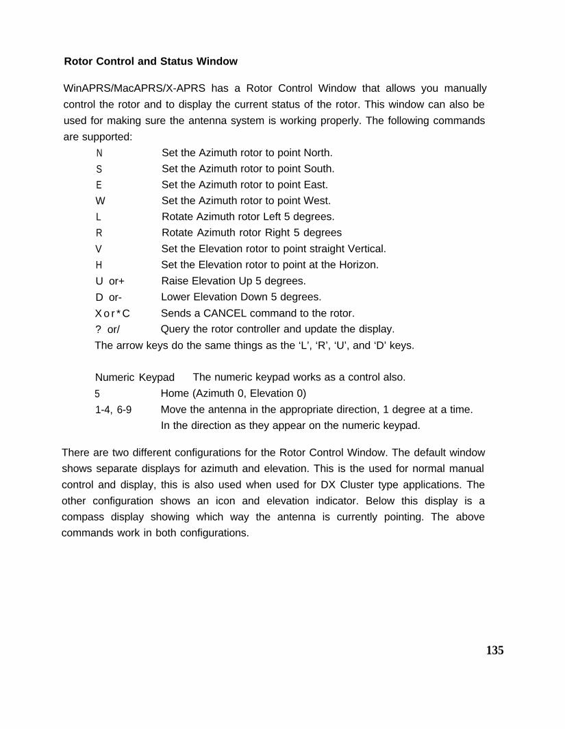
There are two different configurations for the Rotor Control Window. The default window
shows separate displays for azimuth and elevation. This is the used for normal manual
control and display, this is also used when used for DX Cluster type applications. The
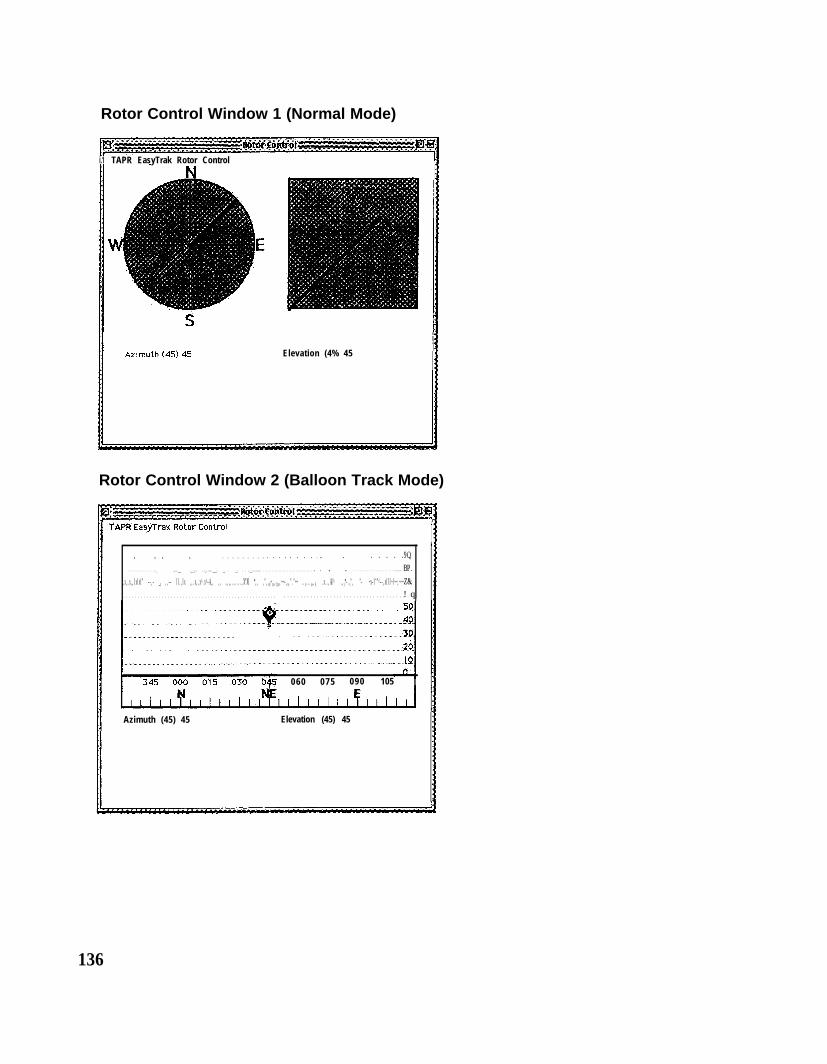
other configuration shows an icon and elevation indicator. Below this display is a
compass display showing which way the antenna is currently pointing. The above
commands work in both configurations.
135
Rotor Control Window 1 (Normal Mode)
i.1 TAPR EasyTrak Rotor Control
Elevation (4% 45
Rotor Control Window 2 (Balloon Track Mode)
9Q.. . . . . . .. . . . . . . . . . . . . . . . . . . . . . . . .. . . . . . . . . . . . . . . . . .._ .,...___ .__._... .._.....___. __. . __. . . ..__.......... . . . . . . . . . . . . . . . . . . . . . . . . . . . . . . . . . . . . . . . . . . . . . . . . . . . . . . . . . . . . . . . . . ............. ^BP.
,x,,x,,IxIxI" --,- _x ,,-- lI.,Ix ,,.x,,x^.x^-A,, ,, ,,,,.,....,X"XI *,, ,",,xI~xx,Ixxx.~~-,x,"."~~ Z&...x...a,,A .x..,AI^ .,x*-.x", "- ~x-I""^--,xIII~I~~,~~~ ^. . . . . . . . . . . . . . . . . . . . . . . . . . . . . . . . . . . . . . , . . . . . . . . . . . . ! q. . . . . . . . . . . . . . . . . . . . . . . . . . . . . . . . . . . . . . .
060 075 090 105
Azimuth (45) 45 Elevation (45) 45
136
DX Cluster Station Antenna Pointing
APRS has had the ability to understand DX Cluster data for a long time. Some people
have used this feature, but it has not been a major aspect of APRS. Once rotor control
ability was added to WinAPRS/MacAPRS/X-APRS, the ability to point to any station
was extremely simple to add.
You can also go to any of the Station List windows, select a station there, and hit ‘P’, it
will then POINT the rotor to that station. If the station you select does not have a valid
position report, it will ignore the command. If the station has a position and altitude, it
will rotate both the azimuth and elevation rotors. If the station does not have an altitude,
it will simply rotate the azimuth rotor.
Note: You can make it point to any station or object in APRS, it does not have to be a
DX station.
Automatic Weather Balloon Tracking
To use the Balloon Tracking feature of WinAPRS/MacAPRS/X-APRS, you need to
perform the following steps:
Select the station you want to track by opening up any of the Station Lists, then
hi-light the station you want to track. (The TRACKED STATIONS LIST is
recommended for this).
Type the letter ‘B’ for BALLOON TRACK.
(3) Watch the rotor follow the ‘balloon’
Note: The station you want to track does not have to be a balloon.
If the station is sending altitude, it will track azimuth and elevation. If the station is not
sending altitude, the software will only track azimuth. If this is the case, you can
manuallv control the elevation using the rotor control window described above.
Each time a
calculate the
balloon, it wil
antenna.
valid position report or elevation report is received, the program will
azimuth and elevation angles needed to keep the antenna pointed at the
I then send commands to the rotor controller to tell it where to point the
137

Automatic Weather Balloon Tracking Example
The map and rotor control windows below show a balloon in central Illinois. The track on
the map shows the balloon track soon after its maximum altitude. The antenna is
located at WU2Z-3 on the map. The rotor control window shows the azimuth and
elevation angles that the antenna was pointed at the time the last packet was received.
Balloon Tracking Map
D k t a n c e I S m i A l t i t u d e 7 4 3 2 4 I tD k t a n c e I S m i A l t i t u d e 7 4 3 2 4 I t
RR* XII’ Id”W
Ground Based Station Tracking
In most cases, if you are tracking a moving station, it is either close enough to be heard
direct, or there are digipeaters so that you are able to receive the data even when the
station is far away. If you are in an area that has few digipeaters, but want to be able to
track a car or other moving station, for further distances, it would be nice if you could
have a directional antenna automatically point at the moving station.
To make this work, for normal APRS type operation, you would need a vertically
polarized 2 meter yaggi on a rotor. Then, you select the station that you want to track,
just like you would if it were a balloon. WinAPRS/MacAPRS/X-APRS will then point the
antenna at the last known position of that station. Since the yagi has more gain than the
normal vertical antenna, you should be able to copy the signal at much greater
distances than you could if you were just using an omni-directional antenna.
138
Unfortunately, this cannot counter the affects of terrain. For example, this cannot
compensate for a car that disappears on the other side of a hill. This feature would be
most useful in areas that are flat, or when tracking boats. Since there are very few
digipeaters in the water, the tracking of boats is where this could be of greatest use.
If it were desirable to track many boats, or other moving stations, at one time using this
mechanism, the capabilities could be easily expanded. It would be easy to develop the
software where the system would point the antenna at one station, leave it there for a
couple of minutes, or until it received a position report, then rotate the antenna to the
next station, wait for a position report from that station, etc. The order in which it looked
at the stations would be optimized based on the least amount of antenna movement
and which station had the oldest position report. The logic and code for this feature has
been developed, but it is not currently in the released versions because it is doubtful if
anyone would truly use it. This feature has much more probability for use in the
commercial market. If anyone really wants this feature in the Ham version of
WinAPRS/MacAPRS/X-APRS, please contact the authors.
Ground Based Station Tracking Example
To show how Ground Based tracking works, we conducted an experiment. We set up
two stationary receive stations and one mobile station. The mobile station was
configured to not use any digipeaters, i.e. the path was not set.
Receive Station 1: Omni directional antenna, about 30 ‘ elevation.
Receive Station 2: 5 element yagi, with rotor control, about 30’ elevation..
Mobile Station: Omni directional antenna on my van with a Kenwood TM-D700
configured to transmit every 12 seconds, with medium power (25 watts).
This experiment was not done on 144.390 to avoid collisions with other APRS packets.
This also eliminated any possibility of digipeaters. The receive site is at the Apple Icon
at the bottom right of the map. The track is from my house to a hotel about 7 miles away
and back.
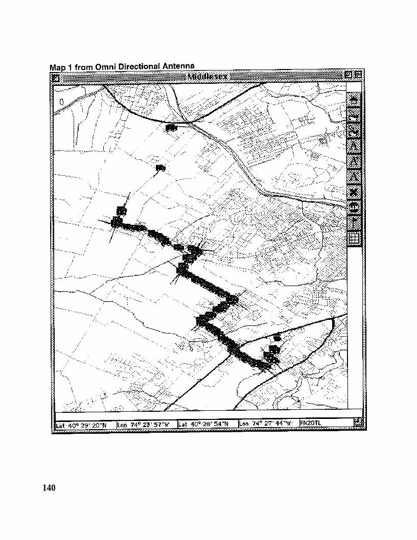
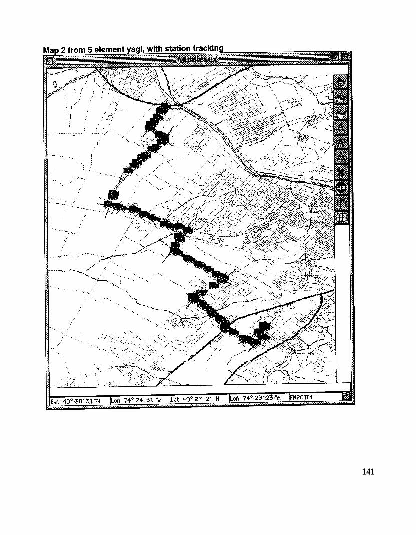
Below are the two maps showing the difference in received signals from the mobile
station. Map 1 shows the position reports received on the Omni directional antenna and
Map 2 shows the position reports received on the Yagi with station tracking.
139
140
141
Camera Tracking
Recent events have made using this system accurate enough to keep a camera pointed
at a moving object. Selective Availability has been turned off. This gives GPS an
accuracy of about 30 feet. The altitude has also greatly improved.
If you have a GPS and a D7 radio and have it set to transmit your position at least once
a minute or more, WinAPRS/MacAPRS/X-APRS could keep a camera pointed at you as
you walk around in the area within the view camera. To make this work, the camera
needs to be up high, and you have to have a fairly wide viewing angle since GPS still is
not exact. When doing this, you need to get an extremely accurate position and altitude
set for the camera location.
For this application, the accuracy of the Mic Encoder format is not good enough if you
want to have the camera track you real close to the camera. The Mic Encoder format
transmits accuracy of l/100 of a minute. If you use a GPS data transmitter, i.e. a TNC
set up to transmit the $GPGGA NMEA data, you can get much better accuracy. The
Garmin Ill+ sends data to l/1000 of a minute, or 10 times better than the Mic Encoder
format.
The good news is that the Kenwood D7 will do this also, but you have to configure it
from a computer and it doesn’t remember these settings if you turn the radio off or
change the TNC mode. The Palm Pilot works very good for configuring the D7 while out
walking around.
The settings in the 07 needed to do this are:
GPSTEXT $GPGGA GPGGA includes lat, Ion and altitude all in one line
LOCE3 Send the location every 30 seconds
The accuracy transmitted will now be the same as the accuracy that your GPS reports.
All GPS units transmit at least 2 digits, the Garmin GPS Ill+ transmits 3 and I have seen
a couple GPS units that actually transmit 4 digits of accuracy.
Comments
In all of the different uses of this system, it is extremely important to have the rotor
system calibrated accurately, and to make sure that it is pointed at TRUE NORTH, and
142
not Magnetic North. In New Jersey, the difference between true north and magnetic
north is about 12 degrees. This can make a big difference in the accuracy of the
system.
The original implementation uses the TAPR EasyTrak Rotor Controller, but the
capability is being expanded to include other rotor controllers as needed.
Currently, we support:
TAPR EasyTrak
Endeaver AutoTrack
Heathkit Intellirotor Azimuth rotor only
We are working on supporting the following:
EA4TX Automatic Rotor System (ARS), From Europe (Windows Only)
Yaesu GS-232
Hygain/MFJ DCU
Kachina 505AR Azimuth rotor only
The Heathkit Intellirotor works fine for DX type operations, but due to the nature of how
it operates, it is not well suited to track moving objects in real time.
Future
We are working on a rotatable antenna system on a car. The software could use the
GPS data to know where you are and which way your car is headed. It would then
adjust the antenna accordingly while driving. This would be most useful for chasing
balloons. This is being worked on, but we need to get a useable antenna system
designed before testing can start.
Garmin’s eTrax Summit GPS is a GPS with pressure based altitude sensor and a flux
gate compass built-in. Garmin just introduced an upgrade to this unit that includes
compass headings in the NMEA data stream. This gives us an easy way to get
HEADING information instead of BEARING information. This is important because the
143

BEARING is only accurate if you are moving. This makes the tracking from a car much
easier, especially if you want to go to someplace and park, then do your tracking while
stopped in the car.
For things like the camera tracker and tracking while moving in a car, it would be nice to
have a much faster rotor, but currently, there are none available commercially.
Now that WinAPRS/MacAPRS/X-APRS can point an antenna, satellite tracking would
be a next logical step.
Conclusion
This new addition to WinAPRS/MacAPRS/X-APRS has a lot of potential, for both the
balloon chaser, and the DX person. In addition, the simple tracking of a ground base
station can greatly improve the communications with stations at greater distances,
especially in areas with little or no digipeaters.
As APRS continues to develop, people will find more and more interesting things to do
with it.
Web Sites of Interest
http://aprs.rutgers.edu/
http://www.tapr.org/
http://www.kenwoodusa.com/
http://www.yaesu.com/
http://www.garmin.com/
http://dorm.rutaers.edu/balIoons/
http://dorm.rutaers.edu/-ksproul/pantilt.html
i Graphical Information Systems and Ham Radio, Keith Sproul, WU2Z, ARRL 14th
Digital Communications Conference, Arlington, Texas, September 8-1 Oth, 1995, pp 108-
118.
ii EasyTrak, A P/C Based Rotor Control lnerface, Steven Bible, N7HPR, ARRL 1 gth
Digital Communications Conference, Orlando, Florida, September 22-24th, 2000.
145


![[æ][ei ] A a [ei] [æ] name brave catcat badbad](https://img.pdfslide.us/doc/110x75/56649c935503460f9494f6df/aeei-a-a-ei-ae-name-brave-catcat-badbad.jpg)