Embed Size (px)
Citation preview
Inertial Sensors and Systems 2017
Karlsruhe, Germany
978-1-5386-3962-7/17/$31.00 ©2017 IEEE Pxx
Tactical grade MEMS accelerometer
S.Gonseth1, R.Brisson1, D Balmain1, M. Di-Gisi1
1 SAFRAN COLIBRYS SA
Av. des Sciences 13
1400 Yverdons-les-Bains
Switzerland
[2]
Abstract
SAFRAN COLIBRYS introduce the MS1000 accelerometer, a new class of high
performance MEMS accelerometer specially designed for inertial applications. It is based
on Colibrys’ long experience with MEMS technology and introduces an innovative design
solution to meet tactical grade requirements. This paper introduces the MS1000
architecture, reviews in detail the key performances of the product, and presents
qualification results.
1. Introduction
For more than 20 years, SAFRAN Colibrys have been developing MEMS accelerometers
for industrial, military, aeronautic, and safety applications. These sensors have proven to be
highly reliable in aggressive environments, like firing shocks up to 20’000g when used in
guided munitions and in the presence of heavy vibration with repetitive shocks. They can
even maintain their high performances over extreme temperature ranges up to +175°C,
making them suitable to serve the oil & gas market in applications like down-hole drilling.
Key features of this MEMS include robustness in harsh environments, maintaining full
performance over operational temperature for the sensor’s entire life, low power
consumption, and small size factor. A versatile accelerometer platform sensor has been
developed and qualified to meet the requirements of inertial navigation, tilt measurement,
vibration, and low noise acquisition, and can therefore cover the markets of aero & defence,
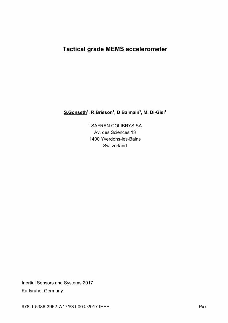
automotive testing, railway, and structural monitoring. Table 1, below, presents the new
1000 series accelerometers, each designed to address different needs for different market.
Table 1. 1000 series accelerometer platform
Vibration market Tilt for oil & gas
industry
Inertial tactical Seismic for structural
health monitoring
High bandwidth
2.5Khz ±5% or
5Khz ±3dB
Extended
temperature
up to 175°C
Long term bias
repeatability
1.2mg
Very low noise
1μg/√Hz
[3]
Basically, there are two ways of measuring acceleration with a MEMS sensor: either via an
open or closed loop configuration. In an open loop configuration, the capacitance change in
the MEMS is measured and amplified. In closed loop electronics the inertial forces are
compensated by electrostatic forces [1]. Although closed loop systems allow for reaching
better ultimate performance in terms of bias stability, linearity, and noise, there is a large
price to pay in terms of power (needs to be very precise and high voltage), size (driven by
the power supply requirements), and complexity (analogue and digital electronics).
The 1000 series is a new generation of open loop sensor that, as compared to closed loop
systems, has advantage in term of power and size, while still reaching the performances
required for high demanding inertial applications. It is also significantly less complex and
does not integrates embedded software. The 1000 series share the same ceramic leadless
chip carrier LCC20 package as 9000 series with is small form factor and excellent long term
reliability. This article reviews the MS1000 accelerometer which has been specifically
designed for inertial applications.
2. Design and technology
In order to achieve high performance and high reliability in harsh environments, a stable
mechanical sensor is necessary. This can be made up of a MEMS device and its associated
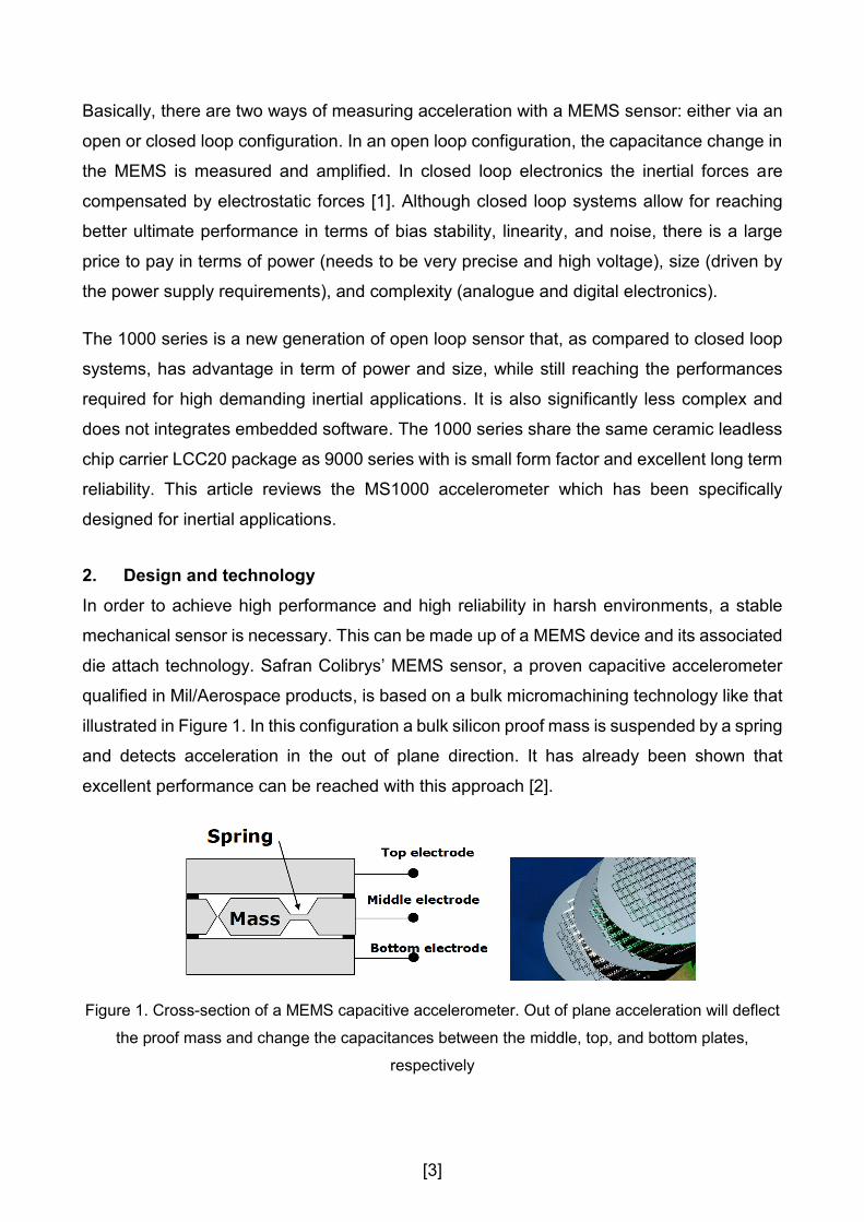
die attach technology. Safran Colibrys’ MEMS sensor, a proven capacitive accelerometer
qualified in Mil/Aerospace products, is based on a bulk micromachining technology like that
illustrated in Figure 1. In this configuration a bulk silicon proof mass is suspended by a spring
and detects acceleration in the out of plane direction. It has already been shown that
excellent performance can be reached with this approach [2].
Figure 1. Cross-section of a MEMS capacitive accelerometer. Out of plane acceleration will deflect
the proof mass and change the capacitances between the middle, top, and bottom plates,
respectively
[4]
The MS1000 is based on this same robust technology and introduces an innovative MEMS
device design and die attach technology which reduces its sensitivity to mounting stress and
therefore further improving bias stability.
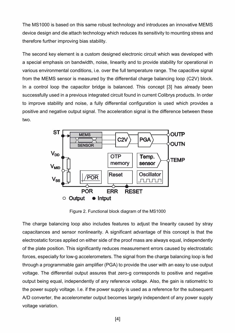
The second key element is a custom designed electronic circuit which was developed with
a special emphasis on bandwidth, noise, linearity and to provide stability for operational in
various environmental conditions, i.e. over the full temperature range. The capacitive signal
from the MEMS sensor is measured by the differential charge balancing loop (C2V) block.
In a control loop the capacitor bridge is balanced. This concept [3] has already been
successfully used in a previous integrated circuit found in current Colibrys products. In order
to improve stability and noise, a fully differential configuration is used which provides a
positive and negative output signal. The acceleration signal is the difference between these
two.
Figure 2. Functional block diagram of the MS1000
The charge balancing loop also includes features to adjust the linearity caused by stray
capacitances and sensor nonlinearity. A significant advantage of this concept is that the
electrostatic forces applied on either side of the proof mass are always equal, independently
of the plate position. This significantly reduces measurement errors caused by electrostatic
forces, especially for low-g accelerometers. The signal from the charge balancing loop is fed
through a programmable gain amplifier (PGA) to provide the user with an easy to use output
voltage. The differential output assures that zero-g corresponds to positive and negative
output being equal, independently of any reference voltage. Also, the gain is ratiometric to
the power supply voltage. I.e. if the power supply is used as a reference for the subsequent
A/D converter, the accelerometer output becomes largely independent of any power supply
voltage variation.
[5]
The service blocks include a One-Time Programmable (OTP) memory to store the
calibration data, an RC oscillator (clock), a power management function (POR), and a reset
block (Reset). The integrated circuit is designed to operate between -55°C and 125°C and
includes a temperature sensor that can be used for temperature correction by the user. It
operates at 3.3V, and uses less than 10mW.
3. Performance and qualification results
The performance of the MS1000 has been validated through the acceptance test procedure
(ATP) which is performed on 100% of devices during manufacturing, and through
complementary characterisations done in qualification. The MS1000 series production test
equipment have been totally renewed to enlarge the test coverage and to include all
standard calibration steps related to bias, scale factor, linearity, as well as the measurement
of the temperature sensor, frequency response, bias vibration rectification error, noise, and
a full temperature characterisation over the range of -40°C to 85°C. The following
paragraphs present MS1010 (10g sensor) key performances.
3.1 Linearity
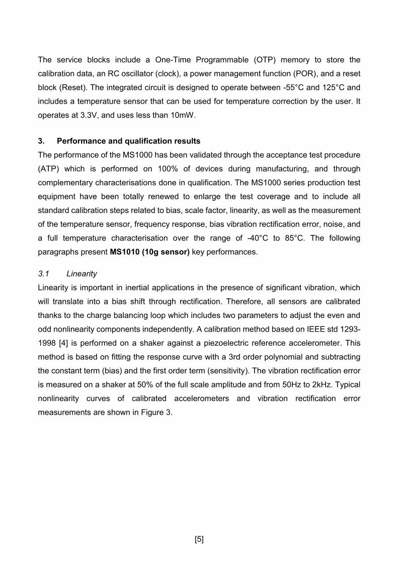
Linearity is important in inertial applications in the presence of significant vibration, which
will translate into a bias shift through rectification. Therefore, all sensors are calibrated
thanks to the charge balancing loop which includes two parameters to adjust the even and
odd nonlinearity components independently. A calibration method based on IEEE std 1293-
1998 [4] is performed on a shaker against a piezoelectric reference accelerometer. This
method is based on fitting the response curve with a 3rd order polynomial and subtracting
the constant term (bias) and the first order term (sensitivity). The vibration rectification error
is measured on a shaker at 50% of the full scale amplitude and from 50Hz to 2kHz. Typical
nonlinearity curves of calibrated accelerometers and vibration rectification error
measurements are shown in Figure 3.
[6]
Figure 3. MS1010 (10g sensor), IEEE non-linearity (left) and vibration rectification error (right)
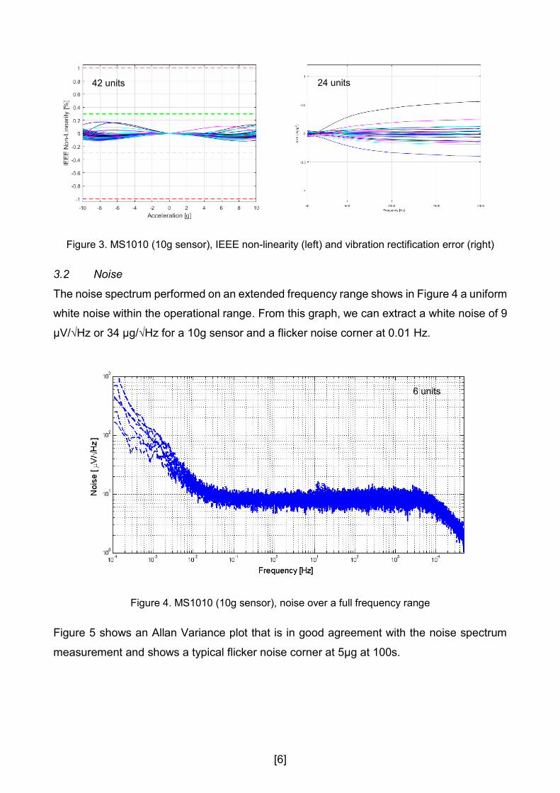
3.2 Noise
The noise spectrum performed on an extended frequency range shows in Figure 4 a uniform
white noise within the operational range. From this graph, we can extract a white noise of 9
µV/√Hz or 34 µg/√Hz for a 10g sensor and a flicker noise corner at 0.01 Hz.
Figure 4. MS1010 (10g sensor), noise over a full frequency range
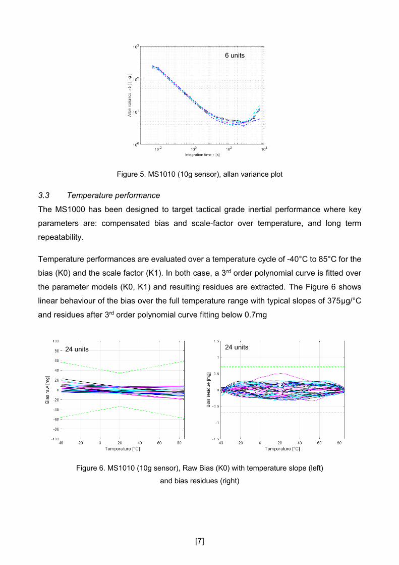
Figure 5 shows an Allan Variance plot that is in good agreement with the noise spectrum
measurement and shows a typical flicker noise corner at 5µg at 100s.
42 units 24 units
6 units
[7]
Figure 5. MS1010 (10g sensor), allan variance plot
3.3 Temperature performance
The MS1000 has been designed to target tactical grade inertial performance where key
parameters are: compensated bias and scale-factor over temperature, and long term
repeatability.
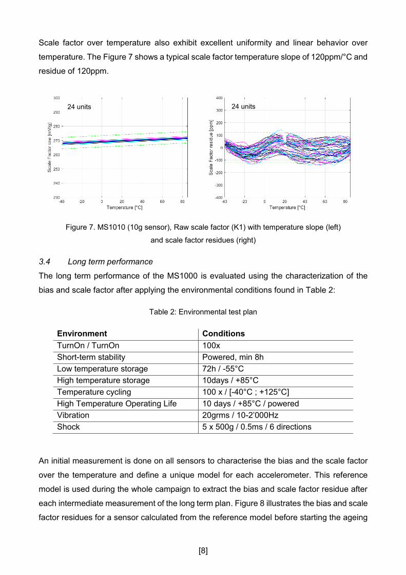
Temperature performances are evaluated over a temperature cycle of -40°C to 85°C for the
bias (K0) and the scale factor (K1). In both case, a 3rd order polynomial curve is fitted over
the parameter models (K0, K1) and resulting residues are extracted. The Figure 6 shows
linear behaviour of the bias over the full temperature range with typical slopes of 375µg/°C
and residues after 3rd order polynomial curve fitting below 0.7mg
Figure 6. MS1010 (10g sensor), Raw Bias (K0) with temperature slope (left)
and bias residues (right)
6 units
24 units 24 units
[8]
Scale factor over temperature also exhibit excellent uniformity and linear behavior over
temperature. The Figure 7 shows a typical scale factor temperature slope of 120ppm/°C and
residue of 120ppm.
Figure 7. MS1010 (10g sensor), Raw scale factor (K1) with temperature slope (left)
and scale factor residues (right)
3.4 Long term performance
The long term performance of the MS1000 is evaluated using the characterization of the
bias and scale factor after applying the environmental conditions found in Table 2:
Table 2: Environmental test plan
Environment Conditions
TurnOn / TurnOn 100x
Short-term stability Powered, min 8h
Low temperature storage 72h / -55°C
High temperature storage 10days / +85°C
Temperature cycling 100 x / [-40°C ; +125°C]
High Temperature Operating Life 10 days / +85°C / powered
Vibration 20grms / 10-2’000Hz
Shock 5 x 500g / 0.5ms / 6 directions
An initial measurement is done on all sensors to characterise the bias and the scale factor
over the temperature and define a unique model for each accelerometer. This reference
model is used during the whole campaign to extract the bias and scale factor residue after
each intermediate measurement of the long term plan. Figure 8 illustrates the bias and scale
factor residues for a sensor calculated from the reference model before starting the ageing
24 units 24 units
[9]
plan. The bias shows a limited hysteresis with a maximum bias residue of 0.3mg and a
maximum scale factor residue of 100ppm which highlight the efficiency of the new MEMS
design and is die attach process.
Figure 8. Bias and scale factor residue on a sensor extracted from the reference model on the
initial measurement.
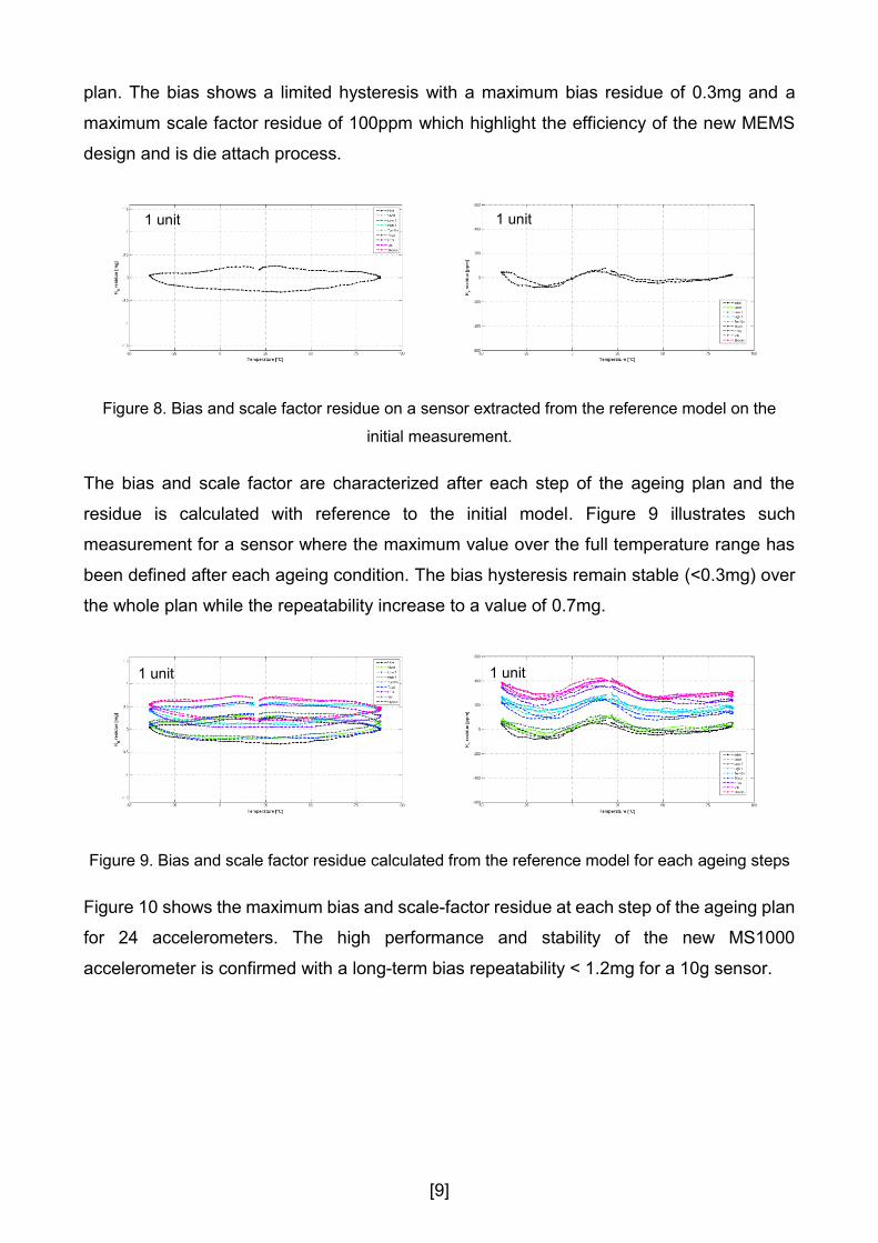
The bias and scale factor are characterized after each step of the ageing plan and the
residue is calculated with reference to the initial model. Figure 9 illustrates such
measurement for a sensor where the maximum value over the full temperature range has
been defined after each ageing condition. The bias hysteresis remain stable (<0.3mg) over
the whole plan while the repeatability increase to a value of 0.7mg.
Figure 9. Bias and scale factor residue calculated from the reference model for each ageing steps
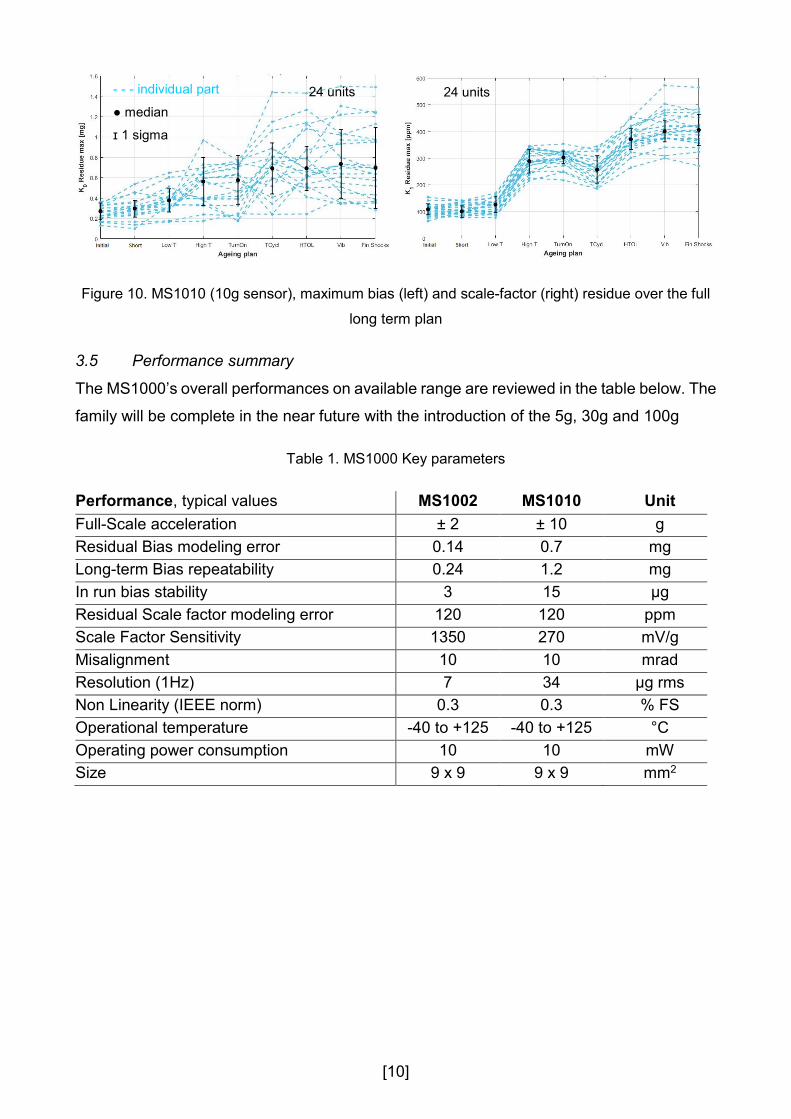
Figure 10 shows the maximum bias and scale-factor residue at each step of the ageing plan
for 24 accelerometers. The high performance and stability of the new MS1000
accelerometer is confirmed with a long-term bias repeatability < 1.2mg for a 10g sensor.
1 unit 1 unit
1 unit 1 unit
[10]
Figure 10. MS1010 (10g sensor), maximum bias (left) and scale-factor (right) residue over the full
long term plan
3.5 Performance summary
The MS1000’s overall performances on available range are reviewed in the table below. The
family will be complete in the near future with the introduction of the 5g, 30g and 100g
Table 1. MS1000 Key parameters
Performance, typical values MS1002 MS1010 Unit
Full-Scale acceleration ± 2 ± 10 g
Residual Bias modeling error 0.14 0.7 mg
Long-term Bias repeatability 0.24 1.2 mg
In run bias stability 3 15 µg
Residual Scale factor modeling error 120 120 ppm
Scale Factor Sensitivity 1350 270 mV/g
Misalignment 10 10 mrad
Resolution (1Hz) 7 34 µg rms
Non Linearity (IEEE norm) 0.3 0.3 % FS
Operational temperature -40 to +125 -40 to +125 °C
Operating power consumption 10 10 mW
Size 9 x 9 9 x 9 mm2
- - - individual part
● median
ɪ 1 sigma
24 units 24 units
[11]
4. Conclusion
SAFRAN COLIBRYS have more than 20 years of experience in manufacturing
accelerometer for industrial, military, aeronautic and safety applications. The MS1000, a
new class of high performance MEMS accelerometer specially designed for inertial
application, introduce innovative design solutions to meet tactical grade requirements.
Excellent thermal behaviour have been reported on a 10g sensor with bias residues of
0.7mg and scale-factor residue of 120ppm. The bias long term repeatability is one of the
key parameters for inertial application and the MS1000 shows a stability of 1.2mg.
The achieved performance shows the potential of MEMS technology to compete with quartz
servo accelerometers. Safran Colibrys has demonstrated is position in the high-end market,
ideally positioned to serve demanding applications in terms of performance and high
reliability under harsh environments.
[12]
5. References
[1] P. Zwahlen, D. Balmain, S. Habibi, P. Etter, F. Rudolf, R. Brisson, “Open-loop and
Closed-loop high-end accelerometer platforms for high demanding applications”,
Plan 2016, April 11-14 2016, Savannah, USA
[2] J-M. Stauffer, O.Dietrich, B. Dutoit, RS9000, “a Novel MEMS Accelerometer Family
for Mil/Aerospace and Safety Critical Applications”, IEEE/ION Position Location and
Navigation Symposium (PLANS), May 4-6 2010, Indian Wells, California, USA
[3] R. Le Reverend, “Device for measuring a force with the aid of a capacitive sensor
using charge transfer”, US patent US5821421
[4] IEEE std 1293-1998 – IEEE Standard Specification Format Guide and Test
Procedure for Linear Single-Axis, Nongyroscopic Acclerometers


![[TECHNICAL NOTES] Application of MEMS accelerometer to ... · [TECHNICAL NOTES] Application of MEMS accelerometer to ... Taking the advantage of its ... well as conventional geophysical](https://img.pdfslide.us/doc/110x75/5b93618b09d3f2a22a8d3063/technical-notes-application-of-mems-accelerometer-to-technical-notes.jpg)