Embed Size (px)
Citation preview
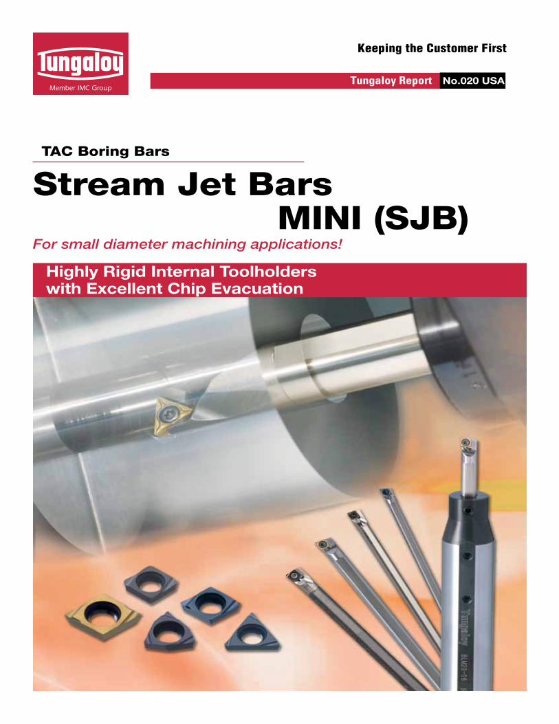
Keeping the Customer First
TAC Boring Bars
For small diameter machining applications!
Highly Rigid Internal Toolholders with Excellent Chip Evacuation
Tungaloy Report No.020 USA
Stream Jet Bars MINI (SJB)

2
3
1
New
PowerUp
Extensive simulation analysis has enabled Tungaloy to develop a highly-rigid Stream Jet Bar with the ideal tool geometry for excellent chip evacuation.
Applicable for a wide variety of machinesSleeves with Inch and metric O.D.'s are available
Seal cap* (optional)
Newly designed sleeve for directed external coolant flow (see picture below)
Stable tool life and excellent chip controlW08 type chipbreaker
Superior cutting edge due to fine grain carbide grade
Two grades of inserts: SH730 (for general purpose), TH10 (for non-ferrous)
Expansion of corner radius to include R0.1mm on “EPGT04” and “WBGT03” insert types
Excellent performance for small diameter machining operations Minimum bore diameters from ø.177 in
Steel and carbide shanks available
Straight shank type available
Can be used with internal coolant supply
Well designed chip pocket for excellent chip evacuation
Easy to adjust overhang due to marked scale on shank
Improved rigidity for minimizing bar deflection and chatter by FEM (Finite Element Method)
Added Z cutting edge style for back boring
Features
Stream Jet Bar MINI for small diameter machining applications!
Seal Cap* (Optional)
Chip pocket
Internal coolant supply
Attention: Please use the installation tools (e.g. a plastic hammer etc.), if difficult to ensure proper alignment
Screw (M6)
*optional parts: Coming soon
Stream Jet Bars MINI
2

ToolholderStock Min. Bore dia
ØDmDimensions (mm) Std
CornerRadius
rε
Applicable
Inserts
Parts Torque(N·m)R L ØDs f L1 L2 h f2 θ α Clamping Screw Wrench
A04F-SCLCR/L03-D050 l l 5 4 2.5 80 8 3.8 - 0˚ -15˚0.2 CCoo03X1 CSTA-1.6 T-6F 0.6
A05F-SCLCR/L03-D060 l l 6 5 3 80 9 4.8 - 0˚ -13˚
A06G-SCLCR/L04-D070 l l 7 6 3.5 90 11 5.75 - 0˚ -13˚0.2 CCoo04T1 CSTB-2 T-6F 0.6
A07G-SCLCR/L04-D080 l l 8 7 4 90 12 6.75 - 0˚ -11˚
SCLCR/L
SEXPR/L
0 10 20 30 40 50
SWUBR/L
STUPR/L
SEZPR/L
SCLCR/L
ToolholderStock Min. Bore dia
ØDmDimensions (mm) Std
CornerRadius
rε
Applicable
Inserts
Parts Torque(N·m)R L ØDs f L1 L2 h f2 θ α Screw Wrench
E04G-SCLCR/L03-D050 l l 5 4 2.5 90 9 3.8 - 0˚ -15˚0.2 CCoo03X1 CSTA-1.6 T-6F 0.6
E05G-SCLCR/L03-D060 l l 6 5 3 90 10 4.8 - 0˚ -13˚
E06H-SCLCR/L04-D070 l l 7 6 3.5 100 12 5.75 - 0˚ -13˚0.2 CCoo04T1 CSTB-2 T-6F 0.6
E07H-SCLCR/L04-D080 l l 8 7 4 100 14 6.75 - 0˚ -11˚
ØDm
α
h
θ
L2 L1
f
95°
ØD
s
List of Stream Jet Bars MINI A wide range of styles and sizes available
Boring & Internal Facing S-type (Positive, screw-on)
When using a right or left hand insert, the right hand insert is used for the left hand toolholders(SCLCL oo type), and the left hand insert is used for the right hand toolholders (SCLCR oo type).
■ Carbide shank
■ Steel shank
Cutting edge style L
: Stocked Standard
pg. 4Boring and facingInsert type: EPoo
pg. 2Boring and facingInsert type: CCoo
pg. 3BoringInsert type: WBoo
pg. 3BoringInsert type: TPoo
pg. 3Internal retractingInsert type: EPoo
ø4 ~ ø6
ø4 ~ ø6
ø4 ~ ø7
ø4 ~ ø7
ø5 ~ ø7
ø5 ~ ø7
ø7
ø7
ø4 ~ ø5
ø4 ~ ø5
ø5.5 ø6.5
ø5.5 ø6.5
ø4.5 ø7
ø4.5 ø7
ø6 ø8
ø5 ø8
ø5 ø8
ø8
ø8
ø6 ø8
Steel
Carbide
Steel
Carbide
Steel
Carbide
Steel
Carbide
Steel
Carbide
Style Shank Shank Minimum bore diameter (mm) type diameter
MINIPositive type
SCLCR/L
SEXPR/L
0 10 20 30 40 50
SWUBR/L
STUPR/L
SEZPR/L
3

SWUBR/L
ToolholderStock Min. Bore
dia
ØDm
Dimensions (mm) Std CornerRadiusrε
Applicable
Inserts
PartsTorque(N·m)
R L ØDs f L1 L2 h f2 θ α Clamping Screw Wrench
A05F-SWUBR/L03-D060 l l 6 5 3 80 9 4.8
- 0˚
-13˚
0.4 WBoo0301 CSTB-2 T-6F 0.6A06G-SWUBR/L03-D070 l l 7 6 3.5 90 11 5.75 -12˚
A07G-SWUBR/L03-D080 l l 8 7 4 90 12 6.75 -11˚
ToolholderStock Min. Bore
dia
ØDm
Dimensions (mm) Std CornerRadiusrε
Applicable
Inserts
PartsTorque(N·m)
R L ØDs f L1 L2 h f2 θ α Clamping Screw Wrench
E05G-SWUBR/L03-D060 l l 6 5 3 90 10 4.8
- 0˚
-13˚
0.4 WBoo0301 CSTB-2 T-6F 0.6E06H-SWUBR/L03-D070 l l 7 6 3.5 100 12 5.75 -12˚
E07H-SWUBR/L03-D080 l l 8 7 4 100 14 6.75 -11˚
STUPR/L
ToolholderStock Min. Bore
dia
ØDm
Dimensions (mm) Std CornerRadiusrε
Applicable
Inserts
Parts Torque(N·m)
R L ØDs f L1 L2 h f2 θ α Clamping Screw Wrench
A07G-STUPR/L07-D080 l l 8 7 4 90 12 6.75 0.4 +5˚ -10˚ 0.4 TPoo0701 CSTB-2.2L038 T-7F 0.9
ToolholderStock Min. Bore
dia
ØDm
Dimensions (mm) Std CornerRadiusrε
Applicable
Inserts
Parts Torque(N·m)
R L ØDs f L1 L2 h f2 θ α Clamping Screw Wrench
E07H-STUPR/L07-D080 l l 8 7 4 100 14 6.75 0.3 +5˚ -10˚ 0.4 TPoo0701 CSTB-2.2L038 T-7F 0.9
L1
95°
f
f 2
ØDm
α
ØD
s
h
θ
L2
ØD
s
f
93°
θ
hØDm
α
L2 L1
Boring S-type (Positive, screw-on)
■ Steel shank
■ Carbide shank
Boring S-type (Positive, screw-on)
■ Steel shank
■ Carbide shank
: Stocked Standard
Cutting edge style U
Right hand (R) shown
Right hand (R) shown
Cutting edge style U
When using a right or left hand insert, the right hand insert (R) is used for the left hand toolholders(STUPL oo type), and the left hand insert (L) is used for the right hand toolholders (STUPR oo type).
When using a right or left hand insert, the right hand insert (R) is used for the left hand toolholders(SWUBL oo type), and the left hand insert (L) is used for the right hand toolholders (SWUBR oo type).
Stream Jet Bars MINI
4

ToolholderStock Min. Bore
dia Dimensions (mm) Std CornerRadius
rε
Applicable
Inserts
PartsTorque(N·m)
R L ØDm ØDs f L1 L2 h f2 θ α Clamping Screw Wrench
A04F-SEZPR/L03-D055 l l 5.5 4 3.2 80 4 3.81.2 0˚
-8˚0.2 EPoo03X1 CSTA-1.6 T-6F 0.6
A05F-SEZPR/L03-D065 l l 6.5 5 3.7 80 5 4.8 -6˚
SEXPR/L
ToolholderStock Min. Bore
dia
ØDm
Dimensions (mm) Std CornerRadius
rε
Applicable
Inserts
PartsTorque(N·m)
R L ØDs f L1 L2 h f2 θ α Clamping Screw Wrench
A04F-SEXPR/L03-D045 l l 4.5 4 2.3 80 8 3.8 - 0˚ -15˚0.2 EPoo03X1 CSTA-1.6 T-6F 0.6
A04F-SEXPR/L03-D050 l l 5 4 2.5 80 8 3.8 - 0˚ -13˚
A05F-SEXPR/L04-D055 l l 5.5 5 2.75 80 9 4.8 - 0˚ -12˚0.4 EPoo0401 CSTB-2 T-6F 0.6
A06G-SEXPR/L04-D070 l l 7 6 3.6 90 11 5.75 - 0˚ -12˚
ToolholderStock Min. Bore
dia
ØDm
Dimensions (mm) Std CornerRadius
rε
Applicable
Inserts
PartsTorque(N·m)
R L ØDs f L1 L2 h f2 θ α Clamping Screw Wrench
E04G-SEXPR/L03-D045 l l 4.5 4 2.3 90 9 3.8 - 0˚ -15˚0.2 EPoo03X1 CSTA-1.6 T-6F 0.6
E04G-SEXPR/L03-D050 l l 5 4 2.5 90 9 3.8 - 0˚ -13˚
E05G-SEXPR/L04-D055 l l 5.5 5 2.75 90 10 4.8 - 0˚ -12˚0.4 EPoo0401 CSTB-2 T-6F 0.6
E06H-SEXPR/L04-D070 l l 7 6 3.6 100 12 5.75 - 0˚ -12˚
ToolholderStock Min. Bore
dia Dimensions (mm) Std CornerRadius
rε
Applicable
Inserts
PartsTorque(N·m)
R L ØDm ØDs f L1 L2 h f2 θ α Clamping Screw Wrench
E04G-SEZPR/L03-D055 l l 5.5 4 3.2 90 5 3.81.2 0˚
-8˚0.2 EPoo03X1 CSTA-1.6 T-6F 0.6
E05G-SEZPR/L03-D065 l l 6.5 5 3.7 90 6 4.8 -6˚
95°
f
L2 f 2 L1
ØDm h
θα
ØD
s
f
ØDm
αL2 L1
h
θ
100°
ØD
s
: Stocked Standard
■ Steel shank
■ Carbide shank
■ Steel shank
■ Carbide shank
S-type (Positive, screw-on)
S-type (Positive, screw-on)Internal retracting
Boring & Internal Facing
Cutting edge style Z Right hand (R) shown
Cutting edge style X Right hand (R) shown
When using a right or left hand insert, the right hand insert (R) is used for the right hand toolholders(SEZPR oo type), and the left hand insert (L) is used for the left hand toolholders (SEZPL oo type).
When using a right or left hand insert, the right hand insert (R) is used for the left hand toolholders (SEXPL oo type), and the left hand insert (L) is used for the right hand toolholders (SEXPR oo type).
SEZPR/L
5

ød s ød1 rεW08 WBGT030100R-W08
3.97 1.59 2.3
0.03l
WBGT030100L-W08 l l lWBGT030101R-W08
0.10l
WBGT030101L-W08 l lWBGT030102R-W08
0.20l
WBGT030102L-W08 l l l lWBGT030104R-W08
0.40l
WBGT030104L-W08 l l l l
15º
SH
730
GH
110
NS
530
TH10
UX
30
ød s ød1 rεW08 EPGT03X100R-W08
3.57 1.39 1.9
0.03l l
EPGT03X100L-W08 l lEPGT03X101R-W08
0.10l l
EPGT03X101L-W08 l lEPGT03X102R-W08
0.20l l
EPGT03X102L-W08 l lEPGT03X104R-W08
0.40l l
EPGT03X104L-W08 l lEPGT040100R-W08
3.97 1.59 2.3
0.03l l
EPGT040100L-W08 l l l lEPGT040101R-W08
0.10l l
EPGT040101L-W08 l lEPGT040102R-W08
0.20l l l l
EPGT040102L-W08 l l l lEPGT040104R-W08
0.40l l l l
EPGT040104L-W08 l l l l
J08 EPGT040100L-J083.97 1.59 2.3
0.03 lEPGT040102L-J08 0.20 lEPGT040104L-J08 0.40 l
ød s ød1 rεSH730 TH10
W08 CCGT03X100R-W08
3.57 1.39 1.9
0.03l l
CCGT03X100L-W08 l lCCGT03X101R-W08
0.10l l
CCGT03X101L-W08 l lCCGT03X102R-W08
0.20l l
CCGT03X102L-W08 l lCCGT03X104R-W08
0.40l l
CCGT03X104L-W08 l lCCGT04T100R-W08
4.37 1.79 2.3
0.03l l
CCGT04T100L-W08 l lCCGT04T101R-W08
0.10l l
CCGT04T101L-W08 l lCCGT04T102R-W08
0.20l l
CCGT04T102L-W08 l lCCGT04T104R-W08
0.40l l
CCGT04T104L-W08 l l
15º
15º
15º
SH
730
J740
GH
110
NS
530
GT5
30
TH10
UX
30
Chipbreaker
Appearance (Cross section)
Insert Cat. No. (Metric)
Ap
plic
atio
n
I.C. dia. Thickness Hole dia.(Ø) Corner radius
Dimensions (mm)Grades
80° Hexagon, 5° positive with hole
Fin
ishi
ng
Coated CarbideCermet
80° Rhombic, 7° positive with hole
75° Rhombic, 11° positive with hole
Chipbreaker
Chipbreaker
Appearance (Cross section)
Appearance (Cross section)
Insert Cat. No. (Metric)
Insert Cat. No. (Metric)
Ap
plic
atio
nA
pp
licat
ion
I.C. dia.
I.C. dia.
Thickness
Thickness
Hole dia.(Ø)
Hole dia.(Ø)
Coated
Coated
Corner radius
Corner radius
Dimensions (mm)
Dimensions (mm)
Grades
Grades
Carbide
CarbideCermet
Inserts for small diameter applicationsF
inis
hing
Fin
ishi
ngF
or
smal
l
lath
es w
ith
honi
ng
: Stocked Standard
: Stocked in Japan
Stream Jet Bars MINI
6

ød s ød1 rεSH730 TH10
W08 TPGT070100R-W08
4.37 1.59 2.58
0.03 l lTPGT070100L-W08 l lTPGT070101R-W08 0.10 l lTPGT070101L-W08 l lTPGT070102R-W08 0.20 l lTPGT070102L-W08 l lTPGT070104R-W08 0.40 l lTPGT070104L-W08 l l
15º
øDo øDi øDn L1 h b S1 S2 S3 A B C
BLM159-04 l
15.875
4
15 100 15 15.875 5
15 15
SSHM4-4 SSHM4-4 SSHM4-4 P-2CA-16(M6)
BLM159-05 l 5
BLM159-06 l 620 20
BLM159-07 l 7
BLM16-04 l
16
4
15 100 15 16 5
15 15
SSHM4-4 SSHM4-4 SSHM4-4 P-2CA-16(M6)
BLM16-05 l 5
BLM16-06 l 620 20
BLM16-07 l 7
BLM19-04 l
19.05
4
18 100 18 19.05 5
15 15
SSHM4-4
SSHM4-6 SSHM4-6
P-2CA-16(M6)
BLM19-05 l 5
SSHM4-4 SSHM4-4BLM19-06 l 620 20
BLM19-07 l 7
BLM20-04 l
20
4 13
100 19 20 5
15 15
SSHM4-4
SSHM4-6 SSHM4-6
P-2CA-16(M6)
BLM20-05 l 5 14
BLM20-06 l 6 1520 20 SSHM4-4 SSHM4-4
BLM20-07 l 7 16
BLM22-04 l
22
4 13
125 21 22 5
15 15
SSHM4-4 SSHM4-6 SSHM4-6 P-2CA-16(M6)
BLM22-05 l 5 14
BLM22-06 l 6 1520 20
BLM22-07 l 7 16
BLM25-04 l
25
4 13
125 24 25 5
15 15
SSHM4-4SSHM4-8 SSHM4-8
P-2CA-16(M6)
BLM25-05 l 5 14
BLM25-06 l 6 1520 20
BLM25-07 l 7 16 SSHM4-6 SSHM4-6
BLM254-04 l
25.4
4 13
125 24 25.4 5
15 15
SSHM4-4SSHM4-8 SSHM4-8
P-2CA-16(M6)
BLM254-05 l 5 14
BLM254-06 l 6 1520 20
BLM254-07 l 7 16 SSHM4-6 SSHM4-6
10 L1
h
b ØD
n
ØD
i
ØD
O
S1
A B C
S2 S3
Chipbreaker
Appearance (Cross section)
Insert Cat. No. (Metric)
Ap
plic
atio
n
I.C. dia. Thickness Hole dia.(Ø) Corner radius
Dimensions (mm) Grades
: Stocked Standard
60° Triangular, 11° positive with holeF
inis
hing
Coated Carbide
Sleeves BLM type (Round shank for Stream Jet Bar MINI)
*Seal cap (optional): Available Late 2010
Seal cap*(Inner screw)WrenchCat. No. Stock
Dimensions (mm) Replacement parts
7

Vc (SFM) ap (in) f (in/rev)
R0.03 R0.1 R0.2 R0.4
W08
J08 SH730
GH110
160 - 500
.002 ~ .025
.001 .004 .008 .015
W08
200 - 400
.0003 ~ .0008 .0004 ~ .002 .0007 ~ .004 .002 ~ .005TH10
200 - 500
500 - 1200
SH730 100 - 200
: E07K-SCLCR04-D080 : CCGT04T102L-W08 (SH730)
: A04F-SCLCR03-D050 : CCGT03X104L-W08 (SH730)
0.315 in
ø0.3
94
0.118 in
ø0.1
97 in
Steels1008 - 1045 SAE
Stainless steelsSUS303, SUS304 etc.
Grey cast ironsDuctile cast irons FC250, FCD450 etc.
Aluminium alloysCopper alloys
Si < 13%
Titanium Titanium alloys
Ti-6Al-4V etc.
Work material Chip-breaker Grades Cutting Speed Depth of cut Feed
Standard cutting conditions
ToolholderInsert
ToolholderInsert
Work materialCutting speedDepth of cutFeedCutting fluid
Work materialCutting speedDepth of cutFeedCutting fluid
Stream Jet Bar 400 pcs.
300 pcs.Competitor
Stream Jet Bar1000 pcs.
500 pcs.Competitor
Practical examples
30 % increased tool life
Twice increased tool life
: 1045 SAE : Vc = 160 SFM: ap = 0.006 in: f = 0.002 in/rev: Water soluble type (Internal supply)
: 52100 Bearing Steel : Vc = 80 SFM: ap = 0.008 in: f = 0.002 in/rev: Cutting oil(external supply)
SJB MINI accomplished 30% longer tool life with excellent surface roughness than the competitor's product.
NEW ADDRESS
Summer 2010
Distributed By:
www.tungaloyamerica.com
Tungaloy America, Inc.1226A Michael Drive, Wood Dale, IL 601913726 N. Ventura Dr. Arlington Heights, IL 60004Inside Sales : 1-888-554-8394Technical Support: 1-888-554-8391Fax: 1-888-554-8392
Tungaloy Canada432 Elgin Street, Unit 3, Brantford, Ontario, Canada N3S-7P7Phone: 519-758-5779, Fax: 519-758-5791
Tungaloy de Mexico S.A.C Los Arellano 113, Vista Alegre,Aguascalientes, AGS, Mexico 20290Phone: 011-52-449-929-5410, Fax: 011-52-449-929-5411
Follow us on Twitter @tungaloy
Become a fan on facebook
Watch us on You Tube