Embed Size (px)
Citation preview
Copyright © 2016 ComAp a.s.Written byRoman TaragelPrague, Czech RepublicComAp a.s., Kundratka 2359/17,180 00 Praha 8, Czech RepublicTel: +420 246 012 111, Fax: +420 266 316 647E-mail: [email protected], www.comap.cz Reference Guide
EletronicEngines Support
SW version 6.51 Document information 7
2 Principle of ECU support 9
3 List of ECU 28
4 List of texts of ECU fault codes 233
ComApEletronicEnginesSupport 2
Table of contents1 Document information 7
1.1 Clarification of notation 7
1.2 About this guide 7
1.3 Legal notice 7
2 Principle of ECU support 9
2.1What must be done to support a new ECU? 9
2.2What data can be transmitted to / from ECU? 10
2.3What is an ESL file? 10
2.4What is the default ESL setting? 11
2.5 How to import ESC - ESL package? 11
2.6Why ESC and ECU list have different versions? 11
2.7 Configuration 11
2.7.1 InteliNanoNT 11
2.7.2 InteliDrive Nano 12
2.7.3 InteliLiteNT, InteliCompactNT 13
2.7.4 InteliLite 14
2.7.5 InteliDrive Lite 15
2.7.6 InteliDrive DCU , InteliDriveMobile 16
2.7.7 InteliGenNT, InteliSysNT 16
2.8 Proprietary (non J1939) ECU/protocols 17
2.9 SAE - J1939 diagnostic connector 17
2.10 Fault codes – FMI table 18
2.11 How to create a constant for ECU control 19
2.12 After-treatment support (Tier4) 19
2.13 Comparison table 23
3 List of ECU 28
3.1 Agco Power engines support 29
3.1.1 EEM4 29
3.2 Caterpillar engines support 32
3.2.1 CCMwith ADEM or EMCP2 32
3.2.2 PL1000 with ADEM or EMCP2 33
3.2.3 ADEM A3 or ADEM A4 34
3.2.4 ADEM A4with EMCP3.x or EMCP4.x 37
3.3 Cummins engines support 41
3.3.1 CM500 41
ComApEletronicEnginesSupport 3
3.3.2 CM558 43
3.3.3 CM570 45
3.3.4 CM800 47
3.3.5 CM850 49
3.3.6 CM2150 53
3.3.7 CM2250 (Industrial calibration) 56
3.3.8 CM2350 58
3.3.9 PGI Interface (CM850 / CM2150 / CM2250) 62
3.3.10 GCS 64
3.4 Daimler Chrysler engines support 68
3.4.1 ADM2 68
3.4.2 ADM3 70
3.5 Detroit Diesel engines support 73
3.5.1 DDEC IV 73
3.5.2 DDEC V 75
3.6 Deutz engines support 78
3.6.1 Engine type explanation 78
3.6.2 EMR2 79
3.6.3 EMR3-E 81
3.6.4 EMR3-S 83
3.6.5 EMR4 86
3.6.6 TEM Evolution 88
3.7 Ford engines support 90
3.7.1 E-control 90
3.8 GM engines support 93
3.8.1 E-control 93
3.8.2 E-control LCI 95
3.8.3MEFI4B orMEFI5B 97
3.8.4MEFI 6 99
3.8.5 SECM 101
3.9 Isuzu engines support 104
3.9.1 ECM 104
3.10 Iveco engines support 108
3.10.1 EDC 108
3.10.2 EDC Tier3 (EDC7) 112
3.10.3 ADEM III 114
3.11 JCB engines support 117
3.11.1 Delphi DCM 117
3.12GE Jenbacher engines support 120
ComApEletronicEnginesSupport 4
3.12.1 DIA.NE 120
3.13 JohnDeere engines support 123
3.13.1 Engine type explanation 123
3.13.2 PowerTech engine type explanation 123
3.13.3 JDEC 123
3.14 Kubota engines support 128
3.14.1 ECM 128
3.15 Liebherr engines support 132
3.15.1 LIDEC 1 132
3.16MAN engines support 135
3.16.1 Engine type explanation 135
3.16.2 EDC Master, EDC Slave andMFR interface system 135
3.16.3 Data Logger 138
3.17MTU engines support 140
3.17.1 ECU7 (ADEC) 140
3.17.2 ECU7 (ADEC) & SAMmodule 141
3.17.3 ECU8 (ADEC) & Smart connect 150
3.17.4 ECU9 (ADEC) 155
3.17.5 ECU4 (MDEC) 158
3.17.6 DDEC 10 159
3.17.7 EIM (Engine InterfaceModule) 162
3.18 Perkins engines support 165
3.18.1 ECM (1100 series) 165
3.18.2 ECM 1300 (1300 series) 167
3.18.3 ADEM (2300, 2500, 2800 series) 170
3.19 Scania engines support 174
3.19.1 Engine type explanation 174
3.19.2 S6 Singlespeed 174
3.19.3 S6 Allspeed 180
3.19.4 S8 Singlespeed 185
3.19.5 S8 Allspeed 188
3.20 SISU engines support 192
3.20.1 Engine type explanation 192
3.20.2 EEM2 or EEM3 192
3.21 Steyr engines support 196
3.21.1M1 196
3.22 VM engines support 198
3.22.1 EDC 198
3.22.2M1 202
ComApEletronicEnginesSupport 5
3.23 Volvo engines support 204
3.23.1 Engine type explanation 204
3.23.2 Volvo Singlespeed EDC3 / EMS1 / EMS2 204
3.23.3 Volvo Allspeed EDC3 / EMS1 / EMS2 208
3.23.4 EDC4 (EMR2) 212
3.23.5 EDC7 (with KWP2000) 212
3.24Waukesha engines support 215
3.24.1 ESM 215
3.25 Yanmar engines support 219
3.25.1 TNV 219
3.26 Standard J1939 engines support 222
3.26.1 Standard J1939 engine 222
3.26.2 Standard J1939monitor 227
4 List of texts of ECU fault codes 233
4.1 EEM4 234
4.2 ADEM A3 or ADEM A4 236
4.3 Caterpillar ADEM A4with EMCP3.x or ADEM A4with EMCP4.x 237
4.4 CM500 238
4.5 CM558 239
4.6 CM570 240
4.7 CM800 241
4.8 CM850 242
4.9 CM2150 243
4.10 CM2250 244
4.11 CM2350 245
4.12 PGI Interface 247
4.13GCS 249
4.14 ADM2 250
4.15 ADM3 252
4.16 DDEC IV 253
4.17 DDEC V 254
4.18 EMR2 255
4.19 EMR3-E 256
4.20 EMR3-S 257
4.21 EMR4 258
4.22 E-control 259
4.23 E-control 261
4.24 E-control LCI 263
4.25MEFI4B orMEFI5B 264
ComApEletronicEnginesSupport 6
4.26MEFI 6 266
4.27 SECM 268
4.28 ECM 269
4.29 EDC 271
4.30 EDC Tier3 (EDC7) 273
4.31 ADEM III 275
4.32 Delphi DCM 276
4.33 JDEC 277
4.34 ECM 278
4.35 LIDEC1 279
4.36 EDC Master, EDC Slave andMFR interface system 280
4.37 ECU7 (ADEC) & SAMmodule 281
4.38 ECU8 & Smart connect 283
4.39 DDEC 10 284
4.40 ECU9 285
4.41 EIM 287
4.42 ECM (1100 series) 291
4.43 ECM 1300 (1300 series) 292
4.44 ADEM (2300, 2500, 2800 series) 293
4.45 S6 Singlespeed 294
4.46 S6 Allspeed 295
4.47 S8 Singlespeed 296
4.48 S8 Allspeed 297
4.49 EEM2 or EEM3 298
4.50 EDC 299
4.51 EDC3 (EMS1) or (EMS2) singlespeed only 300
4.52 EDC3 (EMS1) or (EMS2) allspeed only 301
4.53 EDC7 (with KWP2000) 302
4.54 ESM 304
4.55 TNV 305
4.56 Standard J1939 engine 306
4.57 Standard J1939monitor 307
1 Document information 7
2 Principle of ECU support 9
3 List of ECU 28
4 List of texts of ECU fault codes 233
ComApEletronicEnginesSupport 7
1 Document information1.1 Clarification of notation
Note: This type of paragraph calls readers attention to a notice or related theme.
IMPORTANT: This type of paragraph highlights a procedure, adjustment etc., which can cause adamage or improper function of the equipment if not performed correctly and may not be clear atfirst sight.
Example: This type of paragraph contains information that is used to illustrate how a specific functionworks.
1.2 About this guideA short description of this guide, what it contains, what is should be used for and so on.
1.3 Legal noticeThis End User's Guide/Manual as part of the Documentation is an inseparable part of ComAp’s Product andmay be used exclusively according to the conditions defined in the “END USER or Distributor LICENSEAGREEMENT CONDITIONS –COMAP CONTROLSYSTEMS SOFTWARE” (License Agreement) and/or inthe “ComAp a.s. Standard terms for sale of Products and provision of Services” (Terms) and/or in the“Standardní podmínky projektů komplexního řešení ke smlouvě o dílo, Standard Conditions for Supply ofComplete Solutions” (Conditions) as applicable.
ComAp’s License Agreement is governed by the Czech Civil Code 89/2012 Col., by the Authorship Act121/2000 Col., by international treaties and by other relevant legal documents regulating protection of theintellectual properties (TRIPS).
The End User and/or ComAp’s Distributor shall only be permitted to use this End User's Guide/Manual withComApControl System Registered Products. The Documentation is not intended and applicable for any otherpurpose.
Official version of the ComAp’s End User's Guide/Manual is the version published in English. ComAp reservesthe right to update this End User's Guide/Manual at any time. ComAp does not assume any responsibility for itsuse outside of the scope of the Terms or the Conditions and the License Agreement.
Licensed End User is entitled tomake only necessary number of copies of the End User's Guide/Manual. Anytranslation of this End User's Guide/Manual without the prior written consent of ComAp is expressly prohibited!
Even if the prior written consent from ComAp is acquired, ComAp does not take any responsibility for thecontent, trustworthiness and quality of any such translation. ComApwill deem a translation equal to this EndUser's Guide/Manual only if it agrees to verify such translation. The terms and conditions of such verificationmust be agreed in the written form and in advance.
ComApEletronicEnginesSupport 8
For more details relating to the Ownership, Extent of Permitted Reproductions Term of Use of theDocumentation and to the Confidentiality rules please review and comply with the ComAp’s LicenseAgreement, Terms and Conditions available on www.comap.cz.

ComApEletronicEnginesSupport 9
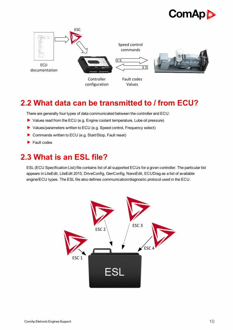
2 Principle of ECU supportSince the engines with electronic fuel injection became commonly used, ComAp has introduced a convenientsolution for monitoring andmanagement of such engines based on existing controllers InteliLite and InteliGen.These used to be fixed programmed and dedicated to a specific engine type, ECU or communication protocol. Aseparatemodule – I-CB (Communication Bridge) – was designed to interface InteliSys controller and ECUunique for its hardware or software features (e.g. communication speed).
Due to great development on the side of the enginemanufacturers regarding electronic equipment and amountof transmitted data from the ECU/engine, ComAp had to react promptly and launched new system of ECUsupport in the controllers. This new approach described below was started by the InteliDrive DCU controller.Later on it was adopted by the InteliLite controller (since version 2.0) and nowadays is integrated into all ComApcontrollers.
The new way of ECU support provides above all an easy and fast way how to integrate a new type of ECU.Although the enginemanufacturers often declare that the unit provides standard J1939 communication, afterdeeper analysis many of them appear to use proprietary data frames. Therefore ComAp controllers are simplyreconfigurable for such specific units using an external file – Engine Specific Code (ESC) – which contains allnecessary information about transmitted values, commands and diagnostic messages. The contents of this fileare downloaded to the controller which can afterwards provide complete datamonitoring and engine control overthe CAN bus.
The above described procedure of implementation of an ECU support ensures easy to use and fastconfiguration however it doesn’t reduce the controller’s flexibility. The user should be aware that ComApprovides default configuration and the controller must be adapted and configured to particular application.Providing themost common adjustment doesn’t eliminate the need to thoroughly test the functionality of theinstalled controller in conjunction with the gen-set and other equipment and advice the end user about the way ofits operation.
Due to quick development in this area it is strongly recommended to check up ComApweb pages(www.comap.cz) for software and documentation updates ahead of carrying on with projects comprisingelectronic engines.
2.1 What must be done to support a new ECU?Let's say about units communicating over CAN bus and using J1939 protocol (we will leave out specific units -using RS232/RS485 or their own CAN bus lines, Modbus). As mentioned above we cannot rely on ECU briefspecification which states that the unit supports J1939 protocol but we have to study a comprehensivespecification describing all details of data communicated by the unit. Only then it is possible to create an ESCand test it with the engine. So the necessary steps are in brief:
Study ECU documentation
If the ECU is fully compatible with SAE J1939-71, an ESC for “Standard J1939 engine” can be used
If the ECU is sufficiently but not fully consistent with SAE J1939-71, a new ESC has be created in ComAp
The controller with new ESC has to be tested with the engine/ECU (without testing the functionality is onlytheoretical – operating conditions of ECUs can vary a lot (for example sequence of activating/deactivating ofECU inputs during starting/stopping of the engine))
ComApEletronicEnginesSupport 10
2.2 What data can be transmitted to / from ECU?There are generally four types of data communicated between the controller and ECU:
Values read from the ECU (e.g. Engine coolant temperature, Lube oil pressure)
Values/parameters written to ECU (e.g. Speed control, Frequency select)
Commands written to ECU (e.g. Start/Stop, Fault reset)
Fault codes
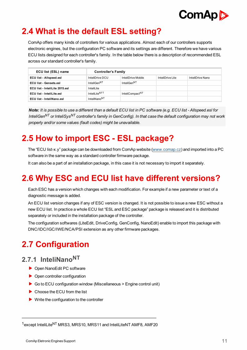
2.3 What is an ESL file?ESL (ECU Specification List) file contains list of all supported ECUs for a given controller. The particular listappears in LiteEdit, LiteEdit 2015, DriveConfig, GenConfig, NanoEdit, ECUDiag as a list of availableengine/ECU types. The ESL file also defines communication/diagnostic protocol used in the ECU.
ComApEletronicEnginesSupport 11
2.4 What is the default ESL setting?ComAp offers many kinds of controllers for various applications. Almost each of our controllers supportselectronic engines, but the configuration PC software and its settings are different. Therefore we have variousECU lists designed for each controller's family. In the table below there is a description of recommended ESLacross our standard controller's family.
ECU list (ESL) name Controller’s Family
ECU list - Allspeed.esl InteliDrive DCU InteliDriveMobile InteliDrive Lite InteliDrive Nano
ECU list - Gensets.esl InteliGenNT InteliGenNT
ECU list - InteliLite 2015.esl InteliLite
ECU list - InteliLite.esl InteliLiteNT1 InteliCompactNT
ECU list - InteliNano.esl InteliNanoNT
Note: It is possible to use a different than a default ECU list in PC software (e.g. ECU list - Allspeed.esl forInteliGenNT or InteliSysNT controller's family in GenConfig). In that case the default configurationmay not workproperly and/or some values (fault codes) might be unavailable.
2.5 How to import ESC - ESL package?The “ECU list-x.y” package can be downloaded from ComApwebsite (www.comap.cz) and imported into a PCsoftware in the sameway as a standard controller firmware package.
It can also be a part of an installation package, in this case it is not necessary to import it separately.
2.6 Why ESC and ECU list have different versions?Each ESC has a version which changes with eachmodification. For example if a new parameter or text of adiagnostic message is added.
An ECU list version changes if any of ESC version is changed. It is not possible to issue a new ESC without anew ECU list. In practice a whole ECU list “ESL and ESC package” package is released and it is distributedseparately or included in the installation package of the controller.
The configuration softwares (LiteEdit, DriveConfig, GenConfig, NanoEdit) enable to import this package withDNC/IDC/IGC/IWE/NCA/PSI extension as any other firmware packages.
2.7 Configuration
2.7.1 InteliNanoNTOpenNanoEdit PC software
Open controller configuration
Go to ECU configuration window (Miscellaneous > Engine control unit)
Choose the ECU from the list
Write the configuration to the controller
1except InteliLiteNTMRS3, MRS10, MRS11 and InteliLiteNT AMF8, AMF20
ComApEletronicEnginesSupport 12
Note: InteliNanoNT controller does not provide configurable inputs/outputs for engine parameters orcommands. The parameters are fixed and cannot be changed.
Default parameters for ECU (J1939 only)
NO. ANAIN from the ECU BININ from the ECU ANAOUT to the ECU1 BINOUT to the ECU2
1 Engine speed Speed control Start / Stop command
2 Coolant Temperature Idle / Nominal command
3 OilPressure Frequency selection
4 Fuel Level
5 TotalEngine Hours
Speed controlInteliNanoNT is an easy to use AMF orMRS controller with no capability to speed variation. The requestedspeed or accelerator pedal position is steady based on the Nominal Frequency setpoint.
ANAOUT to the ECU
Nominal Frequency Requested Speed Accelerator Pedal Position
50Hz 1500RPM 50%
60Hz 1800RPM 50%
Note: The speed control over the CAN bus (J1939 protocol) has to be supported by the engine ECU. Without itsupporting ComAp controllers cannot adjust the engine speed.
2.7.2 InteliDrive NanoOpenDriveEdit PC software
Open controller configuration
Go to ECU configuration window (Miscellaneous > Engine control unit)
Choose the ECU from the list
Write the configuration to the controller
Note: InteliDrive Nano controller does not provide configurable inputs/outputs for engine parameters orcommands. The parameters are fixed and cannot be changed.
Default parameters for ECU (J1939 only)
NO. ANAIN from the ECU BININ from the ECU ANAOUT to the ECU3 BINOUT to the ECU4
1 Engine speed Speed control Start / Stop command
2 Coolant Temperature Idle / Nominal command
3 OilPressure Frequency selection
4 Fuel Level
5 TotalEngine Hours
1Depends on the ECU capability2Depends on the ECU capability3Depends on the ECU capability4Depends on the ECU capability
ComApEletronicEnginesSupport 13
Speed controlInteliNanoNT is an easy to use engine controller with a capability to speed variation. The requred speed is basedon the configuration and application. Please refer to controller manual for more information about.
Note: The speed control over the CAN bus (J1939 protocol) has to be supported by the engine ECU. Without itsupporting ComAp controllers cannot adjust the engine speed.
2.7.3 InteliLiteNT, InteliCompactNTNote: Controllers InteliLiteNTMRS3, InteliLiteNTMRS10, InteliLiteNTMRS11, InteliLiteNT AMF8, InteliLiteNT
AMF20 don’t support electronic engines (engines equipped with ECU).
Open LiteEdit PC software
Open controller configuration
Enter controller password (controller > enter password)
Open themodify window (controller > configuration > modify…)
Click on ECU icon Check the “electronic engine is connected” check button
Choose the ECU from the list below
Confirm OK
Write the configuration to the controller
Note: InteliLiteNT and InteliCompactNT controllers do not provide configurable inputs/outputs for engineparameters or commands. The parameters are fixed and cannot be changed.
Default parameters for ECU (J1939 only)
NO. ANAIN from the ECU BININ from the ECU ANAOUT to the ECU1 BINOUT to the ECU2
1 Engine speed Yellow Lamp Speed control Start / Stop command
2 FuelRate Red Lamp Idle / Nominal command
3 Coolant Temperature Wait to Start Lamp Frequency selection
4 Intake Temperature Tier4 information Tier4 control
5 OilPressure
6 Percent Load
7 Boost Pressure
8 TotalEngine Hours
9 Total FuelUsed
Speed controlInteliLiteNT is an easy to use AMF orMRS gen-set controller with a limited capability to speed variation. Therequired speed is calculated from ECU FreqSelect and ECU SpeedAdj setpoints.
InteliCompactNT is an easy to use parallel (SPtM orMINT) controller with a full capability to speed variation.The required is calculated from ECU FreqSelect and ECU SpeedAdj setpoints or based on load share or baseload demand.
1Depends on the ECU capability2Depends on the ECU capability
ComApEletronicEnginesSupport 14
ANAOUT to the ECU (ECU FreqSelect setpoint = PRIMARY (DEFAULT))
ECU SpeedAdj Requested Speed Accelerator Pedal Position
0% 1350RPM 0%
50% 1500RPM 50%
100% 1650RPM 1000%
ANAOUT to the ECU (ECU FreqSelect setpoint = SECONDARY)
ECU SpeedAdj Requested Speed Accelerator Pedal Position
0% 1620RPM 0%
50% 1800RPM 50%
100% 1980RPM 1000%
Note: The speed control over the CAN bus (J1939 protocol) has to be supported by the engine ECU. Without itsupporting ComAp controllers cannot adjust the engine speed.
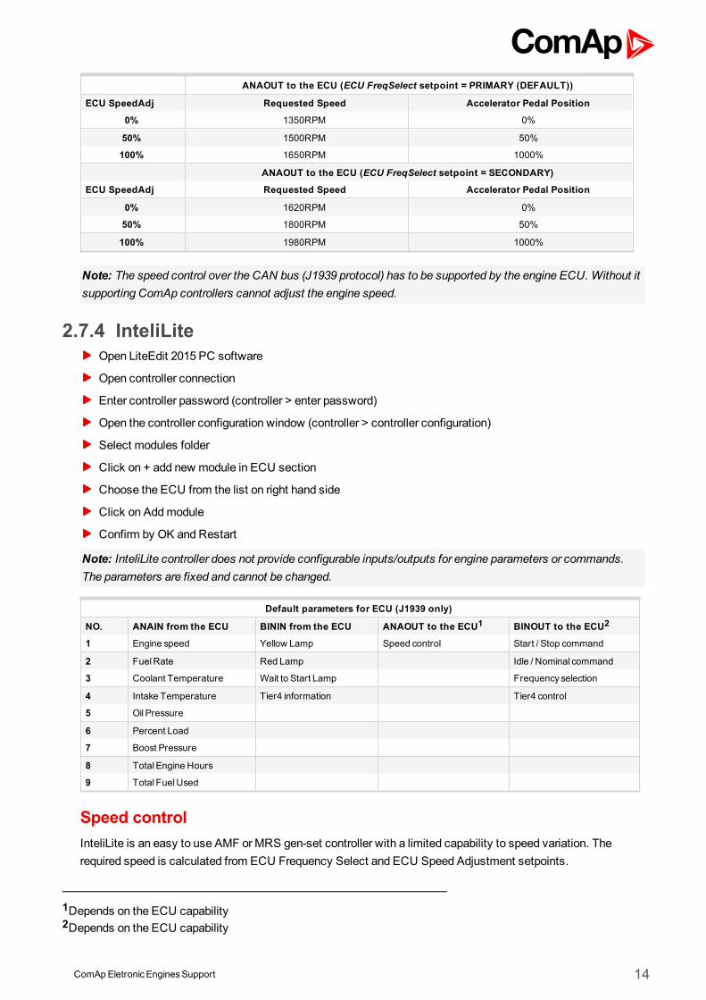
2.7.4 InteliLiteOpen LiteEdit 2015 PC software
Open controller connection
Enter controller password (controller > enter password)
Open the controller configuration window (controller > controller configuration)
Select modules folder
Click on + add new module in ECU section
Choose the ECU from the list on right hand side
Click on Addmodule
Confirm by OK and Restart
Note: InteliLite controller does not provide configurable inputs/outputs for engine parameters or commands.The parameters are fixed and cannot be changed.
Default parameters for ECU (J1939 only)
NO. ANAIN from the ECU BININ from the ECU ANAOUT to the ECU1 BINOUT to the ECU2
1 Engine speed Yellow Lamp Speed control Start / Stop command
2 FuelRate Red Lamp Idle / Nominal command
3 Coolant Temperature Wait to Start Lamp Frequency selection
4 Intake Temperature Tier4 information Tier4 control
5 OilPressure
6 Percent Load
7 Boost Pressure
8 TotalEngine Hours
9 Total FuelUsed
Speed controlInteliLite is an easy to use AMF orMRS gen-set controller with a limited capability to speed variation. Therequired speed is calculated from ECU Frequency Select and ECU Speed Adjustment setpoints.
1Depends on the ECU capability2Depends on the ECU capability
ComApEletronicEnginesSupport 15
ANAOUT to the ECU (ECU Frequency Select setpoint = PRIMARY (DEFAULT))
ECU SpeedAdj Requested Speed Accelerator Pedal Position
0% 1350RPM 0%
50% 1500RPM 50%
100% 1650RPM 1000%
ANAOUT to the ECU (ECU Frequency Select setpoint = SECONDARY)
ECU SpeedAdj Requested Speed Accelerator Pedal Position
0% 1620RPM 0%
50% 1800RPM 50%
100% 1980RPM 1000%
Note: The speed control over the CAN bus (J1939 protocol) has to be supported by the engine ECU. Without itsupporting ComAp controllers cannot adjust the engine speed.
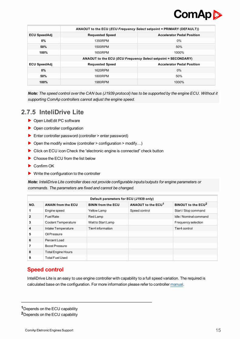
2.7.5 InteliDrive LiteOpen LiteEdit PC software
Open controller configuration
Enter controller password (controller > enter password)
Open themodify window (controller > configuration > modify…)
Click on ECU icon Check the “electronic engine is connected” check button
Choose the ECU from the list below
Confirm OK
Write the configuration to the controller
Note: InteliDrive Lite controller does not provide configurable inputs/outputs for engine parameters orcommands. The parameters are fixed and cannot be changed.
Default parameters for ECU (J1939 only)
NO. ANAIN from the ECU BININ from the ECU ANAOUT to the ECU1 BINOUT to the ECU2
1 Engine speed Yellow Lamp Speed control Start / Stop command
2 FuelRate Red Lamp Idle / Nominal command
3 Coolant Temperature Wait to Start Lamp Frequency selection
4 Intake Temperature Tier4 information Tier4 control
5 OilPressure
6 Percent Load
7 Boost Pressure
8 TotalEngine Hours
9 Total FuelUsed
Speed controlInteliDrive Lite is an easy to use engine controller with capability to a full speed variation. The required iscalculated base on the configuration. For more information please refer to controller manual.
1Depends on the ECU capability2Depends on the ECU capability
ComApEletronicEnginesSupport 16
ANAOUT to the ECU (ECU FreqSelect setpoint = PRIMARY (DEFAULT))
ECU SpeedAdj Requested Speed Accelerator Pedal Position
0% 1350RPM 0%
50% 1500RPM 50%
100% 1650RPM 1000%
ANAOUT to the ECU (ECU FreqSelect setpoint = SECONDARY)
ECU SpeedAdj Requested Speed Accelerator Pedal Position
0% 1620RPM 0%
50% 1800RPM 50%
100% 1980RPM 1000%
Note: The speed control over the CAN bus (J1939 protocol) has to be supported by the engine ECU. Without itsupporting ComAp controllers cannot adjust the engine speed.
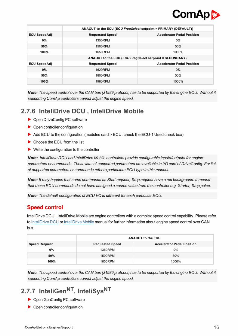
2.7.6 InteliDrive DCU , InteliDrive MobileOpenDriveConfig PC software
Open controller configuration
Add ECU to the configuration (modules card > ECU, check the ECU-1 Used check box)
Choose the ECU from the list
Write the configuration to the controller
Note: InteliDrive DCU and InteliDriveMobile controllers provide configurable inputs/outputs for engineparameters or commands. These lists of supported parameters are available in I/O card of DriveConfig. For listof supported parameters or commands refer to particulate ECU type in this manual.
Note: It may happen that some commands as Start request, Stop request have a red background. It meansthat these ECU commands do not have assigned a source value from the controller e.g. Starter, Stop pulse.
Note: The default configuration of ECU I/O is different for each particular ECU.
Speed controlInteliDrive DCU , InteliDriveMobile are engine controllers with a complex speed control capability. Please referto InteliDrive DCU or InteliDriveMobile manual for further information about engine speed control over CANbus.
ANAOUT to the ECU
Speed Request Requested Speed Accelerator Pedal Position
0% 1350RPM 0%
50% 1500RPM 50%
100% 1650RPM 1000%
Note: The speed control over the CAN bus (J1939 protocol) has to be supported by the engine ECU. Without itsupporting ComAp controllers cannot adjust the engine speed.
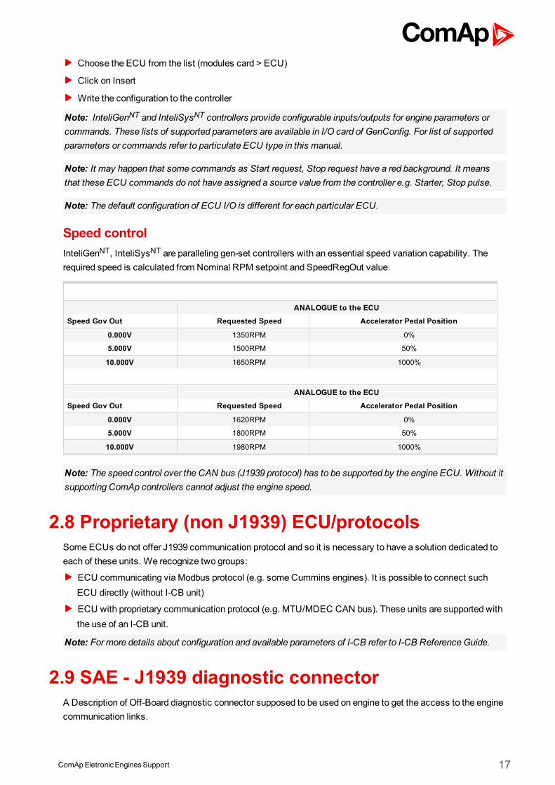
2.7.7 InteliGenNT, InteliSysNTOpenGenConfig PC software
Open controller configuration
ComApEletronicEnginesSupport 17
Choose the ECU from the list (modules card > ECU)
Click on Insert
Write the configuration to the controller
Note: InteliGenNT and InteliSysNT controllers provide configurable inputs/outputs for engine parameters orcommands. These lists of supported parameters are available in I/O card of GenConfig. For list of supportedparameters or commands refer to particulate ECU type in this manual.
Note: It may happen that some commands as Start request, Stop request have a red background. It meansthat these ECU commands do not have assigned a source value from the controller e.g. Starter, Stop pulse.
Note: The default configuration of ECU I/O is different for each particular ECU.
Speed controlInteliGenNT, InteliSysNT are paralleling gen-set controllers with an essential speed variation capability. Therequired speed is calculated from Nominal RPM setpoint and SpeedRegOut value.
ANALOGUE to the ECU
Speed Gov Out Requested Speed Accelerator Pedal Position
0.000V 1350RPM 0%
5.000V 1500RPM 50%
10.000V 1650RPM 1000%
ANALOGUE to the ECU
Speed Gov Out Requested Speed Accelerator Pedal Position
0.000V 1620RPM 0%
5.000V 1800RPM 50%
10.000V 1980RPM 1000%
Note: The speed control over the CAN bus (J1939 protocol) has to be supported by the engine ECU. Without itsupporting ComAp controllers cannot adjust the engine speed.
2.8 Proprietary (non J1939) ECU/protocolsSomeECUs do not offer J1939 communication protocol and so it is necessary to have a solution dedicated toeach of these units. We recognize two groups:
ECU communicating via Modbus protocol (e.g. someCummins engines). It is possible to connect suchECU directly (without I-CB unit)
ECU with proprietary communication protocol (e.g. MTU/MDEC CAN bus). These units are supported withthe use of an I-CB unit.
Note: Formore details about configuration and available parameters of I-CB refer to I-CB ReferenceGuide.
2.9 SAE - J1939 diagnostic connectorA Description of Off-Board diagnostic connector supposed to be used on engine to get the access to the enginecommunication links.
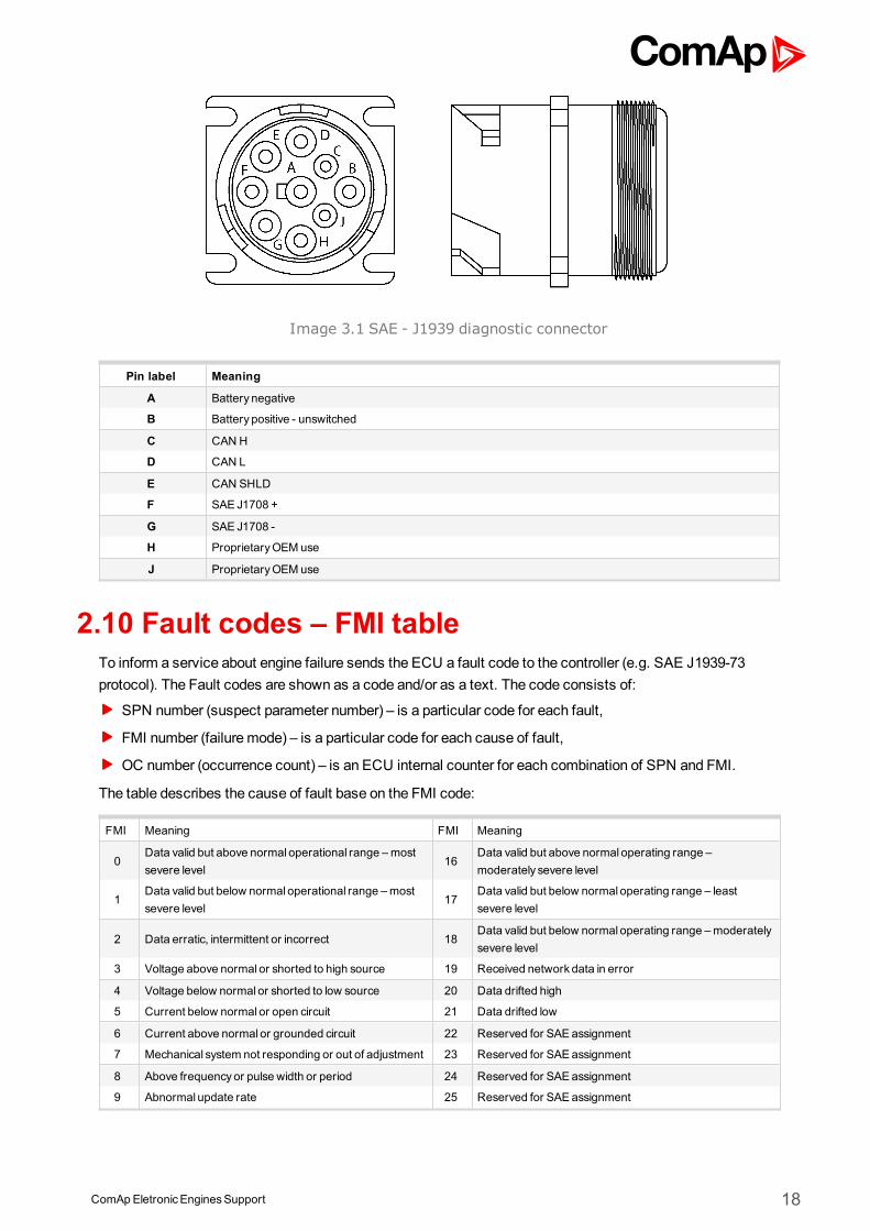
ComApEletronicEnginesSupport 18
Image 3.1 SAE - J1939 diagnostic connector
Pin label Meaning
A Battery negative
B Battery positive - unswitched
C CAN H
D CAN L
E CAN SHLD
F SAE J1708 +
G SAE J1708 -
H ProprietaryOEM use
J ProprietaryOEM use
2.10 Fault codes – FMI tableTo inform a service about engine failure sends the ECU a fault code to the controller (e.g. SAE J1939-73protocol). The Fault codes are shown as a code and/or as a text. The code consists of:
SPN number (suspect parameter number) – is a particular code for each fault,
FMI number (failure mode) – is a particular code for each cause of fault,
OC number (occurrence count) – is an ECU internal counter for each combination of SPN and FMI.
The table describes the cause of fault base on the FMI code:
FMI Meaning FMI Meaning
0Data valid but above normal operational range –mostsevere level
16Data valid but above normal operating range –moderately severe level
1Data valid but below normal operational range –mostsevere level
17Data valid but below normal operating range – leastsevere level
2 Data erratic, intermittent or incorrect 18Data valid but below normal operating range –moderatelysevere level
3 Voltage above normal or shorted to high source 19 Received network data in error
4 Voltage below normal or shorted to low source 20 Data drifted high
5 Current below normal or open circuit 21 Data drifted low
6 Current above normal or grounded circuit 22 Reserved for SAEassignment
7 Mechanical system not responding or out of adjustment 23 Reserved for SAEassignment
8 Above frequencyor pulse width or period 24 Reserved for SAEassignment
9 Abnormal update rate 25 Reserved for SAEassignment
ComApEletronicEnginesSupport 19
10 Abnormal rate of change 26 Reserved for SAEassignment
11 Root cause not known 27 Reserved for SAEassignment
12 Bad intelligent device or component 28 Reserved for SAEassignment
13 Out of calibration 29 Reserved for SAEassignment
14 Special instructions 30 Reserved for SAEassignment
15Data valid but above normal operating range – leastsevere level
31 Condition exists
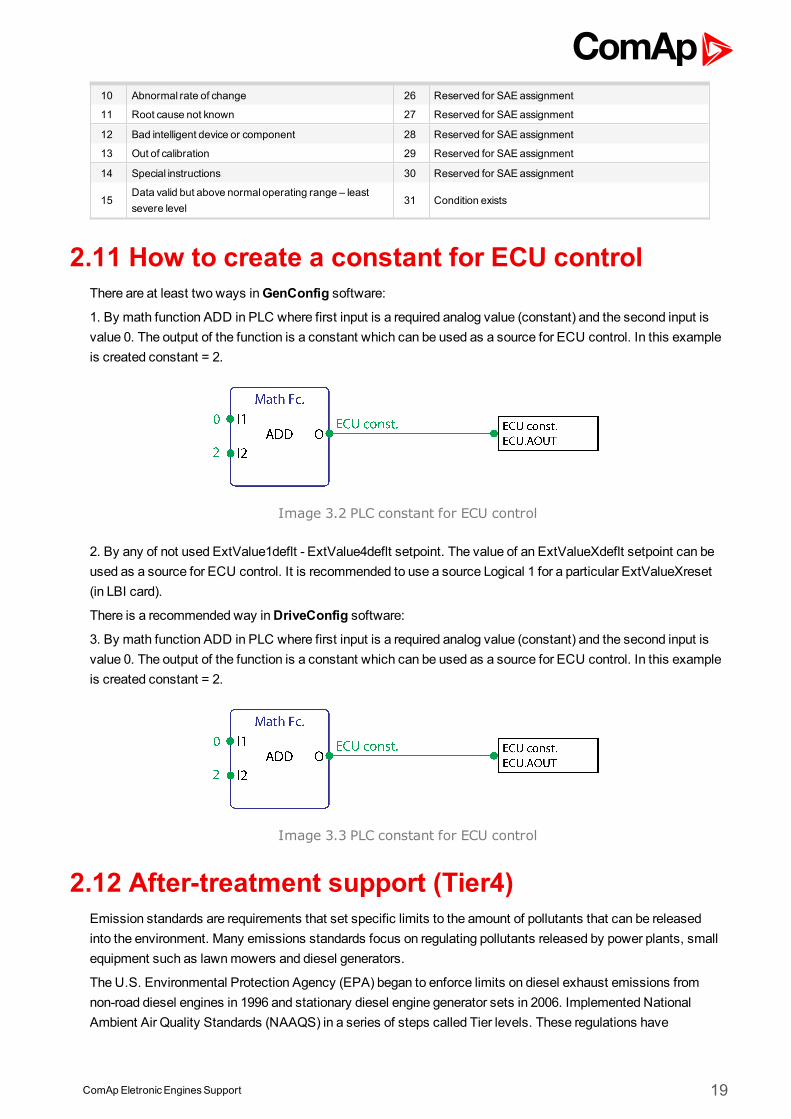
2.11 How to create a constant for ECU controlThere are at least two ways inGenConfig software:
1. By math function ADD in PLC where first input is a required analog value (constant) and the second input isvalue 0. The output of the function is a constant which can be used as a source for ECU control. In this exampleis created constant = 2.
Image 3.2 PLC constant for ECU control
2. By any of not used ExtValue1deflt - ExtValue4deflt setpoint. The value of an ExtValueXdeflt setpoint can beused as a source for ECU control. It is recommended to use a source Logical 1 for a particular ExtValueXreset(in LBI card).
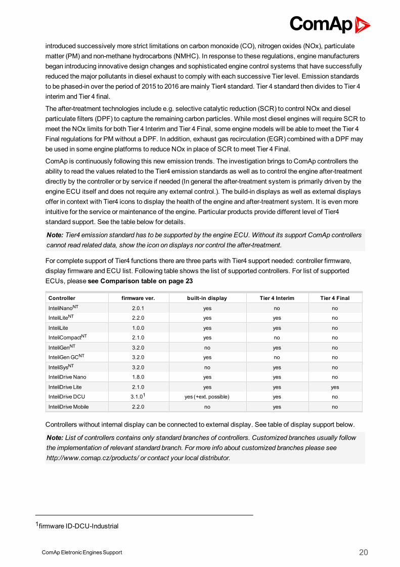
There is a recommended way inDriveConfig software:
3. By math function ADD in PLC where first input is a required analog value (constant) and the second input isvalue 0. The output of the function is a constant which can be used as a source for ECU control. In this exampleis created constant = 2.
Image 3.3 PLC constant for ECU control
2.12 After-treatment support (Tier4)Emission standards are requirements that set specific limits to the amount of pollutants that can be releasedinto the environment. Many emissions standards focus on regulating pollutants released by power plants, smallequipment such as lawnmowers and diesel generators.
The U.S. Environmental Protection Agency (EPA) began to enforce limits on diesel exhaust emissions fromnon-road diesel engines in 1996 and stationary diesel engine generator sets in 2006. Implemented NationalAmbient Air Quality Standards (NAAQS) in a series of steps called Tier levels. These regulations have
ComApEletronicEnginesSupport 20
introduced successively more strict limitations on carbonmonoxide (CO), nitrogen oxides (NOx), particulatematter (PM) and non-methane hydrocarbons (NMHC). In response to these regulations, enginemanufacturersbegan introducing innovative design changes and sophisticated engine control systems that have successfullyreduced themajor pollutants in diesel exhaust to comply with each successive Tier level. Emission standardsto be phased-in over the period of 2015 to 2016 aremainly Tier4 standard. Tier 4 standard then divides to Tier 4interim and Tier 4 final.
The after-treatment technologies include e.g. selective catalytic reduction (SCR) to control NOx and dieselparticulate filters (DPF) to capture the remaining carbon particles. While most diesel engines will require SCR tomeet the NOx limits for both Tier 4 Interim and Tier 4 Final, some enginemodels will be able tomeet the Tier 4Final regulations for PM without a DPF. In addition, exhaust gas recirculation (EGR) combined with a DPFmaybe used in some engine platforms to reduce NOx in place of SCR tomeet Tier 4 Final.
ComAp is continuously following this new emission trends. The investigation brings to ComAp controllers theability to read the values related to the Tier4 emission standards as well as to control the engine after-treatmentdirectly by the controller or by service if needed (In general the after-treatment system is primarily driven by theengine ECU itself and does not require any external control.). The build-in displays as well as external displaysoffer in context with Tier4 icons to display the health of the engine and after-treatment system. It is evenmoreintuitive for the service or maintenance of the engine. Particular products provide different level of Tier4standard support. See the table below for details.
Note: Tier4 emission standard has to be supported by the engine ECU. Without its support ComAp controllerscannot read related data, show the icon on displays nor control the after-treatment.
For complete support of Tier4 functions there are three parts with Tier4 support needed: controller firmware,display firmware and ECU list. Following table shows the list of supported controllers. For list of supportedECUs, please see Comparison table on page 23
Controller firmware ver. built-in display Tier 4 Interim Tier 4 Final
InteliNanoNT 2.0.1 yes no no
InteliLiteNT 2.2.0 yes yes no
InteliLite 1.0.0 yes yes no
InteliCompactNT 2.1.0 yes no no
InteliGenNT 3.2.0 no yes no
InteliGenGCNT 3.2.0 yes no no
InteliSysNT 3.2.0 no yes no
InteliDrive Nano 1.8.0 yes yes no
InteliDrive Lite 2.1.0 yes yes yes
InteliDrive DCU 3.1.01 yes (+ext. possible) yes no
InteliDriveMobile 2.2.0 no yes no
Controllers without internal display can be connected to external display. See table of display support below.
Note: List of controllers contains only standard branches of controllers. Customized branches usually followthe implementation of relevant standard branch. For more info about customized branches please seehttp://www.comap.cz/products/ or contact your local distributor.
1firmware ID-DCU-Industrial
ComApEletronicEnginesSupport 21
External display firmware ver. Tier 4 Interim Tier 4 Final
InteliVision 5 1.5.0 yes no
InteliVision 5 CAN 1.3.1 yes no
InteliVision 8 2.2.1 yes no
InteliVision 12 1.0.0 no no
Following table shows list of available icons (symbols) related to after-treatment support. There are oftenmoreinputs for control the icons than stated in SPN column, this table serves just as overview.
SPN Icon name Displayed Icon
3697 DieselParticulate Filter LampCommand
3702 DieselParticulate Filter Regeneration Inhibited
6915 SCR SystemCleaning LampCommand
3698 Exhaust SystemHigh Temperature LampCommand
5245 Fluid TankLow Level Indicator
1213 Malfunction Indicator Lamp (indicates that the active trouble code is emission-related)
624 Amber Warning Lamp
623 Red Stop Lamp
1081 EngineWait to start Lamp (Glow Lamp)
Note: Icons at buit-in displays are configured automatically. For further information about icon configuration forexternal displays, please refer to configuration PC softwaremanual (GenConfig, DriveConfig).
Beside icons there are few other signal that are crucial for Tier4Final support. These are summarized infollowing table.
ComApEletronicEnginesSupport 22
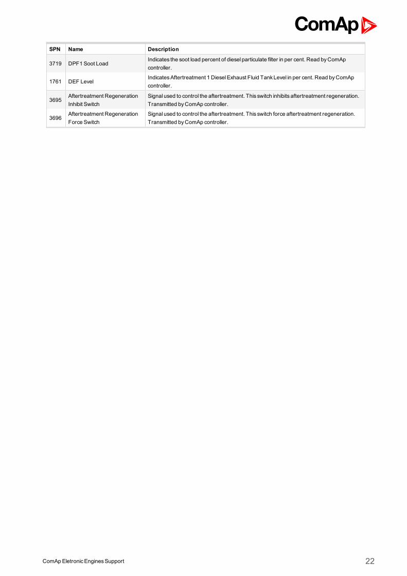
SPN Name Description
3719 DPF1 Soot LoadIndicates the soot load percent of diesel particulate filter in per cent. Read byComApcontroller.
1761 DEF LevelIndicatesAftertreatment 1 DieselExhaust Fluid TankLevel in per cent. Read byComApcontroller.
3695Aftertreatment RegenerationInhibit Switch
Signal used to control the aftertreatment. This switch inhibits aftertreatment regeneration.Transmitted byComAp controller.
3696Aftertreatment RegenerationForce Switch
Signal used to control the aftertreatment. This switch force aftertreatment regeneration.Transmitted byComAp controller.
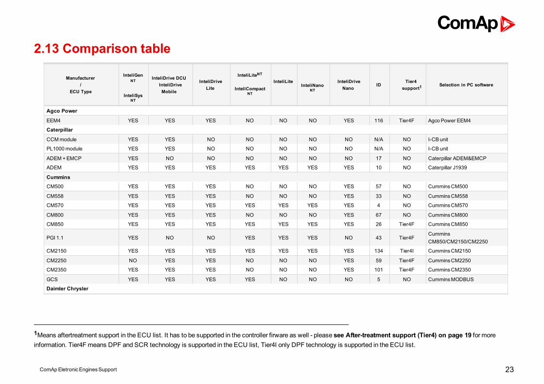
2.13 Comparison table
Manufacturer/
ECU Type
InteliGenNT
InteliSysNT
InteliDrive DCUInteliDriveMobile
InteliDriveLite
InteliLiteNT
InteliCompactNT
InteliLiteInteliNano
NT
InteliDriveNano
IDTier4
support1Selection in PC software
Agco Power
EEM4 YES YES YES NO NO NO YES 116 Tier4F Agco Power EEM4
Caterpillar
CCMmodule YES YES NO NO NO NO NO N/A NO I-CB unit
PL1000module YES YES NO NO NO NO NO N/A NO I-CB unit
ADEM+EMCP YES NO NO NO NO NO NO 17 NO Caterpillar ADEM&EMCP
ADEM YES YES YES YES YES YES YES 10 NO Caterpillar J1939
Cummins
CM500 YES YES YES NO NO NO YES 57 NO CumminsCM500
CM558 YES YES YES NO NO NO YES 33 NO CumminsCM558
CM570 YES YES YES YES YES YES YES 4 NO CumminsCM570
CM800 YES YES YES NO NO NO YES 67 NO CumminsCM800
CM850 YES YES YES YES YES YES YES 26 Tier4F CumminsCM850
PGI 1.1 YES NO NO YES YES YES NO 43 Tier4FCumminsCM850/CM2150/CM2250
CM2150 YES YES YES YES YES YES YES 134 Tier4I CumminsCM2150
CM2250 NO YES YES NO NO NO YES 59 Tier4F CumminsCM2250
CM2350 YES YES YES NO NO NO YES 101 Tier4F CumminsCM2350
GCS YES YES YES YES NO NO NO 5 NO CumminsMODBUS
Daimler Chrysler
1Means aftertreatment support in the ECU list. It has to be supported in the controller firware as well - please see After-treatment support (Tier4) on page 19 for moreinformation. Tier4F means DPF and SCR technology is supported in the ECU list, Tier4I only DPF technology is supported in the ECU list.
ComApEletronicEnginesSupport 23
Manufacturer/
ECU Type
InteliGenNT
InteliSysNT
InteliDrive DCUInteliDriveMobile
InteliDriveLite
InteliLiteNT
InteliCompactNT
InteliLiteInteliNano
NT
InteliDriveNano
IDTier4
support1Selection in PC software
ADM2 NO YES YES YES YES YES YES 24 NO Daimler Chrysler ADM2
ADM3 NO YES YES NO NO YES YES 42 NO Daimler Chrysler ADM3
Detroit Diesel
DDEC IV / V YES YES YES YES YES YES YES 9 NO DDCDDEC IV/V
Deutz
EMR2 YES YES YES YES YES YES YES 8 NO DeutzEMR2
EMR3 YES YES YES YES YES NO YES 25 NO DeutzEMR3
EMR4 YES YES YES YES YES YES YES 70 Tier4I DeutzEMR4
TEMEvolution YES YES NO NO NO NO NO N/A NO I-CB unit
Ford
E - control YES NO NO NO NO NO NO 95 NO Ford e-control
GM
MEFI4B / MEFI5B YES YES YES NO NO NO YES 34 NO GMMEFI4B / MEFI5B
MEFI6 YES YES YES YES YES YES YES 71 NO GMMEFI6
SECM YES YES YES YES YES YES YES 35 NO GMSECM
E - control YES YES YES YES YES YES YES 44 NO GMe-control
E - control LCI YES YES YES YES NO NO YES 58 NO GMe-control LCI
Isuzu
ECM YES YES YES YES YES YES YES 36 Tier4I Isuzu ECM
Iveco
EDC YES YES YES YES YES YES YES 14 Tier4I Iveco NEF &Cursor
EDC Tier3 YES YES YES YES YES YES YES 91 NO Iveco NEF &Cursor Tier3
ADEM III YES YES YES YES YES YES YES 28 NO Iveco Vector
1Means aftertreatment support in the ECU list. It has to be supported in the controller firware as well - please see After-treatment support (Tier4) on page 19 for moreinformation. Tier4F means DPF and SCR technology is supported in the ECU list, Tier4I only DPF technology is supported in the ECU list.
ComApEletronicEnginesSupport 24
Manufacturer/
ECU Type
InteliGenNT
InteliSysNT
InteliDrive DCUInteliDriveMobile
InteliDriveLite
InteliLiteNT
InteliCompactNT
InteliLiteInteliNano
NT
InteliDriveNano
IDTier4
support1Selection in PC software
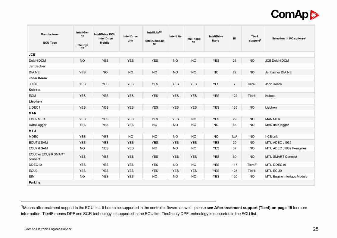
JCB
DelphiDCM NO YES YES YES NO NO YES 23 NO JCBDelphiDCM
Jenbacher
DIA.NE YES NO NO NO NO NO NO 22 NO Jenbacher DIA.NE
John Deere
JDEC YES YES YES YES YES YES YES 7 Tier4F John Deere
Kubota
ECM YES YES YES YES YES YES YES 122 Tier4I Kubota
Liebherr
LIDEC1 YES YES YES YES YES YES YES 135 NO Liebherr
MAN
EDC /MFR YES YES YES YES YES NO YES 29 NO MANMFR
Data Logger YES YES YES NO NO NO NO 56 NO MAN data logger
MTU
MDEC YES YES NO NO NO NO NO N/A NO I-CB unit
ECU7 &SAM YES YES YES YES YES YES YES 20 NO MTU ADEC J1939
ECU7&SAM NO YES YES NO NO NO YES 37 NO MTU ADEC J1939 P-engines
ECU8 or ECU9 &SMARTconnect
YES YES YES YES YES YES YES 60 NO MTU SMART Connect
DDEC10 YES YES YES YES NO NO YES 117 Tier4F MTU DDEC10
ECU9 YES YES YES YES YES YES YES 125 Tier4I MTU ECU9
EIM NO YES YES NO NO NO YES 120 NO MTU Engine InterfaceModule
Perkins
1Means aftertreatment support in the ECU list. It has to be supported in the controller firware as well - please see After-treatment support (Tier4) on page 19 for moreinformation. Tier4F means DPF and SCR technology is supported in the ECU list, Tier4I only DPF technology is supported in the ECU list.
ComApEletronicEnginesSupport 25

Manufacturer/
ECU Type
InteliGenNT
InteliSysNT
InteliDrive DCUInteliDriveMobile
InteliDriveLite
InteliLiteNT
InteliCompactNT
InteliLiteInteliNano
NT
InteliDriveNano
IDTier4
support1Selection in PC software
A4E2 or ECM YES YES YES YES YES YES YES 12 NO PerkinsECM
A4E2 or ECM NO NO NO YES YES YES NO 54 NO Perkins 1300
Scania
S6 YES YES YES YES YES YES YES 3/16 NO Scania S6 Singlespeed
S6 NO YES YES NO NO NO YES 6/11 NO Scania S6 Allspeed
S8 YES YES YES YES YES YES YES 68 Tier4I Scania S8 Singlespeed
S8 NO YES YES NO NO NO YES 69 Tier4I Scania S8 Allspeed
Sisu
EEM2 NO YES YES NO NO NO YES 19 NO Sisu EEM3Propulsion
EEM3 YES YES YES YES YES YES YES 18 NO Sisu EEM3Gen-set
Steyr
M1 NO YES YES NO NO NO YES 66 NO Steyr M1
VM
EDC YES YES YES YES YES YES YES 32/31 NO VM Industrial / VMMaine
Volvo
EDC3 / EMS1 / EMS2 YES YES YES YES YES YES YES 1 NO Volvo Singlespeed
EDC3 / EMS1 / EMS2 YES YES YES NO NO NO YES 2 NO Volvo Allspeed
EDC7 AllspeedKWP2000
NO YES NO NO NO NO NO 114 NO Volvo EDC7Allspeed KWP2000
Waukesha
1Means aftertreatment support in the ECU list. It has to be supported in the controller firware as well - please see After-treatment support (Tier4) on page 19 for moreinformation. Tier4F means DPF and SCR technology is supported in the ECU list, Tier4I only DPF technology is supported in the ECU list.
ComApEletronicEnginesSupport 26
Manufacturer/
ECU Type
InteliGenNT
InteliSysNT
InteliDrive DCUInteliDriveMobile
InteliDriveLite
InteliLiteNT
InteliCompactNT
InteliLiteInteliNano
NT
InteliDriveNano
IDTier4
support1Selection in PC software
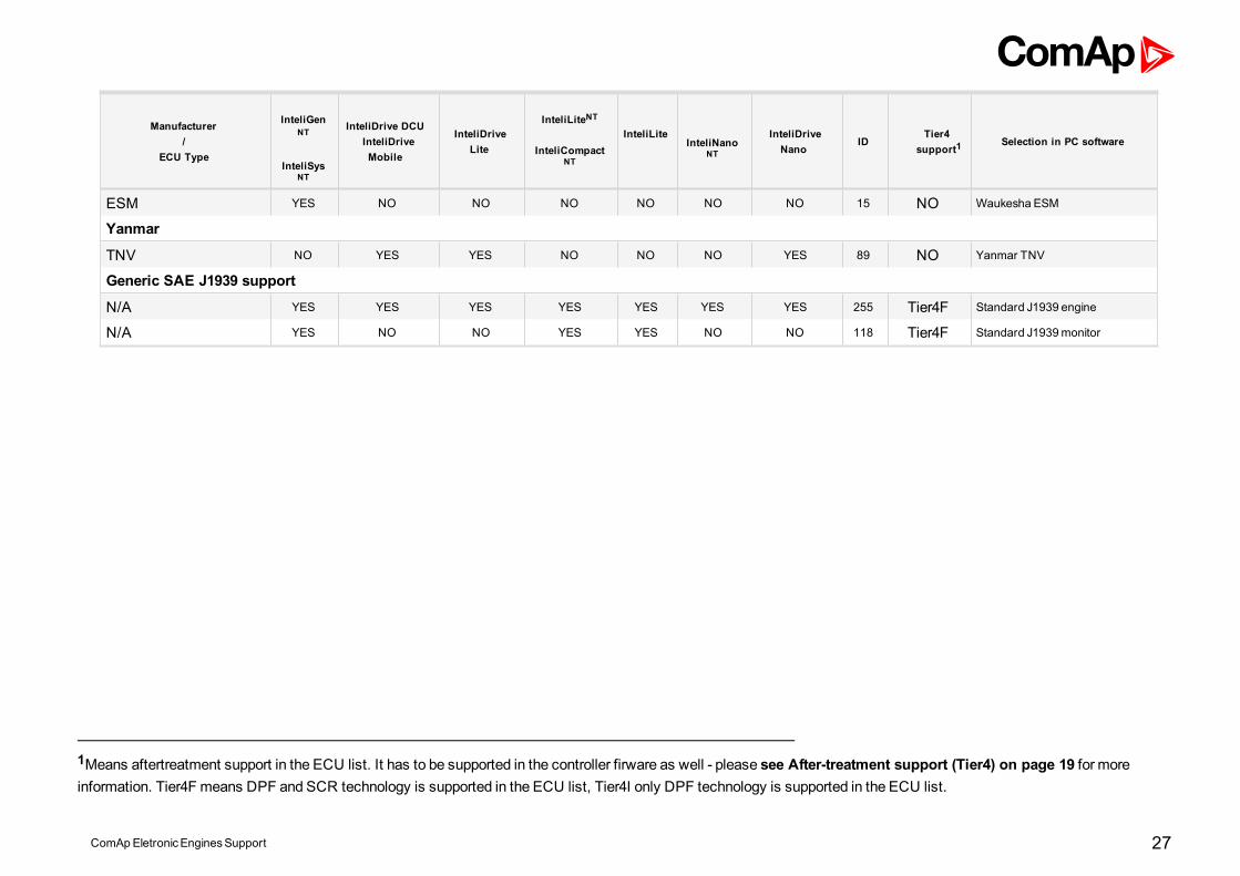
ESM YES NO NO NO NO NO NO 15 NO Waukesha ESM
Yanmar
TNV NO YES YES NO NO NO YES 89 NO Yanmar TNV
Generic SAE J1939 support
N/A YES YES YES YES YES YES YES 255 Tier4F Standard J1939 engine
N/A YES NO NO YES YES NO NO 118 Tier4F Standard J1939monitor
1Means aftertreatment support in the ECU list. It has to be supported in the controller firware as well - please see After-treatment support (Tier4) on page 19 for moreinformation. Tier4F means DPF and SCR technology is supported in the ECU list, Tier4I only DPF technology is supported in the ECU list.
ComApEletronicEnginesSupport 27
ComApEletronicEnginesSupport 28
3 List of ECU3.1 Agco Power engines support 293.2 Caterpillar engines support 323.3 Cummins engines support 413.4 Daimler Chrysler engines support 683.5 Detroit Diesel engines support 733.6 Deutz engines support 783.7 Ford engines support 903.8 GM engines support 933.9 Isuzu engines support 1043.10 Iveco engines support 1083.11 JCB engines support 1173.12 GE Jenbacher engines support 1203.13 JohnDeere engines support 1233.14 Kubota engines support 1283.15 Liebherr engines support 1323.16MAN engines support 1353.17MTU engines support 1403.18 Perkins engines support 1653.19 Scania engines support 1743.20 SISU engines support 1923.21 Steyr engines support 1963.22 VM engines support 1983.23 Volvo engines support 2043.24Waukesha engines support 2153.25 Yanmar engines support 2193.26 Standard J1939 engines support 222
ComApEletronicEnginesSupport 29
3.1 Agco Power engines supportECU Type Engine type
EEM4 All Offroad, marine, land generating engines
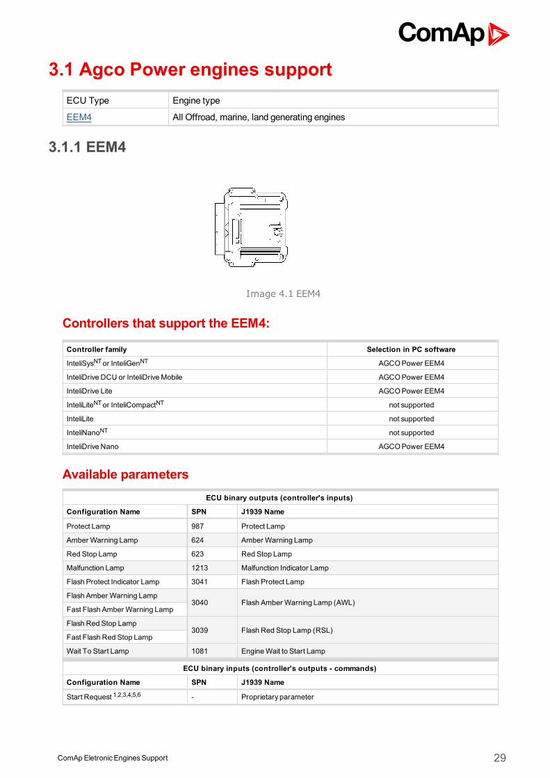
3.1.1 EEM4
Image 4.1 EEM4
Controllers that support the EEM4:
Controller family Selection in PC software
InteliSysNTor InteliGenNT AGCOPower EEM4
InteliDrive DCU or InteliDriveMobile AGCOPower EEM4
InteliDrive Lite AGCOPower EEM4
InteliLiteNTor InteliCompactNT not supported
InteliLite not supported
InteliNanoNT not supported
InteliDrive Nano AGCOPower EEM4
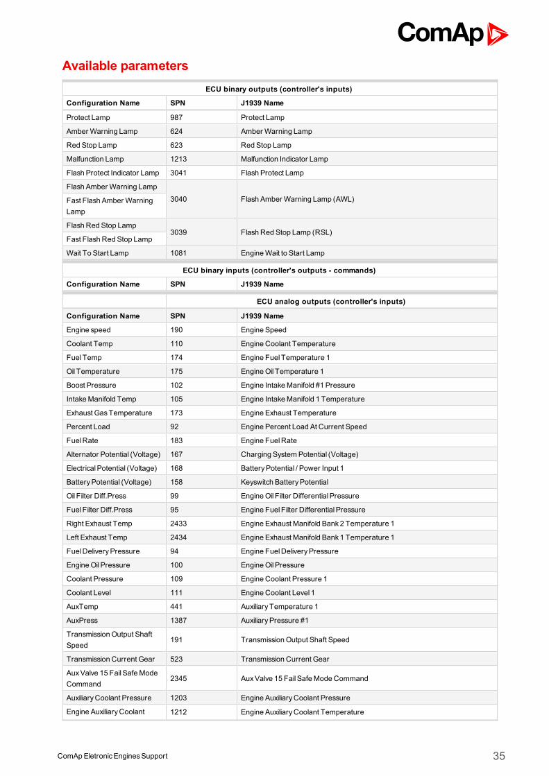
Available parametersECU binary outputs (controller's inputs)
Configuration Name SPN J1939 Name
Protect Lamp 987 Protect Lamp
Amber Warning Lamp 624 Amber Warning Lamp
Red Stop Lamp 623 Red Stop Lamp
Malfunction Lamp 1213 Malfunction Indicator Lamp
Flash Protect Indicator Lamp 3041 Flash Protect Lamp
Flash Amber Warning Lamp3040 Flash Amber Warning Lamp (AWL)
Fast Flash Amber Warning Lamp
Flash Red Stop Lamp3039 Flash Red Stop Lamp (RSL)
Fast Flash Red Stop Lamp
Wait To Start Lamp 1081 EngineWait to Start Lamp
ECU binary inputs (controller's outputs - commands)
Configuration Name SPN J1939 Name
Start Request 1,2,3,4,5,6 - Proprietary parameter
ComApEletronicEnginesSupport 30
Stop Request 1,2,3,4,5,6 - Proprietary parameter
ECU analog outputs (controller's inputs)
Configuration Name SPN J1939 Name
Engine speed 190 Engine Speed
Actual Torque 513 Actual Engine - Percent Torque
SCR Act. dosing reagent quality 4331 Aftertreatment 1 Diesel Exhaust Fluid Actual Dosing Quantity
SCR system state 4332 Aftertreatment 1 SCR System State
SCR Dosing Reagent Abs. Press 4334 Aftertreatment 1 Diesel Exhaust Fluid Doser Absolute Pressure
DEF Tank1 Level 1761 Aftertreatment 1 Diesel Exhaust Fluid Tank Level
Catalyst TankTemperature 3031 Aftertreatment 1 Diesel Exhaust Fluid Tank Temperature
Nominal Friction Torque 514 Nominal Friction - Percent Torque
Coolant Temp 110 Engine Coolant Temperature
Fuel Temp 174 Engine Fuel Temperature 1
EngineOil Temp 175 Engine Oil Temperature 1
Ambient Air Temperature 171 Ambient Air Temperature
Boost Pressure 102 Engine Intake Manifold #1 Pressure
IntakeManifold Temp 105 Engine Intake Manifold 1 Temperature
Percent Load 92 Engine Percent Load At Current Speed
FuelRate 183 Engine Fuel Rate
BatteryPotential (Voltage) 158 Keyswitch Battery Potential
DEF tank level lamp - Proprietary parameter
FuelDeliveryPressure 94 Engine Fuel Delivery Pressure
EngineOil Pressure 100 Engine Oil Pressure
ECU analog inputs (controller's outputs)
Configuration Name SPN J1939 Name
Requested speed 1,2,3,4,5,6 898 Engine Requested Speed/Speed Limit
Engine low idle switch 2883 Engine Alternate Low Idle Switch
Droop percentage request 2881 Engine Droop Accelerator 1 Select
Engine high idle switch - Proprietary parameter
Alternative low idle selection 2891 Engine Alternate Low Idle Select State
Alternative high idle selection - Proprietary parameter
Supported parameter by the controllers configured byNanoEdit, DriveEdit or LiteEdit PC software:
1 - InteliLiteNT, 2 - InteliLite , 3 - InteliDrive Lite , 4 - InteliCompactNT, 5 - InteliNanoNT, 6 - InteliDrive Nano
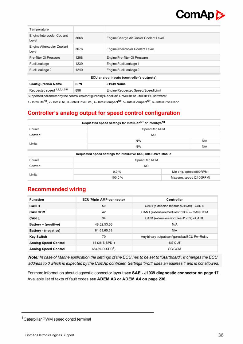
Controller’s analog output for speed control configurationRequested speed settings for InteliGenNT or InteliSysNT
Source SpeedReqRPM
Convert NO
LimitsN/A N/A
N/A N/A
Requested speed settings for InteliDrive DCU, InteliDrive Mobile
Source SpeedReqRPM
Convert NO
Limits0.0% Min eng. speed (800RPM)
100.0% Maxeng. speed (2100RPM)
ComApEletronicEnginesSupport 31
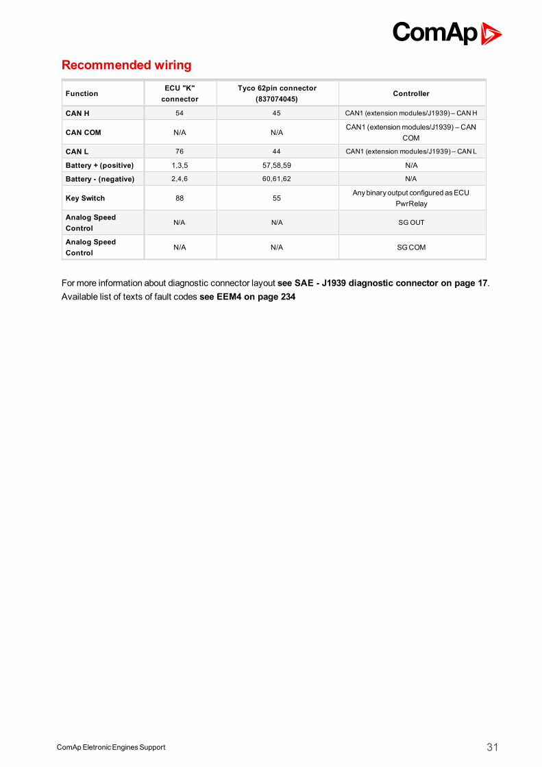
Recommended wiring
FunctionECU "K"connector
Tyco 62pin connector(837074045)
Controller
CAN H 54 45 CAN1 (extension modules/J1939) – CANH
CAN COM N/A N/ACAN1 (extensionmodules/J1939) – CAN
COM
CAN L 76 44 CAN1 (extension modules/J1939) – CANL
Battery + (positive) 1,3,5 57,58,59 N/A
Battery - (negative) 2,4,6 60,61,62 N/A
Key Switch 88 55Anybinary output configured asECU
PwrRelay
Analog SpeedControl
N/A N/A SG OUT
Analog SpeedControl
N/A N/A SGCOM
Formore information about diagnostic connector layout see SAE - J1939 diagnostic connector on page 17.Available list of texts of fault codes see EEM4 on page 234
ComApEletronicEnginesSupport 32
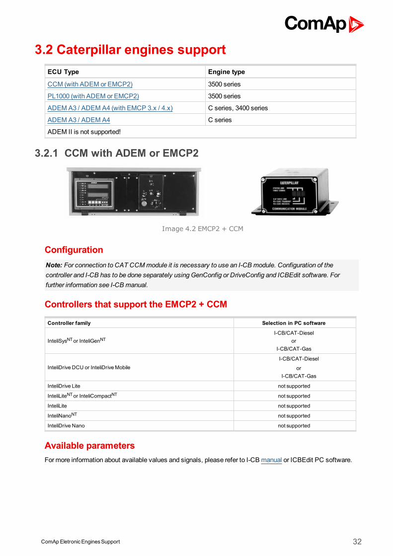
3.2 Caterpillar engines supportECU Type Engine type
CCM (with ADEM or EMCP2) 3500 series
PL1000 (with ADEM or EMCP2) 3500 series
ADEM A3 / ADEM A4 (with EMCP 3.x / 4.x) C series, 3400 series
ADEM A3 / ADEM A4 C series
ADEM II is not supported!
3.2.1 CCM with ADEM or EMCP2
Image 4.2 EMCP2 + CCM
ConfigurationNote: For connection to CAT CCMmodule it is necessary to use an I-CB module. Configuration of thecontroller and I-CB has to be done separately using GenConfig or DriveConfig and ICBEdit software. Forfurther information see I-CB manual.
Controllers that support the EMCP2 + CCM
Controller family Selection in PC software
InteliSysNTor InteliGenNTI-CB/CAT-Diesel
orI-CB/CAT-Gas
InteliDrive DCU or InteliDriveMobileI-CB/CAT-Diesel
orI-CB/CAT-Gas
InteliDrive Lite not supported
InteliLiteNTor InteliCompactNT not supported
InteliLite not supported
InteliNanoNT not supported
InteliDrive Nano not supported
Available parametersFormore information about available values and signals, please refer to I-CB manual or ICBEdit PC software.
ComApEletronicEnginesSupport 33
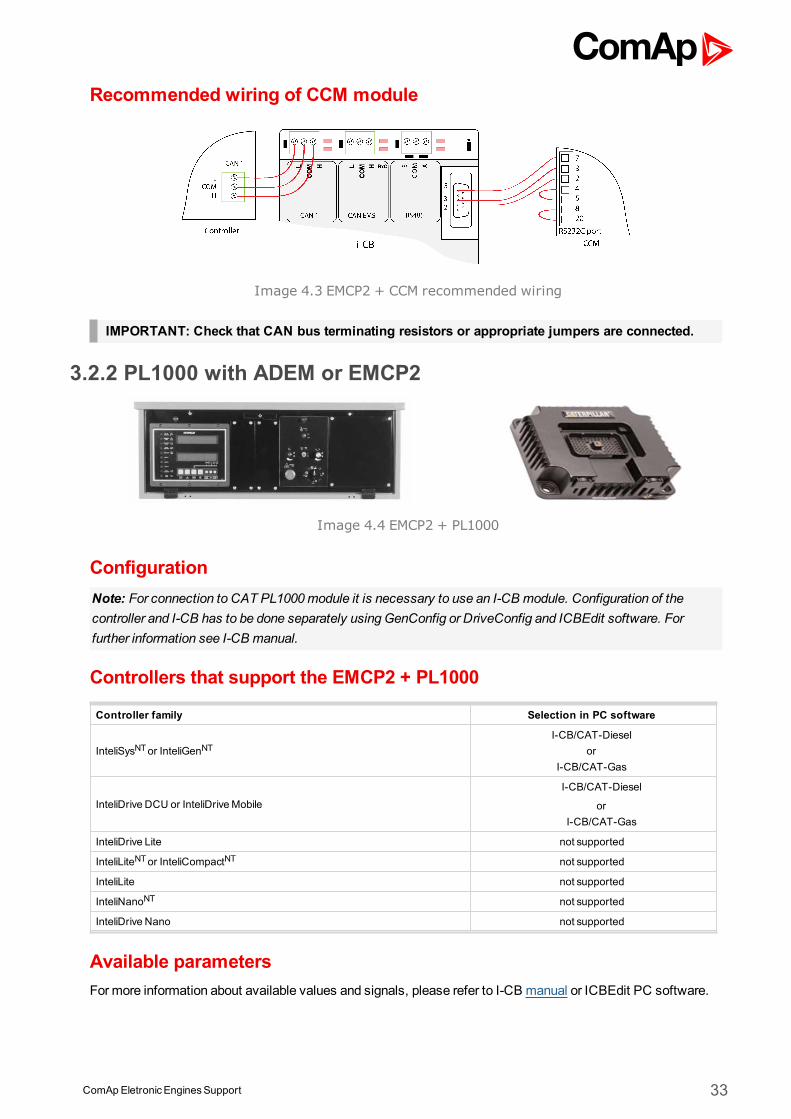
Recommended wiring of CCM module
Image 4.3 EMCP2 + CCM recommended wiring
IMPORTANT: Check that CAN bus terminating resistors or appropriate jumpers are connected.
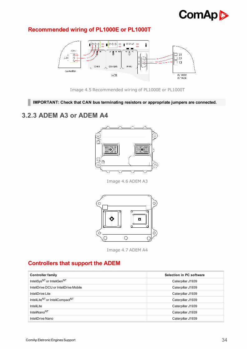
3.2.2 PL1000 with ADEM or EMCP2
Image 4.4 EMCP2 + PL1000
ConfigurationNote: For connection to CAT PL1000module it is necessary to use an I-CB module. Configuration of thecontroller and I-CB has to be done separately using GenConfig or DriveConfig and ICBEdit software. Forfurther information see I-CB manual.
Controllers that support the EMCP2 + PL1000
Controller family Selection in PC software
InteliSysNTor InteliGenNTI-CB/CAT-Diesel
orI-CB/CAT-Gas
InteliDrive DCU or InteliDriveMobileI-CB/CAT-Diesel
orI-CB/CAT-Gas
InteliDrive Lite not supported
InteliLiteNTor InteliCompactNT not supported
InteliLite not supported
InteliNanoNT not supported
InteliDrive Nano not supported
Available parametersFormore information about available values and signals, please refer to I-CB manual or ICBEdit PC software.
ComApEletronicEnginesSupport 34
Recommended wiring of PL1000E or PL1000T
Image 4.5 Recommended wiring of PL1000E or PL1000T
IMPORTANT: Check that CAN bus terminating resistors or appropriate jumpers are connected.
3.2.3 ADEM A3 or ADEM A4
Image 4.6 ADEM A3
Image 4.7 ADEM A4
Controllers that support the ADEM
Controller family Selection in PC software
InteliSysNTor InteliGenNT Caterpillar J1939
InteliDrive DCU or InteliDriveMobile Caterpillar J1939
InteliDrive Lite Caterpillar J1939
InteliLiteNTor InteliCompactNT Caterpillar J1939
InteliLite Caterpillar J1939
InteliNanoNT Caterpillar J1939
InteliDrive Nano Caterpillar J1939
ComApEletronicEnginesSupport 35
Available parametersECU binary outputs (controller's inputs)
Configuration Name SPN J1939 Name
Protect Lamp 987 Protect Lamp
Amber Warning Lamp 624 Amber Warning Lamp
Red Stop Lamp 623 Red Stop Lamp
Malfunction Lamp 1213 Malfunction Indicator Lamp
Flash Protect Indicator Lamp 3041 Flash Protect Lamp
Flash Amber Warning Lamp
3040 Flash Amber Warning Lamp (AWL)Fast Flash Amber WarningLamp
Flash Red Stop Lamp3039 Flash Red Stop Lamp (RSL)
Fast Flash Red Stop Lamp
Wait To Start Lamp 1081 EngineWait to Start Lamp
ECU binary inputs (controller's outputs - commands)
Configuration Name SPN J1939 Name
ECU analog outputs (controller's inputs)
Configuration Name SPN J1939 Name
Engine speed 190 Engine Speed
Coolant Temp 110 Engine Coolant Temperature
Fuel Temp 174 Engine Fuel Temperature 1
Oil Temperature 175 EngineOil Temperature 1
Boost Pressure 102 Engine IntakeManifold #1 Pressure
IntakeManifold Temp 105 Engine IntakeManifold 1 Temperature
Exhaust GasTemperature 173 Engine Exhaust Temperature
Percent Load 92 Engine Percent Load At Current Speed
FuelRate 183 Engine FuelRate
Alternator Potential (Voltage) 167 Charging SystemPotential (Voltage)
ElectricalPotential (Voltage) 168 BatteryPotential / Power Input 1
BatteryPotential (Voltage) 158 Keyswitch BatteryPotential
Oil Filter Diff.Press 99 EngineOil Filter Differential Pressure
Fuel Filter Diff.Press 95 Engine Fuel Filter Differential Pressure
Right Exhaust Temp 2433 Engine Exhaust Manifold Bank2 Temperature 1
Left Exhaust Temp 2434 Engine Exhaust Manifold Bank1 Temperature 1
FuelDeliveryPressure 94 Engine FuelDeliveryPressure
EngineOil Pressure 100 EngineOil Pressure
Coolant Pressure 109 Engine Coolant Pressure 1
Coolant Level 111 Engine Coolant Level 1
AuxTemp 441 AuxiliaryTemperature 1
AuxPress 1387 AuxiliaryPressure #1
TransmissionOutput ShaftSpeed
191 TransmissionOutput Shaft Speed
Transmission Current Gear 523 Transmission Current Gear
AuxValve 15 Fail SafeModeCommand
2345 AuxValve 15 Fail SafeModeCommand
AuxiliaryCoolant Pressure 1203 Engine AuxiliaryCoolant Pressure
Engine AuxiliaryCoolant 1212 Engine AuxiliaryCoolant Temperature
ComApEletronicEnginesSupport 36
Temperature
Engine Intercooler CoolantLevel
3668 Engine Charge Air Cooler Coolant Level
Engine Aftercooler CoolantLeve
3676 Engine Aftercooler Coolant Level
Pre-filter Oil Pressure 1208 Engine Pre-filter Oil Pressure
Fuel Leakage 1239 Engine Fuel Leakage 1
Fuel Leakage 2 1240 Engine Fuel Leakage 2
ECU analog inputs (controller's outputs)
Configuration Name SPN J1939 Name
Requested speed 1,2,3,4,5,6 898 Engine Requested Speed/Speed Limit
Supported parameter by the controllers configured byNanoEdit, DriveEdit or LiteEdit PC software:
1 - InteliLiteNT, 2 - InteliLite , 3 - InteliDrive Lite , 4 - InteliCompactNT, 5 - InteliCompactNT, 6 - InteliDrive Nano
Controller’s analog output for speed control configurationRequested speed settings for InteliGenNT or InteliSysNT
Source SpeedReq RPM
Convert NO
LimitsN/A N/A
N/A N/A
Requested speed settings for InteliDrive DCU, InteliDrive Mobile
Source SpeedReq RPM
Convert NO
Limits0.0 % Min eng. speed (800RPM)
100.0 % Max eng. speed (2100RPM)
Recommended wiringFunction ECU 70pin AMP connector Controller
CAN H 50 CAN1 (extension modules/J1939) – CANH
CAN COM 42 CAN1 (extensionmodules/J1939) – CAN COM
CAN L 34 CAN1 (extension modules/J1939) – CANL
Battery + (positive) 48,52,53,55 N/A
Battery - (negative) 61,63,65,69 N/A
Key Switch 70 Anybinary output configured asECU PwrRelay
Analog Speed Control 66 (38-S-SPD1) SG OUT
Analog Speed Control 68 (39-D-SPD1) SGCOM
Note: In case of Marine application the settings of the ECU has to be set to “Startboard”. It changes the ECUaddress to 0 which is expected by the ComAp controller. Settings “Port” uses an address 1 and is not allowed.
Formore information about diagnostic connector layout see SAE - J1939 diagnostic connector on page 17.Available list of texts of fault codes see ADEM A3 or ADEM A4 on page 236.
1Caterpillar PWM speed contol terminal
ComApEletronicEnginesSupport 37
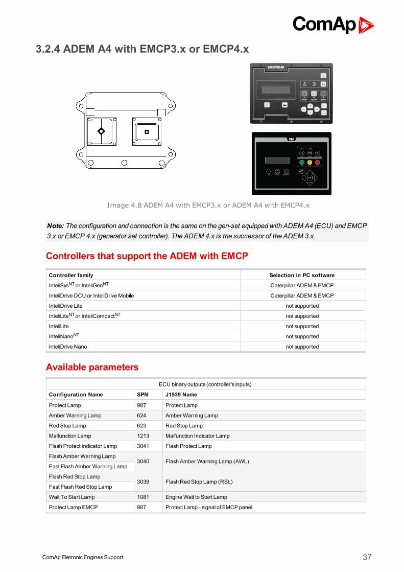
3.2.4 ADEM A4 with EMCP3.x or EMCP4.x
Image 4.8 ADEM A4 with EMCP3.x or ADEM A4 with EMCP4.x
Note: The configuration and connection is the same on the gen-set equipped with ADEM A4 (ECU) and EMCP3.x or EMCP 4.x (generator set controller). The ADEM 4.x is the successor of the ADEM 3.x.
Controllers that support the ADEM with EMCP
Controller family Selection in PC software
InteliSysNTor InteliGenNT Caterpillar ADEM&EMCP
InteliDrive DCU or InteliDriveMobile Caterpillar ADEM&EMCP
InteliDrive Lite not supported
InteliLiteNTor InteliCompactNT not supported
InteliLite not supported
InteliNanoNT not supported
InteliDrive Nano not supported
Available parametersECU binary outputs (controller's inputs)
Configuration Name SPN J1939 Name
Protect Lamp 987 Protect Lamp
Amber Warning Lamp 624 Amber Warning Lamp
Red Stop Lamp 623 Red Stop Lamp
Malfunction Lamp 1213 Malfunction Indicator Lamp
Flash Protect Indicator Lamp 3041 Flash Protect Lamp
Flash Amber Warning Lamp3040 Flash Amber Warning Lamp (AWL)
Fast Flash Amber Warning Lamp
Flash Red Stop Lamp3039 Flash Red Stop Lamp (RSL)
Fast Flash Red Stop Lamp
Wait To Start Lamp 1081 EngineWait to Start Lamp
Protect Lamp EMCP 987 Protect Lamp - signal of EMCPpanel
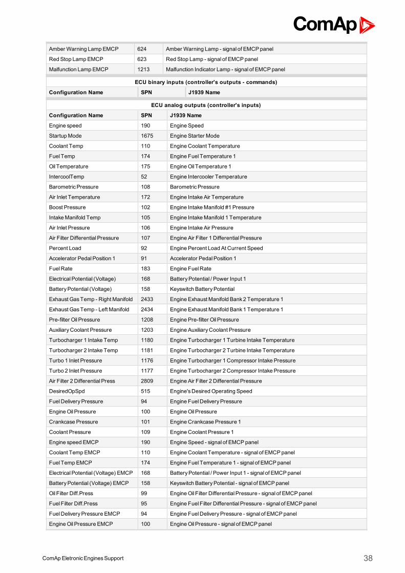
ComApEletronicEnginesSupport 38
Amber Warning LampEMCP 624 Amber Warning Lamp - signal of EMCPpanel
Red Stop LampEMCP 623 Red Stop Lamp - signal of EMCPpanel
Malfunction Lamp EMCP 1213 Malfunction Indicator Lamp - signal of EMCPpanel
ECU binary inputs (controller's outputs - commands)
Configuration Name SPN J1939 Name
ECU analog outputs (controller's inputs)
Configuration Name SPN J1939 Name
Engine speed 190 Engine Speed
StartupMode 1675 Engine Starter Mode
Coolant Temp 110 Engine Coolant Temperature
Fuel Temp 174 Engine Fuel Temperature 1
Oil Temperature 175 EngineOil Temperature 1
IntercoolTemp 52 Engine Intercooler Temperature
BarometricPressure 108 BarometricPressure
Air Inlet Temperature 172 Engine Intake Air Temperature
Boost Pressure 102 Engine IntakeManifold #1 Pressure
IntakeManifold Temp 105 Engine IntakeManifold 1 Temperature
Air Inlet Pressure 106 Engine Intake Air Pressure
Air Filter Differential Pressure 107 Engine Air Filter 1 Differential Pressure
Percent Load 92 Engine Percent Load At Current Speed
Accelerator PedalPosition 1 91 Accelerator PedalPosition 1
FuelRate 183 Engine FuelRate
ElectricalPotential (Voltage) 168 BatteryPotential / Power Input 1
BatteryPotential (Voltage) 158 Keyswitch BatteryPotential
Exhaust GasTemp - Right Manifold 2433 Engine Exhaust Manifold Bank2 Temperature 1
Exhaust GasTemp - Left Manifold 2434 Engine Exhaust Manifold Bank1 Temperature 1
Pre-filter Oil Pressure 1208 Engine Pre-filter Oil Pressure
AuxiliaryCoolant Pressure 1203 Engine AuxiliaryCoolant Pressure
Turbocharger 1 Intake Temp 1180 Engine Turbocharger 1 Turbine Intake Temperature
Turbocharger 2 Intake Temp 1181 Engine Turbocharger 2 Turbine Intake Temperature
Turbo 1 Inlet Pressure 1176 Engine Turbocharger 1 Compressor Intake Pressure
Turbo 2 Inlet Pressure 1177 Engine Turbocharger 2 Compressor Intake Pressure
Air Filter 2 Differential Press 2809 Engine Air Filter 2 Differential Pressure
DesiredOpSpd 515 Engine'sDesired Operating Speed
FuelDeliveryPressure 94 Engine FuelDeliveryPressure
EngineOil Pressure 100 EngineOil Pressure
Crankcase Pressure 101 Engine Crankcase Pressure 1
Coolant Pressure 109 Engine Coolant Pressure 1
Engine speed EMCP 190 Engine Speed - signal of EMCPpanel
Coolant Temp EMCP 110 Engine Coolant Temperature - signal of EMCPpanel
Fuel Temp EMCP 174 Engine Fuel Temperature 1 - signal of EMCPpanel
ElectricalPotential (Voltage) EMCP 168 BatteryPotential / Power Input 1 - signal of EMCPpanel
BatteryPotential (Voltage) EMCP 158 Keyswitch BatteryPotential - signal of EMCPpanel
Oil Filter Diff.Press 99 EngineOil Filter Differential Pressure - signal of EMCPpanel
Fuel Filter Diff.Press 95 Engine Fuel Filter Differential Pressure - signal of EMCPpanel
FuelDeliveryPressure EMCP 94 Engine FuelDeliveryPressure - signal of EMCPpanel
EngineOil Pressure EMCP 100 EngineOil Pressure - signal of EMCPpanel
ComApEletronicEnginesSupport 39
Throttle Position 51 Engine Throttle Valve 1 Position 1
Alternator Bearing 1 Temperature 1122 Engine Alternator Bearing 1 Temperature
Alternator Bearing 2 Temperature 1123 Engine Alternator Bearing 2 Temperature
Alternator Winding 1 Temperature 1124 Engine Alternator Winding 1 Temperature
Alternator Winding 2 Temperature 1125 Engine Alternator Winding 2 Temperature
Alternator Winding 3 Temperature 1126 Engine Alternator Winding 3 Temperature
Exhaust GasPort 1 Temp 1137 Engine Exhaust GasPort 1 Temperature
Exhaust GasPort 2 Temp 1138 Engine Exhaust GasPort 2 Temperature
Exhaust GasPort 3 Temp 1139 Engine Exhaust GasPort 3 Temperature
Exhaust GasPort 4 Temp 1140 Engine Exhaust GasPort 4 Temperature
Exhaust GasPort 5 Temp 1141 Engine Exhaust GasPort 5 Temperature
Exhaust GasPort 6 Temp 1142 Engine Exhaust GasPort 6 Temperature
Exhaust GasPort 7 Temp 1143 Engine Exhaust GasPort 7 Temperature
Exhaust GasPort 8 Temp 1144 Engine Exhaust GasPort 8 Temperature
Exhaust GasPort 9 Temp 1145 Engine Exhaust GasPort 9 Temperature
Exhaust GasPort 10 Temp 1146 Engine Exhaust GasPort 10 Temperature
Exhaust GasPort 11 Temp 1147 Engine Exhaust GasPort 11 Temperature
Exhaust GasPort 12 Temp 1148 Engine Exhaust GasPort 12 Temperature
Exhaust GasPort 13 Temp 1149 Engine Exhaust GasPort 13 Temperature
Exhaust GasPort 14 Temp 1150 Engine Exhaust GasPort 14 Temperature
Exhaust GasPort 15 Temp 1151 Engine Exhaust GasPort 15 Temperature
Exhaust GasPort 16 Temp 1152 Engine Exhaust GasPort 16 Temperature
GasSupplyPressure 159 EngineGaseousFuelSupplyPressure 1
Engine Intercooler Coolant Level 3668 Engine Charge Air Cooler Coolant Level
Fuel Filter Intake AbsPressure 5417 Engine Fuel Filter (Suction Side) Intake Absolute Pressure
Fuel Temperature 2 3468 Engine Fuel Temperature 2
ECU analog inputs (controller's outputs)
Configuration Name SPN J1939 Name
IMPORTANT: Speed control can be done by using PWM from the controller (SG interface) to theADEM. PWM rate for the controller has to be set to 500Hz. See the SpdGovPWM rate setpoint in theSync/Load ctrl group of setpoints. This feature has to be enabled in the ECU. Please contact yourlocal distributor to check it.Start/Stop command can be configured as Remote Start/Stop EMCP input. Use ECU PwrRelaycontroller output for this purpose.
Recommended wiringFunction ECU 70pin AMP connector Controller
CAN H 50 CAN1 (extension modules/J1939) – CANH
CAN COM 42 CAN1 (extensionmodules/J1939) – CAN COM
CAN L 34 CAN1 (extension modules/J1939) – CANL
Battery + (positive) 48,52,53,55 N/A
Battery - (negative) 61,63,65,69 N/A
ComApEletronicEnginesSupport 40
Key Switch 70 Anybinary output configured asECU PwrRelay
Analog Speed Control 66 (38-S-SPD1) SG OUT
Analog Speed Control 68 (39-D-SPD1) SGCOM
Formore information about diagnostic connector layout see SAE - J1939 diagnostic connector on page 17.Available list of texts of fault codes see Caterpillar ADEM A4 with EMCP3.x or ADEM A4 with EMCP4.xon page 237.
1Caterpillar PWM speed contol terminal
ComApEletronicEnginesSupport 41
3.3 Cummins engines supportECU Type Engine type
CM500 Industrial engines QSK19, QSK23, QSK45, QSK60, QSK78
CM558 Gas engines, QST30 (slave ECU)
CM570 (CM876) Tier2/Tier3 QSM11, QSX15, ISM 400, ISM 435
CM800 ISB, ISBe
PGI1.1(CM850,CM2150,CM2250)
Tier4i QSB7 andQSL9Tier 2 QSK50/60, QSK19, QSK38MCRSTier 3 QSB5, QSB7, QSL9, QSM11
CM2150 ISDe, ISLe, ISZ (ISX 13)
CM2350 Tier4 QSB6.7, QSL9, QSX15, QSF3.8, QSB4.5, QSG12
CM2250 Industrial engines (ISX, ISB series)
GCS Tier2 QSK23, QSK45/60/78, QST30
3.3.1 CM500
Image 4.9 CM500
Controllers that support the CM500
Controller family Selection in PC software
InteliSysNTor InteliGenNT CumminsCM500
InteliDrive DCU or InteliDriveMobile CumminsCM500
InteliDrive Lite CumminsCM500
InteliLiteNTor InteliCompactNT not supported
InteliLite not supported
InteliNanoNT not supported
InteliDrive Nano CumminsCM500
Available parametersECU binary outputs (controller's inputs)
Configuration Name SPN J1939 Name
Protect Lamp 987 Protect Lamp
ComApEletronicEnginesSupport 42
Amber Warning Lamp 624 Amber Warning Lamp
Red Stop Lamp 623 Red Stop Lamp
Malfunction Lamp 1213 Malfunction Indicator Lamp
Flash Protect Indicator Lamp 3041 Flash Protect Lamp
Flash Amber Warning Lamp
3040 Flash Amber Warning Lamp (AWL)Fast Flash Amber WarningLamp
Flash Red Stop Lamp3039 Flash Red Stop Lamp (RSL)
Fast Flash Red Stop Lamp
Wait To Start Lamp 1081 EngineWait to Start Lamp
AP low idle switch 558 Accelerator Pedal 1 Low Idle Switch
Water in Fuel 97 Water In Fuel Indicator 1
ECU binary inputs (controller's outputs - commands)
Configuration Name SPN J1939 Name
ECU analog outputs (controller's inputs)
Configuration Name SPN J1939 Name
APPosition 91 Accelerator PedalPosition 1
Percent Load 92 Engine Percent Load At Current Speed
Engine speed 190 Engine Speed
Actual Torque 513 ActualEngine - Percent Torque
Demand Torque 512 Driver'sDemand Engine - Percent Torque
Coolant Temp 110 Engine Coolant Temperature
Fuel Temp 174 Engine Fuel Temperature 1
Oil Temp 175 EngineOil Temperature 1
EngineOil Level 98 EngineOil Level
EngineOil Pressure 100 EngineOil Pressure
Coolant Pressure 109 Engine Coolant Pressure 1
FuelRate 183 Engine FuelRate
BarometricPressure 108 BarometricPressure
Air Inlet Temperature 172 Engine Intake Air Temperature
Boost Pressure 102 Engine IntakeManifold #1 Pressure
IntakeManifold Temp 105 Engine IntakeManifold 1 Temperature
ElectricalPotential (Voltage) 168 BatteryPotential / Power Input 1
ECU analog inputs (controller's outputs)
Configuration Name SPN J1939 Name
Requested speed 1,2,3,4,5,6 898 Engine Requested Speed/Speed Limit
Supported parameter by the controllers configured byNanoEdit, DriveEdit or LiteEdit PC software:
1 - InteliLiteNT, 2 - InteliLite , 3 - InteliDrive Lite , 4 - InteliCompactNT, 5 - InteliCompactNT, 6 - InteliDrive Nano
Controller’s analog output for speed control configurationRequested speed settings for InteliGenNT or InteliSysNT
Source SpeedReq RPM
Convert NO
LimitsN/A N/A
N/A N/A
ComApEletronicEnginesSupport 43
Requested speed settings for InteliDrive DCU, InteliDrive Mobile
Source SpeedReq RPM
Convert NO
Limits0.0 % Min eng. speed (800RPM)
100.0 % Max eng. speed (2100RPM)
Recommended wiringFunction ECU A2 connector Controller
CAN H 32 CAN1 (extension modules/J1939) – CANH
CAN COM N/A CAN1 (extensionmodules/J1939) – CAN COM
CAN L 33 CAN1 (extension modules/J1939) – CANL
Battery + (positive) 3,4,5 N/A
Battery - (negative) 7,8 N/A
Key Switch 10 Anybinary output configured asECU PwrRelay
Analog Speed Control N/A SG OUT
Analog Speed Control N/A SGCOM
Formore information about diagnostic connector layout see SAE - J1939 diagnostic connector on page 17.Available list of texts of fault codes see CM500 on page 238.
3.3.2 CM558
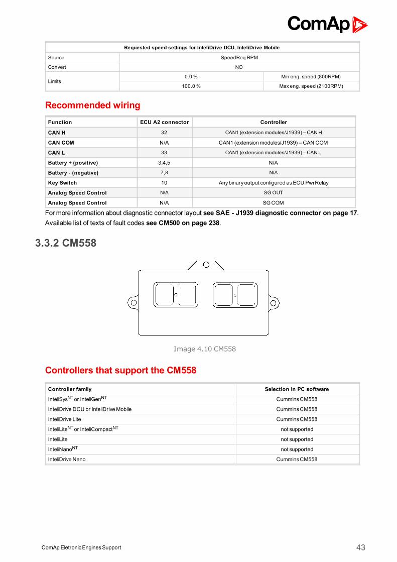
Image 4.10 CM558
Controllers that support the CM558
Controller family Selection in PC software
InteliSysNTor InteliGenNT CumminsCM558
InteliDrive DCU or InteliDriveMobile CumminsCM558
InteliDrive Lite CumminsCM558
InteliLiteNTor InteliCompactNT not supported
InteliLite not supported
InteliNanoNT not supported
InteliDrive Nano CumminsCM558
ComApEletronicEnginesSupport 44
Available parametersECU binary outputs (controller's inputs)
Configuration Name SPN J1939 Name
Protect Lamp 987 Protect Lamp
Amber Warning Lamp 624 Amber Warning Lamp
Red Stop Lamp 623 Red Stop Lamp
Malfunction Lamp 1213 Malfunction Indicator Lamp
Flash Protect Indicator Lamp 3041 Flash Protect Lamp
Flash Amber Warning Lamp
3040 Flash Amber Warning Lamp (AWL)Fast Flash Amber WarningLamp
Flash Red Stop Lamp3039 Flash Red Stop Lamp (RSL)
Fast Flash Red Stop Lamp
ECU binary inputs (controller's outputs - commands)
Configuration Name SPN J1939 Name
ECU analog outputs (controller's inputs)
Configuration Name SPN J1939 Name
Engine speed 190 Engine Speed
Percent Load 92 Engine Percent Load At Current Speed
Throttle Actuator 1Command
3464 Engine Throttle Actuator 1 ControlCommand
FuelActuator 1 Command 633 Engine FuelActuator 1 ControlCommand
Engine FuelShutoff 1 Control 632 Engine FuelShutoff 1 Control
Aftertreat1 ExhGasTemp 2 3249 Aftertreatment 1 Exhaust Temperature 2
Aftertreat1 ExhGasTemp 1 3241 Aftertreatment 1 Exhaust Temperature 1
IntakeManif. Absolute Press 3563 Engine IntakeManifold #1 Absolute Pressure
FuelValve 1 Position 1442 Engine FuelValve 1 Position
T-ECU 1136 Engine ECU Temperature
EngTemp 110 Engine Coolant Temperature
EngineOil Temp 175 EngineOil Temperature 1
BarometricPressure 108 BarometricPressure
IntakeManifold Temp 105 Engine IntakeManifold 1 Temperature
Air Intake Pressure 106 Engine Intake Air Pressure
Engine Throttle Position 51 Engine Throttle Valve 1 Position 1
BatteryPotential (Voltage) 168 BatteryPotential / Power Input 1
EngineOil Pressure 100 EngineOil Pressure
ECU analog inputs (controller's outputs)
Configuration Name SPN J1939 Name
Controller’s analog output for speed control configurationRequested speed settings for InteliGenNT or InteliSysNT
Source SpeedReq RPM
Convert NO
LimitsN/A N/A
N/A N/A
ComApEletronicEnginesSupport 45
Requested speed settings for InteliDrive DCU, InteliDrive Mobile
Source SpeedReq RPM
Convert NO
Limits0.0 % Min eng. speed (800RPM)
100.0 % Max eng. speed (2100RPM)
Recommended wiringNo documentation available so far!
For more information about diagnostic connector layout see SAE - J1939 diagnostic connector on page 17.Available list of texts of fault codes see CM558 on page 239.
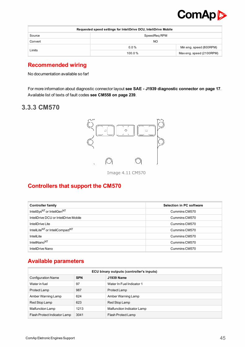
3.3.3 CM570
Image 4.11 CM570
Controllers that support the CM570
Controller family Selection in PC software
InteliSysNTor InteliGenNT CumminsCM570
InteliDrive DCU or InteliDriveMobile CumminsCM570
InteliDrive Lite CumminsCM570
InteliLiteNTor InteliCompactNT CumminsCM570
InteliLite CumminsCM570
InteliNanoNT CumminsCM570
InteliDrive Nano CumminsCM570
Available parametersECU binary outputs (controller's inputs)
Configuration Name SPN J1939 Name
Water in fuel 97 Water In Fuel Indicator 1
Protect Lamp 987 Protect Lamp
Amber Warning Lamp 624 Amber Warning Lamp
Red Stop Lamp 623 Red Stop Lamp
Malfunction Lamp 1213 Malfunction Indicator Lamp
Flash Protect Indicator Lamp 3041 Flash Protect Lamp
ComApEletronicEnginesSupport 46
Flash Amber Warning Lamp
3040 Flash Amber Warning Lamp (AWL)Fast Flash Amber WarningLamp
Flash Red Stop Lamp3039 Flash Red Stop Lamp (RSL)
Fast Flash Red Stop Lamp
PTOVarSpdSw 978 Engine Remote PTOGovernor Variable Speed Control Switch
Wait To Start Lamp 1081 EngineWait to Start Lamp
ECU binary inputs (controller's outputs - commands)
Configuration Name SPN J1939 Name
Run/Stop - Proprietary parameter
Idle/Rated - Proprietary parameter
EmergencyStop Indication - Proprietary parameter
Utility/IsochronousGainSelect
- Proprietary parameter
ECU analog outputs (controller's inputs)
Configuration Name SPN J1939 Name
Engine speed 190 Engine Speed
Coolant Temp 110 Engine Coolant Temperature
EngineOil Temp 175 EngineOil Temperature 1
Boost Pressure 102 Engine IntakeManifold #1 Pressure
IntakeManifold Temp 105 Engine IntakeManifold 1 Temperature
Percent Load 92 Engine Percent Load At Current Speed
FuelRate 183 Engine FuelRate
EngineOil Pressure 100 EngineOil Pressure
DesiredOpSpd 515 Engine'sDesired Operating Speed
BarometricPressure 108 BarometricPressure
ECU analog inputs (controller's outputs)
Configuration Name SPN J1939 Name
Speed BiasReference1,2,4,5,6 - Proprietary parameter
FrequencySelection 1,2,4,5,6 -
Proprietary parameter
0 - 50Hz
1 - 60Hz
2-5 -Reserved
6 - Error
7 -Do not care
Requested speed (TSC1) 3,6 898 Engine Requested Speed/Speed Limit
Supported parameter by the controllers configured byNanoEdit, DriveEdit or LiteEdit PC software:
1 - InteliLiteNT, 2 - InteliLite , 3 - InteliDrive Lite , 4 - InteliCompactNT, 5 - InteliCompactNT, 6 - InteliDrive Nano
Controller’s analog output for speed control configurationSpeed Bias Reference settings for InteliGenNT or InteliSysNT
Source SpdRegOut
Convert YES
Limits-10.000V -10%
+10.000V +10%
ComApEletronicEnginesSupport 47
Speed Bias Reference settings for InteliDrive DCU, InteliDrive Mobile
Source Speed Request
Convert YES
Limits0.0 % -10%
100.0 % +10%
Recommended wiringFunction ECU C-01 50pin connector Controller
CAN H 46 CAN1 (extension modules/J1939) – CANH
CAN COM 37 CAN1 (extensionmodules/J1939) – CAN COM
CAN L 36 CAN1 (extension modules/J1939) – CANL
Battery + (positive) 7,8,17,18,28 N/A
Battery - (negative) 29,30,39,40,50 N/A
Key Switch 38 Anybinary output configured asECU PwrRelay
Analog Speed Control N/A SG OUT
Analog Speed Control N/A SGCOM
Formore information about diagnostic connector layout see SAE - J1939 diagnostic connector on page 17.Available list of texts of fault codes see CM570 on page 240.
Table of tested ECU calibrationsEngine type ECU calibration
QSX15-G4 N11959.01
QSX15-G6 N 11960.01
QSX15-G7 N11961.01
QSX15-G8N 11962.01N 11962.05N12013.00
QSX15-G9 N11963.01
ISM L 21103.10
3.3.4 CM800
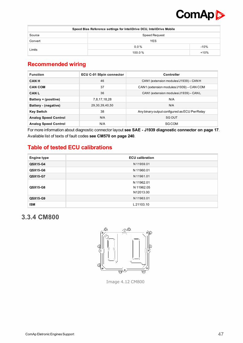
Image 4.12 CM800
ComApEletronicEnginesSupport 48
Controllers that support the CM800
Controller family Selection in PC software
InteliSysNTor InteliGenNT CumminsCM800
InteliDrive DCU or InteliDriveMobile CumminsCM800
InteliDrive Lite CumminsCM800
InteliLiteNTor InteliCompactNT not supported
InteliLite not supported
InteliNanoNT not supported
InteliDrive Nano CumminsCM800
Available parametersECU binary outputs (controller's inputs)
Configuration Name SPN J1939 Name
Protect Lamp 987 Protect Lamp
Amber Warning Lamp 624 Amber Warning Lamp
Red Stop Lamp 623 Red Stop Lamp
Malfunction Lamp 1213 Malfunction Indicator Lamp
Flash Protect Indicator Lamp 3041 Flash Protect Lamp
Flash Amber Warning Lamp
3040 Flash Amber Warning Lamp (AWL)Fast Flash Amber WarningLamp
Flash Red Stop Lamp3039 Flash Red Stop Lamp (RSL)
Fast Flash Red Stop Lamp
Water in fuel 97 Water In Fuel Indicator 1
PTOVarSpdSw 978 Engine Remote PTOGovernor Variable Speed Control Switch
ECU binary outputs (controller's inputs)
Configuration Name SPN J1939 Name
Run/Stop 1,2,3,4,5,6 - Proprietary parameter
ECU binary outputs (controller's inputs)
Configuration Name SPN J1939 Name
Engine speed 190 Engine Speed
Coolant Temp 110 Engine Coolant Temperature
EngineOil Temp 175 EngineOil Temperature 1
Boost Pressure 102 Engine IntakeManifold #1 Pressure
IntakeManifold Temp 105 Engine IntakeManifold 1 Temperature
Percent Load 92 Engine Percent Load At Current Speed
FuelRate 183 Engine FuelRate
EngineOil Pressure 100 EngineOil Pressure
DesiredOpSpd 515 Engine'sDesired Operating Speed
BarometricPressure 108 BarometricPressure
ECU analog inputs (controller's outputs)
Configuration Name SPN J1939 Name
Requested speed 1,2,3,4,5,6 898 Engine Requested Speed/Speed Limit
Supported parameter by the controllers configured byNanoEdit, DriveEdit or LiteEdit PC software:
1 - InteliLiteNT, 2 - InteliLite , 3 - InteliDrive Lite , 4 - InteliCompactNT, 5 - InteliCompactNT, 6 - InteliDrive Nano
ComApEletronicEnginesSupport 49
Controller’s analog output for speed control configurationRequested speed settings for InteliGenNT or InteliSysNT
Source SpeedReq RPM
Convert NO
LimitsN/A N/A
N/A N/A
Requested speed settings for InteliDrive DCU, InteliDrive Mobile
Source SpeedReq RPM
Convert NO
Limits0.0 % Min eng. speed (800RPM)
100.0 % Max eng. speed (2100RPM)
Recommended wiring
FunctionECU 40pin topconnector
3pin diagnosticconnector
Controller
CAN H 53 2 CAN1 (extension modules/J1939) – CANH
CAN COM 51 3CAN1 (extensionmodules/J1939) – CAN
COM
CAN L 52 1 CAN1 (extension modules/J1939) – CANL
Battery + (positive) 1,7,12,13 N/A N/A
Battery - (negative) 3,9,14,15 N/A N/A
Key Switch N/A N/AAnybinary output configured asECU
PwrRelay
Analog SpeedControl
N/A N/A SG OUT
Analog SpeedControl
N/A N/A SGCOM
Formore information about diagnostic connector layout see SAE - J1939 diagnostic connector on page 17.Available list of texts of fault codes see CM800 on page 241.
Table of tested ECU calibrationsEngine type ECU calibration
6ISBe 90132.05
3.3.5 CM850
Image 4.13 CM850
ComApEletronicEnginesSupport 50
Controllers that support the CM850
Controller family Selection in PC software
InteliSysNTor InteliGenNT CumminsCM850
InteliDrive DCU or InteliDriveMobile CumminsCM850
InteliDrive Lite CumminsCM850
InteliLiteNTor InteliCompactNT CumminsCM850
InteliLite CumminsCM850
InteliNanoNT CumminsCM850
InteliDrive Nano CumminsCM850
Available parametersECU binary outputs (controller's inputs)
Configuration Name SPN J1939 Name
Protect Lamp 987 Protect Lamp
Amber Warning Lamp 624 Amber Warning Lamp
Red Stop Lamp 623 Red Stop Lamp
Malfunction Lamp 1213 Malfunction Indicator Lamp
Flash Protect Indicator Lamp 3041 Flash Protect Lamp
Flash Amber Warning Lamp
3040 Flash Amber Warning Lamp (AWL)Fast Flash Amber WarningLamp
Flash Red Stop Lamp3039 Flash Red Stop Lamp (RSL)
Fast Flash Red Stop Lamp
Water in fuel 97 Water In Fuel Indicator 1
PTOVarSpdSw 978 Engine Remote PTOGovernor Variable Speed Control Switch
ECU binary outputs (controller's inputs)
Configuration Name SPN J1939 Name
Engine AuxiliaryShutdownSwitch 5,6
970 Engine AuxiliaryShutdown Switch
Run/Stop 1,2,3,4,5,6 - Proprietary parameter
Idle/Rated 1,2,3,4 - Proprietary parameter
ShutdownOverride CC 1,2,3,4 - Proprietary parameter
ECU binary outputs (controller's inputs)
Configuration Name SPN J1939 Name
Engine speed 190 Engine Speed
Exhaust GasTemperature -Right Manifold
2433 Engine Exhaust Manifold Bank2 Temperature 1
Exhaust GasTemperature -Left Manifold
2434 Engine Exhaust Manifold Bank1 Temperature 1
Pre-filter Oil Pressure 1208 Engine Pre-filter Oil Pressure
Coolant Temp 110 Engine Coolant Temperature
Fuel Temp 174 Engine Fuel Temperature 1
EngineOil Temp 175 EngineOil Temperature 1
TurboOil Temp 176 Engine Turbocharger Oil Temperature
Intercooler Temp 52 Engine Intercooler Temperature
Intercooler ThermostatOpening
1134 Engine Charge Air Cooler Thermostat Opening
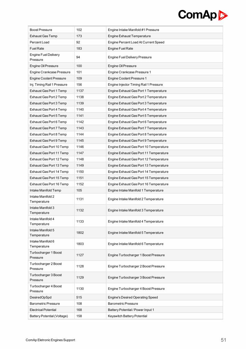
ComApEletronicEnginesSupport 51
Boost Pressure 102 Engine IntakeManifold #1 Pressure
Exhaust GasTemp 173 Engine Exhaust Temperature
Percent Load 92 Engine Percent Load At Current Speed
FuelRate 183 Engine FuelRate
Engine FuelDeliveryPressure
94 Engine FuelDeliveryPressure
EngineOil Pressure 100 EngineOil Pressure
Engine Crankcase Pressure 101 Engine Crankcase Pressure 1
Engine Coolant Pressure 109 Engine Coolant Pressure 1
Inj. Timing Rail 1 Pressure 156 Engine Injector Timing Rail 1 Pressure
Exhaust GasPort 1 Temp 1137 Engine Exhaust GasPort 1 Temperature
Exhaust GasPort 2 Temp 1138 Engine Exhaust GasPort 2 Temperature
Exhaust GasPort 3 Temp 1139 Engine Exhaust GasPort 3 Temperature
Exhaust GasPort 4 Temp 1140 Engine Exhaust GasPort 4 Temperature
Exhaust GasPort 5 Temp 1141 Engine Exhaust GasPort 5 Temperature
Exhaust GasPort 6 Temp 1142 Engine Exhaust GasPort 6 Temperature
Exhaust GasPort 7 Temp 1143 Engine Exhaust GasPort 7 Temperature
Exhaust GasPort 8 Temp 1144 Engine Exhaust GasPort 8 Temperature
Exhaust GasPort 9 Temp 1145 Engine Exhaust GasPort 9 Temperature
Exhaust GasPort 10 Temp 1146 Engine Exhaust GasPort 10 Temperature
Exhaust GasPort 11 Temp 1147 Engine Exhaust GasPort 11 Temperature
Exhaust GasPort 12 Temp 1148 Engine Exhaust GasPort 12 Temperature
Exhaust GasPort 13 Temp 1149 Engine Exhaust GasPort 13 Temperature
Exhaust GasPort 14 Temp 1150 Engine Exhaust GasPort 14 Temperature
Exhaust GasPort 15 Temp 1151 Engine Exhaust GasPort 15 Temperature
Exhaust GasPort 16 Temp 1152 Engine Exhaust GasPort 16 Temperature
IntakeManifold Temp 105 Engine IntakeManifold 1 Temperature
IntakeManifold 2Temperature
1131 Engine IntakeManifold 2 Temperature
IntakeManifold 3Temperature
1132 Engine IntakeManifold 3 Temperature
IntakeManifold 4Temperature
1133 Engine IntakeManifold 4 Temperature
IntakeManifold 5Temperature
1802 Engine IntakeManifold 5 Temperature
IntakeManifold 6Temperature
1803 Engine IntakeManifold 6 Temperature
Turbocharger 1 BoostPressure
1127 Engine Turbocharger 1 Boost Pressure
Turbocharger 2 BoostPressure
1128 Engine Turbocharger 2 Boost Pressure
Turbocharger 3 BoostPressure
1129 Engine Turbocharger 3 Boost Pressure
Turbocharger 4 BoostPressure
1130 Engine Turbocharger 4 Boost Pressure
DesiredOpSpd 515 Engine'sDesired Operating Speed
BarometricPressure 108 BarometricPressure
ElectricalPotential 168 BatteryPotential / Power Input 1
BatteryPotential (Voltage) 158 Keyswitch BatteryPotential
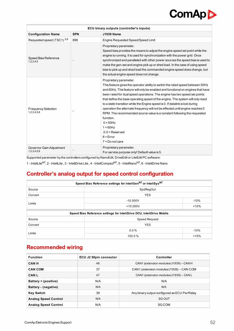
ComApEletronicEnginesSupport 52
ECU binary outputs (controller's inputs)
Configuration Name SPN J1939 Name
Requested speed (TSC1) 3,6 898 Engine Requested Speed/Speed Limit
Speed BiasReference1,2,3,4,5 -
Proprietary parameter.Speed biasprovides themeans to adjust the engine speed set point while theengine is running. It is used for synchronization with the power grid. Oncesynchronized and paralleled with other power sources the speed bias is used tomake the gen-set and engine pick up or shed load. In the case of using speedbias to pick up and shed load the commanded engine speed does change, butthe actual engine speed doesnot change.
FrequencySelection1,2,3,4,5,6 -
Proprietary parameter.This feature gives the operator ability to switch the rated speed between 50Hzand 60Hz. This feature will only be enabled and functional on engines that havebeen rated for dual speed operations. The engine has two speed set pointsthat define the base operating speed of the engine. The systemwill only reactto a state transition while the Engine speed is 0. If datalink is lost duringoperation the alternate frequencywill not be effected until engine reaches0RPM. The recommended source value is a constant following the requestedfunction.0 = 50Hz1 =60Hz2-5 =Reserved6 =Error7 =Do not care
Governor Gain Adjustment1,2,3,4,5,6 -
Proprietary parameter.For service purpose only! Default value is 5.
Supported parameter by the controllers configured byNanoEdit, DriveEdit or LiteEdit PC software:
1 - InteliLiteNT, 2 - InteliLite , 3 - InteliDrive Lite , 4 - InteliCompactNT, 5 - InteliNanoNT, 6 - InteliDrive Nano
Controller’s analog output for speed control configurationSpeed Bias Reference settings for InteliGenNT or InteliSysNT
Source SpdRegOut
Convert YES
Limits-10.000V -10%
+10.000V +10%
Speed Bias Reference settings for InteliDrive DCU, InteliDrive Mobile
Source Speed Request
Convert YES
Limits0.0 % -10%
100.0 % +10%
Recommended wiringFunction ECU J2 50pin connector Controller
CAN H 46 CAN1 (extension modules/J1939) – CANH
CAN COM 37 CAN1 (extensionmodules/J1939) – CAN COM
CAN L 47 CAN1 (extension modules/J1939) – CANL
Battery + (positive) N/A N/A
Battery - (negative) N/A N/A
Key Switch 39 Anybinary output configured asECU PwrRelay
Analog Speed Control N/A SG OUT
Analog Speed Control N/A SGCOM
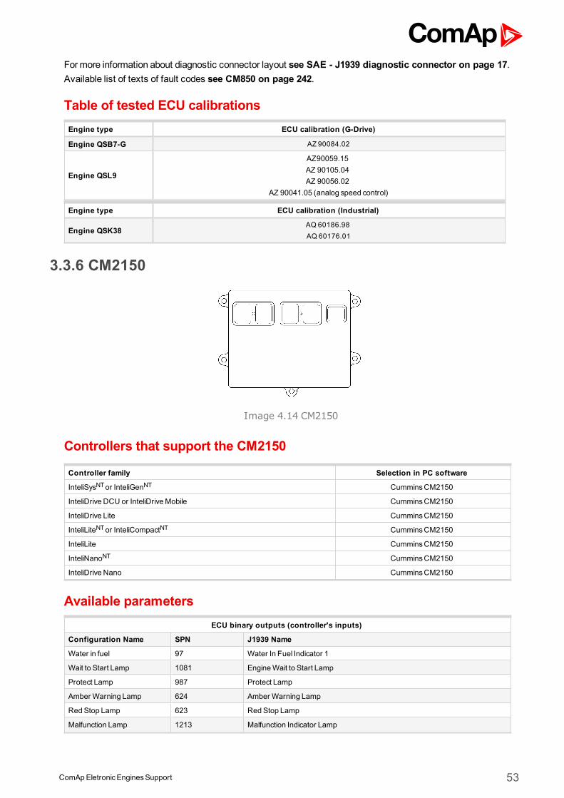
ComApEletronicEnginesSupport 53
Formore information about diagnostic connector layout see SAE - J1939 diagnostic connector on page 17.Available list of texts of fault codes see CM850 on page 242.
Table of tested ECU calibrationsEngine type ECU calibration (G-Drive)
Engine QSB7-G AZ 90084.02
Engine QSL9
AZ90059.15AZ 90105.04AZ 90056.02
AZ 90041.05 (analog speed control)
Engine type ECU calibration (Industrial)
Engine QSK38AQ 60186.98AQ 60176.01
3.3.6 CM2150
Image 4.14 CM2150
Controllers that support the CM2150
Controller family Selection in PC software
InteliSysNTor InteliGenNT CumminsCM2150
InteliDrive DCU or InteliDriveMobile CumminsCM2150
InteliDrive Lite CumminsCM2150
InteliLiteNTor InteliCompactNT CumminsCM2150
InteliLite CumminsCM2150
InteliNanoNT CumminsCM2150
InteliDrive Nano CumminsCM2150
Available parametersECU binary outputs (controller's inputs)
Configuration Name SPN J1939 Name
Water in fuel 97 Water In Fuel Indicator 1
Wait to Start Lamp 1081 EngineWait to Start Lamp
Protect Lamp 987 Protect Lamp
Amber Warning Lamp 624 Amber Warning Lamp
Red Stop Lamp 623 Red Stop Lamp
Malfunction Lamp 1213 Malfunction Indicator Lamp
ComApEletronicEnginesSupport 54
Flash Protect Indicator Lamp 3041 Flash Protect Lamp
Flash Amber Warning Lamp
3040 Flash Amber Warning Lamp (AWL)Fast Flash Amber WarningLamp
Flash Red Stop Lamp3039 Flash Red Stop Lamp (RSL)
Fast Flash Red Stop Lamp
AuxiliaryShutdown Sw 970 Engine Auxiliary Shutdown Switch
Engine Derate Switch 971 Engine Derate Switch
Remote Accelerator EnableSwitch
969 Remote Accelerator Enable Switch
ECU binary outputs (controller's inputs)
Configuration Name SPN J1939 Name
DPF Regeneration InhibitSwitch 1,2,3,4
3695 Aftertreatment Regeneration Inhibit Switch
DPF Regeneration ForceSwitch 1,2,3,4
3696 Aftertreatment Regeneration Force Switch
ECU binary outputs (controller's inputs)
Configuration Name SPN J1939 Name
FuelRate 183 Engine FuelRate
Throttle Position 51 Engine Throttle Valve 1 Position 1
BarometricPressure 108 BarometricPressure
Ambient Air Temperature 171 Ambient Air Temperature
Air Inlet Temperature 172 Engine Intake Air Temperature
Boost Pressure 102 Engine IntakeManifold #1 Pressure
IntakeManifold Temp 105 Engine IntakeManifold 1 Temperature
Air Inlet Pressure 106 Engine Intake Air Pressure
Air filter differential pressure 107 Engine Air Filter 1 Differential Pressure
Exhaust GasTemperature 173 Engine Exhaust Temperature
BatteryPotential (Voltage) 158 Keyswitch BatteryPotential
Coolant Temperature 110 Engine Coolant Temperature
Fuel Temperature 174 Engine Fuel Temperature 1
Oil Temp 175 EngineOil Temperature 1
Intercooler Temp 52 Engine Intercooler Temperature
FuelDeliveryPressure 94 Engine FuelDeliveryPressure
Oil Level 98 EngineOil Level
Oil Pressure 100 EngineOil Pressure
Crankcase Pressure 101 Engine Crankcase Pressure 1
Coolant Pressure 109 Engine Coolant Pressure 1
Coolant Level 111 Engine Coolant Level 1
Nominal Friction Torque 514 Nominal Friction - Percent Torque
Desired Operating Speed 515 Engine'sDesired Operating Speed
Rated Power 166 Engine Rated Power
DieselExhaust Fluid Tank1Level
1761 Aftertreatment 1 DieselExhaust Fluid TankLevel
DieselExhaust Fluid Tank1Temperature
3031 Aftertreatment 1 DieselExhaust Fluid TankTemperature
TorqueMode 899 Engine TorqueMode
Demand Torque 512 Driver'sDemand Engine - Percent Torque
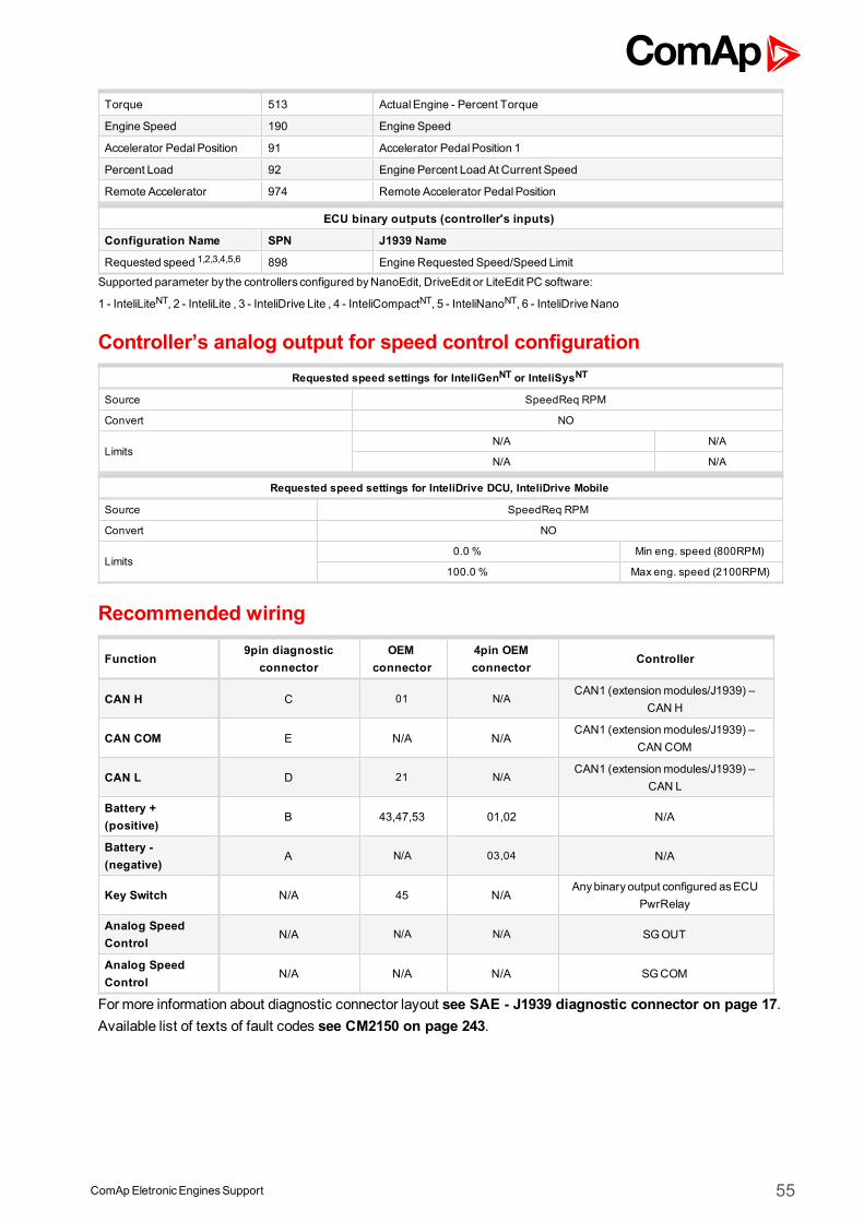
ComApEletronicEnginesSupport 55
Torque 513 ActualEngine - Percent Torque
Engine Speed 190 Engine Speed
Accelerator PedalPosition 91 Accelerator PedalPosition 1
Percent Load 92 Engine Percent Load At Current Speed
Remote Accelerator 974 Remote Accelerator PedalPosition
ECU binary outputs (controller's inputs)
Configuration Name SPN J1939 Name
Requested speed 1,2,3,4,5,6 898 Engine Requested Speed/Speed Limit
Supported parameter by the controllers configured byNanoEdit, DriveEdit or LiteEdit PC software:
1 - InteliLiteNT, 2 - InteliLite , 3 - InteliDrive Lite , 4 - InteliCompactNT, 5 - InteliNanoNT, 6 - InteliDrive Nano
Controller’s analog output for speed control configurationRequested speed settings for InteliGenNT or InteliSysNT
Source SpeedReq RPM
Convert NO
LimitsN/A N/A
N/A N/A
Requested speed settings for InteliDrive DCU, InteliDrive Mobile
Source SpeedReq RPM
Convert NO
Limits0.0 % Min eng. speed (800RPM)
100.0 % Max eng. speed (2100RPM)
Recommended wiring
Function9pin diagnostic
connectorOEM
connector4pin OEMconnector
Controller
CAN H C 01 N/ACAN1 (extensionmodules/J1939) –
CAN H
CAN COM E N/A N/ACAN1 (extensionmodules/J1939) –
CAN COM
CAN L D 21 N/ACAN1 (extensionmodules/J1939) –
CAN L
Battery +(positive)
B 43,47,53 01,02 N/A
Battery -(negative)
A N/A 03,04 N/A
Key Switch N/A 45 N/AAnybinary output configured asECU
PwrRelay
Analog SpeedControl
N/A N/A N/A SGOUT
Analog SpeedControl
N/A N/A N/A SGCOM
Formore information about diagnostic connector layout see SAE - J1939 diagnostic connector on page 17.Available list of texts of fault codes see CM2150 on page 243.
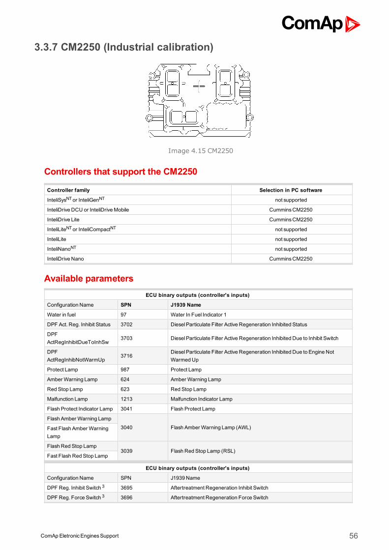
ComApEletronicEnginesSupport 56
3.3.7 CM2250 (Industrial calibration)
Image 4.15 CM2250
Controllers that support the CM2250
Controller family Selection in PC software
InteliSysNTor InteliGenNT not supported
InteliDrive DCU or InteliDriveMobile CumminsCM2250
InteliDrive Lite CumminsCM2250
InteliLiteNTor InteliCompactNT not supported
InteliLite not supported
InteliNanoNT not supported
InteliDrive Nano CumminsCM2250
Available parametersECU binary outputs (controller's inputs)
Configuration Name SPN J1939 Name
Water in fuel 97 Water In Fuel Indicator 1
DPF Act. Reg. Inhibit Status 3702 DieselParticulate Filter Active Regeneration Inhibited Status
DPFActRegInhibitDueToInhSw
3703 DieselParticulate Filter Active Regeneration Inhibited Due to Inhibit Switch
DPFActRegInhibNotWarmUp
3716DieselParticulate Filter Active Regeneration Inhibited Due to Engine NotWarmedUp
Protect Lamp 987 Protect Lamp
Amber Warning Lamp 624 Amber Warning Lamp
Red Stop Lamp 623 Red Stop Lamp
Malfunction Lamp 1213 Malfunction Indicator Lamp
Flash Protect Indicator Lamp 3041 Flash Protect Lamp
Flash Amber Warning Lamp
3040 Flash Amber Warning Lamp (AWL)Fast Flash Amber WarningLamp
Flash Red Stop Lamp3039 Flash Red Stop Lamp (RSL)
Fast Flash Red Stop Lamp
ECU binary outputs (controller's inputs)
Configuration Name SPN J1939 Name
DPF Reg. Inhibit Switch 3 3695 Aftertreatment Regeneration Inhibit Switch
DPF Reg. Force Switch 3 3696 Aftertreatment Regeneration Force Switch
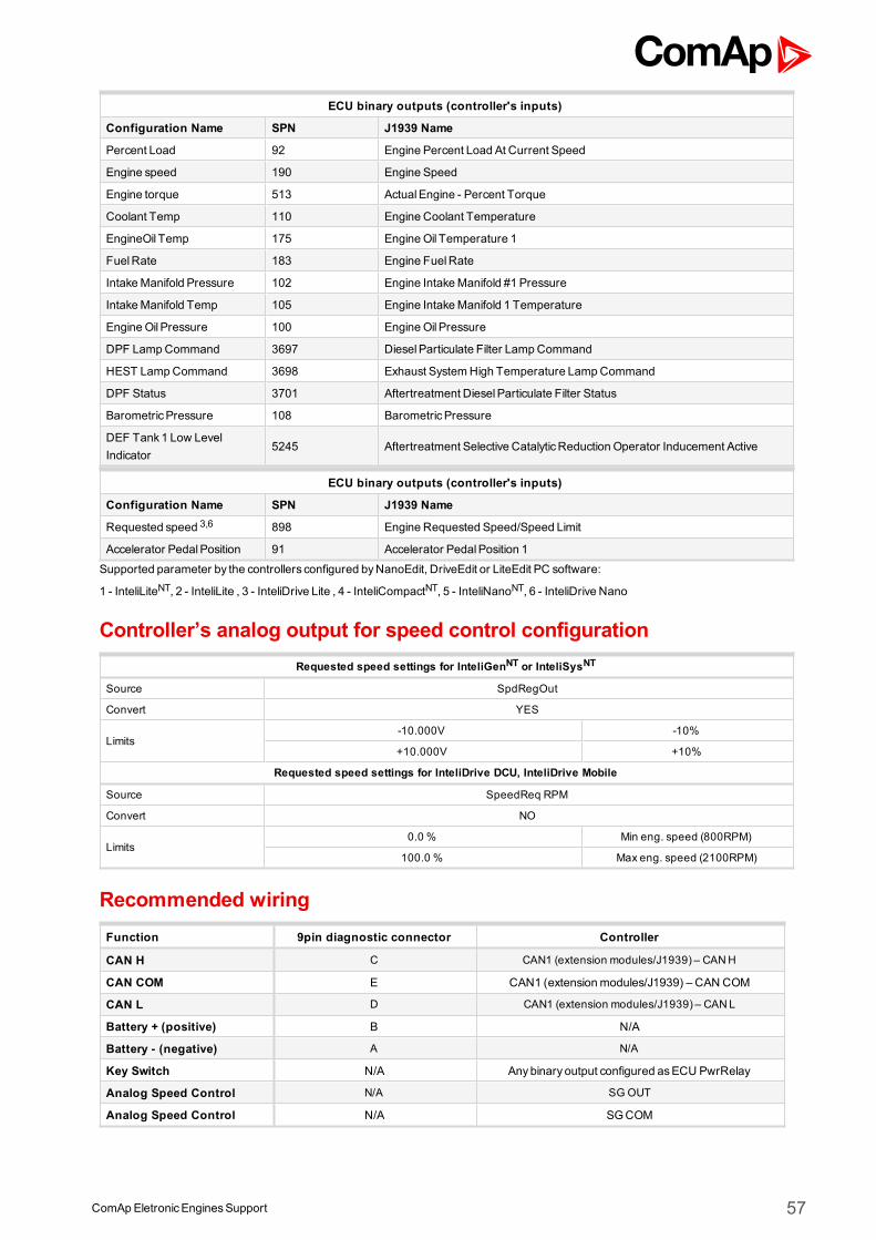
ComApEletronicEnginesSupport 57
ECU binary outputs (controller's inputs)
Configuration Name SPN J1939 Name
Percent Load 92 Engine Percent Load At Current Speed
Engine speed 190 Engine Speed
Engine torque 513 ActualEngine - Percent Torque
Coolant Temp 110 Engine Coolant Temperature
EngineOil Temp 175 EngineOil Temperature 1
FuelRate 183 Engine FuelRate
IntakeManifold Pressure 102 Engine IntakeManifold #1 Pressure
IntakeManifold Temp 105 Engine IntakeManifold 1 Temperature
EngineOil Pressure 100 EngineOil Pressure
DPF LampCommand 3697 DieselParticulate Filter LampCommand
HEST LampCommand 3698 Exhaust SystemHigh Temperature LampCommand
DPF Status 3701 Aftertreatment DieselParticulate Filter Status
BarometricPressure 108 BarometricPressure
DEF Tank1 Low LevelIndicator
5245 Aftertreatment Selective CatalyticReduction Operator Inducement Active
ECU binary outputs (controller's inputs)
Configuration Name SPN J1939 Name
Requested speed 3,6 898 Engine Requested Speed/Speed Limit
Accelerator PedalPosition 91 Accelerator PedalPosition 1
Supported parameter by the controllers configured byNanoEdit, DriveEdit or LiteEdit PC software:
1 - InteliLiteNT, 2 - InteliLite , 3 - InteliDrive Lite , 4 - InteliCompactNT, 5 - InteliNanoNT, 6 - InteliDrive Nano
Controller’s analog output for speed control configurationRequested speed settings for InteliGenNT or InteliSysNT
Source SpdRegOut
Convert YES
Limits-10.000V -10%
+10.000V +10%
Requested speed settings for InteliDrive DCU, InteliDrive Mobile
Source SpeedReq RPM
Convert NO
Limits0.0 % Min eng. speed (800RPM)
100.0 % Max eng. speed (2100RPM)
Recommended wiringFunction 9pin diagnostic connector Controller
CAN H C CAN1 (extension modules/J1939) – CANH
CAN COM E CAN1 (extensionmodules/J1939) – CAN COM
CAN L D CAN1 (extension modules/J1939) – CANL
Battery + (positive) B N/A
Battery - (negative) A N/A
Key Switch N/A Anybinary output configured asECU PwrRelay
Analog Speed Control N/A SG OUT
Analog Speed Control N/A SGCOM
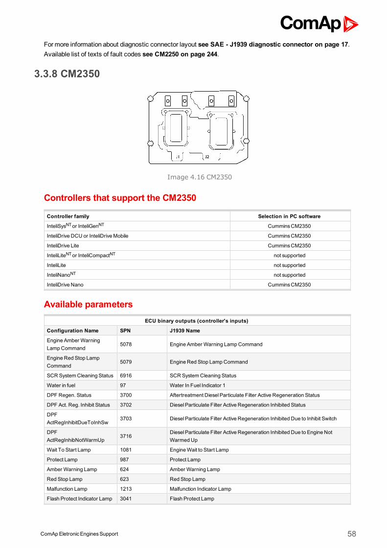
ComApEletronicEnginesSupport 58
Formore information about diagnostic connector layout see SAE - J1939 diagnostic connector on page 17.Available list of texts of fault codes see CM2250 on page 244.
3.3.8 CM2350
Image 4.16 CM2350
Controllers that support the CM2350
Controller family Selection in PC software
InteliSysNTor InteliGenNT CumminsCM2350
InteliDrive DCU or InteliDriveMobile CumminsCM2350
InteliDrive Lite CumminsCM2350
InteliLiteNTor InteliCompactNT not supported
InteliLite not supported
InteliNanoNT not supported
InteliDrive Nano CumminsCM2350
Available parametersECU binary outputs (controller's inputs)
Configuration Name SPN J1939 Name
Engine Amber WarningLampCommand
5078 Engine Amber Warning LampCommand
Engine Red Stop LampCommand
5079 Engine Red Stop LampCommand
SCR SystemCleaning Status 6916 SCR SystemCleaning Status
Water in fuel 97 Water In Fuel Indicator 1
DPF Regen. Status 3700 Aftertreatment DieselParticulate Filter Active Regeneration Status
DPF Act. Reg. Inhibit Status 3702 DieselParticulate Filter Active Regeneration Inhibited Status
DPFActRegInhibitDueToInhSw
3703 DieselParticulate Filter Active Regeneration Inhibited Due to Inhibit Switch
DPFActRegInhibNotWarmUp
3716DieselParticulate Filter Active Regeneration Inhibited Due to Engine NotWarmedUp
Wait To Start Lamp 1081 EngineWait to Start Lamp
Protect Lamp 987 Protect Lamp
Amber Warning Lamp 624 Amber Warning Lamp
Red Stop Lamp 623 Red Stop Lamp
Malfunction Lamp 1213 Malfunction Indicator Lamp
Flash Protect Indicator Lamp 3041 Flash Protect Lamp
ComApEletronicEnginesSupport 59
Flash Amber Warning Lamp
3040 Flash Amber Warning Lamp (AWL)Fast Flash Amber WarningLamp
Flash Red Stop Lamp3039 Flash Red Stop Lamp (RSL)
Fast Flash Red Stop Lamp
ECU binary outputs (controller's inputs)
Configuration Name SPN J1939 Name
DPF Reg. Inhibit Switch1,3,4,6 3695 Aftertreatment Regeneration Inhibit Switch
DPF Reg. Force Switch1,3,4,6 3696 Aftertreatment Regeneration Force Switch
Override 1237 Engine ShutdownOverride Switch
Idle/Rated -
Engine AuxiliaryShutdownSwitch
970 Engine AuxiliaryShutdown Switch
ECU binary outputs (controller's inputs)
Configuration Name SPN J1939 Name
Engine speed 190 Engine Speed
AccPedal 1 Low Idle Switch 558 Accelerator Pedal 1 Low Idle Switch
Accelerator PedalPosition 91 Accelerator PedalPosition 1
Percent Load 92 Engine Percent Load At Current Speed
Coolant Temp 110 Engine Coolant Temperature
Fuel Temp 174 Engine Fuel Temperature 1
EngineOil Temp 175 EngineOil Temperature 1
Boost Pressure 102 Engine IntakeManifold #1 Pressure
IntakeManifold Temp 1 105 Engine IntakeManifold 1 Temperature
Exhaust GasTemp 173 Engine Exhaust Temperature
IntakeManifold Temp 2 1131 Engine IntakeManifold 2 Temperature
FuelRate 183 Engine FuelRate
SCR SystemCleaning LampCommand
6915 SCR SystemCleaning LampCommand
DieselExhaust Fluid Tank1Temperature Bank2
4427 Aftertreatment 2 DieselExhaust Fluid TankTemperature
SCR Intake Temp 4360 Aftertreatment 1 SCR Intake Temperature
SCROutlet Temp 4363 Aftertreatment 1 SCROutlet Temperature
Outlet NH3 4377 Aftertreatment 1 Outlet NH3
DOC Intake Temperature 4765 Aftertreatment 1 DieselOxidation Catalyst Intake Temperature
DOCOutlet Temperature 4766 Aftertreatment 1 DieselOxidation Catalyst Outlet Temperature
Engine FuelDeliveryPressure
94 Engine FuelDeliveryPressure
EngineOil Pressure 100 EngineOil Pressure
Crankcase Pressure 101 Engine Crankcase Pressure 1
DPF LampCommand 3697 DieselParticulate Filter LampCommand
HEST LampCommand 3698 Exhaust SystemHigh Temperature LampCommand
DPF Act.Reg.ForcedStatus 4175 DieselParticulate Filter Active Regeneration Forced Status
DPF Status 3701 Aftertreatment DieselParticulate Filter Status
Interface Version1 - Proprietary parameter
Interface Version2 - Proprietary parameter
ComApEletronicEnginesSupport 60
ElectricalPotential (Voltage) 168 BatteryPotential / Power Input 1
BarometricPressure 108 BarometricPressure
TankLow Level Indicator 5245 Aftertreatment Selective CatalyticReduction Operator Inducement Active
Catalyst TankLevel 1761 Aftertreatment 1 DieselExhaust Fluid TankLevel
DieselExhaust Fluid Tank1Temperature
3031 Aftertreatment 1 DieselExhaust Fluid TankTemperature
Exhaust GasPort 1 Temp 1137 Engine Exhaust GasPort 1 Temperature
Exhaust GasPort 2 Temp 1138 Engine Exhaust GasPort 2 Temperature
Exhaust GasPort 3 Temp 1139 Engine Exhaust GasPort 3 Temperature
Exhaust GasPort 4 Temp 1140 Engine Exhaust GasPort 4 Temperature
Exhaust GasPort 5 Temp 1141 Engine Exhaust GasPort 5 Temperature
Exhaust GasPort 6 Temp 1142 Engine Exhaust GasPort 6 Temperature
Exhaust GasPort 7 Temp 1143 Engine Exhaust GasPort 7 Temperature
Exhaust GasPort 8 Temp 1144 Engine Exhaust GasPort 8 Temperature
Exhaust GasPort 9 Temp 1145 Engine Exhaust GasPort 9 Temperature
Exhaust GasPort 10 Temp 1146 Engine Exhaust GasPort 10 Temperature
Exhaust GasPort 11 Temp 1147 Engine Exhaust GasPort 11 Temperature
Exhaust GasPort 12 Temp 1148 Engine Exhaust GasPort 12 Temperature
Exhaust GasPort 13 Temp 1149 Engine Exhaust GasPort 13 Temperature
Exhaust GasPort 14 Temp 1150 Engine Exhaust GasPort 14 Temperature
Exhaust GasPort 15 Temp 1151 Engine Exhaust GasPort 15 Temperature
Exhaust GasPort 16 Temp 1152 Engine Exhaust GasPort 16 Temperature
NDETemperature - Proprietary parameter
DETemperature - Proprietary parameter
U Phase Temperature - Proprietary parameter
VPhase Temperature - Proprietary parameter
WPhase Temperature - Proprietary parameter
ECU binary outputs (controller's inputs)
Configuration Name SPN J1939 Name
Requested speed 1,3,4,6 898 Engine Requested Speed/Speed Limit
ComApEletronicEnginesSupport 61
Engine Requested Torque 4191 Engine Requested Torque (Fractional)
FrequencySelection -
Proprietary parameter.This feature gives the operator ability to switch the rated speed between 50Hzand 60Hz. This feature will only be enabled and functional on engines that havebeen rated for dual speed operations. The engine has two speed set pointsthat define the base operating speed of the engine. The systemwill only reactto a state transition while the Engine speed is 0. If datalink is lost duringoperation the alternate frequencywill not be effected until engine reaches0RPM. The recommended source value is a constant following the requestedfunction.0 = 50Hz1 =60Hz2-5 =Reserved6 =Error7 =Do not care
Speed BiasReference -
Proprietary parameter.Speed biasprovides themeans to adjust the engine speed set point while theengine is running. It is used for synchronization with the power grid. Oncesynchronized and paralleled with other power sources the speed bias is used tomake the gen-set and engine pick up or shed load. In the case of using speedbias to pick up and shed load the commanded engine speed does change, butthe actual engine speed doesnot change.
Supported parameter by the controllers configured byNanoEdit, DriveEdit or LiteEdit PC software:
1 - InteliLiteNT, 2 - InteliLite , 3 - InteliDrive Lite , 4 - InteliCompactNT, 5 - InteliNanoNT, 6 - InteliDrive Nano
Controller’s analog output for speed control configurationSpeed Bias Reference settings for InteliGenNT or InteliSysNT
Source SpdRegOut
Convert YES
Limits-10.000V -10%
+10.000V +10%
Speed Bias References for InteliDrive DCU, InteliDrive Mobile
Source Speed Request
Convert YES
Limits0.0 % -10%
100.0 % +10%
Requested speed settings for InteliGenNT or InteliSysNT
Source SpdRegOut
Convert NO
LimitsN/A N/A
N/A N/A
Requested speed settings for InteliDrive DCU, InteliDrive Mobile
Source Speed Request
Convert NO
Limits0.0 % Min eng. speed (800RPM)
100.0 % Max eng. speed (2100RPM)
ComApEletronicEnginesSupport 62
Recommended wiring
Function9pin diagnostic
connector96pin OEMconnector
Controller
CAN H C 22 CAN1 (extensionmodules/J1939) – CAN H
CAN COM E N/ACAN1 (extensionmodules/J1939) – CAN
COM
CAN L D 46 CAN1 (extensionmodules/J1939) – CAN L
Battery + (positive) B 01,25,26,27,28 N/A
Battery - (negative) A 49,50,51,52 N/A
Key Switch N/A 05Anybinary output configured asECU
PwrRelay
Analog SpeedControl
N/A N/A SGOUT
Analog SpeedControl
N/A N/A SGCOM
Formore information about diagnostic connector layout see SAE - J1939 diagnostic connector on page 17.Available list of texts of fault codes see CM2350 on page 245.
3.3.9 PGI Interface (CM850 / CM2150 / CM2250)
Controllers that support the Cummins PGI
Controller family Selection in PC software
InteliSysNTor InteliGenNT CumminsCM850/CM2150/CM2250
InteliDrive DCU or InteliDriveMobile not supported
InteliDrive Lite not supported
InteliLiteNTor InteliCompactNT CumminsCM850/CM2150/CM2250
InteliLite CumminsCM850/Cm2150/CM2250
InteliNanoNT CumminsCM850/CM2150/CM2250
InteliDrive Nano not supported
Available parametersECU binary outputs (controller's inputs)
Configuration Name SPN J1939 Name
Protect Lamp 987 Protect Lamp
Amber Warning Lamp 624 Amber Warning Lamp
Red Stop Lamp 623 Red Stop Lamp
Malfunction Lamp 1213 Malfunction Indicator Lamp
Flash Protect Indicator Lamp 3041 Flash Protect Lamp
Flash Amber Warning Lamp
3040 Flash Amber Warning Lamp (AWL)Fast Flash Amber WarningLamp
Flash Red Stop Lamp3039 Flash Red Stop Lamp (RSL)
Fast Flash Red Stop Lamp
Water in fuel 97 Water In Fuel Indicator 1
DPF Act. Reg. Inhibit Status 3702 DieselParticulate Filter Active Regeneration Inhibited Status
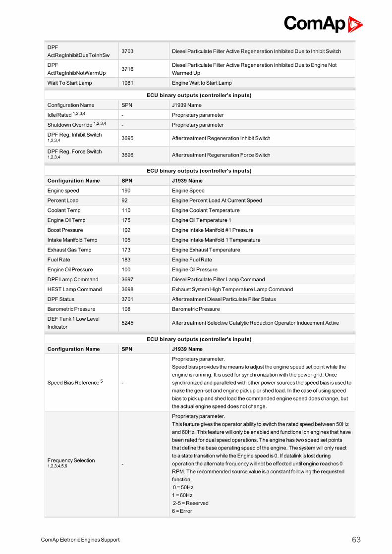
ComApEletronicEnginesSupport 63
DPFActRegInhibitDueToInhSw
3703 DieselParticulate Filter Active Regeneration Inhibited Due to Inhibit Switch
DPFActRegInhibNotWarmUp
3716DieselParticulate Filter Active Regeneration Inhibited Due to Engine NotWarmedUp
Wait To Start Lamp 1081 EngineWait to Start Lamp
ECU binary outputs (controller's inputs)
Configuration Name SPN J1939 Name
Idle/Rated 1,2,3,4 - Proprietary parameter
ShutdownOverride 1,2,3,4 - Proprietary parameter
DPF Reg. Inhibit Switch1,2,3,4 3695 Aftertreatment Regeneration Inhibit Switch
DPF Reg. Force Switch1,2,3,4 3696 Aftertreatment Regeneration Force Switch
ECU binary outputs (controller's inputs)
Configuration Name SPN J1939 Name
Engine speed 190 Engine Speed
Percent Load 92 Engine Percent Load At Current Speed
Coolant Temp 110 Engine Coolant Temperature
EngineOil Temp 175 EngineOil Temperature 1
Boost Pressure 102 Engine IntakeManifold #1 Pressure
IntakeManifold Temp 105 Engine IntakeManifold 1 Temperature
Exhaust GasTemp 173 Engine Exhaust Temperature
FuelRate 183 Engine FuelRate
EngineOil Pressure 100 EngineOil Pressure
DPF LampCommand 3697 DieselParticulate Filter LampCommand
HEST LampCommand 3698 Exhaust SystemHigh Temperature LampCommand
DPF Status 3701 Aftertreatment DieselParticulate Filter Status
BarometricPressure 108 BarometricPressure
DEF Tank1 Low LevelIndicator
5245 Aftertreatment Selective CatalyticReduction Operator Inducement Active
ECU binary outputs (controller's inputs)
Configuration Name SPN J1939 Name
Speed BiasReference 5 -
Proprietary parameter.Speed biasprovides themeans to adjust the engine speed set point while theengine is running. It is used for synchronization with the power grid. Oncesynchronized and paralleled with other power sources the speed bias is used tomake the gen-set and engine pick up or shed load. In the case of using speedbias to pick up and shed load the commanded engine speed does change, butthe actual engine speed doesnot change.
FrequencySelection1,2,3,4,5,6 -
Proprietary parameter.This feature gives the operator ability to switch the rated speed between 50Hzand 60Hz. This feature will only be enabled and functional on engines that havebeen rated for dual speed operations. The engine has two speed set pointsthat define the base operating speed of the engine. The systemwill only reactto a state transition while the Engine speed is 0. If datalink is lost duringoperation the alternate frequencywill not be effected until engine reaches0RPM. The recommended source value is a constant following the requestedfunction.0 = 50Hz1 =60Hz2-5 =Reserved6 =Error
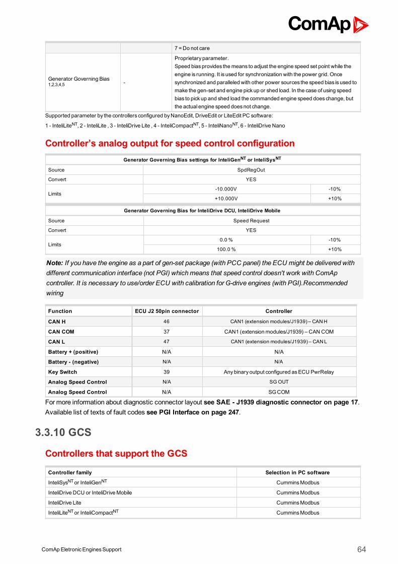
ComApEletronicEnginesSupport 64
7 =Do not care
Generator Governing Bias1,2,3,4,5 -
Proprietary parameter.Speed biasprovides themeans to adjust the engine speed set point while theengine is running. It is used for synchronization with the power grid. Oncesynchronized and paralleled with other power sources the speed bias is used tomake the gen-set and engine pick up or shed load. In the case of using speedbias to pick up and shed load the commanded engine speed does change, butthe actual engine speed doesnot change.
Supported parameter by the controllers configured byNanoEdit, DriveEdit or LiteEdit PC software:
1 - InteliLiteNT, 2 - InteliLite , 3 - InteliDrive Lite , 4 - InteliCompactNT, 5 - InteliNanoNT, 6 - InteliDrive Nano
Controller’s analog output for speed control configurationGenerator Governing Bias settings for InteliGenNT or InteliSysNT
Source SpdRegOut
Convert YES
Limits-10.000V -10%
+10.000V +10%
Generator Governing Bias for InteliDrive DCU, InteliDrive Mobile
Source Speed Request
Convert YES
Limits0.0 % -10%
100.0 % +10%
Note: If you have the engine as a part of gen-set package (with PCC panel) the ECU might be delivered withdifferent communication interface (not PGI) whichmeans that speed control doesn't work with ComApcontroller. It is necessary to use/order ECU with calibration for G-drive engines (with PGI).Recommendedwiring
Function ECU J2 50pin connector Controller
CAN H 46 CAN1 (extension modules/J1939) – CANH
CAN COM 37 CAN1 (extensionmodules/J1939) – CAN COM
CAN L 47 CAN1 (extension modules/J1939) – CANL
Battery + (positive) N/A N/A
Battery - (negative) N/A N/A
Key Switch 39 Anybinary output configured asECU PwrRelay
Analog Speed Control N/A SG OUT
Analog Speed Control N/A SGCOM
Formore information about diagnostic connector layout see SAE - J1939 diagnostic connector on page 17.Available list of texts of fault codes see PGI Interface on page 247.
3.3.10 GCS
Controllers that support the GCS
Controller family Selection in PC software
InteliSysNTor InteliGenNT CumminsModbus
InteliDrive DCU or InteliDriveMobile CumminsModbus
InteliDrive Lite CumminsModbus
InteliLiteNTor InteliCompactNT CumminsModbus
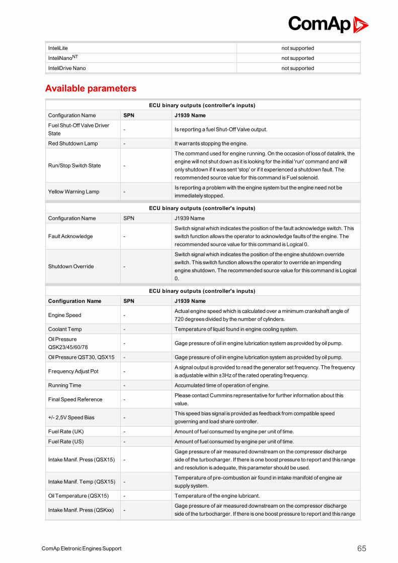
ComApEletronicEnginesSupport 65
InteliLite not supported
InteliNanoNT not supported
InteliDrive Nano not supported
Available parametersECU binary outputs (controller's inputs)
Configuration Name SPN J1939 Name
FuelShut-Off Valve DriverState
- Is reporting a fuelShut-Off Valve output.
Red Shutdown Lamp - It warrants stopping the engine.
Run/Stop Switch State -
The command used for engine running. On the occasion of lossof datalink, theengine will not shut down as it is looking for the initial 'run' command and willonly shutdown if it was sent 'stop' or if it experienced a shutdown fault. Therecommended source value for this command isFuel solenoid.
YellowWarning Lamp -Is reporting a problemwith the engine system but the engine need not beimmediately stopped.
ECU binary outputs (controller's inputs)
Configuration Name SPN J1939 Name
Fault Acknowledge -Switch signalwhich indicates the position of the fault acknowledge switch. Thisswitch function allows the operator to acknowledge faults of the engine. Therecommended source value for this command is Logical 0.
ShutdownOverride -
Switch signalwhich indicates the position of the engine shutdown overrideswitch. This switch function allows the operator to override an impendingengine shutdown. The recommended source value for this command is Logical0.
ECU binary outputs (controller's inputs)
Configuration Name SPN J1939 Name
Engine Speed -Actual engine speed which is calculated over aminimum crankshaft angle of720 degreesdivided by the number of cylinders.
Coolant Temp - Temperature of liquid found in engine cooling system.
Oil PressureQSK23/45/60/78
- Gage pressure of oil in engine lubrication system asprovided byoil pump.
Oil Pressure QST30, QSX15 - Gage pressure of oil in engine lubrication system asprovided byoil pump.
FrequencyAdjust Pot -A signal output is provided to read the generator set frequency. The frequencyis adjustable within ±3Hzof the rated operating frequency.
Running Time - Accumulated time of operation of engine.
FinalSpeed Reference -Please contact Cummins representative for further information about thisvalue.
+/- 2,5VSpeed Bias -This speed bias signal is provided as feedback from compatible speedgoverning and load share controller.
FuelRate (UK) - Amount of fuel consumed byengine per unit of time.
FuelRate (US) - Amount of fuel consumed byengine per unit of time.
IntakeManif. Press (QSX15) -Gage pressure of air measured downstream on the compressor dischargeside of the turbocharger. If there is one boost pressure to report and this rangeand resolution is adequate, this parameter should be used.
IntakeManif. Temp (QSX15) -Temperature of pre-combustion air found in intakemanifold of engine airsupply system.
Oil Temperature (QSX15) - Temperature of the engine lubricant.
IntakeManif. Press (QSKxx) -Gage pressure of air measured downstream on the compressor dischargeside of the turbocharger. If there is one boost pressure to report and this range
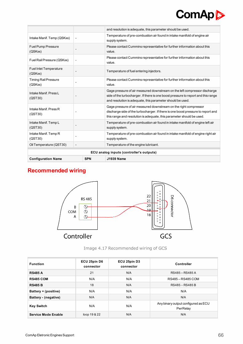
ComApEletronicEnginesSupport 66
and resolution is adequate, this parameter should be used.
IntakeManif. Temp (QSKxx) -Temperature of pre-combustion air found in intakemanifold of engine airsupply system.
FuelPumpPressure(QSKxx)
-Please contact Cummins representative for further information about thisvalue.
FuelRail Pressure (QSKxx) -Please contact Cummins representative for further information about thisvalue.
Fuel Inlet Temperature(QSKxx)
- Temperature of fuel entering injectors.
Timing Rail Pressure(QSKxx)
-Please contact Cummins representative for further information about thisvalue.
IntakeManif. PressL(QST30)
-Gage pressure of air measured downstream on the left compressor dischargeside of the turbocharger. If there is one boost pressure to report and this rangeand resolution is adequate, this parameter should be used.
IntakeManif. PressR(QST30)
-Gage pressure of air measured downstream on the right compressordischarge side of the turbocharger. If there is one boost pressure to report andthis range and resolution is adequate, this parameter should be used.
IntakeManif. Temp L(QST30)
-Temperature of pre-combustion air found in intakemanifold of engine left airsupply system.
IntakeManif. TempR(QST30)
-Temperature of pre-combustion air found in intakemanifold of engine right airsupply system.
Oil Temperature (QST30) - Temperature of the engine lubricant.
ECU analog inputs (controller's outputs)
Configuration Name SPN J1939 Name
Recommended wiring
Image 4.17 Recommended wiring of GCS
FunctionECU 25pin D6connector
ECU 25pin D3connector
Controller
RS485 A 21 N/A RS485 – RS485 A
RS485 COM N/A N/A RS485 – RS485COM
RS485 B 18 N/A RS485 – RS485 B
Battery + (positive) N/A N/A N/A
Battery - (negative) N/A N/A N/A
Key Switch N/A N/AAnybinary output configured asECU
PwrRelay
Service Mode Enable loop 19 & 22 N/A N/A
ComApEletronicEnginesSupport 67
Analog Speed Control N/A 11SGOUT
Analog Speed Control range 2.5VDC –7.5VDC
Analog Speed Control N/A 12 SG COM
Analog Speed ControlShield
N/A 20 N/A
Note: In case that the GCS doesn't communicate try to activate input Diagnostic mode (pin 07 on connectorD6).
Recommended controller settingController Setpoint Value Interface
InteliGenNT
RS232(1) modeRS232(2) mode
ECU LINK
RS485(X)conv.ENABLEDDISABLED
RS485(1), RS 485(2)RS 232(1)1, RS 232(2) 2
InteliSysNTRS232(2) mode ECU LINK
RS485(X)conv.ENABLEDDISABLED
RS485(2)RS 232(1)3, RS 232(2)4
InteliLiteNT COM2Mode ECU LINK RS4855
InteliCompactNT COM2Mode ECU LINK RS4856
InteliDrive DCU RS485Mode ECU LINK RS4857
InteliDrive Mobile RS485Mode ECU LINKRS485
(pin 85(A),pin 87(B),pin 86(COM))
InteliDrive Lite COM2Mode ECU LINK RS4858
Formore information about diagnostic connector layout see SAE - J1939 diagnostic connector on page 17.Available list of texts of fault codes see GCS on page 249.
1external RS232-485 converter is required2external RS232-485 converter is required3external RS232-485 converter is required4external RS232-485 converter is required5IL-NT RS232-485 communicationmodule is required6IL-NT RS232-485 communicationmodule is required7IL-NT RS232-485 communicationmodule is required8IL-NT RS232-485 communicationmodule is required
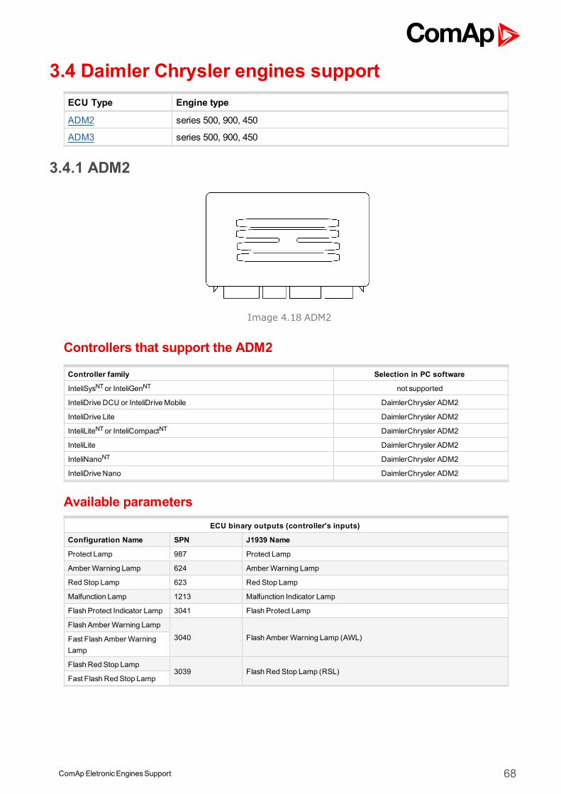
ComApEletronicEnginesSupport 68
3.4 Daimler Chrysler engines supportECU Type Engine type
ADM2 series 500, 900, 450
ADM3 series 500, 900, 450
3.4.1 ADM2
Image 4.18 ADM2
Controllers that support the ADM2
Controller family Selection in PC software
InteliSysNTor InteliGenNT not supported
InteliDrive DCU or InteliDriveMobile DaimlerChrysler ADM2
InteliDrive Lite DaimlerChrysler ADM2
InteliLiteNTor InteliCompactNT DaimlerChrysler ADM2
InteliLite DaimlerChrysler ADM2
InteliNanoNT DaimlerChrysler ADM2
InteliDrive Nano DaimlerChrysler ADM2
Available parametersECU binary outputs (controller's inputs)
Configuration Name SPN J1939 Name
Protect Lamp 987 Protect Lamp
Amber Warning Lamp 624 Amber Warning Lamp
Red Stop Lamp 623 Red Stop Lamp
Malfunction Lamp 1213 Malfunction Indicator Lamp
Flash Protect Indicator Lamp 3041 Flash Protect Lamp
Flash Amber Warning Lamp
3040 Flash Amber Warning Lamp (AWL)Fast Flash Amber WarningLamp
Flash Red Stop Lamp3039 Flash Red Stop Lamp (RSL)
Fast Flash Red Stop Lamp
ComApEletronicEnginesSupport 69
ECU binary outputs (controller's inputs)
Configuration Name SPN J1939 Name
Inhibit fuel injection 1,2,3,4,5,6 -Proprietary parameter.The command used for engine fuel injection inhibits. The recommendedsource value for this command is Logical 0.
Engine start 1,2,3,4,5,6 -Proprietary parameter.The command used for engine start. The recommended source value for thiscommand isFuel solenoid.
Inhibit engine start -Proprietary parameter.The command used for engine start inhibits. The recommended source valuefor this command is Logical 0.
TorqueConvLockupEngaged- Proprietary parameter
Engine overspeed enable - Proprietary parameter
ECU binary outputs (controller's inputs)
Configuration Name SPN J1939 Name
Engine speed 190 Engine Speed
Actual Torque 513 ActualEngine - Percent Torque
Demand Torque 512 Driver'sDemand Engine - Percent Torque
Coolant Temp 110 Engine Coolant Temperature
EngineOil Temp 175 EngineOil Temperature 1
Boost Pressure 102 Engine IntakeManifold #1 Pressure
IntakeManifold Temp 105 Engine IntakeManifold 1 Temperature
Accelerator PedalPosition 91 Accelerator PedalPosition 1
Percent Load 92 Engine Percent Load At Current Speed
FuelRate 183 Engine FuelRate
EngineOil Level 98 EngineOil Level
EngineOil Pressure 100 EngineOil Pressure
ECU binary outputs (controller's inputs)
Configuration Name SPN J1939 Name
Requested speed 1,2,3,4,5,6 898 Engine Requested Speed/Speed Limit
Output shaft speed 191 TransmissionOutput Shaft Speed
Supported parameter by the controllers configured byNanoEdit, DriveEdit or LiteEdit PC software:
1 - InteliLiteNT, 2 - InteliLite , 3 - InteliDrive Lite , 4 - InteliCompactNT, 5 - InteliNanoNT, 6 - InteliDrive Nano
Controller’s analog output for speed control configurationRequested speed settings for InteliGenNT or InteliSysNT
Source SpeedReq RPM
Convert NO
LimitsN/A N/A
N/A N/A
Requested speed settings for InteliDrive DCU, InteliDrive Mobile
Source SpeedReq RPM
Convert NO
Limits0.0 % Min eng. speed (800RPM)
100.0 % Max eng. speed (2100RPM)
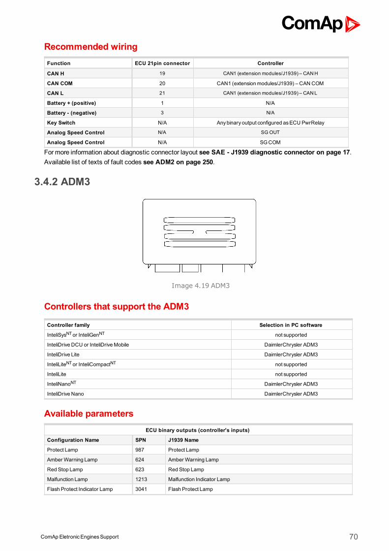
ComApEletronicEnginesSupport 70
Recommended wiringFunction ECU 21pin connector Controller
CAN H 19 CAN1 (extension modules/J1939) – CANH
CAN COM 20 CAN1 (extensionmodules/J1939) – CAN COM
CAN L 21 CAN1 (extension modules/J1939) – CANL
Battery + (positive) 1 N/A
Battery - (negative) 3 N/A
Key Switch N/A Anybinary output configured asECU PwrRelay
Analog Speed Control N/A SG OUT
Analog Speed Control N/A SGCOM
Formore information about diagnostic connector layout see SAE - J1939 diagnostic connector on page 17.Available list of texts of fault codes see ADM2 on page 250.
3.4.2 ADM3
Image 4.19 ADM3
Controllers that support the ADM3
Controller family Selection in PC software
InteliSysNTor InteliGenNT not supported
InteliDrive DCU or InteliDriveMobile DaimlerChrysler ADM3
InteliDrive Lite DaimlerChrysler ADM3
InteliLiteNTor InteliCompactNT not supported
InteliLite not supported
InteliNanoNT DaimlerChrysler ADM3
InteliDrive Nano DaimlerChrysler ADM3
Available parametersECU binary outputs (controller's inputs)
Configuration Name SPN J1939 Name
Protect Lamp 987 Protect Lamp
Amber Warning Lamp 624 Amber Warning Lamp
Red Stop Lamp 623 Red Stop Lamp
Malfunction Lamp 1213 Malfunction Indicator Lamp
Flash Protect Indicator Lamp 3041 Flash Protect Lamp
ComApEletronicEnginesSupport 71
Flash Amber Warning Lamp3040 Flash Amber Warning Lamp (AWL)
Fast Flash Amber Warning Lamp
Flash Red Stop Lamp3039 Flash Red Stop Lamp (RSL)
Fast Flash Red Stop Lamp
ECU binary inputs (controller's outputs - commands)
Configuration Name SPN J1939 Name
Inhibit fuel injection 1,2,3,4,5,6 -Proprietary parameter.The command used for engine fuel injection inhibits. The recommended source valuefor this command is Logical 0.
Engine start 1,2,3,4,5,6 -Proprietary parameter.The command used for engine start. The recommended source value for thiscommand isFuel solenoid.
Inhibit engine start -Proprietary parameter.The command used for engine start inhibits. The recommended source value for thiscommand is Logical 0.
TorqueConvLockupEngaged - Proprietary parameter
Engine overspeed enable - Proprietary parameter
ECU analog outputs (controller's inputs)
Configuration Name SPN J1939 Name
Engine speed 190 Engine Speed
Actual Torque 513 ActualEngine - Percent Torque
Demand Torque 512 Driver'sDemand Engine - Percent Torque
Coolant Temp 110 Engine Coolant Temperature
EngineOil Temp 175 EngineOil Temperature 1
Boost Pressure 102 Engine IntakeManifold #1 Pressure
IntakeManifold Temp 105 Engine IntakeManifold 1 Temperature
Accelerator PedalPosition 91 Accelerator PedalPosition 1
Percent Load 92 Engine Percent Load At Current Speed
FuelRate 183 Engine FuelRate
EngineOil Level 98 EngineOil Level
EngineOil Pressure 100 EngineOil Pressure
ECU analog inputs (controller's outputs)
Configuration Name SPN J1939 Name
Requested speed 1,2,3,4,5,6 898 Engine Requested Speed/Speed Limit
Output shaft speed 191 TransmissionOutput Shaft Speed
Supported parameter by the controllers configured byNanoEdit, DriveEdit or LiteEdit PC software:
1 - InteliLiteNT, 2 - InteliLite , 3 - InteliDrive Lite , 4 - InteliCompactNT, 5 - InteliNanoNT, 6 - InteliDrive Nano
Controller’s analog output for speed control configurationRequested speed settings for InteliGenNT or InteliSysNT
Source SpeedReq RPM
Convert NO
LimitsN/A N/A
N/A N/A
Requested speed settings for InteliDrive DCU, InteliDrive Mobile
Source SpeedReq RPM
Convert NO
ComApEletronicEnginesSupport 72
Limits0.0 % Min eng. speed (800RPM)
100.0 % Max eng. speed (2100RPM)
Controller’s analog output for speed control configurationRequested speed settings for InteliGenNT or InteliSysNT
Source SpeedReq RPM
Convert NO
LimitsN/A N/A
N/A N/A
Requested speed settings for InteliDrive DCU, InteliDrive Mobile
Source SpeedReq RPM
Convert NO
Limits0.0 % Min eng. speed (800RPM)
100.0 % Max eng. speed (2100RPM)
Recommended wiringFunction ECU 21pin connector Controller
CAN H 19 CAN1 (extension modules/J1939) – CANH
CAN COM 20 CAN1 (extensionmodules/J1939) – CAN COM
CAN L 21 CAN1 (extension modules/J1939) – CANL
Battery + (positive) 1 N/A
Battery - (negative) 3 N/A
Key Switch N/A Anybinary output configured asECU PwrRelay
Analog Speed Control N/A SG OUT
Analog Speed Control N/A SGCOM
Formore information about diagnostic connector layout see SAE - J1939 diagnostic connector on page 17.Available list of texts of fault codes see ADM3 on page 252.
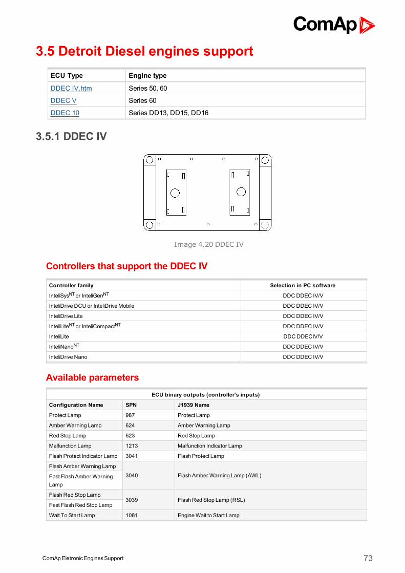
ComApEletronicEnginesSupport 73
3.5 Detroit Diesel engines supportECU Type Engine type
DDEC IV.htm Series 50, 60
DDEC V Series 60
DDEC 10 Series DD13, DD15, DD16
3.5.1 DDEC IV
Image 4.20 DDEC IV
Controllers that support the DDEC IV
Controller family Selection in PC software
InteliSysNTor InteliGenNT DDCDDEC IV/V
InteliDrive DCU or InteliDriveMobile DDC DDEC IV/V
InteliDrive Lite DDC DDEC IV/V
InteliLiteNTor InteliCompactNT DDCDDEC IV/V
InteliLite DDC DDECIV/V
InteliNanoNT DDCDDEC IV/V
InteliDrive Nano DDC DDEC IV/V
Available parametersECU binary outputs (controller's inputs)
Configuration Name SPN J1939 Name
Protect Lamp 987 Protect Lamp
Amber Warning Lamp 624 Amber Warning Lamp
Red Stop Lamp 623 Red Stop Lamp
Malfunction Lamp 1213 Malfunction Indicator Lamp
Flash Protect Indicator Lamp 3041 Flash Protect Lamp
Flash Amber Warning Lamp
3040 Flash Amber Warning Lamp (AWL)Fast Flash Amber WarningLamp
Flash Red Stop Lamp3039 Flash Red Stop Lamp (RSL)
Fast Flash Red Stop Lamp
Wait To Start Lamp 1081 EngineWait to Start Lamp
ComApEletronicEnginesSupport 74
ECU binary inputs (controller's outputs - commands)
Configuration Name SPN J1939 Name
ECU binary outputs (controller's inputs)
Configuration Name SPN J1939 Name
Engine speed 190 Engine Speed
Actual Torque 513 ActualEngine - Percent Torque
Demand Torque 512 Driver'sDemand Engine - Percent Torque
Coolant Temp 110 Engine Coolant Temperature
EngineOil Temp 175 EngineOil Temperature 1
Boost Pressure 102 Engine IntakeManifold #1 Pressure
IntakeManifold Temp 105 Engine IntakeManifold 1 Temperature
Air Intake Pressure 106 Engine Intake Air Pressure
Exhaust GasTemp 173 Engine Exhaust Temperature
Accelerator PedalPosition 91 Accelerator PedalPosition 1
Percent Load 92 Engine Percent Load At Current Speed
FuelRate 183 Engine FuelRate
BatteryPotential (Voltage) 158 Keyswitch BatteryPotential
FuelDeliveryPressure 94 Engine FuelDeliveryPressure
EngineOil Level 98 EngineOil Level
EngineOil Pressure 100 EngineOil Pressure
Crankcase Pressure 101 Engine Crankcase Pressure 1
Coolant Pressure 109 Engine Coolant Pressure 1
Coolant Level 111 Engine Coolant Level 1
ECU binary outputs (controller's inputs)
Configuration Name SPN J1939 Name
Requested speed 1,2,3,4,5,6 898 Engine Requested Speed/Speed Limit
Supported parameter by the controllers configured byNanoEdit, DriveEdit or LiteEdit PC software:
1 - InteliLiteNT, 2 - InteliLite , 3 - InteliDrive Lite , 4 - InteliCompactNT, 5 - InteliNanoNT, 6 - InteliDrive Nano
Controller’s analog output for speed control configurationRequested speed settings for InteliGenNT or InteliSysNT
Source SpeedReq RPM
Convert NO
LimitsN/A N/A
N/A N/A
Requested speed settings for InteliDrive DCU, InteliDrive Mobile
Source SpeedReq RPM
Convert NO
Limits0.0 % Min eng. speed (800RPM)
100.0 % Max eng. speed (2100RPM)
Recommended wiring
Function6pin communication
connectorController
CAN H F CAN1 (extension modules/J1939) – CANH
CAN COM D CAN1 (extensionmodules/J1939) – CAN COM
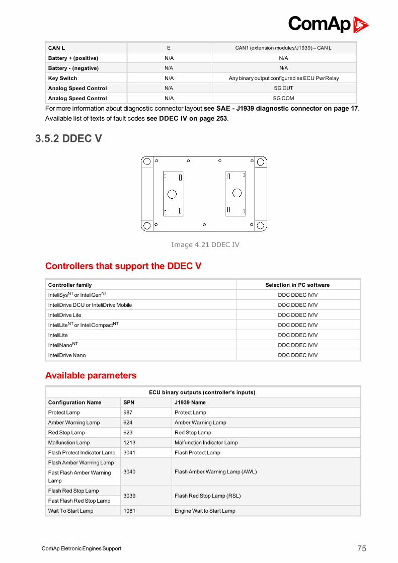
ComApEletronicEnginesSupport 75
CAN L E CAN1 (extension modules/J1939) – CANL
Battery + (positive) N/A N/A
Battery - (negative) N/A N/A
Key Switch N/A Anybinary output configured asECU PwrRelay
Analog Speed Control N/A SG OUT
Analog Speed Control N/A SGCOM
Formore information about diagnostic connector layout see SAE - J1939 diagnostic connector on page 17.Available list of texts of fault codes see DDEC IV on page 253.
3.5.2 DDEC V
Image 4.21 DDEC IV
Controllers that support the DDEC V
Controller family Selection in PC software
InteliSysNTor InteliGenNT DDCDDEC IV/V
InteliDrive DCU or InteliDriveMobile DDC DDEC IV/V
InteliDrive Lite DDC DDEC IV/V
InteliLiteNTor InteliCompactNT DDCDDEC IV/V
InteliLite DDC DDEC IV/V
InteliNanoNT DDCDDEC IV/V
InteliDrive Nano DDC DDEC IV/V
Available parametersECU binary outputs (controller's inputs)
Configuration Name SPN J1939 Name
Protect Lamp 987 Protect Lamp
Amber Warning Lamp 624 Amber Warning Lamp
Red Stop Lamp 623 Red Stop Lamp
Malfunction Lamp 1213 Malfunction Indicator Lamp
Flash Protect Indicator Lamp 3041 Flash Protect Lamp
Flash Amber Warning Lamp
3040 Flash Amber Warning Lamp (AWL)Fast Flash Amber WarningLamp
Flash Red Stop Lamp3039 Flash Red Stop Lamp (RSL)
Fast Flash Red Stop Lamp
Wait To Start Lamp 1081 EngineWait to Start Lamp

ComApEletronicEnginesSupport 76
ECU binary outputs (controller's inputs)
Configuration Name SPN J1939 Name
ECU binary outputs (controller's inputs)
Configuration Name SPN J1939 Name
Engine speed 190 Engine Speed
Actual Torque 513 ActualEngine - Percent Torque
Demand Torque 512 Driver'sDemand Engine - Percent Torque
Coolant Temp 110 Engine Coolant Temperature
EngineOil Temp 175 EngineOil Temperature 1
Boost Pressure 102 Engine IntakeManifold #1 Pressure
IntakeManifold Temp 105 Engine IntakeManifold 1 Temperature
Air Intake Pressure 106 Engine Intake Air Pressure
Exhaust GasTemp 173 Engine Exhaust Temperature
Accelerator PedalPosition 91 Accelerator PedalPosition 1
Percent Load 92 Engine Percent Load At Current Speed
FuelRate 183 Engine FuelRate
BatteryPotential (Voltage) 158 Keyswitch BatteryPotential
FuelDeliveryPressure 94 Engine FuelDeliveryPressure
EngineOil Level 98 EngineOil Level
EngineOil Pressure 100 EngineOil Pressure
Crankcase Pressure 101 Engine Crankcase Pressure 1
Coolant Pressure 109 Engine Coolant Pressure 1
Coolant Level 111 Engine Coolant Level 1
ECU binary outputs (controller's inputs)
Configuration Name SPN J1939 Name
Requested speed 1,2,3,4,5,6 898 Engine Requested Speed/Speed Limit
Supported parameter by the controllers configured byNanoEdit, DriveEdit or LiteEdit PC software:
1 - InteliLiteNT, 2 - InteliLite , 3 - InteliDrive Lite , 4 - InteliCompactNT, 5 - InteliNanoNT, 6 - InteliDrive Nano
Controller’s analog output for speed control configurationRequested speed settings for InteliGenNT or InteliSysNT
Source SpeedReq RPM
Convert NO
LimitsN/A N/A
N/A N/A
Requested speed settings for InteliDrive DCU, InteliDrive Mobile
Source SpeedReq RPM
Convert NO
Limits0.0 % Min eng. speed (800RPM)
100.0 % Max eng. speed (2100RPM)
Recommended wiring
Function6pin communication
connectorController
CAN H F CAN1 (extension modules/J1939) – CANH
CAN COM D CAN1 (extensionmodules/J1939) – CAN COM
ComApEletronicEnginesSupport 77
CAN L E CAN1 (extension modules/J1939) – CANL
Battery + (positive) N/A N/A
Battery - (negative) N/A N/A
Key Switch N/A Anybinary output configured asECU PwrRelay
Analog Speed Control N/A SG OUT
Analog Speed Control N/A SGCOM
Formore information about diagnostic connector layout see SAE - J1939 diagnostic connector on page 17.Available list of texts of fault codes see DDEC V on page 254.
ComApEletronicEnginesSupport 78
3.6 Deutz engines supportECU Type Engine type
EMR2 10xx series
EMR3-E (EDC16, EDC7)TCD 2012 4VTCD 2013 4VTCD 2015
EMR3-S (EDC16, EDC7)TCD 2012 2VTCD 2013 2VTCD 2013 4V
EMR4 (EDC17CV52)
TCD 3.6 L4TCD 4.1 L4TCD 6.1 L6TCD 7.8 L6TCD 12 V6TCD 16 V8
TEM EvolutionTBG 616/620/632TCG 2016/2020/2032
Previous engine designation New engine designation
TCD 20xxL04TCD 2010 L04TCD 2012 L04TCD 2012 L06TCD 2013 L06TCD 2015 V06TCD 2015 V08
TCD 2.9 L4TCD 3.6 L4TCD 4.1 L4TCD 6.1 L6TCD 7.8 L6TCD 12 V6TCD 16 V8
3.6.1 Engine type explanationEngine Code Meaning
Txxxxxx Turbocharged
xCxxxxx Charge air cooled
xxDxxxx Diesel engine
xxx12xx Displacement in liters
xxxxxLxL – in line engine,V – V-engine
xxxxxx6 Number of cylinders
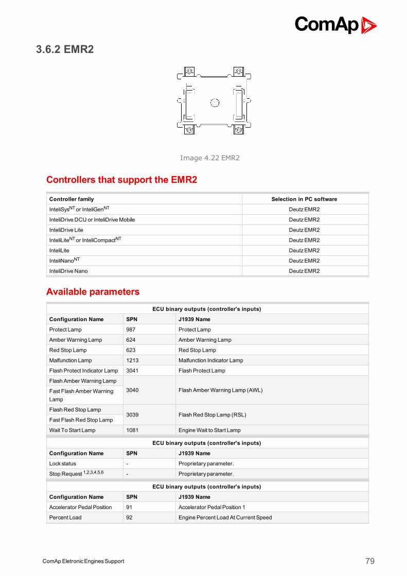
ComApEletronicEnginesSupport 79
3.6.2 EMR2
Image 4.22 EMR2
Controllers that support the EMR2
Controller family Selection in PC software
InteliSysNTor InteliGenNT DeutzEMR2
InteliDrive DCU or InteliDriveMobile DeutzEMR2
InteliDrive Lite DeutzEMR2
InteliLiteNTor InteliCompactNT DeutzEMR2
InteliLite DeutzEMR2
InteliNanoNT DeutzEMR2
InteliDrive Nano DeutzEMR2
Available parametersECU binary outputs (controller's inputs)
Configuration Name SPN J1939 Name
Protect Lamp 987 Protect Lamp
Amber Warning Lamp 624 Amber Warning Lamp
Red Stop Lamp 623 Red Stop Lamp
Malfunction Lamp 1213 Malfunction Indicator Lamp
Flash Protect Indicator Lamp 3041 Flash Protect Lamp
Flash Amber Warning Lamp
3040 Flash Amber Warning Lamp (AWL)Fast Flash Amber WarningLamp
Flash Red Stop Lamp3039 Flash Red Stop Lamp (RSL)
Fast Flash Red Stop Lamp
Wait To Start Lamp 1081 EngineWait to Start Lamp
ECU binary outputs (controller's inputs)
Configuration Name SPN J1939 Name
Lock status - Proprietary parameter.
Stop Request 1,2,3,4,5,6 - Proprietary parameter.
ECU binary outputs (controller's inputs)
Configuration Name SPN J1939 Name
Accelerator PedalPosition 91 Accelerator PedalPosition 1
Percent Load 92 Engine Percent Load At Current Speed
ComApEletronicEnginesSupport 80
Demand Torque 512 Driver'sDemand Engine - Percent Torque
Actual Torque 513 ActualEngine - Percent Torque
Engine speed 190 Engine Speed
Coolant Temp 110 Engine Coolant Temperature
Fuel Temp 174 Engine Fuel Temperature 1
EngineOil Temp 175 EngineOil Temperature 1
EngineOil Level 98 EngineOil Level
EngineOil Pressure 100 EngineOil Pressure
Coolant Level 111 Engine Coolant Level 1
FuelRate 183 Engine FuelRate
Boost Pressure 102 Engine IntakeManifold #1 Pressure
IntakeManifold Temp 105 Engine IntakeManifold 1 Temperature
BatteryPotential (Voltage) 158 Keyswitch BatteryPotential
ECU binary outputs (controller's inputs)
Configuration Name SPN J1939 Name
Requested speed 1,2,3,4,5,6 898 Engine Requested Speed/Speed Limit
Supported parameter by the controllers configured byNanoEdit, DriveEdit or LiteEdit PC software:
1 - InteliLiteNT, 2 - InteliLite , 3 - InteliDrive Lite , 4 - InteliCompactNT, 5 - InteliNanoNT, 6 - InteliDrive Nano
Controller’s analog output for speed control configurationRequested speed settings for InteliGenNT or InteliSysNT
Source SpeedReq RPM
Convert NO
LimitsN/A N/A
N/A N/A
Requested speed settings for InteliDrive DCU, InteliDrive Mobile
Source SpeedReq RPM
Convert NO
Limits0.0 % Min eng. speed (800RPM)
100.0 % Max eng. speed (2100RPM)
IMPORTANT: Deutz does not recommend switching off the engine by removing the power supply(battery). It causes fault code SPN=536.
Recommended setting of EMR2 using Serdia PC toolNote:Page 30: 4400 = 1…CAN activationPage 31: 4412 = 1…Activate TSC1a receive telegramPage 31: 4470 = 1…Activate CAN set point by TSC1aPage 12: 4829 = 8…Enable stop request telegramPage 10: 4900 = 8…Selection of input channel type for nominal speed value sensor829 = FunctEngineStop – Switch assignment for “Engine stop” function4424 = TelStopRequestOn – SAEJ1939: Active Engine Stop Request receives telegram
ComApEletronicEnginesSupport 81
Recommended wiringFunction ECU 25pin F connector Controller
CAN H 12 CAN1 (extension modules/J1939) – CANH
CAN COM N/A CAN1 (extensionmodules/J1939) – CAN COM
CAN L 13 CAN1 (extension modules/J1939) – CANL
Battery + (positive) 14 N/A
Battery - (negative) 1 N/A
Key Switch N/A Anybinary output configured asECU PwrRelay
Analog Speed Control N/A SG OUT
Analog Speed Control N/A SGCOM
Formore information about diagnostic connector layout see SAE - J1939 diagnostic connector on page 17.Available list of texts of fault codes see EMR2 on page 255.
3.6.3 EMR3-E
Image 4.23 EMR3-E
Controllers that support the EMR3-E
Controller family Selection in PC software
InteliSysNTor InteliGenNT DeutzEMR3
InteliDrive DCU or InteliDriveMobile DeutzEMR3
InteliDrive Lite DeutzEMR3
InteliLiteNTor InteliCompactNT DeutzEMR3
InteliLite DeutzEMR3
InteliNanoNT DeutzEMR3
InteliDrive Nano DeutzEMR3
Available parametersECU binary outputs (controller's inputs)
Configuration Name SPN J1939 Name
Protect Lamp 987 Protect Lamp
Amber Warning Lamp 624 Amber Warning Lamp
Red Stop Lamp 623 Red Stop Lamp
Malfunction Lamp 1213 Malfunction Indicator Lamp
Flash Protect Indicator Lamp 3041 Flash Protect Lamp
ComApEletronicEnginesSupport 82
Flash Amber Warning Lamp
3040 Flash Amber Warning Lamp (AWL)Fast Flash Amber WarningLamp
Flash Red Stop Lamp3039 Flash Red Stop Lamp (RSL)
Fast Flash Red Stop Lamp
Wait To Start Lamp 1081 EngineWait to Start Lamp
ECU binary outputs (controller's inputs)
Configuration Name SPN J1939 Name
Lock status - Proprietary parameter.
Stop Request 1,2,3,4,5,6 - Proprietary parameter.
Start Lock 4 - Proprietary parameter.
ECU binary outputs (controller's inputs)
Configuration Name SPN J1939 Name
Accelerator PedalPosition 91 Accelerator PedalPosition 1
Percent Load 92 Engine Percent Load At Current Speed
Demand Torque 512 Driver'sDemand Engine - Percent Torque
Actual Torque 513 ActualEngine - Percent Torque
Engine speed 190 Engine Speed
Coolant Temp 110 Engine Coolant Temperature
Fuel Temp 174 Engine Fuel Temperature 1
EngineOil Temp 175 EngineOil Temperature 1
Fuel delivery pressure 94 Engine FuelDeliveryPressure
EngineOil Pressure 100 EngineOil Pressure
Coolant Level 111 Engine Coolant Level 1
FuelRate 183 Engine FuelRate
Boost Pressure 102 Engine IntakeManifold #1 Pressure
IntakeManifold Temp 105 Engine IntakeManifold 1 Temperature
BatteryPotential (Voltage) 158 Keyswitch BatteryPotential
ECU binary outputs (controller's inputs)
Configuration Name SPN J1939 Name
Requested speed 1,2,3,4,5,6 898 Engine Requested Speed/Speed Limit
TorqueMap -
Proprietary parameter.0 = nomodification of torquemap1 = switch to torquemap 12 = switch to torquemap 2
Engine speed droop -
Proprietary parameter.0 = nomodification of droop1 = selects droop 12 = selects droop 2
High Idle Droop -
Proprietary parameter.0 = nomodification of high idle droop1 = selects high idle droop 12 = selects high idle droop 2
Supported parameter by the controllers configured byNanoEdit, DriveEdit or LiteEdit PC software:
1 - InteliLiteNT, 2 - InteliLite , 3 - InteliDrive Lite , 4 - InteliCompactNT, 5 - InteliNanoNT, 6 - InteliDrive Nano
ComApEletronicEnginesSupport 83
Controller’s analog output for speed control configurationRequested speed settings for InteliGenNT or InteliSysNT
Source SpeedReq RPM
Convert NO
LimitsN/A N/A
N/A N/A
Requested speed settings for InteliDrive DCU, InteliDrive Mobile
Source SpeedReq RPM
Convert NO
Limits0.0 % Min eng. speed (800RPM)
100.0 % Max eng. speed (2100RPM)
IMPORTANT: It is not allowed by Deutz to control speed over CAN bus on gen-set engines! Usepedal position input on ECU instead. The SG OUT signal MUST NOT exceed the limits otherwiseEMR3 blocks speed control via this input. Therefore it is recommended to keep the controllerpowered on always while the EMR3 is powered on (by Klemme 30). Or it is necessary to switch offthis protection in EMR3.
Note: EMR3-E has internal relay providing power supply to EMR3. As soon as the ignition key is turned off(Klemme 15) themain relay switches off the EMR3within cca. 10 seconds. Themain relay separates theEMR3 from the battery + (Klemme 30).
Recommended wiringFunction ECU D2 connector Controller
CAN H 35 CAN1 (extension modules/J1939) – CANH
CAN COM N/A CAN1 (extensionmodules/J1939) – CAN COM
CAN L 34 CAN1 (extension modules/J1939) – CANL
Battery + (positive) 2,3,8,9 (loop 30) N/A
Battery - (negative) 5,6,10,11 (loop31) N/A
Key Switch 40 Anybinary output configured asECU PwrRelay
Analog Speed Control 79SG OUT
Range 0VDC to 5VDC,100kOhmpull-down resistance
Analog Speed Control 78 SGCOM
Formore information about diagnostic connector layout see SAE - J1939 diagnostic connector on page 17.Available list of texts of fault codes see EMR3-E on page 256.
3.6.4 EMR3-S
Controllers that support the EMR3-S
Controller family Selection in PC software
InteliSysNTor InteliGenNT DeutzEMR3
InteliDrive DCU or InteliDriveMobile DeutzEMR3
InteliDrive Lite DeutzEMR3
InteliLiteNTor InteliCompactNT DeutzEMR3
ComApEletronicEnginesSupport 84
InteliLite DeutzEMR3
InteliNanoNT DeutzEMR3
InteliDrive Nano DeutzEMR3
Available parametersECU binary outputs (controller's inputs)
Configuration Name SPN J1939 Name
Protect Lamp 987 Protect Lamp
Amber Warning Lamp 624 Amber Warning Lamp
Red Stop Lamp 623 Red Stop Lamp
Malfunction Lamp 1213 Malfunction Indicator Lamp
Flash Protect Indicator Lamp 3041 Flash Protect Lamp
Flash Amber Warning Lamp
3040 Flash Amber Warning Lamp (AWL)Fast Flash Amber WarningLamp
Flash Red Stop Lamp3039 Flash Red Stop Lamp (RSL)
Fast Flash Red Stop Lamp
Wait To Start Lamp 1081 EngineWait to Start Lamp
ECU binary outputs (controller's inputs)
Configuration Name SPN J1939 Name
Lock status - Proprietary parameter.
Stop Request 1,2,3,4,5,6 - Proprietary parameter.
Start Lock 4 - Proprietary parameter.
ECU analog outputs (controller's inputs)
Configuration Name SPN J1939 Name
Accelerator PedalPosition 91 Accelerator PedalPosition 1
Percent Load 92 Engine Percent Load At Current Speed
Demand Torque 512 Driver'sDemand Engine - Percent Torque
Actual Torque 513 ActualEngine - Percent Torque
Engine speed 190 Engine Speed
Coolant Temp 110 Engine Coolant Temperature
Fuel Temp 174 Engine Fuel Temperature 1
EngineOil Temp 175 EngineOil Temperature 1
Fuel delivery pressure 94 Engine FuelDeliveryPressure
EngineOil Pressure 100 EngineOil Pressure
Coolant Level 111 Engine Coolant Level 1
FuelRate 183 Engine FuelRate
Boost Pressure 102 Engine IntakeManifold #1 Pressure
IntakeManifold Temp 105 Engine IntakeManifold 1 Temperature
BatteryPotential (Voltage) 158 Keyswitch BatteryPotential
ECU analog inputs (controller's outputs)
Configuration Name SPN J1939 Name
Requested speed 1,2,3,4,5,6 898 Engine Requested Speed/Speed Limit
ComApEletronicEnginesSupport 85
TorqueMap -
Proprietary parameter.0 = nomodification of torquemap1 = switch to torquemap 12 = switch to torquemap 2
Engine speed droop -
Proprietary parameter.0 = nomodification of droop1 = selects droop 12 = selects droop 2
High Idle Droop -
Proprietary parameter.0 = nomodification of high idle droop1 = selects high idle droop 12 = selects high idle droop 2
Supported parameter by the controllers configured byNanoEdit, DriveEdit or LiteEdit PC software:
1 - InteliLiteNT, 2 - InteliLite , 3 - InteliDrive Lite , 4 - InteliCompactNT, 5 - InteliNanoNT, 6 - InteliDrive Nano
Controller’s analog output for speed control configurationRequested speed settings for InteliGenNT or InteliSysNT
Source SpeedReq RPM
Convert NO
LimitsN/A N/A
N/A N/A
Requested speed settings for InteliDrive DCU, InteliDrive Mobile
Source SpeedReq RPM
Convert NO
Limits0.0 % Min eng. speed (800RPM)
100.0 % Max eng. speed (2100RPM)
IMPORTANT: It is not allowed by Deutz to control speed over CAN bus on gen-set engines! Usepedal position input on ECU instead. The SG OUT signal MUST NOT exceed the limits otherwiseEMR3 blocks speed control via this input. Therefore it is recommended to keep the controllerpowered on always while the EMR3 is powered on. Or it is necessary to switch off this protection inEMR3.
Note: EMR3-S has internal relay providing power supply to EMR3. As soon as the ignition key is turned off themain relay switches off the EMR3within cca. 10 seconds. Themain relay separates the EMR3 from the battery+.
Recommended wiringFunction ECU D2 connector Controller
CAN H 62 CAN1 (extension modules/J1939) – CANH
CAN COM N/A CAN1 (extensionmodules/J1939) – CAN COM
CAN L 61 CAN1 (extension modules/J1939) – CANL
Battery + (positive) 1,3,5 N/A
Battery - (negative) 2,4,6 N/A
Key Switch 28 Anybinary output configured asECU PwrRelay
Analog Speed Control 9SG OUT
Range 0VDC to 5VDC,100kOhmpull-down resistance
Analog Speed Control 30 SGCOM
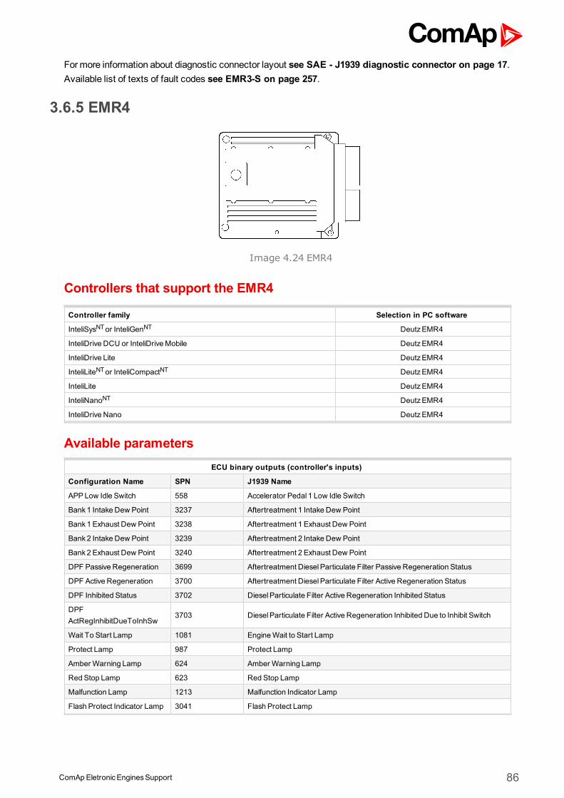
ComApEletronicEnginesSupport 86
Formore information about diagnostic connector layout see SAE - J1939 diagnostic connector on page 17.Available list of texts of fault codes see EMR3-S on page 257.
3.6.5 EMR4
Image 4.24 EMR4
Controllers that support the EMR4
Controller family Selection in PC software
InteliSysNTor InteliGenNT DeutzEMR4
InteliDrive DCU or InteliDriveMobile DeutzEMR4
InteliDrive Lite DeutzEMR4
InteliLiteNTor InteliCompactNT DeutzEMR4
InteliLite DeutzEMR4
InteliNanoNT DeutzEMR4
InteliDrive Nano DeutzEMR4
Available parametersECU binary outputs (controller's inputs)
Configuration Name SPN J1939 Name
APPLow Idle Switch 558 Accelerator Pedal 1 Low Idle Switch
Bank1 Intake Dew Point 3237 Aftertreatment 1 Intake Dew Point
Bank1 Exhaust Dew Point 3238 Aftertreatment 1 Exhaust Dew Point
Bank2 Intake Dew Point 3239 Aftertreatment 2 Intake Dew Point
Bank2 Exhaust Dew Point 3240 Aftertreatment 2 Exhaust Dew Point
DPF Passive Regeneration 3699 Aftertreatment DieselParticulate Filter Passive Regeneration Status
DPF Active Regeneration 3700 Aftertreatment DieselParticulate Filter Active Regeneration Status
DPF Inhibited Status 3702 DieselParticulate Filter Active Regeneration Inhibited Status
DPFActRegInhibitDueToInhSw
3703 DieselParticulate Filter Active Regeneration Inhibited Due to Inhibit Switch
Wait To Start Lamp 1081 EngineWait to Start Lamp
Protect Lamp 987 Protect Lamp
Amber Warning Lamp 624 Amber Warning Lamp
Red Stop Lamp 623 Red Stop Lamp
Malfunction Lamp 1213 Malfunction Indicator Lamp
Flash Protect Indicator Lamp 3041 Flash Protect Lamp
ComApEletronicEnginesSupport 87
Flash Amber Warning Lamp
3040 Flash Amber Warning Lamp (AWL)Fast Flash Amber WarningLamp
Flash Red Stop Lamp3039 Flash Red Stop Lamp (RSL)
Fast Flash Red Stop Lamp
ECU binary outputs (controller's inputs)
Configuration Name SPN J1939 Name
Start LockEP - Proprietary parameter.
Stop Request 1,2,3,4,5,6 - Proprietary parameter.
Start Lock 1,2,3,4,5,6 - Proprietary parameter.
DPF Regeneration Inhibit1,2,3,4 3695 Aftertreatment Regeneration Inhibit Switch
DPF Regeneration Force1,2,3,4 3696 Aftertreatment Regeneration Force Switch
DPF Regeneration Request - Proprietary parameter.
DPF Inhibit Command - Proprietary parameter.
ECU binary outputs (controller's inputs)
Configuration Name SPN J1939 Name
Demand Torque 512 Driver'sDemand Engine - Percent Torque
Actual Torque 513 ActualEngine - Percent Torque
Engine speed 190 Engine Speed
Starter mode 1675 Engine Starter Mode
Accelerator PedalPosition 91 Accelerator PedalPosition 1
Percent Load 92 Engine Percent Load At Current Speed
HandGasPosition 974 Remote Accelerator PedalPosition
Nominal Friction Torque 514 Nominal Friction - Percent Torque
Exhaust GasMassFlow 3236 Aftertreatment 1 Exhaust GasMassFlow Rate
Coolant Temp 110 Engine Coolant Temperature
Fuel temperature 174 Engine Fuel Temperature 1
EngineOil Temp 175 EngineOil Temperature 1
Fuel delivery pressure 94 Engine FuelDeliveryPressure
EngineOil Pressure 100 EngineOil Pressure
Coolant Level 111 Engine Coolant Level 1
DPF Inlet Pressure 81 Aftertreatment 1 DieselParticulate Filter Intake Pressure
Boost Pressure 102 Engine IntakeManifold #1 Pressure
IntakeManifold Temp 105 Engine IntakeManifold 1 Temperature
Air filter differential pressure 107 Engine Air Filter 1 Differential Pressure
Exhaust gas temperature 173 Engine Exhaust Temperature
Barometric pressure(absolute)
108 BarometricPressure
Air Intake Temperature 171 Ambient Air Temperature
BatteryPotential 158 Keyswitch BatteryPotential
FuelRate 183 Engine FuelRate
DEF Tank1 Level 1761 Aftertreatment 1 DieselExhaust Fluid TankLevel
Urea Temperature 3031 Aftertreatment 1 DieselExhaust Fluid TankTemperature
DPF Soot Load Percent 3719 Aftertreatment 1 DieselParticulate Filter Soot Load Percent
DPF Ash Load Percent 3720 Aftertreatment 1 DieselParticulate Filter Ash Load Percent
DPF Lamp 3697 DieselParticulate Filter LampCommand
ComApEletronicEnginesSupport 88
HEST LampCommand 3698 Exhaust SystemHigh Temperature LampCommand
DPF Status 3701 Aftertreatment DieselParticulate Filter Status
DPF Differential Pressure 3251 Aftertreatment 1 DieselParticulate Filter Differential Pressure
Catalyst Intake Temperature 4765 Aftertreatment 1 DieselOxidation Catalyst Intake Temperature
Catalyst Outlet Temperature 4766 Aftertreatment 1 DieselOxidation Catalyst Outlet Temperature
ECU binary outputs (controller's inputs)
Configuration Name SPN J1939 Name
Power reduction -
Proprietary parameter.Reduces themax. engine torque. The base for the percentage value is themax. torque curve 1. If there ismore than one source for power reductionactive, i.e. internal power protection by temperature and thismessage, thelowest value (= the highest reduction) will be used. If there is a timeout of amessage the last valid data will be used furthermore for the calculation. 0%causes the EMR4 to switch off the engine. 100%meansno power reduction.
Requested speed 1,2,3,4,5,6 898 Engine Requested Speed/Speed Limit
Supported parameter by the controllers configured byNanoEdit, DriveEdit or LiteEdit PC software:
1 - InteliLiteNT, 2 - InteliLite , 3 - InteliDrive Lite , 4 - InteliCompactNT, 5 - InteliNanoNT, 6 - InteliDrive Nano
Controller’s analog output for speed control configurationRequested speed settings for InteliGenNT or InteliSysNT
Source SpeedReq RPM
Convert NO
LimitsN/A N/A
N/A N/A
Requested speed settings for InteliDrive DCU, InteliDrive Mobile
Source SpeedReq RPM
Convert NO
Limits0.0 % Min eng. speed (800RPM)
100.0 % Max eng. speed (2100RPM)
Recommended wiringNo documentation available so far!
For more information about diagnostic connector layout see SAE - J1939 diagnostic connector on page 17.Available list of texts of fault codes see EMR4 on page 258.
3.6.6 TEM EvolutionNote: For connection to Deutz TEMmodule it is necessary to use an I-CB module. Configuration of thecontroller and I-CB has to be done separately using GenConfig or DriveConfig and ICBEdit software. Forfurther information see I-CB manual.
Controllers that support the I-CB
Controller family Selection in PC software
InteliSysNTor InteliGenNT I-CB/DeutzTEME
InteliDrive DCU or InteliDriveMobile I-CB/DeutzTEME
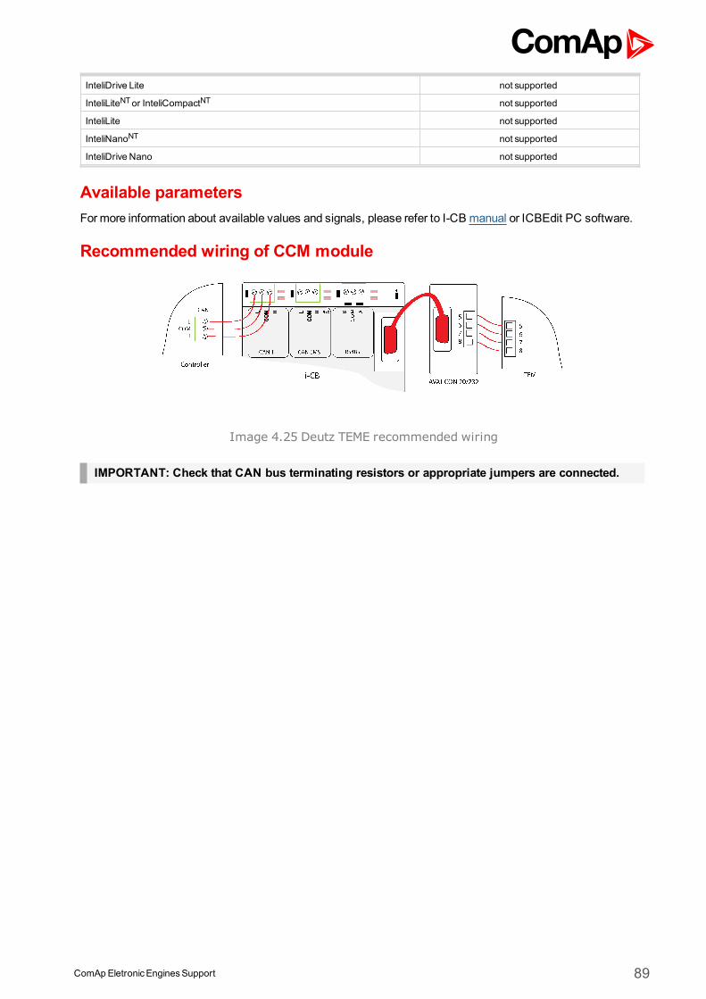
ComApEletronicEnginesSupport 89
InteliDrive Lite not supported
InteliLiteNTor InteliCompactNT not supported
InteliLite not supported
InteliNanoNT not supported
InteliDrive Nano not supported
Available parametersFormore information about available values and signals, please refer to I-CB manual or ICBEdit PC software.
Recommended wiring of CCM module
Image 4.25 Deutz TEME recommended wiring
IMPORTANT: Check that CAN bus terminating resistors or appropriate jumpers are connected.
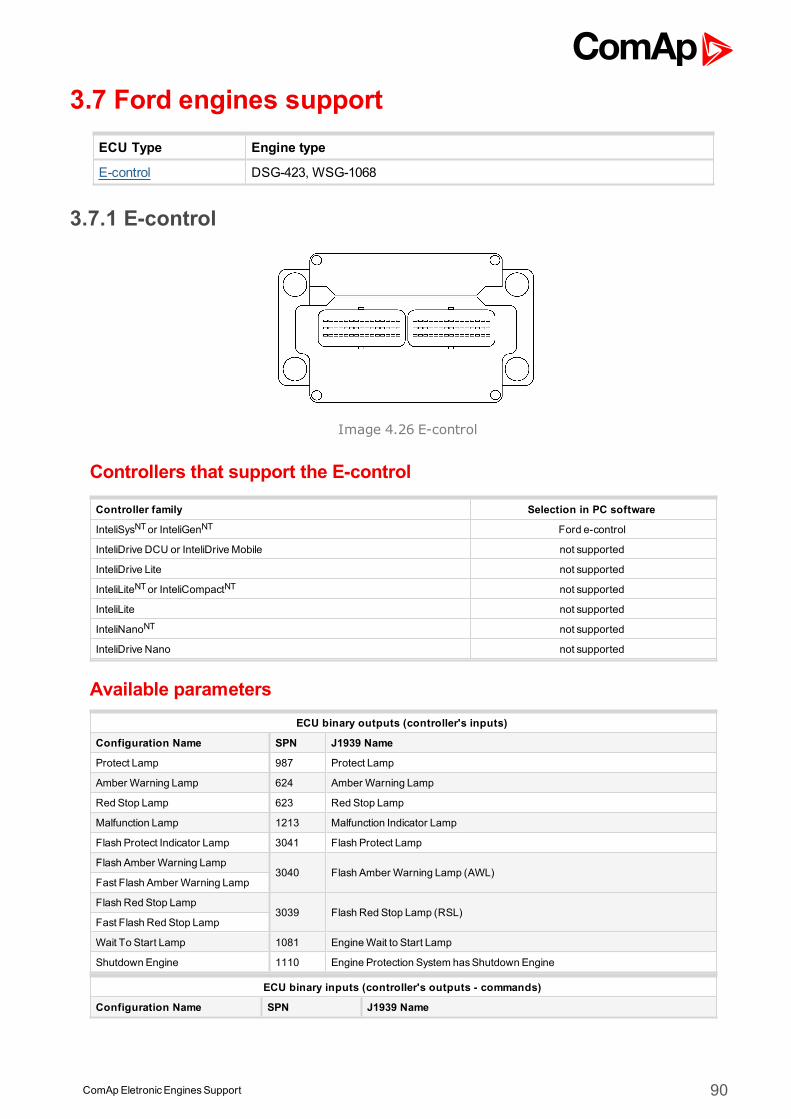
ComApEletronicEnginesSupport 90
3.7 Ford engines supportECU Type Engine type
E-control DSG-423, WSG-1068
3.7.1 E-control
Image 4.26 E-control
Controllers that support the E-control
Controller family Selection in PC software
InteliSysNTor InteliGenNT Ford e-control
InteliDrive DCU or InteliDriveMobile not supported
InteliDrive Lite not supported
InteliLiteNTor InteliCompactNT not supported
InteliLite not supported
InteliNanoNT not supported
InteliDrive Nano not supported
Available parametersECU binary outputs (controller's inputs)
Configuration Name SPN J1939 Name
Protect Lamp 987 Protect Lamp
Amber Warning Lamp 624 Amber Warning Lamp
Red Stop Lamp 623 Red Stop Lamp
Malfunction Lamp 1213 Malfunction Indicator Lamp
Flash Protect Indicator Lamp 3041 Flash Protect Lamp
Flash Amber Warning Lamp3040 Flash Amber Warning Lamp (AWL)
Fast Flash Amber Warning Lamp
Flash Red Stop Lamp3039 Flash Red Stop Lamp (RSL)
Fast Flash Red Stop Lamp
Wait To Start Lamp 1081 EngineWait to Start Lamp
Shutdown Engine 1110 Engine Protection System hasShutdown Engine
ECU binary inputs (controller's outputs - commands)
Configuration Name SPN J1939 Name
ComApEletronicEnginesSupport 91
ECU analog outputs (controller's inputs)
Configuration Name SPN J1939 Name
Engine speed 190 Engine Speed
Engine torque 513 ActualEngine - Percent Torque
Coolant Temp 110 Engine Coolant Temperature
EngineOil Temp 175 EngineOil Temperature 1
Intercooler Temp 52 Engine Intercooler Temperature
Boost Pressure 102 Engine IntakeManifold #1 Pressure
IntakeManifold Temp 105 Engine IntakeManifold 1 Temperature
Air Inlet Pressure 106 Engine Intake Air Pressure
AccPedal 1 Low Idle Switch 558 Accelerator Pedal 1 Low Idle Switch
Accelerator PedalPosition 91 Accelerator PedalPosition 1
Load At Current Speed 92 Engine Percent Load At Current Speed
Accelerator PedalPosition2 29 Accelerator PedalPosition 2
FuelRate 183 Engine FuelRate
Throttle Position 51 Engine Throttle Valve 1 Position 1
ElectricalPotential (Voltage) 168 BatteryPotential / Power Input 1
BatteryPotential (Voltage) 158 Keyswitch BatteryPotential
EngineOil Level 98 EngineOil Level
EngineOil Pressure 100 EngineOil Pressure
BarometricPressure 108 BarometricPressure
Air Inlet Temperature 172 Engine Intake Air Temperature
ECU analog inputs (controller's outputs)
Configuration Name SPN J1939 Name
Requested speed 898 Engine Requested Speed/Speed Limit
Supported parameter by the controllers configured byNanoEdit, DriveEdit or LiteEdit PC software:
1 - InteliLiteNT, 2 - InteliLite , 3 - InteliDrive Lite , 4 - InteliCompactNT, 5 - InteliNanoNT, 6 - InteliDrive Nano
Controller’s analog output for speed control configurationRequested speed settings for InteliGenNT or InteliSysNT
Source SpeedReq RPM
Convert NO
LimitsN/A N/A
N/A N/A
Requested speed settings for InteliDrive DCU, InteliDrive Mobile
Source SpeedReq RPM
Convert NO
Limits0.0 % Min eng. speed (800RPM)
100.0 % Max eng. speed (2100RPM)
Recommended wiring
Function ECU B connectorcustomer 42pin
connectorController
CAN H 14 28 CAN1 (extension modules/J1939) – CANH
CAN COM N/A N/ACAN1 (extensionmodules/J1939) – CAN
COM
ComApEletronicEnginesSupport 92
CAN L 15 29 CAN1 (extension modules/J1939) – CANL
Battery + (positive) 60,79 N/A N/A
Battery - (negative) 4,69,81 N/A N/A
Key Switch N/A N/AAnybinary output configured asECU
PwrRelay
Analog Speed Control N/A N/A SG OUT
Analog Speed Control N/A N/A SGCOM
Formore information about diagnostic connector layout see SAE - J1939 diagnostic connector on page 17.Available list of texts of fault codes see E-control on page 259.
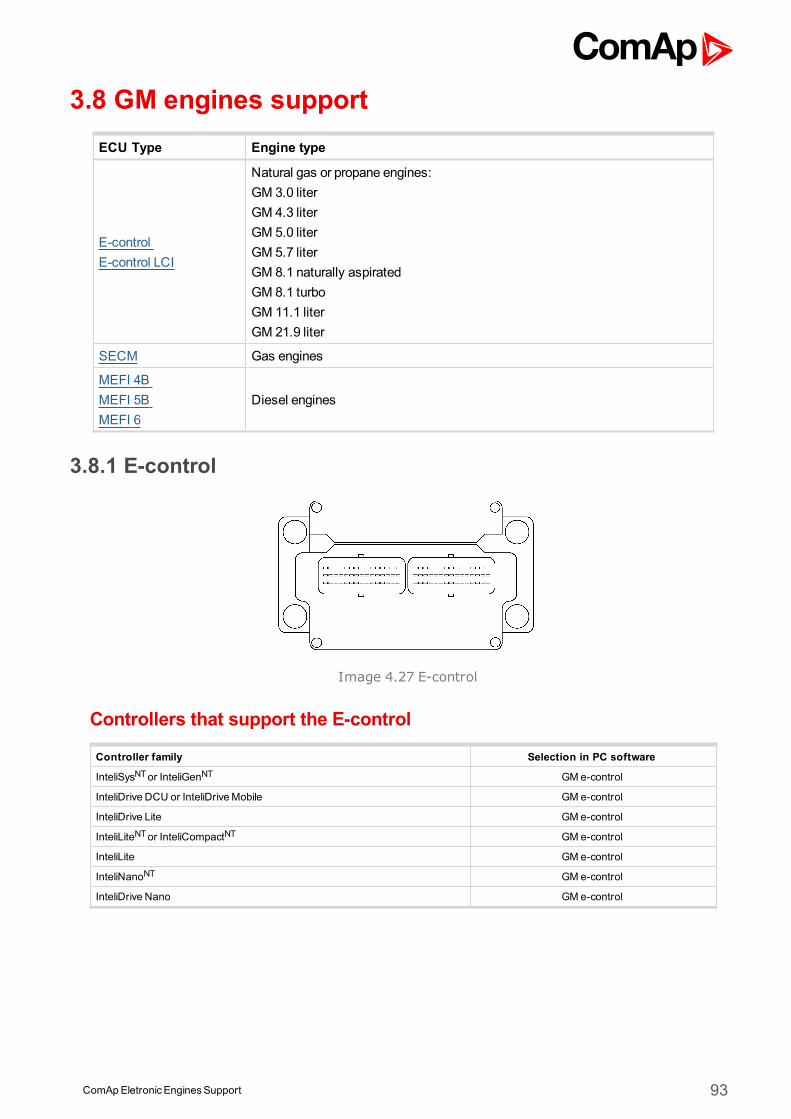
ComApEletronicEnginesSupport 93
3.8 GM engines supportECU Type Engine type
E-controlE-control LCI
Natural gas or propane engines:GM 3.0 literGM 4.3 literGM 5.0 literGM 5.7 literGM 8.1 naturally aspiratedGM 8.1 turboGM 11.1 literGM 21.9 liter
SECM Gas engines
MEFI 4BMEFI 5BMEFI 6
Diesel engines
3.8.1 E-control
Image 4.27 E-control
Controllers that support the E-control
Controller family Selection in PC software
InteliSysNTor InteliGenNT GMe-control
InteliDrive DCU or InteliDriveMobile GM e-control
InteliDrive Lite GM e-control
InteliLiteNTor InteliCompactNT GMe-control
InteliLite GM e-control
InteliNanoNT GMe-control
InteliDrive Nano GM e-control
ComApEletronicEnginesSupport 94
Available parametersECU binary outputs (controller's inputs)
Configuration Name SPN J1939 Name
Protect Lamp 987 Protect Lamp
Amber Warning Lamp 624 Amber Warning Lamp
Red Stop Lamp 623 Red Stop Lamp
Malfunction Lamp 1213 Malfunction Indicator Lamp
Flash Protect Indicator Lamp 3041 Flash Protect Lamp
Flash Amber Warning Lamp
3040 Flash Amber Warning Lamp (AWL)Fast Flash Amber WarningLamp
Flash Red Stop Lamp3039 Flash Red Stop Lamp (RSL)
Fast Flash Red Stop Lamp
Wait To Start Lamp 1081 EngineWait to Start Lamp
Shutdown Engine 1110 Engine Protection System hasShutdown Engine
ECU binary outputs (controller's inputs)
Configuration Name SPN J1939 Name
ECU binary outputs (controller's inputs)
Configuration Name SPN J1939 Name
Engine speed 190 Engine Speed
Engine torque 513 ActualEngine - Percent Torque
Coolant Temp 110 Engine Coolant Temperature
EngineOil Temp 175 EngineOil Temperature 1
Intercooler Temp 52 Engine Intercooler Temperature
Boost Pressure 102 Engine IntakeManifold #1 Pressure
IntakeManifold Temp 105 Engine IntakeManifold 1 Temperature
Air Inlet Pressure 106 Engine Intake Air Pressure
AccPedal 1 Low Idle Switch 558 Accelerator Pedal 1 Low Idle Switch
Accelerator PedalPosition 91 Accelerator PedalPosition 1
Load At Current Speed 92 Engine Percent Load At Current Speed
Accelerator PedalPosition2 29 Accelerator PedalPosition 2
FuelRate 183 Engine FuelRate
Throttle Position 51 Engine Throttle Valve 1 Position 1
TotalEngine Hours 247 Engine TotalHours of Operation
ElectricalPotential (Voltage) 168 BatteryPotential / Power Input 1
BatteryPotential (Voltage) 158 Keyswitch BatteryPotential
EngineOil Level 98 EngineOil Level
EngineOil Pressure 100 EngineOil Pressure
BarometricPressure 108 BarometricPressure
Air Inlet Temperature 172 Engine Intake Air Temperature
ECU binary outputs (controller's inputs)
Configuration Name SPN J1939 Name
Requested speed 1,2,3,4,5,6 898 Engine Requested Speed/Speed Limit
Supported parameter by the controllers configured byNanoEdit, DriveEdit or LiteEdit PC software:
1 - InteliLiteNT, 2 - InteliLite , 3 - InteliDrive Lite , 4 - InteliCompactNT, 5 - InteliNanoNT, 6 - InteliDrive Nano
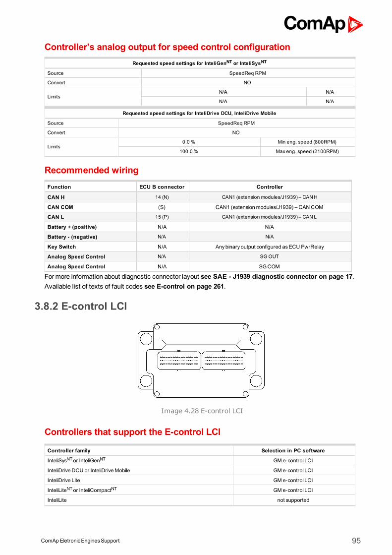
ComApEletronicEnginesSupport 95
Controller’s analog output for speed control configurationRequested speed settings for InteliGenNT or InteliSysNT
Source SpeedReq RPM
Convert NO
LimitsN/A N/A
N/A N/A
Requested speed settings for InteliDrive DCU, InteliDrive Mobile
Source SpeedReq RPM
Convert NO
Limits0.0 % Min eng. speed (800RPM)
100.0 % Max eng. speed (2100RPM)
Recommended wiringFunction ECU B connector Controller
CAN H 14 (N) CAN1 (extension modules/J1939) – CANH
CAN COM (S) CAN1 (extensionmodules/J1939) – CAN COM
CAN L 15 (P) CAN1 (extension modules/J1939) – CANL
Battery + (positive) N/A N/A
Battery - (negative) N/A N/A
Key Switch N/A Anybinary output configured asECU PwrRelay
Analog Speed Control N/A SG OUT
Analog Speed Control N/A SGCOM
Formore information about diagnostic connector layout see SAE - J1939 diagnostic connector on page 17.Available list of texts of fault codes see E-control on page 261.
3.8.2 E-control LCI
Image 4.28 E-control LCI
Controllers that support the E-control LCI
Controller family Selection in PC software
InteliSysNTor InteliGenNT GMe-control LCI
InteliDrive DCU or InteliDriveMobile GM e-control LCI
InteliDrive Lite GM e-control LCI
InteliLiteNTor InteliCompactNT GMe-control LCI
InteliLite not supported
ComApEletronicEnginesSupport 96
InteliNanoNT not supported
InteliDrive Nano GM e-control LCI
Available parametersECU binary outputs (controller's inputs)
Configuration Name SPN J1939 Name
Protect Lamp 987 Protect Lamp
Amber Warning Lamp 624 Amber Warning Lamp
Red Stop Lamp 623 Red Stop Lamp
Malfunction Lamp 1213 Malfunction Indicator Lamp
Flash Protect Indicator Lamp 3041 Flash Protect Lamp
Flash Amber Warning Lamp
3040 Flash Amber Warning Lamp (AWL)Fast Flash Amber WarningLamp
Flash Red Stop Lamp3039 Flash Red Stop Lamp (RSL)
Fast Flash Red Stop Lamp
Wait To Start Lamp 1081 EngineWait to Start Lamp
Shutdown Engine 1110 Engine Protection System hasShutdown Engine
ECU binary outputs (controller's inputs)
Configuration Name SPN J1939 Name
ECU binary outputs (controller's inputs)
Configuration Name SPN J1939 Name
Engine speed 190 Engine Speed
Engine torque 513 ActualEngine - Percent Torque
Percent Load 92 Engine Percent Load At Current Speed
Coolant Temp 110 Engine Coolant Temperature
EngineOil Temp 175 EngineOil Temperature 1
Intercooler Temp 52 Engine Intercooler Temperature
Boost Pressure 102 Engine IntakeManifold #1 Pressure
IntakeManifold Temp 105 Engine IntakeManifold 1 Temperature
Air Inlet Pressure 106 Engine Intake Air Pressure
FuelRate 183 Engine FuelRate
Throttle Position 51 Engine Throttle Valve 1 Position 1
ElectricalPotential (Voltage) 168 BatteryPotential / Power Input 1
BatteryPotential (Voltage) 158 Keyswitch BatteryPotential
EngineOil Level 98 EngineOil Level
EngineOil Pressure 100 EngineOil Pressure
BarometricPressure 108 BarometricPressure
Air Inlet Temperature 172 Engine Intake Air Temperature
ECU binary outputs (controller's inputs)
Configuration Name SPN J1939 Name
Requested speed 1,2,3,4,6 898 Engine Requested Speed/Speed Limit
Supported parameter by the controllers configured byNanoEdit, DriveEdit or LiteEdit PC software:
1 - InteliLiteNT, 2 - InteliLite , 3 - InteliDrive Lite , 4 - InteliCompactNT, 5 - InteliNanoNT, 6 - InteliDrive Nano
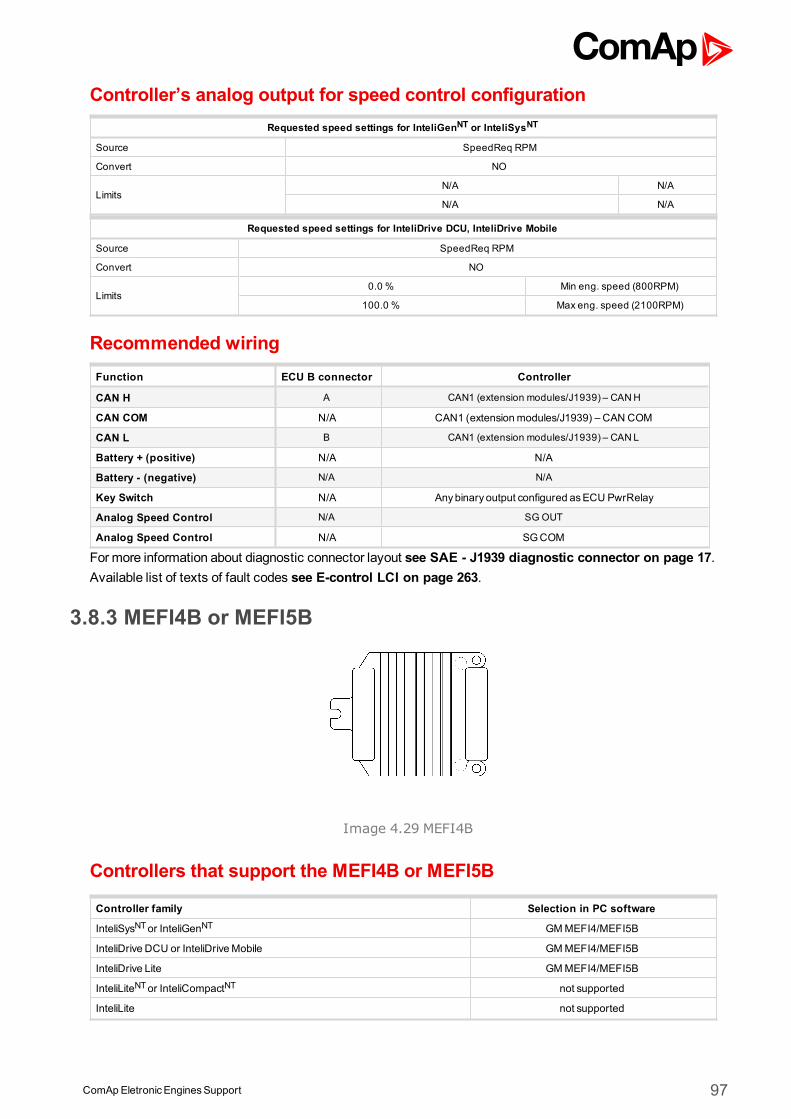
ComApEletronicEnginesSupport 97
Controller’s analog output for speed control configurationRequested speed settings for InteliGenNT or InteliSysNT
Source SpeedReq RPM
Convert NO
LimitsN/A N/A
N/A N/A
Requested speed settings for InteliDrive DCU, InteliDrive Mobile
Source SpeedReq RPM
Convert NO
Limits0.0 % Min eng. speed (800RPM)
100.0 % Max eng. speed (2100RPM)
Recommended wiringFunction ECU B connector Controller
CAN H A CAN1 (extension modules/J1939) – CANH
CAN COM N/A CAN1 (extensionmodules/J1939) – CAN COM
CAN L B CAN1 (extension modules/J1939) – CANL
Battery + (positive) N/A N/A
Battery - (negative) N/A N/A
Key Switch N/A Anybinary output configured asECU PwrRelay
Analog Speed Control N/A SG OUT
Analog Speed Control N/A SGCOM
Formore information about diagnostic connector layout see SAE - J1939 diagnostic connector on page 17.Available list of texts of fault codes see E-control LCI on page 263.
3.8.3 MEFI4B or MEFI5B
Image 4.29 MEFI4B
Controllers that support the MEFI4B or MEFI5B
Controller family Selection in PC software
InteliSysNTor InteliGenNT GMMEFI4/MEFI5B
InteliDrive DCU or InteliDriveMobile GMMEFI4/MEFI5B
InteliDrive Lite GMMEFI4/MEFI5B
InteliLiteNTor InteliCompactNT not supported
InteliLite not supported
ComApEletronicEnginesSupport 98
InteliNanoNT not supported
InteliDrive Nano GMMEFI4/MEFI5B
Available parametersECU binary outputs (controller's inputs)
Configuration Name SPN J1939 Name
Protect Lamp 987 Protect Lamp
Amber Warning Lamp 624 Amber Warning Lamp
Red Stop Lamp 623 Red Stop Lamp
Malfunction Lamp 1213 Malfunction Indicator Lamp
Flash Protect Indicator Lamp 3041 Flash Protect Lamp
Flash Amber Warning Lamp
3040 Flash Amber Warning Lamp (AWL)Fast Flash Amber WarningLamp
Flash Red Stop Lamp3039 Flash Red Stop Lamp (RSL)
Fast Flash Red Stop Lamp
Protect Lamp prop - Proprietary parameter.
Amber Warning Lamp prop - Proprietary parameter.
Red Stop Lamp prop - Proprietary parameter.
Malfunction Lamp prop - Proprietary parameter.
Wait To Start Lamp 1081 EngineWait to Start Lamp
ECU binary outputs (controller's inputs)
Configuration Name SPN J1939 Name
ECU binary outputs (controller's inputs)
Configuration Name SPN J1939 Name
Engine speed 190 Engine Speed
Coolant Temp 110 Engine Coolant Temperature
Boost Pressure (MEFI5Bonly)
102 Engine IntakeManifold #1 Pressure
IntakeManifold Temp(MEFI5B only)
105 Engine IntakeManifold 1 Temperature
Air Intake Pressure (MEFI5Bonly)
106 Engine Intake Air Pressure
Exhaust GasTemp (MEFI5Bonly)
173 Engine Exhaust Temperature
Accelerator PedalPosition 91 Accelerator PedalPosition 1
Percent Load 92 Engine Percent Load At Current Speed
FuelRate (MEFI5B only) 183 Engine FuelRate
Fuel Level (MEFI5B only) 96 Fuel Level 1
BatteryPotential (Voltage) 158 Keyswitch BatteryPotential
FuelDeliveryPressure 94 Engine FuelDeliveryPressure
EngineOil Level 98 EngineOil Level
EngineOil Pressure 100 EngineOil Pressure
ECU binary outputs (controller's inputs)
Configuration Name SPN J1939 Name
Requested speed 3,6 898 Engine Requested Speed/Speed Limit
Supported parameter by the controllers configured byNanoEdit, DriveEdit or LiteEdit PC software:
1 - InteliLiteNT, 2 - InteliLite , 3 - InteliDrive Lite , 4 - InteliCompactNT, 5 - InteliNanoNT, 6 - InteliDrive Nano
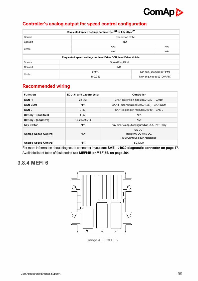
ComApEletronicEnginesSupport 99
Controller’s analog output for speed control configurationRequested speed settings for InteliGenNT or InteliSysNT
Source SpeedReq RPM
Convert NO
LimitsN/A N/A
N/A N/A
Requested speed settings for InteliDrive DCU, InteliDrive Mobile
Source SpeedReq RPM
Convert NO
Limits0.0 % Min eng. speed (800RPM)
100.0 % Max eng. speed (2100RPM)
Recommended wiringFunction ECU J1 and J2connector Controller
CAN H 24 (J2) CAN1 (extension modules/J1939) – CANH
CAN COM N/A CAN1 (extensionmodules/J1939) – CAN COM
CAN L 9 (J2) CAN1 (extension modules/J1939) – CANL
Battery + (positive) 1 (J2) N/A
Battery - (negative) 13,28,29 (J1) N/A
Key Switch N/A Anybinary output configured asECU PwrRelay
Analog Speed Control N/ASG OUT
Range 0VDC to 5VDC,100kOhmpull-down resistance
Analog Speed Control N/A SGCOM
Formore information about diagnostic connector layout see SAE - J1939 diagnostic connector on page 17.Available list of texts of fault codes see MEFI4B or MEFI5B on page 264.
3.8.4 MEFI 6
Image 4.30 MEFI 6
ComApEletronicEnginesSupport 100
Controllers that support the MEFI 6
Controller family Selection in PC software
InteliSysNTor InteliGenNT GMMEFI6
InteliDrive DCU or InteliDriveMobile GMMEFI6
InteliDrive Lite GMMEFI6
InteliLiteNTor InteliCompactNT GMMEFI6
InteliLite GMMEFI6
InteliNanoNT GMMEFI6
InteliDrive Nano GMMEFI6
Available parametersECU binary outputs (controller's inputs)
Configuration Name SPN J1939 Name
Protect Lamp 987 Protect Lamp
Amber Warning Lamp 624 Amber Warning Lamp
Red Stop Lamp 623 Red Stop Lamp
Malfunction Lamp 1213 Malfunction Indicator Lamp
Flash Protect Indicator Lamp 3041 Flash Protect Lamp
Flash Amber Warning Lamp
3040 Flash Amber Warning Lamp (AWL)Fast Flash Amber WarningLamp
Flash Red Stop Lamp3039 Flash Red Stop Lamp (RSL)
Fast Flash Red Stop Lamp
MEFI6 Protect Lamp - Proprietary parameter.
MEFI6 Amber Warning Lamp- Proprietary parameter.
MEFI6 Red Stop Lamp - Proprietary parameter.
MEFI6Malfunction Lamp - Proprietary parameter.
Wait To Start Lamp 1081 EngineWait to Start Lamp
ECU binary outputs (controller's inputs)
Configuration Name SPN J1939 Name
ECU binary outputs (controller's inputs)
Configuration Name SPN J1939 Name
Engine speed 190 Engine Speed
Actual Torque 513 ActualEngine - Percent Torque
StarterMode 1678 Cab Ventilation
APPosition 91 Accelerator PedalPosition 1
Percent Load 92 Engine Percent Load At Current Speed
Desired speed 515 Engine'sDesired Operating Speed
Coolant Temp 110 Engine Coolant Temperature
Oil Temperature 175 EngineOil Temperature 1
FuelDeliveryPressure 94 Engine FuelDeliveryPressure
Oil Pressure 100 EngineOil Pressure
FuelRate 183 Engine FuelRate
BarometricPressure 103 Engine Turbocharger 1 Speed
ComApEletronicEnginesSupport 101
Boost Pressure 102 Engine IntakeManifold #1 Pressure
IntakeManifold Temp 105 Engine IntakeManifold 1 Temperature
Air Intake Pressure 106 Engine Intake Air Pressure
BatteryPotential 168 BatteryPotential / Power Input 1
Fuel Level 96 Fuel Level 1
ECU binary outputs (controller's inputs)
Configuration Name SPN J1939 Name
Requested speed 1,2,3,4,5,6 - Proprietary parameter.
TSC1Requested speed 898 Engine Requested Speed/Speed Limit
Supported parameter by the controllers configured byNanoEdit, DriveEdit or LiteEdit PC software:
1 - InteliLiteNT, 2 - InteliLite , 3 - InteliDrive Lite , 4 - InteliCompactNT, 5 - InteliNanoNT, 6 - InteliDrive Nano
Controller’s analog output for speed control configurationRequested speed settings for InteliGenNT or InteliSysNT
Source SpeedReq RPM
Convert NO
LimitsN/A N/A
N/A N/A
Requested speed settings for InteliDrive DCU, InteliDrive Mobile
Source SpeedReq RPM
Convert NO
Limits0.0 % Min eng. speed (800RPM)
100.0 % Max eng. speed (2100RPM)
Recommended wiringNo documentation available so far!
For more information about diagnostic connector layout see SAE - J1939 diagnostic connector on page 17.Available list of texts of fault codes see MEFI 6 on page 266.
3.8.5 SECM
Image 4.31 SECM
ComApEletronicEnginesSupport 102
Controllers that support the SECM
Controller family Selection in PC software
InteliSysNTor InteliGenNT GMSECM
InteliDrive DCU or InteliDriveMobile GMSECM
InteliDrive Lite GMSECM
InteliLiteNTor InteliCompactNT GMSECM
InteliLite GMSECM
InteliNanoNT GMSECM
InteliDrive Nano GMSECM
Available parametersECU binary outputs (controller's inputs)
Configuration Name SPN J1939 Name
Protect Lamp 987 Protect Lamp
Amber Warning Lamp 624 Amber Warning Lamp
Red Stop Lamp 623 Red Stop Lamp
Malfunction Lamp 1213 Malfunction Indicator Lamp
Flash Protect Indicator Lamp 3041 Flash Protect Lamp
Flash Amber Warning Lamp
3040 Flash Amber Warning Lamp (AWL)Fast Flash Amber WarningLamp
Flash Red Stop Lamp3039 Flash Red Stop Lamp (RSL)
Fast Flash Red Stop Lamp
Shutdown Engine 1110 Engine Protection System hasShutdown Engine
Approaching Shutdown 1109 Engine Protection SystemApproaching Shutdown
System Timer State 1107 Engine Protection System Timer State
SystemConfiguration 1111 Engine Protection SystemConfiguration
Wait To Start Lamp 1081 EngineWait to Start Lamp
ECU binary outputs (controller's inputs)
Configuration Name SPN J1939 Name
ECU binary outputs (controller's inputs)
Configuration Name SPN J1939 Name
Engine speed 190 Engine Speed
Coolant Temp 110 Engine Coolant Temperature
Fuel Temp 174 Engine Fuel Temperature 1
EngineOil Temp 175 EngineOil Temperature 1
Boost Pressure 102 Engine IntakeManifold #1 Pressure
IntakeManifold Temp 105 Engine IntakeManifold 1 Temperature
Accelerator PedalPosition 91 Accelerator PedalPosition 1
Percent Load 92 Engine Percent Load At Current Speed
Engine Throttle Position 109 Engine Coolant Pressure 1
FuelRate 183 Engine FuelRate
BatteryPotential (Voltage) 158 Keyswitch BatteryPotential
EngineOil Pressure 100 EngineOil Pressure
BarometricPressure 108 BarometricPressure
Inlet Air MassFlow Rate 132 Engine Intake Air MassFlow Rate
ComApEletronicEnginesSupport 103
ECU binary outputs (controller's inputs)
Configuration Name SPN J1939 Name
Requested speed 1,2,3,4,5,6 898 Engine Requested Speed/Speed Limit
Supported parameter by the controllers configured byNanoEdit, DriveEdit or LiteEdit PC software:
1 - InteliLiteNT, 2 - InteliLite , 3 - InteliDrive Lite , 4 - InteliCompactNT, 5 - InteliNanoNT, 6 - InteliDrive Nano
Controller’s analog output for speed control configurationRequested speed settings for InteliGenNT or InteliSysNT
Source SpeedReq RPM
Convert NO
LimitsN/A N/A
N/A N/A
Requested speed settings for InteliDrive DCU, InteliDrive Mobile
Source SpeedReq RPM
Convert NO
Limits0.0 % Min eng. speed (800RPM)
100.0 % Max eng. speed (2100RPM)
Recommended wiringFunction ECU B connector Controller
CAN H 20 CAN1 (extension modules/J1939) – CANH
CAN COM N/A CAN1 (extensionmodules/J1939) – CAN COM
CAN L 21 CAN1 (extension modules/J1939) – CANL
Battery + (positive) 22 N/A
Battery - (negative) 17 N/A
Key Switch N/A Anybinary output configured asECU PwrRelay
Analog Speed Control N/ASG OUT
Range 0VDC to 5VDC,100kOhmpull-down resistance
Analog Speed Control N/A SGCOM
Formore information about diagnostic connector layout see SAE - J1939 diagnostic connector on page 17.Available list of texts of fault codes see SECM on page 268.
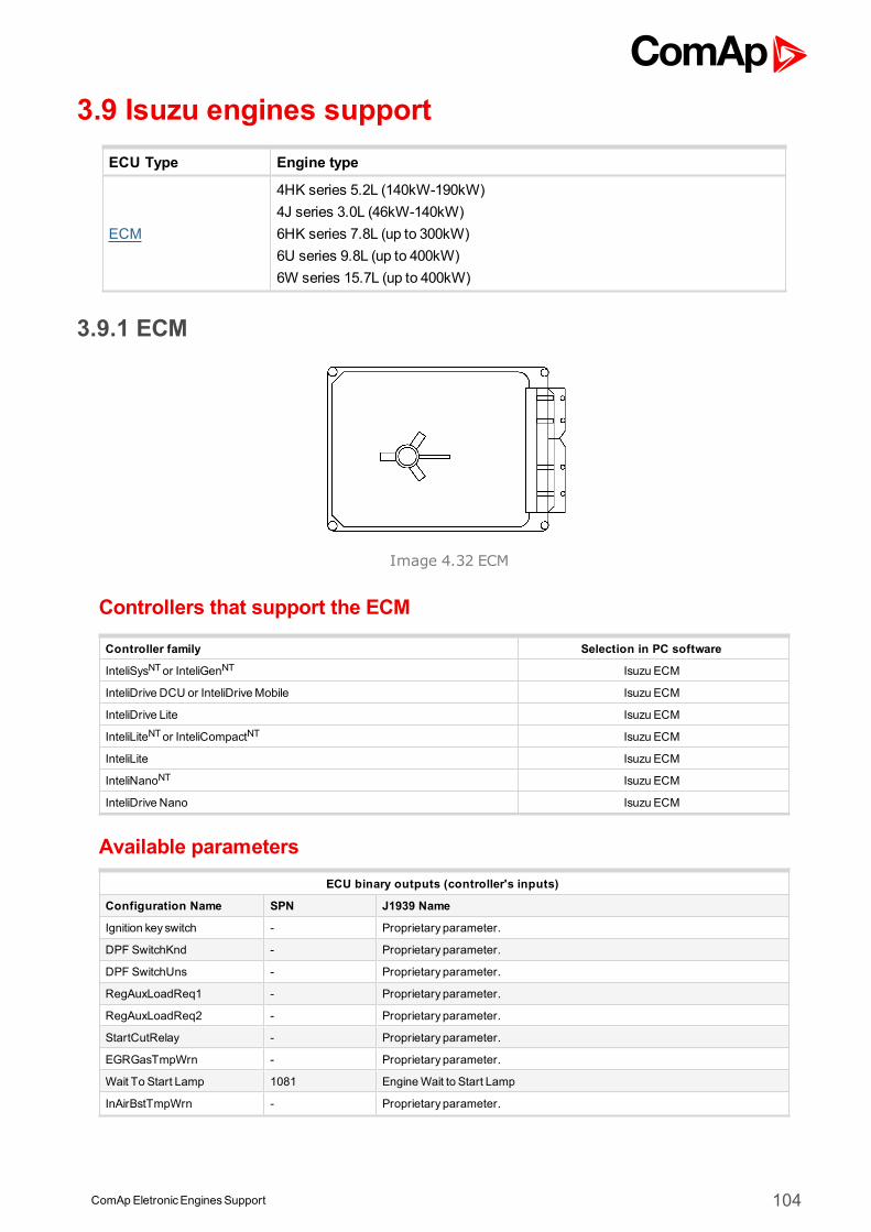
ComApEletronicEnginesSupport 104
3.9 Isuzu engines supportECU Type Engine type
ECM
4HK series 5.2L (140kW-190kW)4J series 3.0L (46kW-140kW)6HK series 7.8L (up to 300kW)6U series 9.8L (up to 400kW)6W series 15.7L (up to 400kW)
3.9.1 ECM
Image 4.32 ECM
Controllers that support the ECM
Controller family Selection in PC software
InteliSysNTor InteliGenNT Isuzu ECM
InteliDrive DCU or InteliDriveMobile Isuzu ECM
InteliDrive Lite Isuzu ECM
InteliLiteNTor InteliCompactNT Isuzu ECM
InteliLite Isuzu ECM
InteliNanoNT Isuzu ECM
InteliDrive Nano Isuzu ECM
Available parametersECU binary outputs (controller's inputs)
Configuration Name SPN J1939 Name
Ignition key switch - Proprietary parameter.
DPF SwitchKnd - Proprietary parameter.
DPF SwitchUns - Proprietary parameter.
RegAuxLoadReq1 - Proprietary parameter.
RegAuxLoadReq2 - Proprietary parameter.
StartCutRelay - Proprietary parameter.
EGRGasTmpWrn - Proprietary parameter.
Wait To Start Lamp 1081 EngineWait to Start Lamp
InAirBstTmpWrn - Proprietary parameter.
ComApEletronicEnginesSupport 105
ExhstGasTmpWrn - Proprietary parameter.
IntAirTmpWrn - Proprietary parameter.
FuelFltrClogg - Proprietary parameter.
EngOilPresDrop - Proprietary parameter.
BoostTmpRise - Proprietary parameter.
FuelTmpRise - Proprietary parameter.
ClntTmpRise - Proprietary parameter.
OverrunWrn - Proprietary parameter.
EmerSDoperSig - Proprietary parameter.
Glow signal - Proprietary parameter.
StarterSwitch 704 Auxiliary I/O#04
DPF GrLampMode - Proprietary parameter.
DPF RegLampReq - Proprietary parameter.
DPF BuzzerMode - Proprietary parameter.
DPF RegenFlag - Proprietary parameter.
Protect Lamp 987 Protect Lamp
Amber Warning Lamp 624 Amber Warning Lamp
Red Stop Lamp 623 Red Stop Lamp
Malfunction Lamp 1213 Malfunction Indicator Lamp
Flash Protect Indicator Lamp 3041 Flash Protect Lamp
Flash Amber Warning Lamp
3040 Flash Amber Warning Lamp (AWL)Fast Flash Amber WarningLamp
Flash Red Stop Lamp3039 Flash Red Stop Lamp (RSL)
Fast Flash Red Stop Lamp
ECU binary outputs (controller's inputs)
Configuration Name SPN J1939 Name
Stop Request 1,2,3,4,5,6 -Proprietary parameter.The command for normal stopping of the engine. The recommended sourcevalue for this command isStop solenoid.
EngProtHoldSig -Proprietary parameter.Engine Protection SystemHolding Signal. For more information about thissignal contact local Isuzu representative
PreheatStartSg -Proprietary parameter.Preheating Start Signal. For more information about this signal contact localIsuzu representative
ECU binary outputs (controller's inputs)
Configuration Name SPN J1939 Name
Engine speed 190 Engine Speed
Actual Torque 513 ActualEngine - Percent Torque
Demand Torque 512 Driver'sDemand Engine - Percent Torque
Coolant Temp 110 Engine Coolant Temperature
Fuel Temperature 174 Engine Fuel Temperature 1
EngineOil Temp 175 EngineOil Temperature 1
Boost temp - Proprietary parameter.
Boost Pressure - Proprietary parameter.
IntakeManifold Temp - Proprietary parameter.
DPF filter Inlet GasTemp - Proprietary parameter.
ComApEletronicEnginesSupport 106
Catalyst inlet gas temp - Proprietary parameter.
EGR gas temp - Proprietary parameter.
Accelerator PedalPosition 91 Accelerator PedalPosition 1
Percent Load 92 Engine Percent Load At Current Speed
Remote Accelerator PedalPosition
974 Remote Accelerator PedalPosition
FuelRate 183 Engine FuelRate
EngOil Filter Diff.Press 99 EngineOil Filter Differential Pressure
Main relay voltage 168 BatteryPotential / Power Input 1
BatteryPotential (Voltage) 158 Keyswitch BatteryPotential
FuelDeliveryPressure 94 Engine FuelDeliveryPressure
EngineOil Level 98 EngineOil Level
EngineOil Pressure 100 EngineOil Pressure
Crankcase Pressure 101 Engine Crankcase Pressure 1
Coolant Pressure 109 Engine Coolant Pressure 1
Coolant Level 111 Engine Coolant Level 1
Target engine speed - Proprietary parameter.
Fuel injection quantity level - Proprietary parameter.
Engine percent torque - Proprietary parameter.
DiffPressJudg1 164 Engine Injection Control Pressure
Commonrail Pressure 157 Engine Injector Metering Rail 1 Pressure
Instruction engine speed - Proprietary parameter.
CommonrailDiff Pressure - Proprietary parameter.
DPF AmLampMode - Proprietary parameter.
DPF IndiStat - Proprietary parameter.
Atmospheric pressure 108 BarometricPressure
T-Ambient 172 Engine Intake Air Temperature
PCode - Proprietary parameter.
Turbo actual opening - Proprietary parameter.
ECU binary outputs (controller's inputs)
Configuration Name SPN J1939 Name
Requested speed 1,2,3,4,5,6 898 Engine Requested Speed/Speed Limit
EngineModel/SN - Proprietary parameter.
Supported parameter by the controllers configured byNanoEdit, DriveEdit or LiteEdit PC software:
1 - InteliLiteNT, 2 - InteliLite , 3 - InteliDrive Lite , 4 - InteliCompactNT, 5 - InteliNanoNT, 6 - InteliDrive Nano
Controller’s analog output for speed control configurationRequested speed settings for InteliGenNT or InteliSysNT
Source SpeedReq RPM
Convert NO
LimitsN/A N/A
N/A N/A
Requested speed settings for InteliDrive DCU, InteliDrive Mobile
Source SpeedReq RPM
Convert NO
Limits0.0 % Min eng. speed (800RPM)
100.0 % Max eng. speed (2100RPM)
ComApEletronicEnginesSupport 107
Recommended wiringFunction ECU 121pin connector Controller
CAN H 18 CAN1 (extension modules/J1939) – CANH
CAN COM N/A CAN1 (extensionmodules/J1939) – CAN COM
CAN L 37 CAN1 (extension modules/J1939) – CANL
Battery + (positive) 2,5 N/A
Battery - (negative) 1,3,4 N/A
Key Switch 24 Anybinary output configured asECU PwrRelay
Analog Speed Control N/ASG OUT
Range 0VDC to 5VDC,100kOhmpull-down resistance
Analog Speed Control N/A SGCOM
Formore information about diagnostic connector layout see SAE - J1939 diagnostic connector on page 17.Available list of texts of fault codes see ECM on page 269.
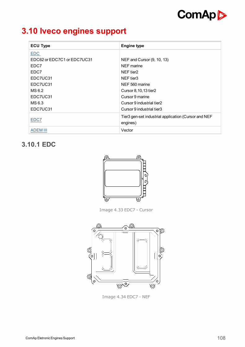
ComApEletronicEnginesSupport 108
3.10 Iveco engines supportECU Type Engine type
EDCEDC62 or EDC7C1 or EDC7UC31EDC7EDC7EDC7UC31EDC7UC31MS 6.2EDC7UC31MS 6.3EDC7UC31
NEF and Cursor (9, 10, 13)NEFmarineNEF tier2NEF tier3NEF 560marineCursor 8,10,13 tier2Cursor 9marineCursor 9 industrial tier2Cursor 9 industrial tier3
EDC7Tier3 gen-set industrial application (Cursor and NEFengines)
ADEM III Vector
3.10.1 EDC
Image 4.33 EDC7 - Cursor
Image 4.34 EDC7 - NEF
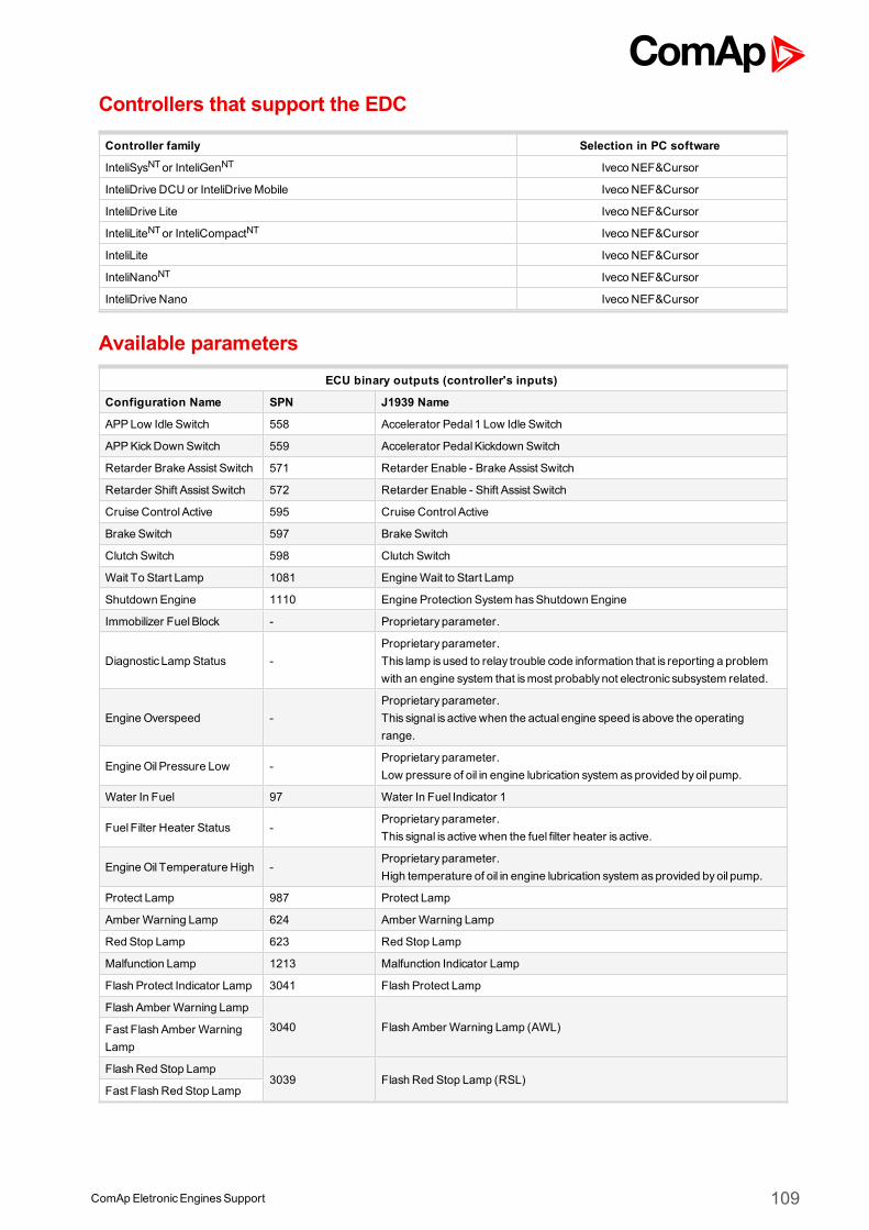
ComApEletronicEnginesSupport 109
Controllers that support the EDC
Controller family Selection in PC software
InteliSysNTor InteliGenNT Iveco NEF&Cursor
InteliDrive DCU or InteliDriveMobile Iveco NEF&Cursor
InteliDrive Lite Iveco NEF&Cursor
InteliLiteNTor InteliCompactNT Iveco NEF&Cursor
InteliLite Iveco NEF&Cursor
InteliNanoNT Iveco NEF&Cursor
InteliDrive Nano Iveco NEF&Cursor
Available parametersECU binary outputs (controller's inputs)
Configuration Name SPN J1939 Name
APPLow Idle Switch 558 Accelerator Pedal 1 Low Idle Switch
APPKickDown Switch 559 Accelerator PedalKickdown Switch
Retarder Brake Assist Switch 571 Retarder Enable - Brake Assist Switch
Retarder Shift Assist Switch 572 Retarder Enable - Shift Assist Switch
Cruise Control Active 595 Cruise Control Active
Brake Switch 597 Brake Switch
Clutch Switch 598 Clutch Switch
Wait To Start Lamp 1081 EngineWait to Start Lamp
Shutdown Engine 1110 Engine Protection System hasShutdown Engine
Immobilizer FuelBlock - Proprietary parameter.
Diagnostic Lamp Status -Proprietary parameter.This lamp is used to relay trouble code information that is reporting a problemwith an engine system that ismost probably not electronic subsystem related.
EngineOverspeed -Proprietary parameter.This signal is active when the actual engine speed is above the operatingrange.
EngineOil Pressure Low -Proprietary parameter.Low pressure of oil in engine lubrication system asprovided byoil pump.
Water In Fuel 97 Water In Fuel Indicator 1
Fuel Filter Heater Status -Proprietary parameter.This signal is active when the fuel filter heater is active.
EngineOil Temperature High -Proprietary parameter.High temperature of oil in engine lubrication system asprovided byoil pump.
Protect Lamp 987 Protect Lamp
Amber Warning Lamp 624 Amber Warning Lamp
Red Stop Lamp 623 Red Stop Lamp
Malfunction Lamp 1213 Malfunction Indicator Lamp
Flash Protect Indicator Lamp 3041 Flash Protect Lamp
Flash Amber Warning Lamp
3040 Flash Amber Warning Lamp (AWL)Fast Flash Amber WarningLamp
Flash Red Stop Lamp3039 Flash Red Stop Lamp (RSL)
Fast Flash Red Stop Lamp
ComApEletronicEnginesSupport 110
ECU binary outputs (controller's inputs)
Configuration Name SPN J1939 Name
ECU binary outputs (controller's inputs)
Configuration Name SPN J1939 Name
Engine TorqueMode 558 Accelerator Pedal 1 Low Idle Switch
Engine speed 190 Engine Speed
Actual Torque 513 ActualEngine - Percent Torque
Demand Torque 512 Driver'sDemand Engine - Percent Torque
Accelerator PedalPosition 91 Accelerator PedalPosition 1
Percent Load 92 Engine Percent Load At Current Speed
Nominal Friction Torque 514 Nominal Friction - Percent Torque
Desired Operating Speed 515 Engine'sDesired Operating Speed
Operating Speed Asymmetry 519 Engine'sDesired Operating Speed AsymmetryAdjustment
Retarder TorqueMode 900 Retarder TorqueMode
ActualRetarder Torque 520 ActualRetarder - Percent Torque
Coolant Temp 110 Engine Coolant Temperature
Fuel Temp 174 Engine Fuel Temperature 1
EngineOil Temp 175 EngineOil Temperature 1
BarometricPressure 108 BarometricPressure
Trap Inlet Pressure 81 Aftertreatment 1 DieselParticulate Filter Intake Pressure
Boost Pressure 102 Engine IntakeManifold #1 Pressure
IntakeManifold Temp 105 Engine IntakeManifold 1 Temperature
Exhaust GasTemp 173 Engine Exhaust Temperature
EngineOil Pressure 100 EngineOil Pressure
FuelRate 183 Engine FuelRate
BatteryPotential (Voltage) 158 Keyswitch BatteryPotential
Cold Start Heater Status - Proprietary parameter.
EngineOver TempStatus - Proprietary parameter.
Engine Degradation Level - Proprietary parameter.
ECMOperationalStatus - Proprietary parameter.
Catalyst Upstream Temp - Proprietary parameter.
Catalyst Downstream Temp - Proprietary parameter.
Urea Pressure - Proprietary parameter.
Urea tank level - Proprietary parameter.
Urea TankTemp - Proprietary parameter.
UreaQuantity - Proprietary parameter.
DEF Tank1 Level 1761 Aftertreatment 1 DieselExhaust Fluid TankLevel
DEF Warning - Proprietary parameter.
ECU binary outputs (controller's inputs)
Configuration Name SPN J1939 Name
Requested speed 1,2,3,4,5,6 898Engine Requested Speed/Speed LimitThe speed request is sent from address3.
ComApEletronicEnginesSupport 111
Modewithout SCI 1,2,3,4,5,6 897This output is recommended to be used when there isno SCI moduleconnected to the CAN bus. This output is available only in GenConfig orDriveConfig PC software.
Mode with SCI 897This output must be used when aSCI module is connected to the CAN bus.This output is available only in GenConfig or DriveConfig PC software.
Requested speed (VE) 898Engine Requested Speed/Speed LimitThe speed request is sent from address39.
Supported parameter by the controllers configured byNanoEdit, DriveEdit or LiteEdit PC software:
1 - InteliLiteNT, 2 - InteliLite , 3 - InteliDrive Lite , 4 - InteliCompactNT, 5 - InteliNanoNT, 6 - InteliDrive Nano
Controller’s analog output for speed control configurationRequested speed settings for InteliGenNT or InteliSysNT
Source SpeedReq RPM
Convert NO
LimitsN/A N/A
N/A N/A
Requested speed settings for InteliDrive DCU, InteliDrive Mobile
Source SpeedReq RPM
Convert NO
Limits0.0 % Min eng. speed (800RPM)
100.0 % Max eng. speed (2100RPM)
Recommended wiring for NEFFunction ECU A2 89pin connector Controller
CAN H 52 CAN1 (extension modules/J1939) – CANH
CAN COM N/A CAN1 (extensionmodules/J1939) – CAN COM
CAN L 53 CAN1 (extension modules/J1939) – CANL
Battery + (positive) 1,7,12,13 N/A
Battery - (negative) 3,9,14,15 N/A
Key Switch N/A Anybinary output configured asECU PwrRelay
Analog Speed Control N/A SG OUT
Analog Speed Control N/A SGCOM
Recommended wiring for CursorFunction ECU A2 89pin connector Controller
CAN H 11 CAN1 (extension modules/J1939) – CANH
CAN COM N/A CAN1 (extensionmodules/J1939) – CAN COM
CAN L 12 CAN1 (extension modules/J1939) – CANL
Battery + (positive) N/A N/A
Battery - (negative) N/A N/A
Key Switch N/A Anybinary output configured asECU PwrRelay
Analog Speed Control N/A SG OUT
Analog Speed Control N/A SGCOM
Formore information about diagnostic connector layout see SAE - J1939 diagnostic connector on page 17.Available list of texts of fault codes see EDC on page 271.
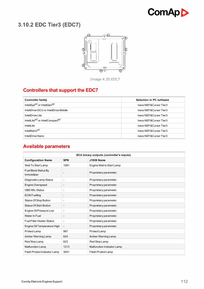
ComApEletronicEnginesSupport 112
3.10.2 EDC Tier3 (EDC7)
Image 4.35 EDC7
Controllers that support the EDC7
Controller family Selection in PC software
InteliSysNTor InteliGenNT Iveco NEF&Cursor Tier3
InteliDrive DCU or InteliDriveMobile Iveco NEF&Cursor Tier3
InteliDrive Lite Iveco NEF&Cursor Tier3
InteliLiteNTor InteliCompactNT Iveco NEF&Cursor Tier3
InteliLite Iveco NEF&Cursor Tier3
InteliNanoNT Iveco NEF&Cursor Tier3
InteliDrive Nano Iveco NEF&Cursor Tier3
Available parametersECU binary outputs (controller's inputs)
Configuration Name SPN J1939 Name
Wait To Start Lamp 1081 EngineWait to Start Lamp
FuelBlockStatusByImmobilizer
- Proprietary parameter.
Diagnostic Lamp Status - Proprietary parameter.
EngineOverspeed - Proprietary parameter.
OBDMIL Status - Proprietary parameter.
ECMFuelling - Proprietary parameter.
StatusOf Stop Button - Proprietary parameter.
StatusOf Start Button - Proprietary parameter.
EngineOil Pressure Low - Proprietary parameter.
Water In Fuel - Proprietary parameter.
Fuel Filter Heater Status - Proprietary parameter.
EngineOil Temperature High - Proprietary parameter.
Protect Lamp 987 Protect Lamp
Amber Warning Lamp 624 Amber Warning Lamp
Red Stop Lamp 623 Red Stop Lamp
Malfunction Lamp 1213 Malfunction Indicator Lamp
Flash Protect Indicator Lamp 3041 Flash Protect Lamp
ComApEletronicEnginesSupport 113
Flash Amber Warning Lamp
3040 Flash Amber Warning Lamp (AWL)Fast Flash Amber WarningLamp
Flash Red Stop Lamp3039 Flash Red Stop Lamp (RSL)
Fast Flash Red Stop Lamp
ECU binary outputs (controller's inputs)
Configuration Name SPN J1939 Name
ECU binary outputs (controller's inputs)
Configuration Name SPN J1939 Name
Engine TorqueMode 899 Engine TorqueMode
Demand Torque 512 Driver'sDemand Engine - Percent Torque
Actual Torque 513 ActualEngine - Percent Torque
Engine speed 190 Engine Speed
Controlling Device Address 1483 Source Addressof Controlling Device for Engine Control
Engine Starter Mode 1675 Engine Starter Mode
Accelerator PedalPosition 91 Accelerator PedalPosition 1
Percent Load 92 Engine Percent Load At Current Speed
Remote Accelerator 974 Remote Accelerator PedalPosition
Nominal Friction - %Torque 514 Nominal Friction - Percent Torque
Desired Operating Speed 515 Engine'sDesired Operating Speed
Operating Speed Asymetry 519 Engine'sDesired Operating Speed AsymmetryAdjustment
Coolant Temp 110 Engine Coolant Temperature
Fuel Temp 174 Engine Fuel Temperature 1
EngineOil Temp 175 EngineOil Temperature 1
TurboOil Temperature 176 Engine Turbocharger Oil Temperature
Intercooler Temperature 52 Engine Intercooler Temperature
BarometricPressure 108 BarometricPressure
Cab Interior Temperature 170 Cab Interior Temperature
Ambient Air Temperature 171 Ambient Air Temperature
Air Inlet Temperature 172 Engine Intake Air Temperature
Trap Inlet Pressure 81 Aftertreatment 1 DieselParticulate Filter Intake Pressure
Boost Pressure 102 Engine IntakeManifold #1 Pressure
IntakeManifold Temp 105 Engine IntakeManifold 1 Temperature
Air Intake Pressure 106 Engine Intake Air Pressure
Air Filter Diff. Pressure 107 Engine Air Filter 1 Differential Pressure
Exhaust GasTemp 173 Engine Exhaust Temperature
Coolant Filter Diff. Pressure 112 Engine Coolant Filter Differential Pressure
FuelDeliveryPressure 94 Engine FuelDeliveryPressure
Extended Crankcase Blow-byPressure
22 Engine Extended Crankcase Blow-byPressure
EngineOil Level 98 EngineOil Level
EngineOil Pressure 100 EngineOil Pressure
Ctankcase Pressure 101 Engine Crankcase Pressure 1
Coolant Pressure 109 Engine Coolant Pressure 1
Engine Coolant Level 111 Engine Coolant Level 1
FuelRate 183 Engine FuelRate
BatteryPotential (Voltage) 158 Keyswitch BatteryPotential
ComApEletronicEnginesSupport 114
Cold Start Status - Proprietary parameter.
EngineOvertemperature - Proprietary parameter.
Engine Degradation Level - Proprietary parameter.
ECMOperationalStatus - Proprietary parameter.
Humidity - Proprietary parameter.
ECU binary outputs (controller's inputs)
Configuration Name SPN J1939 Name
Requested speed 1,2,3,4,5,6 898 Engine Requested Speed/Speed Limit
Supported parameter by the controllers configured byNanoEdit, DriveEdit or LiteEdit PC software:
1 - InteliLiteNT, 2 - InteliLite , 3 - InteliDrive Lite , 4 - InteliCompactNT, 5 - InteliNanoNT, 6 - InteliDrive Nano
Controller’s analog output for speed control configurationRequested speed settings for InteliGenNT or InteliSysNT
Source SpeedReq RPM
Convert NO
LimitsN/A N/A
N/A N/A
Requested speed settings for InteliDrive DCU, InteliDrive Mobile
Source SpeedReq RPM
Convert NO
Limits0.0 % Min eng. speed (800RPM)
100.0 % Max eng. speed (2100RPM)
Recommended wiringFunction ECU A2 89pin connector Controller
CAN H 52 CAN1 (extension modules/J1939) – CANH
CAN COM N/A CAN1 (extensionmodules/J1939) – CAN COM
CAN L 53 CAN1 (extension modules/J1939) – CANL
Battery + (positive) 1, 7, 12, 13 N/A
Battery - (negative) 3, 9, 14, 15 N/A
Key Switch N/A Anybinary output configured asECU PwrRelay
Analog Speed Control N/A SG OUT
Analog Speed Control N/A SGCOM
Formore information about diagnostic connector layout see SAE - J1939 diagnostic connector on page 17.Available list of texts of fault codes see EDC Tier3 (EDC7) on page 273.
3.10.3 ADEM III
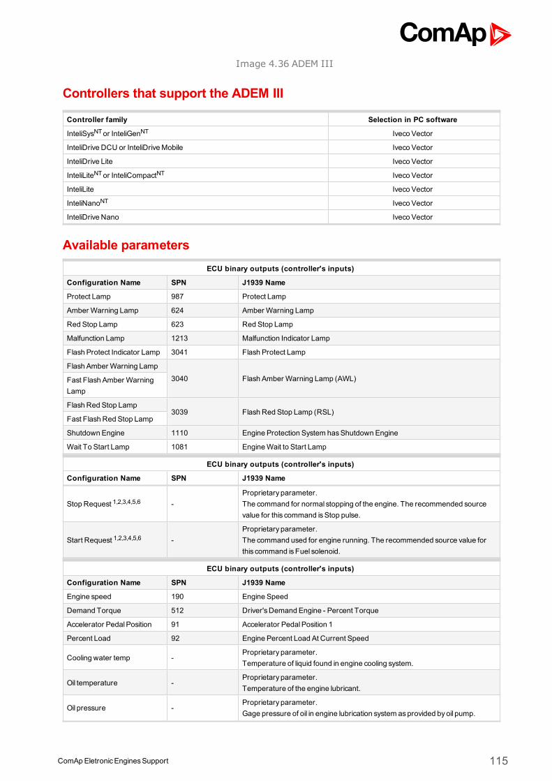
ComApEletronicEnginesSupport 115
Image 4.36 ADEM III
Controllers that support the ADEM III
Controller family Selection in PC software
InteliSysNTor InteliGenNT Iveco Vector
InteliDrive DCU or InteliDriveMobile Iveco Vector
InteliDrive Lite Iveco Vector
InteliLiteNTor InteliCompactNT Iveco Vector
InteliLite Iveco Vector
InteliNanoNT Iveco Vector
InteliDrive Nano Iveco Vector
Available parametersECU binary outputs (controller's inputs)
Configuration Name SPN J1939 Name
Protect Lamp 987 Protect Lamp
Amber Warning Lamp 624 Amber Warning Lamp
Red Stop Lamp 623 Red Stop Lamp
Malfunction Lamp 1213 Malfunction Indicator Lamp
Flash Protect Indicator Lamp 3041 Flash Protect Lamp
Flash Amber Warning Lamp
3040 Flash Amber Warning Lamp (AWL)Fast Flash Amber WarningLamp
Flash Red Stop Lamp3039 Flash Red Stop Lamp (RSL)
Fast Flash Red Stop Lamp
Shutdown Engine 1110 Engine Protection System hasShutdown Engine
Wait To Start Lamp 1081 EngineWait to Start Lamp
ECU binary outputs (controller's inputs)
Configuration Name SPN J1939 Name
Stop Request 1,2,3,4,5,6 -Proprietary parameter.The command for normal stopping of the engine. The recommended sourcevalue for this command isStop pulse.
Start Request 1,2,3,4,5,6 -Proprietary parameter.The command used for engine running. The recommended source value forthis command isFuel solenoid.
ECU binary outputs (controller's inputs)
Configuration Name SPN J1939 Name
Engine speed 190 Engine Speed
Demand Torque 512 Driver'sDemand Engine - Percent Torque
Accelerator PedalPosition 91 Accelerator PedalPosition 1
Percent Load 92 Engine Percent Load At Current Speed
Cooling water temp -Proprietary parameter.Temperature of liquid found in engine cooling system.
Oil temperature -Proprietary parameter.Temperature of the engine lubricant.
Oil pressure -Proprietary parameter.Gage pressure of oil in engine lubrication system asprovided byoil pump.
ComApEletronicEnginesSupport 116
Boost Pressure 102 Engine IntakeManifold #1 Pressure
IntakeManifold Temp 105 Engine IntakeManifold 1 Temperature
FuelRate 183 Engine FuelRate
ECU binary outputs (controller's inputs)
Configuration Name SPN J1939 Name
Requested speed 1,2,3,4,5,6 898 Engine Requested Speed/Speed Limit
Supported parameter by the controllers configured byNanoEdit, DriveEdit or LiteEdit PC software:
1 - InteliLiteNT, 2 - InteliLite , 3 - InteliDrive Lite , 4 - InteliCompactNT, 5 - InteliNanoNT, 6 - InteliDrive Nano
Controller’s analog output for speed control configurationRequested speed settings for InteliGenNT or InteliSysNT
Source SpeedReq RPM
Convert NO
LimitsN/A N/A
N/A N/A
Requested speed settings for InteliDrive DCU, InteliDrive Mobile
Source SpeedReq RPM
Convert NO
Limits0.0 % Min eng. speed (800RPM)
100.0 % Max eng. speed (2100RPM)
Recommended wiringFunction Interface card Controller
CAN H J2 - 1 CAN1 (extension modules/J1939) – CANH
CAN COM N/A CAN1 (extensionmodules/J1939) – CAN COM
CAN L J2 - 2 CAN1 (extension modules/J1939) – CANL
Battery + (positive) 116 N/A
Battery - (negative) 117 N/A
Key Switch J7 - 18,191 Anybinary output configured asECU PwrRelay
Analog Speed Control N/A SG OUT
Analog Speed Control N/A SGCOM
Formore information about diagnostic connector layout see SAE - J1939 diagnostic connector on page 17.Available list of texts of fault codes see ADEM III on page 275.
1Emergency stopmust open this contact. After power on it has to wait for 10 seconds before start the engine - ifECU PwrRelay output is used to close this contact Prestart time has to be set to at least 10 seconds.
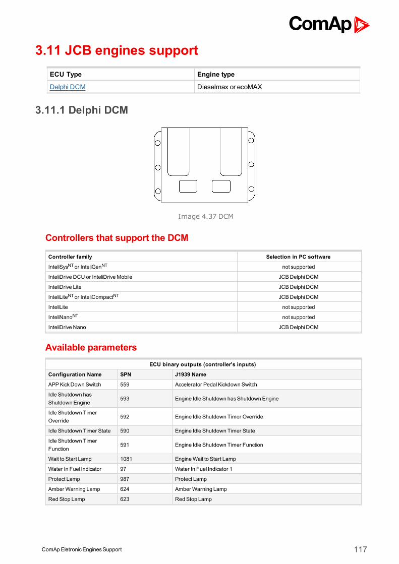
ComApEletronicEnginesSupport 117
3.11 JCB engines supportECU Type Engine type
Delphi DCM Dieselmax or ecoMAX
3.11.1 Delphi DCM
Image 4.37 DCM
Controllers that support the DCM
Controller family Selection in PC software
InteliSysNTor InteliGenNT not supported
InteliDrive DCU or InteliDriveMobile JCBDelphiDCM
InteliDrive Lite JCBDelphiDCM
InteliLiteNTor InteliCompactNT JCBDelphiDCM
InteliLite not supported
InteliNanoNT not supported
InteliDrive Nano JCBDelphiDCM
Available parametersECU binary outputs (controller's inputs)
Configuration Name SPN J1939 Name
APPKickDown Switch 559 Accelerator PedalKickdown Switch
Idle Shutdown hasShutdown Engine
593 Engine Idle Shutdown hasShutdown Engine
Idle Shutdown TimerOverride
592 Engine Idle Shutdown Timer Override
Idle Shutdown Timer State 590 Engine Idle Shutdown Timer State
Idle Shutdown TimerFunction
591 Engine Idle Shutdown Timer Function
Wait to Start Lamp 1081 EngineWait to Start Lamp
Water In Fuel Indicator 97 Water In Fuel Indicator 1
Protect Lamp 987 Protect Lamp
Amber Warning Lamp 624 Amber Warning Lamp
Red Stop Lamp 623 Red Stop Lamp
ComApEletronicEnginesSupport 118
Malfunction Lamp 1213 Malfunction Indicator Lamp
Flash Protect IndicatorLamp
3041 Flash Protect Lamp
Flash Amber WarningLamp
3040 Flash Amber Warning Lamp (AWL)Fast Flash Amber WarningLamp
Flash Red Stop Lamp3039 Flash Red Stop Lamp (RSL)
Fast Flash Red Stop Lamp
Bank1 Intake Dew Point 3237 Aftertreatment 1 Intake Dew Point
Bank1 Exhaust Dew Point 3238 Aftertreatment 1 Exhaust Dew Point
Bank2 Intake Dew Point 3239 Aftertreatment 2 Intake Dew Point
Bank2 Exhaust Dew Point 3240 Aftertreatment 2 Exhaust Dew Point
ECU binary outputs (controller's inputs)
Configuration Name SPN J1939 Name
DPF Regeneration InhibitSwitch 1,3,4
3695 Aftertreatment Regeneration Inhibit Switch
DPF Regeneration ForceSwitch 1,3,4
3696 Aftertreatment Regeneration Force Switch
ECU binary outputs (controller's inputs)
Configuration Name SPN J1939 Name
Engine TorqueMode 558 Accelerator Pedal 1 Low Idle Switch
Engine speed 190 Engine Speed
Actual Torque 513 ActualEngine - Percent Torque
Demand Torque 512 Driver'sDemand Engine - Percent Torque
Engine Demand Torque 5398 Estimated Pumping - Percent Torque
Coolant Temp 110 Engine Coolant Temperature
Fuel Temp 174 Engine Fuel Temperature 1
EngineOil Temp 175 EngineOil Temperature 1
T-ECU 1136 Engine ECU Temperature
Boost Pressure 102 Engine IntakeManifold #1 Pressure
IntakeManifold Temp 105 Engine IntakeManifold 1 Temperature
Accelerator PedalPosition 91 Accelerator PedalPosition 1
Percent Load 92 Engine Percent Load At Current Speed
Remote Accelerator 974 Remote Accelerator PedalPosition
FuelRate 183 Engine FuelRate
BatteryPotential (Voltage) 158 Keyswitch BatteryPotential
EngineOil Level 98 EngineOil Level
EngineOil Pressure 100 EngineOil Pressure
Estimated Percent FanSpeed
975 Engine Fan 1 Estimated Percent Speed
Fan Drive State 977 Fan Drive State
Intake NOx 3216 Aftertreatment 1 Selective CatalyticReduction Intake NOx
AT1 IntakeO2 3217 Aftertreatment 1 Intake Percent O2
Aftertreat1 ExhGasTemp 1 3241 Aftertreatment 1 Exhaust Temperature 1
Outlet NOx 3226 Aftertreatment 1 Outlet NOx
AT1Outlet O2 3227 Aftertreatment 1 Outlet Percent O2
DEF Tank1 Level 1761 Aftertreatment 1 DieselExhaust Fluid TankLevel
ComApEletronicEnginesSupport 119
DieselExhaust Fluid Tank1Temperature
3031 Aftertreatment 1 DieselExhaust Fluid TankTemperature
Aftertreatment Lamp Status 517640 Manufacturer Assignable SPN
Inducement Level 517641 Manufacturer Assignable SPN
Refresh StatusByte 517649 Manufacturer Assignable SPN
SCRMonitor 517650 Manufacturer Assignable SPN
SuccessfulRunningRefreshes
517651 Manufacturer Assignable SPN
SuccessfulStationaryRefreshes
517652 Manufacturer Assignable SPN
ECU binary outputs (controller's inputs)
Configuration Name SPN J1939 Name
Requested speed 1,3,4,6 898 Engine Requested Speed/Speed Limit
Fuel Level 96 Fuel Level 1
Supported parameter by the controllers configured byNanoEdit, DriveEdit or LiteEdit PC software:
1 - InteliLiteNT, 2 - InteliLite , 3 - InteliDrive Lite , 4 - InteliCompactNT, 5 - InteliNanoNT, 6 - InteliDrive Nano
Controller’s analog output for speed control configurationRequested speed settings for InteliGenNT or InteliSysNT
Source SpeedReq RPM
Convert NO
LimitsN/A N/A
N/A N/A
Requested speed settings for InteliDrive DCU, InteliDrive Mobile
Source SpeedReq RPM
Convert NO
Limits0.0 % Min eng. speed (800RPM)
100.0 % Max eng. speed (2100RPM)
Recommended wiringFunction ECU X2 62pin connector Controller
CAN H 27 CAN1 (extension modules/J1939) – CANH
CAN COM 19 CAN1 (extensionmodules/J1939) – CAN COM
CAN L 23 CAN1 (extension modules/J1939) – CANL
Battery + (positive) 57,60,53,49 N/A
Battery - (negative) 58,59,61,62 N/A
Key Switch N/A Anybinary output configured asECU PwrRelay
Analog Speed Control N/A SG OUT
Analog Speed Control N/A SGCOM
Formore information about diagnostic connector layout see SAE - J1939 diagnostic connector on page 17.Available list of texts of fault codes see Delphi DCM on page 276.
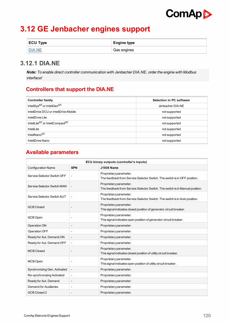
ComApEletronicEnginesSupport 120
3.12 GE Jenbacher engines supportECU Type Engine type
DIA.NE Gas engines
3.12.1 DIA.NENote: To enable direct controller communication with Jenbacher DIA.NE, order the engine with Modbusinterface!
Controllers that support the DIA.NE
Controller family Selection in PC software
InteliSysNTor InteliGenNT Jenbacher DIA.NE
InteliDrive DCU or InteliDriveMobile not supported
InteliDrive Lite not supported
InteliLiteNTor InteliCompactNT not supported
InteliLite not supported
InteliNanoNT not supported
InteliDrive Nano not supported
Available parametersECU binary outputs (controller's inputs)
Configuration Name SPN J1939 Name
Service Selector Switch OFF -Proprietary parameter.The feedback from Service Selector Switch. The switch is in OFF position.
Service Selector SwitchMAN -Proprietary parameter.The feedback from Service Selector Switch. The switch is in Manual position.
Service Selector Switch AUT -Proprietary parameter.The feedback from Service Selector Switch. The switch is in Auto position.
GCBClosed -Proprietary parameter.This signal indicates closed position of generator circuit breaker.
GCBOpen -Proprietary parameter.This signal indicatesopen position of generator circuit breaker.
Operation ON - Proprietary parameter.
Operation OFF - Proprietary parameter.
Ready for Aut. DemandON - Proprietary parameter.
Ready for Aut. DemandOFF - Proprietary parameter.
MCBClosed -Proprietary parameter.This signal indicates closed position of utility circuit breaker.
MCBOpen -Proprietary parameter.This signal indicatesopen position of utility circuit breaker.
Synchronizing Gen. Activated - Proprietary parameter.
Re-synchronizing Activated - Proprietary parameter.
Ready for Aut. Demand - Proprietary parameter.
Demand for Auxiliaries - Proprietary parameter.
GCBClosed 2 - Proprietary parameter.
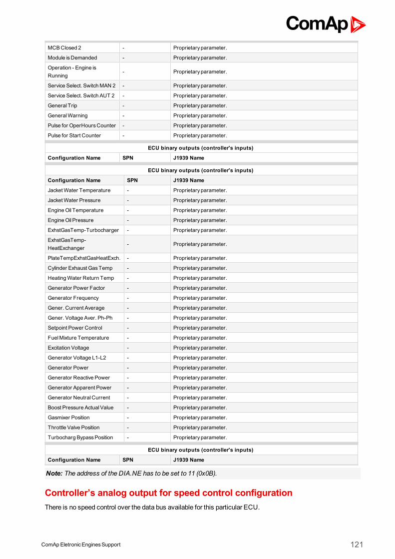
ComApEletronicEnginesSupport 121
MCBClosed 2 - Proprietary parameter.
Module isDemanded - Proprietary parameter.
Operation - Engine isRunning
- Proprietary parameter.
Service Select. SwitchMAN 2 - Proprietary parameter.
Service Select. Switch AUT 2 - Proprietary parameter.
General Trip - Proprietary parameter.
GeneralWarning - Proprietary parameter.
Pulse for OperHoursCounter - Proprietary parameter.
Pulse for Start Counter - Proprietary parameter.
ECU binary outputs (controller's inputs)
Configuration Name SPN J1939 Name
ECU binary outputs (controller's inputs)
Configuration Name SPN J1939 Name
JacketWater Temperature - Proprietary parameter.
JacketWater Pressure - Proprietary parameter.
EngineOil Temperature - Proprietary parameter.
EngineOil Pressure - Proprietary parameter.
ExhstGasTemp-Turbocharger - Proprietary parameter.
ExhstGasTemp-HeatExchanger
- Proprietary parameter.
PlateTempExhstGasHeatExch. - Proprietary parameter.
Cylinder Exhaust GasTemp - Proprietary parameter.
HeatingWater Return Temp - Proprietary parameter.
Generator Power Factor - Proprietary parameter.
Generator Frequency - Proprietary parameter.
Gener. Current Average - Proprietary parameter.
Gener. Voltage Aver. Ph-Ph - Proprietary parameter.
Setpoint Power Control - Proprietary parameter.
FuelMixture Temperature - Proprietary parameter.
Excitation Voltage - Proprietary parameter.
Generator Voltage L1-L2 - Proprietary parameter.
Generator Power - Proprietary parameter.
Generator Reactive Power - Proprietary parameter.
Generator Apparent Power - Proprietary parameter.
Generator NeutralCurrent - Proprietary parameter.
Boost Pressure ActualValue - Proprietary parameter.
Gasmixer Position - Proprietary parameter.
Throttle Valve Position - Proprietary parameter.
Turbocharg BypassPosition - Proprietary parameter.
ECU binary outputs (controller's inputs)
Configuration Name SPN J1939 Name
Note: The address of the DIA.NE has to be set to 11 (0x0B).
Controller’s analog output for speed control configurationThere is no speed control over the data bus available for this particular ECU.
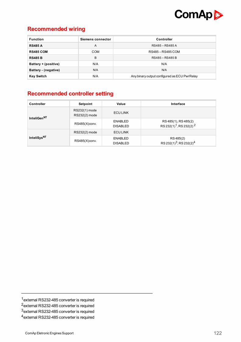
ComApEletronicEnginesSupport 122
Recommended wiringFunction Siemens connector Controller
RS485 A A RS485 – RS485 A
RS485 COM COM RS485 – RS485COM
RS485 B B RS485 – RS485 B
Battery + (positive) N/A N/A
Battery - (negative) N/A N/A
Key Switch N/A Anybinary output configured asECU PwrRelay
Recommended controller settingController Setpoint Value Interface
InteliGenNT
RS232(1) modeRS232(2) mode
ECU LINK
RS485(X)conv.ENABLEDDISABLED
RS485(1), RS 485(2)RS 232(1)1, RS 232(2) 2
InteliSysNTRS232(2) mode ECU LINK
RS485(X)conv.ENABLEDDISABLED
RS485(2)RS 232(1)3, RS 232(2)4
1external RS232-485 converter is required2external RS232-485 converter is required3external RS232-485 converter is required4external RS232-485 converter is required
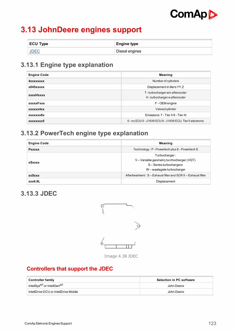
ComApEletronicEnginesSupport 123
3.13 JohnDeere engines supportECU Type Engine type
JDEC Diesel engines
3.13.1 Engine type explanationEngine Code Meaning
4xxxxxxxx Number of cylinders
x045xxxxx Displacement in litersYY.Z
xxxxHxxxxT - turbochargerw/o aftercoolerH - turbochargerw aftercooler
xxxxxFxxx F - OEM engine
xxxxxx4xx Valves/cylinder
xxxxxxx8x Emissions: 7 - Tier II 8 - Tier III
xxxxxxxx5 0 - no ECU5 - J1939 ECU9 - J1939 ECU, Tier II electronic
3.13.2 PowerTech engine type explanationEngine Code Meaning
Pxxxxx Technology : P - Powertech plus E -Powertech E
xSxxxx
Turbocharger :V – Variable geometry turchocharger (VGT)
S – Series turbochargersW–wastegate turbocharger
xxSxxx Aftertreatment : S – Exhaust filter and SCRX – Exhaust filter
xxx6.8L Displacement
3.13.3 JDEC
Image 4.38 JDEC
Controllers that support the JDEC
Controller family Selection in PC software
InteliSysNTor InteliGenNT John Deere
InteliDrive DCU or InteliDriveMobile John Deere
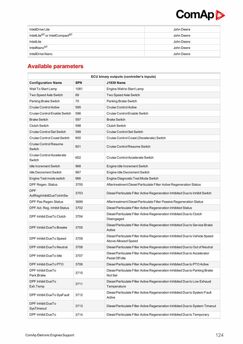
ComApEletronicEnginesSupport 124
InteliDrive Lite John Deere
InteliLiteNTor InteliCompactNT John Deere
InteliLite John Deere
InteliNanoNT John Deere
InteliDrive Nano John Deere
Available parametersECU binary outputs (controller's inputs)
Configuration Name SPN J1939 Name
Wait To Start Lamp 1081 EngineWait to Start Lamp
Two Speed Axle Switch 69 Two Speed Axle Switch
Parking Brake Switch 70 Parking Brake Switch
Cruise Control Active 595 Cruise Control Active
Cruise Control Enable Switch 596 Cruise Control Enable Switch
Brake Switch 597 Brake Switch
Clutch Switch 598 Clutch Switch
Cruise Control Set Switch 599 Cruise Control Set Switch
Cruise ControlCoast Switch 600 Cruise ControlCoast (Decelerate) Switch
Cruise ControlResumeSwitch
601 Cruise ControlResumeSwitch
Cruise Control AccelerateSwitch
602 Cruise Control Accelerate Switch
Idle Increment Switch 968 Engine Idle Increment Switch
Idle Decrement Switch 967 Engine Idle Decrement Switch
Engine Test mode switch 966 Engine Diagnostic Test Mode Switch
DPF Regen. Status 3700 Aftertreatment DieselParticulate Filter Active Regeneration Status
DPFActRegInhibitDueToInhSw
3703 DieselParticulate Filter Active Regeneration Inhibited Due to Inhibit Switch
DPF Pas.Regen.Status 3699 Aftertreatment DieselParticulate Filter Passive Regeneration Status
DPF Act. Reg. Inhibit Status 3702 DieselParticulate Filter Active Regeneration Inhibited Status
DPF Inhibit DueToClutch 3704DieselParticulate Filter Active Regeneration Inhibited Due to ClutchDisengaged
DPF Inhibit DueTo Breake 3705DieselParticulate Filter Active Regeneration Inhibited Due to Service BrakeActive
DPF Inhibit DueTo Speed 3709DieselParticulate Filter Active Regeneration Inhibited Due to Vehicle SpeedAbove Allowed Speed
DPF Inhibit DueToNeutral 3708 DieselParticulate Filter Active Regeneration Inhibited Due to Out of Neutral
DPF Inhibit DueTo Idle 3707DieselParticulate Filter Active Regeneration Inhibited Due to AcceleratorPedalOff Idle
DPF Inhibit DueTo PTO 3706 DieselParticulate Filter Active Regeneration Inhibited Due to PTOActive
DPF Inhibit DueToPark.Brake
3710DieselParticulate Filter Active Regeneration Inhibited Due to Parking BrakeNot Set
DPF Inhibit DueToExh.Temp
3711DieselParticulate Filter Active Regeneration Inhibited Due to Low ExhaustTemperature
DPF Inhibit DueTo SysFault 3712DieselParticulate Filter Active Regeneration Inhibited Due to System FaultActive
DPF Inhibit DueToSysTimeout
3713 DieselParticulate Filter Active Regeneration Inhibited Due to System Timeout
DPF Inhibit DueTo 3714 DieselParticulate Filter Active Regeneration Inhibited Due to Temporary
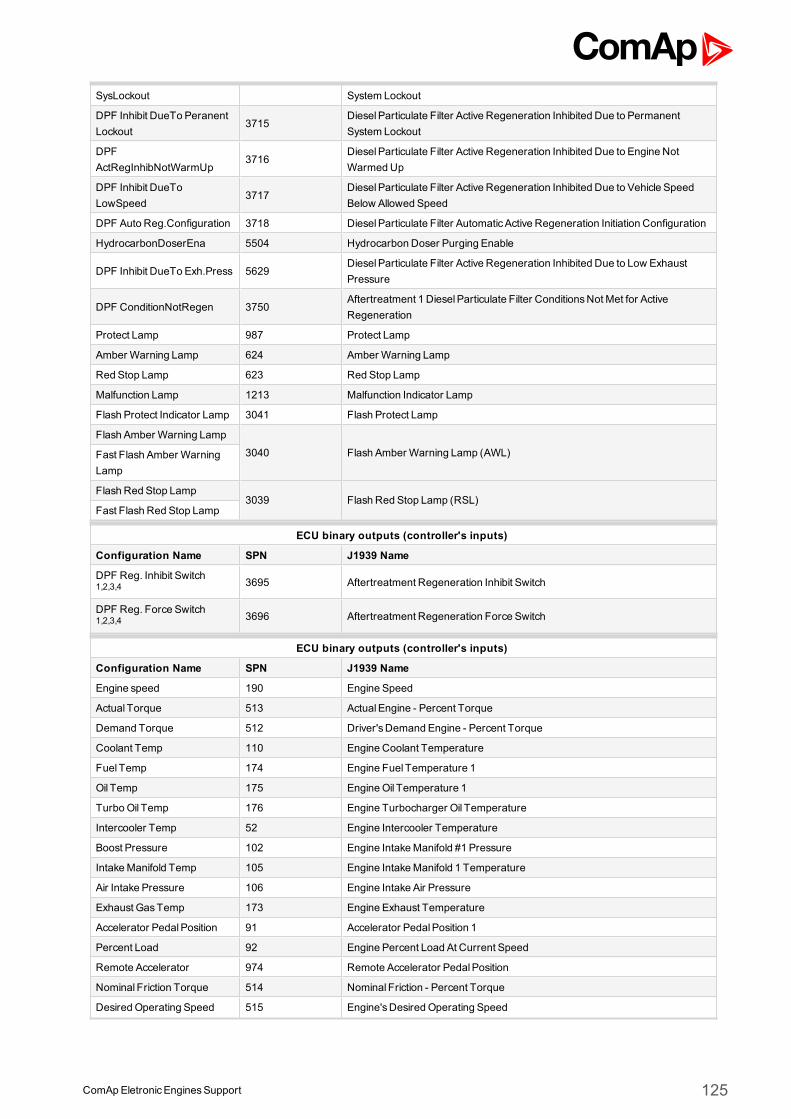
ComApEletronicEnginesSupport 125
SysLockout System Lockout
DPF Inhibit DueTo PeranentLockout
3715DieselParticulate Filter Active Regeneration Inhibited Due to PermanentSystem Lockout
DPFActRegInhibNotWarmUp
3716DieselParticulate Filter Active Regeneration Inhibited Due to Engine NotWarmedUp
DPF Inhibit DueToLowSpeed
3717DieselParticulate Filter Active Regeneration Inhibited Due to Vehicle SpeedBelow Allowed Speed
DPF Auto Reg.Configuration 3718 DieselParticulate Filter AutomaticActive Regeneration Initiation Configuration
HydrocarbonDoserEna 5504 Hydrocarbon Doser Purging Enable
DPF Inhibit DueTo Exh.Press 5629DieselParticulate Filter Active Regeneration Inhibited Due to Low ExhaustPressure
DPF ConditionNotRegen 3750Aftertreatment 1 DieselParticulate Filter ConditionsNot Met for ActiveRegeneration
Protect Lamp 987 Protect Lamp
Amber Warning Lamp 624 Amber Warning Lamp
Red Stop Lamp 623 Red Stop Lamp
Malfunction Lamp 1213 Malfunction Indicator Lamp
Flash Protect Indicator Lamp 3041 Flash Protect Lamp
Flash Amber Warning Lamp
3040 Flash Amber Warning Lamp (AWL)Fast Flash Amber WarningLamp
Flash Red Stop Lamp3039 Flash Red Stop Lamp (RSL)
Fast Flash Red Stop Lamp
ECU binary outputs (controller's inputs)
Configuration Name SPN J1939 Name
DPF Reg. Inhibit Switch1,2,3,4 3695 Aftertreatment Regeneration Inhibit Switch
DPF Reg. Force Switch1,2,3,4 3696 Aftertreatment Regeneration Force Switch
ECU binary outputs (controller's inputs)
Configuration Name SPN J1939 Name
Engine speed 190 Engine Speed
Actual Torque 513 ActualEngine - Percent Torque
Demand Torque 512 Driver'sDemand Engine - Percent Torque
Coolant Temp 110 Engine Coolant Temperature
Fuel Temp 174 Engine Fuel Temperature 1
Oil Temp 175 EngineOil Temperature 1
TurboOil Temp 176 Engine Turbocharger Oil Temperature
Intercooler Temp 52 Engine Intercooler Temperature
Boost Pressure 102 Engine IntakeManifold #1 Pressure
IntakeManifold Temp 105 Engine IntakeManifold 1 Temperature
Air Intake Pressure 106 Engine Intake Air Pressure
Exhaust GasTemp 173 Engine Exhaust Temperature
Accelerator PedalPosition 91 Accelerator PedalPosition 1
Percent Load 92 Engine Percent Load At Current Speed
Remote Accelerator 974 Remote Accelerator PedalPosition
Nominal Friction Torque 514 Nominal Friction - Percent Torque
Desired Operating Speed 515 Engine'sDesired Operating Speed
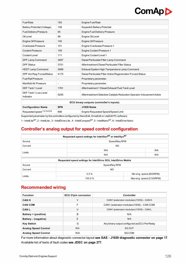
ComApEletronicEnginesSupport 126
FuelRate 183 Engine FuelRate
BatteryPotential (Voltage) 158 Keyswitch BatteryPotential
FuelDeliveryPressure 94 Engine FuelDeliveryPressure
Oil Level 98 EngineOil Level
EngineOil Pressure 100 EngineOil Pressure
Crankcase Pressure 101 Engine Crankcase Pressure 1
Coolant Pressure 109 Engine Coolant Pressure 1
Coolant Level 111 Engine Coolant Level 1
DPF LampCommand 3697 DieselParticulate Filter LampCommand
DPF Status 3701 Aftertreatment DieselParticulate Filter Status
HEST LampCommand 3698 Exhaust SystemHigh Temperature LampCommand
DPF Act.Reg.ForcedStatus 4175 DieselParticulate Filter Active Regeneration Forced Status
FuelRail Pressure - Proprietary parameter.
Manifold Air Pressure - Proprietary parameter.
DEF Tank1 Level 1761 Aftertreatment 1 DieselExhaust Fluid TankLevel
DEF Tank1 Low LevelIndicator
5245 Aftertreatment Selective CatalyticReduction Operator Inducement Active
ECU binary outputs (controller's inputs)
Configuration Name SPN J1939 Name
Requested speed 1,2,3,4,5,6 898 Engine Requested Speed/Speed Limit
Supported parameter by the controllers configured byNanoEdit, DriveEdit or LiteEdit PC software:
1 - InteliLiteNT, 2 - InteliLite , 3 - InteliDrive Lite , 4 - InteliCompactNT, 5 - InteliNanoNT, 6 - InteliDrive Nano
Controller’s analog output for speed control configurationRequested speed settings for InteliGenNT or InteliSysNT
Source SpeedReq RPM
Convert NO
LimitsN/A N/A
N/A N/A
Requested speed settings for InteliDrive DCU, InteliDrive Mobile
Source SpeedReq RPM
Convert NO
Limits0.0 % Min eng. speed (800RPM)
100.0 % Max eng. speed (2100RPM)
Recommended wiringFunction ECU 21pin connector Controller
CAN H V CAN1 (extension modules/J1939) – CANH
CAN COM F CAN1 (extensionmodules/J1939) – CAN COM
CAN L U CAN1 (extension modules/J1939) – CANL
Battery + (positive) B N/A
Battery - (negative) E N/A
Key Switch G Anybinary output configured asECU PwrRelay
Analog Speed Control N/A SG OUT
Analog Speed Control N/A SGCOM
Formore information about diagnostic connector layout see SAE - J1939 diagnostic connector on page 17.Available list of texts of fault codes see JDEC on page 277.
ComApEletronicEnginesSupport 127
Note:Important JDEC settings for speed control via CAN are:Torque speed control - Enable TSC1 Source 1; Source Address 1 set to 3Governor droop – Set RPM of droop to e.g. 36 (it will enable controller to vary engine speed its nominal speed)Throttle – Disable all throttles
ComApEletronicEnginesSupport 128
3.14 Kubota engines supportECU Type Engine type
ECM diesel engines
3.14.1 ECM
Image 4.39 ECM
Controllers that support the ECM
Controller family Selection in PC software
InteliSysNTor InteliGenNT Kubota
InteliDrive DCU or InteliDriveMobile Kubota
InteliDrive Lite Kubota
InteliLiteNTor InteliCompactNT Kubota
InteliLite Kubota
InteliNanoNT Kubota
InteliDrive Nano Kubota
Available parametersECU binary outputs (controller's inputs)
Configuration Name SPN J1939 Name
Wait To Start Lamp 1081 EngineWait to Start Lamp
Engine Protection SystemhasShutdown Engine
1110 Engine Protection System hasShutdown Engine
Engine Emergency(Immediate) ShutdownIndication
3607 Engine Emergency (Immediate) Shutdown Indication
DPF Active RegenerationStatus
3700 Aftertreatment DieselParticulate Filter Active Regeneration Status
DPF Active RegenerationInhibit State
3702 DieselParticulate Filter Active Regeneration Inhibited Status
DPF Active RegenerationInhibit Due To Inhibit Switch
3703 DieselParticulate Filter Active Regeneration Inhibited Due to Inhibit Switch
DPF Active RegenerationInhibit Due To AcceleratorPedalOff Idle
3707DieselParticulate Filter Active Regeneration Inhibited Due to AcceleratorPedalOff Idle
ComApEletronicEnginesSupport 129
DPF Active RenegerationInhibit Due ToOut Of Neutral
3708 DieselParticulate Filter Active Regeneration Inhibited Due to Out of Neutral
DPF Active RegenerationInhibit Due To Parking BreakNot Set
3710DieselParticulate Filter Active Regeneration Inhibited Due to Parking BrakeNot Set
DPF Active Regenerationinhibit Due To Low ExhaustGasTemp
3711DieselParticulate Filter Active Regeneration Inhibited Due to Low ExhaustTemperature
DPF Active RegenerationInhibit Due To System FaultActive
3712DieselParticulate Filter Active Regeneration Inhibited Due to System FaultActive
DPF Active RegenerationInhibit Due To SystemTimeout
3713 DieselParticulate Filter Active Regeneration Inhibited Due to System Timeout
DPF Active RegenerationInhibit Due To PermanentSystem Lockout
3715DieselParticulate Filter Active Regeneration Inhibited Due to PermanentSystem Lockout
DPF Active RegenerationInhibit Due To Engine NotWarmedUp
3716DieselParticulate Filter Active Regeneration Inhibited Due to Engine NotWarmedUp
Protect Lamp 987 Protect Lamp
Amber Warning Lamp 624 Amber Warning Lamp
Red Stop Lamp 623 Red Stop Lamp
Malfunction Lamp 1213 Malfunction Indicator Lamp
Flash Protect Indicator Lamp 3041 Flash Protect Lamp
Flash Amber Warning Lamp
3040 Flash Amber Warning Lamp (AWL)Fast Flash Amber WarningLamp
Flash Red Stop Lamp3039 Flash Red Stop Lamp (RSL)
Fast Flash Red Stop Lamp
ECU binary outputs (controller's inputs)
Configuration Name SPN J1939 Name
DPF Reg. Inhibit Switch1,2,3,4 3695 Aftertreatment Regeneration Inhibit Switch
DPF Regeneration ForceSwitch 1,2,3,4
3696 Aftertreatment Regeneration Force Switch
ECU binary outputs (controller's inputs)
Configuration Name SPN J1939 Name
Throttle position 51 Engine Throttle Valve 1 Position 1
Accelerator PedalPosition 91 Accelerator PedalPosition 1
Percent Load 92 Engine Percent Load At Current Speed
EngineOil Pressure 100 EngineOil Pressure
Boost Pressure 102 Engine IntakeManifold #1 Pressure
IntakeManifold Temp 105 Engine IntakeManifold 1 Temperature
BarometricPressure 108 BarometricPressure
Coolant Temp 110 Engine Coolant Temperature
Inlet Air MassFlow Rate 132 Engine Intake Air MassFlow Rate
Injector Metering RailPressure
157 Engine Injector Metering Rail 1 Pressure
BatteryPotential (Voltage) 168 BatteryPotential / Power Input 1
ComApEletronicEnginesSupport 130
Ambient Air Temperature 171 Ambient Air Temperature
Air Inlet Temperature 172 Engine Intake Air Temperature
Fuel Temperature 174 Engine Fuel Temperature 1
FuelRate 183 Engine FuelRate
Engine speed 190 Engine Speed
Actual Torque 513 ActualEngine - Percent Torque
Engine Starter Mode 1675 Engine Starter Mode
Aftertreatment 1 DieselParticulate Filter IntakeGasTemperature
3242 Aftertreatment 1 DieselParticulate Filter Intake Temperature
Aftertreatment 1 DieselParticulate Filter Outlet GasTemperature
3246 Aftertreatment 1 DieselParticulate Filter Outlet Temperature
Aftertreatment 1 DieselParticulate Filter DifferentialPressure
3251 Aftertreatment 1 DieselParticulate Filter Differential Pressure
DPF LampCommand 3697 DieselParticulate Filter LampCommand
HEST LampCommand 3698 Exhaust SystemHigh Temperature LampCommand
DPF Status 3701 Aftertreatment DieselParticulate Filter Status
Aftertreatment 1 DieselOxidation Catalyst IntakeGasTemperature
4765 Aftertreatment 1 DieselOxidation Catalyst Intake Temperature
Soot Mass 4781 Aftertreatment 1 DieselParticulate Filter Soot Mass
ECU binary outputs (controller's inputs)
Configuration Name SPN J1939 Name
Requested speed 1,2,3,4,5,6 898 Engine Requested Speed/Speed Limit
Supported parameter by the controllers configured byNanoEdit, DriveEdit or LiteEdit PC software:
1 - InteliLiteNT, 2 - InteliLite , 3 - InteliDrive Lite , 4 - InteliCompactNT, 5 - InteliNanoNT, 6 - InteliDrive Nano
Controller’s analog output for speed control configurationRequested speed settings for InteliGenNT or InteliSysNT
Source SpeedReq RPM
Convert NO
LimitsN/A N/A
N/A N/A
Requested speed settings for InteliDrive DCU, InteliDrive Mobile
Source SpeedReq RPM
Convert NO
Limits0.0 % Min eng. speed (800RPM)
100.0 % Max eng. speed (2100RPM)
Recommended wiringFunction ECU connector Controller
CAN H CAN1 (extension modules/J1939) – CANH
CAN COM CAN1 (extensionmodules/J1939) – CAN COM
CAN L CAN1 (extension modules/J1939) – CANL
Battery + (positive) N/A
Battery - (negative) N/A
ComApEletronicEnginesSupport 131
Key Switch Anybinary output configured asECU PwrRelay
Analog Speed Control SGOUT
Analog Speed Control SGCOM
Formore information about diagnostic connector layout see SAE - J1939 diagnostic connector on page 17.Available list of texts of fault codes see ECM on page 278.
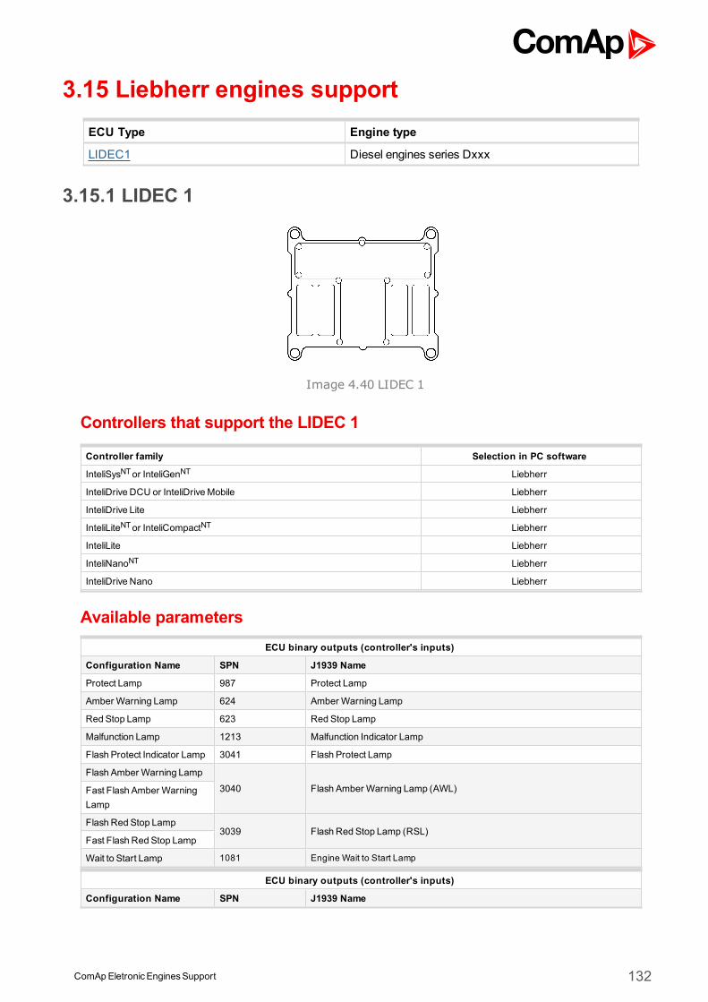
ComApEletronicEnginesSupport 132
3.15 Liebherr engines supportECU Type Engine type
LIDEC1 Diesel engines series Dxxx
3.15.1 LIDEC 1
Image 4.40 LIDEC 1
Controllers that support the LIDEC 1
Controller family Selection in PC software
InteliSysNTor InteliGenNT Liebherr
InteliDrive DCU or InteliDriveMobile Liebherr
InteliDrive Lite Liebherr
InteliLiteNTor InteliCompactNT Liebherr
InteliLite Liebherr
InteliNanoNT Liebherr
InteliDrive Nano Liebherr
Available parametersECU binary outputs (controller's inputs)
Configuration Name SPN J1939 Name
Protect Lamp 987 Protect Lamp
Amber Warning Lamp 624 Amber Warning Lamp
Red Stop Lamp 623 Red Stop Lamp
Malfunction Lamp 1213 Malfunction Indicator Lamp
Flash Protect Indicator Lamp 3041 Flash Protect Lamp
Flash Amber Warning Lamp
3040 Flash Amber Warning Lamp (AWL)Fast Flash Amber WarningLamp
Flash Red Stop Lamp3039 Flash Red Stop Lamp (RSL)
Fast Flash Red Stop Lamp
Wait to Start Lamp 1081 Engine Wait to Start Lamp
ECU binary outputs (controller's inputs)
Configuration Name SPN J1939 Name
ComApEletronicEnginesSupport 133
ECU binary outputs (controller's inputs)
Configuration Name SPN J1939 Name
Accelerator PedalPosition 91 Accelerator PedalPosition 1
Percent Load 92 Engine Percent Load At Current Speed
Engine Speed 190 Engine Speed
Torque 513 ActualEngine - Percent Torque
ECU Temperature 1136 Engine ECU Temperature
Injector Metering Rail 1Pressure
157 Engine Injector Metering Rail 1 Pressure
Injector Metering Rail 2Pressure
1349 Engine Injector Metering Rail 2 Pressure
Desired Operating Speed 515 Engine'sDesired Operating Speed
Intercooler Temp 52 Engine Intercooler Temperature
Coolant Temperature 110 Engine Coolant Temperature
Fuel Temperature 174 Engine Fuel Temperature 1
FuelDeliveryPressure 94 Engine FuelDeliveryPressure
Oil Pressure 100 EngineOil Pressure
Coolant Level 111 Engine Coolant Level 1
FuelRate 183 Engine FuelRate
BarometricPressure 108 BarometricPressure
IntakeManifold Temp 105 Engine IntakeManifold 1 Temperature
Air Inlet Pressure 106 Engine Intake Air Pressure
BatteryPotential (Voltage) 158 Keyswitch BatteryPotential
ECU binary outputs (controller's inputs)
Configuration Name SPN J1939 Name
Requested speed 1,2,3,4,5,6 898 Engine Requested Speed/Speed Limit
Supported parameter by the controllers configured byNanoEdit, DriveEdit or LiteEdit PC software:
1 - InteliLiteNT, 2 - InteliLite , 3 - InteliDrive Lite , 4 - InteliCompactNT, 5 - InteliNanoNT, 6 - InteliDrive Nano
Controller’s analog output for speed control configurationRequested speed settings for InteliGenNT or InteliSysNT
Source SpeedReq RPM
Convert NO
LimitsN/A N/A
N/A N/A
Requested speed settings for InteliDrive DCU, InteliDrive Mobile
Source SpeedReq RPM
Convert NO
Limits0.0 % Min eng. speed (800RPM)
100.0 % Max eng. speed (2100RPM)
Recommended wiringFunction 9pin diagnostic connector Controller
CAN H C CAN1 (extensionmodules/J1939) – CAN H
CAN COM E CAN1 (extensionmodules/J1939) – CAN COM
CAN L D CAN1 (extensionmodules/J1939) – CAN L
ComApEletronicEnginesSupport 134
Battery + (positive) B N/A
Battery - (negative) A N/A
Key Switch N/A Anybinary output configured asECU PwrRelay
Analog Speed Control N/A SGOUT
Analog Speed Control N/A SGCOM
Formore information about diagnostic connector layout see SAE - J1939 diagnostic connector on page 17.Available list of texts of fault codes see LIDEC1 on page 279.
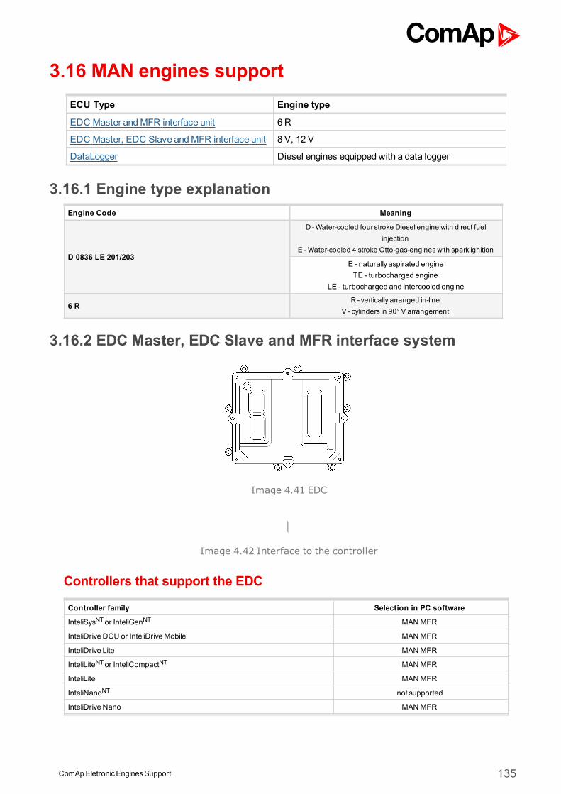
ComApEletronicEnginesSupport 135
3.16 MAN engines supportECU Type Engine type
EDC Master andMFR interface unit 6 R
EDC Master, EDC Slave andMFR interface unit 8 V, 12 V
DataLogger Diesel engines equipped with a data logger
3.16.1 Engine type explanationEngine Code Meaning
D 0836 LE 201/203
D -Water-cooled four stroke Diesel engine with direct fuelinjection
E -Water-cooled 4 stroke Otto-gas-engines with spark ignition
E - naturally aspirated engineTE - turbocharged engine
LE - turbocharged and intercooled engine
6 RR - vertically arranged in-line
V - cylinders in 90° V arrangement
3.16.2 EDC Master, EDC Slave and MFR interface system
Image 4.41 EDC
Image 4.42 Interface to the controller
Controllers that support the EDC
Controller family Selection in PC software
InteliSysNTor InteliGenNT MANMFR
InteliDrive DCU or InteliDriveMobile MANMFR
InteliDrive Lite MANMFR
InteliLiteNTor InteliCompactNT MANMFR
InteliLite MAN MFR
InteliNanoNT not supported
InteliDrive Nano MANMFR
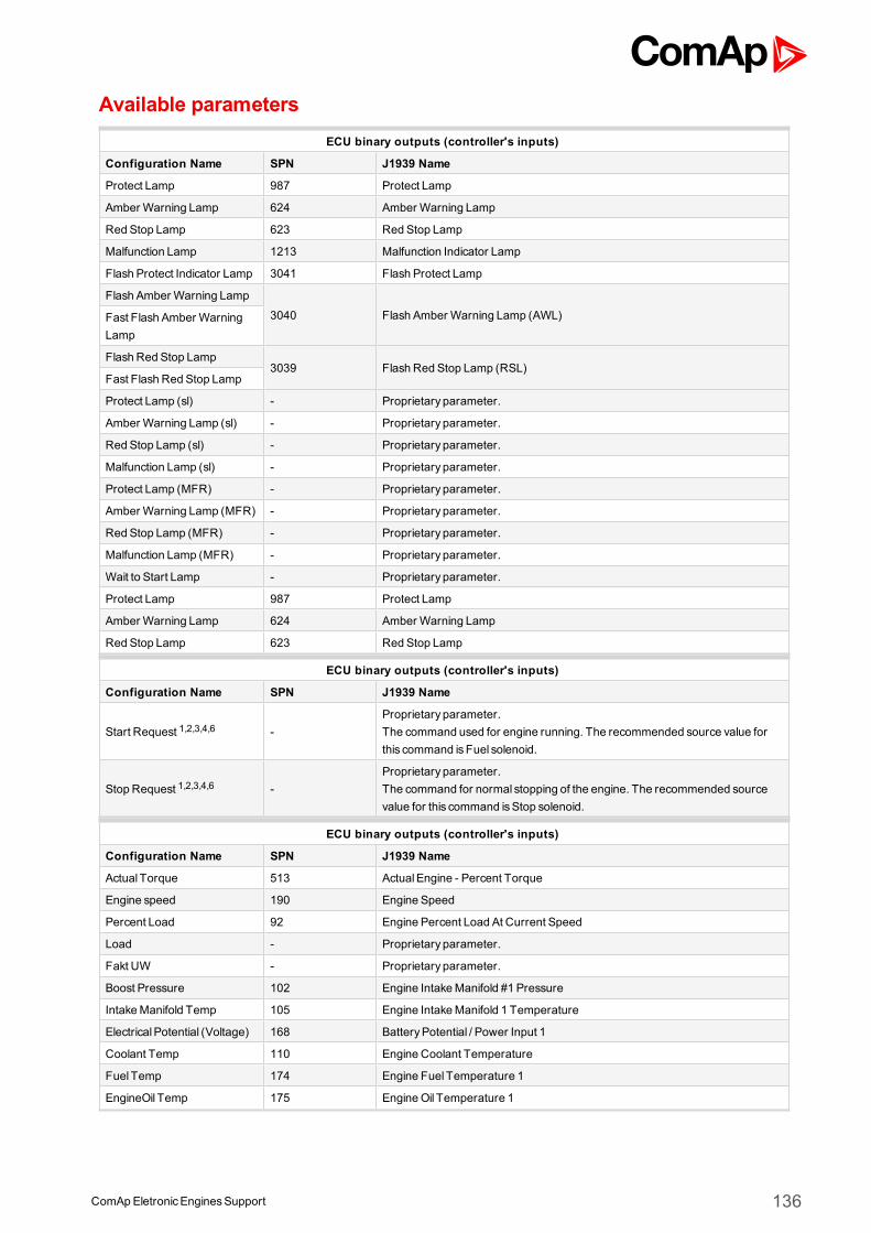
ComApEletronicEnginesSupport 136
Available parametersECU binary outputs (controller's inputs)
Configuration Name SPN J1939 Name
Protect Lamp 987 Protect Lamp
Amber Warning Lamp 624 Amber Warning Lamp
Red Stop Lamp 623 Red Stop Lamp
Malfunction Lamp 1213 Malfunction Indicator Lamp
Flash Protect Indicator Lamp 3041 Flash Protect Lamp
Flash Amber Warning Lamp
3040 Flash Amber Warning Lamp (AWL)Fast Flash Amber WarningLamp
Flash Red Stop Lamp3039 Flash Red Stop Lamp (RSL)
Fast Flash Red Stop Lamp
Protect Lamp (sl) - Proprietary parameter.
Amber Warning Lamp (sl) - Proprietary parameter.
Red Stop Lamp (sl) - Proprietary parameter.
Malfunction Lamp (sl) - Proprietary parameter.
Protect Lamp (MFR) - Proprietary parameter.
Amber Warning Lamp (MFR) - Proprietary parameter.
Red Stop Lamp (MFR) - Proprietary parameter.
Malfunction Lamp (MFR) - Proprietary parameter.
Wait to Start Lamp - Proprietary parameter.
Protect Lamp 987 Protect Lamp
Amber Warning Lamp 624 Amber Warning Lamp
Red Stop Lamp 623 Red Stop Lamp
ECU binary outputs (controller's inputs)
Configuration Name SPN J1939 Name
Start Request 1,2,3,4,6 -Proprietary parameter.The command used for engine running. The recommended source value forthis command isFuel solenoid.
Stop Request 1,2,3,4,6 -Proprietary parameter.The command for normal stopping of the engine. The recommended sourcevalue for this command isStop solenoid.
ECU binary outputs (controller's inputs)
Configuration Name SPN J1939 Name
Actual Torque 513 ActualEngine - Percent Torque
Engine speed 190 Engine Speed
Percent Load 92 Engine Percent Load At Current Speed
Load - Proprietary parameter.
Fakt UW - Proprietary parameter.
Boost Pressure 102 Engine IntakeManifold #1 Pressure
IntakeManifold Temp 105 Engine IntakeManifold 1 Temperature
ElectricalPotential (Voltage) 168 BatteryPotential / Power Input 1
Coolant Temp 110 Engine Coolant Temperature
Fuel Temp 174 Engine Fuel Temperature 1
EngineOil Temp 175 EngineOil Temperature 1
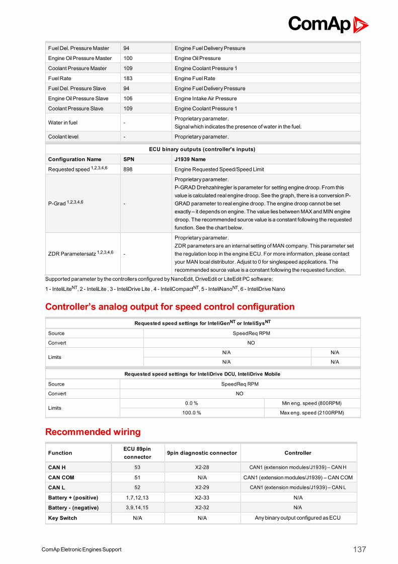
ComApEletronicEnginesSupport 137
FuelDel. PressureMaster 94 Engine FuelDeliveryPressure
EngineOil PressureMaster 100 EngineOil Pressure
Coolant PressureMaster 109 Engine Coolant Pressure 1
FuelRate 183 Engine FuelRate
FuelDel. Pressure Slave 94 Engine FuelDeliveryPressure
EngineOil Pressure Slave 106 Engine Intake Air Pressure
Coolant Pressure Slave 109 Engine Coolant Pressure 1
Water in fuel -Proprietary parameter.Signalwhich indicates the presence of water in the fuel.
Coolant level - Proprietary parameter.
ECU binary outputs (controller's inputs)
Configuration Name SPN J1939 Name
Requested speed 1,2,3,4,6 898 Engine Requested Speed/Speed Limit
P-Grad 1,2,3,4,6 -
Proprietary parameter.P-GRAD Drehzahlregler is parameter for setting engine droop. From thisvalue is calculated real engine droop. See the graph, there is a conversion P-GRAD parameter to real engine droop. The engine droop cannot be setexactly – it dependson engine. The value lies betweenMAXandMIN enginedroop. The recommended source value is a constant following the requestedfunction. See the chart below.
ZDR Parametersatz 1,2,3,4,6 -
Proprietary parameter.ZDR parameters are an internal setting of MAN company. This parameter setthe regulation loop in the engine ECU. For more information, please contactyour MAN local distributor. Adjust to 0 for singlespeed applications. Therecommended source value is a constant following the requested function.
Supported parameter by the controllers configured byNanoEdit, DriveEdit or LiteEdit PC software:
1 - InteliLiteNT, 2 - InteliLite , 3 - InteliDrive Lite , 4 - InteliCompactNT, 5 - InteliNanoNT, 6 - InteliDrive Nano
Controller’s analog output for speed control configurationRequested speed settings for InteliGenNT or InteliSysNT
Source SpeedReq RPM
Convert NO
LimitsN/A N/A
N/A N/A
Requested speed settings for InteliDrive DCU, InteliDrive Mobile
Source SpeedReq RPM
Convert NO
Limits0.0 % Min eng. speed (800RPM)
100.0 % Max eng. speed (2100RPM)
Recommended wiring
FunctionECU 89pinconnector
9pin diagnostic connector Controller
CAN H 53 X2-28 CAN1 (extension modules/J1939) – CANH
CAN COM 51 N/A CAN1 (extensionmodules/J1939) – CAN COM
CAN L 52 X2-29 CAN1 (extension modules/J1939) – CANL
Battery + (positive) 1,7,12,13 X2-33 N/A
Battery - (negative) 3,9,14,15 X2-32 N/A
Key Switch N/A N/A Anybinary output configured asECU
ComApEletronicEnginesSupport 138
PwrRelay
Analog Speed Control N/A N/A SG OUT
Analog Speed Control N/A N/A SGCOM
Note:Controller ECU PwrRelay output can be used to activate Ignition (Kl.15).
Formore information about diagnostic connector layout see SAE - J1939 diagnostic connector on page 17.Available list of texts of fault codes see EDC Master, EDC Slave and MFR interface system on page 280.
DiagnosticThe controller shows in the alarm list for each fault: Text message or fault code number SPN number on thebottom row OC number on the bottom row which says from where comes this fault:
0 - EDC Master
1 - EDC Slave
39 - MFR FMI number in the right bottom corner
Fault details are displayed in the bottom row when fault is selected with > mark in the list of faults by Up/Downarrows.
3.16.3 Data Logger
Image 4.43 Data Logger
Controllers that support the Data Logger
Controller family Selection in PC software
InteliSysNTor InteliGenNT MAN data logger
InteliDrive DCU or InteliDriveMobile MAN data logger
InteliDrive Lite MAN data logger
InteliLiteNTor InteliCompactNT not supported
InteliLite not supporte
InteliNanoNT not supported
InteliDrive Nano not supported
Available parametersECU binary outputs (controller's inputs)
Configuration Name SPN J1939 Name
Amber Warning Lamp - Proprietary parameter.
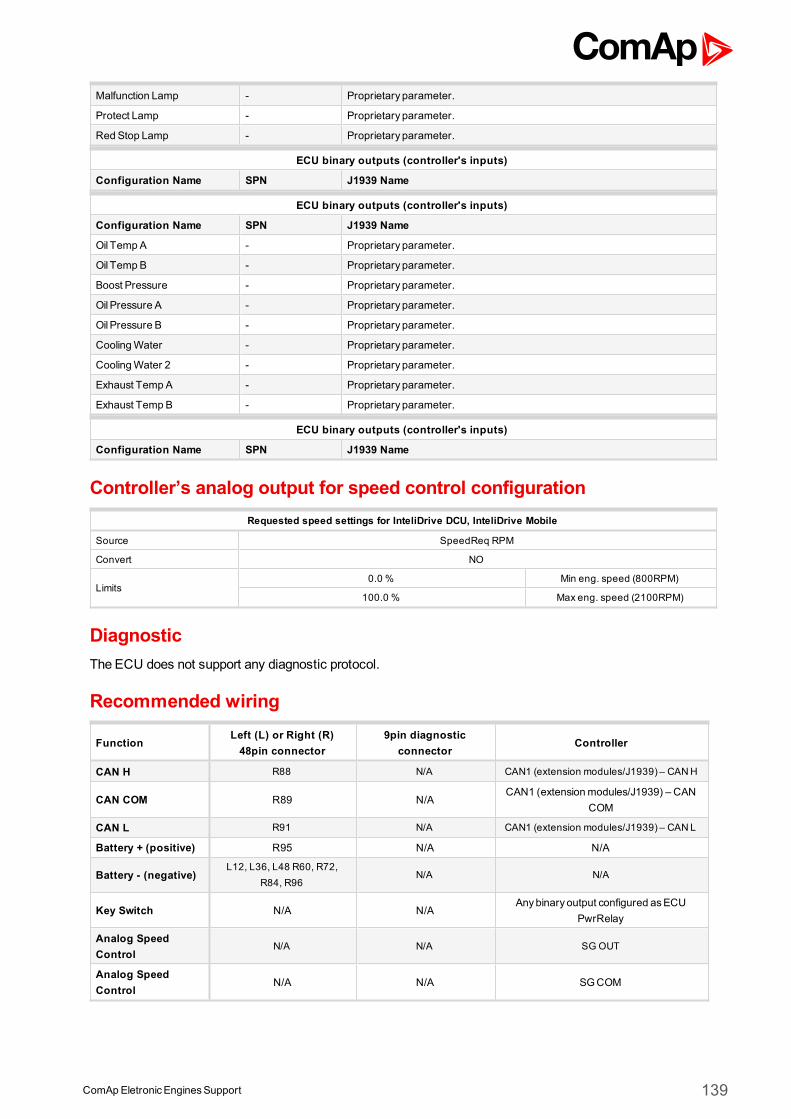
ComApEletronicEnginesSupport 139
Malfunction Lamp - Proprietary parameter.
Protect Lamp - Proprietary parameter.
Red Stop Lamp - Proprietary parameter.
ECU binary outputs (controller's inputs)
Configuration Name SPN J1939 Name
ECU binary outputs (controller's inputs)
Configuration Name SPN J1939 Name
Oil Temp A - Proprietary parameter.
Oil Temp B - Proprietary parameter.
Boost Pressure - Proprietary parameter.
Oil Pressure A - Proprietary parameter.
Oil Pressure B - Proprietary parameter.
CoolingWater - Proprietary parameter.
CoolingWater 2 - Proprietary parameter.
Exhaust Temp A - Proprietary parameter.
Exhaust Temp B - Proprietary parameter.
ECU binary outputs (controller's inputs)
Configuration Name SPN J1939 Name
Controller’s analog output for speed control configurationRequested speed settings for InteliDrive DCU, InteliDrive Mobile
Source SpeedReq RPM
Convert NO
Limits0.0 % Min eng. speed (800RPM)
100.0 % Max eng. speed (2100RPM)
DiagnosticThe ECU does not support any diagnostic protocol.
Recommended wiring
FunctionLeft (L) or Right (R)48pin connector
9pin diagnosticconnector
Controller
CAN H R88 N/A CAN1 (extension modules/J1939) – CANH
CAN COM R89 N/ACAN1 (extensionmodules/J1939) – CAN
COM
CAN L R91 N/A CAN1 (extension modules/J1939) – CANL
Battery + (positive) R95 N/A N/A
Battery - (negative)L12, L36, L48 R60, R72,
R84, R96N/A N/A
Key Switch N/A N/AAnybinary output configured asECU
PwrRelay
Analog SpeedControl
N/A N/A SG OUT
Analog SpeedControl
N/A N/A SGCOM
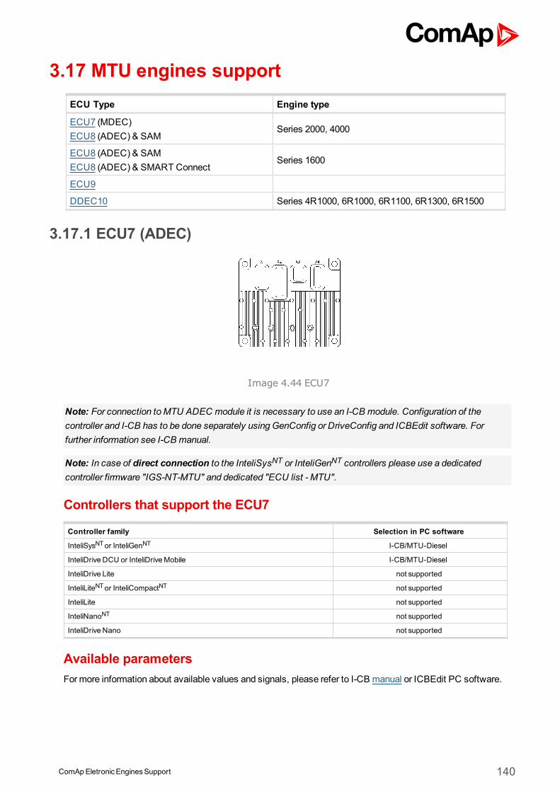
ComApEletronicEnginesSupport 140
3.17 MTU engines supportECU Type Engine type
ECU7 (MDEC)ECU8 (ADEC) & SAM
Series 2000, 4000
ECU8 (ADEC) & SAMECU8 (ADEC) & SMART Connect
Series 1600
ECU9
DDEC10 Series 4R1000, 6R1000, 6R1100, 6R1300, 6R1500
3.17.1 ECU7 (ADEC)
Image 4.44 ECU7
Note: For connection toMTU ADEC module it is necessary to use an I-CB module. Configuration of thecontroller and I-CB has to be done separately using GenConfig or DriveConfig and ICBEdit software. Forfurther information see I-CB manual.
Note: In case of direct connection to the InteliSysNT or InteliGenNT controllers please use a dedicatedcontroller firmware "IGS-NT-MTU" and dedicated "ECU list - MTU".
Controllers that support the ECU7
Controller family Selection in PC software
InteliSysNTor InteliGenNT I-CB/MTU-Diesel
InteliDrive DCU or InteliDriveMobile I-CB/MTU-Diesel
InteliDrive Lite not supported
InteliLiteNTor InteliCompactNT not supported
InteliLite not supported
InteliNanoNT not supported
InteliDrive Nano not supported
Available parametersFormore information about available values and signals, please refer to I-CB manual or ICBEdit PC software.
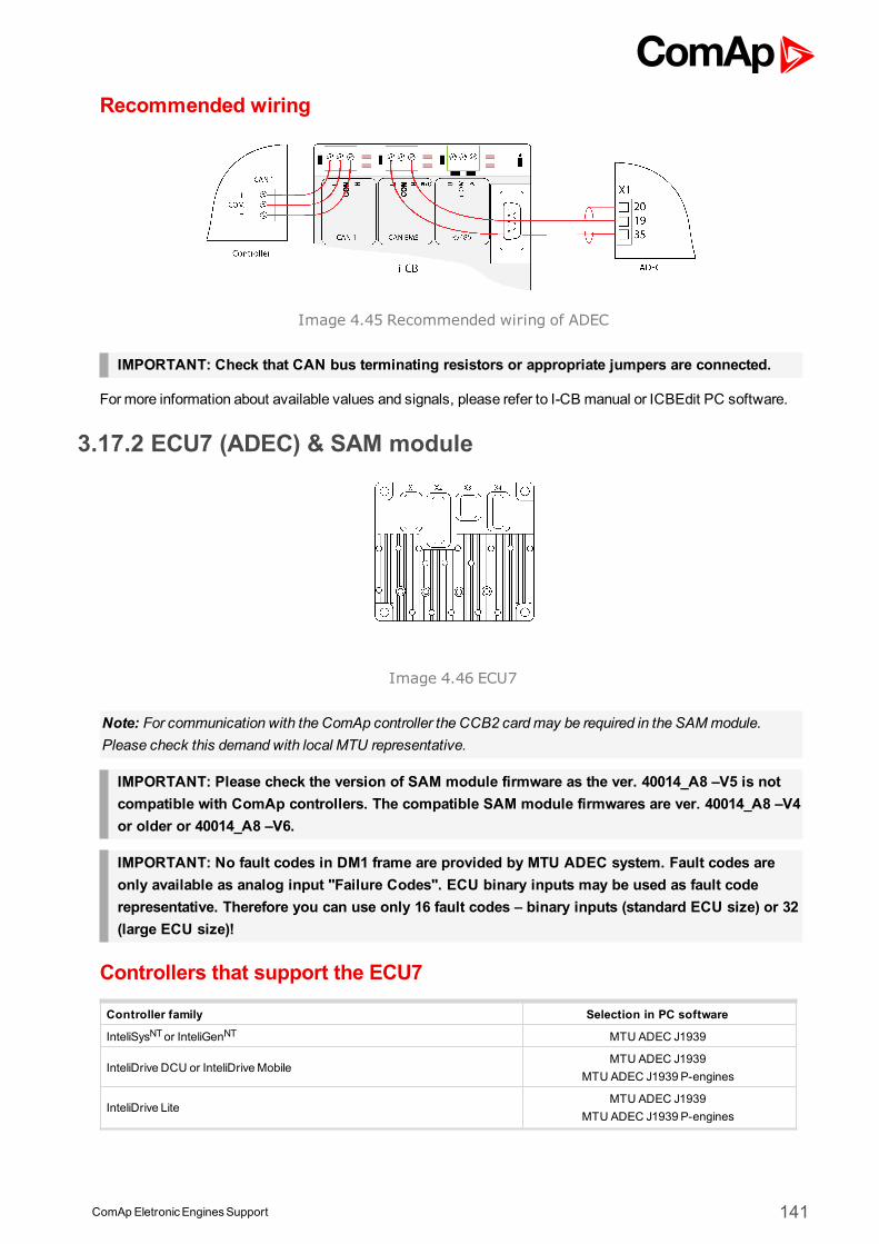
ComApEletronicEnginesSupport 141
Recommended wiring
Image 4.45 Recommended wiring of ADEC
IMPORTANT: Check that CAN bus terminating resistors or appropriate jumpers are connected.
Formore information about available values and signals, please refer to I-CB manual or ICBEdit PC software.
3.17.2 ECU7 (ADEC) & SAM module
Image 4.46 ECU7
Note: For communication with the ComAp controller the CCB2 cardmay be required in the SAMmodule.Please check this demand with local MTU representative.
IMPORTANT: Please check the version of SAM module firmware as the ver. 40014_A8 –V5 is notcompatible with ComAp controllers. The compatible SAM module firmwares are ver. 40014_A8 –V4or older or 40014_A8 –V6.
IMPORTANT: No fault codes in DM1 frame are provided by MTU ADEC system. Fault codes areonly available as analog input "Failure Codes". ECU binary inputs may be used as fault coderepresentative. Therefore you can use only 16 fault codes – binary inputs (standard ECU size) or 32(large ECU size)!
Controllers that support the ECU7
Controller family Selection in PC software
InteliSysNTor InteliGenNT MTU ADEC J1939
InteliDrive DCU or InteliDriveMobileMTU ADEC J1939
MTU ADEC J1939 P-engines
InteliDrive LiteMTU ADEC J1939
MTU ADEC J1939 P-engines
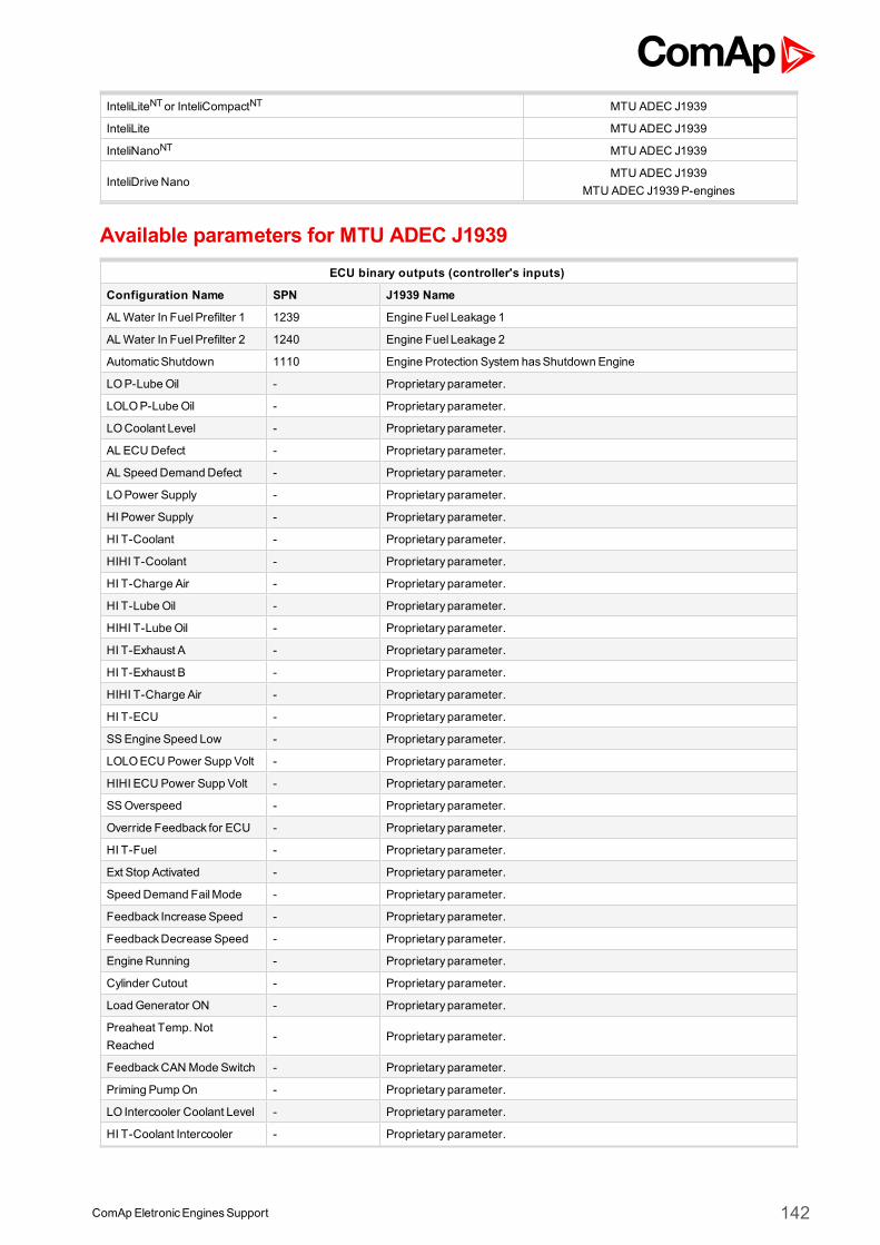
ComApEletronicEnginesSupport 142
InteliLiteNTor InteliCompactNT MTU ADEC J1939
InteliLite MTU ADEC J1939
InteliNanoNT MTU ADEC J1939
InteliDrive NanoMTU ADEC J1939
MTU ADEC J1939 P-engines
Available parameters for MTU ADEC J1939ECU binary outputs (controller's inputs)
Configuration Name SPN J1939 Name
ALWater In FuelPrefilter 1 1239 Engine Fuel Leakage 1
ALWater In FuelPrefilter 2 1240 Engine Fuel Leakage 2
AutomaticShutdown 1110 Engine Protection System hasShutdown Engine
LOP-LubeOil - Proprietary parameter.
LOLOP-LubeOil - Proprietary parameter.
LOCoolant Level - Proprietary parameter.
AL ECU Defect - Proprietary parameter.
AL Speed DemandDefect - Proprietary parameter.
LOPower Supply - Proprietary parameter.
HI Power Supply - Proprietary parameter.
HI T-Coolant - Proprietary parameter.
HIHI T-Coolant - Proprietary parameter.
HI T-Charge Air - Proprietary parameter.
HI T-LubeOil - Proprietary parameter.
HIHI T-LubeOil - Proprietary parameter.
HI T-Exhaust A - Proprietary parameter.
HI T-Exhaust B - Proprietary parameter.
HIHI T-Charge Air - Proprietary parameter.
HI T-ECU - Proprietary parameter.
SSEngine Speed Low - Proprietary parameter.
LOLOECU Power Supp Volt - Proprietary parameter.
HIHI ECU Power Supp Volt - Proprietary parameter.
SSOverspeed - Proprietary parameter.
Override Feedback for ECU - Proprietary parameter.
HI T-Fuel - Proprietary parameter.
Ext Stop Activated - Proprietary parameter.
Speed Demand FailMode - Proprietary parameter.
Feedback Increase Speed - Proprietary parameter.
FeedbackDecrease Speed - Proprietary parameter.
Engine Running - Proprietary parameter.
Cylinder Cutout - Proprietary parameter.
LoadGenerator ON - Proprietary parameter.
Preaheat Temp. NotReached
- Proprietary parameter.
FeedbackCANMode Switch - Proprietary parameter.
Priming PumpOn - Proprietary parameter.
LO Intercooler Coolant Level - Proprietary parameter.
HI T-Coolant Intercooler - Proprietary parameter.
ComApEletronicEnginesSupport 143
AL Prelubrication Fault - Proprietary parameter.
AL Start Speed Not Reached - Proprietary parameter.
AL Runup Speed NotReached
- Proprietary parameter.
AL Idle Speed Not Reached - Proprietary parameter.
HI Pressure 1 - Proprietary parameter.
HI Pressure 2 - Proprietary parameter.
HI LevelDay-Tank - Proprietary parameter.
LOLevelDay-Tank - Proprietary parameter.
HI LevelHolding-Tank - Proprietary parameter.
LOLevelHolding-Tank - Proprietary parameter.
HI T-Winding 1 - Proprietary parameter.
HI T-Winding 2 - Proprietary parameter.
HI T-Winding 3 - Proprietary parameter.
HI T-Ambient - Proprietary parameter.
T-Generator Warning - Proprietary parameter.
Wait To Start Lamp 1081 EngineWait to Start Lamp
Protect Lamp 987 Protect Lamp
Amber Warning Lamp 624 Amber Warning Lamp
Red Stop Lamp 623 Red Stop Lamp
Malfunction Lamp 1213 Malfunction Indicator Lamp
Flash Protect Indicator Lamp 3041 Flash Protect Lamp
Flash Amber Warning Lamp
3040 Flash Amber Warning Lamp (AWL)Fast Flash Amber WarningLamp
Flash Red Stop Lamp3039 Flash Red Stop Lamp (RSL)
Fast Flash Red Stop Lamp
ECU binary outputs (controller's inputs)
Configuration Name SPN J1939 Name
Disable Cylinder Cut Out 2 - Proprietary parameter.
Request Test Overspeed - Proprietary parameter.
AlarmReset 1,2,3,4 -Proprietary parameter.The command for Reset ECU Alarms. The recommended source value for thiscommand isFltResButnEcho.
Speed Setting Limit Active -Proprietary parameter.For more information about this signal contact localMTU representative.
Mode Switch - Proprietary parameter.
Governor ParameterSetSelect.
- Proprietary parameter.
Intermittent Oil Priming - Proprietary parameter.
Engine Start 1,2,3,4,5,6 -Proprietary parameter.The command used for engine running. The recommended source value forthis command isStarter.
50/60Hz 1,2,3,4,5 -
Proprietary parameter.This feature gives the operator ability to switch the rated speed between 50Hzand 60Hz. The systemwill only react to a state transition while the Enginespeed is 0. The recommended source value for this command is Logical 0 for50Hzand Logical 1 for 60Hz.
Override 1237Engine ShutdownOverride SwitchSwitch signalwhich indicates the position of the engine shutdown override
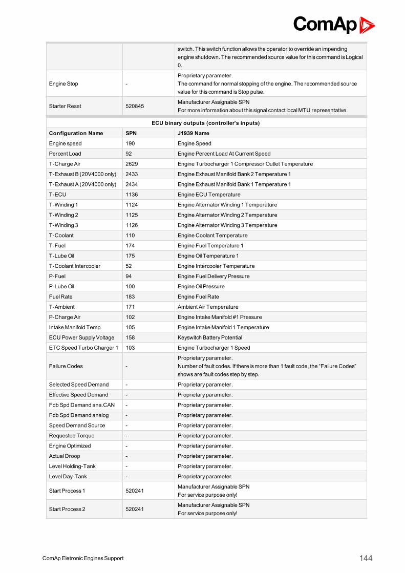
ComApEletronicEnginesSupport 144
switch. This switch function allows the operator to override an impendingengine shutdown. The recommended source value for this command is Logical0.
Engine Stop -Proprietary parameter.The command for normal stopping of the engine. The recommended sourcevalue for this command isStop pulse.
Starter Reset 520845Manufacturer Assignable SPNFor more information about this signal contact localMTU representative.
ECU binary outputs (controller's inputs)
Configuration Name SPN J1939 Name
Engine speed 190 Engine Speed
Percent Load 92 Engine Percent Load At Current Speed
T-Charge Air 2629 Engine Turbocharger 1 Compressor Outlet Temperature
T-Exhaust B (20V4000 only) 2433 Engine Exhaust Manifold Bank2 Temperature 1
T-Exhaust A (20V4000 only) 2434 Engine Exhaust Manifold Bank1 Temperature 1
T-ECU 1136 Engine ECU Temperature
T-Winding 1 1124 Engine Alternator Winding 1 Temperature
T-Winding 2 1125 Engine Alternator Winding 2 Temperature
T-Winding 3 1126 Engine Alternator Winding 3 Temperature
T-Coolant 110 Engine Coolant Temperature
T-Fuel 174 Engine Fuel Temperature 1
T-LubeOil 175 EngineOil Temperature 1
T-Coolant Intercooler 52 Engine Intercooler Temperature
P-Fuel 94 Engine FuelDeliveryPressure
P-LubeOil 100 EngineOil Pressure
FuelRate 183 Engine FuelRate
T-Ambient 171 Ambient Air Temperature
P-Charge Air 102 Engine IntakeManifold #1 Pressure
IntakeManifold Temp 105 Engine IntakeManifold 1 Temperature
ECU Power SupplyVoltage 158 Keyswitch BatteryPotential
ETC Speed Turbo Charger 1 103 Engine Turbocharger 1 Speed
Failure Codes -Proprietary parameter.Number of fault codes. If there ismore than 1 fault code, the “Failure Codes”showsare fault codes step by step.
Selected Speed Demand - Proprietary parameter.
Effective Speed Demand - Proprietary parameter.
Fdb SpdDemand ana.CAN - Proprietary parameter.
Fdb SpdDemand analog - Proprietary parameter.
Speed Demand Source - Proprietary parameter.
Requested Torque - Proprietary parameter.
EngineOptimized - Proprietary parameter.
ActualDroop - Proprietary parameter.
LevelHolding-Tank - Proprietary parameter.
LevelDay-Tank - Proprietary parameter.
Start Process1 520241Manufacturer Assignable SPNFor service purpose only!
Start Process2 520241Manufacturer Assignable SPNFor service purpose only!
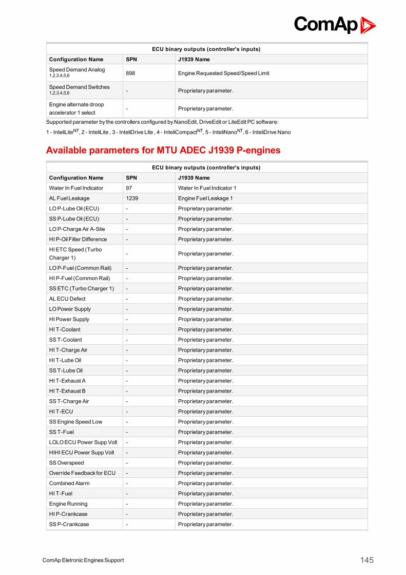
ComApEletronicEnginesSupport 145
ECU binary outputs (controller's inputs)
Configuration Name SPN J1939 Name
Speed Demand Analog1,2,3,4,5,6 898 Engine Requested Speed/Speed Limit
Speed Demand Switches1,2,3,4,5,6 - Proprietary parameter.
Engine alternate droopaccelerator 1 select
- Proprietary parameter.
Supported parameter by the controllers configured byNanoEdit, DriveEdit or LiteEdit PC software:
1 - InteliLiteNT, 2 - InteliLite , 3 - InteliDrive Lite , 4 - InteliCompactNT, 5 - InteliNanoNT, 6 - InteliDrive Nano
Available parameters for MTU ADEC J1939 P-enginesECU binary outputs (controller's inputs)
Configuration Name SPN J1939 Name
Water In Fuel Indicator 97 Water In Fuel Indicator 1
AL Fuel Leakage 1239 Engine Fuel Leakage 1
LOP-LubeOil (ECU) - Proprietary parameter.
SSP-LubeOil (ECU) - Proprietary parameter.
LOP-Charge Air A-Site - Proprietary parameter.
HI P-Oil Filter Difference - Proprietary parameter.
HI ETC Speed (TurboCharger 1)
- Proprietary parameter.
LOP-Fuel (CommonRail) - Proprietary parameter.
HI P-Fuel (CommonRail) - Proprietary parameter.
SSETC (Turbo Charger 1) - Proprietary parameter.
AL ECU Defect - Proprietary parameter.
LOPower Supply - Proprietary parameter.
HI Power Supply - Proprietary parameter.
HI T-Coolant - Proprietary parameter.
SST-Coolant - Proprietary parameter.
HI T-Charge Air - Proprietary parameter.
HI T-LubeOil - Proprietary parameter.
SST-LubeOil - Proprietary parameter.
HI T-Exhaust A - Proprietary parameter.
HI T-Exhaust B - Proprietary parameter.
SST-Charge Air - Proprietary parameter.
HI T-ECU - Proprietary parameter.
SSEngine Speed Low - Proprietary parameter.
SST-Fuel - Proprietary parameter.
LOLOECU Power Supp Volt - Proprietary parameter.
HIHI ECU Power Supp Volt - Proprietary parameter.
SSOverspeed - Proprietary parameter.
Override Feedback for ECU - Proprietary parameter.
Combined Alarm - Proprietary parameter.
HI T-Fuel - Proprietary parameter.
Engine Running - Proprietary parameter.
HI P-Crankcase - Proprietary parameter.
SSP-Crankcase - Proprietary parameter.
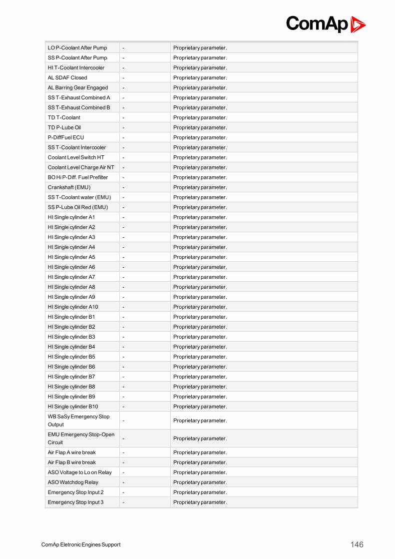
ComApEletronicEnginesSupport 146
LOP-Coolant After Pump - Proprietary parameter.
SSP-Coolant After Pump - Proprietary parameter.
HI T-Coolant Intercooler - Proprietary parameter.
AL SDAF Closed - Proprietary parameter.
AL Barring Gear Engaged - Proprietary parameter.
SST-Exhaust Combined A - Proprietary parameter.
SST-Exhaust Combined B - Proprietary parameter.
TD T-Coolant - Proprietary parameter.
TD P-LubeOil - Proprietary parameter.
P-DiffFuelECU - Proprietary parameter.
SST-Coolant Intercooler - Proprietary parameter.
Coolant LevelSwitch HT - Proprietary parameter.
Coolant LevelCharge Air NT - Proprietary parameter.
BOHiP-Diff. FuelPrefilter - Proprietary parameter.
Crankshaft (EMU) - Proprietary parameter.
SST-Coolant water (EMU) - Proprietary parameter.
SSP-LubeOilRed (EMU) - Proprietary parameter.
HI Single cylinder A1 - Proprietary parameter.
HI Single cylinder A2 - Proprietary parameter.
HI Single cylinder A3 - Proprietary parameter.
HI Single cylinder A4 - Proprietary parameter.
HI Single cylinder A5 - Proprietary parameter.
HI Single cylinder A6 - Proprietary parameter.
HI Single cylinder A7 - Proprietary parameter.
HI Single cylinder A8 - Proprietary parameter.
HI Single cylinder A9 - Proprietary parameter.
HI Single cylinder A10 - Proprietary parameter.
HI Single cylinder B1 - Proprietary parameter.
HI Single cylinder B2 - Proprietary parameter.
HI Single cylinder B3 - Proprietary parameter.
HI Single cylinder B4 - Proprietary parameter.
HI Single cylinder B5 - Proprietary parameter.
HI Single cylinder B6 - Proprietary parameter.
HI Single cylinder B7 - Proprietary parameter.
HI Single cylinder B8 - Proprietary parameter.
HI Single cylinder B9 - Proprietary parameter.
HI Single cylinder B10 - Proprietary parameter.
WBSaSyEmergencyStopOutput
- Proprietary parameter.
EMU EmergencyStop-OpenCircuit
- Proprietary parameter.
Air Flap Awire break - Proprietary parameter.
Air Flap Bwire break - Proprietary parameter.
ASOVoltage to Lo on Relay - Proprietary parameter.
ASOWatchdog Relay - Proprietary parameter.
EmergencyStop Input 2 - Proprietary parameter.
EmergencyStop Input 3 - Proprietary parameter.
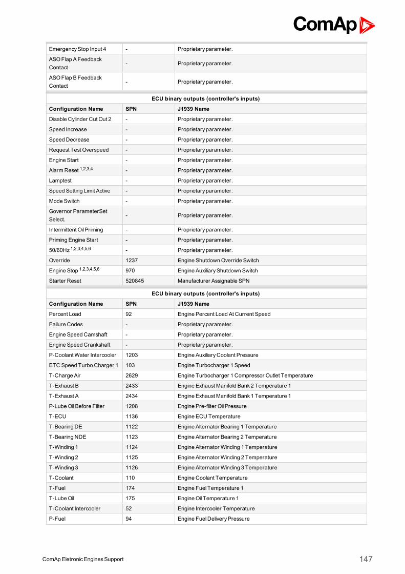
ComApEletronicEnginesSupport 147
EmergencyStop Input 4 - Proprietary parameter.
ASOFlap AFeedbackContact
- Proprietary parameter.
ASOFlap BFeedbackContact
- Proprietary parameter.
ECU binary outputs (controller's inputs)
Configuration Name SPN J1939 Name
Disable Cylinder Cut Out 2 - Proprietary parameter.
Speed Increase - Proprietary parameter.
Speed Decrease - Proprietary parameter.
Request Test Overspeed - Proprietary parameter.
Engine Start - Proprietary parameter.
AlarmReset 1,2,3,4 - Proprietary parameter.
Lamptest - Proprietary parameter.
Speed Setting Limit Active - Proprietary parameter.
Mode Switch - Proprietary parameter.
Governor ParameterSetSelect.
- Proprietary parameter.
Intermittent Oil Priming - Proprietary parameter.
Priming Engine Start - Proprietary parameter.
50/60Hz 1,2,3,4,5,6 - Proprietary parameter.
Override 1237 Engine ShutdownOverride Switch
Engine Stop 1,2,3,4,5,6 970 Engine AuxiliaryShutdown Switch
Starter Reset 520845 Manufacturer Assignable SPN
ECU binary outputs (controller's inputs)
Configuration Name SPN J1939 Name
Percent Load 92 Engine Percent Load At Current Speed
Failure Codes - Proprietary parameter.
Engine Speed Camshaft - Proprietary parameter.
Engine Speed Crankshaft - Proprietary parameter.
P-CoolantWater Intercooler 1203 Engine AuxiliaryCoolant Pressure
ETC Speed Turbo Charger 1 103 Engine Turbocharger 1 Speed
T-Charge Air 2629 Engine Turbocharger 1 Compressor Outlet Temperature
T-Exhaust B 2433 Engine Exhaust Manifold Bank2 Temperature 1
T-Exhaust A 2434 Engine Exhaust Manifold Bank1 Temperature 1
P-LubeOil Before Filter 1208 Engine Pre-filter Oil Pressure
T-ECU 1136 Engine ECU Temperature
T-Bearing DE 1122 Engine Alternator Bearing 1 Temperature
T-Bearing NDE 1123 Engine Alternator Bearing 2 Temperature
T-Winding 1 1124 Engine Alternator Winding 1 Temperature
T-Winding 2 1125 Engine Alternator Winding 2 Temperature
T-Winding 3 1126 Engine Alternator Winding 3 Temperature
T-Coolant 110 Engine Coolant Temperature
T-Fuel 174 Engine Fuel Temperature 1
T-LubeOil 175 EngineOil Temperature 1
T-Coolant Intercooler 52 Engine Intercooler Temperature
P-Fuel 94 Engine FuelDeliveryPressure
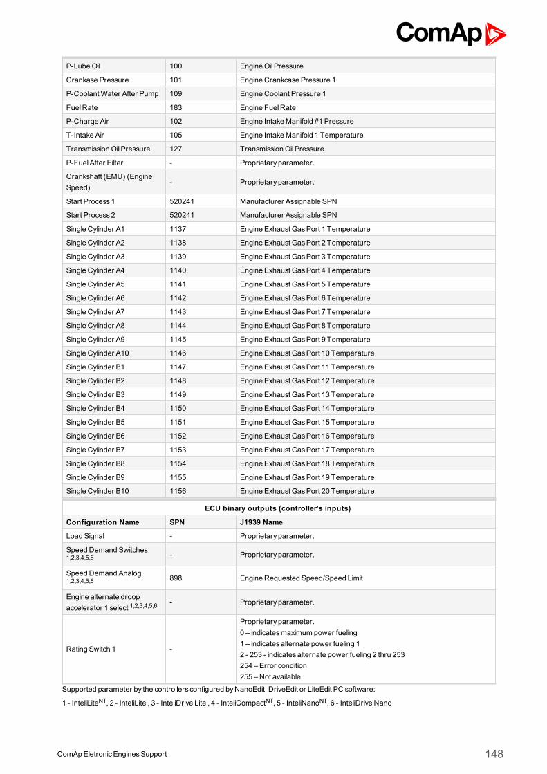
ComApEletronicEnginesSupport 148
P-LubeOil 100 EngineOil Pressure
Crankase Pressure 101 Engine Crankcase Pressure 1
P-CoolantWater After Pump 109 Engine Coolant Pressure 1
FuelRate 183 Engine FuelRate
P-Charge Air 102 Engine IntakeManifold #1 Pressure
T-Intake Air 105 Engine IntakeManifold 1 Temperature
TransmissionOil Pressure 127 TransmissionOil Pressure
P-FuelAfter Filter - Proprietary parameter.
Crankshaft (EMU) (EngineSpeed)
- Proprietary parameter.
Start Process1 520241 Manufacturer Assignable SPN
Start Process2 520241 Manufacturer Assignable SPN
Single Cylinder A1 1137 Engine Exhaust GasPort 1 Temperature
Single Cylinder A2 1138 Engine Exhaust GasPort 2 Temperature
Single Cylinder A3 1139 Engine Exhaust GasPort 3 Temperature
Single Cylinder A4 1140 Engine Exhaust GasPort 4 Temperature
Single Cylinder A5 1141 Engine Exhaust GasPort 5 Temperature
Single Cylinder A6 1142 Engine Exhaust GasPort 6 Temperature
Single Cylinder A7 1143 Engine Exhaust GasPort 7 Temperature
Single Cylinder A8 1144 Engine Exhaust GasPort 8 Temperature
Single Cylinder A9 1145 Engine Exhaust GasPort 9 Temperature
Single Cylinder A10 1146 Engine Exhaust GasPort 10 Temperature
Single Cylinder B1 1147 Engine Exhaust GasPort 11 Temperature
Single Cylinder B2 1148 Engine Exhaust GasPort 12 Temperature
Single Cylinder B3 1149 Engine Exhaust GasPort 13 Temperature
Single Cylinder B4 1150 Engine Exhaust GasPort 14 Temperature
Single Cylinder B5 1151 Engine Exhaust GasPort 15 Temperature
Single Cylinder B6 1152 Engine Exhaust GasPort 16 Temperature
Single Cylinder B7 1153 Engine Exhaust GasPort 17 Temperature
Single Cylinder B8 1154 Engine Exhaust GasPort 18 Temperature
Single Cylinder B9 1155 Engine Exhaust GasPort 19 Temperature
Single Cylinder B10 1156 Engine Exhaust GasPort 20 Temperature
ECU binary outputs (controller's inputs)
Configuration Name SPN J1939 Name
Load Signal - Proprietary parameter.
Speed Demand Switches1,2,3,4,5,6 - Proprietary parameter.
Speed Demand Analog1,2,3,4,5,6 898 Engine Requested Speed/Speed Limit
Engine alternate droopaccelerator 1 select 1,2,3,4,5,6
- Proprietary parameter.
Rating Switch 1 -
Proprietary parameter.0 – indicatesmaximum power fueling1 – indicatesalternate power fueling 12 - 253 - indicatesalternate power fueling 2 thru 253254 – Error condition255 – Not available
Supported parameter by the controllers configured byNanoEdit, DriveEdit or LiteEdit PC software:
1 - InteliLiteNT, 2 - InteliLite , 3 - InteliDrive Lite , 4 - InteliCompactNT, 5 - InteliNanoNT, 6 - InteliDrive Nano
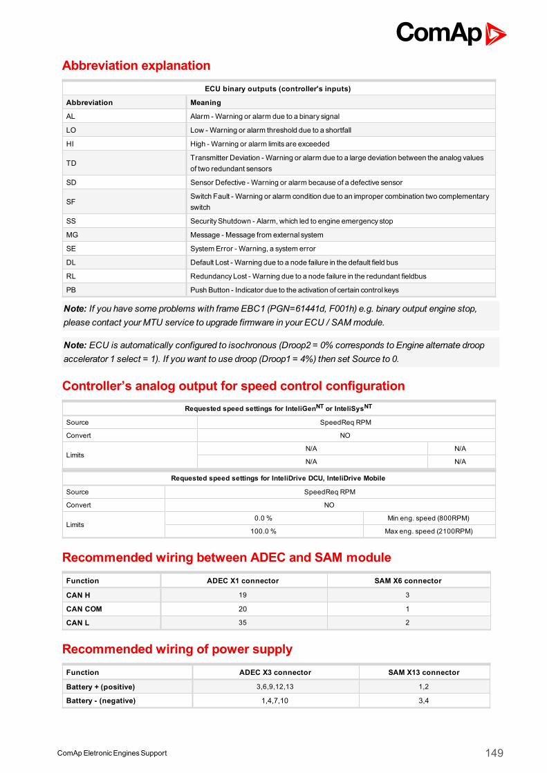
ComApEletronicEnginesSupport 149
Abbreviation explanationECU binary outputs (controller's inputs)
Abbreviation Meaning
AL Alarm - Warning or alarm due to a binary signal
LO Low - Warning or alarm threshold due to a shortfall
HI High - Warning or alarm limits are exceeded
TDTransmitter Deviation - Warning or alarm due to a large deviation between the analog valuesof two redundant sensors
SD Sensor Defective - Warning or alarm because of a defective sensor
SFSwitch Fault - Warning or alarm condition due to an improper combination two complementaryswitch
SS SecurityShutdown - Alarm, which led to engine emergency stop
MG Message - Message from external system
SE SystemError - Warning, a system error
DL Default Lost - Warning due to a node failure in the default field bus
RL RedundancyLost - Warning due to a node failure in the redundant fieldbus
PB Push Button - Indicator due to the activation of certain control keys
Note: If you have some problems with frame EBC1 (PGN=61441d, F001h) e.g. binary output engine stop,please contact your MTU service to upgrade firmware in your ECU / SAMmodule.
Note: ECU is automatically configured to isochronous (Droop2 = 0% corresponds to Engine alternate droopaccelerator 1 select = 1). If you want to use droop (Droop1 = 4%) then set Source to 0.
Controller’s analog output for speed control configurationRequested speed settings for InteliGenNT or InteliSysNT
Source SpeedReq RPM
Convert NO
LimitsN/A N/A
N/A N/A
Requested speed settings for InteliDrive DCU, InteliDrive Mobile
Source SpeedReq RPM
Convert NO
Limits0.0 % Min eng. speed (800RPM)
100.0 % Max eng. speed (2100RPM)
Recommended wiring between ADEC and SAM moduleFunction ADEC X1 connector SAM X6 connector
CAN H 19 3
CAN COM 20 1
CAN L 35 2
Recommended wiring of power supplyFunction ADEC X3 connector SAM X13 connector
Battery + (positive) 3,6,9,12,13 1,2
Battery - (negative) 1,4,7,10 3,4
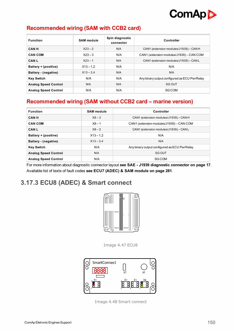
ComApEletronicEnginesSupport 150
Recommended wiring (SAM with CCB2 card)
Function SAM module9pin diagnostic
connectorController
CAN H X23 – 2 N/A CAN1 (extension modules/J1939) – CANH
CAN COM X23 – 3 N/A CAN1 (extensionmodules/J1939) – CAN COM
CAN L X23 – 1 N/A CAN1 (extension modules/J1939) – CANL
Battery + (positive) X13 – 1,2 N/A N/A
Battery - (negative) X13 – 3,4 N/A N/A
Key Switch N/A N/A Anybinary output configured asECU PwrRelay
Analog Speed Control N/A N/A SG OUT
Analog Speed Control N/A N/A SGCOM
Recommended wiring (SAM without CCB2 card – marine version)Function SAM module Controller
CAN H X8 – 3 CAN1 (extension modules/J1939) – CANH
CAN COM X8 – 1 CAN1 (extensionmodules/J1939) – CAN COM
CAN L X8 – 2 CAN1 (extension modules/J1939) – CANL
Battery + (positive) X13 – 1,2 N/A
Battery - (negative) X13 – 3,4 N/A
Key Switch N/A Anybinary output configured asECU PwrRelay
Analog Speed Control N/A SG OUT
Analog Speed Control N/A SGCOM
Formore information about diagnostic connector layout see SAE - J1939 diagnostic connector on page 17.Available list of texts of fault codes see ECU7 (ADEC) & SAM module on page 281.
3.17.3 ECU8 (ADEC) & Smart connect
Image 4.47 ECU8
Image 4.48 Smart connect
ComApEletronicEnginesSupport 151
Controllers that support the ECU8 & Smart connect
Controller family Selection in PC software
InteliSysNTor InteliGenNT MTU SMART Connect
InteliDrive DCU or InteliDriveMobile MTU SMART Connect
InteliDrive Lite MTU SMART Connect
InteliLiteNTor InteliCompactNT MTU SMART Connect
InteliLite MTU SMART Connect
InteliNanoNT MTU SMART Connect
InteliDrive Nano MTU SMART Connect
Available parametersECU binary outputs (controller's inputs)
Configuration Name SPN J1939 Name
Coolant Pre-heated State 3553 Engine Coolant Pre-heated State
Wait To Start Lamp 1081 EngineWait to Start Lamp
EPSEngine Shutdown 1110 Engine Protection System hasShutdown Engine
Safety&ProtectionOverStat 520202 Manufacturer Assignable SPN
MTU Engine Running State 520255 Manufacturer Assignable SPN
Engine Cylinder Cutoff 520252 Manufacturer Assignable SPN
LoadGenerator Status 520253 Manufacturer Assignable SPN
ExternalStop State 520833 Manufacturer Assignable SPN
Oper. Speed Up Switch Fdb 520205 Manufacturer Assignable SPN
Oper Speed Down Switch Fdb 520206 Manufacturer Assignable SPN
Speed Demand FailMode 520830 Manufacturer Assignable SPN
Protect Lamp 987 Protect Lamp
Amber Warning Lamp 624 Amber Warning Lamp
Red Stop Lamp 623 Red Stop Lamp
Malfunction Lamp 1213 Malfunction Indicator Lamp
Flash Protect Indicator Lamp 3041 Flash Protect Lamp
Flash Amber Warning Lamp3040 Flash Amber Warning Lamp (AWL)
Fast Flash Amber Warning Lamp
Flash Red Stop Lamp3039 Flash Red Stop Lamp (RSL)
Fast Flash Red Stop Lamp
ECU binary inputs (controller's outputs - commands)
Configuration Name SPN J1939 Name
Trip Group 1 - Proprietary parameter.
Engine Start Command 1,2,3,4,5,6 520192 Manufacturer Assignable SPN
Engine Stop Command 1,2,3,4,5,6 520193 Manufacturer Assignable SPN
EngSafety&ProtOverrideCmd1,2,3,4 520194 Manufacturer Assignable SPN
EngineOverspeed Test Cmd 520197 Manufacturer Assignable SPN
DisableEngCylCutoffCmd2 520834 Manufacturer Assignable SPN
IntermittentOilPrimingCmd 520835 Manufacturer Assignable SPN
EngSpdGovernorParamSwitch 520841 Manufacturer Assignable SPN
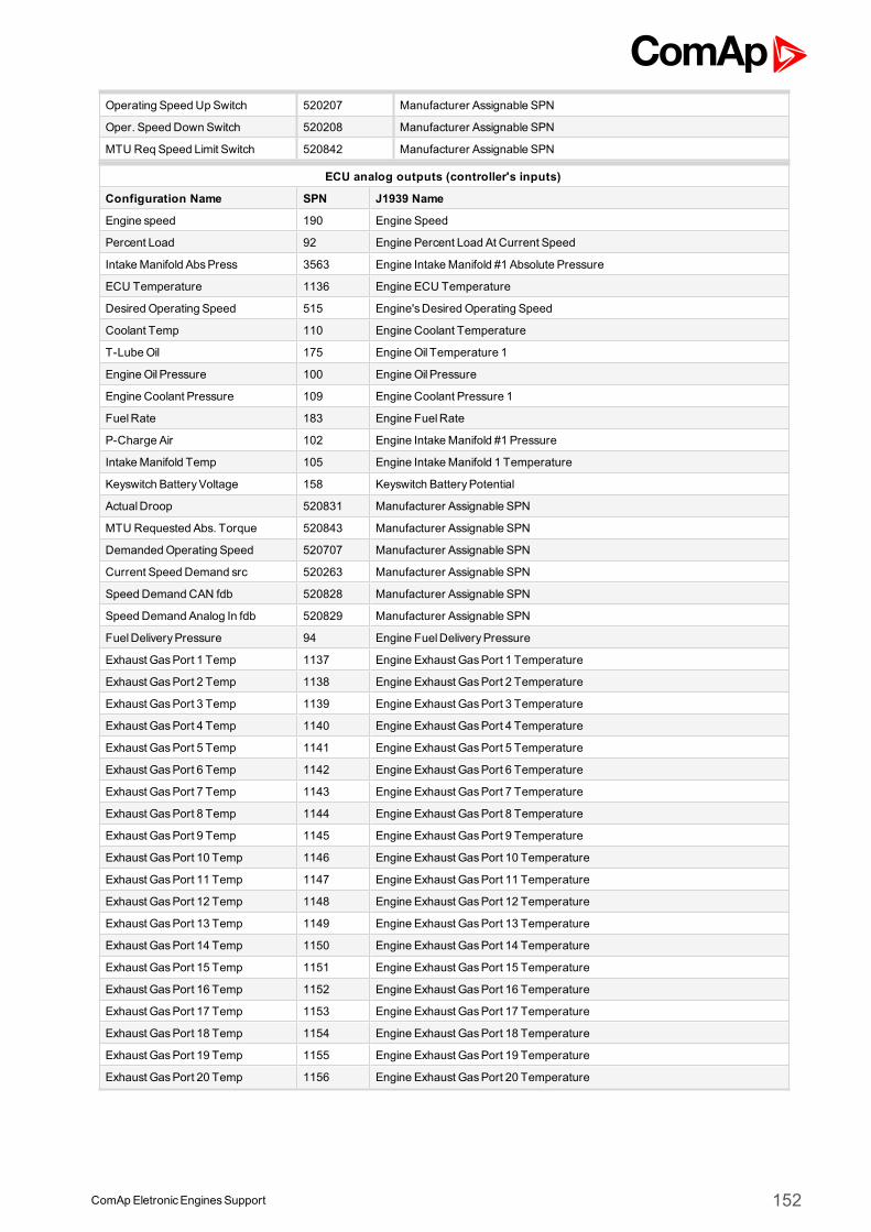
ComApEletronicEnginesSupport 152
Operating Speed Up Switch 520207 Manufacturer Assignable SPN
Oper. Speed Down Switch 520208 Manufacturer Assignable SPN
MTU Req Speed Limit Switch 520842 Manufacturer Assignable SPN
ECU analog outputs (controller's inputs)
Configuration Name SPN J1939 Name
Engine speed 190 Engine Speed
Percent Load 92 Engine Percent Load At Current Speed
IntakeManifold AbsPress 3563 Engine IntakeManifold #1 Absolute Pressure
ECU Temperature 1136 Engine ECU Temperature
Desired Operating Speed 515 Engine'sDesired Operating Speed
Coolant Temp 110 Engine Coolant Temperature
T-LubeOil 175 EngineOil Temperature 1
EngineOil Pressure 100 EngineOil Pressure
Engine Coolant Pressure 109 Engine Coolant Pressure 1
FuelRate 183 Engine FuelRate
P-Charge Air 102 Engine IntakeManifold #1 Pressure
IntakeManifold Temp 105 Engine IntakeManifold 1 Temperature
Keyswitch BatteryVoltage 158 Keyswitch BatteryPotential
ActualDroop 520831 Manufacturer Assignable SPN
MTU Requested Abs. Torque 520843 Manufacturer Assignable SPN
DemandedOperating Speed 520707 Manufacturer Assignable SPN
Current Speed Demand src 520263 Manufacturer Assignable SPN
Speed DemandCAN fdb 520828 Manufacturer Assignable SPN
Speed Demand Analog In fdb 520829 Manufacturer Assignable SPN
FuelDeliveryPressure 94 Engine FuelDeliveryPressure
Exhaust GasPort 1 Temp 1137 Engine Exhaust GasPort 1 Temperature
Exhaust GasPort 2 Temp 1138 Engine Exhaust GasPort 2 Temperature
Exhaust GasPort 3 Temp 1139 Engine Exhaust GasPort 3 Temperature
Exhaust GasPort 4 Temp 1140 Engine Exhaust GasPort 4 Temperature
Exhaust GasPort 5 Temp 1141 Engine Exhaust GasPort 5 Temperature
Exhaust GasPort 6 Temp 1142 Engine Exhaust GasPort 6 Temperature
Exhaust GasPort 7 Temp 1143 Engine Exhaust GasPort 7 Temperature
Exhaust GasPort 8 Temp 1144 Engine Exhaust GasPort 8 Temperature
Exhaust GasPort 9 Temp 1145 Engine Exhaust GasPort 9 Temperature
Exhaust GasPort 10 Temp 1146 Engine Exhaust GasPort 10 Temperature
Exhaust GasPort 11 Temp 1147 Engine Exhaust GasPort 11 Temperature
Exhaust GasPort 12 Temp 1148 Engine Exhaust GasPort 12 Temperature
Exhaust GasPort 13 Temp 1149 Engine Exhaust GasPort 13 Temperature
Exhaust GasPort 14 Temp 1150 Engine Exhaust GasPort 14 Temperature
Exhaust GasPort 15 Temp 1151 Engine Exhaust GasPort 15 Temperature
Exhaust GasPort 16 Temp 1152 Engine Exhaust GasPort 16 Temperature
Exhaust GasPort 17 Temp 1153 Engine Exhaust GasPort 17 Temperature
Exhaust GasPort 18 Temp 1154 Engine Exhaust GasPort 18 Temperature
Exhaust GasPort 19 Temp 1155 Engine Exhaust GasPort 19 Temperature
Exhaust GasPort 20 Temp 1156 Engine Exhaust GasPort 20 Temperature

ComApEletronicEnginesSupport 153
SeaWater PumpOutlet Pressure 2435 SeaWater PumpOutlet Pressure
P-LubeOilRedundant 520292 Manufacturer Assignable SPN
T-Coolant Redundant 520302 Manufacturer Assignable SPN
ECU analog inputs (controller's outputs)
Configuration Name SPN J1939 Name
Requested speed 1,2,3,4,5,6 898 Engine Requested Speed/Speed Limit
Speed Demand Switches5200269
Manufacturer Assignable SPNCAN Demand Switches contains at:Bit 0 - 3 the source for Local normal switch positionBit 4 - 7 the source for LocalEmergency switch positionBit 8 - 11 the source for Remote normal switch positionBit 12 - 15 the source for Remote Emergency switch position
With the following assignment per bit group:0 =Analog CAN1 =Up/Down ECU2 =Up/DownCAN3 =Analog ECU4 =Analog ECU relative5 =Frequency6 =Notch Position (not used)
FrequencySelection 1,2,3,4,5,6 4080
Generator FrequencySelectionThis feature gives the operator ability to switch the rated speed. The systemwillonly react to a state transition while the Engine speed is 0. The recommendedsource values is an contstant following the requested function.0 = 50Hz1 =60Hz2 - 5 =Reserved6 =Error7 =Do not care
Supported parameter by the controllers configured byNanoEdit, DriveEdit or LiteEdit PC software:
1 - InteliLiteNT, 2 - InteliLite , 3 - InteliDrive Lite , 4 - InteliCompactNT, 5 - InteliNanoNT, 6 - InteliDrive Nano
Controller’s analog output for speed control configurationRequested speed settings for InteliGenNT or InteliSysNT
Source SpeedReq RPM
Convert NO
LimitsN/A N/A
N/A N/A
Requested speed settings for InteliDrive DCU, InteliDrive Mobile
Source SpeedReq RPM
Convert NO
Limits0.0 % Min eng. speed (800RPM)
100.0 % Max eng. speed (2100RPM)
Smart module DIP switches adjustmentDIP 1 2 3 4 5 6 7 8
Function Speed DemandDroop(0%/4%)
Frequency(50Hz/60Hz)
Protocol(J1939/CanOpen)
N/A N/A
State ON OFF ON OFF OFF OFF OFF OFF
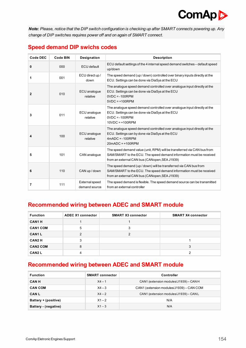
ComApEletronicEnginesSupport 154
Note: Please, notice that the DIP switch configuration is checking up after SMART connects powering up. Anychange of DIP switches requires power off and on again of SMART connect.
Speed demand DIP swichs codesCode DEC Code BIN Designation Description
0 000 ECU defaultECU default settingsof the 4 internal speed demand switches– default speedup/down
1 001ECU direct up /
downThe speed demand (up / down) controlled over binary inputs directly at theECU. Settings can be done via DiaSysat the ECU
2 010ECU analogue
relative
The analogue speed demand controlled over analogue input directly at theECU. Settings can be done via DiaSysat the ECU0VDC = -100RPM5VDC =+100RPM
3 011ECU analogue
relative
The analogue speed demand controlled over analogue input directly at theECU. Settings can be done via DiaSysat the ECU0VDC = -100RPM10VDC =+100RPM
4 100ECU analogue
relative
The analogue speed demand controlled over analogue input directly at theECU. Settings can bydone via DiaSysat the ECU4mADC = -100RPM20mADC =+100RPM
5 101 CAN analogueThe speed demand value (unit, RPM) will be transferred via CAN bus fromSAM/SMART to the ECU. The speed demand informationmust be receivedfrom an externalCAN bus (CANopen,SEA J1939)
6 110 CAN up / downThe speed demand (up / down) will be transferred via CAN bus fromSAM/SMART to the ECU. The speed demand informationmust be receivedfrom an externalCAN bus (CANopen,SEA J1939)
7 111External speeddemand source
The speed demand is flexible. The speed demand source can be transmittedfrom an external controller
Recommended wiring between ADEC and SMART moduleFunction ADEC X1 connector SMART X3 connector SMART X4 connector
CAN1 H 1 1
CAN1 COM 5 3
CAN1 L 2 2
CAN2 H 3 1
CAN2 COM 8 3
CAN2 L 4 2
Recommended wiring between ADEC and SMART moduleFunction SMART connector Controller
CAN H X4 – 1 CAN1 (extension modules/J1939) – CANH
CAN COM X4 – 3 CAN1 (extensionmodules/J1939) – CAN COM
CAN L X4 – 2 CAN1 (extension modules/J1939) – CANL
Battery + (positive) X1 – 2 N/A
Battery - (negative) X1 – 3 N/A
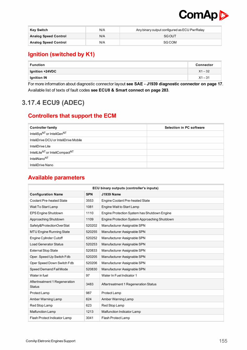
ComApEletronicEnginesSupport 155
Key Switch N/A Anybinary output configured asECU PwrRelay
Analog Speed Control N/A SGOUT
Analog Speed Control N/A SGCOM
Ignition (switched by K1)Function Connector
Ignition +24VDC X1 – 32
Ignition IN X1 – 31
Formore information about diagnostic connector layout see SAE - J1939 diagnostic connector on page 17.Available list of texts of fault codes see ECU8 & Smart connect on page 283.
3.17.4 ECU9 (ADEC)
Controllers that support the ECM
Controller family Selection in PC software
InteliSysNTor InteliGenNT
InteliDrive DCU or InteliDriveMobile
InteliDrive Lite
InteliLiteNTor InteliCompactNT
InteliNanoNT
InteliDrive Nano
Available parametersECU binary outputs (controller's inputs)
Configuration Name SPN J1939 Name
Coolant Pre-heated State 3553 Engine Coolant Pre-heated State
Wait To Start Lamp 1081 EngineWait to Start Lamp
EPSEngine Shutdown 1110 Engine Protection System hasShutdown Engine
Approaching Shutdown 1109 Engine Protection SystemApproaching Shutdown
Safety&ProtectionOverStat 520202 Manufacturer Assignable SPN
MTU Engine Running State 520255 Manufacturer Assignable SPN
Engine Cylinder Cutoff 520252 Manufacturer Assignable SPN
LoadGenerator Status 520253 Manufacturer Assignable SPN
ExternalStop State 520833 Manufacturer Assignable SPN
Oper. Speed Up Switch Fdb 520205 Manufacturer Assignable SPN
Oper Speed Down Switch Fdb 520206 Manufacturer Assignable SPN
Speed Demand FailMode 520830 Manufacturer Assignable SPN
Water in fuel 97 Water In Fuel Indicator 1
Aftertreatment 1 RegenerationStatus
3483 Aftertreatment 1 Regeneration Status
Protect Lamp 987 Protect Lamp
Amber Warning Lamp 624 Amber Warning Lamp
Red Stop Lamp 623 Red Stop Lamp
Malfunction Lamp 1213 Malfunction Indicator Lamp
Flash Protect Indicator Lamp 3041 Flash Protect Lamp
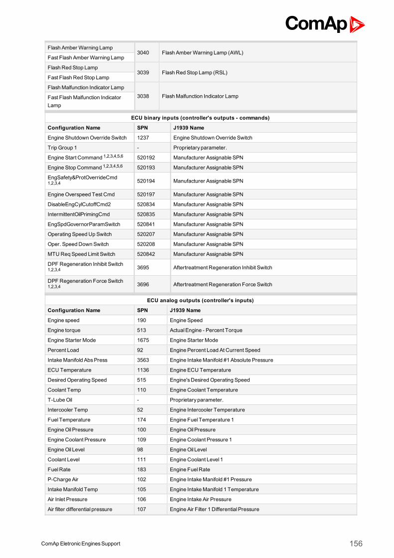
ComApEletronicEnginesSupport 156
Flash Amber Warning Lamp3040 Flash Amber Warning Lamp (AWL)
Fast Flash Amber Warning Lamp
Flash Red Stop Lamp3039 Flash Red Stop Lamp (RSL)
Fast Flash Red Stop Lamp
FlashMalfunction Indicator Lamp3038 FlashMalfunction Indicator LampFast FlashMalfunction Indicator
Lamp
ECU binary inputs (controller's outputs - commands)
Configuration Name SPN J1939 Name
Engine ShutdownOverride Switch 1237 Engine ShutdownOverride Switch
Trip Group 1 - Proprietary parameter.
Engine Start Command 1,2,3,4,5,6 520192 Manufacturer Assignable SPN
Engine Stop Command 1,2,3,4,5,6 520193 Manufacturer Assignable SPN
EngSafety&ProtOverrideCmd1,2,3,4 520194 Manufacturer Assignable SPN
EngineOverspeed Test Cmd 520197 Manufacturer Assignable SPN
DisableEngCylCutoffCmd2 520834 Manufacturer Assignable SPN
IntermittentOilPrimingCmd 520835 Manufacturer Assignable SPN
EngSpdGovernorParamSwitch 520841 Manufacturer Assignable SPN
Operating Speed Up Switch 520207 Manufacturer Assignable SPN
Oper. Speed Down Switch 520208 Manufacturer Assignable SPN
MTU Req Speed Limit Switch 520842 Manufacturer Assignable SPN
DPF Regeneration Inhibit Switch1,2,3,4 3695 Aftertreatment Regeneration Inhibit Switch
DPF Regeneration Force Switch1,2,3,4 3696 Aftertreatment Regeneration Force Switch
ECU analog outputs (controller's inputs)
Configuration Name SPN J1939 Name
Engine speed 190 Engine Speed
Engine torque 513 ActualEngine - Percent Torque
Engine Starter Mode 1675 Engine Starter Mode
Percent Load 92 Engine Percent Load At Current Speed
IntakeManifold AbsPress 3563 Engine IntakeManifold #1 Absolute Pressure
ECU Temperature 1136 Engine ECU Temperature
Desired Operating Speed 515 Engine'sDesired Operating Speed
Coolant Temp 110 Engine Coolant Temperature
T-LubeOil - Proprietary parameter.
Intercooler Temp 52 Engine Intercooler Temperature
Fuel Temperature 174 Engine Fuel Temperature 1
EngineOil Pressure 100 EngineOil Pressure
Engine Coolant Pressure 109 Engine Coolant Pressure 1
EngineOil Level 98 EngineOil Level
Coolant Level 111 Engine Coolant Level 1
FuelRate 183 Engine FuelRate
P-Charge Air 102 Engine IntakeManifold #1 Pressure
IntakeManifold Temp 105 Engine IntakeManifold 1 Temperature
Air Inlet Pressure 106 Engine Intake Air Pressure
Air filter differential pressure 107 Engine Air Filter 1 Differential Pressure
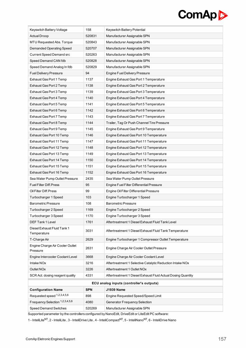
ComApEletronicEnginesSupport 157
Keyswitch BatteryVoltage 158 Keyswitch BatteryPotential
ActualDroop 520831 Manufacturer Assignable SPN
MTU Requested Abs. Torque 520843 Manufacturer Assignable SPN
DemandedOperating Speed 520707 Manufacturer Assignable SPN
Current Speed Demand src 520263 Manufacturer Assignable SPN
Speed DemandCAN fdb 520828 Manufacturer Assignable SPN
Speed Demand Analog In fdb 520829 Manufacturer Assignable SPN
FuelDeliveryPressure 94 Engine FuelDeliveryPressure
Exhaust GasPort 1 Temp 1137 Engine Exhaust GasPort 1 Temperature
Exhaust GasPort 2 Temp 1138 Engine Exhaust GasPort 2 Temperature
Exhaust GasPort 3 Temp 1139 Engine Exhaust GasPort 3 Temperature
Exhaust GasPort 4 Temp 1140 Engine Exhaust GasPort 4 Temperature
Exhaust GasPort 5 Temp 1141 Engine Exhaust GasPort 5 Temperature
Exhaust GasPort 6 Temp 1142 Engine Exhaust GasPort 6 Temperature
Exhaust GasPort 7 Temp 1143 Engine Exhaust GasPort 7 Temperature
Exhaust GasPort 8 Temp 1144 Trailer, TagOr Push Channel Tire Pressure
Exhaust GasPort 9 Temp 1145 Engine Exhaust GasPort 9 Temperature
Exhaust GasPort 10 Temp 1146 Engine Exhaust GasPort 10 Temperature
Exhaust GasPort 11 Temp 1147 Engine Exhaust GasPort 11 Temperature
Exhaust GasPort 12 Temp 1148 Engine Exhaust GasPort 12 Temperature
Exhaust GasPort 13 Temp 1149 Engine Exhaust GasPort 13 Temperature
Exhaust GasPort 14 Temp 1150 Engine Exhaust GasPort 14 Temperature
Exhaust GasPort 15 Temp 1151 Engine Exhaust GasPort 15 Temperature
Exhaust GasPort 16 Temp 1152 Engine Exhaust GasPort 16 Temperature
SeaWater PumpOutlet Pressure 2435 SeaWater PumpOutlet Pressure
Fuel Filter Diff.Press 95 Engine Fuel Filter Differential Pressure
Oil Filter Diff.Press 99 EngineOil Filter Differential Pressure
Turbocharger 1 Speed 103 Engine Turbocharger 1 Speed
BarometricPressure 108 BarometricPressure
Turbocharger 2 Speed 1169 Engine Turbocharger 2 Speed
Turbocharger 3 Speed 1170 Engine Turbocharger 3 Speed
DEF Tank1 Level 1761 Aftertreatment 1 DieselExhaust Fluid TankLevel
DieselExhaust Fluid Tank1Temperature
3031 Aftertreatment 1 DieselExhaust Fluid TankTemperature
T-Charge Air 2629 Engine Turbocharger 1 Compressor Outlet Temperature
Engine Charge Air Cooler OutletPressure
2631 Engine Charge Air Cooler Outlet Pressure
Engine Intercooler Coolant Level 3668 Engine Charge Air Cooler Coolant Level
Intake NOx 3216 Aftertreatment 1 Selective CatalyticReduction Intake NOx
Outlet NOx 3226 Aftertreatment 1 Outlet NOx
SCR Act. dosing reagent quality 4331 Aftertreatment 1 DieselExhaust Fluid ActualDosingQuantity
ECU analog inputs (controller's outputs)
Configuration Name SPN J1939 Name
Requested speed 1,2,3,4,5,6 898 Engine Requested Speed/Speed Limit
FrequencySelection 1,2,3,4,5,6 4080 Generator FrequencySelection
Speed Demand Switches 520269 Manufacturer Assignable SPN
Supported parameter by the controllers configured byNanoEdit, DriveEdit or LiteEdit PC software:
1 - InteliLiteNT, 2 - InteliLite , 3 - InteliDrive Lite , 4 - InteliCompactNT, 5 - InteliNanoNT, 6 - InteliDrive Nano
ComApEletronicEnginesSupport 158
Controller’s analog output for speed control configurationRequested speed settings for InteliGenNT or InteliSysNT
Source SpeedReq RPM
Convert NO
LimitsN/A N/A
N/A N/A
Requested speed settings for InteliDrive DCU, InteliDrive Mobile
Source SpeedReq RPM
Convert NO
Limits0.0 % Min eng. speed (800RPM)
100.0 % Max eng. speed (2100RPM)
Recommended wiringFunction ECU connector Controller
CAN H CAN1 (extension modules/J1939) – CANH
CAN COM CAN1 (extensionmodules/J1939) – CAN COM
CAN L CAN1 (extension modules/J1939) – CANL
Battery + (positive) N/A
Battery - (negative) N/A
Key Switch Anybinary output configured asECU PwrRelay
Analog Speed Control SGOUT
Analog Speed Control SGCOM
Formore information about diagnostic connector layout see SAE - J1939 diagnostic connector on page 17.Available list of texts of fault codes see ECU9 on page 285.
3.17.5 ECU4 (MDEC)Note: For connection toMTU MDEC module it is necessary to use an I-CB module. Configuration of thecontroller and I-CB has to be done separately using GenConfig or DriveConfig and ICBEdit software. Forfurther information see I-CB manual.
Controllers that support the ECU4
Selection in PC software
InteliSysNT or InteliGenNT I-CB/MTU-Diesel
InteliDrive DCU or InteliDrive Mobile I-CB/MTU-Diesel
InteliDrive Lite not supported
InteliLiteNT or InteliCompactNT not supported
InteliLite not supported
InteliNanoNT not supported
InteliDrive Nano not supported
Available parametersFormore information about available values and signals, please refer to I-CB manual or ICBEdit PC software.
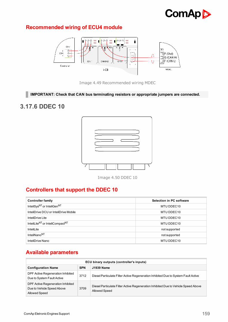
ComApEletronicEnginesSupport 159
Recommended wiring of ECU4 module
Image 4.49 Recommended wiring MDEC
IMPORTANT: Check that CAN bus terminating resistors or appropriate jumpers are connected.
3.17.6 DDEC 10
Image 4.50 DDEC 10
Controllers that support the DDEC 10
Controller family Selection in PC software
InteliSysNTor InteliGenNT MTUDDEC10
InteliDrive DCU or InteliDriveMobile MTU DDEC10
InteliDrive Lite MTU DDEC10
InteliLiteNTor InteliCompactNT MTUDDEC10
InteliLite not supported
InteliNanoNT not supported
InteliDrive Nano MTU DDEC10
Available parametersECU binary outputs (controller's inputs)
Configuration Name SPN J1939 Name
DPF Active Regeneration InhibitedDue to System Fault Active
3712 DieselParticulate Filter Active Regeneration Inhibited Due to System Fault Active
DPF Active Regeneration InhibitedDue to Vehicle Speed AboveAllowed Speed
3709DieselParticulate Filter Active Regeneration Inhibited Due to Vehicle Speed AboveAllowed Speed
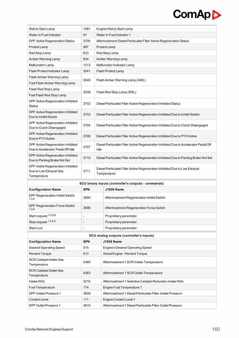
ComApEletronicEnginesSupport 160
Wait to Start Lamp 1081 EngineWait to Start Lamp
Water In Fuel Indicator 97 Water In Fuel Indicator 1
DPF Active Regeneration Status 3700 Aftertreatment DieselParticulate Filter Active Regeneration Status
Protect Lamp 987 Protect Lamp
Red Stop Lamp 623 Red Stop Lamp
Amber Warning Lamp 624 Amber Warning Lamp
Malfunction Lamp 1213 Malfunction Indicator Lamp
Flash Protect Indicator Lamp 3041 Flash Protect Lamp
Flash Amber Warning Lamp3040 Flash Amber Warning Lamp (AWL)
Fast Flash Amber Warning Lamp
Flash Red Stop Lamp3039 Flash Red Stop Lamp (RSL)
Fast Flash Red Stop Lamp
DPF Active Regeneration InhibitedStatus
3702 DieselParticulate Filter Active Regeneration Inhibited Status
DPF Active Regeneration InhibitedDue to Inhibit Switch
3703 DieselParticulate Filter Active Regeneration Inhibited Due to Inhibit Switch
DPF Active Regeneration InhibitedDue to Clutch Disengaged
3704 DieselParticulate Filter Active Regeneration Inhibited Due to Clutch Disengaged
DPF Active Regeneration InhibitedDue to PTOActive
3706 DieselParticulate Filter Active Regeneration Inhibited Due to PTOActive
DPF Active Regeneration InhibitedDue to Accelerator PedalOff Idle
3707DieselParticulate Filter Active Regeneration Inhibited Due to Accelerator PedalOffIdle
DPF Active Regeneration InhibitedDue to Parking Brake Not Set
3710 DieselParticulate Filter Active Regeneration Inhibited Due to Parking Brake Not Set
DPF Active Regeneration InhibitedDue to Low Exhaust GasTemperature
3711DieselParticulate Filter Active Regeneration Inhibited Due to Low ExhaustTemperature
ECU binary inputs (controller's outputs - commands)
Configuration Name SPN J1939 Name
DPF Regeneration Inhibit Switch1,3,4 3695 Aftertreatment Regeneration Inhibit Switch
DPF Regeneration Force Switch1,3,4 3696 Aftertreatment Regeneration Force Switch
Start request 1,3,4,6 - Proprietary parameter.
Stop request 1,3,4,6 - Proprietary parameter.
Start Loct - Proprietary parameter.
ECU analog outputs (controller's inputs)
Configuration Name SPN J1939 Name
Desired Operating Speed 515 Engine'sDesired Operating Speed
Percent Torque 513 ActualEngine - Percent Torque
SCR Catalyst IntakeGasTemperature
4360 Aftertreatment 1 SCR Intake Temperature
SCR Catalyst Outlet GasTemperature
4363 Aftertreatment 1 SCROutlet Temperature
Intake NOx 3216 Aftertreatment 1 Selective CatalyticReduction Intake NOx
Fuel Temperature 174 Engine Fuel Temperature 1
DPF Intake Pressure 1 3609 Aftertreatment 1 DieselParticulate Filter Intake Pressure
Coolant Level 111 Engine Coolant Level 1
DPF Outlet Pressure 1 3610 Aftertreatment 1 DieselParticulate Filter Outlet Pressure
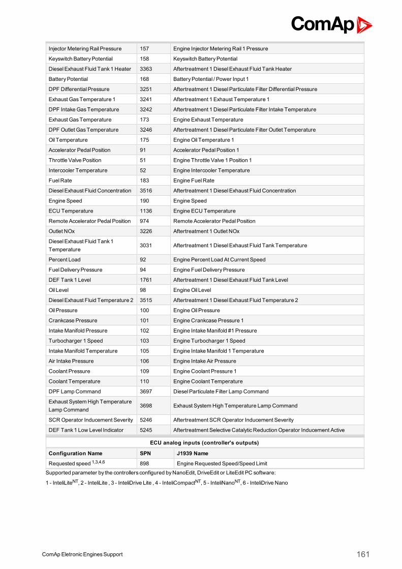
ComApEletronicEnginesSupport 161
Injector Metering Rail Pressure 157 Engine Injector Metering Rail 1 Pressure
Keyswitch BatteryPotential 158 Keyswitch BatteryPotential
DieselExhaust Fluid Tank1 Heater 3363 Aftertreatment 1 DieselExhaust Fluid TankHeater
BatteryPotential 168 BatteryPotential / Power Input 1
DPF Differential Pressure 3251 Aftertreatment 1 DieselParticulate Filter Differential Pressure
Exhaust GasTemperature 1 3241 Aftertreatment 1 Exhaust Temperature 1
DPF IntakeGasTemperature 3242 Aftertreatment 1 DieselParticulate Filter Intake Temperature
Exhaust GasTemperature 173 Engine Exhaust Temperature
DPF Outlet GasTemperature 3246 Aftertreatment 1 DieselParticulate Filter Outlet Temperature
Oil Temperature 175 EngineOil Temperature 1
Accelerator PedalPosition 91 Accelerator PedalPosition 1
Throttle Valve Position 51 Engine Throttle Valve 1 Position 1
Intercooler Temperature 52 Engine Intercooler Temperature
FuelRate 183 Engine FuelRate
DieselExhaust Fluid Concentration 3516 Aftertreatment 1 DieselExhaust Fluid Concentration
Engine Speed 190 Engine Speed
ECU Temperature 1136 Engine ECU Temperature
Remote Accelerator PedalPosition 974 Remote Accelerator PedalPosition
Outlet NOx 3226 Aftertreatment 1 Outlet NOx
DieselExhaust Fluid Tank1Temperature
3031 Aftertreatment 1 DieselExhaust Fluid TankTemperature
Percent Load 92 Engine Percent Load At Current Speed
FuelDeliveryPressure 94 Engine FuelDeliveryPressure
DEF Tank1 Level 1761 Aftertreatment 1 DieselExhaust Fluid TankLevel
Oil Level 98 EngineOil Level
DieselExhaust Fluid Temperature 2 3515 Aftertreatment 1 DieselExhaust Fluid Temperature 2
Oil Pressure 100 EngineOil Pressure
Crankcase Pressure 101 Engine Crankcase Pressure 1
IntakeManifold Pressure 102 Engine IntakeManifold #1 Pressure
Turbocharger 1 Speed 103 Engine Turbocharger 1 Speed
IntakeManifold Temperature 105 Engine IntakeManifold 1 Temperature
Air Intake Pressure 106 Engine Intake Air Pressure
Coolant Pressure 109 Engine Coolant Pressure 1
Coolant Temperature 110 Engine Coolant Temperature
DPF LampCommand 3697 DieselParticulate Filter LampCommand
Exhaust SystemHigh TemperatureLampCommand
3698 Exhaust SystemHigh Temperature LampCommand
SCROperator Inducement Severity 5246 Aftertreatment SCROperator Inducement Severity
DEF Tank1 Low Level Indicator 5245 Aftertreatment Selective CatalyticReduction Operator Inducement Active
ECU analog inputs (controller's outputs)
Configuration Name SPN J1939 Name
Requested speed 1,3,4,6 898 Engine Requested Speed/Speed Limit
Supported parameter by the controllers configured byNanoEdit, DriveEdit or LiteEdit PC software:
1 - InteliLiteNT, 2 - InteliLite , 3 - InteliDrive Lite , 4 - InteliCompactNT, 5 - InteliNanoNT, 6 - InteliDrive Nano
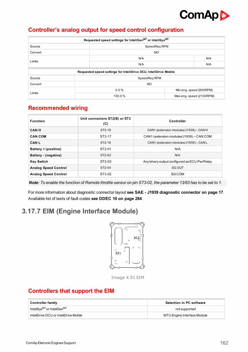
ComApEletronicEnginesSupport 162
Controller’s analog output for speed control configurationRequested speed settings for InteliGenNT or InteliSysNT
Source SpeedReq RPM
Convert NO
LimitsN/A N/A
N/A N/A
Requested speed settings for InteliDrive DCU, InteliDrive Mobile
Source SpeedReq RPM
Convert NO
Limits0.0 % Min eng. speed (800RPM)
100.0 % Max eng. speed (2100RPM)
Recommended wiring
FunctionUnit connectors ST2(B) or ST3
(C)Controller
CAN H ST2-18 CAN1 (extension modules/J1939) – CANH
CAN COM ST2-17 CAN1 (extensionmodules/J1939) – CAN COM
CAN L ST2-16 CAN1 (extension modules/J1939) – CANL
Battery + (positive) ST2-01 N/A
Battery - (negative) ST2-02 N/A
Key Switch ST2-03 Anybinary output configured asECU PwrRelay
Analog Speed Control ST2-04 SG OUT
Analog Speed Control ST3-02 SGCOM
Note: To enable the function of Remote throttle sensor on pin ST3-02, the parameter 13/63 has to be set to 1.
Formore information about diagnostic connector layout see SAE - J1939 diagnostic connector on page 17.Available list of texts of fault codes see DDEC 10 on page 284.
3.17.7 EIM (Engine Interface Module)
Image 4.51 EIM
Controllers that support the EIM
Controller family Selection in PC software
InteliSysNTor InteliGenNT not supported
InteliDrive DCU or InteliDriveMobile MTU Engine InterfaceModule
ComApEletronicEnginesSupport 163
InteliDrive Lite MTU Engine InterfaceModule
InteliLiteNTor InteliCompactNT not supported
InteliLite not supported
InteliNanoNT not supported
InteliDrive Nano MTU Engine InterfaceModule
Available parametersECU binary outputs (controller's inputs)
Configuration Name SPN J1939 Name
Amber Warning Lamp 624 Amber Warning Lamp
Red Stop Lamp 623 Red Stop Lamp
ECU binary outputs (controller's inputs)
Configuration Name SPN J1939 Name
ECU binary outputs (controller's inputs)
Configuration Name SPN J1939 Name
Percent Load 92 Engine Percent Load At Current Speed
Engine speed 190 Engine Speed
Engine Exhaust GasTempAvg 1
4151 Engine Exhaust Temperature Average
IntakeManifold AbsPress 3563 Engine IntakeManifold #1 Absolute Pressure
Exhaust GasTemp - RightManifold
2433 Engine Exhaust Manifold Bank2 Temperature 1
Exhaust GasTemp - LeftManifold
2434 Engine Exhaust Manifold Bank1 Temperature 1
Coolant Temp 110 Engine Coolant Temperature
Fuel Temp 174 Engine Fuel Temperature 1
EngineOil Temp 175 EngineOil Temperature 1
FuelDeliveryPressure 94 Engine FuelDeliveryPressure
EngineOil Pressure 100 EngineOil Pressure
Coolant Pressure 109 Engine Coolant Pressure 1
FuelRate 183 Engine FuelRate
Air Inlet Temperature 172 Engine Intake Air Temperature
IntakeManifold Temp 105 Engine IntakeManifold 1 Temperature
MTU Engine SpeedRedundant
520382 Manufacturer Assignable SPN
MTU EngineOil PressureRedundant
520292 Manufacturer Assignable SPN
MTU Engine Coolant TempRedundant
520302 Manufacturer Assignable SPN
ECU binary outputs (controller's inputs)
Configuration Name SPN J1939 NameSupported parameter by the controllers configured byNanoEdit, DriveEdit or LiteEdit PC software:
1 - InteliLiteNT, 2 - InteliLite , 3 - InteliDrive Lite , 4 - InteliCompactNT, 5 - InteliNanoNT, 6 - InteliDrive Nano
ComApEletronicEnginesSupport 164
Recommended wiringFunction X51 connector Controller
CAN H 56 CAN1 (extensionmodules/J1939) – CAN H
CAN COM 54 CAN1 (extensionmodules/J1939) – CAN COM
CAN L 55 CAN1 (extensionmodules/J1939) – CAN L
Battery + (positive) N/A N/A
Battery - (negative) N/A N/A
Key Switch 16 Anybinary output configured asECU PwrRelay
Analog Speed Control N/A SGOUT
Analog Speed Control N/A SGCOM
Formore information about diagnostic connector layout see SAE - J1939 diagnostic connector on page 17.Available list of texts of fault codes see EIM on page 287.
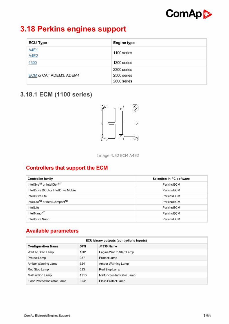
ComApEletronicEnginesSupport 165
3.18 Perkins engines supportECU Type Engine type
A4E1A4E2
1100 series
1300 1300 series
ECM or CAT ADEM3, ADEM42300 series2500 series2800 series
3.18.1 ECM (1100 series)
Image 4.52 ECM A4E2
Controllers that support the ECM
Controller family Selection in PC software
InteliSysNTor InteliGenNT PerkinsECM
InteliDrive DCU or InteliDriveMobile PerkinsECM
InteliDrive Lite PerkinsECM
InteliLiteNTor InteliCompactNT PerkinsECM
InteliLite PerkinsECM
InteliNanoNT PerkinsECM
InteliDrive Nano PerkinsECM
Available parametersECU binary outputs (controller's inputs)
Configuration Name SPN J1939 Name
Wait To Start Lamp 1081 EngineWait to Start Lamp
Protect Lamp 987 Protect Lamp
Amber Warning Lamp 624 Amber Warning Lamp
Red Stop Lamp 623 Red Stop Lamp
Malfunction Lamp 1213 Malfunction Indicator Lamp
Flash Protect Indicator Lamp 3041 Flash Protect Lamp
ComApEletronicEnginesSupport 166
Flash Amber Warning Lamp3040 Flash Amber Warning Lamp (AWL)
Fast Flash Amber Warning Lamp
Flash Red Stop Lamp3039 Flash Red Stop Lamp (RSL)
Fast Flash Red Stop Lamp
ECU binary inputs (controller's outputs - commands)
Configuration Name SPN J1939 Name
Stop Request 1,2,3,4,5,6 -Proprietary parameter.The command for normal stopping of the engine. The recommended source value forthis command is stop pulse.
AlarmReset 4 - Proprietary parameter.
Engine Start 4 - Proprietary parameter.
Override - Proprietary parameter.
Engine alternate droop accelerator1 select 4
- Proprietary parameter.
ECU analog outputs (controller's inputs)
Configuration Name SPN J1939 Name
Engine speed 190 Engine Speed
Percent Load 92 Engine Percent Load At Current Speed
Coolant Temp 110 Engine Coolant Temperature
Fuel Temp 174 Engine Fuel Temperature 1
EngineOil Temp 175 EngineOil Temperature 1
Boost Pressure 102 Engine IntakeManifold #1 Pressure
IntakeManifold Temp 105 Engine IntakeManifold 1 Temperature
Desired Operating Speed 515 Engine'sDesired Operating Speed
BarometricPressure 108 BarometricPressure
FuelRate 183 Engine FuelRate
Throttle position 51 Engine Throttle Valve 1 Position 1
ElectricalPotential (Voltage) 168 BatteryPotential / Power Input 1
BatteryPotential (Voltage) 158 Keyswitch BatteryPotential
EngineOil Pressure 100 EngineOil Pressure
ECU analog inputs (controller's outputs)
Configuration Name SPN J1939 Name
Requested speed 1,2,3,4,5,6 898 Engine Requested Speed/Speed Limit
Supported parameter by the controllers configured byNanoEdit, DriveEdit or LiteEdit PC software:
1 - InteliLiteNT, 2 - InteliLite , 3 - InteliDrive Lite , 4 - InteliCompactNT, 5 - InteliNanoNT, 6 - InteliDrive Nano
Controller’s analog output for speed control configurationRequested speed settings for InteliGenNT or InteliSysNT
Source SpeedReq RPM
Convert NO
LimitsN/A N/A
N/A N/A
Requested speed settings for InteliDrive DCU, InteliDrive Mobile
Source SpeedReq RPM
Convert NO
Limits0.0 % Min eng. speed (800RPM)
100.0 % Max eng. speed (2100RPM)
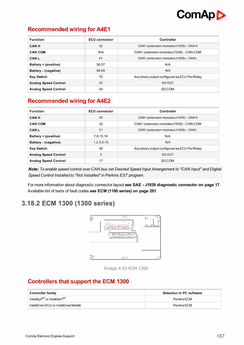
ComApEletronicEnginesSupport 167
Recommended wiring for A4E1Function ECU connector Controller
CAN H 52 CAN1 (extension modules/J1939) – CANH
CAN COM N/A CAN1 (extensionmodules/J1939) – CAN COM
CAN L 61 CAN1 (extension modules/J1939) – CANL
Battery + (positive) 56,57 N/A
Battery - (negative) 68,69 N/A
Key Switch 70 Anybinary output configured asECU PwrRelay
Analog Speed Control 25 SG OUT
Analog Speed Control 44 SGCOM
Recommended wiring for A4E2Function ECU connector Controller
CAN H 20 CAN1 (extension modules/J1939) – CANH
CAN COM 22 CAN1 (extensionmodules/J1939) – CAN COM
CAN L 21 CAN1 (extension modules/J1939) – CANL
Battery + (positive) 7,8,15,16 N/A
Battery - (negative) 1,2,3,9,10 N/A
Key Switch 40 Anybinary output configured asECU PwrRelay
Analog Speed Control 3 SG OUT
Analog Speed Control 17 SGCOM
Note: To enable speed control over CAN bus set Desired Speed Input Arrangement to "CAN Input" and DigitalSpeed Control Installed to "Not Installed" in Perkins EST program.
Formore information about diagnostic connector layout see SAE - J1939 diagnostic connector on page 17.Available list of texts of fault codes see ECM (1100 series) on page 291.
3.18.2 ECM 1300 (1300 series)
Image 4.53 ECM 1300
Controllers that support the ECM 1300
Controller family Selection in PC software
InteliSysNTor InteliGenNT PerkinsECM
InteliDrive DCU or InteliDriveMobile PerkinsECM
ComApEletronicEnginesSupport 168
InteliDrive Lite PerkinsECM
InteliLiteNTor InteliCompactNTPerkinsECM
orPerkins 1300 (without speed control)
InteliLitePerkinsECM
orPerkins 1300 (without speed control)
InteliNanoNTPerkinsECM
orPerkins 1300 (without speed control)
InteliDrive Nano PerkinsECM
Available parameters for ECMECU binary outputs (controller's inputs)
Configuration Name SPN J1939 Name
Wait To Start Lamp 1081 EngineWait to Start Lamp
Protect Lamp 987 Protect Lamp
Amber Warning Lamp 624 Amber Warning Lamp
Red Stop Lamp 623 Red Stop Lamp
Malfunction Lamp 1213 Malfunction Indicator Lamp
Flash Protect Indicator Lamp 3041 Flash Protect Lamp
Flash Amber Warning Lamp
3040 Flash Amber Warning Lamp (AWL)Fast Flash Amber WarningLamp
Flash Red Stop Lamp3039 Flash Red Stop Lamp (RSL)
Fast Flash Red Stop Lamp
ECU binary outputs (controller's inputs)
Configuration Name SPN J1939 Name
Stop Request 1,2,3,4,5,6 -Proprietary parameter.The command for normal stopping of the engine. The recommended sourcevalue for this command is stop pulse.
AlarmReset 4 - Proprietary parameter.
Engine Start 4 - Proprietary parameter.
Override - Proprietary parameter.
Engine alternate droopaccelerator 1 select 4
- Proprietary parameter.
ECU binary outputs (controller's inputs)
Configuration Name SPN J1939 Name
Engine speed 190 Engine Speed
Percent Load 92 Engine Percent Load At Current Speed
Coolant Temp 110 Engine Coolant Temperature
Fuel Temp 174 Engine Fuel Temperature 1
EngineOil Temp 175 EngineOil Temperature 1
Boost Pressure 102 Engine IntakeManifold #1 Pressure
IntakeManifold Temp 105 Engine IntakeManifold 1 Temperature
Desired Operating Speed 515 Engine'sDesired Operating Speed
BarometricPressure 108 BarometricPressure
FuelRate 183 Engine FuelRate
ComApEletronicEnginesSupport 169
Throttle position 51 Engine Throttle Valve 1 Position 1
ElectricalPotential (Voltage) 168 BatteryPotential / Power Input 1
BatteryPotential (Voltage) 158 Keyswitch BatteryPotential
EngineOil Pressure 100 EngineOil Pressure
ECU binary outputs (controller's inputs)
Configuration Name SPN J1939 Name
Requested speed 1,2,3,4,5,6 898 Engine Requested Speed/Speed Limit
Supported parameter by the controllers configured byNanoEdit, DriveEdit or LiteEdit PC software:
1 - InteliLiteNT, 2 - InteliLite , 3 - InteliDrive Lite , 4 - InteliCompactNT, 5 - InteliNanoNT, 6 - InteliDrive Nano
Available parameters for ECM 1300ECU binary outputs (controller's inputs)
Configuration Name SPN J1939 Name
Wait To Start Lamp 1081 EngineWait to Start Lamp
Protect Lamp 987 Protect Lamp
Amber Warning Lamp 624 Amber Warning Lamp
Red Stop Lamp 623 Red Stop Lamp
Malfunction Lamp 1213 Malfunction Indicator Lamp
ECU binary inputs (controller's outputs - commands)
Configuration Name SPN J1939 Name
Stop Request -Proprietary parameter.The command for normal stopping of the engine. The recommended source value forthis command is stop pulse.
ECU analog outputs (controller's inputs)
Configuration Name SPN J1939 Name
Engine speed 190 Engine Speed
Percent Load 92 Engine Percent Load At Current Speed
Coolant Temp 110 Engine Coolant Temperature
Fuel Temp 174 Engine Fuel Temperature 1
EngineOil Temp 175 EngineOil Temperature 1
Boost Pressure 102 Engine IntakeManifold #1 Pressure
IntakeManifold Temp 105 Engine IntakeManifold 1 Temperature
Desired Operating Speed 515 Engine'sDesired Operating Speed
BarometricPressure 108 BarometricPressure
FuelRate 183 Engine FuelRate
Throttle position 51 Engine Throttle Valve 1 Position 1
ElectricalPotential (Voltage) 168 BatteryPotential / Power Input 1
BatteryPotential (Voltage) 158 Keyswitch BatteryPotential
EngineOil Pressure 100 EngineOil Pressure
ECU analog inputs (controller's outputs)
Configuration Name SPN J1939 Name
ComApEletronicEnginesSupport 170
Recommended wiring for ECM 1300Function ECU connector Controller
CAN H 19 CAN1 (extension modules/J1939) – CANH
CAN COM 18 CAN1 (extensionmodules/J1939) – CAN COM
CAN L 20 CAN1 (extension modules/J1939) – CANL
Battery + (positive) 25,21,22,41 N/A
Battery - (negative) 23,42,1,2 N/A
Key Switch 24 Anybinary output configured asECU PwrRelay
Analog Speed Control 30 SG OUT
Analog Speed Control 11 SGCOM
Recommended wiring for CAT unitFunction ECU J1 21pin connector Controller
CAN H 20 CAN1 (extension modules/J1939) – CANH
CAN COM 22 CAN1 (extensionmodules/J1939) – CAN COM
CAN L 21 CAN1 (extension modules/J1939) – CANL
Battery + (positive) 7,8,15,16 N/A
Battery - (negative) 1,2,3,9,10 N/A
Key Switch 40 Anybinary output configured asECU PwrRelay
Analog Speed Control 3 SG OUT
Analog Speed Control 17 SGCOM
Formore information about diagnostic connector layout see SAE - J1939 diagnostic connector on page 17.Available list of texts of fault codes see ECM (1100 series) on page 291.
Available list of texts of fault codes see ECM 1300 (1300 series) on page 292.
Note: To enable speed control over CAN bus if possible - set Desired Speed Input Arrangement to "CAN Input"and Digital Speed Control Installed to "Not Installed" in Perkins EST program.
IMPORTANT: No value for speed control being sent to the ECU when Perkins 1300 is configured!
Note: To enable speed control over CAN bus set Desired Speed Input Arrangement to "CAN Input" and DigitalSpeed Control Installed to "Not Installed" in Perkins EST program.
3.18.3 ADEM (2300, 2500, 2800 series)
Image 4.54 ADEM3
ComApEletronicEnginesSupport 171
Controllers that support the ADEM
Controller family Selection in PC software
InteliSysNTor InteliGenNT PerkinsECM
InteliDrive DCU or InteliDriveMobile PerkinsECM
InteliDrive Lite PerkinsECM
InteliLiteNTor InteliCompactNT PerkinsECM
InteliLite PerkinsECM
InteliNanoNT PerkinsECM
InteliDrive Nano PerkinsECM
Available parametersECU binary outputs (controller's inputs)
Configuration Name SPN J1939 Name
Wait To Start Lamp 1081 EngineWait to Start Lamp
Protect Lamp 987 Protect Lamp
Amber Warning Lamp 624 Amber Warning Lamp
Red Stop Lamp 623 Red Stop Lamp
Malfunction Lamp 1213 Malfunction Indicator Lamp
Flash Protect Indicator Lamp 3041 Flash Protect Lamp
Flash Amber Warning Lamp
3040 Flash Amber Warning Lamp (AWL)Fast Flash Amber WarningLamp
Flash Red Stop Lamp3039 Flash Red Stop Lamp (RSL)
Fast Flash Red Stop Lamp
ECU binary outputs (controller's inputs)
Configuration Name SPN J1939 Name
Stop Request 1,2,3,4,5,6 -Proprietary parameter.The command for normal stopping of the engine. The recommended sourcevalue for this command is stop pulse.
AlarmReset 4 - Proprietary parameter.
Engine Start 4 - Proprietary parameter.
Override - Proprietary parameter.
Engine alternate droopaccelerator 1 select 4
- Proprietary parameter.
ECU binary outputs (controller's inputs)
Configuration Name SPN J1939 Name
Engine speed 190 Engine Speed
Percent Load 92 Engine Percent Load At Current Speed
Coolant Temp 110 Engine Coolant Temperature
Fuel Temp 174 Engine Fuel Temperature 1
EngineOil Temp 175 EngineOil Temperature 1
Boost Pressure 102 Engine IntakeManifold #1 Pressure
IntakeManifold Temp 105 Engine IntakeManifold 1 Temperature
Desired Operating Speed 515 Engine'sDesired Operating Speed
BarometricPressure 108 BarometricPressure
FuelRate 183 Engine FuelRate
ComApEletronicEnginesSupport 172
Throttle position 51 Engine Throttle Valve 1 Position 1
ElectricalPotential (Voltage) 168 BatteryPotential / Power Input 1
BatteryPotential (Voltage) 158 Keyswitch BatteryPotential
EngineOil Pressure 100 EngineOil Pressure
ECU binary outputs (controller's inputs)
Configuration Name SPN J1939 Name
Requested speed 1,2,3,4,5,6 898 Engine Requested Speed/Speed Limit
Supported parameter by the controllers configured byNanoEdit, DriveEdit or LiteEdit PC software:
1 - InteliLiteNT, 2 - InteliLite , 3 - InteliDrive Lite , 4 - InteliCompactNT, 5 - InteliNanoNT, 6 - InteliDrive Nano
Controller’s analog output for speed control configurationRequested speed settings for InteliGenNT or InteliSysNT
Source SpeedReq RPM
Convert NO
LimitsN/A N/A
N/A N/A
Requested speed settings for InteliDrive DCU, InteliDrive Mobile
Source SpeedReq RPM
Convert NO
Limits0.0 % Min eng. speed (800RPM)
100.0 % Max eng. speed (2100RPM)
Recommended wiring for ADEM4 (2200, 2500 series)Function ECU J1 connector Controller
CAN H 50 CAN1 (extension modules/J1939) – CANH
CAN COM 42 CAN1 (extensionmodules/J1939) – CAN COM
CAN L 34 CAN1 (extension modules/J1939) – CANL
Battery + (positive) 48,52,53,70 N/A
Battery - (negative) 61,63,65 N/A
Key Switch N/A Anybinary output configured asECU PwrRelay
Analog Speed Control N/A SGOUT
Analog Speed Control N/A SGCOM
Recommended wiring for ADEM3 (2300, 2800 series)Function ECU J1 connector Controller
CAN H 50 CAN1 (extension modules/J1939) – CANH
CAN COM 42 CAN1 (extensionmodules/J1939) – CAN COM
CAN L 34 CAN1 (extension modules/J1939) – CANL
Battery + (positive) 48,52,53,70 N/A
Battery - (negative) 61,63,65 N/A
Key Switch N/A Anybinary output configured asECU PwrRelay
Analog Speed Control 17 SGOUT
Analog Speed Control 3 SGCOM
Formore information about diagnostic connector layout see SAE - J1939 diagnostic connector on page 17.Available list of texts of fault codes see ADEM (2300, 2500, 2800 series) on page 293.
ComApEletronicEnginesSupport 173
Note: To enable speed control over CAN bus set Desired Speed Input Arrangement to "CAN Input" and DigitalSpeed Control Installed to "Not Installed" in Perkins EST program. Ormake a loop on J1 connector pins 49 and18.
ComApEletronicEnginesSupport 174
3.19 Scania engines supportECU Type Engine type
S6 SinglespeedS6 Allspeed
DC9DI12DC12DC16D9MDI12MDI16M
S8 SinglespeedS8 Allspeed
DC9DC13DC16
3.19.1 Engine type explanationEngine Code Meaning
Dxxx Diesel fuel
xCxxIntercooler:C - Air/AirI - Water/Air
xx12 Displacement
xxxxM Marine
3.19.2 S6 Singlespeed
Image 4.55 S6
Controllers that support the S6
Controller family Selection in PC software
InteliSysNTor InteliGenNTScania S6 Singlespeed
orScania S6 Singlespeed from ver.1794335
InteliDrive DCU or InteliDriveMobileScania S6 Singlespeed
orScania S6 Singlespeed from ver.1794335
ComApEletronicEnginesSupport 175
InteliDrive LiteScania S6 Singlespeed
orScania S6 Singlespeed from ver.1794335
InteliLiteNTor InteliCompactNTScania S6 Singlespeed
orScania S6 Singlespeed from ver.1794335
InteliLiteScania S6 Singlespeed
orScania S6 Singlespeed from ver.1794335
InteliNanoNTScania S6 Singlespeed
orScania S6 Singlespeed from ver.1794335
InteliDrive NanoScania S6 Singlespeed
orScania S6 Singlespeed from ver.1794335
Available parameters for singlespeedECU binary outputs (controller's inputs)
Configuration Name SPN J1939 Name
APPLow Idle Switch 558 Accelerator Pedal 1 Low Idle Switch
APPKickdown Switch 559 Accelerator PedalKickdown Switch
Low EngineOil Pressure - Proprietary parameter.
High Engine Coolant Temp - Proprietary parameter.
PowerLost Due to HighTemp - Proprietary parameter.
Engine stop limit exceed - Proprietary parameter.
Generator Charge - Proprietary parameter.
Test Engine Lamp - Proprietary parameter.
Wait To Start Lamp 1081 EngineWait to Start Lamp
Protect Lamp 987 Protect Lamp
Amber Warning Lamp 624 Amber Warning Lamp
Red Stop Lamp 623 Red Stop Lamp
Malfunction Lamp 1213 Malfunction Indicator Lamp
Flash Protect Indicator Lamp 3041 Flash Protect Lamp
Flash Amber Warning Lamp
3040 Flash Amber Warning Lamp (AWL)Fast Flash Amber WarningLamp
Flash Red Stop Lamp3039 Flash Red Stop Lamp (RSL)
Fast Flash Red Stop Lamp
ECU binary outputs (controller's inputs)
Configuration Name SPN J1939 Name
Droop enable 1,2,3,4 -
Proprietary parameter.Enable or disable droop function. The droop value is changeable withcalibration parameter or with TSC-proprietary. The recommended sourcevalue for this command is Logical 0.
Torque enable -
Proprietary parameter.The calculated output torque of the engine. The data is transmitted in indicatedtorque asa percent of reference engine torque. The engine percent torquevalue will not be less than zero and it includes the torque developed in thecylinders required to overcome friction. The recommended source value forthis command is Logical 0.
ComApEletronicEnginesSupport 176
Engine Start 1,2,3,4,5,6 -Proprietary parameter.The command used for engine running. The recommended source value forthis command isStarter.
EmergencyEngine Stop -
Proprietary parameter.Normally used for engine emergency stop.When used it will set an error- /information code. The recommended source value for this command is Logical0.
Engine Stop 1,2,3,4,5,6 -Proprietary parameter.Normally used for engine emergency stop. Engine Stop (without error code).
NominalSpeed 1 1,2,3,4 -Choose nominal engine speed with these switches.
NSSW1 NSSW2 Nominal speed
0 0 Use changeable calibration parameter
1 0 1500 RPM
0 1 1800 RPM
1 1 Low idle commandNominalSpeed 2 1,2,3,4 -
Torque Limit 1 -
Choosing between 4 different torque limit curves (if available)
TLSW1 TLSW2 Torque limit
0 0Highest torque limit curve. (Curve0)
1 0 Low torque limit curve. (Curve 1)
0 1 User defined curve. (Curve 2)
1 1 User defined curve. (Curve 3)
Torque Limit 2 -
Exhaust brake floor switch - Proprietary parameter.
Exhaust brake - Brake AssistSwitch
- Proprietary parameter.
Idle Command - Proprietary parameter.
White smoke limit request -Proprietary parameter.For more information about this signal contact localScania representative.
Parking Brake Switch 70 Parking Brake Switch
Cruise Control Enable Switch 596 Cruise Control Enable Switch
Brake Switch 597 Brake Switch
Clutch Switch 598 Clutch Switch
Cruise ControlCoast Switch 600 Cruise ControlCoast (Decelerate) Switch
Cruise ControlResumeSwitch
601 Cruise ControlResumeSwitch
Cruise Control AccelerateSwitch
602 Cruise Control Accelerate Switch
Engine Test mode switch 966 Engine Diagnostic Test Mode Switch
Engine ShutdownOverrideSwitch 1,2,3,4
1237 Engine ShutdownOverride Switch
ECU binary outputs (controller's inputs)
Configuration Name SPN J1939 Name
Accelerator PedalPosition 91 Accelerator PedalPosition 1
Percent Load 92 Engine Percent Load At Current Speed
Demand Torque 512 Driver'sDemand Engine - Percent Torque
Actual Torque 513 ActualEngine - Percent Torque
Engine speed 190 Engine Speed
Nominal Friction Torque 514 Nominal Friction - Percent Torque
Coolant Temp 110 Engine Coolant Temperature
ComApEletronicEnginesSupport 177
EngineOil Temp 175 EngineOil Temperature 1
EngineOil Pressure 100 EngineOil Pressure
Coolant Level 111 Engine Coolant Level 1
FuelRate 183 Engine FuelRate
Boost Pressure 102 Engine IntakeManifold #1 Pressure
IntakeManifold Temp 105 Engine IntakeManifold 1 Temperature
CAN version of DLN2 - Proprietary parameter.
EconomySpeed Low - Proprietary parameter.
EconomySpeed High - Proprietary parameter.
ECU binary outputs (controller's inputs)
Configuration Name SPN J1939 Name
Nominal speed offset1,2,3,4,5,6 - Proprietary parameter.
Supported parameter by the controllers configured byNanoEdit, DriveEdit or LiteEdit PC software:
1 - InteliLiteNT, 2 - InteliLite , 3 - InteliDrive Lite , 4 - InteliCompactNT, 5 - InteliNanoNT, 6 - InteliDrive Nano
Available parameters for singlespeed from ver.1794335ECU binary outputs (controller's inputs)
Configuration Name SPN J1939 Name
APPLow Idle Switch 558 Accelerator Pedal 1 Low Idle Switch
APPKickdown Switch 559 Accelerator PedalKickdown Switch
Low EngineOil Pressure - Proprietary parameter.
High Engine Coolant Temp - Proprietary parameter.
PowerLost Due to HighTemp - Proprietary parameter.
Engine stop limit exceed - Proprietary parameter.
Generator Charge - Proprietary parameter.
Test Engine Lamp - Proprietary parameter.
DiagnosticStatus - Proprietary parameter.
New DTC - Proprietary parameter.
Wait To Start Lamp 1081 EngineWait to Start Lamp
Protect Lamp 987 Protect Lamp
Amber Warning Lamp 624 Amber Warning Lamp
Red Stop Lamp 623 Red Stop Lamp
Malfunction Lamp 1213 Malfunction Indicator Lamp
Flash Protect Indicator Lamp 3041 Flash Protect Lamp
Flash Amber Warning Lamp
3040 Flash Amber Warning Lamp (AWL)Fast Flash Amber WarningLamp
Flash Red Stop Lamp3039 Flash Red Stop Lamp (RSL)
Fast Flash Red Stop Lamp
ECU binary outputs (controller's inputs)
Configuration Name SPN J1939 Name
Droop enable 1,2,3,4 -
Proprietary parameter.Enable or disable droop function. The droop value is changeable withcalibration parameter or with TSC-proprietary. The recommended sourcevalue for this command is Logical 0.
Torque enable -Proprietary parameter.The calculated output torque of the engine. The data is transmitted in indicated
ComApEletronicEnginesSupport 178
torque asa percent of reference engine torque. The engine percent torquevalue will not be less than zero and it includes the torque developed in thecylinders required to overcome friction. The recommended source value forthis command is Logical 0.
Engine Start 1,2,3,4,5,6 -Proprietary parameter.The command used for engine running. The recommended source value forthis command isStarter.
EmergencyEngine Stop -
Proprietary parameter.Normally used for engine emergency stop.When used it will set an error- /information code. The recommended source value for this command is Logical0.
Engine Stop 1,2,3,4,5,6 -Proprietary parameter.Normally used for engine emergency stop. Engine Stop (without error code).
NominalSpeed 1 1,2,3,4 -Choose nominal engine speed with these switches.
NSSW1 NSSW2 Nominal speed
0 0 Use changeable calibration parameter
1 0 1500 RPM
0 1 1800 RPM
1 1 Low idle commandNominalSpeed 2 1,2,3,4 -
Torque Limit 1 -
Choosing between 4 different torque limit curves (if available)
TLSW1 TLSW2 Torque limit
0 0Highest torque limit curve. (Curve0)
1 0 Low torque limit curve. (Curve 1)
0 1 User defined curve. (Curve 2)
1 1 User defined curve. (Curve 3)
Torque Limit 2 -
Exhaust brake floor switch - Proprietary parameter.
Exhaust brake - Brake AssistSwitch
- Proprietary parameter.
Idle Command - Proprietary parameter.
White smoke limit request -Proprietary parameter.For more information about this signal contact localScania representative.
TSC1Droop Enable - Proprietary parameter.
Droop Inc - Proprietary parameter.
Droop Dec - Proprietary parameter.
Parking Brake Switch 70 Parking Brake Switch
Cruise Control Enable Switch 596 Cruise Control Enable Switch
Brake Switch 597 Brake Switch
Clutch Switch 598 Clutch Switch
Cruise ControlCoast Switch 600 Cruise ControlCoast (Decelerate) Switch
Cruise ControlResumeSwitch
601 Cruise ControlResumeSwitch
Cruise Control AccelerateSwitch
602 Cruise Control Accelerate Switch
Engine Test mode switch 966 Engine Diagnostic Test Mode Switch
Engine ShutdownOverrideSwitch 1,2,3,4
1237 Engine ShutdownOverride Switch
ECU binary outputs (controller's inputs)
Configuration Name SPN J1939 Name
Accelerator PedalPosition 91 Accelerator PedalPosition 1
ComApEletronicEnginesSupport 179
Percent Load 92 Engine Percent Load At Current Speed
Demand Torque 512 Driver'sDemand Engine - Percent Torque
Actual Torque 513 ActualEngine - Percent Torque
Engine speed 190 Engine Speed
Nominal Friction Torque 514 Nominal Friction - Percent Torque
Coolant Temp 110 Engine Coolant Temperature
EngineOil Temp 175 EngineOil Temperature 1
EngineOil Pressure 100 EngineOil Pressure
Coolant Level 111 Engine Coolant Level 1
FuelRate 183 Engine FuelRate
Boost Pressure 102 Engine IntakeManifold #1 Pressure
IntakeManifold Temp 105 Engine IntakeManifold 1 Temperature
BatteryPotential (Voltage) 158 Keyswitch BatteryPotential
CAN version of DLN2 - Proprietary parameter.
Single Speed Droop Value - Proprietary parameter.
ECU binary outputs (controller's inputs)
Configuration Name SPN J1939 Name
Nominal speed offset1,2,3,4,5,6 - Proprietary parameter.
Requested Speed - Proprietary parameter.
Requested Droop - Proprietary parameter.
Supported parameter by the controllers configured byNanoEdit, DriveEdit or LiteEdit PC software:
1 - InteliLiteNT, 2 - InteliLite , 3 - InteliDrive Lite , 4 - InteliCompactNT, 5 - InteliNanoNT, 6 - InteliDrive Nano
Controller’s analog output for speed control configurationNominal speed offset settings for InteliGenNT or InteliSysNT
Source Speed Request
Convert NO
LimitsN/A N/A
N/A N/A
Requested speed settings for InteliDrive DCU, InteliDrive Mobile
Source Speed Request
Convert NO
LimitsN/A N/A
N/A N/A
Recommended wiring
FunctionECU B1
connector8pin diagnostic
connectorController
CAN H 9 6 CAN1 (extension modules/J1939) – CANH
CAN COM N/A N/A CAN1 (extensionmodules/J1939) – CAN COM
CAN L 10 7 CAN1 (extension modules/J1939) – CANL
Battery + (positive) 1,6 1,3,4 N/A
Battery - (negative) 2,7 2,5 N/A
Key Switch 3 N/A Anybinary output configured asECU PwrRelay
Analog Speed Control N/A N/A SG OUT
Analog Speed Control N/A N/A SGCOM
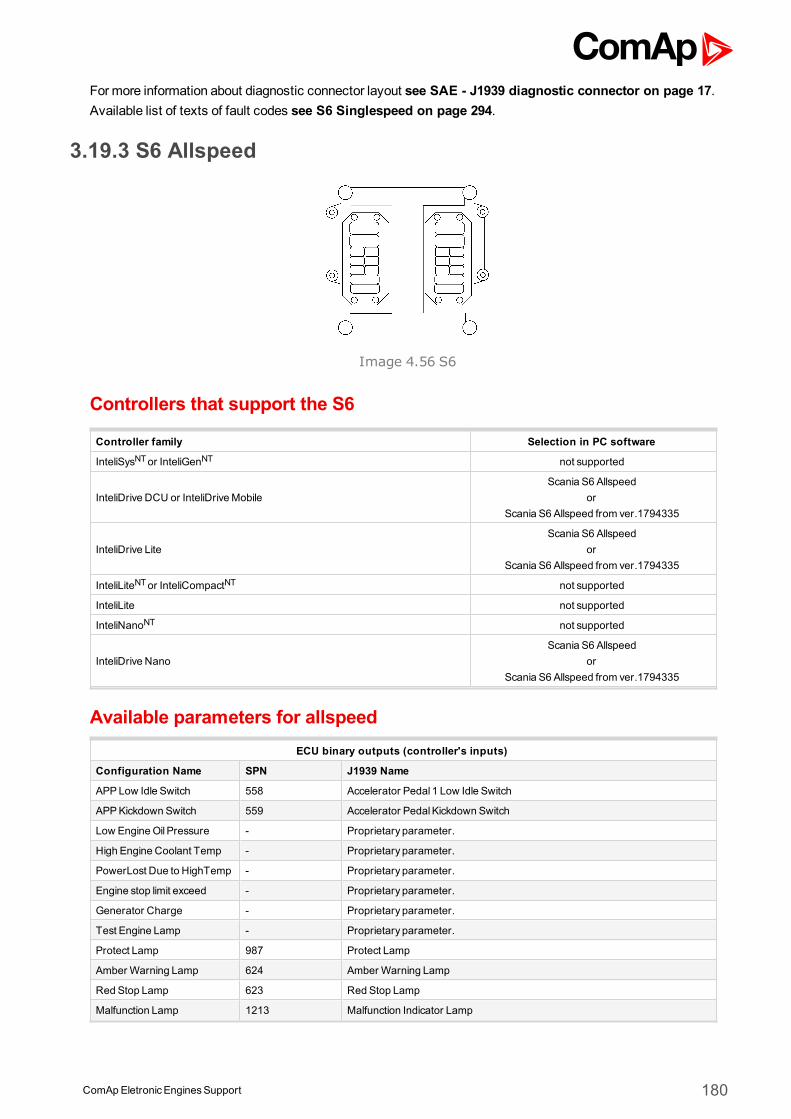
ComApEletronicEnginesSupport 180
Formore information about diagnostic connector layout see SAE - J1939 diagnostic connector on page 17.Available list of texts of fault codes see S6 Singlespeed on page 294.
3.19.3 S6 Allspeed
Image 4.56 S6
Controllers that support the S6
Controller family Selection in PC software
InteliSysNTor InteliGenNT not supported
InteliDrive DCU or InteliDriveMobileScania S6 Allspeed
orScania S6 Allspeed from ver.1794335
InteliDrive LiteScania S6 Allspeed
orScania S6 Allspeed from ver.1794335
InteliLiteNTor InteliCompactNT not supported
InteliLite not supported
InteliNanoNT not supported
InteliDrive NanoScania S6 Allspeed
orScania S6 Allspeed from ver.1794335
Available parameters for allspeedECU binary outputs (controller's inputs)
Configuration Name SPN J1939 Name
APPLow Idle Switch 558 Accelerator Pedal 1 Low Idle Switch
APPKickdown Switch 559 Accelerator PedalKickdown Switch
Low EngineOil Pressure - Proprietary parameter.
High Engine Coolant Temp - Proprietary parameter.
PowerLost Due to HighTemp - Proprietary parameter.
Engine stop limit exceed - Proprietary parameter.
Generator Charge - Proprietary parameter.
Test Engine Lamp - Proprietary parameter.
Protect Lamp 987 Protect Lamp
Amber Warning Lamp 624 Amber Warning Lamp
Red Stop Lamp 623 Red Stop Lamp
Malfunction Lamp 1213 Malfunction Indicator Lamp
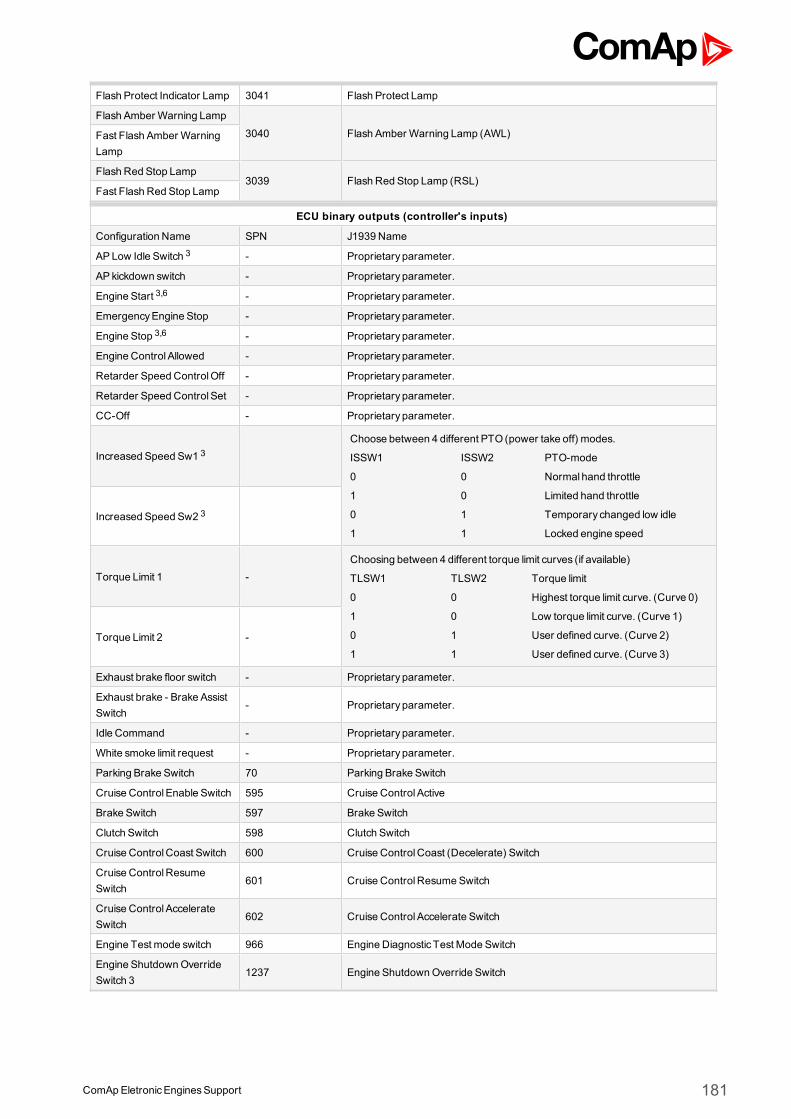
ComApEletronicEnginesSupport 181
Flash Protect Indicator Lamp 3041 Flash Protect Lamp
Flash Amber Warning Lamp
3040 Flash Amber Warning Lamp (AWL)Fast Flash Amber WarningLamp
Flash Red Stop Lamp3039 Flash Red Stop Lamp (RSL)
Fast Flash Red Stop Lamp
ECU binary outputs (controller's inputs)
Configuration Name SPN J1939 Name
APLow Idle Switch 3 - Proprietary parameter.
AP kickdown switch - Proprietary parameter.
Engine Start 3,6 - Proprietary parameter.
EmergencyEngine Stop - Proprietary parameter.
Engine Stop 3,6 - Proprietary parameter.
Engine Control Allowed - Proprietary parameter.
Retarder Speed ControlOff - Proprietary parameter.
Retarder Speed Control Set - Proprietary parameter.
CC-Off - Proprietary parameter.
Increased Speed Sw1 3Choose between 4 different PTO (power take off) modes.
ISSW1 ISSW2 PTO-mode
0 0 Normal hand throttle
1 0 Limited hand throttle
0 1 Temporary changed low idle
1 1 Locked engine speedIncreased Speed Sw2 3
Torque Limit 1 -Choosing between 4 different torque limit curves (if available)
TLSW1 TLSW2 Torque limit
0 0 Highest torque limit curve. (Curve 0)
1 0 Low torque limit curve. (Curve 1)
0 1 User defined curve. (Curve 2)
1 1 User defined curve. (Curve 3)Torque Limit 2 -
Exhaust brake floor switch - Proprietary parameter.
Exhaust brake - Brake AssistSwitch
- Proprietary parameter.
Idle Command - Proprietary parameter.
White smoke limit request - Proprietary parameter.
Parking Brake Switch 70 Parking Brake Switch
Cruise Control Enable Switch 595 Cruise Control Active
Brake Switch 597 Brake Switch
Clutch Switch 598 Clutch Switch
Cruise ControlCoast Switch 600 Cruise ControlCoast (Decelerate) Switch
Cruise ControlResumeSwitch
601 Cruise ControlResumeSwitch
Cruise Control AccelerateSwitch
602 Cruise Control Accelerate Switch
Engine Test mode switch 966 Engine Diagnostic Test Mode Switch
Engine ShutdownOverrideSwitch 3
1237 Engine ShutdownOverride Switch
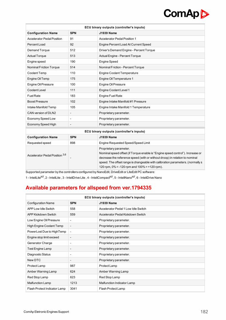
ComApEletronicEnginesSupport 182
ECU binary outputs (controller's inputs)
Configuration Name SPN J1939 Name
Accelerator PedalPosition 91 Accelerator PedalPosition 1
Percent Load 92 Engine Percent Load At Current Speed
Demand Torque 512 Driver'sDemand Engine - Percent Torque
Actual Torque 513 ActualEngine - Percent Torque
Engine speed 190 Engine Speed
Nominal Friction Torque 514 Nominal Friction - Percent Torque
Coolant Temp 110 Engine Coolant Temperature
EngineOil Temp 175 EngineOil Temperature 1
EngineOil Pressure 100 EngineOil Pressure
Coolant Level 111 Engine Coolant Level 1
FuelRate 183 Engine FuelRate
Boost Pressure 102 Engine IntakeManifold #1 Pressure
IntakeManifold Temp 105 Engine IntakeManifold 1 Temperature
CAN version of DLN2 - Proprietary parameter.
EconomySpeed Low - Proprietary parameter.
EconomySpeed High - Proprietary parameter.
ECU binary outputs (controller's inputs)
Configuration Name SPN J1939 Name
Requested speed 898 Engine Requested Speed/Speed Limit
Accelerator PedalPosition 3,6-
Proprietary parameter.Nominal speed offset (if Torque enable is “Engine speed control”). Increase ordecrease the reference speed (with or without droop) in relation to nominalspeed. The offset range is changeable with calibration parameters. (normally ±120 rpm, 0%= -120 rpm and 100%=+120 rpm).
Supported parameter by the controllers configured byNanoEdit, DriveEdit or LiteEdit PC software:
1 - InteliLiteNT, 2 - InteliLite , 3 - InteliDrive Lite , 4 - InteliCompactNT, 5 - InteliNanoNT, 6 - InteliDrive Nano
Available parameters for allspeed from ver.1794335ECU binary outputs (controller's inputs)
Configuration Name SPN J1939 Name
APPLow Idle Switch 558 Accelerator Pedal 1 Low Idle Switch
APPKickdown Switch 559 Accelerator PedalKickdown Switch
Low EngineOil Pressure - Proprietary parameter.
High Engine Coolant Temp - Proprietary parameter.
PowerLost Due to HighTemp - Proprietary parameter.
Engine stop limit exceed - Proprietary parameter.
Generator Charge - Proprietary parameter.
Test Engine Lamp - Proprietary parameter.
DiagnosticStatus - Proprietary parameter.
New DTC - Proprietary parameter.
Protect Lamp 987 Protect Lamp
Amber Warning Lamp 624 Amber Warning Lamp
Red Stop Lamp 623 Red Stop Lamp
Malfunction Lamp 1213 Malfunction Indicator Lamp
Flash Protect Indicator Lamp 3041 Flash Protect Lamp
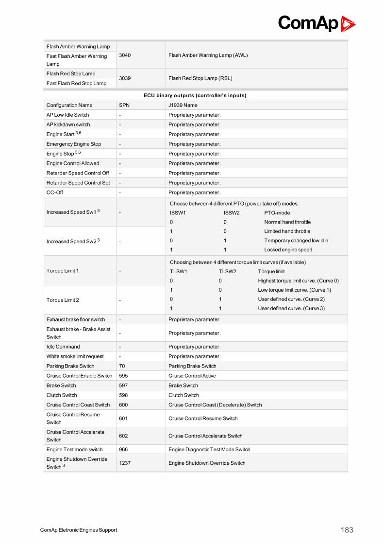
ComApEletronicEnginesSupport 183
Flash Amber Warning Lamp
3040 Flash Amber Warning Lamp (AWL)Fast Flash Amber WarningLamp
Flash Red Stop Lamp3039 Flash Red Stop Lamp (RSL)
Fast Flash Red Stop Lamp
ECU binary outputs (controller's inputs)
Configuration Name SPN J1939 Name
APLow Idle Switch - Proprietary parameter.
AP kickdown switch - Proprietary parameter.
Engine Start 3,6 - Proprietary parameter.
EmergencyEngine Stop - Proprietary parameter.
Engine Stop 3,6 - Proprietary parameter.
Engine Control Allowed - Proprietary parameter.
Retarder Speed ControlOff - Proprietary parameter.
Retarder Speed Control Set - Proprietary parameter.
CC-Off - Proprietary parameter.
Increased Speed Sw1 3 -Choose between 4 different PTO (power take off) modes.
ISSW1 ISSW2 PTO-mode
0 0 Normal hand throttle
1 0 Limited hand throttle
0 1 Temporary changed low idle
1 1 Locked engine speedIncreased Speed Sw2 3 -
Torque Limit 1 -Choosing between 4 different torque limit curves (if available)
TLSW1 TLSW2 Torque limit
0 0 Highest torque limit curve. (Curve 0)
1 0 Low torque limit curve. (Curve 1)
0 1 User defined curve. (Curve 2)
1 1 User defined curve. (Curve 3)Torque Limit 2 -
Exhaust brake floor switch - Proprietary parameter.
Exhaust brake - Brake AssistSwitch
- Proprietary parameter.
Idle Command - Proprietary parameter.
White smoke limit request - Proprietary parameter.
Parking Brake Switch 70 Parking Brake Switch
Cruise Control Enable Switch 595 Cruise Control Active
Brake Switch 597 Brake Switch
Clutch Switch 598 Clutch Switch
Cruise ControlCoast Switch 600 Cruise ControlCoast (Decelerate) Switch
Cruise ControlResumeSwitch
601 Cruise ControlResumeSwitch
Cruise Control AccelerateSwitch
602 Cruise Control Accelerate Switch
Engine Test mode switch 966 Engine Diagnostic Test Mode Switch
Engine ShutdownOverrideSwitch 3
1237 Engine ShutdownOverride Switch
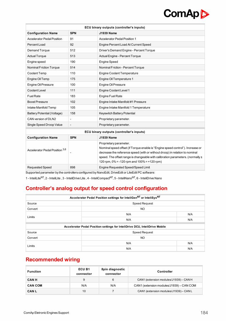
ComApEletronicEnginesSupport 184
ECU binary outputs (controller's inputs)
Configuration Name SPN J1939 Name
Accelerator PedalPosition 91 Accelerator PedalPosition 1
Percent Load 92 Engine Percent Load At Current Speed
Demand Torque 512 Driver'sDemand Engine - Percent Torque
Actual Torque 513 ActualEngine - Percent Torque
Engine speed 190 Engine Speed
Nominal Friction Torque 514 Nominal Friction - Percent Torque
Coolant Temp 110 Engine Coolant Temperature
EngineOil Temp 175 EngineOil Temperature 1
EngineOil Pressure 100 EngineOil Pressure
Coolant Level 111 Engine Coolant Level 1
FuelRate 183 Engine FuelRate
Boost Pressure 102 Engine IntakeManifold #1 Pressure
IntakeManifold Temp 105 Engine IntakeManifold 1 Temperature
BatteryPotential (Voltage) 158 Keyswitch BatteryPotential
CAN version of DLN2 - Proprietary parameter.
Single Speed Droop Value - Proprietary parameter.
ECU binary outputs (controller's inputs)
Configuration Name SPN J1939 Name
Accelerator PedalPosition 3,6-
Proprietary parameter.Nominal speed offset (if Torque enable is “Engine speed control”). Increase ordecrease the reference speed (with or without droop) in relation to nominalspeed. The offset range is changeable with calibration parameters. (normally ±120 rpm, 0%= -120 rpm and 100%=+120 rpm)
Requested Speed 898 Engine Requested Speed/Speed Limit
Supported parameter by the controllers configured byNanoEdit, DriveEdit or LiteEdit PC software:
1 - InteliLiteNT, 2 - InteliLite , 3 - InteliDrive Lite , 4 - InteliCompactNT, 5 - InteliNanoNT, 6 - InteliDrive Nano
Controller’s analog output for speed control configurationAccelerator Pedal Position settings for InteliGenNT or InteliSysNT
Source Speed Request
Convert NO
LimitsN/A N/A
N/A N/A
Accelerator Pedal Position settings for InteliDrive DCU, InteliDrive Mobile
Source Speed Request
Convert NO
LimitsN/A N/A
N/A N/A
Recommended wiring
FunctionECU B1
connector8pin diagnostic
connectorController
CAN H 9 6 CAN1 (extension modules/J1939) – CANH
CAN COM N/A N/A CAN1 (extensionmodules/J1939) – CAN COM
CAN L 10 7 CAN1 (extension modules/J1939) – CANL
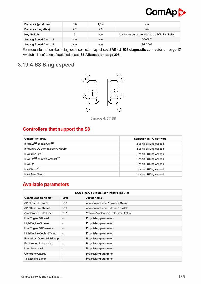
ComApEletronicEnginesSupport 185
Battery + (positive) 1,6 1,3,4 N/A
Battery - (negative) 2,7 2,5 N/A
Key Switch 3 N/A Anybinary output configured asECU PwrRelay
Analog Speed Control N/A N/A SG OUT
Analog Speed Control N/A N/A SGCOM
Formore information about diagnostic connector layout see SAE - J1939 diagnostic connector on page 17.Available list of texts of fault codes see S6 Allspeed on page 295.
3.19.4 S8 Singlespeed
Image 4.57 S8
Controllers that support the S8
Controller family Selection in PC software
InteliSysNTor InteliGenNT Scania S8 Singlespeed
InteliDrive DCU or InteliDriveMobile Scania S8 Singlespeed
InteliDrive Lite Scania S8 Singlespeed
InteliLiteNTor InteliCompactNT Scania S8 Singlespeed
InteliLite Scania S8 Singlespeed
InteliNanoNT Scania S8 Singlespeed
InteliDrive Nano Scania S8 Singlespeed
Available parametersECU binary outputs (controller's inputs)
Configuration Name SPN J1939 Name
APPLow Idle Switch 558 Accelerator Pedal 1 Low Idle Switch
APPKickdown Switch 559 Accelerator PedalKickdown Switch
Acceleration Rate Limit 2979 Vehicle Acceleration Rate Limit Status
Low EngineOil Level - Proprietary parameter.
High EngineOil Level - Proprietary parameter.
Low EngineOil Pressure - Proprietary parameter.
High Engine Coolant Temp - Proprietary parameter.
PowerLost Due to HighTemp - Proprietary parameter.
Engine stop limit exceed - Proprietary parameter.
Low Urea Level - Proprietary parameter.
Generator Charge - Proprietary parameter.
Test Engine Lamp - Proprietary parameter.
ComApEletronicEnginesSupport 186
DiagnosticStatus - Proprietary parameter.
New DTC - Proprietary parameter.
Incorrect Driver Init EngineSd
- Proprietary parameter.
GasLeakage - Proprietary parameter.
Engine Air Filter Clogged - Proprietary parameter.
Afterrun Status - Proprietary parameter.
Wait To Start Lamp 1081 EngineWait to Start Lamp
Protect Lamp 987 Protect Lamp
Amber Warning Lamp 624 Amber Warning Lamp
Red Stop Lamp 623 Red Stop Lamp
Malfunction Lamp 1213 Malfunction Indicator Lamp
Flash Protect Indicator Lamp 3041 Flash Protect Lamp
Flash Amber Warning Lamp
3040 Flash Amber Warning Lamp (AWL)Fast Flash Amber WarningLamp
Flash Red Stop Lamp3039 Flash Red Stop Lamp (RSL)
Fast Flash Red Stop Lamp
ECU binary outputs (controller's inputs)
Configuration Name SPN J1939 Name
Droop enable 1,2,3,4 - Proprietary parameter.
Torque enable - Proprietary parameter.
Engine Start 1,2,3,4,5,6 - Proprietary parameter.
EmergencyEngine Stop - Proprietary parameter.
Engine Stop 1,2,3,4,5,6 - Proprietary parameter.
Nominal speed switch 1 1,2,3,4 -Choose nominal engine speed with these switches.
NSSW1 NSSW2 Nominal speed
0 0 Use changeable calibration parameter
1 0 1500 RPM
0 1 1800 RPM
1 1 Low idle commandNominal speed switch 2 1,2,3,4 -
Torque Limit 1 -
Choosing between 4 different torque limit curves (if available)
TLSW1 TLSW2 Torque limit
0 0Highest torque limit curve. (Curve0)
1 0 Low torque limit curve. (Curve 1)
0 1 User defined curve. (Curve 2)
1 1 User defined curve. (Curve 3)
Torque Limit 2 -
Exhaust brake floor switch - Proprietary parameter.
Exhaust brake - Brake AssistSwitch
- Proprietary parameter.
Idle Command - Proprietary parameter.
White smoke limit request - Proprietary parameter.
Retarder Selection - Proprietary parameter.
ShutdownOverride Switch 1237 Engine ShutdownOverride Switch
DPF Manual Inhibit - Proprietary parameter.
ComApEletronicEnginesSupport 187
ECU binary outputs (controller's inputs)
Configuration Name SPN J1939 Name
Accelerator PedalPosition 91 Accelerator PedalPosition 1
Percent Load 92 Engine Percent Load At Current Speed
Demand Torque 512 Driver'sDemand Engine - Percent Torque
Actual Torque 513 ActualEngine - Percent Torque
Engine speed 190 Engine Speed
Nominal Friction Torque 514 Nominal Friction - Percent Torque
Coolant Temp 110 Engine Coolant Temperature
EngineOil Temp 175 EngineOil Temperature 1
EngineOil Level 98 EngineOil Level
EngineOil Pressure 100 EngineOil Pressure
Coolant Level 111 Engine Coolant Level 1
FuelRate 183 Engine FuelRate
Boost Pressure 102 Engine IntakeManifold #1 Pressure
IntakeManifold Temp 105 Engine IntakeManifold 1 Temperature
BatteryPotential 158 Keyswitch BatteryPotential
Single Speed Droop Value - Proprietary parameter.
Urea Level - Proprietary parameter.
Malfunction Indicator - Proprietary parameter.
Oil LevelMeasuring Status - Proprietary parameter.
Starter Motor NormalTemp - Proprietary parameter.
Urea level inducement state - Proprietary parameter.
ECU binary outputs (controller's inputs)
Configuration Name SPN J1939 Name
Requested speed 898 Engine Requested Speed/Speed Limit
APP - Nominal Speed Offset
1,2,3,4,5,6 -
Proprietary parameter.Nominal speed offset (if Torque enable is “Engine speed control”). Increase ordecrease the reference speed (with or without droop) in relation to nominalspeed. The offset range is changeable with calibration parameters. (normally ±120 rpm, 0%= -120 rpm and 100%=+120 rpm)
DPF ManualActivation -
Proprietary parameter.0 – No request1 – Invalidatedmanual regeneration request2 - Manual regeneration request3 – 13 – Reserved14 – Error15 – Don’t care
Supported parameter by the controllers configured byNanoEdit, DriveEdit or LiteEdit PC software:
1 - InteliLiteNT, 2 - InteliLite , 3 - InteliDrive Lite , 4 - InteliCompactNT, 5 - InteliNanoNT, 6 - InteliDrive Nano
Controller’s analog output for speed control configurationAPP - Nominal Speed Offset settings for InteliGenNT or InteliSysNT
Source Speed Request
Convert NO
LimitsN/A N/A
N/A N/A
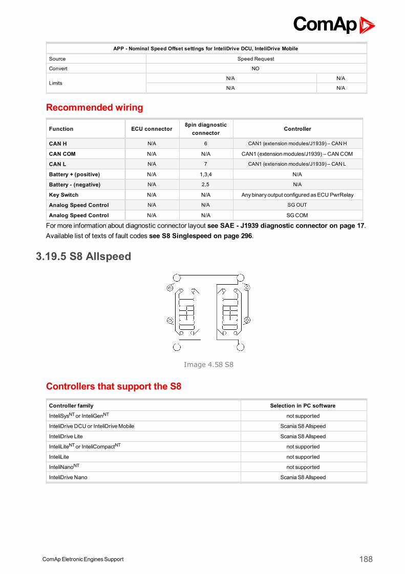
ComApEletronicEnginesSupport 188
APP - Nominal Speed Offset settings for InteliDrive DCU, InteliDrive Mobile
Source Speed Request
Convert NO
LimitsN/A N/A
N/A N/A
Recommended wiring
Function ECU connector8pin diagnostic
connectorController
CAN H N/A 6 CAN1 (extension modules/J1939) – CANH
CAN COM N/A N/A CAN1 (extensionmodules/J1939) – CAN COM
CAN L N/A 7 CAN1 (extension modules/J1939) – CANL
Battery + (positive) N/A 1,3,4 N/A
Battery - (negative) N/A 2,5 N/A
Key Switch N/A N/A Anybinary output configured asECU PwrRelay
Analog Speed Control N/A N/A SG OUT
Analog Speed Control N/A N/A SGCOM
Formore information about diagnostic connector layout see SAE - J1939 diagnostic connector on page 17.Available list of texts of fault codes see S8 Singlespeed on page 296.
3.19.5 S8 Allspeed
Image 4.58 S8
Controllers that support the S8
Controller family Selection in PC software
InteliSysNTor InteliGenNT not supported
InteliDrive DCU or InteliDriveMobile Scania S8 Allspeed
InteliDrive Lite Scania S8 Allspeed
InteliLiteNTor InteliCompactNT not supported
InteliLite not supported
InteliNanoNT not supported
InteliDrive Nano Scania S8 Allspeed
ComApEletronicEnginesSupport 189
Available parametersECU binary outputs (controller's inputs)
Configuration Name SPN J1939 Name
APPLow Idle Switch 558 Accelerator Pedal 1 Low Idle Switch
APPKickdown Switch 559 Accelerator PedalKickdown Switch
Acceleration Rate Limit 2979 Vehicle Acceleration Rate Limit Status
Low EngineOil Level - Proprietary parameter.
High EngineOil Level - Proprietary parameter.
Low EngineOil Pressure - Proprietary parameter.
High Engine Coolant Temp - Proprietary parameter.
PowerLost Due to HighTemp - Proprietary parameter.
Engine stop limit exceed - Proprietary parameter.
Low Urea Level - Proprietary parameter.
Generator Charge - Proprietary parameter.
Test Engine Lamp - Proprietary parameter.
DiagnosticStatus - Proprietary parameter.
New DTC - Proprietary parameter.
Incorrect Driver Init EngineSd
- Proprietary parameter.
GasLeakage - Proprietary parameter.
Engine Air Filter Clogged - Proprietary parameter.
Afterrun Status - Proprietary parameter.
Protect Lamp 987 Protect Lamp
Amber Warning Lamp 624 Amber Warning Lamp
Red Stop Lamp 623 Red Stop Lamp
Malfunction Lamp 1213 Malfunction Indicator Lamp
Flash Protect Indicator Lamp 3041 Flash Protect Lamp
Flash Amber Warning Lamp
3040 Flash Amber Warning Lamp (AWL)Fast Flash Amber WarningLamp
Flash Red Stop Lamp3039 Flash Red Stop Lamp (RSL)
Fast Flash Red Stop Lamp
ECU binary outputs (controller's inputs)
Configuration Name SPN J1939 Name
APLow Idle Switch Released3 - Proprietary parameter.
Engine Start 3,6 - Proprietary parameter.
EmergencyEngine Stop - Proprietary parameter.
Engine Stop 3,6 - Proprietary parameter.
Lamp Test - Proprietary parameter.
Idle Command - Proprietary parameter.
White smoke limit request - Proprietary parameter.
ShutdownOverride Switch 1237 Engine ShutdownOverride Switch
DPF Manual Inhibit - Proprietary parameter.
ECU binary outputs (controller's inputs)
Configuration Name SPN J1939 Name
Accelerator PedalPosition 91 Accelerator PedalPosition 1
ComApEletronicEnginesSupport 190
Percent Load 92 Engine Percent Load At Current Speed
Demand Torque 512 Driver'sDemand Engine - Percent Torque
Actual Torque 513 ActualEngine - Percent Torque
Engine speed 190 Engine Speed
Nominal Friction Torque 514 Nominal Friction - Percent Torque
Coolant Temp 110 Engine Coolant Temperature
EngineOil Temp 175 EngineOil Temperature 1
EngineOil Level 98 EngineOil Level
EngineOil Pressure 100 EngineOil Pressure
Coolant Level 111 Engine Coolant Level 1
FuelRate 183 Engine FuelRate
Boost Pressure 102 Engine IntakeManifold #1 Pressure
IntakeManifold Temp 105 Engine IntakeManifold 1 Temperature
BatteryPotential 158 Keyswitch BatteryPotential
Single Speed Droop Value - Proprietary parameter.
Urea Level - Proprietary parameter.
Malfunction Indicator - Proprietary parameter.
Oil LevelMeasuring Status - Proprietary parameter.
Starter Motor NormalTemp - Proprietary parameter.
Urea level inducement state - Proprietary parameter.
ECU binary outputs (controller's inputs)
Configuration Name SPN J1939 Name
Requested speed 898 Engine Requested Speed/Speed Limit
Accelerator PedalPosition 3,6-
Proprietary parameter.Nominal speed offset (if Torque enable is “Engine speed control”). Increase ordecrease the reference speed (with or without droop) in relation to nominalspeed. The offset range is changeable with calibration parameters. (normally ±120 rpm, 0%= -120 rpm and 100%=+120 rpm)
DPF ManualActivation -
Proprietary parameter.0 – No request1 – Invalidatedmanual regeneration request2 - Manual regeneration request3 – 13 – Reserved14 – Error15 – Don’t care
Supported parameter by the controllers configured byNanoEdit, DriveEdit or LiteEdit PC software:
1 - InteliLiteNT, 2 - InteliLite , 3 - InteliDrive Lite , 4 - InteliCompactNT, 5 - InteliNanoNT, 6 - InteliDrive Nano
Controller’s analog output for speed control configurationAPP - Nominal Speed Offset settings for InteliGenNT or InteliSysNT
Source Speed Request
Convert NO
LimitsN/A N/A
N/A N/A
APP - Nominal Speed Offset settings for InteliDrive DCU, InteliDrive Mobile
Source Speed Request
Convert NO
LimitsN/A N/A
N/A N/A
ComApEletronicEnginesSupport 191
Recommended wiring
Function ECU connector8pin diagnostic
connectorController
CAN H N/A 6 CAN1 (extension modules/J1939) – CANH
CAN COM N/A N/A CAN1 (extensionmodules/J1939) – CAN COM
CAN L N/A 7 CAN1 (extension modules/J1939) – CANL
Battery + (positive) N/A 1,3,4 N/A
Battery - (negative) N/A 2,5 N/A
Key Switch N/A N/A Anybinary output configured asECU PwrRelay
Analog Speed Control N/A N/A SG OUT
Analog Speed Control N/A N/A SGCOM
Formore information about diagnostic connector layout see SAE - J1939 diagnostic connector on page 17.Available list of texts of fault codes see S8 Allspeed on page 297.
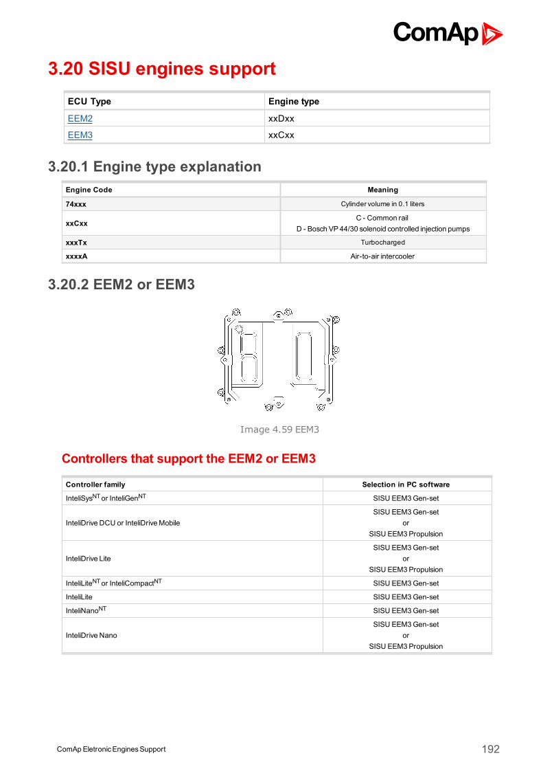
ComApEletronicEnginesSupport 192
3.20 SISU engines supportECU Type Engine type
EEM2 xxDxx
EEM3 xxCxx
3.20.1 Engine type explanationEngine Code Meaning
74xxx Cylinder volume in 0.1 liters
xxCxxC - Common rail
D - Bosch VP44/30 solenoid controlled injection pumps
xxxTx Turbocharged
xxxxA Air-to-air intercooler
3.20.2 EEM2 or EEM3
Image 4.59 EEM3
Controllers that support the EEM2 or EEM3
Controller family Selection in PC software
InteliSysNTor InteliGenNT SISU EEM3Gen-set
InteliDrive DCU or InteliDriveMobileSISU EEM3Gen-set
orSISU EEM3Propulsion
InteliDrive LiteSISU EEM3Gen-set
orSISU EEM3Propulsion
InteliLiteNTor InteliCompactNT SISU EEM3Gen-set
InteliLite SISU EEM3Gen-set
InteliNanoNT SISU EEM3Gen-set
InteliDrive NanoSISU EEM3Gen-set
orSISU EEM3Propulsion
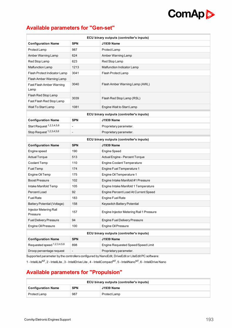
ComApEletronicEnginesSupport 193
Available parameters for "Gen-set"ECU binary outputs (controller's inputs)
Configuration Name SPN J1939 Name
Protect Lamp 987 Protect Lamp
Amber Warning Lamp 624 Amber Warning Lamp
Red Stop Lamp 623 Red Stop Lamp
Malfunction Lamp 1213 Malfunction Indicator Lamp
Flash Protect Indicator Lamp 3041 Flash Protect Lamp
Flash Amber Warning Lamp
3040 Flash Amber Warning Lamp (AWL)Fast Flash Amber WarningLamp
Flash Red Stop Lamp3039 Flash Red Stop Lamp (RSL)
Fast Flash Red Stop Lamp
Wait To Start Lamp 1081 EngineWait to Start Lamp
ECU binary outputs (controller's inputs)
Configuration Name SPN J1939 Name
Start Request 1,2,3,4,5,6 - Proprietary parameter.
Stop Request 1,2,3,4,5,6 - Proprietary parameter.
ECU binary outputs (controller's inputs)
Configuration Name SPN J1939 Name
Engine speed 190 Engine Speed
Actual Torque 513 ActualEngine - Percent Torque
Coolant Temp 110 Engine Coolant Temperature
Fuel Temp 174 Engine Fuel Temperature 1
EngineOil Temp 175 EngineOil Temperature 1
Boost Pressure 102 Engine IntakeManifold #1 Pressure
IntakeManifold Temp 105 Engine IntakeManifold 1 Temperature
Percent Load 92 Engine Percent Load At Current Speed
FuelRate 183 Engine FuelRate
BatteryPotential (Voltage) 158 Keyswitch BatteryPotential
Injector Metering RailPressure
157 Engine Injector Metering Rail 1 Pressure
FuelDeliveryPressure 94 Engine FuelDeliveryPressure
EngineOil Pressure 100 EngineOil Pressure
ECU binary outputs (controller's inputs)
Configuration Name SPN J1939 Name
Requested speed 1,2,3,4,5,6 898 Engine Requested Speed/Speed Limit
Droop percentage request - Proprietary parameter.
Supported parameter by the controllers configured byNanoEdit, DriveEdit or LiteEdit PC software:
1 - InteliLiteNT, 2 - InteliLite , 3 - InteliDrive Lite , 4 - InteliCompactNT, 5 - InteliNanoNT, 6 - InteliDrive Nano
Available parameters for "Propulsion"ECU binary outputs (controller's inputs)
Configuration Name SPN J1939 Name
Protect Lamp 987 Protect Lamp
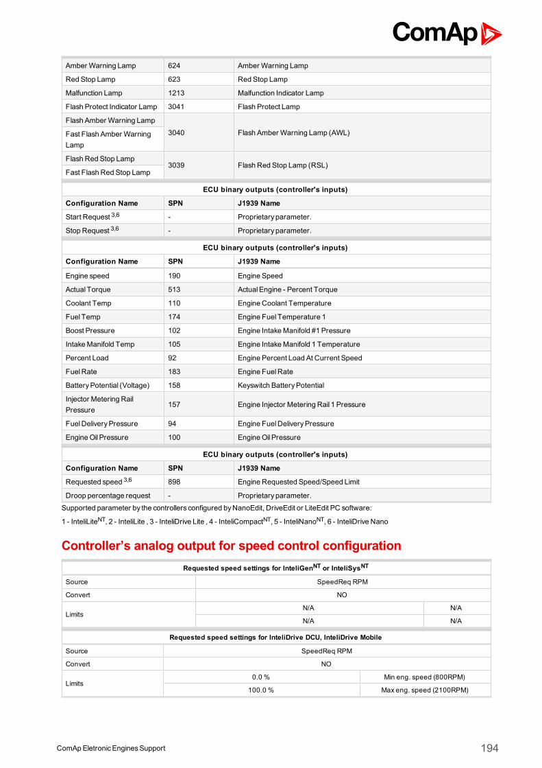
ComApEletronicEnginesSupport 194
Amber Warning Lamp 624 Amber Warning Lamp
Red Stop Lamp 623 Red Stop Lamp
Malfunction Lamp 1213 Malfunction Indicator Lamp
Flash Protect Indicator Lamp 3041 Flash Protect Lamp
Flash Amber Warning Lamp
3040 Flash Amber Warning Lamp (AWL)Fast Flash Amber WarningLamp
Flash Red Stop Lamp3039 Flash Red Stop Lamp (RSL)
Fast Flash Red Stop Lamp
ECU binary outputs (controller's inputs)
Configuration Name SPN J1939 Name
Start Request 3,6 - Proprietary parameter.
Stop Request 3,6 - Proprietary parameter.
ECU binary outputs (controller's inputs)
Configuration Name SPN J1939 Name
Engine speed 190 Engine Speed
Actual Torque 513 ActualEngine - Percent Torque
Coolant Temp 110 Engine Coolant Temperature
Fuel Temp 174 Engine Fuel Temperature 1
Boost Pressure 102 Engine IntakeManifold #1 Pressure
IntakeManifold Temp 105 Engine IntakeManifold 1 Temperature
Percent Load 92 Engine Percent Load At Current Speed
FuelRate 183 Engine FuelRate
BatteryPotential (Voltage) 158 Keyswitch BatteryPotential
Injector Metering RailPressure
157 Engine Injector Metering Rail 1 Pressure
FuelDeliveryPressure 94 Engine FuelDeliveryPressure
EngineOil Pressure 100 EngineOil Pressure
ECU binary outputs (controller's inputs)
Configuration Name SPN J1939 Name
Requested speed 3,6 898 Engine Requested Speed/Speed Limit
Droop percentage request - Proprietary parameter.
Supported parameter by the controllers configured byNanoEdit, DriveEdit or LiteEdit PC software:
1 - InteliLiteNT, 2 - InteliLite , 3 - InteliDrive Lite , 4 - InteliCompactNT, 5 - InteliNanoNT, 6 - InteliDrive Nano
Controller’s analog output for speed control configurationRequested speed settings for InteliGenNT or InteliSysNT
Source SpeedReq RPM
Convert NO
LimitsN/A N/A
N/A N/A
Requested speed settings for InteliDrive DCU, InteliDrive Mobile
Source SpeedReq RPM
Convert NO
Limits0.0 % Min eng. speed (800RPM)
100.0 % Max eng. speed (2100RPM)
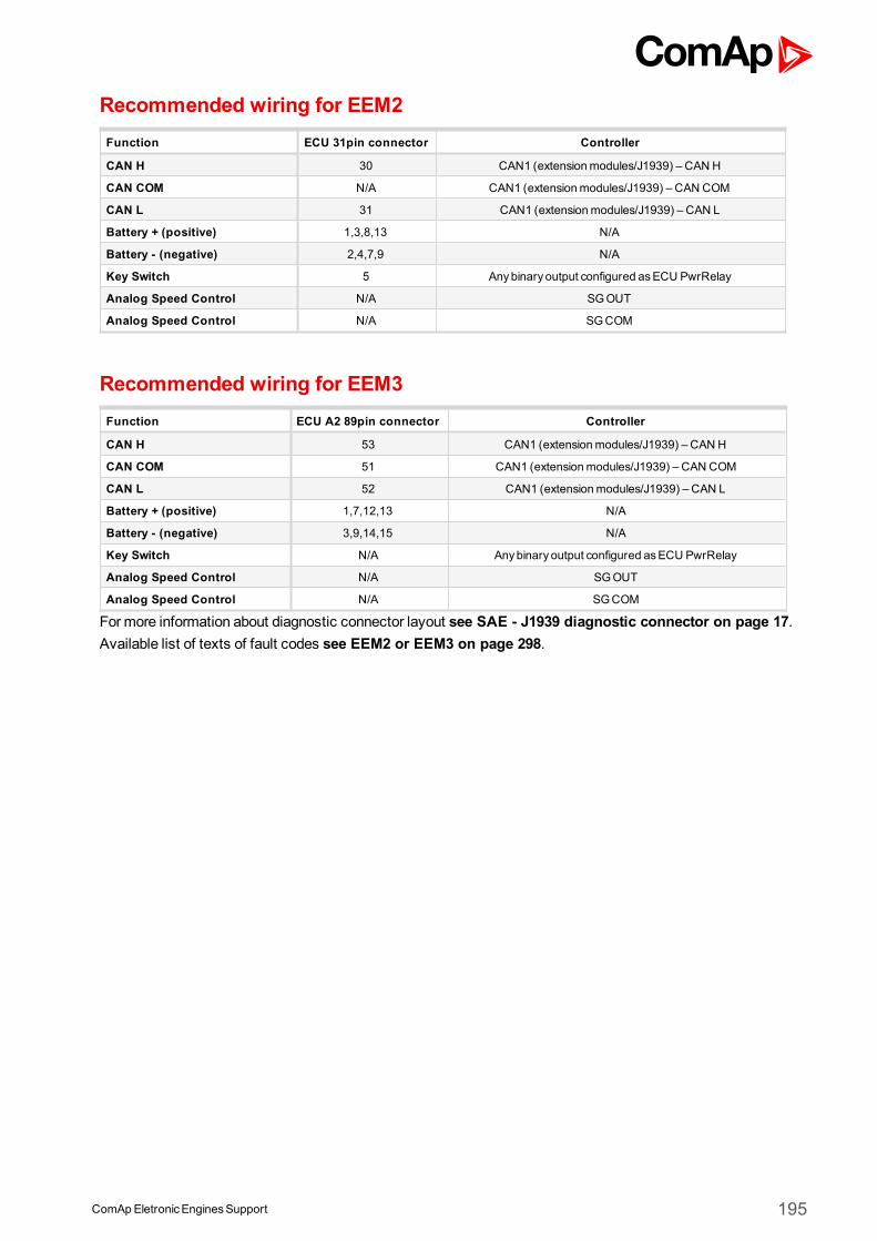
ComApEletronicEnginesSupport 195
Recommended wiring for EEM2Function ECU 31pin connector Controller
CAN H 30 CAN1 (extensionmodules/J1939) – CAN H
CAN COM N/A CAN1 (extensionmodules/J1939) – CAN COM
CAN L 31 CAN1 (extensionmodules/J1939) – CAN L
Battery + (positive) 1,3,8,13 N/A
Battery - (negative) 2,4,7,9 N/A
Key Switch 5 Anybinary output configured asECU PwrRelay
Analog Speed Control N/A SGOUT
Analog Speed Control N/A SGCOM
Recommended wiring for EEM3Function ECU A2 89pin connector Controller
CAN H 53 CAN1 (extensionmodules/J1939) – CAN H
CAN COM 51 CAN1 (extensionmodules/J1939) – CAN COM
CAN L 52 CAN1 (extensionmodules/J1939) – CAN L
Battery + (positive) 1,7,12,13 N/A
Battery - (negative) 3,9,14,15 N/A
Key Switch N/A Anybinary output configured asECU PwrRelay
Analog Speed Control N/A SGOUT
Analog Speed Control N/A SGCOM
Formore information about diagnostic connector layout see SAE - J1939 diagnostic connector on page 17.Available list of texts of fault codes see EEM2 or EEM3 on page 298.
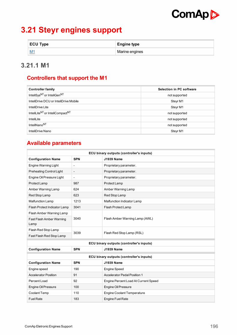
ComApEletronicEnginesSupport 196
3.21 Steyr engines supportECU Type Engine type
M1 Marine engines
3.21.1 M1
Controllers that support the M1
Controller family Selection in PC software
InteliSysNTor InteliGenNT not supported
InteliDrive DCU or InteliDriveMobile Steyr M1
InteliDrive Lite Steyr M1
InteliLiteNTor InteliCompactNT not supported
InteliLite not supported
InteliNanoNT not supported
InteliDrive Nano Steyr M1
Available parametersECU binary outputs (controller's inputs)
Configuration Name SPN J1939 Name
EngineWarning Light - Proprietary parameter.
Preheating Control Light - Proprietary parameter.
EngineOil Pressure Light - Proprietary parameter.
Protect Lamp 987 Protect Lamp
Amber Warning Lamp 624 Amber Warning Lamp
Red Stop Lamp 623 Red Stop Lamp
Malfunction Lamp 1213 Malfunction Indicator Lamp
Flash Protect Indicator Lamp 3041 Flash Protect Lamp
Flash Amber Warning Lamp
3040 Flash Amber Warning Lamp (AWL)Fast Flash Amber WarningLamp
Flash Red Stop Lamp3039 Flash Red Stop Lamp (RSL)
Fast Flash Red Stop Lamp
ECU binary outputs (controller's inputs)
Configuration Name SPN J1939 Name
ECU binary outputs (controller's inputs)
Configuration Name SPN J1939 Name
Engine speed 190 Engine Speed
Accelerator Position 91 Accelerator PedalPosition 1
Percent Load 92 Engine Percent Load At Current Speed
EngineOil Pressure 100 EngineOil Pressure
Coolant Temp 110 Engine Coolant Temperature
FuelRate 183 Engine FuelRate
ComApEletronicEnginesSupport 197
Boost Pressure 102 Engine IntakeManifold #1 Pressure
Exhaust GasTemp 173 Engine Exhaust Temperature
Keyswitch BatteryPotential 158 Keyswitch BatteryPotential
ECU binary outputs (controller's inputs)
Configuration Name SPN J1939 Name
Recommended wiringNo documentation available so far!
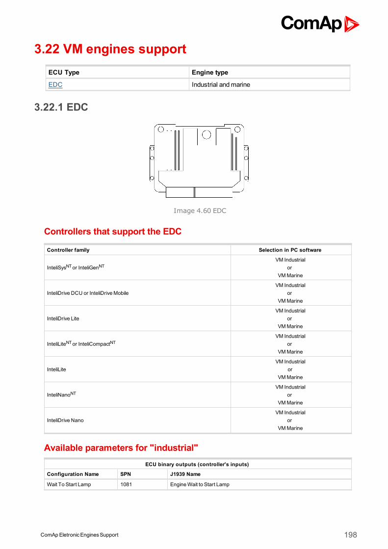
ComApEletronicEnginesSupport 198
3.22 VM engines supportECU Type Engine type
EDC Industrial andmarine
3.22.1 EDC
Image 4.60 EDC
Controllers that support the EDC
Controller family Selection in PC software
InteliSysNTor InteliGenNTVM Industrial
orVMMarine
InteliDrive DCU or InteliDriveMobileVM Industrial
orVMMarine
InteliDrive LiteVM Industrial
orVMMarine
InteliLiteNTor InteliCompactNTVM Industrial
orVMMarine
InteliLiteVM Industrial
orVMMarine
InteliNanoNTVM Industrial
orVMMarine
InteliDrive NanoVM Industrial
orVMMarine
Available parameters for "industrial"ECU binary outputs (controller's inputs)
Configuration Name SPN J1939 Name
Wait To Start Lamp 1081 EngineWait to Start Lamp
ComApEletronicEnginesSupport 199
Water in Fuel 97 Water In Fuel Indicator 1
Protect Lamp 987 Protect Lamp
Amber Warning Lamp 624 Amber Warning Lamp
Red Stop Lamp 623 Red Stop Lamp
Malfunction Lamp 1213 Malfunction Indicator Lamp
Flash Protect Indicator Lamp 3041 Flash Protect Lamp
Flash Amber Warning Lamp
3040 Flash Amber Warning Lamp (AWL)Fast Flash Amber WarningLamp
Flash Red Stop Lamp3039 Flash Red Stop Lamp (RSL)
Fast Flash Red Stop Lamp
PTOEnable Switch 980 Engine PTOGovernor Enable Switch
PTOCost/Decelerate Switch 983 Engine PTOGovernor Coast/Decelerate Switch
PTOResumeSwitch 982 Engine PTOGovernor ResumeSwitch
PTOAccelerate Switch 981 Engine PTOGovernor Accelerate Switch
ECU binary outputs (controller's inputs)
Configuration Name SPN J1939 Name
Stop Request 1,2,3,4,5,6 - Proprietary parameter.
Parking Brake Switch 70 Parking Brake Switch
Cruise Control Enable Switch 596 Cruise Control Enable Switch
Brake Switch 597 Brake Switch
Clutch Switch 598 Clutch Switch
Cruise ControlCoast Switch 600 Cruise ControlCoast (Decelerate) Switch
Cruise ControlResumeSwitch
601 Cruise ControlResumeSwitch
Cruise Control AccelerateSwitch
602 Cruise Control Accelerate Switch
ECU binary outputs (controller's inputs)
Configuration Name SPN J1939 Name
Engine speed 190 Engine Speed
Actual Torque 513 ActualEngine - Percent Torque
Demand Torque 512 Driver'sDemand Engine - Percent Torque
Coolant Temp 110 Engine Coolant Temperature
Fuel Temp 174 Engine Fuel Temperature 1
EngineOil Temp 175 EngineOil Temperature 1
BarometricPressure 108 BarometricPressure
Boost Pressure 102 Engine IntakeManifold #1 Pressure
IntakeManifold Temp 105 Engine IntakeManifold 1 Temperature
PartTrapSootLoad 3719 Aftertreatment 1 DieselParticulate Filter Soot Load Percent
PartTrapAshLoad 3720 Aftertreatment 1 DieselParticulate Filter Ash Load Percent
Estimated Percent FanSpeed
975 Engine Fan 1 Estimated Percent Speed
Accelerator PedalPosition 91 Accelerator PedalPosition 1
Percent Load 92 Engine Percent Load At Current Speed
FuelRate 183 Engine FuelRate
BatteryPotential (Voltage) 158 Keyswitch BatteryPotential
ComApEletronicEnginesSupport 200
FuelDeliveryPressure 94 Engine FuelDeliveryPressure
EngineOil Pressure 100 EngineOil Pressure
Exhaust GasTemperature 173 Engine Exhaust Temperature
ECU binary outputs (controller's inputs)
Configuration Name SPN J1939 Name
Requested speed 1,2,3,4,5,6 898 Engine Requested Speed/Speed Limit
PTOState 976 PTOGovernor State
Supported parameter by the controllers configured byNanoEdit, DriveEdit or LiteEdit PC software:
1 - InteliLiteNT, 2 - InteliLite , 3 - InteliDrive Lite , 4 - InteliCompactNT, 5 - InteliNanoNT, 6 - InteliDrive Nano
Available parameters for "marine"ECU binary outputs (controller's inputs)
Configuration Name SPN J1939 Name
Wait To Start Lamp 1081 EngineWait to Start Lamp
Protect Lamp 987 Protect Lamp
Amber Warning Lamp 624 Amber Warning Lamp
Red Stop Lamp 623 Red Stop Lamp
Malfunction Lamp 1213 Malfunction Indicator Lamp
Flash Protect Indicator Lamp 3041 Flash Protect Lamp
Flash Amber Warning Lamp
3040 Flash Amber Warning Lamp (AWL)Fast Flash Amber WarningLamp
Flash Red Stop Lamp3039 Flash Red Stop Lamp (RSL)
Fast Flash Red Stop Lamp
PTOEnable Switch 980 Engine PTOGovernor Enable Switch
PTOCost/Decelerate Switch 983 Engine PTOGovernor Coast/Decelerate Switch
PTOResumeSwitch 982 Engine PTOGovernor ResumeSwitch
PTOAccelerate Switch 981 Engine PTOGovernor Accelerate Switch
ECU binary outputs (controller's inputs)
Configuration Name SPN J1939 Name
Stop Request - Proprietary parameter.
Parking Brake Switch 70 Parking Brake Switch
Cruise Control Enable Switch 596 Cruise Control Enable Switch
Brake Switch 597 Brake Switch
Clutch Switch 598 Clutch Switch
Cruise ControlCoast Switch 600 Cruise ControlCoast (Decelerate) Switch
Cruise ControlResumeSwitch
601 Cruise ControlResumeSwitch
Cruise Control AccelerateSwitch
602 Cruise Control Accelerate Switch
ECU binary outputs (controller's inputs)
Configuration Name SPN J1939 Name
Engine speed 190 Engine Speed
Actual Torque 513 ActualEngine - Percent Torque
Demand Torque 512 Driver'sDemand Engine - Percent Torque
Coolant Temp 110 Engine Coolant Temperature
Fuel Temp 174 Engine Fuel Temperature 1
ComApEletronicEnginesSupport 201
EngineOil Temp 175 EngineOil Temperature 1
BarometricPressure 108 BarometricPressure
Boost Pressure 102 Engine IntakeManifold #1 Pressure
IntakeManifold Temp 105 Engine IntakeManifold 1 Temperature
Estimated Percent FanSpeed
975 Engine Fan 1 Estimated Percent Speed
Accelerator PedalPosition 91 Accelerator PedalPosition 1
Percent Load 92 Engine Percent Load At Current Speed
FuelRate 183 Engine FuelRate
BatteryPotential (Voltage) 158 Keyswitch BatteryPotential
FuelDeliveryPressure 94 Engine FuelDeliveryPressure
EngineOil Pressure 100 EngineOil Pressure
ECU binary outputs (controller's inputs)
Configuration Name SPN J1939 Name
Requested speed 898 Engine Requested Speed/Speed Limit
PTOState 976 PTOGovernor State
Controller’s analog output for speed control configurationRequested speed settings for InteliGenNT or InteliSysNT
Source SpeedReq RPM
Convert NO
LimitsN/A N/A
N/A N/A
Requested speed settings for InteliDrive DCU, InteliDrive Mobile
Source SpeedReq RPM
Convert NO
Limits0.0 % Min eng. speed (800RPM)
100.0 % Max eng. speed (2100RPM)
Recommended wiringFunction ECU connector Controller
CAN H 62 CAN1 (extensionmodules/J1939) – CAN H
CAN COM N/A CAN1 (extensionmodules/J1939) – CAN COM
CAN L 83 CAN1 (extensionmodules/J1939) – CAN L
Battery + (positive) 1,5 N/A
Battery - (negative) 2,4,6 N/A
Key Switch 28 Anybinary output configured asECU PwrRelay
Analog Speed Control N/A SGOUT
Analog Speed Control N/A SGCOM
Formore information about diagnostic connector layout see SAE - J1939 diagnostic connector on page 17.Available list of texts of fault codes see EDC on page 299.
ComApEletronicEnginesSupport 202
3.22.2 M1
Image 4.61 M1
Controllers that support the M1
Selection in PC software
InteliSysNT or InteliGenNT Steyr M1
InteliDrive DCU or InteliDrive Mobile
InteliDrive Lite not supported
InteliLiteNT or InteliCompactNT not supported
InteliNanoNT not supported
InteliDrive Nano not supported
Available parametersECU binary outputs (controller's inputs)
Configuration Name SPN J1939 Name
EngineWarning Light - Proprietary parameter.
Preheating Control Light - Proprietary parameter.
EngineOil Pressure Light - Proprietary parameter.
Protect Lamp 987 Protect Lamp
Amber Warning Lamp 624 Amber Warning Lamp
Red Stop Lamp 623 Red Stop Lamp
Malfunction Lamp 1213 Malfunction Indicator Lamp
ECU binary outputs (controller's inputs)
Configuration Name SPN J1939 Name
ECU binary outputs (controller's inputs)
Configuration Name SPN J1939 Name
Engine speed 190 Engine Speed
Accelerator Position 91 Accelerator PedalPosition 1
Percent Load 92 Engine Percent Load At Current Speed
EngineOil Pressure 100 EngineOil Pressure
Coolant Temp 110 Engine Coolant Temperature
FuelRate 183 Engine FuelRate
Boost Pressure 102 Engine IntakeManifold #1 Pressure
Exhaust GasTemp 173 Engine Exhaust Temperature
Keyswitch BatteryPotential 158 Keyswitch BatteryPotential
ECU binary outputs (controller's inputs)
Configuration Name SPN J1939 Name
Recommended wiringNo documentation available so far!

ComApEletronicEnginesSupport 203
ComApEletronicEnginesSupport 204
3.23 Volvo engines supportECU Type Engine type
EDC3 Singlespeed (EMS1)EDC3 Allspeed (EMS1)
D12
EMS2 D9, D16, D724
EDC4 (EMR2) D5, D7
3.23.1 Engine type explanationEngine Code Meaning
Txxxxxxxx Turbocharged
xAxxxxxxx Air to air intercooled
xxDxxxxxx Diesel fuel
xxx16xxxx Displacement indication
xxxxx3xxx Generation
xxxxxx0xx Version
xxxxxxxGx Generator drive
xxxxxxxxE Emission controlled
Note: Standalone connection (hardwired speed potentiometer). On D12 industrial gen-set engines it's possibleto connect standalone connection. If there is a ComAp panel connected via CAN bus during power up theengine will detect this and will be controlled via CAN bus. But if the ComAp panel is dead during power up theengine and if there is connected a potentiometer on standalone connector the engine will detect this and will runin stand alonemode.
3.23.2 Volvo Singlespeed EDC3 / EMS1 / EMS2
Image 4.62 EMS2
Controllers that support the EMS2
Controller family Selection in PC software
InteliSysNTor InteliGenNT Volvo Singlespeed
InteliDrive DCU or InteliDriveMobile Volvo Singlespeed
InteliDrive Lite Volvo Singlespeed
ComApEletronicEnginesSupport 205
InteliLiteNTor InteliCompactNT Volvo Singlespeed
InteliLite Volvo Singlespeed
InteliNanoNT Volvo Singlespeed
InteliDrive Nano Volvo Singlespeed
Available parametersECU binary outputs (controller's inputs)
Configuration Name SPN J1939 Name
Preheat Indication -Proprietary parameter.The statusof the preheat relay.
Running Indication -Proprietary parameter.The running statusof the engine.
Overspeed Alarm -Proprietary parameter.Statusof the (virtual) overspeed alarm switch.
Oil Pressure Alarm -Proprietary parameter.The statusof the (virtual) oil pressure alarm switch.
Oil Temperature Alarm -Proprietary parameter.The statusof the (virtual) oil temperature alarm switch.
Coolant Temperature -Proprietary parameter.The statusof the (virtual) coolant temperature alarm switch.
Coolant LevelAlarm -Proprietary parameter.The statusof the coolant level alarm switch.
Charge Alarm -Proprietary parameter.The statusof the (virtual) charge alarm switch.
Buzzer -Proprietary parameter.Controls the buzzer.
EngineOil Filter Diff.Press -Proprietary parameter.The statusof the engine oil filters differential pressure alarm.
FuelPressure Alarm -Proprietary parameter.The statusof the Fuel pressure alarm.
Override Indication -Proprietary parameter.The statusof the engine protection override.
General Lamptest -Proprietary parameter.Controls the general lamptest.
Buzzer/Lamptest -Proprietary parameter.Controls the buzzertest / lamptest.
EMSDiagnoseYellowLamp -Proprietary parameter.The statusof the yellow diagnose lamp of the EMS (Mirror of PID 44, J1587).
EMSDiagnoseRedLamp -Proprietary parameter.The statusof the red diagnose lamp of the EMS (Mirror of PID 44, J1587)
PrimaryBat.Status -Proprietary parameter.Statusof the primary battery circuit.
SecondaryBat.Status -Proprietary parameter.Statusof the secondary battery circuit.
15 Fuse Status -Proprietary parameter.The of the 15 supply fuse.
30 Fuse Status -Proprietary parameter.The of the 30 supply fuse.
EMSFuse Status -Proprietary parameter.The of the EMSsupply fuse.
Extra Fuse Status - Proprietary parameter.
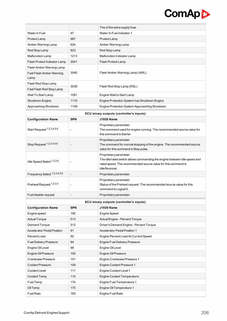
ComApEletronicEnginesSupport 206
The of the extra supply fuse.
Water in Fuel 97 Water In Fuel Indicator 1
Protect Lamp 987 Protect Lamp
Amber Warning Lamp 624 Amber Warning Lamp
Red Stop Lamp 623 Red Stop Lamp
Malfunction Lamp 1213 Malfunction Indicator Lamp
Flash Protect Indicator Lamp 3041 Flash Protect Lamp
Flash Amber Warning Lamp
3040 Flash Amber Warning Lamp (AWL)Fast Flash Amber WarningLamp
Flash Red Stop Lamp3039 Flash Red Stop Lamp (RSL)
Fast Flash Red Stop Lamp
Wait To Start Lamp 1081 EngineWait to Start Lamp
Shutdown Engine 1110 Engine Protection System hasShutdown Engine
Approaching Shutdown 1109 Engine Protection SystemApproaching Shutdown
ECU binary outputs (controller's inputs)
Configuration Name SPN J1939 Name
Start Request 1,2,3,4,5,6 -Proprietary parameter.The command used for engine running. The recommended source value forthis command isStarter.
Stop Request 1,2,3,4,5,6 -Proprietary parameter.The command for normal stopping of the engine. The recommended sourcevalue for this command isStop pulse.
Idle Speed Select 1,2,3,4 -
Proprietary parameter.The idle/rated switch allowscommanding the engine between idle speed andrated speed. The recommended source value for this command isIdle/Nominal.
FrequencySelect 1,2,3,4,5,6 - Proprietary parameter.
Preheat Request 1,2,3,4 -Proprietary parameter.Statusof the Preheat request. The recommended source value for thiscommand is Logical 0.
Fuel disable request - Proprietary parameter.
ECU binary outputs (controller's inputs)
Configuration Name SPN J1939 Name
Engine speed 190 Engine Speed
Actual Torque 513 ActualEngine - Percent Torque
Demand Torque 512 Driver'sDemand Engine - Percent Torque
Accelerator PedalPosition 91 Accelerator PedalPosition 1
Percent Load 92 Engine Percent Load At Current Speed
FuelDeliveryPressure 94 Engine FuelDeliveryPressure
EngineOil Level 98 EngineOil Level
EngineOil Pressure 100 EngineOil Pressure
Crankcase Pressure 101 Engine Crankcase Pressure 1
Coolant Pressure 109 Engine Coolant Pressure 1
Coolant Level 111 Engine Coolant Level 1
Coolant Temp 110 Engine Coolant Temperature
Fuel Temp 174 Engine Fuel Temperature 1
Oil Temp 175 EngineOil Temperature 1
FuelRate 183 Engine FuelRate
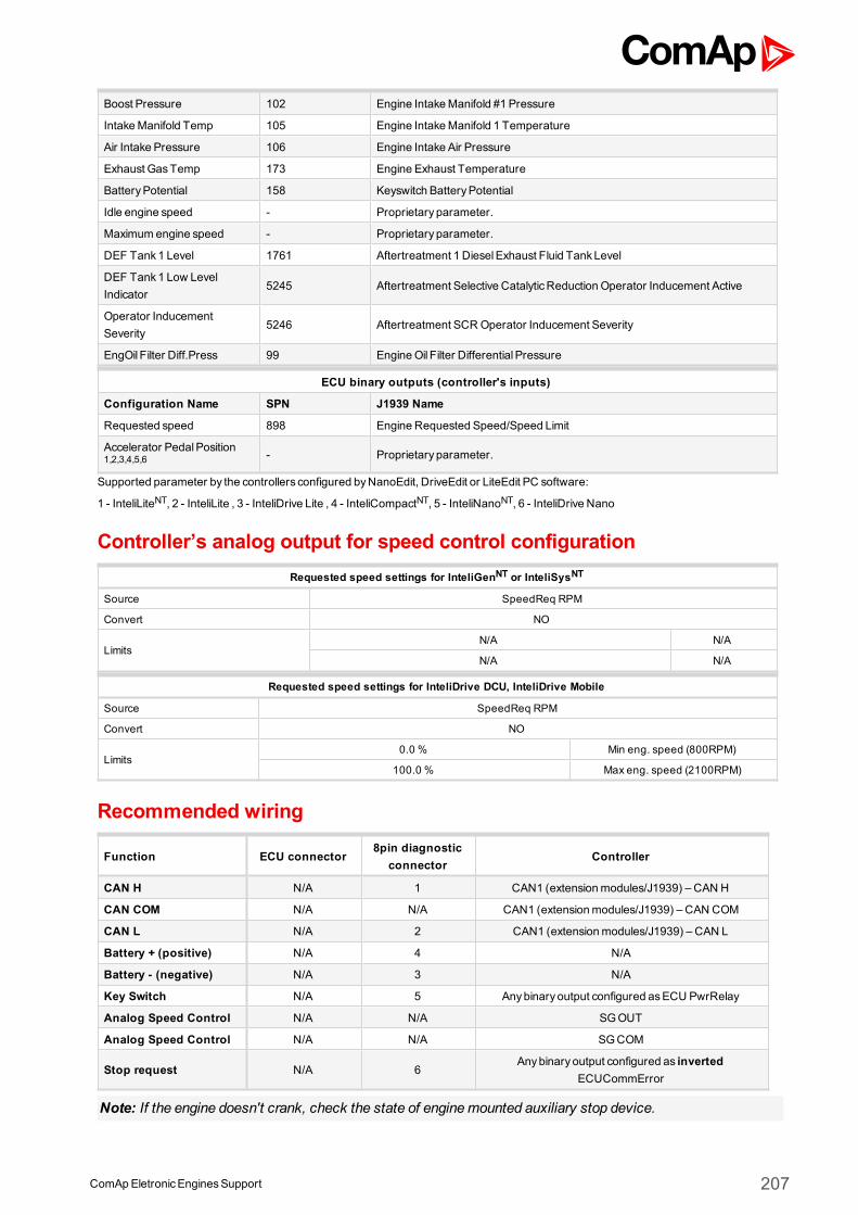
ComApEletronicEnginesSupport 207
Boost Pressure 102 Engine IntakeManifold #1 Pressure
IntakeManifold Temp 105 Engine IntakeManifold 1 Temperature
Air Intake Pressure 106 Engine Intake Air Pressure
Exhaust GasTemp 173 Engine Exhaust Temperature
BatteryPotential 158 Keyswitch BatteryPotential
Idle engine speed - Proprietary parameter.
Maximum engine speed - Proprietary parameter.
DEF Tank1 Level 1761 Aftertreatment 1 DieselExhaust Fluid TankLevel
DEF Tank1 Low LevelIndicator
5245 Aftertreatment Selective CatalyticReduction Operator Inducement Active
Operator InducementSeverity
5246 Aftertreatment SCROperator Inducement Severity
EngOil Filter Diff.Press 99 EngineOil Filter Differential Pressure
ECU binary outputs (controller's inputs)
Configuration Name SPN J1939 Name
Requested speed 898 Engine Requested Speed/Speed Limit
Accelerator PedalPosition1,2,3,4,5,6 - Proprietary parameter.
Supported parameter by the controllers configured byNanoEdit, DriveEdit or LiteEdit PC software:
1 - InteliLiteNT, 2 - InteliLite , 3 - InteliDrive Lite , 4 - InteliCompactNT, 5 - InteliNanoNT, 6 - InteliDrive Nano
Controller’s analog output for speed control configurationRequested speed settings for InteliGenNT or InteliSysNT
Source SpeedReq RPM
Convert NO
LimitsN/A N/A
N/A N/A
Requested speed settings for InteliDrive DCU, InteliDrive Mobile
Source SpeedReq RPM
Convert NO
Limits0.0 % Min eng. speed (800RPM)
100.0 % Max eng. speed (2100RPM)
Recommended wiring
Function ECU connector8pin diagnostic
connectorController
CAN H N/A 1 CAN1 (extensionmodules/J1939) – CAN H
CAN COM N/A N/A CAN1 (extensionmodules/J1939) – CAN COM
CAN L N/A 2 CAN1 (extensionmodules/J1939) – CAN L
Battery + (positive) N/A 4 N/A
Battery - (negative) N/A 3 N/A
Key Switch N/A 5 Anybinary output configured asECU PwrRelay
Analog Speed Control N/A N/A SGOUT
Analog Speed Control N/A N/A SGCOM
Stop request N/A 6Anybinary output configured as inverted
ECUCommError
Note: If the engine doesn't crank, check the state of enginemounted auxiliary stop device.
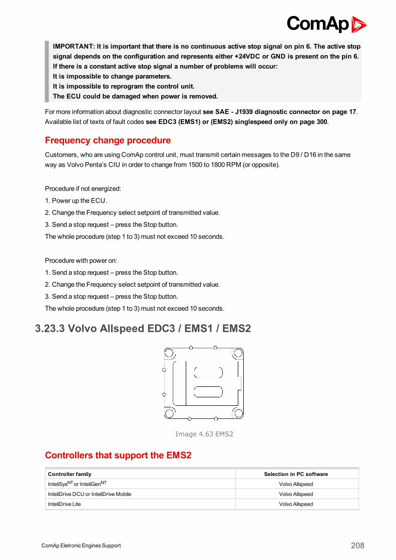
ComApEletronicEnginesSupport 208
IMPORTANT: It is important that there is no continuous active stop signal on pin 6. The active stopsignal depends on the configuration and represents either +24VDC or GND is present on the pin 6.If there is a constant active stop signal a number of problems will occur:It is impossible to change parameters.It is impossible to reprogram the control unit.The ECU could be damaged when power is removed.
Formore information about diagnostic connector layout see SAE - J1939 diagnostic connector on page 17.Available list of texts of fault codes see EDC3 (EMS1) or (EMS2) singlespeed only on page 300.
Frequency change procedureCustomers, who are using ComAp control unit, must transmit certain messages to the D9 / D16 in the sameway as Volvo Penta’s CIU in order to change from 1500 to 1800 RPM (or opposite).
Procedure if not energized:
1. Power up the ECU.
2. Change the Frequency select setpoint of transmitted value.
3. Send a stop request – press the Stop button.
The whole procedure (step 1 to 3) must not exceed 10 seconds.
Procedure with power on:
1. Send a stop request – press the Stop button.
2. Change the Frequency select setpoint of transmitted value.
3. Send a stop request – press the Stop button.
The whole procedure (step 1 to 3) must not exceed 10 seconds.
3.23.3 Volvo Allspeed EDC3 / EMS1 / EMS2
Image 4.63 EMS2
Controllers that support the EMS2
Controller family Selection in PC software
InteliSysNTor InteliGenNT Volvo Allspeed
InteliDrive DCU or InteliDriveMobile Volvo Allspeed
InteliDrive Lite Volvo Allspeed
ComApEletronicEnginesSupport 209
InteliLiteNTor InteliCompactNT not supported
InteliLite not supported
InteliNanoNT not supported
InteliDrive Nano Volvo Allspeed
Available parametersECU binary outputs (controller's inputs)
Configuration Name SPN J1939 Name
Water in Fuel 97 Water In Fuel Indicator 1
Shutdown Engine 1110 Engine Protection System hasShutdown Engine
Approaching Shutdown 1109 Engine Protection SystemApproaching Shutdown
Protect Lamp 987 Protect Lamp
Amber Warning Lamp 624 Amber Warning Lamp
Red Stop Lamp 623 Red Stop Lamp
Malfunction Lamp 1213 Malfunction Indicator Lamp
Flash Protect Indicator Lamp 3041 Flash Protect Lamp
Flash Amber Warning Lamp
3040 Flash Amber Warning Lamp (AWL)Fast Flash Amber WarningLamp
Flash Red Stop Lamp3039 Flash Red Stop Lamp (RSL)
Fast Flash Red Stop Lamp
Running Indication -Proprietary parameter.The running statusof the engine.
Oil Pressure Alarm - Proprietary parameter.
Oil Temperature Alarm -Proprietary parameter.The statusof the (virtual) oil temperature alarm switch.
Oil LevelAlarm -Proprietary parameter.The statusof the oil level alarm switch.
Charge Alarm -Proprietary parameter.The statusof the (virtual) charge alarm switch.
Coolant Temperature - Proprietary parameter.
Coolant LevelAlarm -Proprietary parameter.The statusof the coolant level alarm switch.
FuelPressure Alarm -Proprietary parameter.The statusof the Fuel pressure alarm.
Water in FuelAlarm -Proprietary parameter.The statusof the water in fuel alarm switch.
SeaWater Pressure -Proprietary parameter.Statusof the (virtual) sea water pressure alarm switch.
FreshWater Pressure -Proprietary parameter.Statusof the (virtual) fresh water pressure alarm switch.
Piston Cooling Pressure -Proprietary parameter.Statusof the piston cooling pressure alarm switch.
Boost Temperature -Proprietary parameter.Statusof the (virtual) boost temperature alarm switch.
Exhaust Temperature - Proprietary parameter.
Overspeed Alarm -Proprietary parameter.Statusof the (virtual) overspeed alarm switch.
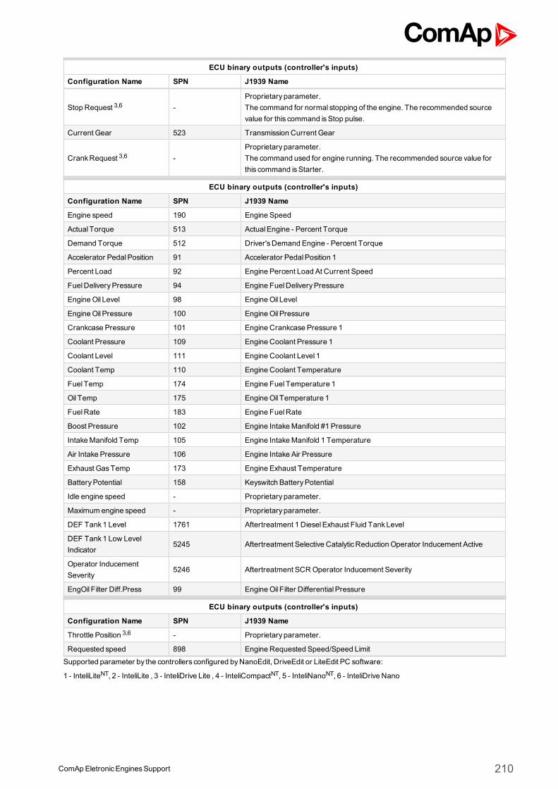
ComApEletronicEnginesSupport 210
ECU binary outputs (controller's inputs)
Configuration Name SPN J1939 Name
Stop Request 3,6 -Proprietary parameter.The command for normal stopping of the engine. The recommended sourcevalue for this command isStop pulse.
Current Gear 523 Transmission Current Gear
CrankRequest 3,6 -Proprietary parameter.The command used for engine running. The recommended source value forthis command isStarter.
ECU binary outputs (controller's inputs)
Configuration Name SPN J1939 Name
Engine speed 190 Engine Speed
Actual Torque 513 ActualEngine - Percent Torque
Demand Torque 512 Driver'sDemand Engine - Percent Torque
Accelerator PedalPosition 91 Accelerator PedalPosition 1
Percent Load 92 Engine Percent Load At Current Speed
FuelDeliveryPressure 94 Engine FuelDeliveryPressure
EngineOil Level 98 EngineOil Level
EngineOil Pressure 100 EngineOil Pressure
Crankcase Pressure 101 Engine Crankcase Pressure 1
Coolant Pressure 109 Engine Coolant Pressure 1
Coolant Level 111 Engine Coolant Level 1
Coolant Temp 110 Engine Coolant Temperature
Fuel Temp 174 Engine Fuel Temperature 1
Oil Temp 175 EngineOil Temperature 1
FuelRate 183 Engine FuelRate
Boost Pressure 102 Engine IntakeManifold #1 Pressure
IntakeManifold Temp 105 Engine IntakeManifold 1 Temperature
Air Intake Pressure 106 Engine Intake Air Pressure
Exhaust GasTemp 173 Engine Exhaust Temperature
BatteryPotential 158 Keyswitch BatteryPotential
Idle engine speed - Proprietary parameter.
Maximum engine speed - Proprietary parameter.
DEF Tank1 Level 1761 Aftertreatment 1 DieselExhaust Fluid TankLevel
DEF Tank1 Low LevelIndicator
5245 Aftertreatment Selective CatalyticReduction Operator Inducement Active
Operator InducementSeverity
5246 Aftertreatment SCROperator Inducement Severity
EngOil Filter Diff.Press 99 EngineOil Filter Differential Pressure
ECU binary outputs (controller's inputs)
Configuration Name SPN J1939 Name
Throttle Position 3,6 - Proprietary parameter.
Requested speed 898 Engine Requested Speed/Speed Limit
Supported parameter by the controllers configured byNanoEdit, DriveEdit or LiteEdit PC software:
1 - InteliLiteNT, 2 - InteliLite , 3 - InteliDrive Lite , 4 - InteliCompactNT, 5 - InteliNanoNT, 6 - InteliDrive Nano
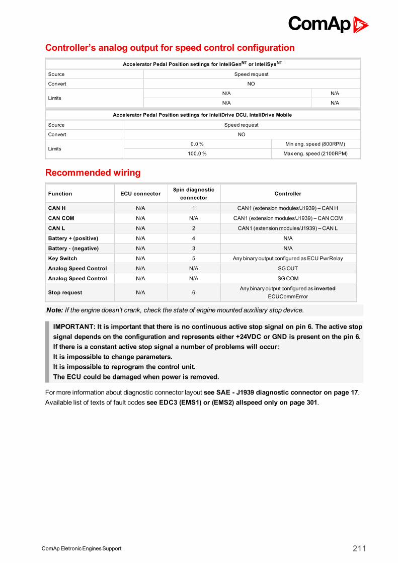
ComApEletronicEnginesSupport 211
Controller’s analog output for speed control configurationAccelerator Pedal Position settings for InteliGenNT or InteliSysNT
Source Speed request
Convert NO
LimitsN/A N/A
N/A N/A
Accelerator Pedal Position settings for InteliDrive DCU, InteliDrive Mobile
Source Speed request
Convert NO
Limits0.0 % Min eng. speed (800RPM)
100.0 % Max eng. speed (2100RPM)
Recommended wiring
Function ECU connector8pin diagnostic
connectorController
CAN H N/A 1 CAN1 (extensionmodules/J1939) – CAN H
CAN COM N/A N/A CAN1 (extensionmodules/J1939) – CAN COM
CAN L N/A 2 CAN1 (extensionmodules/J1939) – CAN L
Battery + (positive) N/A 4 N/A
Battery - (negative) N/A 3 N/A
Key Switch N/A 5 Anybinary output configured asECU PwrRelay
Analog Speed Control N/A N/A SGOUT
Analog Speed Control N/A N/A SGCOM
Stop request N/A 6Anybinary output configured as inverted
ECUCommError
Note: If the engine doesn't crank, check the state of enginemounted auxiliary stop device.
IMPORTANT: It is important that there is no continuous active stop signal on pin 6. The active stopsignal depends on the configuration and represents either +24VDC or GND is present on the pin 6.If there is a constant active stop signal a number of problems will occur:It is impossible to change parameters.It is impossible to reprogram the control unit.The ECU could be damaged when power is removed.
Formore information about diagnostic connector layout see SAE - J1939 diagnostic connector on page 17.Available list of texts of fault codes see EDC3 (EMS1) or (EMS2) allspeed only on page 301.
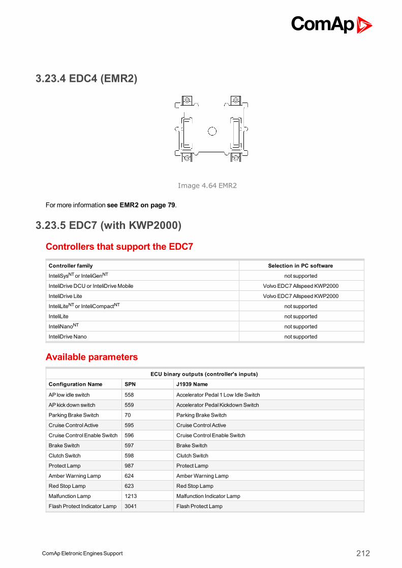
ComApEletronicEnginesSupport 212
3.23.4 EDC4 (EMR2)
Image 4.64 EMR2
Formore information see EMR2 on page 79.
3.23.5 EDC7 (with KWP2000)
Controllers that support the EDC7
Controller family Selection in PC software
InteliSysNTor InteliGenNT not supported
InteliDrive DCU or InteliDriveMobile Volvo EDC7Allspeed KWP2000
InteliDrive Lite Volvo EDC7Allspeed KWP2000
InteliLiteNTor InteliCompactNT not supported
InteliLite not supported
InteliNanoNT not supported
InteliDrive Nano not supported
Available parametersECU binary outputs (controller's inputs)
Configuration Name SPN J1939 Name
AP low idle switch 558 Accelerator Pedal 1 Low Idle Switch
AP kick down switch 559 Accelerator PedalKickdown Switch
Parking Brake Switch 70 Parking Brake Switch
Cruise Control Active 595 Cruise Control Active
Cruise Control Enable Switch 596 Cruise Control Enable Switch
Brake Switch 597 Brake Switch
Clutch Switch 598 Clutch Switch
Protect Lamp 987 Protect Lamp
Amber Warning Lamp 624 Amber Warning Lamp
Red Stop Lamp 623 Red Stop Lamp
Malfunction Lamp 1213 Malfunction Indicator Lamp
Flash Protect Indicator Lamp 3041 Flash Protect Lamp
ComApEletronicEnginesSupport 213
Flash Amber Warning Lamp
3040 Flash Amber Warning Lamp (AWL)Fast Flash Amber WarningLamp
Flash Red Stop Lamp3039 Flash Red Stop Lamp (RSL)
Fast Flash Red Stop Lamp
Running Indication - Proprietary parameter.
Diagnostic state - Proprietary parameter.
Oil Pressure Alarm - Proprietary parameter.
Oil Temperature Alarm - Proprietary parameter.
Oil LevelAlarm - Proprietary parameter.
Charge Alarm - Proprietary parameter.
Coolant Temperature - Proprietary parameter.
Coolant LevelAlarm - Proprietary parameter.
Water in FuelAlarm - Proprietary parameter.
Shift In Process 574 Transmission Shift In Process
Converter Lockup 573 Transmission Torque Converter Lockup Engaged
Momentary engineoverspeed enable
161 Transmission Input Shaft Speed
ECU binary outputs (controller's inputs)
Configuration Name SPN J1939 Name
CrankRequest - Proprietary parameter.
Stop Request - Proprietary parameter.
Current Gear 523 Transmission Current Gear
ECU binary outputs (controller's inputs)
Configuration Name SPN J1939 Name
Engine TorqueMode 899 Engine TorqueMode
Engine speed 190 Engine Speed
Actual Torque 513 ActualEngine - Percent Torque
Demand Torque 512 Driver'sDemand Engine - Percent Torque
Accelerator PedalPosition 91 Accelerator PedalPosition 1
Percent Load 92 Engine Percent Load At Current Speed
Nominal Friction Torque 514 Nominal Friction - Percent Torque
Cruise control set speed 86 Cruise Control Set Speed
Coolant Temp 110 Engine Coolant Temperature
Fuel Temp 174 Engine Fuel Temperature 1
BarometricPressure 108 BarometricPressure
Boost Pressure 102 Engine IntakeManifold #1 Pressure
IntakeManifold Temp 105 Engine IntakeManifold 1 Temperature
EngineOil Level 98 EngineOil Level
EngineOil Pressure 100 EngineOil Pressure
Crankcase Pressure 101 Engine Crankcase Pressure 1
FuelRate 183 Engine FuelRate
BatteryPotential 158 Keyswitch BatteryPotential
CommonRail Pressure - Proprietary parameter.
Out Shaft Speed 191 TransmissionOutput Shaft Speed
ComApEletronicEnginesSupport 214
ECU binary outputs (controller's inputs)
Configuration Name SPN J1939 Name
Throttle Position - Proprietary parameter.
Requested speed 898 Engine Requested Speed/Speed Limit
Torque Limit 518 Engine Requested Torque/Torque Limit
Controller’s analog output for speed control configurationRequested speed settings for InteliGenNT or InteliSysNT
Source SpeedReq RPM
Convert NO
LimitsN/A N/A
N/A N/A
Requested speed settings for InteliDrive DCU, InteliDrive Mobile
Source SpeedReq RPM
Convert NO
Limits0.0 % Min eng. speed (800RPM)
100.0 % Max eng. speed (2100RPM)
Recommended wiring
Formore information about diagnostic connector layout see SAE - J1939 diagnostic connector on page 17.Available list of texts of fault codes see EDC7 (with KWP2000) on page 302.
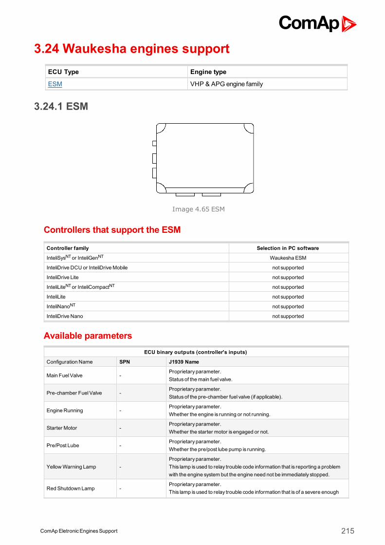
ComApEletronicEnginesSupport 215
3.24 Waukesha engines supportECU Type Engine type
ESM VHP & APG engine family
3.24.1 ESM
Image 4.65 ESM
Controllers that support the ESM
Controller family Selection in PC software
InteliSysNTor InteliGenNT Waukesha ESM
InteliDrive DCU or InteliDriveMobile not supported
InteliDrive Lite not supported
InteliLiteNTor InteliCompactNT not supported
InteliLite not supported
InteliNanoNT not supported
InteliDrive Nano not supported
Available parametersECU binary outputs (controller's inputs)
Configuration Name SPN J1939 Name
Main FuelValve -Proprietary parameter.Statusof themain fuel valve.
Pre-chamber FuelValve -Proprietary parameter.Statusof the pre-chamber fuel valve (if applicable).
Engine Running -Proprietary parameter.Whether the engine is running or not running.
Starter Motor -Proprietary parameter.Whether the starter motor is engaged or not.
Pre/Post Lube -Proprietary parameter.Whether the pre/post lube pump is running.
YellowWarning Lamp -Proprietary parameter.This lamp is used to relay trouble code information that is reporting a problemwith the engine system but the engine need not be immediately stopped.
Red Shutdown Lamp -Proprietary parameter.This lamp is used to relay trouble code information that is of a severe enough
ComApEletronicEnginesSupport 216
condition that it warrants stopping the engine.
Engine Knocking -Proprietary parameter.Whether the engine is in uncontrollable knock.
Start Engine Signal -Proprietary parameter.Whether the start engine signal is active.
NormalShutdown -Proprietary parameter.Whether the normal shutdown signal is active.
EmergencyShutdown -Proprietary parameter.Whether the emergency shutdown signal is active.
Remote rpmSelect -Proprietary parameter.Whether the remote rpm analog input is active or inactive.
Run High Idle -Proprietary parameter.Whether the run high idle digital input is active.
Alter Dynamics/Synchr Mode -Proprietary parameter.Whether the alternate governor dynamics is active.
Lockout Button/Ignit Module -Proprietary parameter.Whether either the lockout button hasbeen depressed or the IPM-D has failed,or is not powered.
ECU binary outputs (controller's inputs)
Configuration Name SPN J1939 Name
ECU binary outputs (controller's inputs)
Configuration Name SPN J1939 Name
Engine Speed -Proprietary parameter.Actual engine speed which is calculated over aminimum crankshaft angle of720 degreesdivided by the number of cylinders.
Oil Pressure -Proprietary parameter.Gage pressure of oil in engine lubrication system asprovided byoil pump.
IntakeManifold Press -
Proprietary parameter.Gage pressure of air measured downstream on the compressor dischargeside of the turbocharger. If there is one boost pressure to report and this rangeand resolution is adequate, this parameter should be used.
Throttle Position -
Proprietary parameter.The ratio of actual position of the analog engine speed/torque request inputdevice to themaximum position of the input device. This parameter is intendedfor the primary accelerator control in an application.
Coolant Temp -Proprietary parameter.Temperature of liquid found in engine cooling system.
BatteryVoltage -Proprietary parameter.Electrical potentialmeasured at the input of the electronic control unit suppliedthrough a switching device.
IntakeManifold Temp -Proprietary parameter.Temperature of pre-combustion air found in intakemanifold of engine airsupply system.
EngineOil Temp -Proprietary parameter.Temperature of the engine lubricant.
First exhaust temperature -Proprietary parameter.For more information about this commands, please contact localWaukesharepresentative.
Second exhaust temperature -Proprietary parameter.For more information about this commands, please contact localWaukesharepresentative.
ECU binary outputs (controller's inputs)
Configuration Name SPN J1939 Name
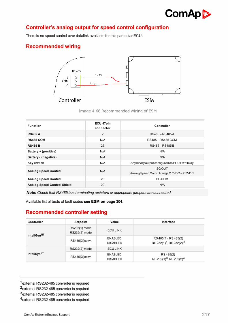
ComApEletronicEnginesSupport 217
Controller’s analog output for speed control configurationThere is no speed control over datalink available for this particular ECU.
Recommended wiring
Image 4.66 Recommended wiring of ESM
FunctionECU 47pinconnector
Controller
RS485 A 2 RS485 – RS485 A
RS485 COM N/A RS485 – RS485COM
RS485 B 23 RS485 – RS485 B
Battery + (positive) N/A N/A
Battery - (negative) N/A N/A
Key Switch N/A Anybinary output configured asECU PwrRelay
Analog Speed Control N/ASGOUT
Analog Speed Control range 2.5VDC – 7.5VDC
Analog Speed Control 28 SGCOM
Analog Speed Control Shield 29 N/A
Note: Check that RS485 bus terminating resistors or appropriate jumpers are connected.
Available list of texts of fault codes see ESM on page 304.
Recommended controller settingController Setpoint Value Interface
InteliGenNT
RS232(1) modeRS232(2) mode
ECU LINK
RS485(X)conv.ENABLEDDISABLED
RS485(1), RS 485(2)RS 232(1)1, RS 232(2) 2
InteliSysNTRS232(2) mode ECU LINK
RS485(X)conv.ENABLEDDISABLED
RS485(2)RS 232(1)3, RS 232(2)4
1external RS232-485 converter is required2external RS232-485 converter is required3external RS232-485 converter is required4external RS232-485 converter is required
ComApEletronicEnginesSupport 218
Waukesha wiring recommendationsTwomodbus wires are available at the end of the Customer Interface Harness (loose wires). The two wires aregrey and labeled RS 485A- and RS 485B+.
RS-485 networking needs termination resistors if long wire runs are used. Termination resistors of 120areplaced across the RS-485 A- and B+ wires at each device and at theMODBUS master ( InteliGenNT,InteliSysNTcontrollers has jumper connecting this resistor closed as default). For short distances of 10m orless and with slower baud rates (ComAp uses 9600 bps), termination resistors are not needed.
Typically, short distances of 32 ft. (10m) would not require termination resistors; however, if you experiencecommunication errors, first check the programmed baud rate. ComAp uses 9600 bps which is Waukeshadefault setting. If communication errors persist, termination resistors may be necessary even for shortdistances.
Diagnostic lampsIt is possible to configure Yellow Warning Lamp and Red Shutdown Lamp as binary inputs. Displaying of faultcodes in the alarm list is conditioned by configuration of these inputs. Once they are not configured the alarmsare blocked and not displayed.
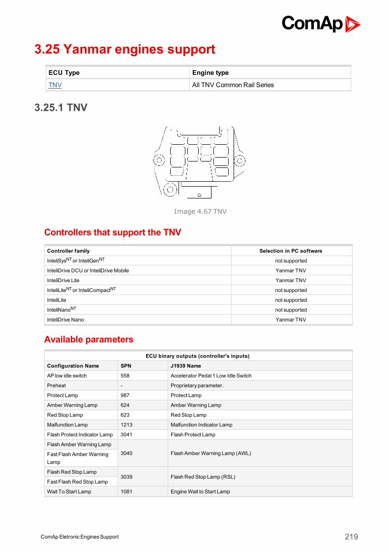
ComApEletronicEnginesSupport 219
3.25 Yanmar engines supportECU Type Engine type
TNV All TNV CommonRail Series
3.25.1 TNV
Image 4.67 TNV
Controllers that support the TNV
Controller family Selection in PC software
InteliSysNTor InteliGenNT not supported
InteliDrive DCU or InteliDriveMobile Yanmar TNV
InteliDrive Lite Yanmar TNV
InteliLiteNTor InteliCompactNT not supported
InteliLite not supported
InteliNanoNT not supported
InteliDrive Nano Yanmar TNV
Available parametersECU binary outputs (controller's inputs)
Configuration Name SPN J1939 Name
AP low idle switch 558 Accelerator Pedal 1 Low Idle Switch
Preheat - Proprietary parameter.
Protect Lamp 987 Protect Lamp
Amber Warning Lamp 624 Amber Warning Lamp
Red Stop Lamp 623 Red Stop Lamp
Malfunction Lamp 1213 Malfunction Indicator Lamp
Flash Protect Indicator Lamp 3041 Flash Protect Lamp
Flash Amber Warning Lamp
3040 Flash Amber Warning Lamp (AWL)Fast Flash Amber WarningLamp
Flash Red Stop Lamp3039 Flash Red Stop Lamp (RSL)
Fast Flash Red Stop Lamp
Wait To Start Lamp 1081 EngineWait to Start Lamp
ComApEletronicEnginesSupport 220
ECU binary outputs (controller's inputs)
Configuration Name SPN J1939 Name
ShutdownRequests - Proprietary parameter.
ECU binary outputs (controller's inputs)
Configuration Name SPN J1939 Name
Engine speed 190 Engine Speed
Starter mode 1675 Engine Starter Mode
APPosition 91 Accelerator PedalPosition 1
Percent Load 92 Engine Percent Load At Current Speed
ECU Temperature 1136 Engine ECU Temperature
Desired Operating Speed 515 Engine'sDesired Operating Speed
Coolant Temp 110 Engine Coolant Temperature
Oil Temp 175 EngineOil Temperature 1
BarometricPressure 108 BarometricPressure
Air Inlet Temperature 172 Engine Intake Air Temperature
ElectricalPotential 168 BatteryPotential / Power Input 1
BatteryPotential (Voltage) 158 Keyswitch BatteryPotential
EngineOil Pressure 100 EngineOil Pressure
ECU binary outputs (controller's inputs)
Configuration Name SPN J1939 Name
Requested speed 3,6 898 Engine Requested Speed/Speed Limit
Accelerator PedalPosition - Proprietary parameter.
Supported parameter by the controllers configured byNanoEdit, DriveEdit or LiteEdit PC software:
1 - InteliLiteNT, 2 - InteliLite , 3 - InteliDrive Lite , 4 - InteliCompactNT, 5 - InteliNanoNT, 6 - InteliDrive Nano
Controller’s analog output for speed control configurationRequested speed settings for InteliGenNT or InteliSysNT
Source SpeedReq RPM
Convert NO
LimitsN/A N/A
N/A N/A
Requested speed settings for InteliDrive DCU, InteliDrive Mobile
Source SpeedReq RPM
Convert NO
Limits0.0 % Min eng. speed (800RPM)
100.0 % Max eng. speed (2100RPM)
Recommended wiringFunction ECU connector Controller
CAN H 40 CAN1 (extension modules/J1939) – CANH
CAN COM 30 CAN1 (extensionmodules/J1939) – CAN COM
CAN L 39 CAN1 (extension modules/J1939) – CANL
Battery + (positive) 34 N/A
Battery - (negative) 33,45 N/A

ComApEletronicEnginesSupport 221
Key Switch 7 Anybinary output configured asECU PwrRelay
Analog Speed Control N/A SG OUT
Analog Speed Control N/A SGCOM
Formore information about diagnostic connector layout see SAE - J1939 diagnostic connector on page 17.Available list of texts of fault codes see TNV on page 305.
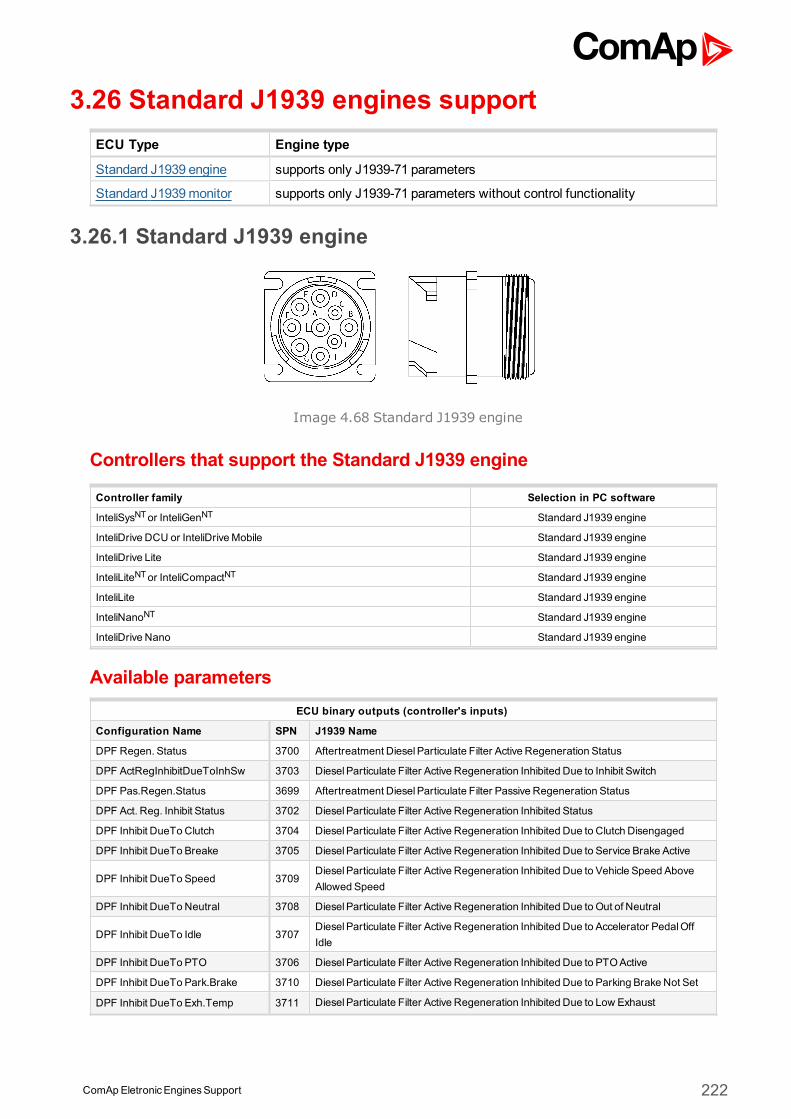
ComApEletronicEnginesSupport 222
3.26 Standard J1939 engines supportECU Type Engine type
Standard J1939 engine supports only J1939-71 parameters
Standard J1939monitor supports only J1939-71 parameters without control functionality
3.26.1 Standard J1939 engine
Image 4.68 Standard J1939 engine
Controllers that support the Standard J1939 engine
Controller family Selection in PC software
InteliSysNTor InteliGenNT Standard J1939 engine
InteliDrive DCU or InteliDriveMobile Standard J1939 engine
InteliDrive Lite Standard J1939 engine
InteliLiteNTor InteliCompactNT Standard J1939 engine
InteliLite Standard J1939 engine
InteliNanoNT Standard J1939 engine
InteliDrive Nano Standard J1939 engine
Available parametersECU binary outputs (controller's inputs)
Configuration Name SPN J1939 Name
DPF Regen. Status 3700 Aftertreatment DieselParticulate Filter Active Regeneration Status
DPF ActRegInhibitDueToInhSw 3703 DieselParticulate Filter Active Regeneration Inhibited Due to Inhibit Switch
DPF Pas.Regen.Status 3699 Aftertreatment DieselParticulate Filter Passive Regeneration Status
DPF Act. Reg. Inhibit Status 3702 DieselParticulate Filter Active Regeneration Inhibited Status
DPF Inhibit DueToClutch 3704 DieselParticulate Filter Active Regeneration Inhibited Due to Clutch Disengaged
DPF Inhibit DueTo Breake 3705 DieselParticulate Filter Active Regeneration Inhibited Due to Service Brake Active
DPF Inhibit DueTo Speed 3709DieselParticulate Filter Active Regeneration Inhibited Due to Vehicle Speed AboveAllowed Speed
DPF Inhibit DueToNeutral 3708 DieselParticulate Filter Active Regeneration Inhibited Due to Out of Neutral
DPF Inhibit DueTo Idle 3707DieselParticulate Filter Active Regeneration Inhibited Due to Accelerator PedalOffIdle
DPF Inhibit DueTo PTO 3706 DieselParticulate Filter Active Regeneration Inhibited Due to PTOActive
DPF Inhibit DueTo Park.Brake 3710 DieselParticulate Filter Active Regeneration Inhibited Due to Parking Brake Not Set
DPF Inhibit DueTo Exh.Temp 3711 DieselParticulate Filter Active Regeneration Inhibited Due to Low Exhaust
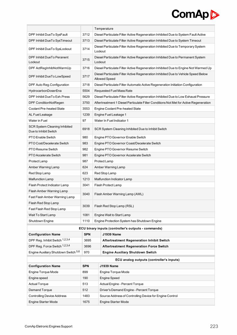
ComApEletronicEnginesSupport 223
Temperature
DPF Inhibit DueTo SysFault 3712 DieselParticulate Filter Active Regeneration Inhibited Due to System Fault Active
DPF Inhibit DueTo SysTimeout 3713 DieselParticulate Filter Active Regeneration Inhibited Due to System Timeout
DPF Inhibit DueTo SysLockout 3714DieselParticulate Filter Active Regeneration Inhibited Due to TemporarySystemLockout
DPF Inhibit DueTo PeranentLockout
3715DieselParticulate Filter Active Regeneration Inhibited Due to Permanent SystemLockout
DPF ActRegInhibNotWarmUp 3716 DieselParticulate Filter Active Regeneration Inhibited Due to Engine NotWarmedUp
DPF Inhibit DueTo LowSpeed 3717DieselParticulate Filter Active Regeneration Inhibited Due to Vehicle Speed BelowAllowed Speed
DPF Auto Reg.Configuration 3718 DieselParticulate Filter AutomaticActive Regeneration Initiation Configuration
HydrocarbonDoserEna 5504 Requested FuelMassRate
DPF Inhibit DueTo Exh.Press 5629 DieselParticulate Filter Active Regeneration Inhibited Due to Low Exhaust Pressure
DPF ConditionNotRegen 3750 Aftertreatment 1 DieselParticulate Filter ConditionsNot Met for Active Regeneration
Coolant Pre-heated State 3553 Engine Coolant Pre-heated State
AL Fuel Leakage 1239 Engine Fuel Leakage 1
Water in Fuel 97 Water In Fuel Indicator 1
SCR SystemCleaning InhibitedDue to Inhibit Switch
6918 SCR SystemCleaning Inhibited Due to Inhibit Switch
PTOEnable Switch 980 Engine PTOGovernor Enable Switch
PTOCost/Decelerate Switch 983 Engine PTOGovernor Coast/Decelerate Switch
PTOResumeSwitch 982 Engine PTOGovernor ResumeSwitch
PTOAccelerate Switch 981 Engine PTOGovernor Accelerate Switch
Protect Lamp 987 Protect Lamp
Amber Warning Lamp 624 Amber Warning Lamp
Red Stop Lamp 623 Red Stop Lamp
Malfunction Lamp 1213 Malfunction Indicator Lamp
Flash Protect Indicator Lamp 3041 Flash Protect Lamp
Flash Amber Warning Lamp3040 Flash Amber Warning Lamp (AWL)
Fast Flash Amber Warning Lamp
Flash Red Stop Lamp3039 Flash Red Stop Lamp (RSL)
Fast Flash Red Stop Lamp
Wait To Start Lamp 1081 EngineWait to Start Lamp
Shutdown Engine 1110 Engine Protection System hasShutdown Engine
ECU binary inputs (controller's outputs - commands)
Configuration Name SPN J1939 Name
DPF Reg. Inhibit Switch 1,2,3,4 3695 Aftertreatment Regeneration Inhibit Switch
DPF Reg. Force Switch 1,2,3,4 3696 Aftertreatment Regeneration Force Switch
Engine AuxiliaryShutdown Switch 5,6 970 Engine Auxiliary Shutdown Switch
ECU analog outputs (controller's inputs)
Configuration Name SPN J1939 Name
Engine TorqueMode 899 Engine TorqueMode
Engine speed 190 Engine Speed
Actual Torque 513 ActualEngine - Percent Torque
Demand Torque 512 Driver'sDemand Engine - Percent Torque
Controlling Device Address 1483 Source Addressof Controlling Device for Engine Control
Engine Starter Mode 1675 Engine Starter Mode
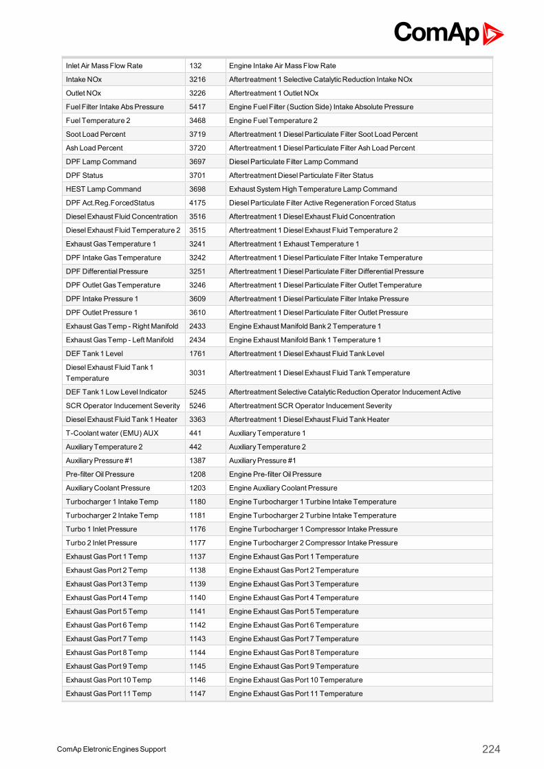
ComApEletronicEnginesSupport 224
Inlet Air MassFlow Rate 132 Engine Intake Air MassFlow Rate
Intake NOx 3216 Aftertreatment 1 Selective CatalyticReduction Intake NOx
Outlet NOx 3226 Aftertreatment 1 Outlet NOx
Fuel Filter Intake AbsPressure 5417 Engine Fuel Filter (Suction Side) Intake Absolute Pressure
Fuel Temperature 2 3468 Engine Fuel Temperature 2
Soot Load Percent 3719 Aftertreatment 1 DieselParticulate Filter Soot Load Percent
Ash Load Percent 3720 Aftertreatment 1 DieselParticulate Filter Ash Load Percent
DPF LampCommand 3697 DieselParticulate Filter LampCommand
DPF Status 3701 Aftertreatment DieselParticulate Filter Status
HEST LampCommand 3698 Exhaust SystemHigh Temperature LampCommand
DPF Act.Reg.ForcedStatus 4175 DieselParticulate Filter Active Regeneration Forced Status
DieselExhaust Fluid Concentration 3516 Aftertreatment 1 DieselExhaust Fluid Concentration
DieselExhaust Fluid Temperature 2 3515 Aftertreatment 1 DieselExhaust Fluid Temperature 2
Exhaust GasTemperature 1 3241 Aftertreatment 1 Exhaust Temperature 1
DPF IntakeGasTemperature 3242 Aftertreatment 1 DieselParticulate Filter Intake Temperature
DPF Differential Pressure 3251 Aftertreatment 1 DieselParticulate Filter Differential Pressure
DPF Outlet GasTemperature 3246 Aftertreatment 1 DieselParticulate Filter Outlet Temperature
DPF Intake Pressure 1 3609 Aftertreatment 1 DieselParticulate Filter Intake Pressure
DPF Outlet Pressure 1 3610 Aftertreatment 1 DieselParticulate Filter Outlet Pressure
Exhaust GasTemp - Right Manifold 2433 Engine Exhaust Manifold Bank2 Temperature 1
Exhaust GasTemp - Left Manifold 2434 Engine Exhaust Manifold Bank1 Temperature 1
DEF Tank1 Level 1761 Aftertreatment 1 DieselExhaust Fluid TankLevel
DieselExhaust Fluid Tank1Temperature
3031 Aftertreatment 1 DieselExhaust Fluid TankTemperature
DEF Tank1 Low Level Indicator 5245 Aftertreatment Selective CatalyticReduction Operator Inducement Active
SCROperator Inducement Severity 5246 Aftertreatment SCROperator Inducement Severity
DieselExhaust Fluid Tank1 Heater 3363 Aftertreatment 1 DieselExhaust Fluid TankHeater
T-Coolant water (EMU) AUX 441 AuxiliaryTemperature 1
AuxiliaryTemperature 2 442 AuxiliaryTemperature 2
AuxiliaryPressure #1 1387 AuxiliaryPressure #1
Pre-filter Oil Pressure 1208 Engine Pre-filter Oil Pressure
AuxiliaryCoolant Pressure 1203 Engine AuxiliaryCoolant Pressure
Turbocharger 1 Intake Temp 1180 Engine Turbocharger 1 Turbine Intake Temperature
Turbocharger 2 Intake Temp 1181 Engine Turbocharger 2 Turbine Intake Temperature
Turbo 1 Inlet Pressure 1176 Engine Turbocharger 1 Compressor Intake Pressure
Turbo 2 Inlet Pressure 1177 Engine Turbocharger 2 Compressor Intake Pressure
Exhaust GasPort 1 Temp 1137 Engine Exhaust GasPort 1 Temperature
Exhaust GasPort 2 Temp 1138 Engine Exhaust GasPort 2 Temperature
Exhaust GasPort 3 Temp 1139 Engine Exhaust GasPort 3 Temperature
Exhaust GasPort 4 Temp 1140 Engine Exhaust GasPort 4 Temperature
Exhaust GasPort 5 Temp 1141 Engine Exhaust GasPort 5 Temperature
Exhaust GasPort 6 Temp 1142 Engine Exhaust GasPort 6 Temperature
Exhaust GasPort 7 Temp 1143 Engine Exhaust GasPort 7 Temperature
Exhaust GasPort 8 Temp 1144 Engine Exhaust GasPort 8 Temperature
Exhaust GasPort 9 Temp 1145 Engine Exhaust GasPort 9 Temperature
Exhaust GasPort 10 Temp 1146 Engine Exhaust GasPort 10 Temperature
Exhaust GasPort 11 Temp 1147 Engine Exhaust GasPort 11 Temperature
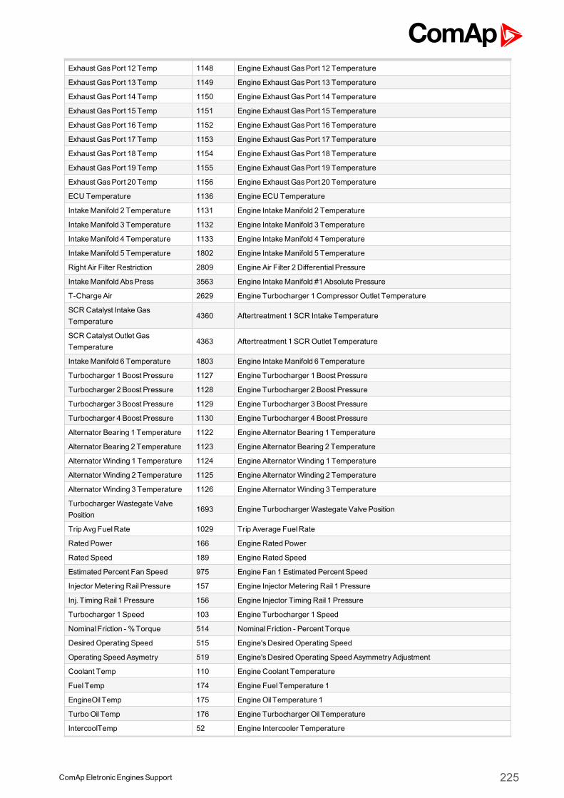
ComApEletronicEnginesSupport 225
Exhaust GasPort 12 Temp 1148 Engine Exhaust GasPort 12 Temperature
Exhaust GasPort 13 Temp 1149 Engine Exhaust GasPort 13 Temperature
Exhaust GasPort 14 Temp 1150 Engine Exhaust GasPort 14 Temperature
Exhaust GasPort 15 Temp 1151 Engine Exhaust GasPort 15 Temperature
Exhaust GasPort 16 Temp 1152 Engine Exhaust GasPort 16 Temperature
Exhaust GasPort 17 Temp 1153 Engine Exhaust GasPort 17 Temperature
Exhaust GasPort 18 Temp 1154 Engine Exhaust GasPort 18 Temperature
Exhaust GasPort 19 Temp 1155 Engine Exhaust GasPort 19 Temperature
Exhaust GasPort 20 Temp 1156 Engine Exhaust GasPort 20 Temperature
ECU Temperature 1136 Engine ECU Temperature
IntakeManifold 2 Temperature 1131 Engine IntakeManifold 2 Temperature
IntakeManifold 3 Temperature 1132 Engine IntakeManifold 3 Temperature
IntakeManifold 4 Temperature 1133 Engine IntakeManifold 4 Temperature
IntakeManifold 5 Temperature 1802 Engine IntakeManifold 5 Temperature
Right Air Filter Restriction 2809 Engine Air Filter 2 Differential Pressure
IntakeManifold AbsPress 3563 Engine IntakeManifold #1 Absolute Pressure
T-Charge Air 2629 Engine Turbocharger 1 Compressor Outlet Temperature
SCR Catalyst IntakeGasTemperature
4360 Aftertreatment 1 SCR Intake Temperature
SCR Catalyst Outlet GasTemperature
4363 Aftertreatment 1 SCROutlet Temperature
IntakeManifold 6 Temperature 1803 Engine IntakeManifold 6 Temperature
Turbocharger 1 Boost Pressure 1127 Engine Turbocharger 1 Boost Pressure
Turbocharger 2 Boost Pressure 1128 Engine Turbocharger 2 Boost Pressure
Turbocharger 3 Boost Pressure 1129 Engine Turbocharger 3 Boost Pressure
Turbocharger 4 Boost Pressure 1130 Engine Turbocharger 4 Boost Pressure
Alternator Bearing 1 Temperature 1122 Engine Alternator Bearing 1 Temperature
Alternator Bearing 2 Temperature 1123 Engine Alternator Bearing 2 Temperature
Alternator Winding 1 Temperature 1124 Engine Alternator Winding 1 Temperature
Alternator Winding 2 Temperature 1125 Engine Alternator Winding 2 Temperature
Alternator Winding 3 Temperature 1126 Engine Alternator Winding 3 Temperature
Turbocharger Wastegate ValvePosition
1693 Engine Turbocharger Wastegate Valve Position
Trip Avg FuelRate 1029 Trip Average FuelRate
Rated Power 166 Engine Rated Power
Rated Speed 189 Engine Rated Speed
Estimated Percent Fan Speed 975 Engine Fan 1 Estimated Percent Speed
Injector Metering Rail Pressure 157 Engine Injector Metering Rail 1 Pressure
Inj. Timing Rail 1 Pressure 156 Engine Injector Timing Rail 1 Pressure
Turbocharger 1 Speed 103 Engine Turbocharger 1 Speed
Nominal Friction - %Torque 514 Nominal Friction - Percent Torque
Desired Operating Speed 515 Engine'sDesired Operating Speed
Operating Speed Asymetry 519 Engine'sDesired Operating Speed AsymmetryAdjustment
Coolant Temp 110 Engine Coolant Temperature
Fuel Temp 174 Engine Fuel Temperature 1
EngineOil Temp 175 EngineOil Temperature 1
TurboOil Temp 176 Engine Turbocharger Oil Temperature
IntercoolTemp 52 Engine Intercooler Temperature
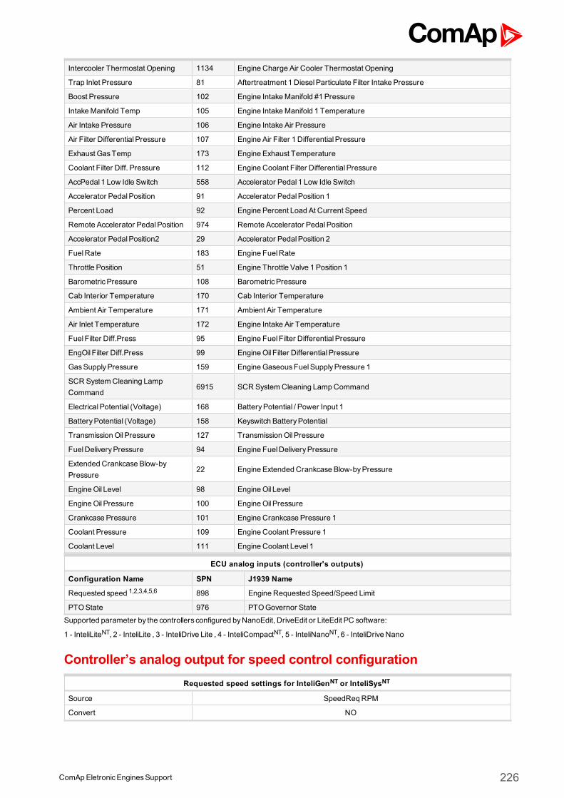
ComApEletronicEnginesSupport 226
Intercooler Thermostat Opening 1134 Engine Charge Air Cooler Thermostat Opening
Trap Inlet Pressure 81 Aftertreatment 1 DieselParticulate Filter Intake Pressure
Boost Pressure 102 Engine IntakeManifold #1 Pressure
IntakeManifold Temp 105 Engine IntakeManifold 1 Temperature
Air Intake Pressure 106 Engine Intake Air Pressure
Air Filter Differential Pressure 107 Engine Air Filter 1 Differential Pressure
Exhaust GasTemp 173 Engine Exhaust Temperature
Coolant Filter Diff. Pressure 112 Engine Coolant Filter Differential Pressure
AccPedal 1 Low Idle Switch 558 Accelerator Pedal 1 Low Idle Switch
Accelerator PedalPosition 91 Accelerator PedalPosition 1
Percent Load 92 Engine Percent Load At Current Speed
Remote Accelerator PedalPosition 974 Remote Accelerator PedalPosition
Accelerator PedalPosition2 29 Accelerator PedalPosition 2
FuelRate 183 Engine FuelRate
Throttle Position 51 Engine Throttle Valve 1 Position 1
BarometricPressure 108 BarometricPressure
Cab Interior Temperature 170 Cab Interior Temperature
Ambient Air Temperature 171 Ambient Air Temperature
Air Inlet Temperature 172 Engine Intake Air Temperature
Fuel Filter Diff.Press 95 Engine Fuel Filter Differential Pressure
EngOil Filter Diff.Press 99 EngineOil Filter Differential Pressure
GasSupplyPressure 159 EngineGaseousFuelSupplyPressure 1
SCR SystemCleaning LampCommand
6915 SCR SystemCleaning LampCommand
ElectricalPotential (Voltage) 168 BatteryPotential / Power Input 1
BatteryPotential (Voltage) 158 Keyswitch BatteryPotential
TransmissionOil Pressure 127 TransmissionOil Pressure
FuelDeliveryPressure 94 Engine FuelDeliveryPressure
Extended Crankcase Blow-byPressure
22 Engine Extended Crankcase Blow-byPressure
EngineOil Level 98 EngineOil Level
EngineOil Pressure 100 EngineOil Pressure
Crankcase Pressure 101 Engine Crankcase Pressure 1
Coolant Pressure 109 Engine Coolant Pressure 1
Coolant Level 111 Engine Coolant Level 1
ECU analog inputs (controller's outputs)
Configuration Name SPN J1939 Name
Requested speed 1,2,3,4,5,6 898 Engine Requested Speed/Speed Limit
PTOState 976 PTOGovernor State
Supported parameter by the controllers configured byNanoEdit, DriveEdit or LiteEdit PC software:
1 - InteliLiteNT, 2 - InteliLite , 3 - InteliDrive Lite , 4 - InteliCompactNT, 5 - InteliNanoNT, 6 - InteliDrive Nano
Controller’s analog output for speed control configurationRequested speed settings for InteliGenNT or InteliSysNT
Source SpeedReqRPM
Convert NO
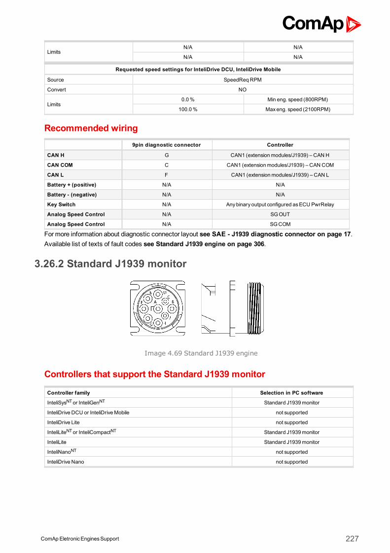
ComApEletronicEnginesSupport 227
LimitsN/A N/A
N/A N/A
Requested speed settings for InteliDrive DCU, InteliDrive Mobile
Source SpeedReqRPM
Convert NO
Limits0.0% Min eng. speed (800RPM)
100.0% Maxeng. speed (2100RPM)
Recommended wiring9pin diagnostic connector Controller
CAN H G CAN1 (extensionmodules/J1939) – CAN H
CAN COM C CAN1 (extensionmodules/J1939) – CAN COM
CAN L F CAN1 (extensionmodules/J1939) – CAN L
Battery + (positive) N/A N/A
Battery - (negative) N/A N/A
Key Switch N/A Anybinary output configured asECU PwrRelay
Analog Speed Control N/A SGOUT
Analog Speed Control N/A SGCOM
Formore information about diagnostic connector layout see SAE - J1939 diagnostic connector on page 17.Available list of texts of fault codes see Standard J1939 engine on page 306.
3.26.2 Standard J1939 monitor
Image 4.69 Standard J1939 engine
Controllers that support the Standard J1939 monitor
Controller family Selection in PC software
InteliSysNTor InteliGenNT Standard J1939monitor
InteliDrive DCU or InteliDriveMobile not supported
InteliDrive Lite not supported
InteliLiteNTor InteliCompactNT Standard J1939monitor
InteliLite Standard J1939monitor
InteliNanoNT not supported
InteliDrive Nano not supported
ComApEletronicEnginesSupport 228
Available parametersECU binary outputs (controller's inputs)
Configuration Name SPN J1939 Name
DPF Regen. Status 3700 Aftertreatment DieselParticulate Filter Active Regeneration Status
DPF ActRegInhibitDueToInhSw 3703 DieselParticulate Filter Active Regeneration Inhibited Due to Inhibit Switch
DPF Pas.Regen.Status 3699 Aftertreatment DieselParticulate Filter Passive Regeneration Status
DPF Act. Reg. Inhibit Status 3702 DieselParticulate Filter Active Regeneration Inhibited Status
DPF Inhibit DueToClutch 3704 DieselParticulate Filter Active Regeneration Inhibited Due to Clutch Disengaged
DPF Inhibit DueTo Breake 3705 DieselParticulate Filter Active Regeneration Inhibited Due to Service Brake Active
DPF Inhibit DueTo Speed 3709DieselParticulate Filter Active Regeneration Inhibited Due to Vehicle Speed AboveAllowed Speed
DPF Inhibit DueToNeutral 3708 DieselParticulate Filter Active Regeneration Inhibited Due to Out of Neutral
DPF Inhibit DueTo Idle 3707DieselParticulate Filter Active Regeneration Inhibited Due to Accelerator PedalOffIdle
DPF Inhibit DueTo PTO 3706 DieselParticulate Filter Active Regeneration Inhibited Due to PTOActive
DPF Inhibit DueTo Park.Brake 3710 DieselParticulate Filter Active Regeneration Inhibited Due to Parking Brake Not Set
DPF Inhibit DueTo Exh.Temp 3711DieselParticulate Filter Active Regeneration Inhibited Due to Low ExhaustTemperature
DPF Inhibit DueTo SysFault 3712 DieselParticulate Filter Active Regeneration Inhibited Due to System Fault Active
DPF Inhibit DueTo SysTimeout 3713 DieselParticulate Filter Active Regeneration Inhibited Due to System Timeout
DPF Inhibit DueTo SysLockout 3714DieselParticulate Filter Active Regeneration Inhibited Due to TemporarySystemLockout
DPF Inhibit DueTo PeranentLockout
3715DieselParticulate Filter Active Regeneration Inhibited Due to Permanent SystemLockout
DPF ActRegInhibNotWarmUp 3716 DieselParticulate Filter Active Regeneration Inhibited Due to Engine NotWarmedUp
DPF Inhibit DueTo LowSpeed 3717DieselParticulate Filter Active Regeneration Inhibited Due to Vehicle Speed BelowAllowed Speed
DPF Auto Reg.Configuration 3718 DieselParticulate Filter AutomaticActive Regeneration Initiation Configuration
HydrocarbonDoserEna 5504 Hydrocarbon Doser Purging Enable
DPF Inhibit DueTo Exh.Press 5629 DieselParticulate Filter Active Regeneration Inhibited Due to Low Exhaust Pressure
DPF ConditionNotRegen 3750 Aftertreatment 1 DieselParticulate Filter ConditionsNot Met for Active Regeneration
Coolant Pre-heated State 3553 Engine Coolant Pre-heated State
AL Fuel Leakage 1239 Engine Fuel Leakage 1
Water in Fuel 97 Water In Fuel Indicator 1
SCR SystemCleaning InhibitedDue to Inhibit Switch
6918 SCR SystemCleaning Inhibited Due to Inhibit Switch
PTOEnable Switch 980 Engine PTOGovernor Enable Switch
PTOCost/Decelerate Switch 983 Engine PTOGovernor Coast/Decelerate Switch
PTOResumeSwitch 982 Engine PTOGovernor ResumeSwitch
PTOAccelerate Switch 981 Engine PTOGovernor Accelerate Switch
Protect Lamp 987 Protect Lamp
Amber Warning Lamp 624 Amber Warning Lamp
Red Stop Lamp 623 Red Stop Lamp
Malfunction Lamp 1213 Malfunction Indicator Lamp
Flash Protect Indicator Lamp 3041 Flash Protect Lamp
Flash Amber Warning Lamp3040 Flash Amber Warning Lamp (AWL)
Fast Flash Amber Warning Lamp
ComApEletronicEnginesSupport 229
Flash Red Stop Lamp3039 Flash Red Stop Lamp (RSL)
Fast Flash Red Stop Lamp
Wait To Start Lamp 1081 EngineWait to Start Lamp
Shutdown Engine 1110 Engine Protection System hasShutdown Engine
DPF Reg. Inhibit Switch(RX) 3695 Aftertreatment Regeneration Inhibit Switch
DPF Reg. Force Switch(RX) 3696 Aftertreatment Regeneration Force Switch
Engine AuxiliaryShutdown Sw(RX) 970 Engine AuxiliaryShutdown Switch
ECU binary inputs (controller's outputs - commands)
Configuration Name SPN J1939 Name
ECU analog outputs (controller's inputs)
Configuration Name SPN J1939 Name
Engine TorqueMode 899 Engine TorqueMode
Engine speed 190 Engine Speed
Actual Torque 513 ActualEngine - Percent Torque
Demand Torque 512 Driver'sDemand Engine - Percent Torque
Coolant Pressure 109 Engine Coolant Pressure 1
Coolant Level 111 Engine Coolant Level 1
Override controlmode(RX) 695 EngineOverride ControlMode
Req Speed CtrlConditions(RX) 696 Engine Requested Speed ControlConditions
Override ControlMode Prior(RX) 897 Override ControlMode Priority
Requested speed(RX) 898 Engine Requested Speed/Speed Limit
Intake NOx 3216 Aftertreatment 1 Selective CatalyticReduction Intake NOx
Outlet NOx 3226 Aftertreatment 1 Outlet NOx
Fuel Filter Intake AbsPressure 5417 Engine Fuel Filter (Suction Side) Intake Absolute Pressure
Fuel Temperature 2 3468 Engine Fuel Temperature 2
Soot Load Percent 3719 Aftertreatment 1 DieselParticulate Filter Soot Load Percent
Ash Load Percent 3720 Aftertreatment 1 DieselParticulate Filter Ash Load Percent
DPF LampCommand 3697 DieselParticulate Filter LampCommand
DPF Status 3701 Aftertreatment DieselParticulate Filter Status
HEST LampCommand 3698 Exhaust SystemHigh Temperature LampCommand
DPF Act.Reg.ForcedStatus 4175 DieselParticulate Filter Active Regeneration Forced Status
DieselExhaust Fluid Concentration 3516 Aftertreatment 1 DieselExhaust Fluid Concentration
DieselExhaust Fluid Temperature 2 3515 Aftertreatment 1 DieselExhaust Fluid Temperature 2
Exhaust GasTemperature 1 3241 Aftertreatment 1 Exhaust Temperature 1
DPF IntakeGasTemperature 3242 Aftertreatment 1 DieselParticulate Filter Intake Temperature
DPF Differential Pressure 3251 Aftertreatment 1 DieselParticulate Filter Differential Pressure
DPF Outlet GasTemperature 3246 Aftertreatment 1 DieselParticulate Filter Outlet Temperature
DPF Intake Pressure 1 3609 Aftertreatment 1 DieselParticulate Filter Intake Pressure
DPF Outlet Pressure 1 3610 Aftertreatment 1 DieselParticulate Filter Outlet Pressure
Right Air Filter Restriction 2809 Engine Air Filter 2 Differential Pressure
IntakeManifold AbsPress 3563 Engine IntakeManifold #1 Absolute Pressure
T-Charge Air 2629 Engine Turbocharger 1 Compressor Outlet Temperature
SCR Catalyst IntakeGasTemperature
4360 Aftertreatment 1 SCR Intake Temperature
SCR Catalyst Outlet GasTemperature
4363 Aftertreatment 1 SCROutlet Temperature
Exhaust GasTemp - Right Manifold 2433 Engine Exhaust Manifold Bank2 Temperature 1
ComApEletronicEnginesSupport 230
Exhaust GasTemp - Left Manifold 2434 Engine Exhaust Manifold Bank1 Temperature 1
DEF Tank1 Level 1761 Aftertreatment 1 DieselExhaust Fluid TankLevel
DieselExhaust Fluid Tank1Temperature
3031 Aftertreatment 1 DieselExhaust Fluid TankTemperature
DEF Tank1 Low Level Indicator 5245 Aftertreatment Selective CatalyticReduction Operator Inducement Active
SCROperator Inducement Severity 5246 Aftertreatment SCROperator Inducement Severity
DieselExhaust Fluid Tank1 Heater 3363 Aftertreatment 1 DieselExhaust Fluid TankHeater
T-Coolant water (EMU) AUX 441 AuxiliaryTemperature 1
AuxiliaryTemperature 2 442 AuxiliaryTemperature 2
AuxiliaryPressure #1 1387 AuxiliaryPressure #1
Pre-filter Oil Pressure 1208 Engine Pre-filter Oil Pressure
AuxiliaryCoolant Pressure 1203 Engine AuxiliaryCoolant Pressure
Turbocharger 1 Intake Temp 1180 Engine Turbocharger 1 Turbine Intake Temperature
Turbocharger 2 Intake Temp 1181 Engine Turbocharger 2 Turbine Intake Temperature
Turbo 1 Inlet Pressure 1176 Engine Turbocharger 1 Compressor Intake Pressure
Turbo 2 Inlet Pressure 1177 Engine Turbocharger 2 Compressor Intake Pressure
Exhaust GasPort 1 Temp 1137 Engine Exhaust GasPort 1 Temperature
Exhaust GasPort 2 Temp 1138 Engine Exhaust GasPort 2 Temperature
Engine Starter Mode 1675 Engine Starter Mode
Inlet Air MassFlow Rate 132 Engine Intake Air MassFlow Rate
Exhaust GasPort 3 Temp 1139 Engine Exhaust GasPort 3 Temperature
Exhaust GasPort 4 Temp 1140 Engine Exhaust GasPort 4 Temperature
Exhaust GasPort 5 Temp 1141 Engine Exhaust GasPort 5 Temperature
Exhaust GasPort 6 Temp 1142 Engine Exhaust GasPort 6 Temperature
Exhaust GasPort 7 Temp 1143 Engine Exhaust GasPort 7 Temperature
Exhaust GasPort 8 Temp 1144 Engine Exhaust GasPort 8 Temperature
Exhaust GasPort 9 Temp 1145 Engine Exhaust GasPort 9 Temperature
Exhaust GasPort 10 Temp 1146 Engine Exhaust GasPort 10 Temperature
Exhaust GasPort 11 Temp 1147 Engine Exhaust GasPort 11 Temperature
Exhaust GasPort 12 Temp 1148 Engine Exhaust GasPort 12 Temperature
Exhaust GasPort 13 Temp 1149 Engine Exhaust GasPort 13 Temperature
Exhaust GasPort 14 Temp 1150 Engine Exhaust GasPort 14 Temperature
Exhaust GasPort 15 Temp 1151 Engine Exhaust GasPort 15 Temperature
Exhaust GasPort 16 Temp 1152 Engine Exhaust GasPort 16 Temperature
Exhaust GasPort 17 Temp 1153 Engine Exhaust GasPort 17 Temperature
Exhaust GasPort 18 Temp 1154 Engine Exhaust GasPort 18 Temperature
Exhaust GasPort 19 Temp 1155 Engine Exhaust GasPort 19 Temperature
Exhaust GasPort 20 Temp 1156 Engine Exhaust GasPort 20 Temperature
ECU Temperature 1136 Engine ECU Temperature
IntakeManifold 2 Temperature 1131 Engine IntakeManifold 2 Temperature
IntakeManifold 3 Temperature 1132 Engine IntakeManifold 3 Temperature
IntakeManifold 4 Temperature 1133 Engine IntakeManifold 4 Temperature
IntakeManifold 5 Temperature 1802 Engine IntakeManifold 5 Temperature
IntakeManifold 6 Temperature 1803 Engine IntakeManifold 6 Temperature
Turbocharger 1 Boost Pressure 1127 Engine Turbocharger 1 Boost Pressure
Turbocharger 2 Boost Pressure 1128 Engine Turbocharger 2 Boost Pressure
Turbocharger 3 Boost Pressure 1129 Engine Turbocharger 3 Boost Pressure
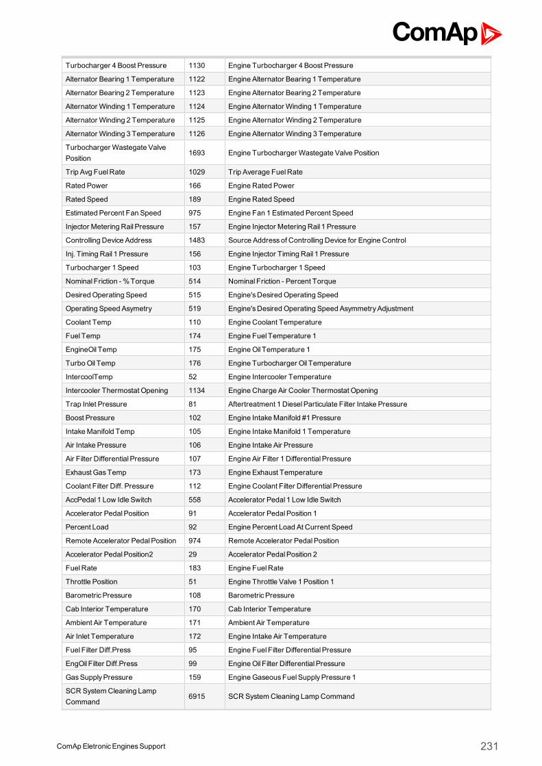
ComApEletronicEnginesSupport 231
Turbocharger 4 Boost Pressure 1130 Engine Turbocharger 4 Boost Pressure
Alternator Bearing 1 Temperature 1122 Engine Alternator Bearing 1 Temperature
Alternator Bearing 2 Temperature 1123 Engine Alternator Bearing 2 Temperature
Alternator Winding 1 Temperature 1124 Engine Alternator Winding 1 Temperature
Alternator Winding 2 Temperature 1125 Engine Alternator Winding 2 Temperature
Alternator Winding 3 Temperature 1126 Engine Alternator Winding 3 Temperature
Turbocharger Wastegate ValvePosition
1693 Engine Turbocharger Wastegate Valve Position
Trip Avg FuelRate 1029 Trip Average FuelRate
Rated Power 166 Engine Rated Power
Rated Speed 189 Engine Rated Speed
Estimated Percent Fan Speed 975 Engine Fan 1 Estimated Percent Speed
Injector Metering Rail Pressure 157 Engine Injector Metering Rail 1 Pressure
Controlling Device Address 1483 Source Addressof Controlling Device for Engine Control
Inj. Timing Rail 1 Pressure 156 Engine Injector Timing Rail 1 Pressure
Turbocharger 1 Speed 103 Engine Turbocharger 1 Speed
Nominal Friction - %Torque 514 Nominal Friction - Percent Torque
Desired Operating Speed 515 Engine'sDesired Operating Speed
Operating Speed Asymetry 519 Engine'sDesired Operating Speed AsymmetryAdjustment
Coolant Temp 110 Engine Coolant Temperature
Fuel Temp 174 Engine Fuel Temperature 1
EngineOil Temp 175 EngineOil Temperature 1
TurboOil Temp 176 Engine Turbocharger Oil Temperature
IntercoolTemp 52 Engine Intercooler Temperature
Intercooler Thermostat Opening 1134 Engine Charge Air Cooler Thermostat Opening
Trap Inlet Pressure 81 Aftertreatment 1 DieselParticulate Filter Intake Pressure
Boost Pressure 102 Engine IntakeManifold #1 Pressure
IntakeManifold Temp 105 Engine IntakeManifold 1 Temperature
Air Intake Pressure 106 Engine Intake Air Pressure
Air Filter Differential Pressure 107 Engine Air Filter 1 Differential Pressure
Exhaust GasTemp 173 Engine Exhaust Temperature
Coolant Filter Diff. Pressure 112 Engine Coolant Filter Differential Pressure
AccPedal 1 Low Idle Switch 558 Accelerator Pedal 1 Low Idle Switch
Accelerator PedalPosition 91 Accelerator PedalPosition 1
Percent Load 92 Engine Percent Load At Current Speed
Remote Accelerator PedalPosition 974 Remote Accelerator PedalPosition
Accelerator PedalPosition2 29 Accelerator PedalPosition 2
FuelRate 183 Engine FuelRate
Throttle Position 51 Engine Throttle Valve 1 Position 1
BarometricPressure 108 BarometricPressure
Cab Interior Temperature 170 Cab Interior Temperature
Ambient Air Temperature 171 Ambient Air Temperature
Air Inlet Temperature 172 Engine Intake Air Temperature
Fuel Filter Diff.Press 95 Engine Fuel Filter Differential Pressure
EngOil Filter Diff.Press 99 EngineOil Filter Differential Pressure
GasSupplyPressure 159 EngineGaseousFuelSupplyPressure 1
SCR SystemCleaning LampCommand
6915 SCR SystemCleaning LampCommand
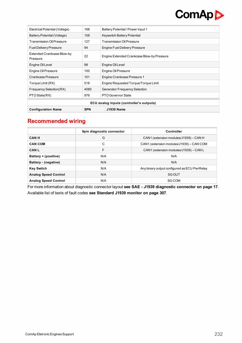
ComApEletronicEnginesSupport 232
ElectricalPotential (Voltage) 168 BatteryPotential / Power Input 1
BatteryPotential (Voltage) 158 Keyswitch BatteryPotential
TransmissionOil Pressure 127 TransmissionOil Pressure
FuelDeliveryPressure 94 Engine FuelDeliveryPressure
Extended Crankcase Blow-byPressure
22 Engine Extended Crankcase Blow-byPressure
EngineOil Level 98 EngineOil Level
EngineOil Pressure 100 EngineOil Pressure
Crankcase Pressure 101 Engine Crankcase Pressure 1
Torque Limit (RX) 518 Engine Requested Torque/Torque Limit
FrequencySelection(RX) 4080 Generator FrequencySelection
PTOState(RX) 976 PTOGovernor State
ECU analog inputs (controller's outputs)
Configuration Name SPN J1939 Name
Recommended wiring9pin diagnostic connector Controller
CAN H G CAN1 (extensionmodules/J1939) – CAN H
CAN COM C CAN1 (extensionmodules/J1939) – CAN COM
CAN L F CAN1 (extensionmodules/J1939) – CAN L
Battery + (positive) N/A N/A
Battery - (negative) N/A N/A
Key Switch N/A Anybinary output configured asECU PwrRelay
Analog Speed Control N/A SGOUT
Analog Speed Control N/A SGCOM
Formore information about diagnostic connector layout see SAE - J1939 diagnostic connector on page 17.Available list of texts of fault codes see Standard J1939 monitor on page 307.
ComApEletronicEnginesSupport 233
4 List of texts of ECU fault codes
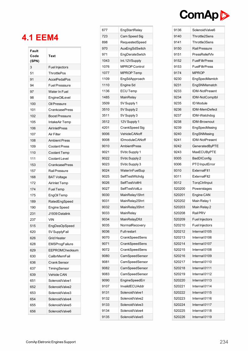
4.1 EEM4FaultCode(SPN)
Text
3 Fuel Injectors
51 ThrottlePos
91 AccelPedalPos
94 FuelPresssure
97 Water In Fuel
98 EngineOilLevel
100 Oil Pressure
101 CrankcasePress
102 Boost Pressure
105 IntakeAir Temp
106 AirInletPress
107 Air Filter
108 Ambient Press
109 Coolant Press
110 Coolant Temp
111 Coolant Level
153 CrankcasePress
157 Rail Pressure
168 BAT Voltage
172 AirInlet Temp
174 Fuel Temp
175 EngOil Temp
189 RatedEngSpeed
190 Engine Speed
231 J1939 Datalink
237 VIN
515 EngDesOpSpeed
620 5VSupplyFail
626 Grid Heater
628 EMSProgFailure
629 EEPROMChecksum
630 CalibrMemFail
636 CrankSensor
637 TimingSensor
639 Vehicle CAN
651 SolenoidValve1
652 SolenoidValve2
653 SolenoidValve3
654 SolenoidValve4
655 SolenoidValve5
656 SolenoidValve6
677 EngStartRelay
723 CamSpeed Sig
898 RequestedSpeed
970 AuxEngSdSwitch
971 EngDerateSwtch
1043 Int.12VSupply
1076 MPROPControl
1077 MPROPTemp
1109 EngSdApproach
1110 Engine Sd
1136 ECU Temp
1485 MainRelay
3509 5VSupply 1
3510 5VSupply 2
3511 5VSupply 3
3512 12VSupply 1
4201 CrankSpeed Sig
9006 VehicleCANoff
9008 IDmoduleCANoff
9010 AmbientPress
9021 5VdcSupply 1
9022 5VdcSupply 2
9023 5VdcSupply 3
9024 WaterInFuelSup
9025 SelfTestWtchdg
9026 SelfTestVoltHi
9027 SelfTestVoltLo
9030 MainRelay1Shrt
9031 MainRelay2Shrt
9032 MainRelay3Shrt
9033 MainRelay
9034 MainRelayDfct
9035 NormalRecovery
9036 Full restart
9070 CrankSpeedSens
9071 CrankSpeedSens
9072 CrankSpeedSens
9080 CamSpeedSensor
9081 CamSpeedSensor
9082 CamSpeedSensor
9083 CamSpeedSensor
9090 EngineSpeedErr
9107 InvalidECUAddr
9131 SolenoidValve1
9132 SolenoidValve2
9133 SolenoidValve3
9134 SolenoidValve4
9135 SolenoidValve5
9136 SolenoidValve6
9140 Throttle2Sens
9141 Throttle3Sens
9150 Rail Pressure
9151 PressReliefVlv
9152 FuelFiltrPress
9153 FuelFiltrPress
9174 MPROP
9230 EngSpecMismtch
9231 EngSNMismatch
9233 IDM-NotPresent
9234 IDM-NotComptbl
9235 ID Module
9236 IDM-MemDefect
9237 IDM-Watchdog
9238 IDM-Brownout
9239 EngSpecMissing
9240 EngSNMissing
9241 IDM-NotPresent
9242 GeneratedByPTE
9243 MaxECUByPTE
9305 BadDIConfig
9306 PTO InputError
9310 ExternalFlt1
9311 ExternalFlt2
9312 TorqCtrlInput
520200 Powerstages
520201 Engine CAN
520202 Main Relay1
520203 Main Relay2
520208 Rail PRV
520209 Fuel Injectors
520210 Fuel Injectors
520212 Internal 0105
520213 Internal 0106
520214 Internal 0107
520215 Internal 0108
520216 Internal 0109
520217 Internal 0110
520218 Internal 0111
520219 Internal 0112
520220 Internal 0113
520221 Internal 0114
520222 Internal 0115
520223 Internal 0116
520224 Internal 0117
520225 Internal 0118
520226 Internal 0119
ComApEletronicEnginesSupport 234
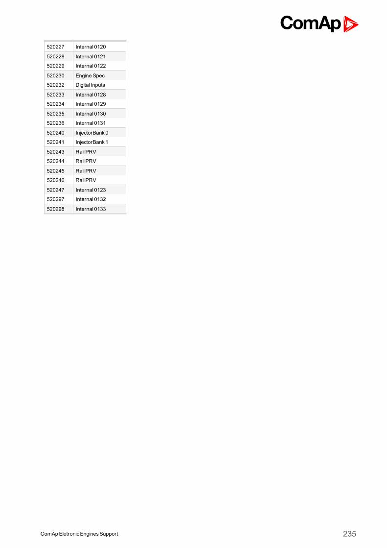
520227 Internal 0120
520228 Internal 0121
520229 Internal 0122
520230 Engine Spec
520232 Digital Inputs
520233 Internal 0128
520234 Internal 0129
520235 Internal 0130
520236 Internal 0131
520240 InjectorBank0
520241 InjectorBank1
520243 Rail PRV
520244 Rail PRV
520245 Rail PRV
520246 Rail PRV
520247 Internal 0123
520297 Internal 0132
520298 Internal 0133
ComApEletronicEnginesSupport 235
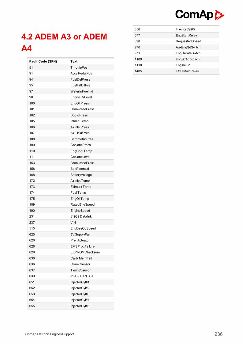
4.2 ADEM A3 or ADEMA4
Fault Code (SPN) Text
51 ThrottlePos
91 AccelPedalPos
94 FuelDelPress
95 FuelFiltDifPre
97 WaterInFuelInd
98 EngineOilLevel
100 EngOil Press
101 CrankcasePress
102 Boost Press
105 Intake Temp
106 AirInletPress
107 AirFiltDifPres
108 BarometricPres
109 Coolant Press
110 EngCool Temp
111 Coolant Level
153 CrankcasePress
158 BattPotential
168 BatteryVoltage
172 AirInlet Temp
173 Exhaust Temp
174 Fuel Temp
175 EngOil Temp
189 RatedEngSpeed
190 EngineSpeed
231 J1939 Datalink
237 VIN
515 EngDesOpSpeed
620 5VSupplyFail
626 PrehActuator
628 EMSProgFailure
629 EEPROMChecksum
630 CalibrMemFail
636 CrankSensor
637 TimingSensor
639 J1939 CAN Bus
651 InjectorCyl#1
652 InjectorCyl#2
653 InjectorCyl#3
654 InjectorCyl#4
655 InjectorCyl#5
656 InjectorCyl#6
677 EngStartRelay
898 RequestedSpeed
970 AuxEngSdSwitch
971 EngDerateSwtch
1109 EngSdApproach
1110 Engine Sd
1485 ECUMainRelay
ComApEletronicEnginesSupport 236
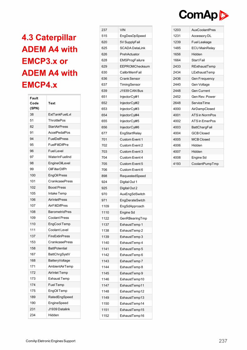
4.3 CaterpillarADEM A4 withEMCP3.x orADEM A4 withEMCP4.x
FaultCode(SPN)
Text
38 ExtTankFuelLvl
51 ThrottlePos
82 StartAirPress
91 AccelPedalPos
94 FuelDelPress
95 FuelFiltDifPre
96 Fuel Level
97 WaterInFuelInd
98 EngineOilLevel
99 OilFilterDifPr
100 EngOil Press
101 CrankcasePress
102 Boost Press
105 Intake Temp
106 AirInletPress
107 AirFiltDifPres
108 BarometricPres
109 Coolant Press
110 EngCool Temp
111 Coolant Level
137 FireExtinPress
153 CrankcasePress
158 BattPotential
167 BattChrgSystV
168 BatteryVoltage
171 AmbientAirTemp
172 AirInlet Temp
173 Exhaust Temp
174 Fuel Temp
175 EngOil Temp
189 RatedEngSpeed
190 EngineSpeed
231 J1939 Datalink
234 Hidden
237 VIN
515 EngDesOpSpeed
620 5VSupplyFail
625 SCADADataLink
626 PrehActuator
628 EMSProgFailure
629 EEPROMChecksum
630 CalibrMemFail
636 CrankSensor
637 TimingSensor
639 J1939 CAN Bus
651 InjectorCyl#1
652 InjectorCyl#2
653 InjectorCyl#3
654 InjectorCyl#4
655 InjectorCyl#5
656 InjectorCyl#6
677 EngStartRelay
701 CustomEvent 1
702 CustomEvent 2
703 CustomEvent 3
704 CustomEvent 4
705 CustomEvent 5
706 CustomEvent 6
898 RequestedSpeed
924 DigitalOut 1
925 DigitalOut 2
970 AuxEngSdSwitch
971 EngDerateSwtch
1109 EngSdApproach
1110 Engine Sd
1122 GenRBearingTmp
1137 ExhaustTemp 1
1138 ExhaustTemp 2
1139 ExhaustTemp 3
1140 ExhaustTemp 4
1141 ExhaustTemp 5
1142 ExhaustTemp 6
1143 ExhaustTemp 7
1144 ExhaustTemp 8
1145 ExhaustTemp 9
1146 ExhaustTemp10
1147 ExhaustTemp11
1148 ExhaustTemp12
1149 ExhaustTemp13
1150 ExhaustTemp14
1151 ExhaustTemp15
1152 ExhaustTemp16
1203 AuxCoolantPres
1231 AccessoryDL
1239 Fuel Leakage
1485 ECUMainRelay
1656 Hidden
1664 Start Fail
2433 RExthaustTemp
2434 LExthaustTemp
2436 Gen Frequency
2440 Gen Voltage
2448 GenCurrent
2452 GenRev. Power
2648 ServiceTime
4000 AirDampClosed
4001 ATS in NormPos
4002 ATS in EmerPos
4003 BattChargFail
4004 GCBClosed
4005 MCBClosed
4006 Hidden
4007 Hidden
4008 Engine Sd
4193 CoolantPumpTmp
ComApEletronicEnginesSupport 237
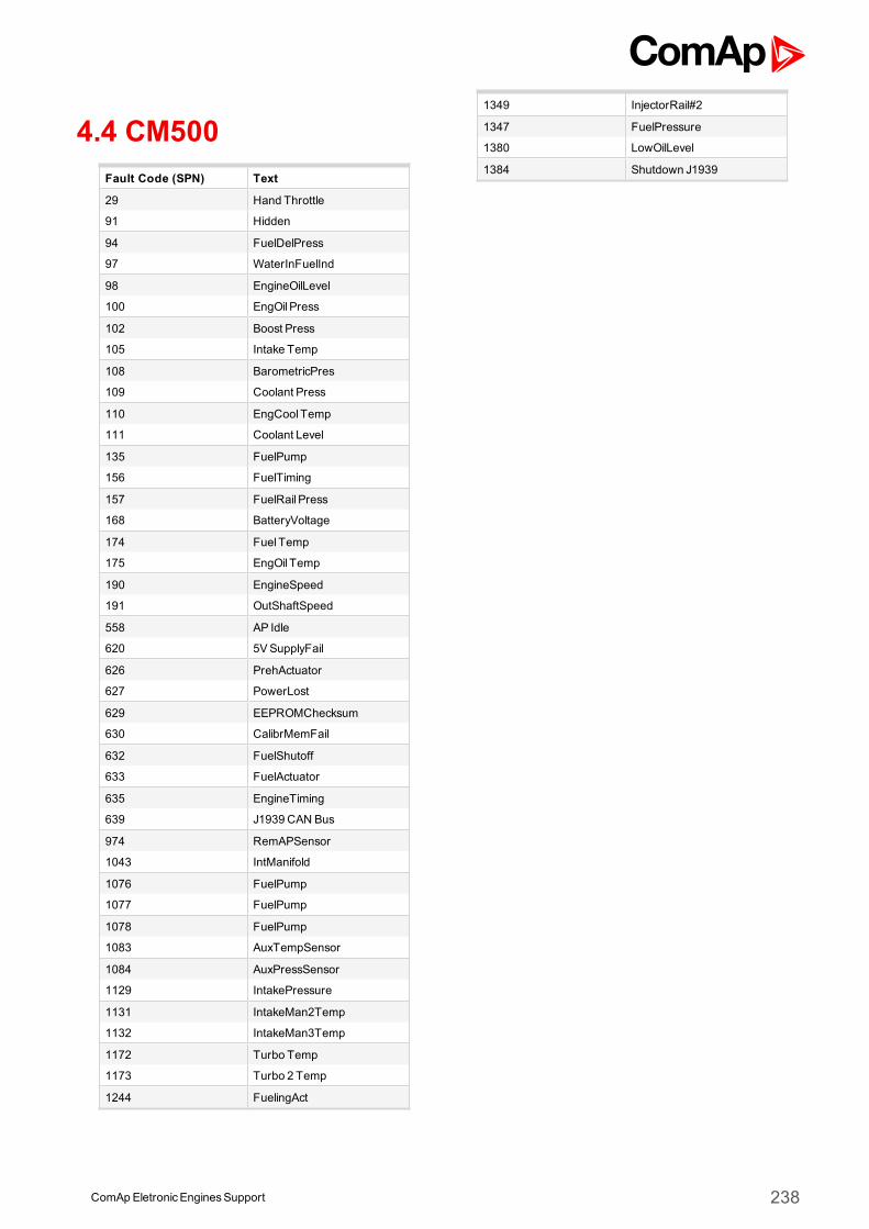
4.4 CM500Fault Code (SPN) Text
29 Hand Throttle
91 Hidden
94 FuelDelPress
97 WaterInFuelInd
98 EngineOilLevel
100 EngOil Press
102 Boost Press
105 Intake Temp
108 BarometricPres
109 Coolant Press
110 EngCool Temp
111 Coolant Level
135 FuelPump
156 FuelTiming
157 FuelRail Press
168 BatteryVoltage
174 Fuel Temp
175 EngOil Temp
190 EngineSpeed
191 OutShaftSpeed
558 AP Idle
620 5VSupplyFail
626 PrehActuator
627 PowerLost
629 EEPROMChecksum
630 CalibrMemFail
632 FuelShutoff
633 FuelActuator
635 EngineTiming
639 J1939 CAN Bus
974 RemAPSensor
1043 IntManifold
1076 FuelPump
1077 FuelPump
1078 FuelPump
1083 AuxTempSensor
1084 AuxPressSensor
1129 IntakePressure
1131 IntakeMan2Temp
1132 IntakeMan3Temp
1172 Turbo Temp
1173 Turbo 2 Temp
1244 FuelingAct
1349 InjectorRail#2
1347 FuelPressure
1380 LowOilLevel
1384 Shutdown J1939
ComApEletronicEnginesSupport 238
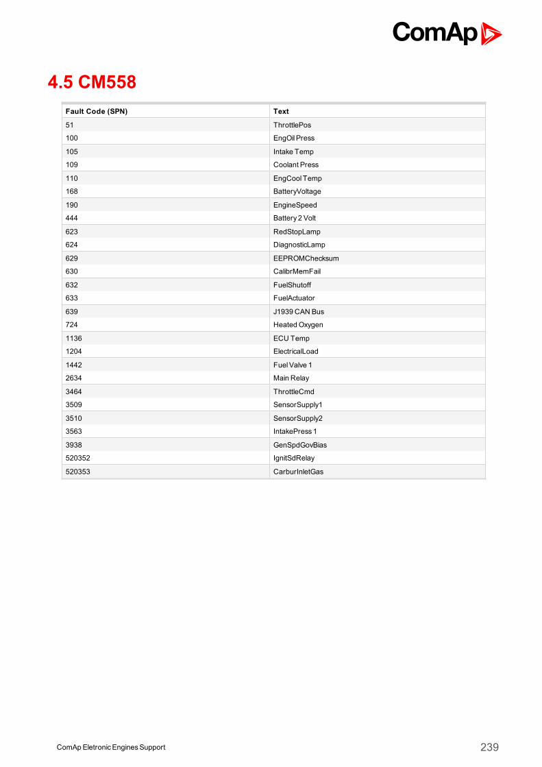
ComApEletronicEnginesSupport 239
4.5 CM558Fault Code (SPN) Text
51 ThrottlePos
100 EngOil Press
105 Intake Temp
109 Coolant Press
110 EngCool Temp
168 BatteryVoltage
190 EngineSpeed
444 Battery 2 Volt
623 RedStopLamp
624 DiagnosticLamp
629 EEPROMChecksum
630 CalibrMemFail
632 FuelShutoff
633 FuelActuator
639 J1939 CAN Bus
724 HeatedOxygen
1136 ECU Temp
1204 ElectricalLoad
1442 FuelValve 1
2634 Main Relay
3464 ThrottleCmd
3509 SensorSupply1
3510 SensorSupply2
3563 IntakePress1
3938 GenSpdGovBias
520352 IgnitSdRelay
520353 CarburInletGas
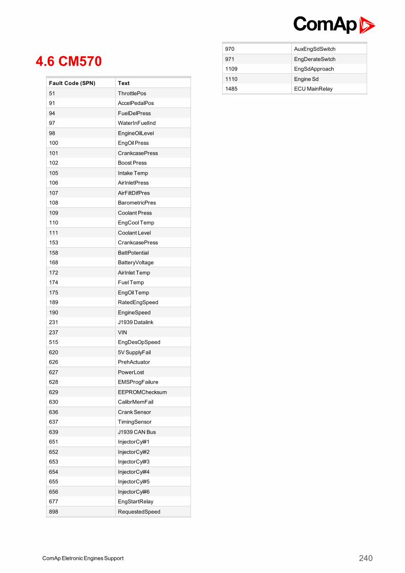
4.6 CM570Fault Code (SPN) Text
51 ThrottlePos
91 AccelPedalPos
94 FuelDelPress
97 WaterInFuelInd
98 EngineOilLevel
100 EngOil Press
101 CrankcasePress
102 Boost Press
105 Intake Temp
106 AirInletPress
107 AirFiltDifPres
108 BarometricPres
109 Coolant Press
110 EngCool Temp
111 Coolant Level
153 CrankcasePress
158 BattPotential
168 BatteryVoltage
172 AirInlet Temp
174 Fuel Temp
175 EngOil Temp
189 RatedEngSpeed
190 EngineSpeed
231 J1939 Datalink
237 VIN
515 EngDesOpSpeed
620 5VSupplyFail
626 PrehActuator
627 PowerLost
628 EMSProgFailure
629 EEPROMChecksum
630 CalibrMemFail
636 CrankSensor
637 TimingSensor
639 J1939 CAN Bus
651 InjectorCyl#1
652 InjectorCyl#2
653 InjectorCyl#3
654 InjectorCyl#4
655 InjectorCyl#5
656 InjectorCyl#6
677 EngStartRelay
898 RequestedSpeed
970 AuxEngSdSwitch
971 EngDerateSwtch
1109 EngSdApproach
1110 Engine Sd
1485 ECUMainRelay
ComApEletronicEnginesSupport 240

4.7 CM800Fault Code (SPN) Text
51 ThrottlePos
91 AccelPedalPos
94 FuelDelPress
97 WaterInFuelInd
98 EngineOilLevel
100 EngOil Press
101 CrankcasePress
102 Boost Press
105 Intake Temp
106 AirInletPress
107 AirFiltDifPres
108 BarometricPres
109 Coolant Press
110 EngCool Temp
111 Coolant Level
153 CrankcasePress
158 BattPotential
168 BatteryVoltage
172 AirInlet Temp
174 Fuel Temp
175 EngOil Temp
189 RatedEngSpeed
190 EngineSpeed
231 J1939 Datalink
237 VIN
515 EngDesOpSpeed
620 5VSupplyFail
626 PrehActuator
627 PowerLost
628 EMSProgFailure
629 EEPROMChecksum
630 CalibrMemFail
636 CrankSensor
637 TimingSensor
639 J1939 CAN Bus
651 InjectorCyl#1
652 InjectorCyl#2
653 InjectorCyl#3
654 InjectorCyl#4
655 InjectorCyl#5
656 InjectorCyl#6
677 EngStartRelay
898 RequestedSpeed
970 AuxEngSdSwitch
971 EngDerateSwtch
1109 EngSdApproach
1110 Engine Sd
1485 ECUMainRelay
ComApEletronicEnginesSupport 241
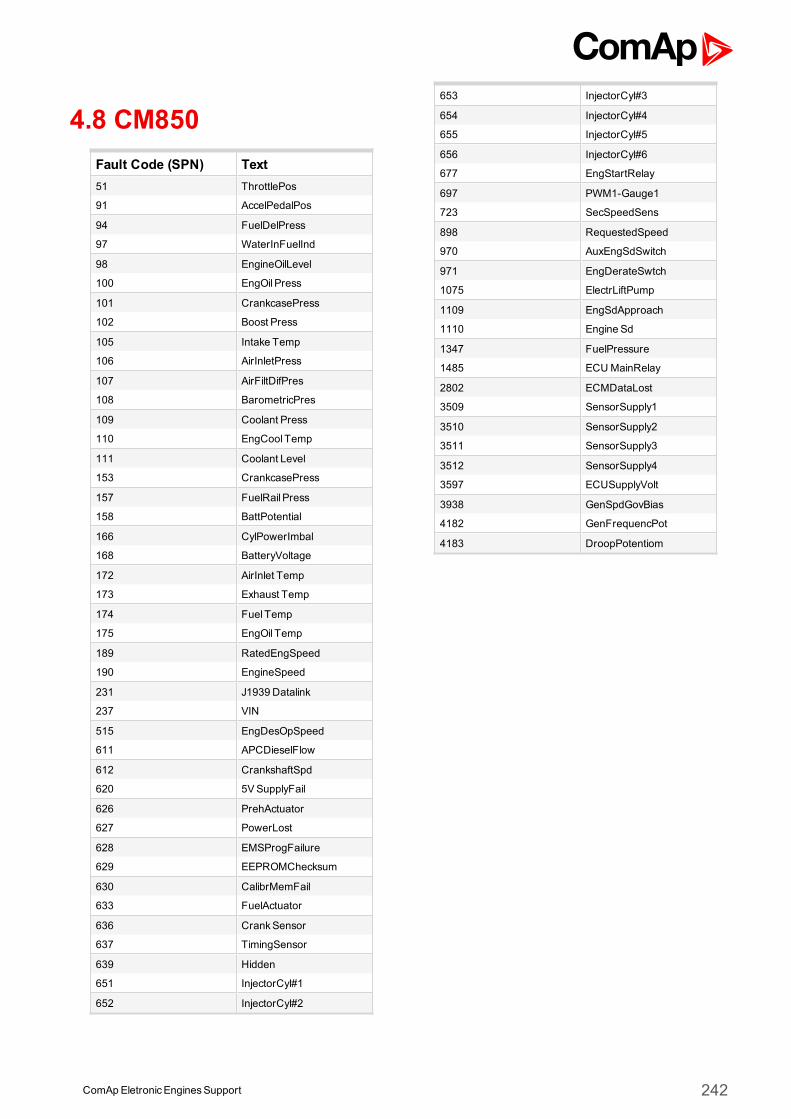
4.8 CM850Fault Code (SPN) Text51 ThrottlePos
91 AccelPedalPos
94 FuelDelPress
97 WaterInFuelInd
98 EngineOilLevel
100 EngOil Press
101 CrankcasePress
102 Boost Press
105 Intake Temp
106 AirInletPress
107 AirFiltDifPres
108 BarometricPres
109 Coolant Press
110 EngCool Temp
111 Coolant Level
153 CrankcasePress
157 FuelRail Press
158 BattPotential
166 CylPowerImbal
168 BatteryVoltage
172 AirInlet Temp
173 Exhaust Temp
174 Fuel Temp
175 EngOil Temp
189 RatedEngSpeed
190 EngineSpeed
231 J1939 Datalink
237 VIN
515 EngDesOpSpeed
611 APCDieselFlow
612 CrankshaftSpd
620 5VSupplyFail
626 PrehActuator
627 PowerLost
628 EMSProgFailure
629 EEPROMChecksum
630 CalibrMemFail
633 FuelActuator
636 CrankSensor
637 TimingSensor
639 Hidden
651 InjectorCyl#1
652 InjectorCyl#2
653 InjectorCyl#3
654 InjectorCyl#4
655 InjectorCyl#5
656 InjectorCyl#6
677 EngStartRelay
697 PWM1-Gauge1
723 SecSpeedSens
898 RequestedSpeed
970 AuxEngSdSwitch
971 EngDerateSwtch
1075 ElectrLiftPump
1109 EngSdApproach
1110 Engine Sd
1347 FuelPressure
1485 ECUMainRelay
2802 ECMDataLost
3509 SensorSupply1
3510 SensorSupply2
3511 SensorSupply3
3512 SensorSupply4
3597 ECUSupplyVolt
3938 GenSpdGovBias
4182 GenFrequencPot
4183 DroopPotentiom
ComApEletronicEnginesSupport 242
ComApEletronicEnginesSupport 243
4.9 CM2150
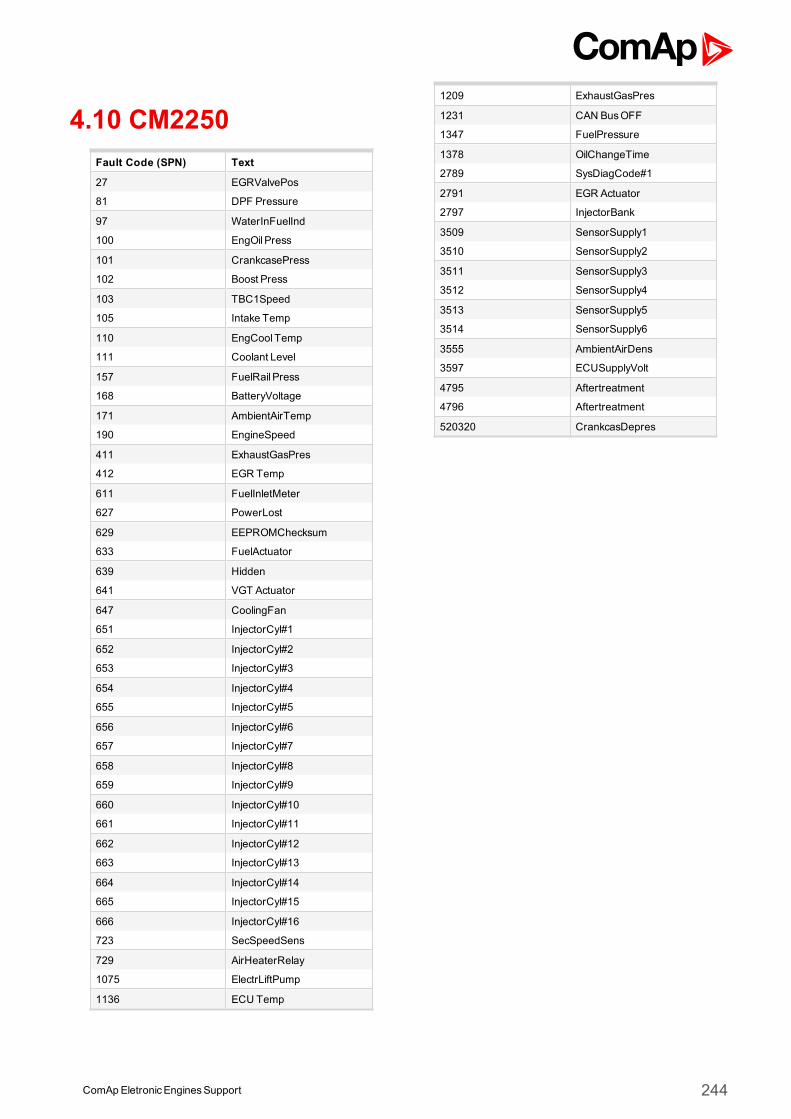
4.10 CM2250Fault Code (SPN) Text
27 EGRValvePos
81 DPF Pressure
97 WaterInFuelInd
100 EngOil Press
101 CrankcasePress
102 Boost Press
103 TBC1Speed
105 Intake Temp
110 EngCool Temp
111 Coolant Level
157 FuelRail Press
168 BatteryVoltage
171 AmbientAirTemp
190 EngineSpeed
411 ExhaustGasPres
412 EGR Temp
611 FuelInletMeter
627 PowerLost
629 EEPROMChecksum
633 FuelActuator
639 Hidden
641 VGT Actuator
647 CoolingFan
651 InjectorCyl#1
652 InjectorCyl#2
653 InjectorCyl#3
654 InjectorCyl#4
655 InjectorCyl#5
656 InjectorCyl#6
657 InjectorCyl#7
658 InjectorCyl#8
659 InjectorCyl#9
660 InjectorCyl#10
661 InjectorCyl#11
662 InjectorCyl#12
663 InjectorCyl#13
664 InjectorCyl#14
665 InjectorCyl#15
666 InjectorCyl#16
723 SecSpeedSens
729 AirHeaterRelay
1075 ElectrLiftPump
1136 ECU Temp
1209 ExhaustGasPres
1231 CAN BusOFF
1347 FuelPressure
1378 OilChangeTime
2789 SysDiagCode#1
2791 EGR Actuator
2797 InjectorBank
3509 SensorSupply1
3510 SensorSupply2
3511 SensorSupply3
3512 SensorSupply4
3513 SensorSupply5
3514 SensorSupply6
3555 AmbientAirDens
3597 ECUSupplyVolt
4795 Aftertreatment
4796 Aftertreatment
520320 CrankcasDepres
ComApEletronicEnginesSupport 244
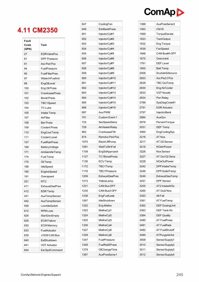
4.11 CM2350FaultCode(SPN)
Text
27 EGRValvePos
81 DPF Pressure
91 AccPed Pos
94 FuelPressure
95 FuelFilterPres
97 WaterInFuelInd
98 EngOilLevel
100 EngOil Press
101 CrankcasePress
102 Boost Press
103 TBC1Speed
104 TC Lube
105 Intake Temp
107 AirFilter
108 Bar Press
109 Coolant Press
110 EngCool Temp
111 Coolant Level
157 FuelRail Press
168 BatteryVoltage
171 AmbientAirTemp
174 Fuel Temp
175 Oil Temp
188 IdleSpeed
190 EngineSpeed
191 Overspeed
251 RTC
411 ExhaustGasPres
412 EGR Temp
441 AuxTempSensor
442 AuxTempSensor
558 LowIdleSwitch
612 RPM Loss
626 StartDevEmpty
629 ECMFailure
630 ECMMemory
633 FuelActuator
639 J1939 CAN Bus
640 ExtShutdown
641 VGT Actuator
644 Ext SpdCommand
647 CoolingFan
649 ExhBackPress
651 InjectorCyl#1
652 InjectorCyl#2
653 InjectorCyl#3
654 InjectorCyl#4
655 InjectorCyl#5
656 InjectorCyl#6
657 InjectorCyl#7
658 InjectorCyl#8
659 InjectorCyl#9
660 InjectorCyl#10
661 InjectorCyl#11
662 InjectorCyl#12
663 InjectorCyl#13
664 InjectorCyl#14
665 InjectorCyl#15
666 InjectorCyl#16
697 AuxPWM
701 CustomEvent 1
723 SecSpeedSens
729 AirHeaterRelay
862 CrankcaseFiltr
974 RemAccPed Pos
1075 ElectrLiftPump
1081 WaitToStrtFail
1109 EngSdApproach
1127 TC1BoostPress
1136 ECU Temp
1172 TBC1Temp
1176 TBC1Pressure
1209 ExhaustGasPres
1213 YellowLamp
1231 CAN BusOFF
1235 CAN Bus3OFF
1239 EngFuelLeak
1267 IdleShutdown
1322 EngMisfire
1323 MisfireCyl1
1324 MisfireCyl2
1325 MisfireCyl3
1326 MisfireCyl4
1327 MisfireCyl5
1328 MisfireCyl6
1347 FuelPressure
1349 FuelRail2Press
1378 OilChangeTime
1387 AuxPresSensr1
1388 AuxPresSensr2
1563 CM ID
1569 TorqueDerate
1623 TachOutput
1632 Eng Torque
1639 FanSpeed
1668 CAN Bus#4OFF
1675 Overcrank
1761 DEF Level
1800 Batt Temp
2006 SrcAddr6Abnorm
2623 AccPed 2 Pos
2629 TBCOutTemp
2630 Eng AirCooler
2633 VGT Nozzle
2634 Pwr Relay
2789 SysDiagCode#1
2791 EGR Actuator
2797 InjectorBank
2884 AuxGov
2978 PercentTorque
3031 DEF Temp
3060 EngCoolingSys
3216 AT Nox
3217 AT O2Sensor
3218 NOxInPower
3226 NoxSensor
3227 AT Out O2 Sens
3228 NOxOutPower
3242 DPFIntakeTemp
3246 DPFOutletTemp
3249 ExhaustGasTemp
3251 DPF Sensor
3255 AT2 IntakeNOx
3265 AT Out2 Nox
3353 Alt Fail
3361 AT FuelTemp
3362 DEF DosingUnit
3363 DEF TankHtr
3364 DEF Quality
3480 AT FuelPress
3481 AT FuelRate
3482 AT FuelShutoff
3490 ATPurgeAirAct
3509 SensorSupply1
3510 SensorSupply2
3511 SensorSupply3
3512 SensorSupply4
ComApEletronicEnginesSupport 245
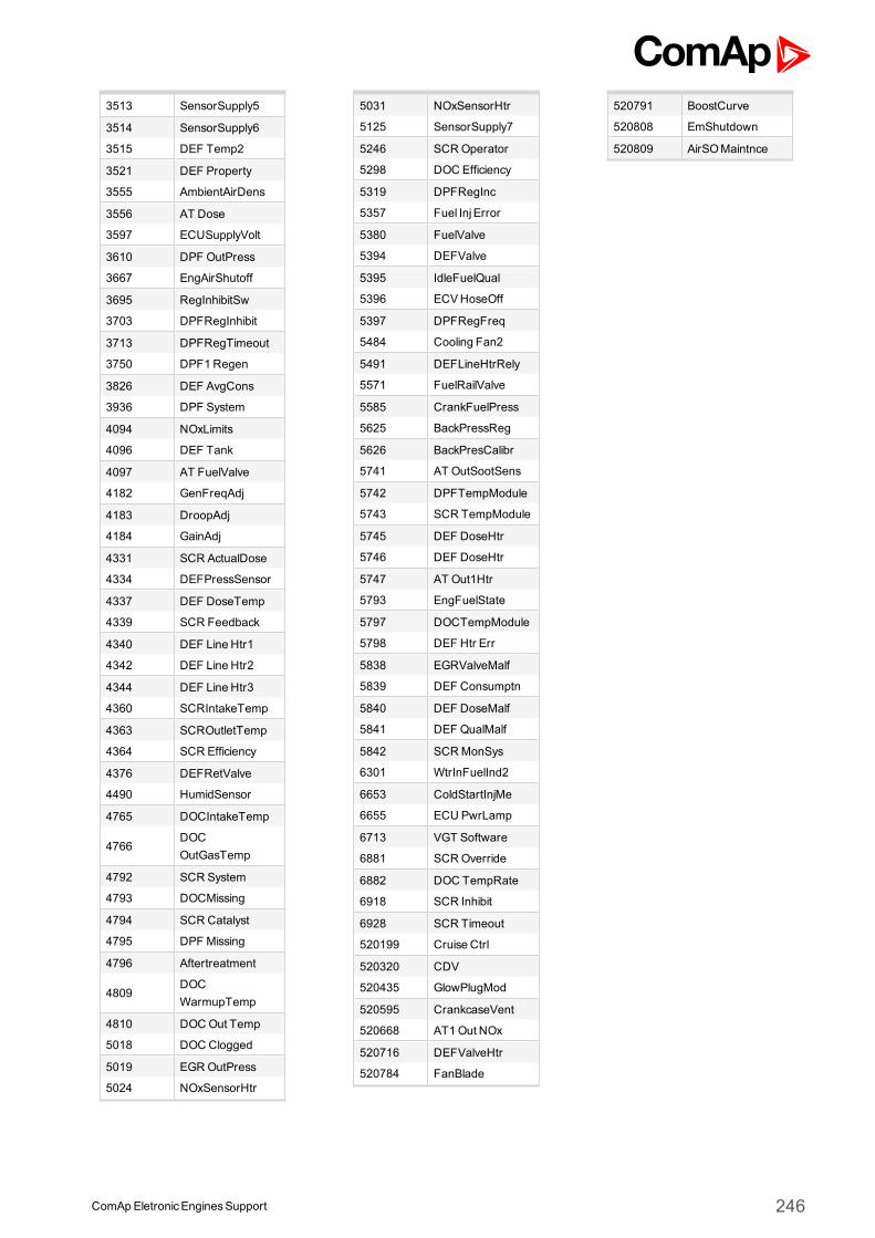
3513 SensorSupply5
3514 SensorSupply6
3515 DEF Temp2
3521 DEF Property
3555 AmbientAirDens
3556 AT Dose
3597 ECUSupplyVolt
3610 DPF OutPress
3667 EngAirShutoff
3695 RegInhibitSw
3703 DPFRegInhibit
3713 DPFRegTimeout
3750 DPF1Regen
3826 DEF AvgCons
3936 DPF System
4094 NOxLimits
4096 DEF Tank
4097 AT FuelValve
4182 GenFreqAdj
4183 DroopAdj
4184 GainAdj
4331 SCR ActualDose
4334 DEFPressSensor
4337 DEF DoseTemp
4339 SCR Feedback
4340 DEF Line Htr1
4342 DEF Line Htr2
4344 DEF Line Htr3
4360 SCRIntakeTemp
4363 SCROutletTemp
4364 SCR Efficiency
4376 DEFRetValve
4490 HumidSensor
4765 DOCIntakeTemp
4766DOCOutGasTemp
4792 SCR System
4793 DOCMissing
4794 SCR Catalyst
4795 DPF Missing
4796 Aftertreatment
4809DOCWarmupTemp
4810 DOCOut Temp
5018 DOCClogged
5019 EGROutPress
5024 NOxSensorHtr
5031 NOxSensorHtr
5125 SensorSupply7
5246 SCROperator
5298 DOC Efficiency
5319 DPFRegInc
5357 Fuel Inj Error
5380 FuelValve
5394 DEFValve
5395 IdleFuelQual
5396 ECVHoseOff
5397 DPFRegFreq
5484 Cooling Fan2
5491 DEFLineHtrRely
5571 FuelRailValve
5585 CrankFuelPress
5625 BackPressReg
5626 BackPresCalibr
5741 AT OutSootSens
5742 DPFTempModule
5743 SCR TempModule
5745 DEF DoseHtr
5746 DEF DoseHtr
5747 AT Out1Htr
5793 EngFuelState
5797 DOCTempModule
5798 DEF Htr Err
5838 EGRValveMalf
5839 DEF Consumptn
5840 DEF DoseMalf
5841 DEF QualMalf
5842 SCRMonSys
6301 WtrInFuelInd2
6653 ColdStartInjMe
6655 ECU PwrLamp
6713 VGT Software
6881 SCROverride
6882 DOC TempRate
6918 SCR Inhibit
6928 SCR Timeout
520199 Cruise Ctrl
520320 CDV
520435 GlowPlugMod
520595 CrankcaseVent
520668 AT1Out NOx
520716 DEFValveHtr
520784 FanBlade
520791 BoostCurve
520808 EmShutdown
520809 AirSOMaintnce
ComApEletronicEnginesSupport 246
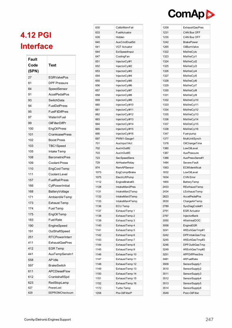
4.12 PGIInterface
FaultCode(SPN)
Text
27 EGRValvePos
81 DPF Pressure
84 SpeedSensor
91 AccelPedalPos
93 SwitchData
94 FuelDelPress
95 FuelFilDifPres
97 WaterInFuel
99 OilFilterDifPr
100 EngOil Press
101 CrankcasePress
102 Boost Press
103 TBC1Speed
105 Intake Temp
108 BarometricPres
109 Coolant Press
110 EngCool Temp
111 Coolant Level
157 FuelRail Press
166 CylPowerImbal
168 BatteryVoltage
171 AmbientAirTemp
173 Exhaust Temp
174 Fuel Temp
175 EngOil Temp
183 FuelRate
190 EngineSpeed
191 OutShaftSpeed
251 RTCPowerInterr
411 ExhaustGasPres
412 EGR Temp
441 AuxTempSensIn1
558 AP Idle
597 BrakeSwitch
611 APCDieselFlow
612 CrankshaftSpd
623 RedStopLamp627 PowerLost
629 EEPROMChecksum
630 CalibrMemFail
633 FuelActuator
639 Hidden
640 AuxCmdDualSd
641 VGT Actuator
644 ExtSpeedInput
647 CoolingFan
651 InjectorCyl#1
652 InjectorCyl#2
653 InjectorCyl#3
654 InjectorCyl#4
655 InjectorCyl#5
656 InjectorCyl#6
657 InjectorCyl#7
658 InjectorCyl#8
659 InjectorCyl#9
660 InjectorCyl#10
661 InjectorCyl#11
662 InjectorCyl#12
663 InjectorCyl#13
664 InjectorCyl#14
665 InjectorCyl#15
666 InjectorCyl#16
697 PWM1-Gauge1
701 AuxInput1Act
702 AuxInOut#2
703 AuxInOut#3
723 SecSpeedSens
729 AirHeaterRelay
974 RemAPSensor
1073 EngComprBrake
1075 ElectrLiftPump
1112 EngineBrake#3
1128 IntakeMan2Pres
1131 IntakeMan2Temp
1132 IntakeMan3Temp
1133 IntakeMan4Temp
1136 ECU Temp
1137 ExhaustTemp 1
1138 ExhaustTemp 2
1139 ExhaustTemp 3
1140 ExhaustTemp 4
1141 ExhaustTemp 5
1142 ExhaustTemp 6
1143 ExhaustTemp 7
1144 ExhaustTemp 8
1145 ExhaustTemp 9
1146 ExhaustTemp 10
1147 ExhaustTemp 11
1148 ExhaustTemp 12
1149 ExhaustTemp 13
1150 ExhaustTemp 14
1151 ExhaustTemp 15
1152 ExhaustTemp 16
1172 Turbo Temp
1208 Pre-OilFilterP
1209 ExhaustGasPres
1231 CAN Bus OFF
1235 CAN Bus OFF
1242 BrakePower
1265 OilBurnValve
1322 MisfireCyls
1323 MisfireCyl1
1324 MisfireCyl2
1325 MisfireCyl3
1326 MisfireCyl4
1327 MisfireCyl5
1328 MisfireCyl6
1329 MisfireCyl7
1330 MisfireCyl8
1331 MisfireCyl9
1332 MisfireCyl10
1333 MisfireCyl11
1334 MisfireCyl12
1335 MisfireCyl13
1336 MisfireCyl14
1337 MisfireCyl15
1338 MisfireCyl16
1347 Fuel-pump
1377 MultUnitSynch
1378 OilChangeTime
1380 LowOilLevel
1387 AuxPressure
1388 AuxPressSens#1
1484 Severe Fault
1563 ECMIdentificat
1632 LowOilLevel
1634 CVN Error
1800 BatteryTemp
2433 RExthaustTemp
2434 LExthaustTemp
2623 AccelPedalPos
2630 ChargeAirTemp
2789 SysDiagCode#1
2791 EGR Actuator
2797 InjectorBank
3050 AftertreatDOC
3058 EngineEGR
3241 AftExhGasTmp#1
3242 DPFIntakGasTmp
3245 AftExhGasTmp#3
3246 DPFOutltGasTmp
3249 AftExhGasTmp#2
3251 APFDiffPresSns
3481 AftFuelRate
3509 SensorSupply1
3510 SensorSupply2
3511 SensorSupply3
3512 SensorSupply4
3513 SensorSupply5
3514 SensorSupply6
3549 Post-OilFilter
ComApEletronicEnginesSupport 247
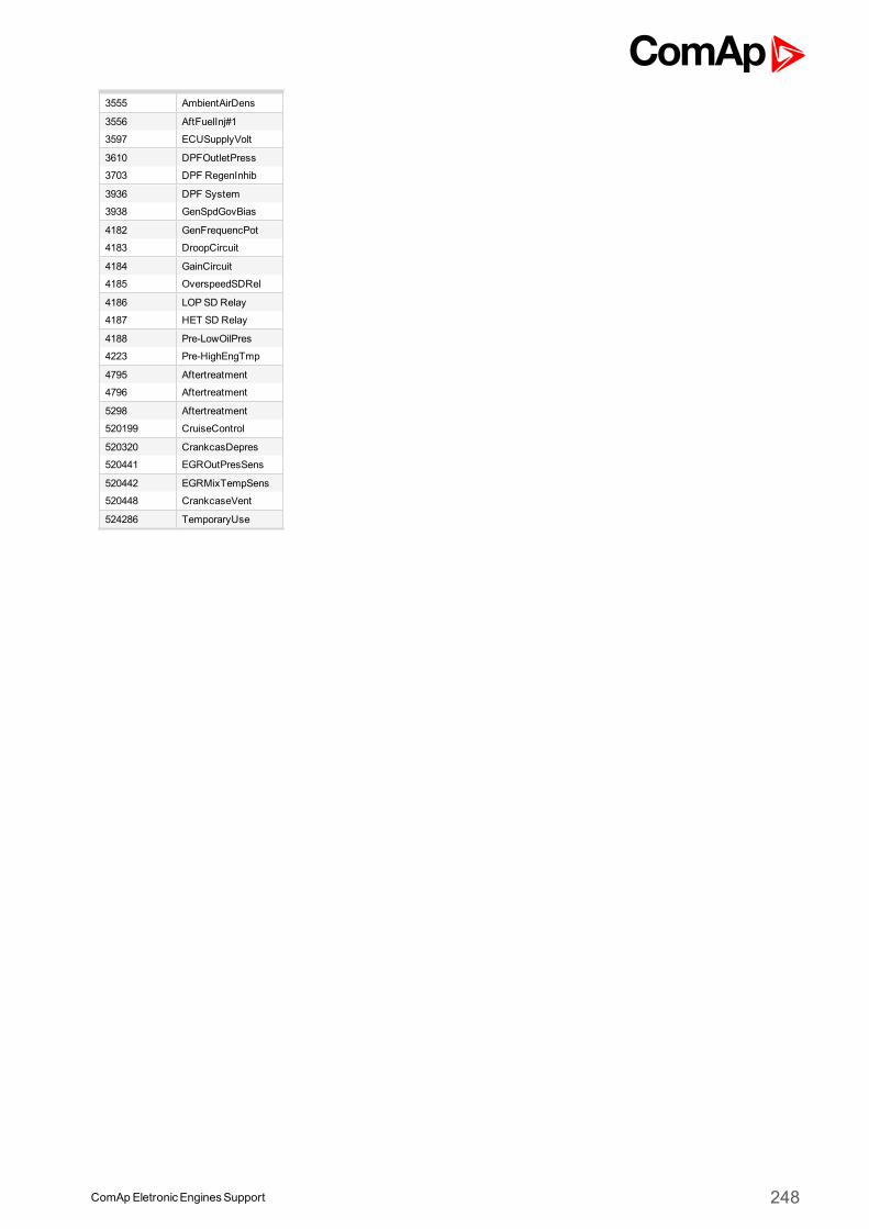
3555 AmbientAirDens
3556 AftFuelInj#1
3597 ECUSupplyVolt
3610 DPFOutletPress
3703 DPF RegenInhib
3936 DPF System
3938 GenSpdGovBias
4182 GenFrequencPot
4183 DroopCircuit
4184 GainCircuit
4185 OverspeedSDRel
4186 LOPSD Relay
4187 HET SD Relay
4188 Pre-LowOilPres
4223 Pre-HighEngTmp
4795 Aftertreatment
4796 Aftertreatment
5298 Aftertreatment
520199 CruiseControl
520320 CrankcasDepres
520441 EGROutPresSens
520442 EGRMixTempSens
520448 CrankcaseVent
524286 TemporaryUse
ComApEletronicEnginesSupport 248
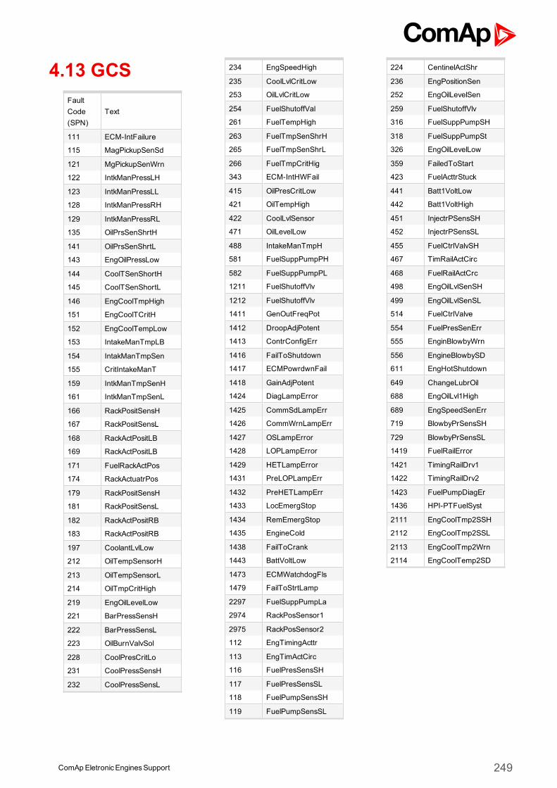
4.13 GCSFaultCode(SPN)
Text
111 ECM-IntFailure
115 MagPickupSenSd
121 MgPickupSenWrn
122 IntkManPressLH
123 IntkManPressLL
128 IntkManPressRH
129 IntkManPressRL
135 OilPrsSenShrtH
141 OilPrsSenShrtL
143 EngOilPressLow
144 CoolTSenShortH
145 CoolTSenShortL
146 EngCoolTmpHigh
151 EngCoolTCritH
152 EngCoolTempLow
153 IntakeManTmpLB
154 IntakManTmpSen
155 CritIntakeManT
159 IntkManTmpSenH
161 IntkManTmpSenL
166 RackPositSensH
167 RackPositSensL
168 RackActPositLB
169 RackActPositLB
171 FuelRackActPos
174 RackActuatrPos
179 RackPositSensH
181 RackPositSensL
182 RackActPositRB
183 RackActPositRB
197 CoolantLvlLow
212 OilTempSensorH
213 OilTempSensorL
214 OilTmpCritHigh
219 EngOilLevelLow
221 BarPressSensH
222 BarPressSensL
223 OilBurnValvSol
228 CoolPresCritLo
231 CoolPressSensH
232 CoolPressSensL
234 EngSpeedHigh
235 CoolLvlCritLow
253 OilLvlCritLow
254 FuelShutoffVal
261 FuelTempHigh
263 FuelTmpSenShrH
265 FuelTmpSenShrL
266 FuelTmpCritHig
343 ECM-IntHWFail
415 OilPresCritLow
421 OilTempHigh
422 CoolLvlSensor
471 OilLevelLow
488 IntakeManTmpH
581 FuelSuppPumpPH
582 FuelSuppPumpPL
1211 FuelShutoffVlv
1212 FuelShutoffVlv
1411 GenOutFreqPot
1412 DroopAdjPotent
1413 ContrConfigErr
1416 FailToShutdown
1417 ECMPowrdwnFail
1418 GainAdjPotent
1424 DiagLampError
1425 CommSdLampErr
1426 CommWrnLampErr
1427 OSLampError
1428 LOPLampError
1429 HETLampError
1431 PreLOPLampErr
1432 PreHETLampErr
1433 LocEmergStop
1434 RemEmergStop
1435 EngineCold
1438 FailToCrank
1443 BattVoltLow
1473 ECMWatchdogFls
1479 FailToStrtLamp
2297 FuelSuppPumpLa
2974 RackPosSensor1
2975 RackPosSensor2
112 EngTimingActtr
113 EngTimActCirc
116 FuelPresSensSH
117 FuelPresSensSL
118 FuelPumpSensSH
119 FuelPumpSensSL
224 CentinelActShr
236 EngPositionSen
252 EngOilLevelSen
259 FuelShutoffVlv
316 FuelSuppPumpSH
318 FuelSuppPumpSt
326 EngOilLevelLow
359 FailedToStart
423 FuelActtrStuck
441 Batt1VoltLow
442 Batt1VoltHigh
451 InjectrPSensSH
452 InjectrPSensSL
455 FuelCtrlValvSH
467 TimRailActCirc
468 FuelRailActCrc
498 EngOilLvlSenSH
499 EngOilLvlSenSL
514 FuelCtrlValve
554 FuelPresSenErr
555 EnginBlowbyWrn
556 EngineBlowbySD
611 EngHotShutdown
649 ChangeLubrOil
688 EngOilLvl1High
689 EngSpeedSenErr
719 BlowbyPrSensSH
729 BlowbyPrSensSL
1419 FuelRailError
1421 TimingRailDrv1
1422 TimingRailDrv2
1423 FuelPumpDiagEr
1436 HPI-PTFuelSyst
2111 EngCoolTmp2SSH
2112 EngCoolTmp2SSL
2113 EngCoolTmp2Wrn
2114 EngCoolTemp2SD
ComApEletronicEnginesSupport 249
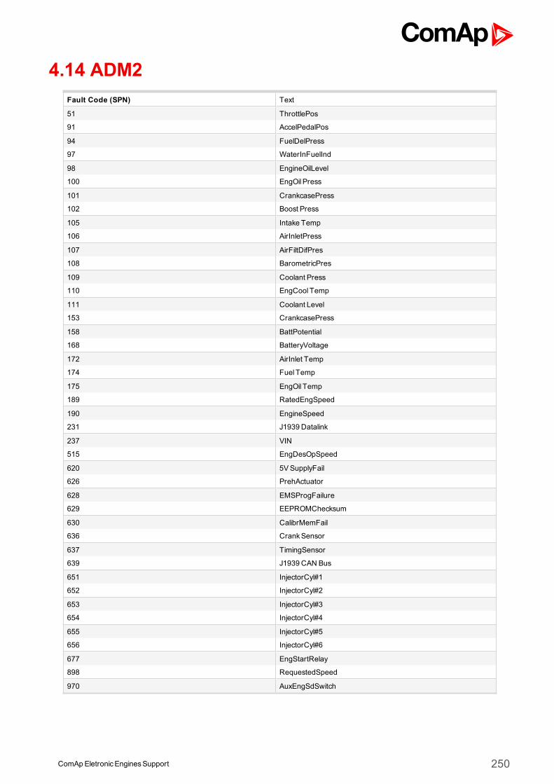
ComApEletronicEnginesSupport 250
4.14 ADM2Fault Code (SPN) Text
51 ThrottlePos
91 AccelPedalPos
94 FuelDelPress
97 WaterInFuelInd
98 EngineOilLevel
100 EngOil Press
101 CrankcasePress
102 Boost Press
105 Intake Temp
106 AirInletPress
107 AirFiltDifPres
108 BarometricPres
109 Coolant Press
110 EngCool Temp
111 Coolant Level
153 CrankcasePress
158 BattPotential
168 BatteryVoltage
172 AirInlet Temp
174 Fuel Temp
175 EngOil Temp
189 RatedEngSpeed
190 EngineSpeed
231 J1939 Datalink
237 VIN
515 EngDesOpSpeed
620 5VSupplyFail
626 PrehActuator
628 EMSProgFailure
629 EEPROMChecksum
630 CalibrMemFail
636 CrankSensor
637 TimingSensor
639 J1939 CAN Bus
651 InjectorCyl#1
652 InjectorCyl#2
653 InjectorCyl#3
654 InjectorCyl#4
655 InjectorCyl#5
656 InjectorCyl#6
677 EngStartRelay
898 RequestedSpeed
970 AuxEngSdSwitch
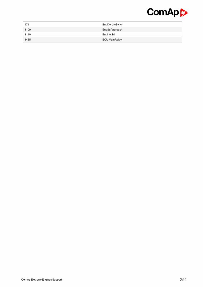
ComApEletronicEnginesSupport 251
971 EngDerateSwtch
1109 EngSdApproach
1110 Engine Sd
1485 ECUMainRelay

4.15 ADM3Fault Code (SPN) Text51 ThrottlePos
91 AccelPedalPos
94 FuelDelPress
97 WaterInFuelInd
98 EngineOilLevel
100 EngOil Press
101 CrankcasePress
102 Boost Press
105 Intake Temp
106 AirInletPress
107 AirFiltDifPres
108 BarometricPres
109 Coolant Press
110 EngCool Temp
111 Coolant Level
153 CrankcasePress
158 BattPotential
168 BatteryVoltage
172 AirInlet Temp
174 Fuel Temp
175 EngOil Temp
189 RatedEngSpeed
190 EngineSpeed
231 J1939 Datalink
237 VIN
515 EngDesOpSpeed
620 5VSupplyFail
626 PrehActuator
628 EMSProgFailure
629 EEPROMChecksum
630 CalibrMemFail
636 CrankSensor
637 TimingSensor
639 J1939 CAN Bus
651 InjectorCyl#1
652 InjectorCyl#2
653 InjectorCyl#3
654 InjectorCyl#4
655 InjectorCyl#5
656 InjectorCyl#6
677 EngStartRelay
898 RequestedSpeed
970 AuxEngSdSwitch
971 EngDerateSwtch
1109 EngSdApproach
1110 Engine Sd
1485 ECUMainRelay
ComApEletronicEnginesSupport 252

4.16 DDEC IVFault Code (SPN) Text51 ThrottlePos
91 AccelPedalPos
94 FuelDelPress
97 WaterInFuelInd
98 EngineOilLevel
100 EngOil Press
101 CrankcasePress
102 Boost Press
105 Intake Temp
106 AirInletPress
107 AirFiltDifPres
108 BarometricPres
109 Coolant Press
110 EngCool Temp
111 Coolant Level
153 CrankcasePress
158 BattPotential
168 BatteryVoltage
172 AirInlet Temp
173 Exhaust Temp
174 Fuel Temp
175 EngOil Temp
189 RatedEngSpeed
190 EngineSpeed
231 J1939 Datalink
237 VIN
515 EngDesOpSpeed
620 5VSupplyFail
626 PrehActuator
628 EMSProgFailure
629 EEPROMChecksum
630 CalibrMemFail
636 CrankSensor
637 TimingSensor
639 J1939 CAN Bus
651 InjectorCyl#1
652 InjectorCyl#2
653 InjectorCyl#3
654 InjectorCyl#4
655 InjectorCyl#5
656 InjectorCyl#6
677 EngStartRelay
898 RequestedSpeed
970 AuxEngSdSwitch
971 EngDerateSwtch
1109 EngSdApproach
1110 Engine Sd
1485 ECUMainRelay
ComApEletronicEnginesSupport 253
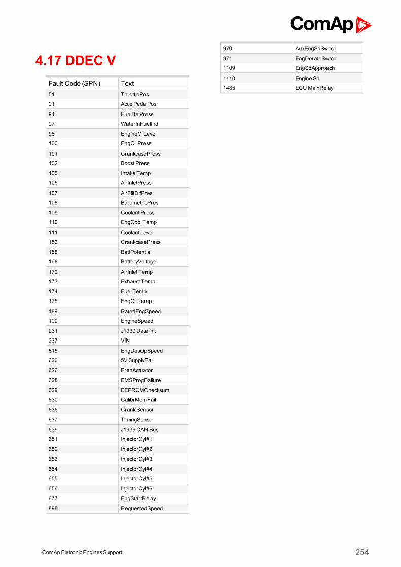
4.17 DDEC VFault Code (SPN) Text51 ThrottlePos
91 AccelPedalPos
94 FuelDelPress
97 WaterInFuelInd
98 EngineOilLevel
100 EngOil Press
101 CrankcasePress
102 Boost Press
105 Intake Temp
106 AirInletPress
107 AirFiltDifPres
108 BarometricPres
109 Coolant Press
110 EngCool Temp
111 Coolant Level
153 CrankcasePress
158 BattPotential
168 BatteryVoltage
172 AirInlet Temp
173 Exhaust Temp
174 Fuel Temp
175 EngOil Temp
189 RatedEngSpeed
190 EngineSpeed
231 J1939 Datalink
237 VIN
515 EngDesOpSpeed
620 5VSupplyFail
626 PrehActuator
628 EMSProgFailure
629 EEPROMChecksum
630 CalibrMemFail
636 CrankSensor
637 TimingSensor
639 J1939 CAN Bus
651 InjectorCyl#1
652 InjectorCyl#2
653 InjectorCyl#3
654 InjectorCyl#4
655 InjectorCyl#5
656 InjectorCyl#6
677 EngStartRelay
898 RequestedSpeed
970 AuxEngSdSwitch
971 EngDerateSwtch
1109 EngSdApproach
1110 Engine Sd
1485 ECUMainRelay
ComApEletronicEnginesSupport 254
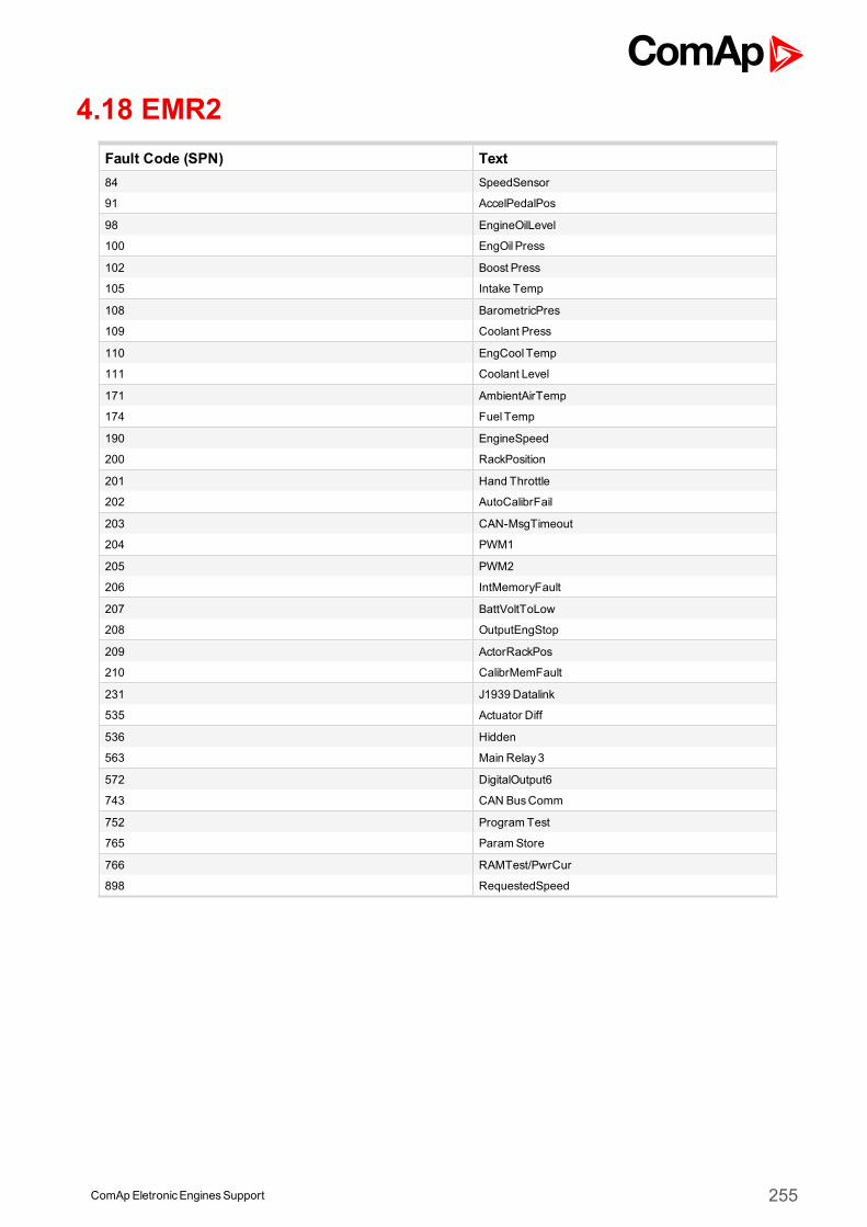
ComApEletronicEnginesSupport 255
4.18 EMR2Fault Code (SPN) Text84 SpeedSensor
91 AccelPedalPos
98 EngineOilLevel
100 EngOil Press
102 Boost Press
105 Intake Temp
108 BarometricPres
109 Coolant Press
110 EngCool Temp
111 Coolant Level
171 AmbientAirTemp
174 Fuel Temp
190 EngineSpeed
200 RackPosition
201 Hand Throttle
202 AutoCalibrFail
203 CAN-MsgTimeout
204 PWM1
205 PWM2
206 IntMemoryFault
207 BattVoltToLow
208 OutputEngStop
209 ActorRackPos
210 CalibrMemFault
231 J1939 Datalink
535 Actuator Diff
536 Hidden
563 Main Relay3
572 DigitalOutput6
743 CAN BusComm
752 Program Test
765 ParamStore
766 RAMTest/PwrCur
898 RequestedSpeed
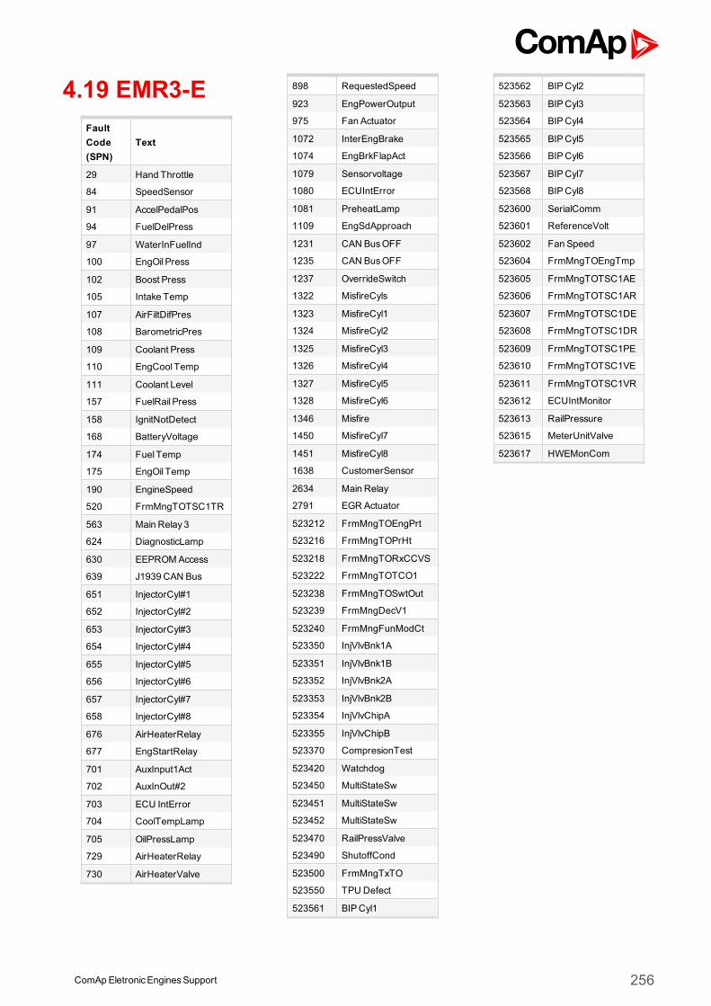
4.19 EMR3-EFaultCode(SPN)
Text
29 Hand Throttle
84 SpeedSensor
91 AccelPedalPos
94 FuelDelPress
97 WaterInFuelInd
100 EngOil Press
102 Boost Press
105 Intake Temp
107 AirFiltDifPres
108 BarometricPres
109 Coolant Press
110 EngCool Temp
111 Coolant Level
157 FuelRail Press
158 IgnitNotDetect
168 BatteryVoltage
174 Fuel Temp
175 EngOil Temp
190 EngineSpeed
520 FrmMngTOTSC1TR
563 Main Relay3
624 DiagnosticLamp
630 EEPROMAccess
639 J1939 CAN Bus
651 InjectorCyl#1
652 InjectorCyl#2
653 InjectorCyl#3
654 InjectorCyl#4
655 InjectorCyl#5
656 InjectorCyl#6
657 InjectorCyl#7
658 InjectorCyl#8
676 AirHeaterRelay
677 EngStartRelay
701 AuxInput1Act
702 AuxInOut#2
703 ECU IntError
704 CoolTempLamp
705 OilPressLamp
729 AirHeaterRelay
730 AirHeaterValve
898 RequestedSpeed
923 EngPowerOutput
975 Fan Actuator
1072 InterEngBrake
1074 EngBrkFlapAct
1079 Sensorvoltage
1080 ECUIntError
1081 PreheatLamp
1109 EngSdApproach
1231 CAN BusOFF
1235 CAN BusOFF
1237 OverrideSwitch
1322 MisfireCyls
1323 MisfireCyl1
1324 MisfireCyl2
1325 MisfireCyl3
1326 MisfireCyl4
1327 MisfireCyl5
1328 MisfireCyl6
1346 Misfire
1450 MisfireCyl7
1451 MisfireCyl8
1638 CustomerSensor
2634 Main Relay
2791 EGR Actuator
523212 FrmMngTOEngPrt
523216 FrmMngTOPrHt
523218 FrmMngTORxCCVS
523222 FrmMngTOTCO1
523238 FrmMngTOSwtOut
523239 FrmMngDecV1
523240 FrmMngFunModCt
523350 InjVlvBnk1A
523351 InjVlvBnk1B
523352 InjVlvBnk2A
523353 InjVlvBnk2B
523354 InjVlvChipA
523355 InjVlvChipB
523370 CompresionTest
523420 Watchdog
523450 MultiStateSw
523451 MultiStateSw
523452 MultiStateSw
523470 RailPressValve
523490 ShutoffCond
523500 FrmMngTxTO
523550 TPU Defect
523561 BIPCyl1
523562 BIPCyl2
523563 BIPCyl3
523564 BIPCyl4
523565 BIPCyl5
523566 BIPCyl6
523567 BIPCyl7
523568 BIPCyl8
523600 SerialComm
523601 ReferenceVolt
523602 Fan Speed
523604 FrmMngTOEngTmp
523605 FrmMngTOTSC1AE
523606 FrmMngTOTSC1AR
523607 FrmMngTOTSC1DE
523608 FrmMngTOTSC1DR
523609 FrmMngTOTSC1PE
523610 FrmMngTOTSC1VE
523611 FrmMngTOTSC1VR
523612 ECUIntMonitor
523613 RailPressure
523615 MeterUnitValve
523617 HWEMonCom
ComApEletronicEnginesSupport 256

4.20 EMR3-SFaultCode(SPN)
Text
29 Hand Throttle
84 SpeedSensor
91 AccelPedalPos
94 FuelDelPress
97 WaterInFuelInd
100 EngOil Press
102 Boost Press
105 Intake Temp
107 AirFiltDifPres
108 BarometricPres
109 Coolant Press
110 EngCool Temp
111 Coolant Level
157 FuelRail Press
158 IgnitNotDetect
168 BatteryVoltage
174 Fuel Temp
175 EngOil Temp
190 EngineSpeed
520 FrmMngTOTSC1TR
563 Main Relay3
624 DiagnosticLamp
630 EEPROMAccess
639 J1939 CAN Bus
651 InjectorCyl#1
652 InjectorCyl#2
653 InjectorCyl#3
654 InjectorCyl#4
655 InjectorCyl#5
656 InjectorCyl#6
657 InjectorCyl#7
658 InjectorCyl#8
676 AirHeaterRelay
677 EngStartRelay
701 AuxInput1Act
702 AuxInOut#2
703 ECU IntError
704 CoolTempLamp
705 OilPressLamp
729 AirHeaterRelay
730 AirHeaterValve
898 RequestedSpeed
923 EngPowerOutput
975 Fan Actuator
1072 InterEngBrake
1074 EngBrkFlapAct
1079 Sensorvoltage
1080 ECUIntError
1081 PreheatLamp
1109 EngSdApproach
1231 CAN BusOFF
1235 CAN BusOFF
1237 OverrideSwitch
1322 MisfireCyls
1323 MisfireCyl1
1324 MisfireCyl2
1325 MisfireCyl3
1326 MisfireCyl4
1327 MisfireCyl5
1328 MisfireCyl6
1346 Misfire
1450 MisfireCyl7
1451 MisfireCyl8
1638 CustomerSensor
2634 Main Relay
2791 EGR Actuator
523212 FrmMngTOEngPrt
523216 FrmMngTOPrHt
523218 FrmMngTORxCCVS
523222 FrmMngTOTCO1
523238 FrmMngTOSwtOut
523239 FrmMngDecV1
523240 FrmMngFunModCt
523350 InjVlvBnk1A
523351 InjVlvBnk1B
523352 InjVlvBnk2A
523353 InjVlvBnk2B
523354 InjVlvChipA
523355 InjVlvChipB
523370 CompresionTest
523420 Watchdog
523450 MultiStateSw
523451 MultiStateSw
523452 MultiStateSw
523470 RailPressValve
523490 ShutoffCond
523500 FrmMngTxTO
523550 TPU Defect
523561 BIPCyl1
523562 BIPCyl2
523563 BIPCyl3
523564 BIPCyl4
523565 BIPCyl5
523566 BIPCyl6
523567 BIPCyl7
523568 BIPCyl8
523600 SerialComm
523601 ReferenceVolt
523602 Fan Speed
523604 FrmMngTOEngTmp
523605 FrmMngTOTSC1AE
523606 FrmMngTOTSC1AR
523607 FrmMngTOTSC1DE
523608 FrmMngTOTSC1DR
523609 FrmMngTOTSC1PE
523610 FrmMngTOTSC1VE
523611 FrmMngTOTSC1VR
523612 ECUIntMonitor
523613 RailPressure
523615 MeterUnitValve
523617 HWEMonCom
ComApEletronicEnginesSupport 257
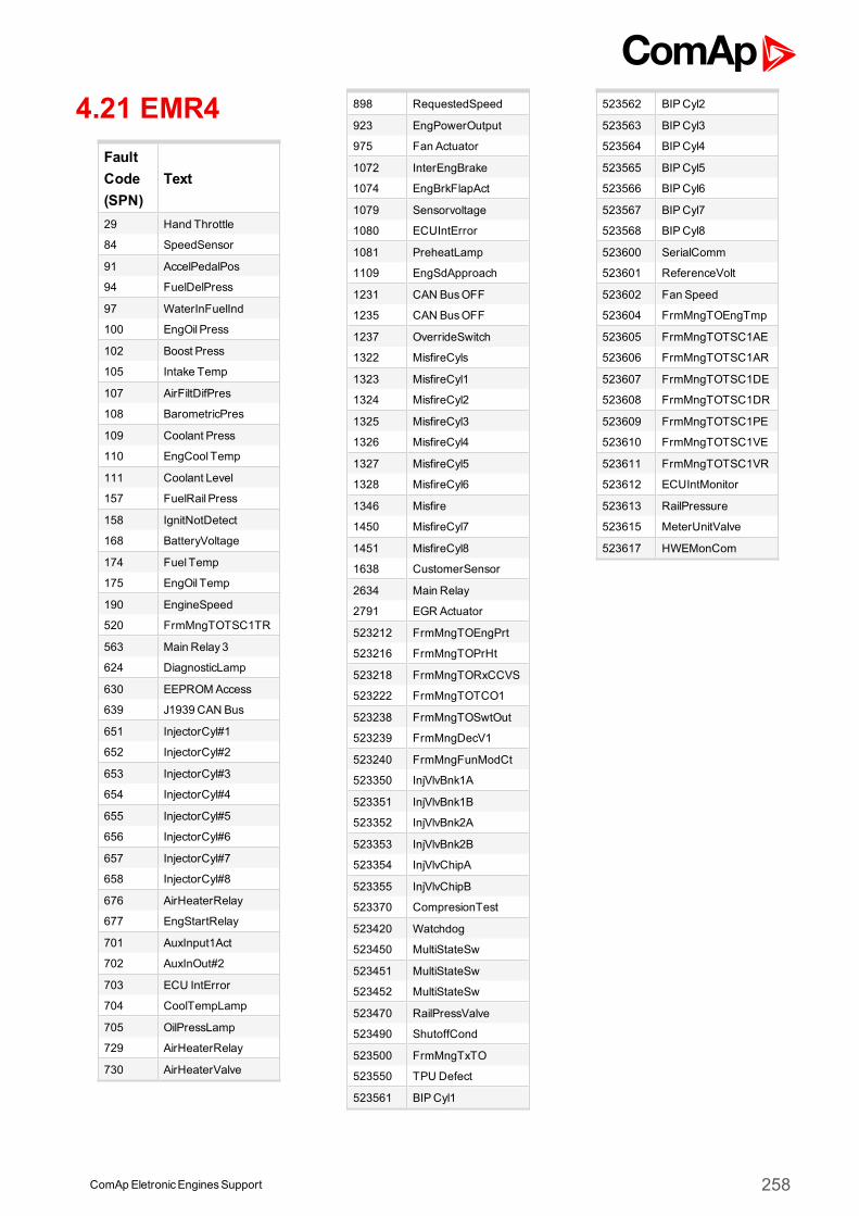
4.21 EMR4FaultCode(SPN)
Text
29 Hand Throttle
84 SpeedSensor
91 AccelPedalPos
94 FuelDelPress
97 WaterInFuelInd
100 EngOil Press
102 Boost Press
105 Intake Temp
107 AirFiltDifPres
108 BarometricPres
109 Coolant Press
110 EngCool Temp
111 Coolant Level
157 FuelRail Press
158 IgnitNotDetect
168 BatteryVoltage
174 Fuel Temp
175 EngOil Temp
190 EngineSpeed
520 FrmMngTOTSC1TR
563 Main Relay3
624 DiagnosticLamp
630 EEPROMAccess
639 J1939 CAN Bus
651 InjectorCyl#1
652 InjectorCyl#2
653 InjectorCyl#3
654 InjectorCyl#4
655 InjectorCyl#5
656 InjectorCyl#6
657 InjectorCyl#7
658 InjectorCyl#8
676 AirHeaterRelay
677 EngStartRelay
701 AuxInput1Act
702 AuxInOut#2
703 ECU IntError
704 CoolTempLamp
705 OilPressLamp
729 AirHeaterRelay
730 AirHeaterValve
898 RequestedSpeed
923 EngPowerOutput
975 Fan Actuator
1072 InterEngBrake
1074 EngBrkFlapAct
1079 Sensorvoltage
1080 ECUIntError
1081 PreheatLamp
1109 EngSdApproach
1231 CAN BusOFF
1235 CAN BusOFF
1237 OverrideSwitch
1322 MisfireCyls
1323 MisfireCyl1
1324 MisfireCyl2
1325 MisfireCyl3
1326 MisfireCyl4
1327 MisfireCyl5
1328 MisfireCyl6
1346 Misfire
1450 MisfireCyl7
1451 MisfireCyl8
1638 CustomerSensor
2634 Main Relay
2791 EGR Actuator
523212 FrmMngTOEngPrt
523216 FrmMngTOPrHt
523218 FrmMngTORxCCVS
523222 FrmMngTOTCO1
523238 FrmMngTOSwtOut
523239 FrmMngDecV1
523240 FrmMngFunModCt
523350 InjVlvBnk1A
523351 InjVlvBnk1B
523352 InjVlvBnk2A
523353 InjVlvBnk2B
523354 InjVlvChipA
523355 InjVlvChipB
523370 CompresionTest
523420 Watchdog
523450 MultiStateSw
523451 MultiStateSw
523452 MultiStateSw
523470 RailPressValve
523490 ShutoffCond
523500 FrmMngTxTO
523550 TPU Defect
523561 BIPCyl1
523562 BIPCyl2
523563 BIPCyl3
523564 BIPCyl4
523565 BIPCyl5
523566 BIPCyl6
523567 BIPCyl7
523568 BIPCyl8
523600 SerialComm
523601 ReferenceVolt
523602 Fan Speed
523604 FrmMngTOEngTmp
523605 FrmMngTOTSC1AE
523606 FrmMngTOTSC1AR
523607 FrmMngTOTSC1DE
523608 FrmMngTOTSC1DR
523609 FrmMngTOTSC1PE
523610 FrmMngTOTSC1VE
523611 FrmMngTOTSC1VR
523612 ECUIntMonitor
523613 RailPressure
523615 MeterUnitValve
523617 HWEMonCom
ComApEletronicEnginesSupport 258
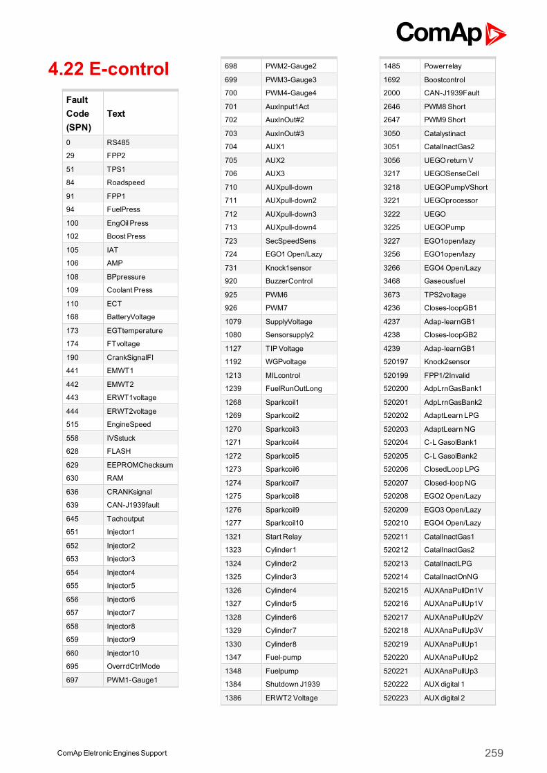
4.22 E-controlFaultCode(SPN)
Text
0 RS485
29 FPP2
51 TPS1
84 Roadspeed
91 FPP1
94 FuelPress
100 EngOil Press
102 Boost Press
105 IAT
106 AMP
108 BPpressure
109 Coolant Press
110 ECT
168 BatteryVoltage
173 EGTtemperature
174 FTvoltage
190 CrankSignalFl
441 EMWT1
442 EMWT2
443 ERWT1voltage
444 ERWT2voltage
515 EngineSpeed
558 IVSstuck
628 FLASH
629 EEPROMChecksum
630 RAM
636 CRANKsignal
639 CAN-J1939fault
645 Tachoutput
651 Injector1
652 Injector2
653 Injector3
654 Injector4
655 Injector5
656 Injector6
657 Injector7
658 Injector8
659 Injector9
660 Injector10
695 OverrdCtrlMode
697 PWM1-Gauge1
698 PWM2-Gauge2
699 PWM3-Gauge3
700 PWM4-Gauge4
701 AuxInput1Act
702 AuxInOut#2
703 AuxInOut#3
704 AUX1
705 AUX2
706 AUX3
710 AUXpull-down
711 AUXpull-down2
712 AUXpull-down3
713 AUXpull-down4
723 SecSpeedSens
724 EGO1Open/Lazy
731 Knock1sensor
920 BuzzerControl
925 PWM6
926 PWM7
1079 SupplyVoltage
1080 Sensorsupply2
1127 TIPVoltage
1192 WGPvoltage
1213 MILcontrol
1239 FuelRunOutLong
1268 Sparkcoil1
1269 Sparkcoil2
1270 Sparkcoil3
1271 Sparkcoil4
1272 Sparkcoil5
1273 Sparkcoil6
1274 Sparkcoil7
1275 Sparkcoil8
1276 Sparkcoil9
1277 Sparkcoil10
1321 Start Relay
1323 Cylinder1
1324 Cylinder2
1325 Cylinder3
1326 Cylinder4
1327 Cylinder5
1328 Cylinder6
1329 Cylinder7
1330 Cylinder8
1347 Fuel-pump
1348 Fuelpump
1384 Shutdown J1939
1386 ERWT2Voltage
1485 Powerrelay
1692 Boostcontrol
2000 CAN-J1939Fault
2646 PWM8Short
2647 PWM9Short
3050 Catalystinact
3051 CatalInactGas2
3056 UEGOreturn V
3217 UEGOSenseCell
3218 UEGOPumpVShort
3221 UEGOprocessor
3222 UEGO
3225 UEGOPump
3227 EGO1open/lazy
3256 EGO1open/lazy
3266 EGO4Open/Lazy
3468 Gaseousfuel
3673 TPS2voltage
4236 Closes-loopGB1
4237 Adap-learnGB1
4238 Closes-loopGB2
4239 Adap-learnGB1
520197 Knock2sensor
520199 FPP1/2Invalid
520200 AdpLrnGasBank1
520201 AdpLrnGasBank2
520202 AdaptLearn LPG
520203 AdaptLearn NG
520204 C-LGasolBank1
520205 C-LGasolBank2
520206 ClosedLoop LPG
520207 Closed-loop NG
520208 EGO2Open/Lazy
520209 EGO3Open/Lazy
520210 EGO4Open/Lazy
520211 CatalInactGas1
520212 CatalInactGas2
520213 CatalInactLPG
520214 CatalInactOnNG
520215 AUXAnaPullDn1V
520216 AUXAnaPullUp1V
520217 AUXAnaPullUp2V
520218 AUXAnaPullUp3V
520219 AUXAnaPullUp1
520220 AUXAnaPullUp2
520221 AUXAnaPullUp3
520222 AUXdigital 1
520223 AUXdigital 2
ComAp EletronicEnginesSupport 259
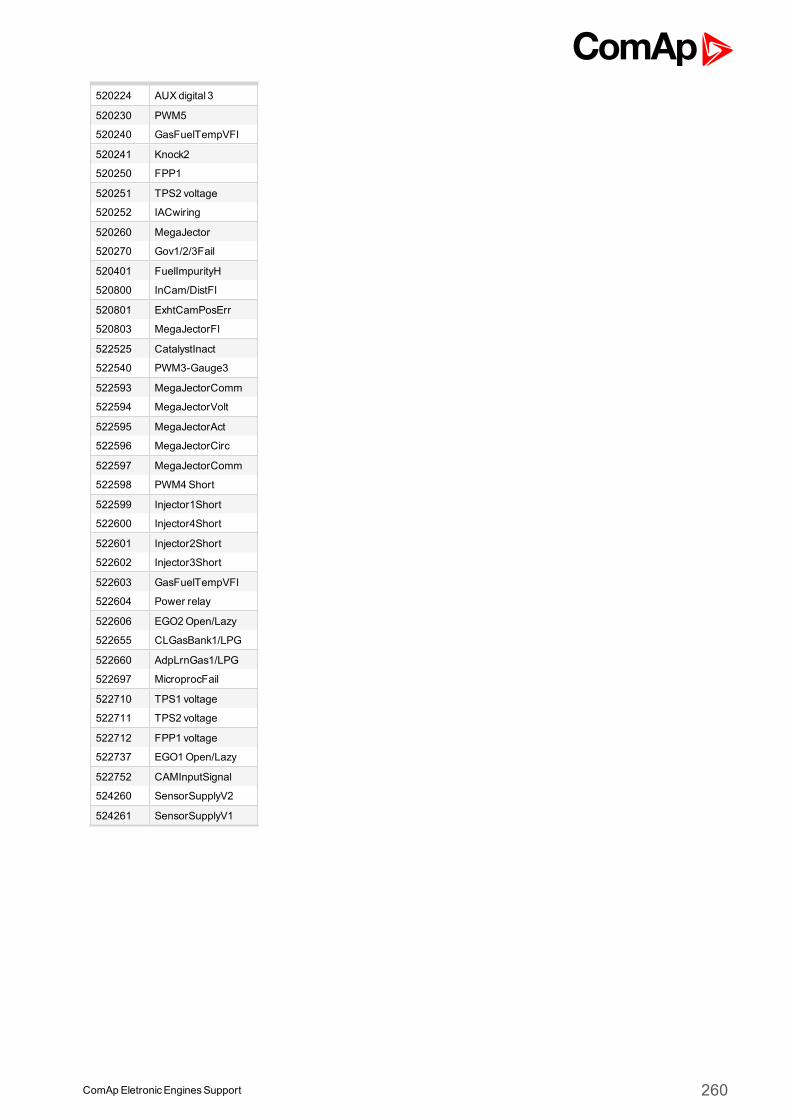
520224 AUXdigital 3
520230 PWM5
520240 GasFuelTempVFl
520241 Knock2
520250 FPP1
520251 TPS2 voltage
520252 IACwiring
520260 MegaJector
520270 Gov1/2/3Fail
520401 FuelImpurityH
520800 InCam/DistFl
520801 ExhtCamPosErr
520803 MegaJectorFl
522525 CatalystInact
522540 PWM3-Gauge3
522593 MegaJectorComm
522594 MegaJectorVolt
522595 MegaJectorAct
522596 MegaJectorCirc
522597 MegaJectorComm
522598 PWM4Short
522599 Injector1Short
522600 Injector4Short
522601 Injector2Short
522602 Injector3Short
522603 GasFuelTempVFl
522604 Power relay
522606 EGO2Open/Lazy
522655 CLGasBank1/LPG
522660 AdpLrnGas1/LPG
522697 MicroprocFail
522710 TPS1 voltage
522711 TPS2 voltage
522712 FPP1 voltage
522737 EGO1Open/Lazy
522752 CAMInputSignal
524260 SensorSupplyV2
524261 SensorSupplyV1
ComApEletronicEnginesSupport 260
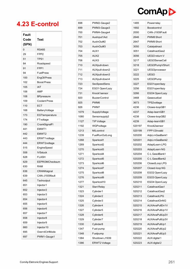
4.23 E-controlFaultCode(SPN)
Text
0 RS485
29 FPP2
51 TPS1
84 Roadspeed
91 FPP1
94 FuelPress
100 EngOil Press
102 Boost Press
105 IAT
106 AMP
108 BPpressure
109 Coolant Press
110 ECT
168 BatteryVoltage
173 EGTtemperature
174 FTvoltage
190 CrankSignalFl
441 EMWT1
442 EMWT2
443 ERWT1voltage
444 ERWT2voltage
515 EngineSpeed
558 IVSstuck
628 FLASH
629 EEPROMChecksum
630 RAM
636 CRANKsignal
639 CAN-J1939fault
645 Tachoutput
651 Injector1
652 Injector2
653 Injector3
654 Injector4
655 Injector5
656 Injector6
657 Injector7
658 Injector8
659 Injector9
660 Injector10
695 OverrdCtrlMode
697 PWM1-Gauge1
698 PWM2-Gauge2
699 PWM3-Gauge3
700 PWM4-Gauge4
701 AuxInput1Act
702 AuxInOut#2
703 AuxInOut#3
704 AUX1
705 AUX2
706 AUX3
710 AUXpull-down
711 AUXpull-down2
712 AUXpull-down3
713 AUXpull-down4
723 SecSpeedSens
724 EGO1Open/Lazy
731 Knock1sensor
920 BuzzerControl
925 PWM6
926 PWM7
1079 SupplyVoltage
1080 Sensorsupply2
1127 TIPVoltage
1192 WGPvoltage
1213 MILcontrol
1239 FuelRunOutLong
1268 Sparkcoil1
1269 Sparkcoil2
1270 Sparkcoil3
1271 Sparkcoil4
1272 Sparkcoil5
1273 Sparkcoil6
1274 Sparkcoil7
1275 Sparkcoil8
1276 Sparkcoil9
1277 Sparkcoil10
1321 Start Relay
1323 Cylinder1
1324 Cylinder2
1325 Cylinder3
1326 Cylinder4
1327 Cylinder5
1328 Cylinder6
1329 Cylinder7
1330 Cylinder8
1347 Fuel-pump
1348 Fuelpump
1384 Shutdown J1939
1386 ERWT2Voltage
1485 Powerrelay
1692 Boostcontrol
2000 CAN-J1939Fault
2646 PWM8Short
2647 PWM9Short
3050 Catalystinact
3051 CatalInactGas2
3056 UEGOreturn V
3217 UEGOSenseCell
3218 UEGOPumpVShort
3221 UEGOprocessor
3222 UEGO
3225 UEGOPump
3227 EGO1open/lazy
3256 EGO1open/lazy
3266 EGO4Open/Lazy
3468 Gaseousfuel
3673 TPS2voltage
4236 Closes-loopGB1
4237 Adap-learnGB1
4238 Closes-loopGB2
4239 Adap-learnGB1
520197 Knock2sensor
520199 FPP1/2Invalid
520200 AdpLrnGasBank1
520201 AdpLrnGasBank2
520202 AdaptLearn LPG
520203 AdaptLearn NG
520204 C-LGasolBank1
520205 C-LGasolBank2
520206 ClosedLoop LPG
520207 Closed-loop NG
520208 EGO2Open/Lazy
520209 EGO3Open/Lazy
520210 EGO4Open/Lazy
520211 CatalInactGas1
520212 CatalInactGas2
520213 CatalInactLPG
520214 CatalInactOnNG
520215 AUXAnaPullDn1V
520216 AUXAnaPullUp1V
520217 AUXAnaPullUp2V
520218 AUXAnaPullUp3V
520219 AUXAnaPullUp1
520220 AUXAnaPullUp2
520221 AUXAnaPullUp3
520222 AUXdigital 1
520223 AUXdigital 2
ComAp EletronicEnginesSupport 261

520224 AUXdigital 3
520230 PWM5
520240 GasFuelTempVFl
520241 Knock2
520250 FPP1
520251 TPS2 voltage
520252 IACwiring
520260 MegaJector
520270 Gov1/2/3Fail
520401 FuelImpurityH
520800 InCam/DistFl
520801 ExhtCamPosErr
520803 MegaJectorFl
522525 CatalystInact
522540 PWM3-Gauge3
522593 MegaJectorComm
522594 MegaJectorVolt
522595 MegaJectorAct
522596 MegaJectorCirc
522597 MegaJectorComm
522598 PWM4Short
522599 Injector1Short
522600 Injector4Short
522601 Injector2Short
522602 Injector3Short
522603 GasFuelTempVFl
522604 Power relay
522606 EGO2Open/Lazy
522655 CLGasBank1/LPG
522660 AdpLrnGas1/LPG
522697 MicroprocFail
522710 TPS1 voltage
522711 TPS2 voltage
522712 FPP1 voltage
522737 EGO1Open/Lazy
522752 CAMInputSignal
524260 SensorSupplyV2
524261 SensorSupplyV1
ComApEletronicEnginesSupport 262
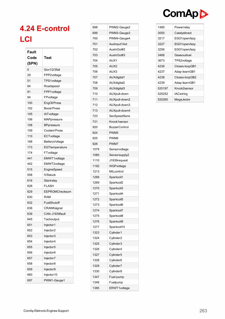
4.24 E-controlLCI
FaultCode(SPN)
Text
0 Gov1/2/3fail
29 FPP2voltage
51 TPS1voltage
84 Roadspeed
91 FPP1voltage
94 FPvoltage
100 EngOil Press
102 Boost Press
105 IATvoltage
106 MAPpressure
108 BPpressure
109 Coolant Press
110 ECTvoltage
168 BatteryVoltage
173 EGTtemperature
174 FTvoltage
441 EMWT1voltage
442 EMWT2voltage
515 EngineSpeed
558 IVSstuck
616 Startrelay
628 FLASH
629 EEPROMChecksum
630 RAM
632 FuelShutoff
636 CRANKsignal
639 CAN-J1939fault
645 Tachoutput
651 Injector1
652 Injector2
653 Injector3
654 Injector4
655 Injector5
656 Injector6
657 Injector7
658 Injector8
659 Injector9
660 Injector10
697 PWM1-Gauge1
698 PWM2-Gauge2
699 PWM3-Gauge3
700 PWM4-Gauge4
701 AuxInput1Act
702 AuxInOut#2
703 AuxInOut#3
704 AUX1
705 AUX2
706 AUX3
707 AUXdigital1
708 AUXdigital2
709 AUXdigital3
710 AUXpull-down
711 AUXpull-down2
712 AUXpull-down3
713 AUXpull-down4
723 SecSpeedSens
731 Knock1sensor
920 BuzzerControl
924 PWM5
925 PWM6
926 PWM7
1079 Sensorvoltage
1080 Sensorsupply2
1110 J1939request
1192 WGPvoltage
1213 MILcontrol
1268 Sparkcoil1
1269 Sparkcoil2
1270 Sparkcoil3
1271 Sparkcoil4
1272 Sparkcoil5
1273 Sparkcoil6
1274 Sparkcoil7
1275 Sparkcoil8
1276 Sparkcoil9
1277 Sparkcoil10
1323 Cylinder1
1324 Cylinder2
1325 Cylinder3
1326 Cylinder4
1327 Cylinder5
1328 Cylinder6
1329 Cylinder7
1330 Cylinder8
1347 Fuel-pump
1348 Fuelpump
1385 ERWT1voltage
1485 Powerrelay
3050 Catalystinact
3217 EGO1open/lazy
3227 EGO1open/lazy
3256 EGO1open/lazy
3468 Gaseousfuel
3673 TPS2voltage
4236 Closes-loopGB1
4237 Adap-learnGB1
4238 Closes-loopGB2
4239 Adap-learnGB1
520197 Knock2sensor
520252 IACwiring
520260 MegaJector
ComAp EletronicEnginesSupport 263
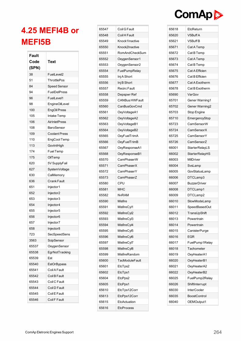
4.25 MEFI4B orMEFI5B
FaultCode(SPN)
Text
38 FuelLevel2
51 ThrottlePos
84 Speed Sensor
94 FuelDelPress
96 FuelLevel1
98 EngineOilLevel
100 EngOil Press
105 Intake Temp
106 AirInletPress
108 BaroSensor
109 Coolant Press
110 EngCool Temp
113 GovIntHigh
174 Fuel Temp
175 OilTemp
620 5VSupplyFail
627 SystemVoltage
630 CalMemory
636 CrankFault
651 Injector1
652 Injector2
653 Injector3
654 Injector4
655 Injector5
656 Injector6
657 Injector7
658 Injector8
723 SecSpeedSens
3563 ScipSensor
65537 OxygenSensor
65538 EgrNotTracking
65539 Est
65540 EstOrBypass
65541 Coil A Fault
65542 Coil B Fault
65543 CoilC Fault
65544 CoilD Fault
65545 Coil E Fault
65546 Coil F Fault
65547 CoilGFault
65548 CoilH Fault
65549 Knock1Inactive
65550 Knock2Inactive
65551 RomAndCheckSum
65552 OxygenSensor1
65553 OxygenSensor2
65554 FuelPumpRelay
65555 InjA Short
65556 InjB Short
65557 RecircFault
65558 Depspwr Ref
65559 CANBusHWFault
65560 CanBusGovCmd
65561 OxyVoltageA1
65562 OxyVoltageA2
65563 OxyVoltageB1
65564 OxyVoltageB2
65565 OxyFuelTrimA
65566 OxyFuelTrimB
65567 OxyResponseA1
65568 OxyResponseB1
65570 CamPhaserW
65571 CamPhaserX
65572 CamPhaserY
65573 CamPhaserZ
65580 CPU
65581 MHC
65582 NvRAM
65590 Misfire
65591 MisfireCyl1
65592 MisfireCyl2
65593 MisfireCyl3
65594 MisfireCyl4
65595 MisfireCyl5
65596 MisfireCyl6
65597 MisfireCyl7
65598 MisfireCyl8
65599 MisfireRandom
65600 TacModuleFault
65601 EtcTps2
65602 EtcTps1
65604 EtcPps2
65605 EtcPps1
65610 EtcTps12Corr
65613 EtcPps12Corr
65615 EtcActuation
65616 EtcProcess
65618 EtcReturn
65620 V5Buff A
65621 V5Buff B
65671 Cat A Temp
65672 Cat B Temp
65673 Cat A Temp
65674 Cat B Temp
65675 Cat AEfficien
65676 Cat BEfficien
65677 Cat AExotherm
65678 Cat BExotherm
65690 VarGov
65701 Gener Warning1
65702 Gener Warning2
65703 Stop Engine
65710 EmergencyStop
65723 CamSensorW
65724 CamSensorX
65725 CamSensorY
65726 CamSensorZ
66001 StarterRelayLS
66002 StarterRelayHS
66003 MilDriver
66004 SvsLamp
66005 GovStatusLamp
66006 DTCLamp3
66007 BuzzerDriver
66008 DTCLamp1
66009 DTCLamp2
66010 SlowModeLamp
66011 SpeedBasedOut
66012 TransUpShift
66013 Powertrain
66014 Powertrain
66015 CanisterPurge
66016 EGR
66017 FuelPump1Relay
66018 Tachometer
66019 OxyHeaterA1
66020 OxyHeaterB1
66021 OxyHeaterA2
66022 OxyHeaterB2
66025 FuelPump2Relay
66026 ShiftInterrupt
66030 InterCooler
66035 BoostControl
66040 OEMOutput1
ComApEletronicEnginesSupport 264
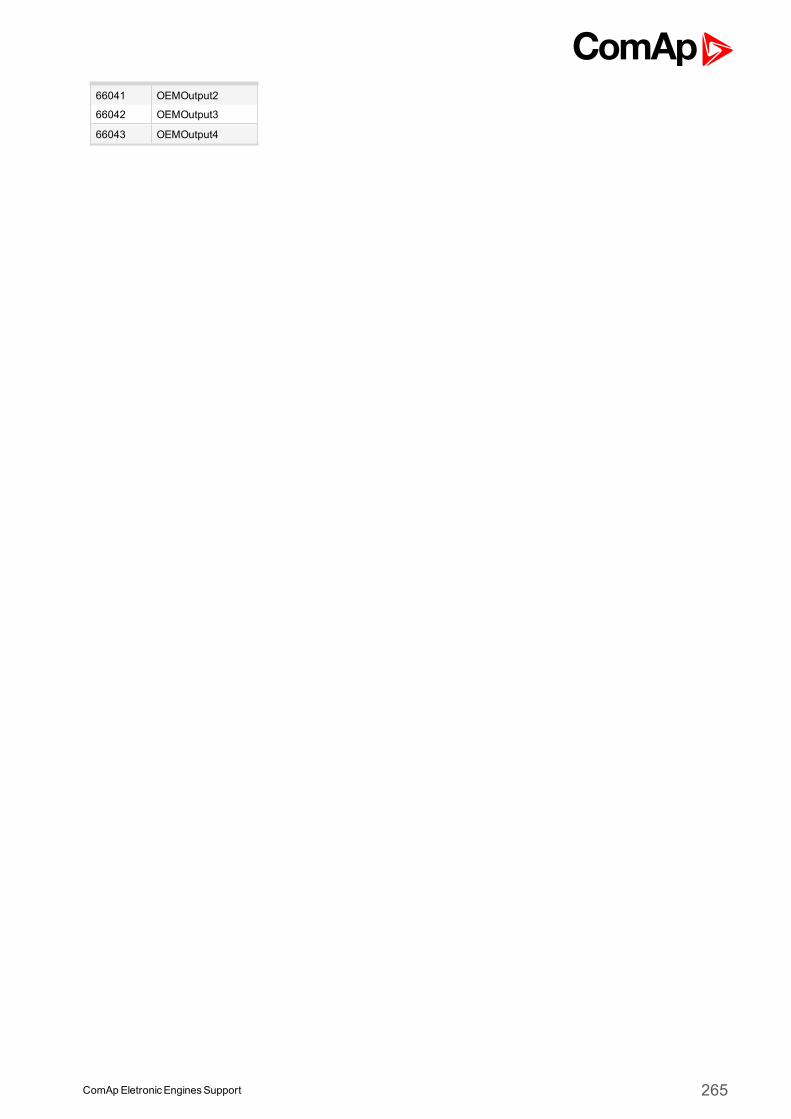
66041 OEMOutput2
66042 OEMOutput3
66043 OEMOutput4
ComApEletronicEnginesSupport 265
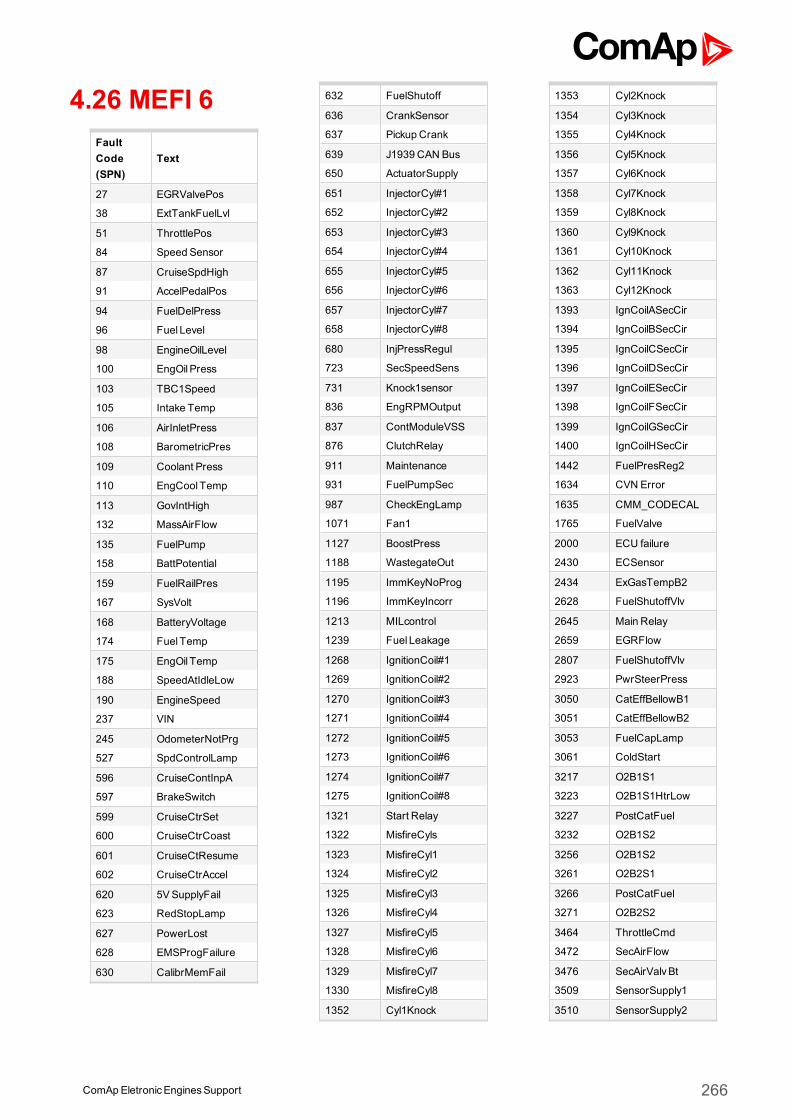
4.26 MEFI 6FaultCode(SPN)
Text
27 EGRValvePos
38 ExtTankFuelLvl
51 ThrottlePos
84 Speed Sensor
87 CruiseSpdHigh
91 AccelPedalPos
94 FuelDelPress
96 Fuel Level
98 EngineOilLevel
100 EngOil Press
103 TBC1Speed
105 Intake Temp
106 AirInletPress
108 BarometricPres
109 Coolant Press
110 EngCool Temp
113 GovIntHigh
132 MassAirFlow
135 FuelPump
158 BattPotential
159 FuelRailPres
167 SysVolt
168 BatteryVoltage
174 Fuel Temp
175 EngOil Temp
188 SpeedAtIdleLow
190 EngineSpeed
237 VIN
245 OdometerNotPrg
527 SpdControlLamp
596 CruiseContInpA
597 BrakeSwitch
599 CruiseCtrSet
600 CruiseCtrCoast
601 CruiseCtResume
602 CruiseCtrAccel
620 5VSupplyFail
623 RedStopLamp
627 PowerLost
628 EMSProgFailure
630 CalibrMemFail
632 FuelShutoff
636 CrankSensor
637 Pickup Crank
639 J1939 CAN Bus
650 ActuatorSupply
651 InjectorCyl#1
652 InjectorCyl#2
653 InjectorCyl#3
654 InjectorCyl#4
655 InjectorCyl#5
656 InjectorCyl#6
657 InjectorCyl#7
658 InjectorCyl#8
680 InjPressRegul
723 SecSpeedSens
731 Knock1sensor
836 EngRPMOutput
837 ContModuleVSS
876 ClutchRelay
911 Maintenance
931 FuelPumpSec
987 CheckEngLamp
1071 Fan1
1127 BoostPress
1188 WastegateOut
1195 ImmKeyNoProg
1196 ImmKeyIncorr
1213 MILcontrol
1239 Fuel Leakage
1268 IgnitionCoil#1
1269 IgnitionCoil#2
1270 IgnitionCoil#3
1271 IgnitionCoil#4
1272 IgnitionCoil#5
1273 IgnitionCoil#6
1274 IgnitionCoil#7
1275 IgnitionCoil#8
1321 Start Relay
1322 MisfireCyls
1323 MisfireCyl1
1324 MisfireCyl2
1325 MisfireCyl3
1326 MisfireCyl4
1327 MisfireCyl5
1328 MisfireCyl6
1329 MisfireCyl7
1330 MisfireCyl8
1352 Cyl1Knock
1353 Cyl2Knock
1354 Cyl3Knock
1355 Cyl4Knock
1356 Cyl5Knock
1357 Cyl6Knock
1358 Cyl7Knock
1359 Cyl8Knock
1360 Cyl9Knock
1361 Cyl10Knock
1362 Cyl11Knock
1363 Cyl12Knock
1393 IgnCoilASecCir
1394 IgnCoilBSecCir
1395 IgnCoilCSecCir
1396 IgnCoilDSecCir
1397 IgnCoilESecCir
1398 IgnCoilFSecCir
1399 IgnCoilGSecCir
1400 IgnCoilHSecCir
1442 FuelPresReg2
1634 CVN Error
1635 CMM_CODECAL
1765 FuelValve
2000 ECU failure
2430 ECSensor
2434 ExGasTempB2
2628 FuelShutoffVlv
2645 Main Relay
2659 EGRFlow
2807 FuelShutoffVlv
2923 PwrSteerPress
3050 CatEffBellowB1
3051 CatEffBellowB2
3053 FuelCapLamp
3061 ColdStart
3217 O2B1S1
3223 O2B1S1HtrLow
3227 PostCatFuel
3232 O2B1S2
3256 O2B1S2
3261 O2B2S1
3266 PostCatFuel
3271 O2B2S2
3464 ThrottleCmd
3472 SecAirFlow
3476 SecAirValvBt
3509 SensorSupply1
3510 SensorSupply2
ComApEletronicEnginesSupport 266
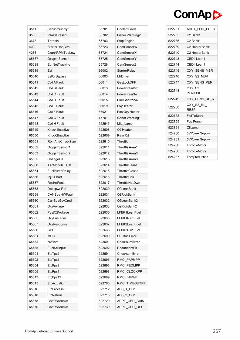
3511 SensorSupply3
3563 IntakePress1
3673 Throttle
4002 StarterReqCirc
4256 CrankRPMTooLow
65537 OxygenSensor
65538 EgrNotTracking
65539 Est
65540 EstOrBypass
65541 Coil A Fault
65542 Coil B Fault
65543 CoilC Fault
65544 CoilD Fault
65545 Coil E Fault
65546 Coil F Fault
65547 CoilGFault
65548 CoilH Fault
65549 Knock1Inactive
65550 Knock2Inactive
65551 RomAndCheckSum
65552 OxygenSensor1
65553 OxygenSensor2
65555 ChangeOil
65600 TacModuleFault
65554 FuelPumpRelay
65556 InjB Short
65557 RecircFault
65558 Depspwr Ref
65559 CANBusHWFault
65560 CanBusGovCmd
65561 OxyVoltage
65562 PostO2Voltage
65565 OxyFuelTrim
65567 OxyResponse
65580 CPU
65581 MHC
65582 NvRam
65585 FuelSelInput
65601 EtcTps2
65602 EtcTps1
65604 EtcPps2
65605 EtcPps1
65613 EtcPps12
65615 EtcActuation
65616 EtcProcess
65618 EtcReturn
65675 CatEfficiencyA
65676 CatEfficiencyB
65701 CoolantLevel
65702 Gener Warning2
65703 Stop Engine
65723 CamSensorW
65724 CamSensorX
65725 CamSensorY
65728 CamSensorZ
66002 StarterRelay
66003 MilDriver
66011 GasLockOFF
66013 PowertrainDrr
66014 PowertrainSw
66015 FuelControlVlv
66019 OxyHeater
66021 PostOxyHeater
75701 Gener Warning1
522545 MIL_Lamp
522608 O2Heater
522609 Rear O2
522610 Throttle
522611 Throttle Area1
522612 Throttle Area3
522613 Throttle Area3
522614 ThrottleFailed
522615 ThrottleClosed
522616 ThrottlePos
522617 ThrottleNotDwn
522630 O2LeanBank1
522631 O2RichBank1
522632 O2LeanBank2
522633 O2RichBank2
522635 LFBK1LeanFuel
522636 LFBK1RichFuel
522637 LFBK2LeanFuel
522638 LFBK2RichFuel
522690 SPI BusError
522691 ChecksumError
522692 RedundantFlt
522694 ChecksumError
522695 RMC_PAPMPP
522696 RMC_PEDMPP
522698 RMC_CLOCKPP
522699 RMC_INHWP
522700 RMC_TIMEOUTPP
522712 APS_1_CC1
522713 APS_2_CC1
522729 ADPT_OBD_GAIN
522730 ADPT_OBD_OFF
522731 ADPT_OBD_PRES
522735 O2 Bank1
522736 O2 Bank1
522739 O2HeaterBank1
522740 O2HeaterBank1
522743 OBDII Lean1
522744 OBDII Lean1
522745 OXY_SENS_MSR
522746 OXY_S2_MSR
522747 OXY_SENS_PER
522748OXY_S2_PERIODE
522749 OXY_SENS_RL_R
522750OXY_S2_RL_RESP
522752 FailToStart
522755 FuelPump
523821 OilLamp
524260 5VPowerSupply
524261 5VPowerSupply
524266 ThrottleMotor
524286 ThrottleMotor
524287 TorqReduction
ComApEletronicEnginesSupport 267
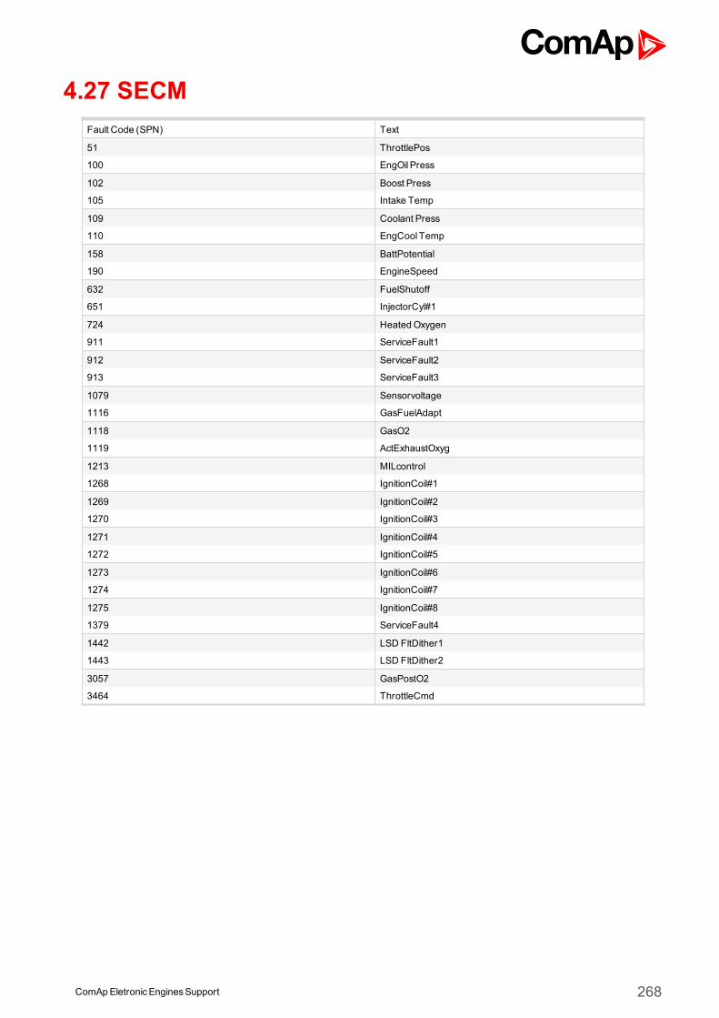
ComApEletronicEnginesSupport 268
4.27 SECMFault Code (SPN) Text
51 ThrottlePos
100 EngOil Press
102 Boost Press
105 Intake Temp
109 Coolant Press
110 EngCool Temp
158 BattPotential
190 EngineSpeed
632 FuelShutoff
651 InjectorCyl#1
724 HeatedOxygen
911 ServiceFault1
912 ServiceFault2
913 ServiceFault3
1079 Sensorvoltage
1116 GasFuelAdapt
1118 GasO2
1119 ActExhaustOxyg
1213 MILcontrol
1268 IgnitionCoil#1
1269 IgnitionCoil#2
1270 IgnitionCoil#3
1271 IgnitionCoil#4
1272 IgnitionCoil#5
1273 IgnitionCoil#6
1274 IgnitionCoil#7
1275 IgnitionCoil#8
1379 ServiceFault4
1442 LSD FltDither1
1443 LSD FltDither2
3057 GasPostO2
3464 ThrottleCmd
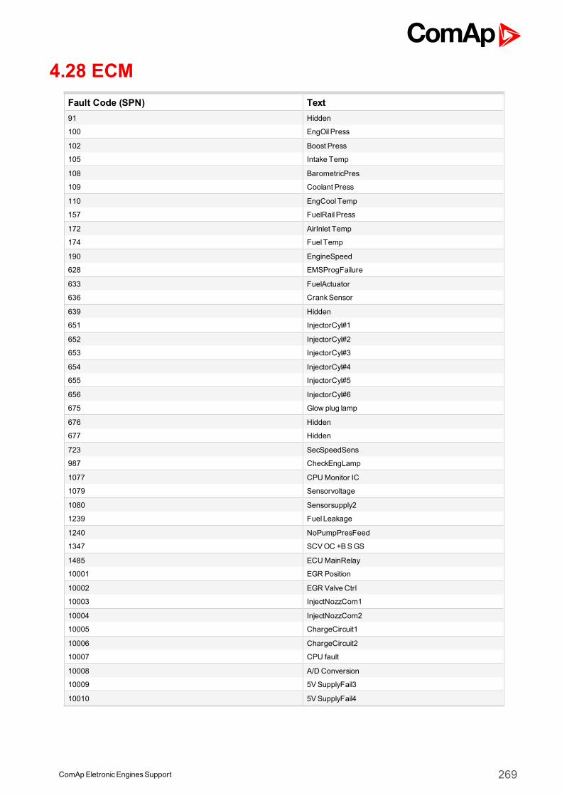
ComApEletronicEnginesSupport 269
4.28 ECMFault Code (SPN) Text91 Hidden
100 EngOil Press
102 Boost Press
105 Intake Temp
108 BarometricPres
109 Coolant Press
110 EngCool Temp
157 FuelRail Press
172 AirInlet Temp
174 Fuel Temp
190 EngineSpeed
628 EMSProgFailure
633 FuelActuator
636 CrankSensor
639 Hidden
651 InjectorCyl#1
652 InjectorCyl#2
653 InjectorCyl#3
654 InjectorCyl#4
655 InjectorCyl#5
656 InjectorCyl#6
675 Glow plug lamp
676 Hidden
677 Hidden
723 SecSpeedSens
987 CheckEngLamp
1077 CPUMonitor IC
1079 Sensorvoltage
1080 Sensorsupply2
1239 Fuel Leakage
1240 NoPumpPresFeed
1347 SCVOC +BSGS
1485 ECUMainRelay
10001 EGR Position
10002 EGR Valve Ctrl
10003 InjectNozzCom1
10004 InjectNozzCom2
10005 ChargeCircuit1
10006 ChargeCircuit2
10007 CPU fault
10008 A/D Conversion
10009 5VSupplyFail3
10010 5VSupplyFail4
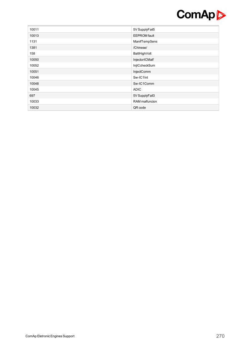
ComApEletronicEnginesSupport 270
10011 5VSupplyFail5
10013 EEPROM fault
1131 ManifTempSens
1381 /Chinese/
158 BattHighVolt
10050 InjectorICMalf
10052 InjICcheckSum
10051 InjectComm
10046 Sw-IC1Int
10048 Sw-IC1Comm
10045 ADIC
697 5VSupplyFail3
10033 RAMmalfuncion
10032 QR code
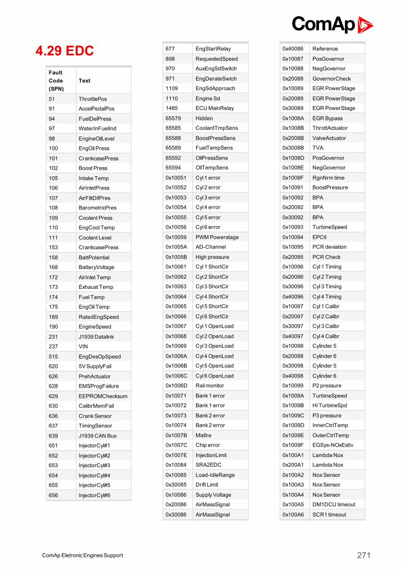
4.29 EDCFaultCode(SPN)
Text
51 ThrottlePos
91 AccelPedalPos
94 FuelDelPress
97 WaterInFuelInd
98 EngineOilLevel
100 EngOil Press
101 CrankcasePress
102 Boost Press
105 Intake Temp
106 AirInletPress
107 AirFiltDifPres
108 BarometricPres
109 Coolant Press
110 EngCool Temp
111 Coolant Level
153 CrankcasePress
158 BattPotential
168 BatteryVoltage
172 AirInlet Temp
173 Exhaust Temp
174 Fuel Temp
175 EngOil Temp
189 RatedEngSpeed
190 EngineSpeed
231 J1939 Datalink
237 VIN
515 EngDesOpSpeed
620 5VSupplyFail
626 PrehActuator
628 EMSProgFailure
629 EEPROMChecksum
630 CalibrMemFail
636 CrankSensor
637 TimingSensor
639 J1939 CAN Bus
651 InjectorCyl#1
652 InjectorCyl#2
653 InjectorCyl#3
654 InjectorCyl#4
655 InjectorCyl#5
656 InjectorCyl#6
677 EngStartRelay
898 RequestedSpeed
970 AuxEngSdSwitch
971 EngDerateSwtch
1109 EngSdApproach
1110 Engine Sd
1485 ECUMainRelay
65579 Hidden
65585 CoolantTmpSens
65588 BoostPressSens
65589 FuelTempSens
65592 OilPressSens
65594 OilTempSens
0x10051 Cyl 1 error
0x10052 Cyl 2 error
0x10053 Cyl 3 error
0x10054 Cyl 4 error
0x10055 Cyl 5 error
0x10056 Cyl 6 error
0x10059 PWMPowerstage
0x1005A AD-Channel
0x1005B High pressure
0x10061 Cyl 1 ShortCir
0x10062 Cyl 2 ShortCir
0x10063 Cyl 3 ShortCir
0x10064 Cyl 4 ShortCir
0x10065 Cyl 5 ShortCir
0x10066 Cyl 6 ShortCir
0x10067 Cyl 1 OpenLoad
0x10068 Cyl 2 OpenLoad
0x10069 Cyl 3 OpenLoad
0x1006A Cyl 4 OpenLoad
0x1006B Cyl 5 OpenLoad
0x1006C Cyl 6 OpenLoad
0x1006D Railmonitor
0x10071 Bank1 error
0x10072 Bank1 error
0x10073 Bank2 error
0x10074 Bank2 error
0x1007B Misfire
0x1007C Chip error
0x1007E InjectionLimit
0x10084 SRA2EDC
0x10085 Load-IdleRange
0x30085 Drift Limit
0x10086 SupplyVoltage
0x20086 AirMassSignal
0x30086 AirMassSignal
0x40086 Reference
0x10087 PosGovernor
0x10088 NegGovernor
0x20088 GovernorCheck
0x10089 EGR PowerStage
0x20089 EGR PowerStage
0x30089 EGR PowerStage
0x1008A EGR Bypass
0x1008B ThrottActuator
0x2008B ValveActuator
0x3008B TVA
0x1008D PosGovernor
0x1008E NegGovernor
0x1008F RgnNrm time
0x10091 BoostPressure
0x10092 BPA
0x20092 BPA
0x30092 BPA
0x10093 TurbineSpeed
0x10094 EPCtl
0x10095 PCR deviation
0x20095 PCR Check
0x10096 Cyl 1 Timing
0x20096 Cyl 2 Timing
0x30096 Cyl 3 Timing
0x40096 Cyl 4 Timing
0x10097 Cyl 1 Calibr
0x20097 Cyl 2 Calibr
0x30097 Cyl 3 Calibr
0x40097 Cyl 4 Calibr
0x10098 Cylinder 5
0x20098 Cylinder 6
0x30098 Cylinder 5
0x40098 Cylinder 6
0x10099 P2 pressure
0x1009A TurbineSpeed
0x1009B HiTurbineSpd
0x1009C P3 pressure
0x1009D InnerCtrlTemp
0x1009E OuterCtrlTemp
0x1009F EGSys-NOxEstIv
0x100A1 LambdaNox
0x200A1 LambdaNox
0x100A2 NoxSensor
0x100A3 NoxSensor
0x100A4 NoxSensor
0x100A5 DM1DCU timeout
0x100A6 SCR1 timeout
ComAp EletronicEnginesSupport 271
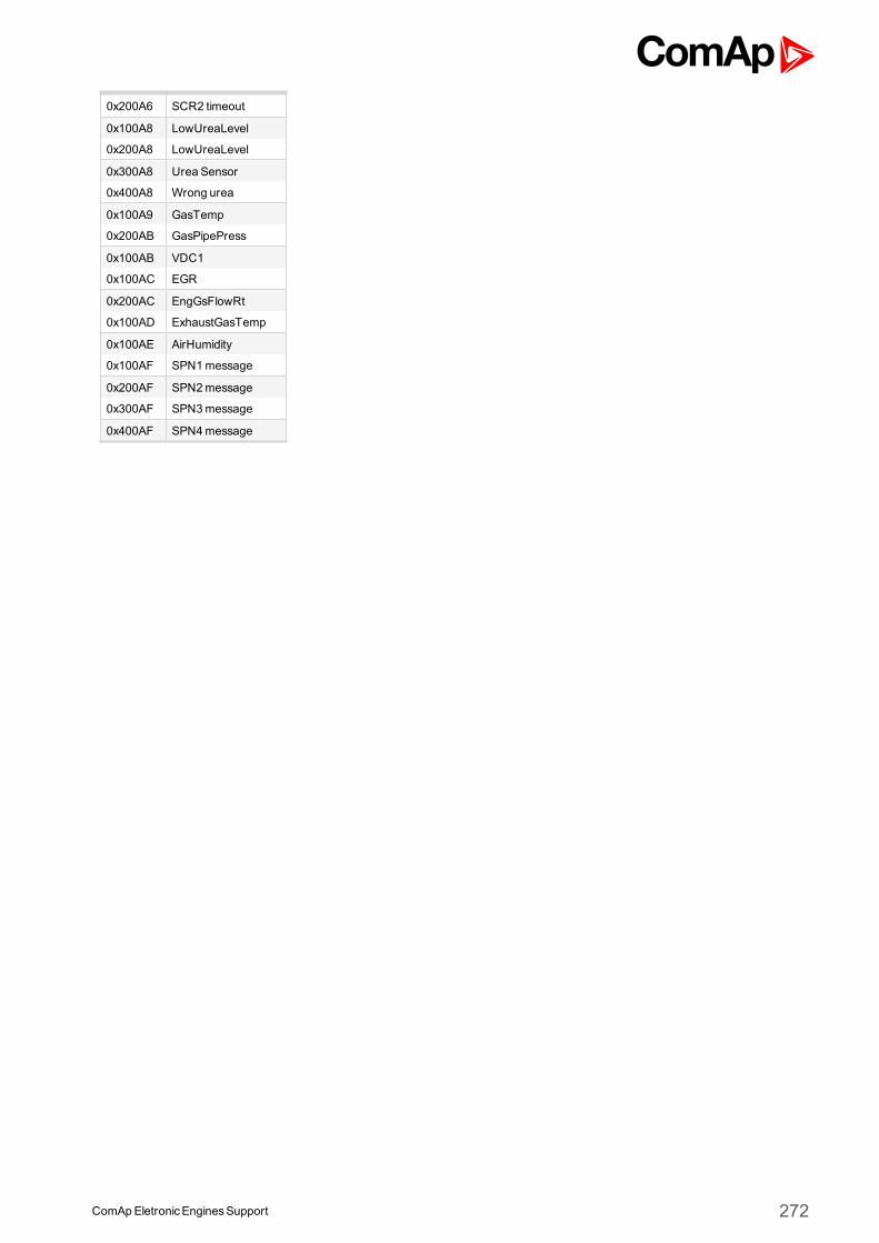
0x200A6 SCR2 timeout
0x100A8 LowUreaLevel
0x200A8 LowUreaLevel
0x300A8 Urea Sensor
0x400A8 Wrong urea
0x100A9 GasTemp
0x200AB GasPipePress
0x100AB VDC1
0x100AC EGR
0x200AC EngGsFlowRt
0x100AD ExhaustGasTemp
0x100AE AirHumidity
0x100AF SPN1message
0x200AF SPN2message
0x300AF SPN3message
0x400AF SPN4message
ComApEletronicEnginesSupport 272
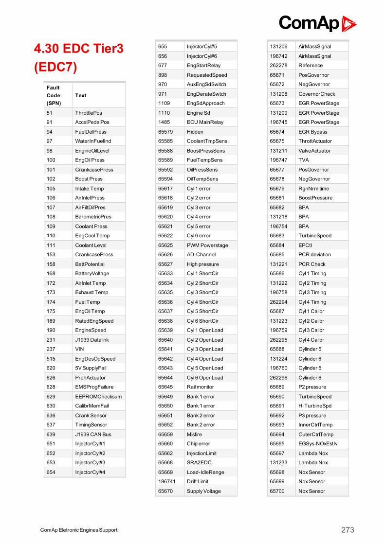
4.30 EDC Tier3(EDC7)
FaultCode(SPN)
Text
51 ThrottlePos
91 AccelPedalPos
94 FuelDelPress
97 WaterInFuelInd
98 EngineOilLevel
100 EngOil Press
101 CrankcasePress
102 Boost Press
105 Intake Temp
106 AirInletPress
107 AirFiltDifPres
108 BarometricPres
109 Coolant Press
110 EngCool Temp
111 Coolant Level
153 CrankcasePress
158 BattPotential
168 BatteryVoltage
172 AirInlet Temp
173 Exhaust Temp
174 Fuel Temp
175 EngOil Temp
189 RatedEngSpeed
190 EngineSpeed
231 J1939 Datalink
237 VIN
515 EngDesOpSpeed
620 5VSupplyFail
626 PrehActuator
628 EMSProgFailure
629 EEPROMChecksum
630 CalibrMemFail
636 CrankSensor
637 TimingSensor
639 J1939 CAN Bus
651 InjectorCyl#1
652 InjectorCyl#2
653 InjectorCyl#3
654 InjectorCyl#4
655 InjectorCyl#5
656 InjectorCyl#6
677 EngStartRelay
898 RequestedSpeed
970 AuxEngSdSwitch
971 EngDerateSwtch
1109 EngSdApproach
1110 Engine Sd
1485 ECUMainRelay
65579 Hidden
65585 CoolantTmpSens
65588 BoostPressSens
65589 FuelTempSens
65592 OilPressSens
65594 OilTempSens
65617 Cyl 1 error
65618 Cyl 2 error
65619 Cyl 3 error
65620 Cyl 4 error
65621 Cyl 5 error
65622 Cyl 6 error
65625 PWMPowerstage
65626 AD-Channel
65627 High pressure
65633 Cyl 1 ShortCir
65634 Cyl 2 ShortCir
65635 Cyl 3 ShortCir
65636 Cyl 4 ShortCir
65637 Cyl 5 ShortCir
65638 Cyl 6 ShortCir
65639 Cyl 1 OpenLoad
65640 Cyl 2 OpenLoad
65641 Cyl 3 OpenLoad
65642 Cyl 4 OpenLoad
65643 Cyl 5 OpenLoad
65644 Cyl 6 OpenLoad
65645 Railmonitor
65649 Bank1 error
65650 Bank1 error
65651 Bank2 error
65652 Bank2 error
65659 Misfire
65660 Chip error
65662 InjectionLimit
65668 SRA2EDC
65669 Load-IdleRange
196741 Drift Limit
65670 SupplyVoltage
131206 AirMassSignal
196742 AirMassSignal
262278 Reference
65671 PosGovernor
65672 NegGovernor
131208 GovernorCheck
65673 EGR PowerStage
131209 EGR PowerStage
196745 EGR PowerStage
65674 EGR Bypass
65675 ThrottActuator
131211 ValveActuator
196747 TVA
65677 PosGovernor
65678 NegGovernor
65679 RgnNrm time
65681 BoostPressure
65682 BPA
131218 BPA
196754 BPA
65683 TurbineSpeed
65684 EPCtl
65685 PCR deviation
131221 PCR Check
65686 Cyl 1 Timing
131222 Cyl 2 Timing
196758 Cyl 3 Timing
262294 Cyl 4 Timing
65687 Cyl 1 Calibr
131223 Cyl 2 Calibr
196759 Cyl 3 Calibr
262295 Cyl 4 Calibr
65688 Cylinder 5
131224 Cylinder 6
196760 Cylinder 5
262296 Cylinder 6
65689 P2 pressure
65690 TurbineSpeed
65691 HiTurbineSpd
65692 P3 pressure
65693 InnerCtrlTemp
65694 OuterCtrlTemp
65695 EGSys-NOxEstIv
65697 LambdaNox
131233 LambdaNox
65698 NoxSensor
65699 NoxSensor
65700 NoxSensor
ComAp EletronicEnginesSupport 273
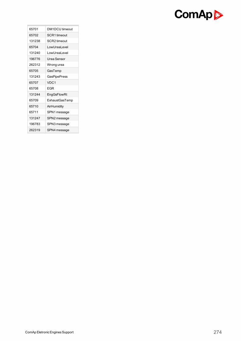
65701 DM1DCU timeout
65702 SCR1 timeout
131238 SCR2 timeout
65704 LowUreaLevel
131240 LowUreaLevel
196776 Urea Sensor
262312 Wrong urea
65705 GasTemp
131243 GasPipePress
65707 VDC1
65708 EGR
131244 EngGsFlowRt
65709 ExhaustGasTemp
65710 AirHumidity
65711 SPN1message
131247 SPN2message
196783 SPN3message
262319 SPN4message
ComApEletronicEnginesSupport 274
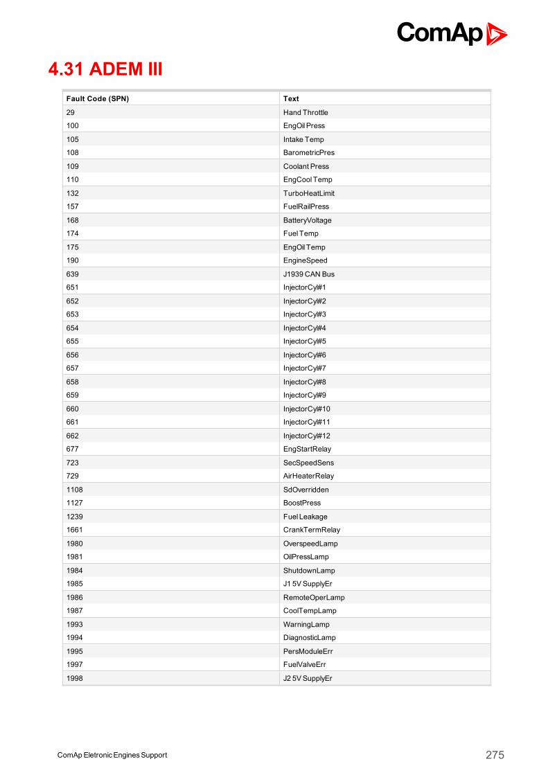
ComApEletronicEnginesSupport 275
4.31 ADEM IIIFault Code (SPN) Text
29 Hand Throttle
100 EngOil Press
105 Intake Temp
108 BarometricPres
109 Coolant Press
110 EngCool Temp
132 TurboHeatLimit
157 FuelRailPress
168 BatteryVoltage
174 Fuel Temp
175 EngOil Temp
190 EngineSpeed
639 J1939 CAN Bus
651 InjectorCyl#1
652 InjectorCyl#2
653 InjectorCyl#3
654 InjectorCyl#4
655 InjectorCyl#5
656 InjectorCyl#6
657 InjectorCyl#7
658 InjectorCyl#8
659 InjectorCyl#9
660 InjectorCyl#10
661 InjectorCyl#11
662 InjectorCyl#12
677 EngStartRelay
723 SecSpeedSens
729 AirHeaterRelay
1108 SdOverridden
1127 BoostPress
1239 Fuel Leakage
1661 CrankTermRelay
1980 OverspeedLamp
1981 OilPressLamp
1984 ShutdownLamp
1985 J1 5VSupplyEr
1986 RemoteOperLamp
1987 CoolTempLamp
1993 WarningLamp
1994 DiagnosticLamp
1995 PersModuleErr
1997 FuelValveErr
1998 J2 5VSupplyEr
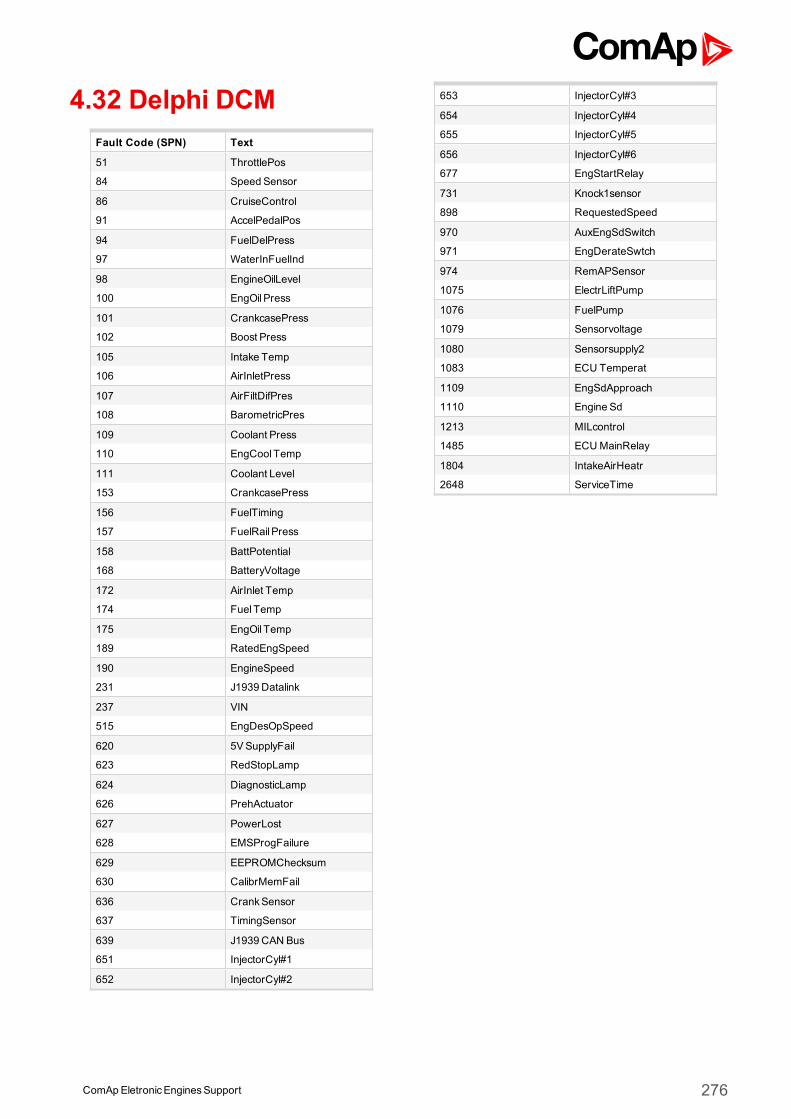
4.32 Delphi DCMFault Code (SPN) Text
51 ThrottlePos
84 Speed Sensor
86 CruiseControl
91 AccelPedalPos
94 FuelDelPress
97 WaterInFuelInd
98 EngineOilLevel
100 EngOil Press
101 CrankcasePress
102 Boost Press
105 Intake Temp
106 AirInletPress
107 AirFiltDifPres
108 BarometricPres
109 Coolant Press
110 EngCool Temp
111 Coolant Level
153 CrankcasePress
156 FuelTiming
157 FuelRail Press
158 BattPotential
168 BatteryVoltage
172 AirInlet Temp
174 Fuel Temp
175 EngOil Temp
189 RatedEngSpeed
190 EngineSpeed
231 J1939 Datalink
237 VIN
515 EngDesOpSpeed
620 5VSupplyFail
623 RedStopLamp
624 DiagnosticLamp
626 PrehActuator
627 PowerLost
628 EMSProgFailure
629 EEPROMChecksum
630 CalibrMemFail
636 CrankSensor
637 TimingSensor
639 J1939 CAN Bus
651 InjectorCyl#1
652 InjectorCyl#2
653 InjectorCyl#3
654 InjectorCyl#4
655 InjectorCyl#5
656 InjectorCyl#6
677 EngStartRelay
731 Knock1sensor
898 RequestedSpeed
970 AuxEngSdSwitch
971 EngDerateSwtch
974 RemAPSensor
1075 ElectrLiftPump
1076 FuelPump
1079 Sensorvoltage
1080 Sensorsupply2
1083 ECU Temperat
1109 EngSdApproach
1110 Engine Sd
1213 MILcontrol
1485 ECUMainRelay
1804 IntakeAirHeatr
2648 ServiceTime
ComApEletronicEnginesSupport 276
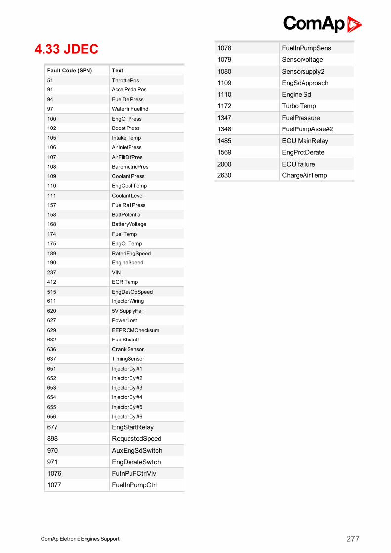
4.33 JDECFault Code (SPN) Text
51 ThrottlePos
91 AccelPedalPos
94 FuelDelPress
97 WaterInFuelInd
100 EngOil Press
102 Boost Press
105 Intake Temp
106 AirInletPress
107 AirFiltDifPres
108 BarometricPres
109 Coolant Press
110 EngCool Temp
111 Coolant Level
157 FuelRail Press
158 BattPotential
168 BatteryVoltage
174 Fuel Temp
175 EngOil Temp
189 RatedEngSpeed
190 EngineSpeed
237 VIN
412 EGR Temp
515 EngDesOpSpeed
611 InjectorWiring
620 5VSupplyFail
627 PowerLost
629 EEPROMChecksum
632 FuelShutoff
636 CrankSensor
637 TimingSensor
651 InjectorCyl#1
652 InjectorCyl#2
653 InjectorCyl#3
654 InjectorCyl#4
655 InjectorCyl#5
656 InjectorCyl#6
677 EngStartRelay
898 RequestedSpeed
970 AuxEngSdSwitch
971 EngDerateSwtch
1076 FuInPuFCtrlVlv
1077 FuelInPumpCtrl
1078 FuelInPumpSens
1079 Sensorvoltage
1080 Sensorsupply2
1109 EngSdApproach
1110 Engine Sd
1172 Turbo Temp
1347 FuelPressure
1348 FuelPumpAsse#2
1485 ECU MainRelay
1569 EngProtDerate
2000 ECU failure
2630 ChargeAirTemp
ComApEletronicEnginesSupport 277
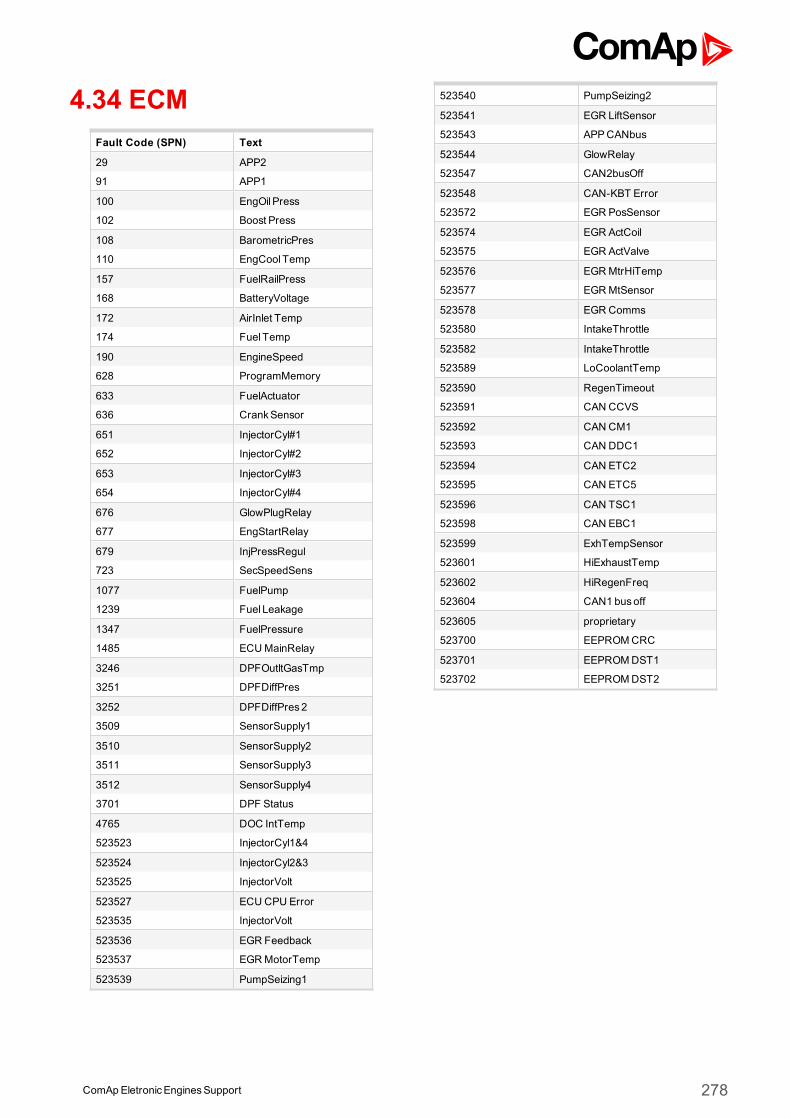
4.34 ECMFault Code (SPN) Text
29 APP2
91 APP1
100 EngOil Press
102 Boost Press
108 BarometricPres
110 EngCool Temp
157 FuelRailPress
168 BatteryVoltage
172 AirInlet Temp
174 Fuel Temp
190 EngineSpeed
628 ProgramMemory
633 FuelActuator
636 CrankSensor
651 InjectorCyl#1
652 InjectorCyl#2
653 InjectorCyl#3
654 InjectorCyl#4
676 GlowPlugRelay
677 EngStartRelay
679 InjPressRegul
723 SecSpeedSens
1077 FuelPump
1239 Fuel Leakage
1347 FuelPressure
1485 ECUMainRelay
3246 DPFOutltGasTmp
3251 DPFDiffPres
3252 DPFDiffPres2
3509 SensorSupply1
3510 SensorSupply2
3511 SensorSupply3
3512 SensorSupply4
3701 DPF Status
4765 DOC IntTemp
523523 InjectorCyl1&4
523524 InjectorCyl2&3
523525 InjectorVolt
523527 ECU CPU Error
523535 InjectorVolt
523536 EGR Feedback
523537 EGRMotorTemp
523539 PumpSeizing1
523540 PumpSeizing2
523541 EGR LiftSensor
523543 APPCANbus
523544 GlowRelay
523547 CAN2busOff
523548 CAN-KBT Error
523572 EGR PosSensor
523574 EGR ActCoil
523575 EGR ActValve
523576 EGRMtrHiTemp
523577 EGRMtSensor
523578 EGR Comms
523580 IntakeThrottle
523582 IntakeThrottle
523589 LoCoolantTemp
523590 RegenTimeout
523591 CAN CCVS
523592 CAN CM1
523593 CAN DDC1
523594 CAN ETC2
523595 CAN ETC5
523596 CAN TSC1
523598 CAN EBC1
523599 ExhTempSensor
523601 HiExhaustTemp
523602 HiRegenFreq
523604 CAN1 busoff
523605 proprietary
523700 EEPROMCRC
523701 EEPROMDST1
523702 EEPROMDST2
ComApEletronicEnginesSupport 278
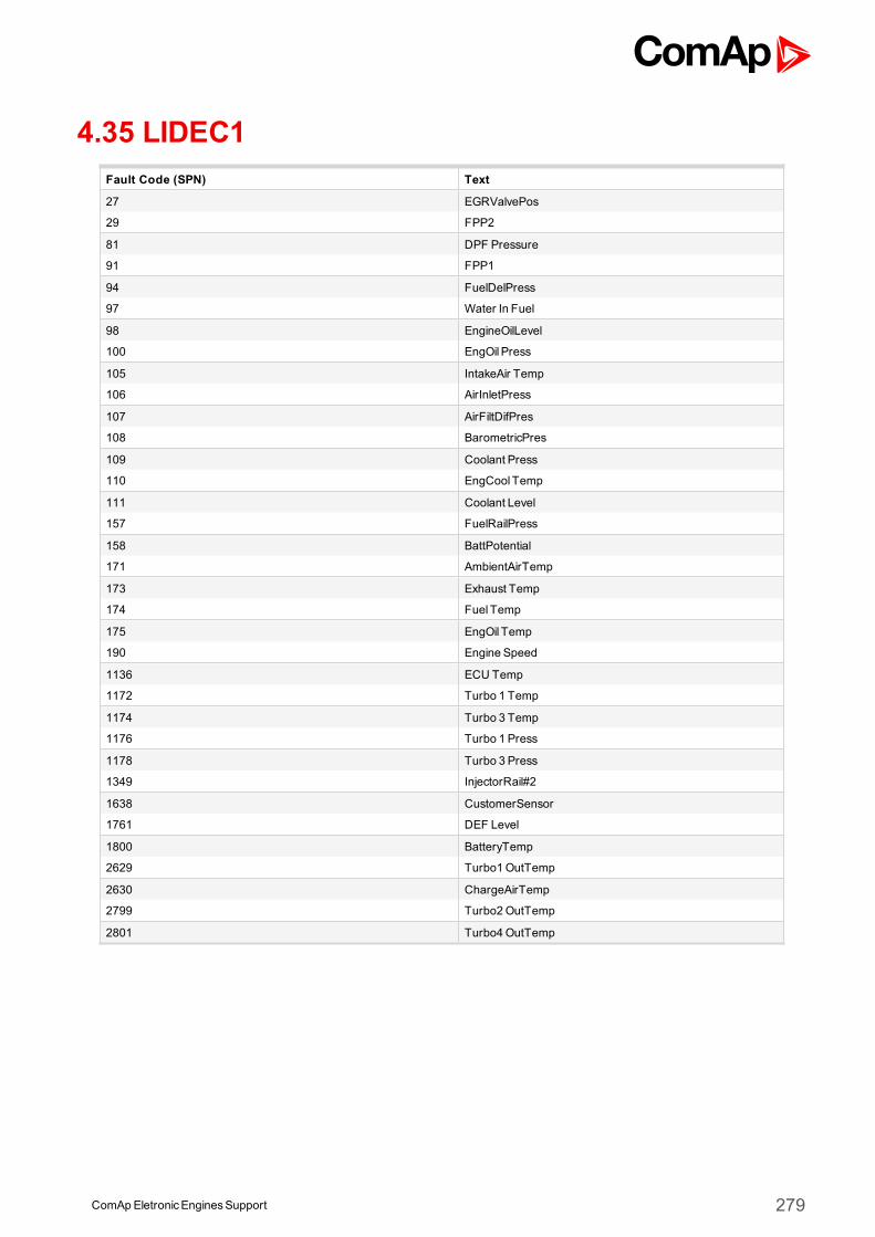
ComApEletronicEnginesSupport 279
4.35 LIDEC1Fault Code (SPN) Text
27 EGRValvePos
29 FPP2
81 DPF Pressure
91 FPP1
94 FuelDelPress
97 Water In Fuel
98 EngineOilLevel
100 EngOil Press
105 IntakeAir Temp
106 AirInletPress
107 AirFiltDifPres
108 BarometricPres
109 Coolant Press
110 EngCool Temp
111 Coolant Level
157 FuelRailPress
158 BattPotential
171 AmbientAirTemp
173 Exhaust Temp
174 Fuel Temp
175 EngOil Temp
190 Engine Speed
1136 ECU Temp
1172 Turbo 1 Temp
1174 Turbo 3 Temp
1176 Turbo 1 Press
1178 Turbo 3 Press
1349 InjectorRail#2
1638 CustomerSensor
1761 DEF Level
1800 BatteryTemp
2629 Turbo1OutTemp
2630 ChargeAirTemp
2799 Turbo2OutTemp
2801 Turbo4OutTemp
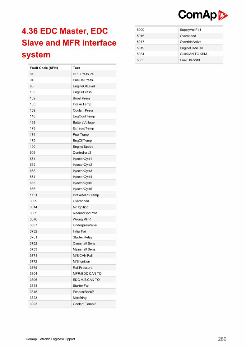
4.36 EDC Master, EDCSlave and MFR interfacesystem
Fault Code (SPN) Text
81 DPF Pressure
94 FuelDelPress
98 EngineOilLevel
100 EngOil Press
102 Boost Press
105 Intake Temp
109 Coolant Press
110 EngCool Temp
168 BatteryVoltage
173 Exhaust Temp
174 Fuel Temp
175 EngOil Temp
190 Engine Speed
609 Controller#2
651 InjectorCyl#1
652 InjectorCyl#2
653 InjectorCyl#3
654 InjectorCyl#4
655 InjectorCyl#5
656 InjectorCyl#6
1131 IntakeMan2Temp
3009 Overspped
3014 No Ignition
3069 RedundSpdProt
3076 WrongMFR
3687 UnderpresValve
3732 Initial Fail
3751 Starter Relay
3752 Camshaft Sens
3753 Mainshaft Sens
3771 M/SCAN Fail
3772 M/S Ignition
3775 Rail Pressure
3804 MFR/EDC CAN TO
3806 EDCM/SCAN TO
3813 Starter Fail
3815 ExhaustBackP
3823 Missfiring
3923 Coolant Temp 2
5000 SupplyVoltFail
5016 Overspeed
5017 OverrideActive
5019 EngineCANFail
5034 CustCAN TOKSM
5035 FuelFilterWtrL
ComApEletronicEnginesSupport 280
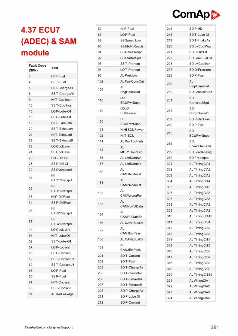
4.37 ECU7(ADEC) & SAMmodule
Fault Code(SPN)
Text
3 HI T-Fuel
4 SST-Fuel
5 HI T-ChargeAir
6 SST-ChargeAir
9 HI T-CoolInter
10 SST-CoolInter
15 LOP-LubeOil
16 SSP-LubeOil
19 HI T-ExhaustA
20 SST-ExhaustA
21 HI T-ExhaustB
22 SST-ExhaustB
23 LOCoolLevel
24 SSCoolLevel
25 HI P-Diff Oil
26 SSP-Diff Oil
30 SSOverspeed
31HIETC1Overspd
32SSETC1Overspd
33 HI P-DiffFuel
34 SSP-DiffFuel
36HIETC2Overspd
37SSETC2Overspd
44 LOCoolLvlInt
51 HI T-LubeOil
52 SST-LubeOil
57 LOP-coolant
58 SSP-Coolant
59 SST-CoolantL3
60 SST-CoolantL4
65 LOP-Fuel
66 SSP-Fuel
67 HI T-Coolant
68 SST-Coolant
81 ALRailLeakage
82 HI P-Fuel
83 LOP-Fuel
89 SSSpeed Low
90 SS IdleNtReach
91 SSReleaseSpd
92 SSStarterSpd
93 SST-Preheat
94 LOT-Preheat
95 AL Prelubric
102 AL FuelConsCnt
104ALEngHoursCnt
118LOECUPwrSupp
119LOLOECUPower
120HIECUPwrSupp
121 HIHI ECUPower
122 HI T-ECU
141 AL PwrTooHigh
142ALMCR1HourExc
176 AL LifeDataNA
177 AL LifeDataInc
180ALCAN1NodeLst
181ALCAN2NodeLst
182ALCANWrongPar
183ALCANNoPUData
184ALCANPUDataEr
186 ALCAN1BusOff
187ALCAN1ErrPass
188 ALCAN2BusOff
189ALCAN2ErrPass
201 SD T-Coolant
202 SD T-Fuel
203 SD T-ChargeAir
205 SD T-CoolInter
206 SD T-ExhaustA
207 SD T-ExhaustB
208 SD P-ChargeAir
211 SD P-LubeOil
212 SD P-Coolant
215 SD P-HD
216 SD T-LubeOil
219 SD T-IntakeAir
220 SD LvlCoolWatr
221 SD P-Diff Oil
222 SD LeakFuelLvl
223 SD LvlCoolIntr
227 SDOilPressure
228 SD P-Fuel
229ALStopCamshaf
230 SD CranksftSpd
231SDCamshaftSpd
232SDChrgrSpeed1
239 SD P-Diff Fuel
240 SD P-Fuel
245SDECUPwrSupp
266SDSpeedDemand
269 SD LoadAnalog
270 SD FreqInput
301 AL TimingClA1
302 AL TimingClA2
303 AL TimingClA3
304 AL TimingClA4
305 AL TimingClA5
306 AL TimingClA6
307 AL TimingClA7
308 AL TimingClA8
309 AL TimingClA9
310 AL TimingClA10
311 AL TimingClB1
312 AL TimingClB2
313 AL TimingClB3
314 AL TimingClB4
315 AL TimingClB5
316 AL TimingClB6
317 AL TimingClB7
318 AL TimingClB8
319 AL TimingClB9
320 AL TimingClB10
321 ALWiringClA1
322 ALWiringClA2
323 ALWiringClA3
324 ALWiringClA4
ComApEletronicEnginesSupport 281
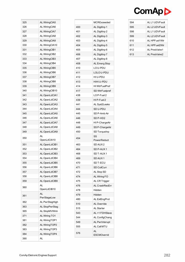
325 ALWiringClA5
326 ALWiringClA6
327 ALWiringClA7
328 ALWiringClA8
329 ALWiringClA9
330 ALWiringClA10
331 ALWiringClB1
332 ALWiringClB2
333 ALWiringClB3
334 ALWiringClB4
335 ALWiringClB5
336 ALWiringClB6
337 ALWiringClB7
338 ALWiringClB8
339 ALWiringClB9
340 ALWiringClB10
341 ALOpenLdClA1
342 ALOpenLdClA2
343 ALOpenLdClA3
344 ALOpenLdClA4
345 ALOpenLdClA5
346 ALOpenLdClA6
347 ALOpenLdClA7
348 ALOpenLdClA8
349 ALOpenLdClA9
350ALOpenLdClA10
351 ALOpenLdClB1
352 ALOpenLdClB2
353 ALOpenLdClB3
354 ALOpenLdClB4
355 ALOpenLdClB5
356 ALOpenLdClB6
357 ALOpenLdClB7
358 ALOpenLdClB8
359 ALOpenLdClB9
360ALOpenLdClB10
361ALPwrStageLow
362 AL PwrStagHigh
363 AL StopPwrStag
365 AL StopMVWirin
371 ALWiring TO1
381 ALWiringTOP1
382 ALWiringTOP2
383 ALWiringTOP3
384 ALWiringTOP4
390 AL
MCRExceeded
400 ALDigitInp 1
401 ALDigitInp 2
402 ALDigitInp 3
403 ALDigitInp 4
404 ALDigitInp 5
405 ALDigitInp 6
406 ALDigitInp 7
407 ALDigitInp 8
408 AL Emerg Stop
410 LOU-PDU
411 LOLOU-PDU
412 HI U-PDU
413 HIHI U-PDU
414 HIWtrFuelPref
417 SDWtrFuelpref
438 LOP-Fuel 2
439 HI P-Fuel 2
441 AL Syst2Leaks
444 SD U-PDU
445 SD P-AmbAir
446 SD P-HD2
448 HI P-ChargeAir
449 SSP-ChargeAir
450 SD TorqueInp
454SSPowerReduct
463 SD AUX2
464 SD P-AUX1
468 SD T-AUX1
469 SD AUX1
470 SD T-ECU
471 SD CoilCurr
472 AL Stop SD
474 ALWiring FO
475 ALCR Trigger
476 ALCrashRecErr
478 Hidden
479 Hidden
480 AL ExtEngProt
510 ALOverride
515 AL Starter
543 AL >1 FDHSlave
544 ALConfigChang
549 AL PwrInterupt
555 ALCallMTU
576ALESCMOverrid
594 AL L1 UDVFault
595 AL L2 UDVFault
598 AL L1 UDVFault
599 AL L2 UDVFault
610 ALHPFuel1Wir
611 ALHPFuel2Wir
612 AL PresValve1
613 AL PresValve2
ComApEletronicEnginesSupport 282
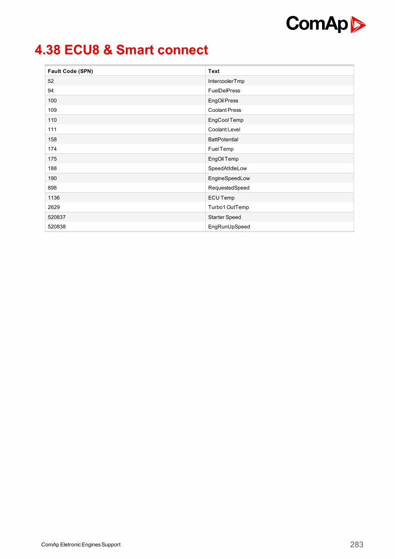
ComApEletronicEnginesSupport 283
4.38 ECU8 & Smart connectFault Code (SPN) Text
52 IntercoolerTmp
94 FuelDelPress
100 EngOil Press
109 Coolant Press
110 EngCool Temp
111 Coolant Level
158 BattPotential
174 Fuel Temp
175 EngOil Temp
188 SpeedAtIdleLow
190 EngineSpeedLow
898 RequestedSpeed
1136 ECU Temp
2629 Turbo1OutTemp
520837 Starter Speed
520838 EngRunUpSpeed
ComApEletronicEnginesSupport 284
4.39 DDEC 10
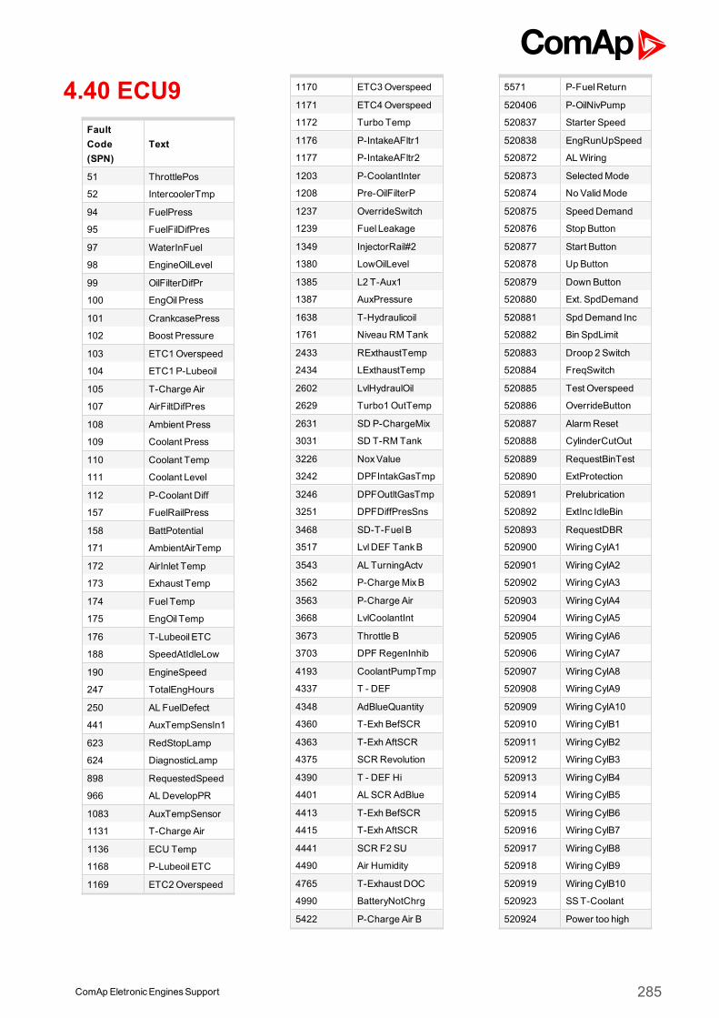
4.40 ECU9FaultCode(SPN)
Text
51 ThrottlePos
52 IntercoolerTmp
94 FuelPress
95 FuelFilDifPres
97 WaterInFuel
98 EngineOilLevel
99 OilFilterDifPr
100 EngOil Press
101 CrankcasePress
102 Boost Pressure
103 ETC1Overspeed
104 ETC1 P-Lubeoil
105 T-Charge Air
107 AirFiltDifPres
108 Ambient Press
109 Coolant Press
110 Coolant Temp
111 Coolant Level
112 P-Coolant Diff
157 FuelRailPress
158 BattPotential
171 AmbientAirTemp
172 AirInlet Temp
173 Exhaust Temp
174 Fuel Temp
175 EngOil Temp
176 T-Lubeoil ETC
188 SpeedAtIdleLow
190 EngineSpeed
247 TotalEngHours
250 AL FuelDefect
441 AuxTempSensIn1
623 RedStopLamp
624 DiagnosticLamp
898 RequestedSpeed
966 ALDevelopPR
1083 AuxTempSensor
1131 T-Charge Air
1136 ECU Temp
1168 P-Lubeoil ETC
1169 ETC2Overspeed
1170 ETC3Overspeed
1171 ETC4Overspeed
1172 Turbo Temp
1176 P-IntakeAFltr1
1177 P-IntakeAFltr2
1203 P-CoolantInter
1208 Pre-OilFilterP
1237 OverrideSwitch
1239 Fuel Leakage
1349 InjectorRail#2
1380 LowOilLevel
1385 L2 T-Aux1
1387 AuxPressure
1638 T-Hydraulicoil
1761 Niveau RMTank
2433 RExthaustTemp
2434 LExthaustTemp
2602 LvlHydraulOil
2629 Turbo1OutTemp
2631 SD P-ChargeMix
3031 SD T-RMTank
3226 NoxValue
3242 DPFIntakGasTmp
3246 DPFOutltGasTmp
3251 DPFDiffPresSns
3468 SD-T-FuelB
3517 LvlDEF TankB
3543 AL TurningActv
3562 P-ChargeMixB
3563 P-Charge Air
3668 LvlCoolantInt
3673 Throttle B
3703 DPF RegenInhib
4193 CoolantPumpTmp
4337 T - DEF
4348 AdBlueQuantity
4360 T-Exh BefSCR
4363 T-Exh AftSCR
4375 SCR Revolution
4390 T - DEF Hi
4401 AL SCR AdBlue
4413 T-Exh BefSCR
4415 T-Exh AftSCR
4441 SCR F2 SU
4490 Air Humidity
4765 T-Exhaust DOC
4990 BatteryNotChrg
5422 P-Charge Air B
5571 P-FuelReturn
520406 P-OilNivPump
520837 Starter Speed
520838 EngRunUpSpeed
520872 ALWiring
520873 SelectedMode
520874 No Valid Mode
520875 Speed Demand
520876 Stop Button
520877 Start Button
520878 Up Button
520879 Down Button
520880 Ext. SpdDemand
520881 SpdDemand Inc
520882 Bin SpdLimit
520883 Droop 2 Switch
520884 FreqSwitch
520885 Test Overspeed
520886 OverrideButton
520887 AlarmReset
520888 CylinderCutOut
520889 RequestBinTest
520890 ExtProtection
520891 Prelubrication
520892 ExtInc IdleBin
520893 RequestDBR
520900 Wiring CylA1
520901 Wiring CylA2
520902 Wiring CylA3
520903 Wiring CylA4
520904 Wiring CylA5
520905 Wiring CylA6
520906 Wiring CylA7
520907 Wiring CylA8
520908 Wiring CylA9
520909 Wiring CylA10
520910 Wiring CylB1
520911 Wiring CylB2
520912 Wiring CylB3
520913 Wiring CylB4
520914 Wiring CylB5
520915 Wiring CylB6
520916 Wiring CylB7
520917 Wiring CylB8
520918 Wiring CylB9
520919 Wiring CylB10
520923 SST-Coolant
520924 Power too high
ComApEletronicEnginesSupport 285
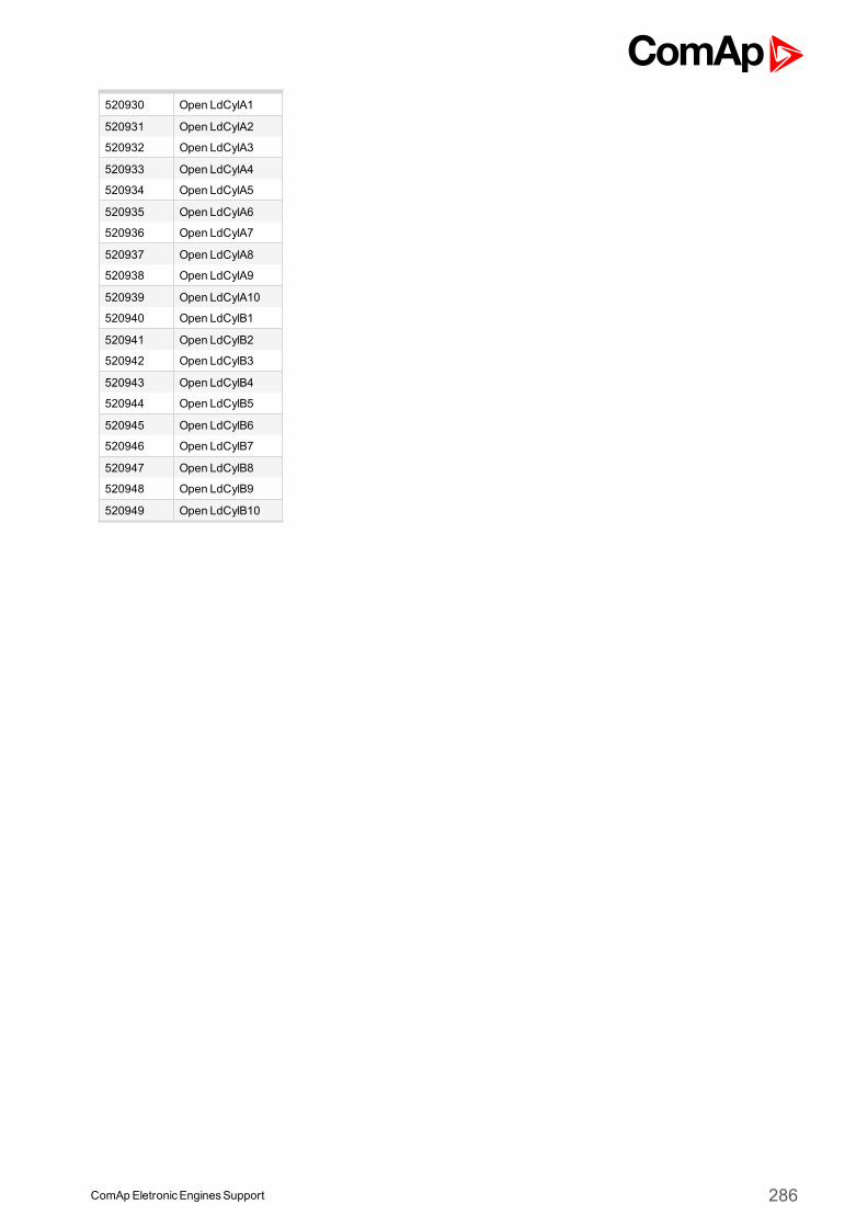
520930 Open LdCylA1
520931 Open LdCylA2
520932 Open LdCylA3
520933 Open LdCylA4
520934 Open LdCylA5
520935 Open LdCylA6
520936 Open LdCylA7
520937 Open LdCylA8
520938 Open LdCylA9
520939 Open LdCylA10
520940 Open LdCylB1
520941 Open LdCylB2
520942 Open LdCylB3
520943 Open LdCylB4
520944 Open LdCylB5
520945 Open LdCylB6
520946 Open LdCylB7
520947 Open LdCylB8
520948 Open LdCylB9
520949 Open LdCylB10
ComApEletronicEnginesSupport 286
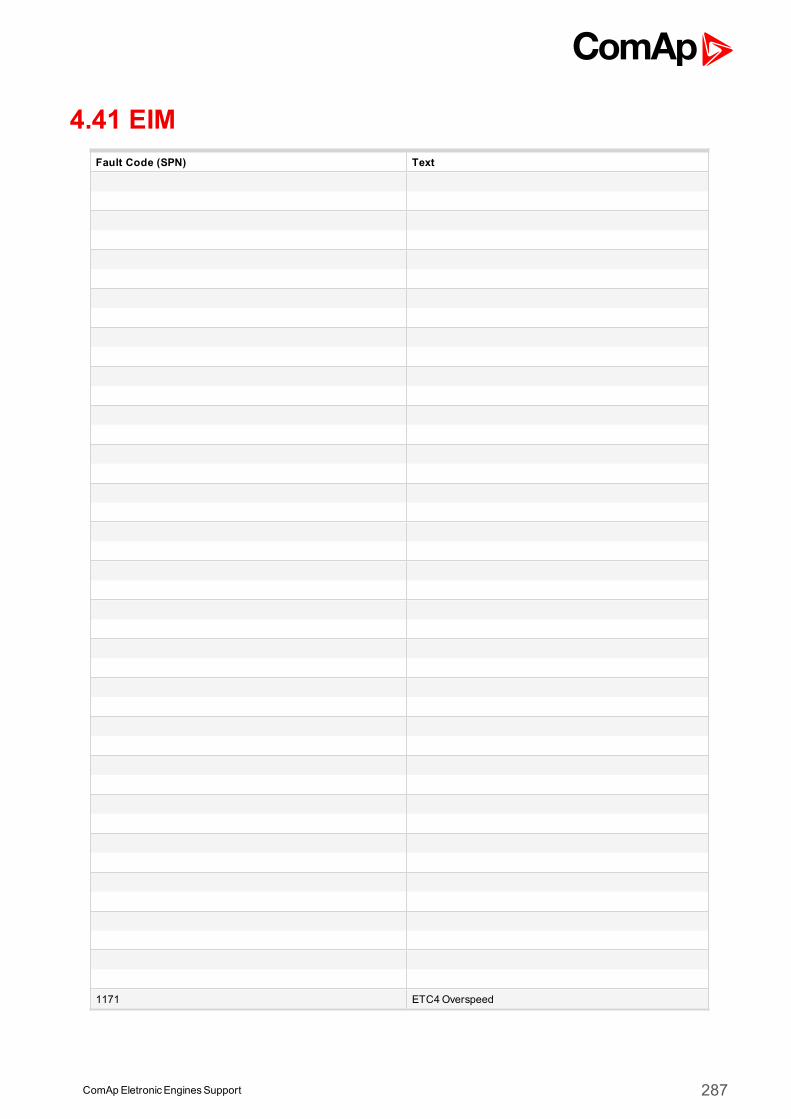
ComApEletronicEnginesSupport 287
4.41 EIMFault Code (SPN) Text
1171 ETC4Overspeed
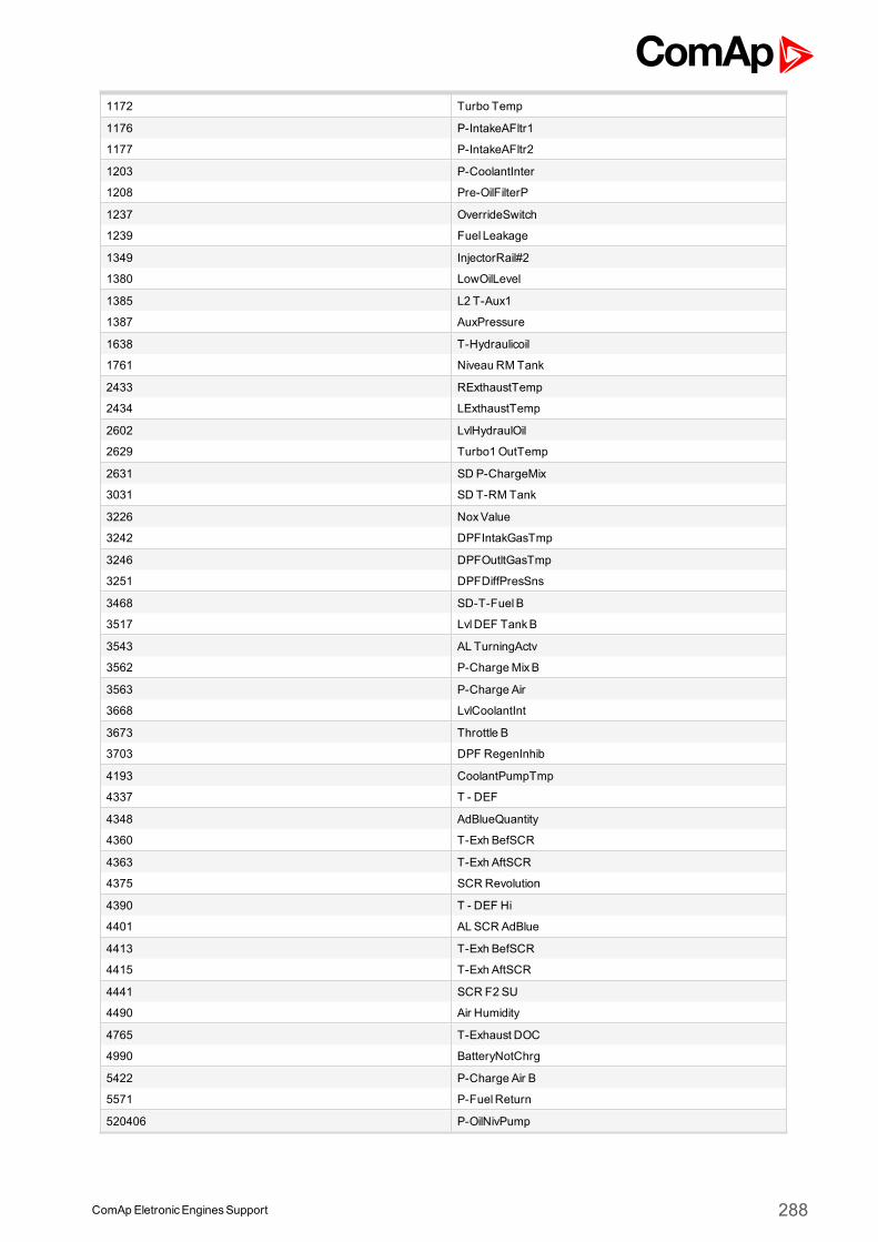
ComApEletronicEnginesSupport 288
1172 Turbo Temp
1176 P-IntakeAFltr1
1177 P-IntakeAFltr2
1203 P-CoolantInter
1208 Pre-OilFilterP
1237 OverrideSwitch
1239 Fuel Leakage
1349 InjectorRail#2
1380 LowOilLevel
1385 L2 T-Aux1
1387 AuxPressure
1638 T-Hydraulicoil
1761 Niveau RMTank
2433 RExthaustTemp
2434 LExthaustTemp
2602 LvlHydraulOil
2629 Turbo1OutTemp
2631 SD P-ChargeMix
3031 SD T-RMTank
3226 NoxValue
3242 DPFIntakGasTmp
3246 DPFOutltGasTmp
3251 DPFDiffPresSns
3468 SD-T-FuelB
3517 LvlDEF TankB
3543 AL TurningActv
3562 P-ChargeMixB
3563 P-Charge Air
3668 LvlCoolantInt
3673 Throttle B
3703 DPF RegenInhib
4193 CoolantPumpTmp
4337 T - DEF
4348 AdBlueQuantity
4360 T-Exh BefSCR
4363 T-Exh AftSCR
4375 SCR Revolution
4390 T - DEF Hi
4401 AL SCR AdBlue
4413 T-Exh BefSCR
4415 T-Exh AftSCR
4441 SCR F2 SU
4490 Air Humidity
4765 T-Exhaust DOC
4990 BatteryNotChrg
5422 P-Charge Air B
5571 P-FuelReturn
520406 P-OilNivPump
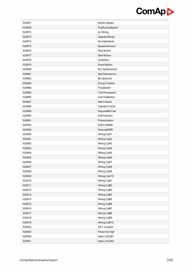
ComApEletronicEnginesSupport 289
520837 Starter Speed
520838 EngRunUpSpeed
520872 ALWiring
520873 SelectedMode
520874 No Valid Mode
520875 Speed Demand
520876 Stop Button
520877 Start Button
520878 Up Button
520879 Down Button
520880 Ext. SpdDemand
520881 SpdDemand Inc
520882 Bin SpdLimit
520883 Droop 2 Switch
520884 FreqSwitch
520885 Test Overspeed
520886 OverrideButton
520887 AlarmReset
520888 CylinderCutOut
520889 RequestBinTest
520890 ExtProtection
520891 Prelubrication
520892 ExtInc IdleBin
520893 RequestDBR
520900 Wiring CylA1
520901 Wiring CylA2
520902 Wiring CylA3
520903 Wiring CylA4
520904 Wiring CylA5
520905 Wiring CylA6
520906 Wiring CylA7
520907 Wiring CylA8
520908 Wiring CylA9
520909 Wiring CylA10
520910 Wiring CylB1
520911 Wiring CylB2
520912 Wiring CylB3
520913 Wiring CylB4
520914 Wiring CylB5
520915 Wiring CylB6
520916 Wiring CylB7
520917 Wiring CylB8
520918 Wiring CylB9
520919 Wiring CylB10
520923 SST-Coolant
520924 Power too high
520930 Open LdCylA1
520931 Open LdCylA2
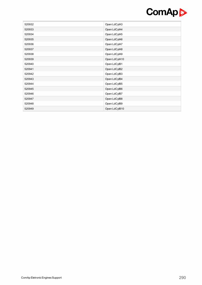
ComApEletronicEnginesSupport 290
520932 Open LdCylA3
520933 Open LdCylA4
520934 Open LdCylA5
520935 Open LdCylA6
520936 Open LdCylA7
520937 Open LdCylA8
520938 Open LdCylA9
520939 Open LdCylA10
520940 Open LdCylB1
520941 Open LdCylB2
520942 Open LdCylB3
520943 Open LdCylB4
520944 Open LdCylB5
520945 Open LdCylB6
520946 Open LdCylB7
520947 Open LdCylB8
520948 Open LdCylB9
520949 Open LdCylB10
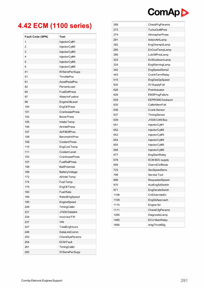
4.42 ECM (1100 series)Fault Code (SPN) Text
1 InjectorCyl#1
2 InjectorCyl#2
3 InjectorCyl#3
4 InjectorCyl#4
5 InjectorCyl#5
6 InjectorCyl#6
41 8VSensPwrSupp
51 ThrottlePos
91 AccelPedalPos
92 PercentLoad
94 FuelDelPress
97 WaterInFuelInd
98 EngineOilLevel
100 EngOil Press
101 CrankcasePress
102 Boost Press
105 Intake Temp
106 AirInletPress
107 AirFiltDifPres
108 BarometricPres
109 Coolant Press
110 EngCool Temp
111 Coolant Level
153 CrankcasePress
157 FuelRailPress
158 BattPotential
168 BatteryVoltage
172 AirInlet Temp
174 Fuel Temp
175 EngOil Temp
183 FuelRate
189 RatedEngSpeed
190 EngineSpeed
228 TimingCalibr
231 J1939 Datalink
234 Incorrect FW
237 VIN
247 TotalEngHours
248 DataLinkComm
253 CheckSysParams
254 ECMFault
261 TimingCalibr
262 5VSensPwrSupp
268 CheckPrgParams
273 TurboOutltPres
274 AtmospherPress
281 ActionAlrtLamp
282 EngOverspdLamp
285 EnCoolTempLamp
286 LubOilPresLamp
323 EnShutdownLamp
324 EngWarningLamp
342 EngSpeedSens2
443 CrankTermRelay
515 EngDesOpSpeed
620 5VSupplyFail
626 PrehActuator
628 EMSProgFailure
629 EEPROMChecksum
630 CalibrMemFail
636 CrankSensor
637 TimingSensor
639 J1939 CAN Bus
651 InjectorCyl#1
652 InjectorCyl#2
653 InjectorCyl#3
654 InjectorCyl#4
655 InjectorCyl#5
656 InjectorCyl#6
677 EngStartRelay
678 ECM 8DC supply
695 OverrdCtrlMode
723 SecSpeedSens
799 Service Tool
898 RequestedSpeed
970 AuxEngSdSwitch
971 EngDerateSwtch
1108 CritOverrideEn
1109 EngSdApproach
1110 Engine Sd
1111 CheckCfgParams
1266 DiagnosticLamp
1485 ECUMainRelay
1690 AnlgThrottlSig
ComApEletronicEnginesSupport 291
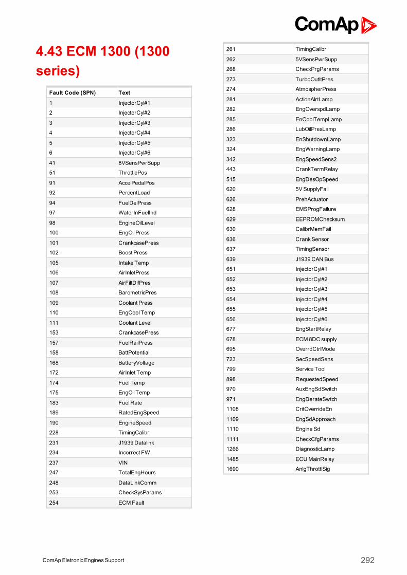
4.43 ECM 1300 (1300series)
Fault Code (SPN) Text
1 InjectorCyl#1
2 InjectorCyl#2
3 InjectorCyl#3
4 InjectorCyl#4
5 InjectorCyl#5
6 InjectorCyl#6
41 8VSensPwrSupp
51 ThrottlePos
91 AccelPedalPos
92 PercentLoad
94 FuelDelPress
97 WaterInFuelInd
98 EngineOilLevel
100 EngOil Press
101 CrankcasePress
102 Boost Press
105 Intake Temp
106 AirInletPress
107 AirFiltDifPres
108 BarometricPres
109 Coolant Press
110 EngCool Temp
111 Coolant Level
153 CrankcasePress
157 FuelRailPress
158 BattPotential
168 BatteryVoltage
172 AirInlet Temp
174 Fuel Temp
175 EngOil Temp
183 FuelRate
189 RatedEngSpeed
190 EngineSpeed
228 TimingCalibr
231 J1939 Datalink
234 Incorrect FW
237 VIN
247 TotalEngHours
248 DataLinkComm
253 CheckSysParams
254 ECMFault
261 TimingCalibr
262 5VSensPwrSupp
268 CheckPrgParams
273 TurboOutltPres
274 AtmospherPress
281 ActionAlrtLamp
282 EngOverspdLamp
285 EnCoolTempLamp
286 LubOilPresLamp
323 EnShutdownLamp
324 EngWarningLamp
342 EngSpeedSens2
443 CrankTermRelay
515 EngDesOpSpeed
620 5VSupplyFail
626 PrehActuator
628 EMSProgFailure
629 EEPROMChecksum
630 CalibrMemFail
636 CrankSensor
637 TimingSensor
639 J1939 CAN Bus
651 InjectorCyl#1
652 InjectorCyl#2
653 InjectorCyl#3
654 InjectorCyl#4
655 InjectorCyl#5
656 InjectorCyl#6
677 EngStartRelay
678 ECM 8DC supply
695 OverrdCtrlMode
723 SecSpeedSens
799 Service Tool
898 RequestedSpeed
970 AuxEngSdSwitch
971 EngDerateSwtch
1108 CritOverrideEn
1109 EngSdApproach
1110 Engine Sd
1111 CheckCfgParams
1266 DiagnosticLamp
1485 ECUMainRelay
1690 AnlgThrottlSig
ComApEletronicEnginesSupport 292
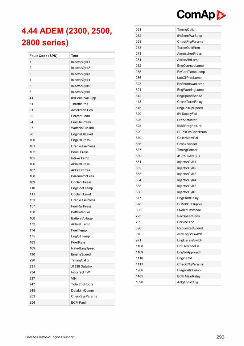
4.44 ADEM (2300, 2500,2800 series)
Fault Code (SPN) Text
1 InjectorCyl#1
2 InjectorCyl#2
3 InjectorCyl#3
4 InjectorCyl#4
5 InjectorCyl#5
6 InjectorCyl#6
41 8VSensPwrSupp
51 ThrottlePos
91 AccelPedalPos
92 PercentLoad
94 FuelDelPress
97 WaterInFuelInd
98 EngineOilLevel
100 EngOil Press
101 CrankcasePress
102 Boost Press
105 Intake Temp
106 AirInletPress
107 AirFiltDifPres
108 BarometricPres
109 Coolant Press
110 EngCool Temp
111 Coolant Level
153 CrankcasePress
157 FuelRailPress
158 BattPotential
168 BatteryVoltage
172 AirInlet Temp
174 Fuel Temp
175 EngOil Temp
183 FuelRate
189 RatedEngSpeed
190 EngineSpeed
228 TimingCalibr
231 J1939 Datalink
234 Incorrect FW
237 VIN
247 TotalEngHours
248 DataLinkComm
253 CheckSysParams
254 ECMFault
261 TimingCalibr
262 5VSensPwrSupp
268 CheckPrgParams
273 TurboOutltPres
274 AtmospherPress
281 ActionAlrtLamp
282 EngOverspdLamp
285 EnCoolTempLamp
286 LubOilPresLamp
323 EnShutdownLamp
324 EngWarningLamp
342 EngSpeedSens2
443 CrankTermRelay
515 EngDesOpSpeed
620 5VSupplyFail
626 PrehActuator
628 EMSProgFailure
629 EEPROMChecksum
630 CalibrMemFail
636 CrankSensor
637 TimingSensor
639 J1939 CAN Bus
651 InjectorCyl#1
652 InjectorCyl#2
653 InjectorCyl#3
654 InjectorCyl#4
655 InjectorCyl#5
656 InjectorCyl#6
677 EngStartRelay
678 ECM 8DC supply
695 OverrdCtrlMode
723 SecSpeedSens
799 Service Tool
898 RequestedSpeed
970 AuxEngSdSwitch
971 EngDerateSwtch
1108 CritOverrideEn
1109 EngSdApproach
1110 Engine Sd
1111 CheckCfgParams
1266 DiagnosticLamp
1485 ECUMainRelay
1690 AnlgThrottlSig
ComApEletronicEnginesSupport 293
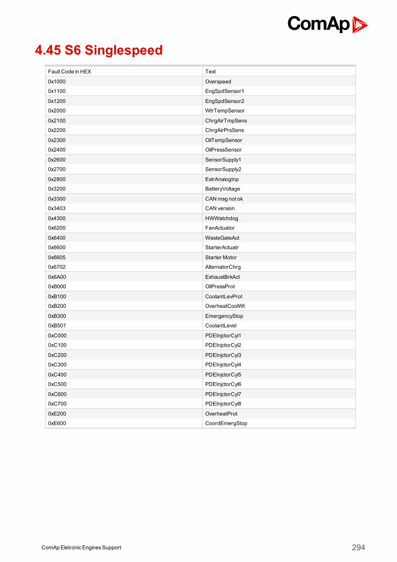
ComApEletronicEnginesSupport 294
4.45 S6 SinglespeedFault Code in HEX Text
0x1000 Overspeed
0x1100 EngSpdSensor1
0x1200 EngSpdSensor2
0x2000 WtrTempSensor
0x2100 ChrgAirTmpSens
0x2200 ChrgAirPrsSens
0x2300 OilTempSensor
0x2400 OilPressSensor
0x2600 SensorSupply1
0x2700 SensorSupply2
0x2800 ExtrAnalogInp
0x3200 BatteryVoltage
0x3300 CANmsg not ok
0x3403 CAN version
0x4300 HWWatchdog
0x6200 FanActuator
0x6400 WasteGateAct
0x6600 StarterActuatr
0x6605 Starter Motor
0x6702 AlternatorChrg
0x6A00 ExhaustBrkAct
0xB000 OilPressProt
0xB100 CoolantLevProt
0xB200 OverheatCoolWt
0xB300 EmergencyStop
0xB501 CoolantLevel
0xC000 PDEInjctorCyl1
0xC100 PDEInjctorCyl2
0xC200 PDEInjctorCyl3
0xC300 PDEInjctorCyl4
0xC400 PDEInjctorCyl5
0xC500 PDEInjctorCyl6
0xC600 PDEInjctorCyl7
0xC700 PDEInjctorCyl8
0xE200 OverheatProt
0xE600 CoordEmergStop
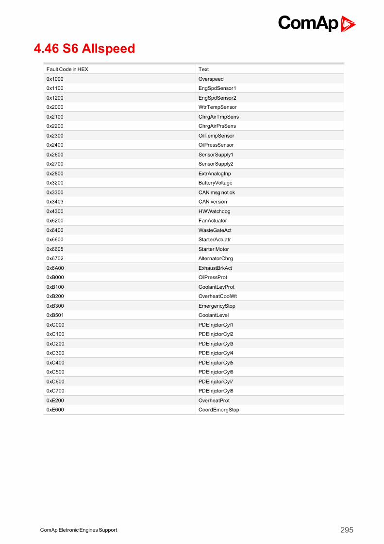
ComApEletronicEnginesSupport 295
4.46 S6 AllspeedFault Code in HEX Text
0x1000 Overspeed
0x1100 EngSpdSensor1
0x1200 EngSpdSensor2
0x2000 WtrTempSensor
0x2100 ChrgAirTmpSens
0x2200 ChrgAirPrsSens
0x2300 OilTempSensor
0x2400 OilPressSensor
0x2600 SensorSupply1
0x2700 SensorSupply2
0x2800 ExtrAnalogInp
0x3200 BatteryVoltage
0x3300 CANmsg not ok
0x3403 CAN version
0x4300 HWWatchdog
0x6200 FanActuator
0x6400 WasteGateAct
0x6600 StarterActuatr
0x6605 Starter Motor
0x6702 AlternatorChrg
0x6A00 ExhaustBrkAct
0xB000 OilPressProt
0xB100 CoolantLevProt
0xB200 OverheatCoolWt
0xB300 EmergencyStop
0xB501 CoolantLevel
0xC000 PDEInjctorCyl1
0xC100 PDEInjctorCyl2
0xC200 PDEInjctorCyl3
0xC300 PDEInjctorCyl4
0xC400 PDEInjctorCyl5
0xC500 PDEInjctorCyl6
0xC600 PDEInjctorCyl7
0xC700 PDEInjctorCyl8
0xE200 OverheatProt
0xE600 CoordEmergStop
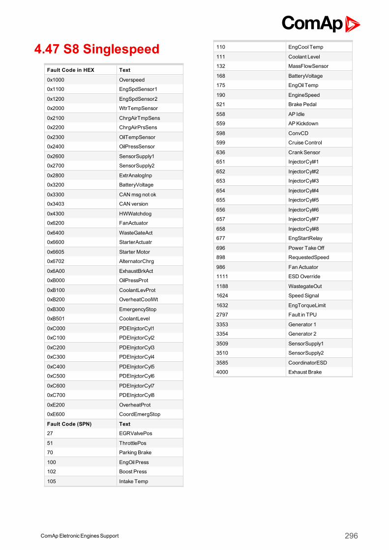
4.47 S8 SinglespeedFault Code in HEX Text
0x1000 Overspeed
0x1100 EngSpdSensor1
0x1200 EngSpdSensor2
0x2000 WtrTempSensor
0x2100 ChrgAirTmpSens
0x2200 ChrgAirPrsSens
0x2300 OilTempSensor
0x2400 OilPressSensor
0x2600 SensorSupply1
0x2700 SensorSupply2
0x2800 ExtrAnalogInp
0x3200 BatteryVoltage
0x3300 CANmsg not ok
0x3403 CAN version
0x4300 HWWatchdog
0x6200 FanActuator
0x6400 WasteGateAct
0x6600 StarterActuatr
0x6605 Starter Motor
0x6702 AlternatorChrg
0x6A00 ExhaustBrkAct
0xB000 OilPressProt
0xB100 CoolantLevProt
0xB200 OverheatCoolWt
0xB300 EmergencyStop
0xB501 CoolantLevel
0xC000 PDEInjctorCyl1
0xC100 PDEInjctorCyl2
0xC200 PDEInjctorCyl3
0xC300 PDEInjctorCyl4
0xC400 PDEInjctorCyl5
0xC500 PDEInjctorCyl6
0xC600 PDEInjctorCyl7
0xC700 PDEInjctorCyl8
0xE200 OverheatProt
0xE600 CoordEmergStop
Fault Code (SPN) Text
27 EGRValvePos
51 ThrottlePos
70 Parking Brake
100 EngOil Press
102 Boost Press
105 Intake Temp
110 EngCool Temp
111 Coolant Level
132 MassFlowSensor
168 BatteryVoltage
175 EngOil Temp
190 EngineSpeed
521 Brake Pedal
558 AP Idle
559 APKickdown
598 ConvCD
599 Cruise Control
636 CrankSensor
651 InjectorCyl#1
652 InjectorCyl#2
653 InjectorCyl#3
654 InjectorCyl#4
655 InjectorCyl#5
656 InjectorCyl#6
657 InjectorCyl#7
658 InjectorCyl#8
677 EngStartRelay
696 Power TakeOff
898 RequestedSpeed
986 Fan Actuator
1111 ESDOverride
1188 WastegateOut
1624 Speed Signal
1632 EngTorqueLimit
2797 Fault in TPU
3353 Generator 1
3354 Generator 2
3509 SensorSupply1
3510 SensorSupply2
3585 CoordinatorESD
4000 Exhaust Brake
ComApEletronicEnginesSupport 296
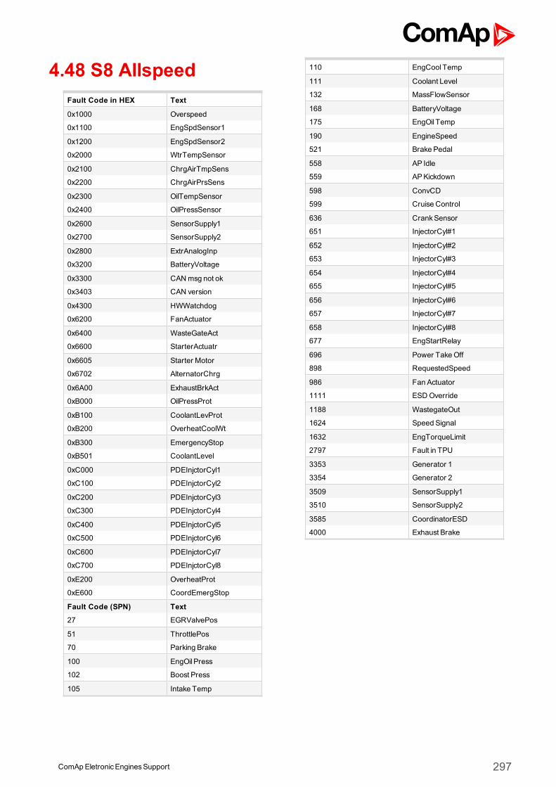
4.48 S8 AllspeedFault Code in HEX Text
0x1000 Overspeed
0x1100 EngSpdSensor1
0x1200 EngSpdSensor2
0x2000 WtrTempSensor
0x2100 ChrgAirTmpSens
0x2200 ChrgAirPrsSens
0x2300 OilTempSensor
0x2400 OilPressSensor
0x2600 SensorSupply1
0x2700 SensorSupply2
0x2800 ExtrAnalogInp
0x3200 BatteryVoltage
0x3300 CANmsg not ok
0x3403 CAN version
0x4300 HWWatchdog
0x6200 FanActuator
0x6400 WasteGateAct
0x6600 StarterActuatr
0x6605 Starter Motor
0x6702 AlternatorChrg
0x6A00 ExhaustBrkAct
0xB000 OilPressProt
0xB100 CoolantLevProt
0xB200 OverheatCoolWt
0xB300 EmergencyStop
0xB501 CoolantLevel
0xC000 PDEInjctorCyl1
0xC100 PDEInjctorCyl2
0xC200 PDEInjctorCyl3
0xC300 PDEInjctorCyl4
0xC400 PDEInjctorCyl5
0xC500 PDEInjctorCyl6
0xC600 PDEInjctorCyl7
0xC700 PDEInjctorCyl8
0xE200 OverheatProt
0xE600 CoordEmergStop
Fault Code (SPN) Text
27 EGRValvePos
51 ThrottlePos
70 Parking Brake
100 EngOil Press
102 Boost Press
105 Intake Temp
110 EngCool Temp
111 Coolant Level
132 MassFlowSensor
168 BatteryVoltage
175 EngOil Temp
190 EngineSpeed
521 Brake Pedal
558 AP Idle
559 APKickdown
598 ConvCD
599 Cruise Control
636 CrankSensor
651 InjectorCyl#1
652 InjectorCyl#2
653 InjectorCyl#3
654 InjectorCyl#4
655 InjectorCyl#5
656 InjectorCyl#6
657 InjectorCyl#7
658 InjectorCyl#8
677 EngStartRelay
696 Power TakeOff
898 RequestedSpeed
986 Fan Actuator
1111 ESDOverride
1188 WastegateOut
1624 Speed Signal
1632 EngTorqueLimit
2797 Fault in TPU
3353 Generator 1
3354 Generator 2
3509 SensorSupply1
3510 SensorSupply2
3585 CoordinatorESD
4000 Exhaust Brake
ComApEletronicEnginesSupport 297
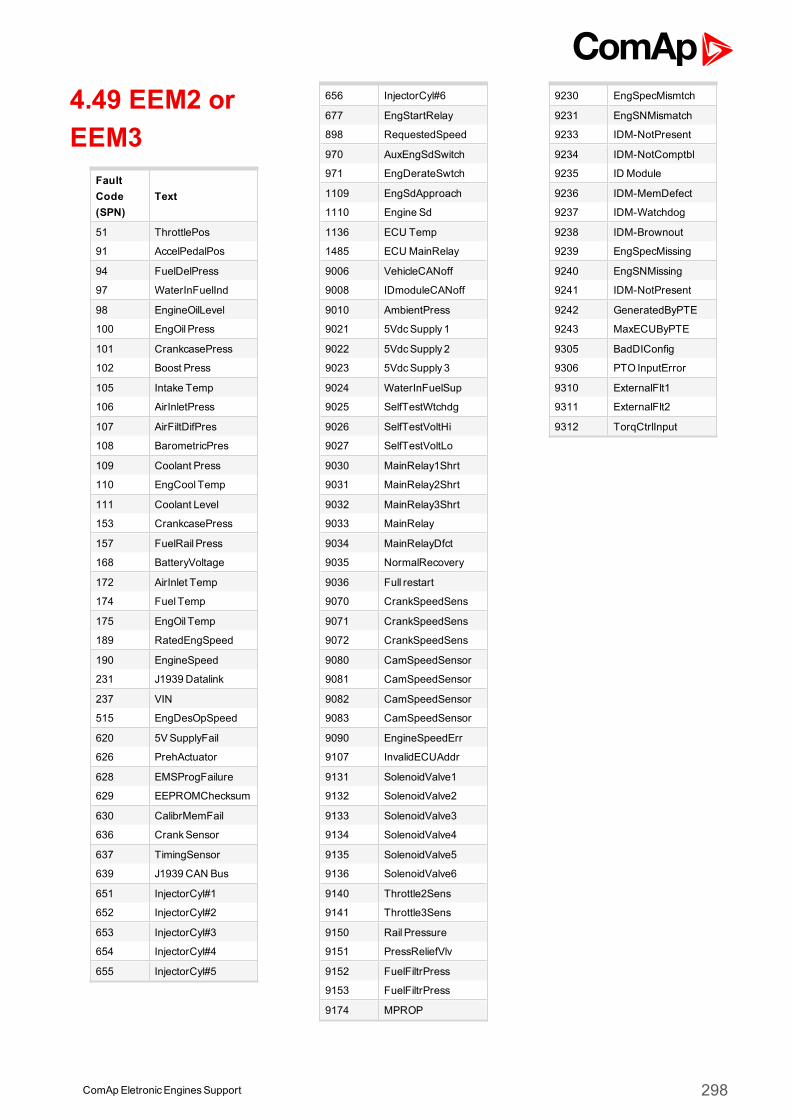
4.49 EEM2 orEEM3
FaultCode(SPN)
Text
51 ThrottlePos
91 AccelPedalPos
94 FuelDelPress
97 WaterInFuelInd
98 EngineOilLevel
100 EngOil Press
101 CrankcasePress
102 Boost Press
105 Intake Temp
106 AirInletPress
107 AirFiltDifPres
108 BarometricPres
109 Coolant Press
110 EngCool Temp
111 Coolant Level
153 CrankcasePress
157 FuelRail Press
168 BatteryVoltage
172 AirInlet Temp
174 Fuel Temp
175 EngOil Temp
189 RatedEngSpeed
190 EngineSpeed
231 J1939 Datalink
237 VIN
515 EngDesOpSpeed
620 5VSupplyFail
626 PrehActuator
628 EMSProgFailure
629 EEPROMChecksum
630 CalibrMemFail
636 CrankSensor
637 TimingSensor
639 J1939 CAN Bus
651 InjectorCyl#1
652 InjectorCyl#2
653 InjectorCyl#3
654 InjectorCyl#4
655 InjectorCyl#5
656 InjectorCyl#6
677 EngStartRelay
898 RequestedSpeed
970 AuxEngSdSwitch
971 EngDerateSwtch
1109 EngSdApproach
1110 Engine Sd
1136 ECU Temp
1485 ECUMainRelay
9006 VehicleCANoff
9008 IDmoduleCANoff
9010 AmbientPress
9021 5VdcSupply 1
9022 5VdcSupply 2
9023 5VdcSupply 3
9024 WaterInFuelSup
9025 SelfTestWtchdg
9026 SelfTestVoltHi
9027 SelfTestVoltLo
9030 MainRelay1Shrt
9031 MainRelay2Shrt
9032 MainRelay3Shrt
9033 MainRelay
9034 MainRelayDfct
9035 NormalRecovery
9036 Full restart
9070 CrankSpeedSens
9071 CrankSpeedSens
9072 CrankSpeedSens
9080 CamSpeedSensor
9081 CamSpeedSensor
9082 CamSpeedSensor
9083 CamSpeedSensor
9090 EngineSpeedErr
9107 InvalidECUAddr
9131 SolenoidValve1
9132 SolenoidValve2
9133 SolenoidValve3
9134 SolenoidValve4
9135 SolenoidValve5
9136 SolenoidValve6
9140 Throttle2Sens
9141 Throttle3Sens
9150 Rail Pressure
9151 PressReliefVlv
9152 FuelFiltrPress
9153 FuelFiltrPress
9174 MPROP
9230 EngSpecMismtch
9231 EngSNMismatch
9233 IDM-NotPresent
9234 IDM-NotComptbl
9235 ID Module
9236 IDM-MemDefect
9237 IDM-Watchdog
9238 IDM-Brownout
9239 EngSpecMissing
9240 EngSNMissing
9241 IDM-NotPresent
9242 GeneratedByPTE
9243 MaxECUByPTE
9305 BadDIConfig
9306 PTO InputError
9310 ExternalFlt1
9311 ExternalFlt2
9312 TorqCtrlInput
ComAp EletronicEnginesSupport 298
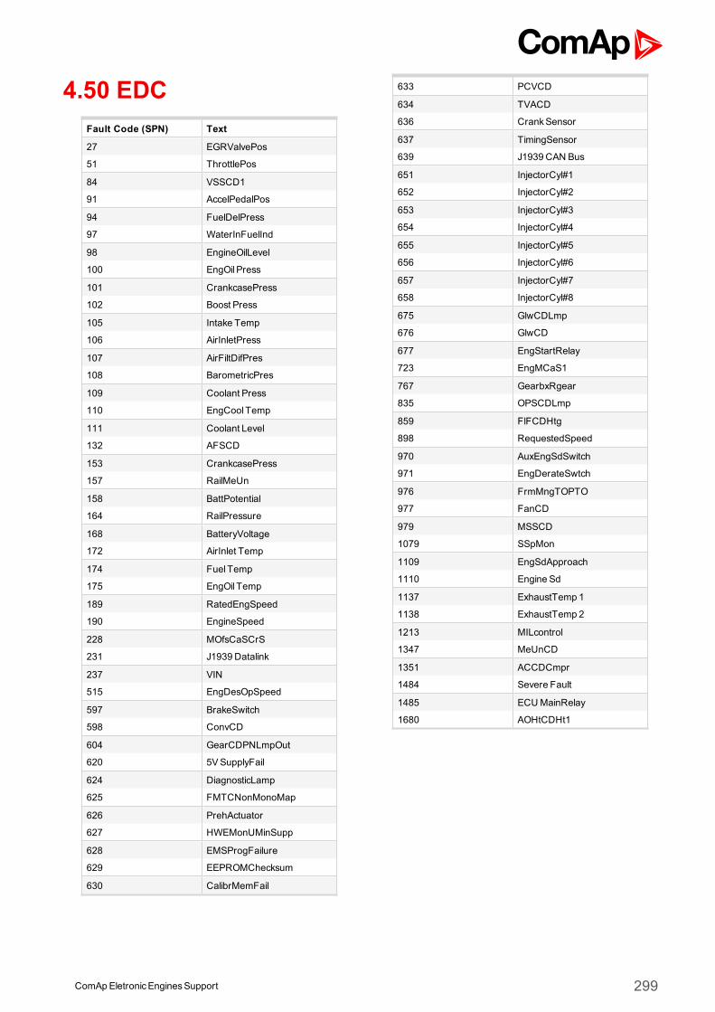
4.50 EDCFault Code (SPN) Text
27 EGRValvePos
51 ThrottlePos
84 VSSCD1
91 AccelPedalPos
94 FuelDelPress
97 WaterInFuelInd
98 EngineOilLevel
100 EngOil Press
101 CrankcasePress
102 Boost Press
105 Intake Temp
106 AirInletPress
107 AirFiltDifPres
108 BarometricPres
109 Coolant Press
110 EngCool Temp
111 Coolant Level
132 AFSCD
153 CrankcasePress
157 RailMeUn
158 BattPotential
164 RailPressure
168 BatteryVoltage
172 AirInlet Temp
174 Fuel Temp
175 EngOil Temp
189 RatedEngSpeed
190 EngineSpeed
228 MOfsCaSCrS
231 J1939 Datalink
237 VIN
515 EngDesOpSpeed
597 BrakeSwitch
598 ConvCD
604 GearCDPNLmpOut
620 5VSupplyFail
624 DiagnosticLamp
625 FMTCNonMonoMap
626 PrehActuator
627 HWEMonUMinSupp
628 EMSProgFailure
629 EEPROMChecksum
630 CalibrMemFail
633 PCVCD
634 TVACD
636 CrankSensor
637 TimingSensor
639 J1939 CAN Bus
651 InjectorCyl#1
652 InjectorCyl#2
653 InjectorCyl#3
654 InjectorCyl#4
655 InjectorCyl#5
656 InjectorCyl#6
657 InjectorCyl#7
658 InjectorCyl#8
675 GlwCDLmp
676 GlwCD
677 EngStartRelay
723 EngMCaS1
767 GearbxRgear
835 OPSCDLmp
859 FlFCDHtg
898 RequestedSpeed
970 AuxEngSdSwitch
971 EngDerateSwtch
976 FrmMngTOPTO
977 FanCD
979 MSSCD
1079 SSpMon
1109 EngSdApproach
1110 Engine Sd
1137 ExhaustTemp 1
1138 ExhaustTemp 2
1213 MILcontrol
1347 MeUnCD
1351 ACCDCmpr
1484 Severe Fault
1485 ECUMainRelay
1680 AOHtCDHt1
ComApEletronicEnginesSupport 299
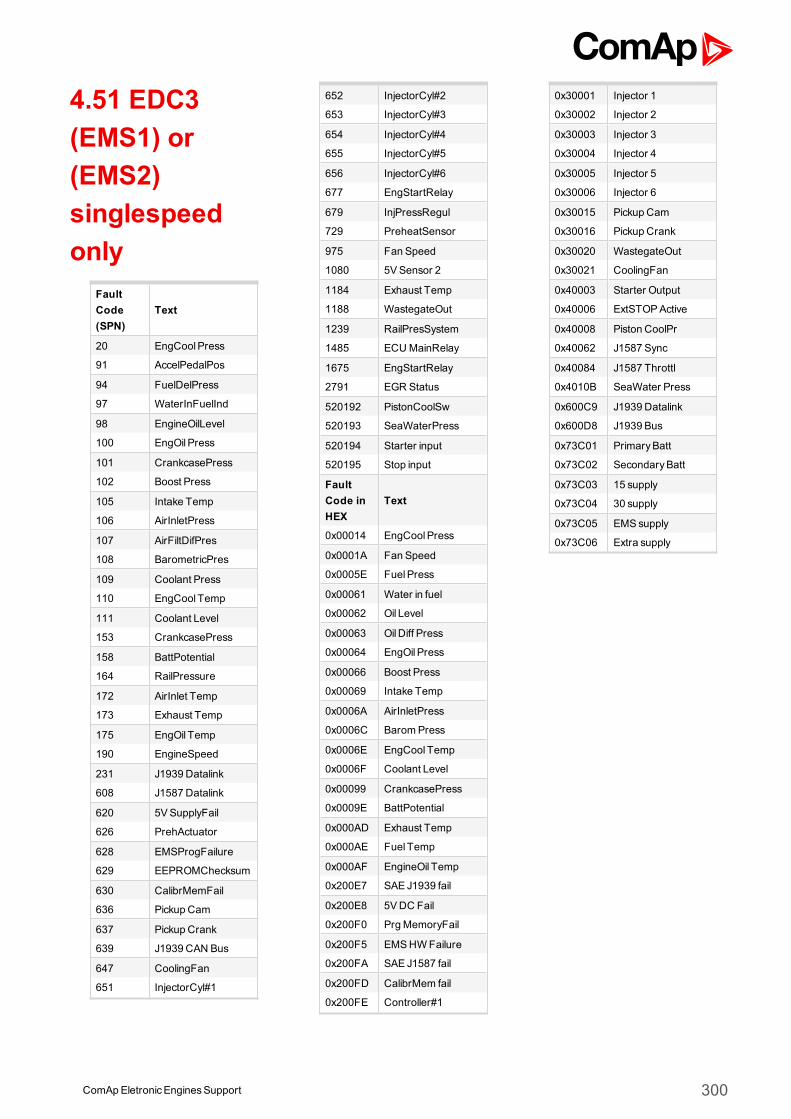
4.51 EDC3(EMS1) or(EMS2)singlespeedonly
FaultCode(SPN)
Text
20 EngCoolPress
91 AccelPedalPos
94 FuelDelPress
97 WaterInFuelInd
98 EngineOilLevel
100 EngOil Press
101 CrankcasePress
102 Boost Press
105 Intake Temp
106 AirInletPress
107 AirFiltDifPres
108 BarometricPres
109 Coolant Press
110 EngCool Temp
111 Coolant Level
153 CrankcasePress
158 BattPotential
164 RailPressure
172 AirInlet Temp
173 Exhaust Temp
175 EngOil Temp
190 EngineSpeed
231 J1939 Datalink
608 J1587 Datalink
620 5VSupplyFail
626 PrehActuator
628 EMSProgFailure
629 EEPROMChecksum
630 CalibrMemFail
636 Pickup Cam
637 Pickup Crank
639 J1939 CAN Bus
647 CoolingFan
651 InjectorCyl#1
652 InjectorCyl#2
653 InjectorCyl#3
654 InjectorCyl#4
655 InjectorCyl#5
656 InjectorCyl#6
677 EngStartRelay
679 InjPressRegul
729 PreheatSensor
975 Fan Speed
1080 5VSensor 2
1184 Exhaust Temp
1188 WastegateOut
1239 RailPresSystem
1485 ECUMainRelay
1675 EngStartRelay
2791 EGR Status
520192 PistonCoolSw
520193 SeaWaterPress
520194 Starter input
520195 Stop input
FaultCode inHEX
Text
0x00014 EngCoolPress
0x0001A Fan Speed
0x0005E FuelPress
0x00061 Water in fuel
0x00062 Oil Level
0x00063 OilDiff Press
0x00064 EngOil Press
0x00066 Boost Press
0x00069 Intake Temp
0x0006A AirInletPress
0x0006C BaromPress
0x0006E EngCool Temp
0x0006F Coolant Level
0x00099 CrankcasePress
0x0009E BattPotential
0x000AD Exhaust Temp
0x000AE Fuel Temp
0x000AF EngineOil Temp
0x200E7 SAE J1939 fail
0x200E8 5VDC Fail
0x200F0 PrgMemoryFail
0x200F5 EMSHWFailure
0x200FA SAE J1587 fail
0x200FD CalibrMem fail
0x200FE Controller#1
0x30001 Injector 1
0x30002 Injector 2
0x30003 Injector 3
0x30004 Injector 4
0x30005 Injector 5
0x30006 Injector 6
0x30015 Pickup Cam
0x30016 Pickup Crank
0x30020 WastegateOut
0x30021 CoolingFan
0x40003 Starter Output
0x40006 ExtSTOPActive
0x40008 Piston CoolPr
0x40062 J1587 Sync
0x40084 J1587 Throttl
0x4010B SeaWater Press
0x600C9 J1939 Datalink
0x600D8 J1939 Bus
0x73C01 PrimaryBatt
0x73C02 SecondaryBatt
0x73C03 15 supply
0x73C04 30 supply
0x73C05 EMSsupply
0x73C06 Extra supply
ComAp EletronicEnginesSupport 300
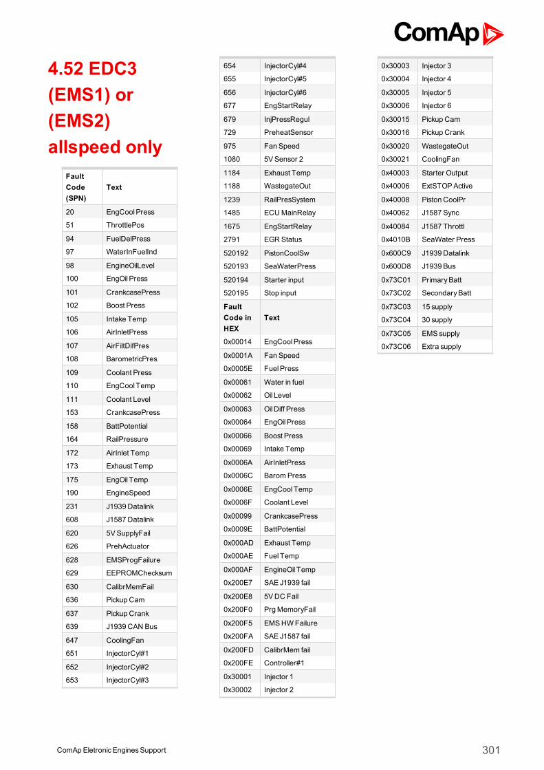
4.52 EDC3(EMS1) or(EMS2)allspeed only
FaultCode(SPN)
Text
20 EngCoolPress
51 ThrottlePos
94 FuelDelPress
97 WaterInFuelInd
98 EngineOilLevel
100 EngOil Press
101 CrankcasePress
102 Boost Press
105 Intake Temp
106 AirInletPress
107 AirFiltDifPres
108 BarometricPres
109 Coolant Press
110 EngCool Temp
111 Coolant Level
153 CrankcasePress
158 BattPotential
164 RailPressure
172 AirInlet Temp
173 Exhaust Temp
175 EngOil Temp
190 EngineSpeed
231 J1939 Datalink
608 J1587 Datalink
620 5VSupplyFail
626 PrehActuator
628 EMSProgFailure
629 EEPROMChecksum
630 CalibrMemFail
636 Pickup Cam
637 Pickup Crank
639 J1939 CAN Bus
647 CoolingFan
651 InjectorCyl#1
652 InjectorCyl#2
653 InjectorCyl#3
654 InjectorCyl#4
655 InjectorCyl#5
656 InjectorCyl#6
677 EngStartRelay
679 InjPressRegul
729 PreheatSensor
975 Fan Speed
1080 5VSensor 2
1184 Exhaust Temp
1188 WastegateOut
1239 RailPresSystem
1485 ECUMainRelay
1675 EngStartRelay
2791 EGR Status
520192 PistonCoolSw
520193 SeaWaterPress
520194 Starter input
520195 Stop input
FaultCode inHEX
Text
0x00014 EngCoolPress
0x0001A Fan Speed
0x0005E FuelPress
0x00061 Water in fuel
0x00062 Oil Level
0x00063 OilDiff Press
0x00064 EngOil Press
0x00066 Boost Press
0x00069 Intake Temp
0x0006A AirInletPress
0x0006C BaromPress
0x0006E EngCool Temp
0x0006F Coolant Level
0x00099 CrankcasePress
0x0009E BattPotential
0x000AD Exhaust Temp
0x000AE Fuel Temp
0x000AF EngineOil Temp
0x200E7 SAE J1939 fail
0x200E8 5VDC Fail
0x200F0 PrgMemoryFail
0x200F5 EMSHWFailure
0x200FA SAE J1587 fail
0x200FD CalibrMem fail
0x200FE Controller#1
0x30001 Injector 1
0x30002 Injector 2
0x30003 Injector 3
0x30004 Injector 4
0x30005 Injector 5
0x30006 Injector 6
0x30015 Pickup Cam
0x30016 Pickup Crank
0x30020 WastegateOut
0x30021 CoolingFan
0x40003 Starter Output
0x40006 ExtSTOPActive
0x40008 Piston CoolPr
0x40062 J1587 Sync
0x40084 J1587 Throttl
0x4010B SeaWater Press
0x600C9 J1939 Datalink
0x600D8 J1939 Bus
0x73C01 PrimaryBatt
0x73C02 SecondaryBatt
0x73C03 15 supply
0x73C04 30 supply
0x73C05 EMSsupply
0x73C06 Extra supply
ComAp EletronicEnginesSupport 301
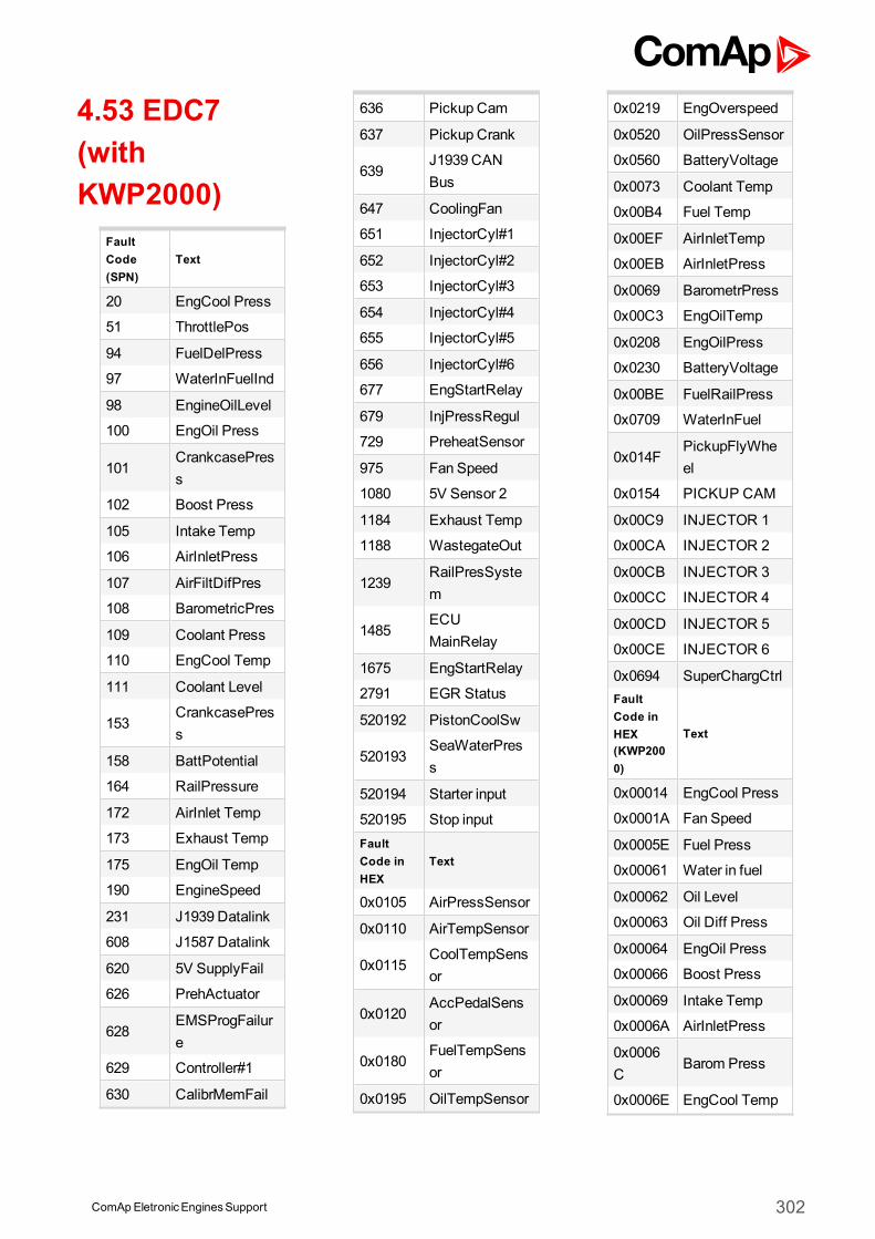
4.53 EDC7(withKWP2000)
FaultCode(SPN)
Text
20 EngCool Press
51 ThrottlePos
94 FuelDelPress
97 WaterInFuelInd
98 EngineOilLevel
100 EngOil Press
101CrankcasePress
102 Boost Press
105 Intake Temp
106 AirInletPress
107 AirFiltDifPres
108 BarometricPres
109 Coolant Press
110 EngCool Temp
111 Coolant Level
153CrankcasePress
158 BattPotential
164 RailPressure
172 AirInlet Temp
173 Exhaust Temp
175 EngOil Temp
190 EngineSpeed
231 J1939 Datalink
608 J1587 Datalink
620 5V SupplyFail
626 PrehActuator
628EMSProgFailure
629 Controller#1
630 CalibrMemFail
636 Pickup Cam
637 Pickup Crank
639J1939 CANBus
647 CoolingFan
651 InjectorCyl#1
652 InjectorCyl#2
653 InjectorCyl#3
654 InjectorCyl#4
655 InjectorCyl#5
656 InjectorCyl#6
677 EngStartRelay
679 InjPressRegul
729 PreheatSensor
975 Fan Speed
1080 5V Sensor 2
1184 Exhaust Temp
1188 WastegateOut
1239RailPresSystem
1485ECUMainRelay
1675 EngStartRelay
2791 EGR Status
520192 PistonCoolSw
520193SeaWaterPress
520194 Starter input
520195 Stop inputFaultCode inHEX
Text
0x0105 AirPressSensor
0x0110 AirTempSensor
0x0115CoolTempSensor
0x0120AccPedalSensor
0x0180FuelTempSensor
0x0195 OilTempSensor
0x0219 EngOverspeed
0x0520 OilPressSensor
0x0560 BatteryVoltage
0x0073 Coolant Temp
0x00B4 Fuel Temp
0x00EF AirInletTemp
0x00EB AirInletPress
0x0069 BarometrPress
0x00C3 EngOilTemp
0x0208 EngOilPress
0x0230 BatteryVoltage
0x00BE FuelRailPress
0x0709 WaterInFuel
0x014FPickupFlyWheel
0x0154 PICKUP CAM
0x00C9 INJECTOR 1
0x00CA INJECTOR 2
0x00CB INJECTOR 3
0x00CC INJECTOR 4
0x00CD INJECTOR 5
0x00CE INJECTOR 6
0x0694 SuperChargCtrlFaultCode inHEX(KWP2000)
Text
0x00014 EngCool Press
0x0001A Fan Speed
0x0005E Fuel Press
0x00061 Water in fuel
0x00062 Oil Level
0x00063 Oil Diff Press
0x00064 EngOil Press
0x00066 Boost Press
0x00069 Intake Temp
0x0006A AirInletPress
0x0006C
Barom Press
0x0006E EngCool Temp
ComApEletronicEnginesSupport 302
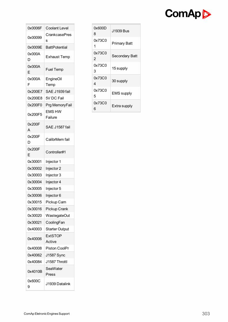
0x0006F Coolant Level
0x00099CrankcasePress
0x0009E BattPotential
0x000AD
Exhaust Temp
0x000AE
Fuel Temp
0x000AF
EngineOilTemp
0x200E7 SAE J1939 fail
0x200E8 5V DC Fail
0x200F0 PrgMemoryFail
0x200F5EMS HWFailure
0x200FA
SAE J1587 fail
0x200FD
CalibrMem fail
0x200FE
Controller#1
0x30001 Injector 1
0x30002 Injector 2
0x30003 Injector 3
0x30004 Injector 4
0x30005 Injector 5
0x30006 Injector 6
0x30015 Pickup Cam
0x30016 Pickup Crank
0x30020 WastegateOut
0x30021 CoolingFan
0x40003 Starter Output
0x40006ExtSTOPActive
0x40008 Piston CoolPr
0x40062 J1587 Sync
0x40084 J1587 Throttl
0x4010BSeaWaterPress
0x600C9
J1939 Datalink
0x600D8
J1939 Bus
0x73C01
Primary Batt
0x73C02
Secondary Batt
0x73C03
15 supply
0x73C04
30 supply
0x73C05
EMS supply
0x73C06
Extra supply
ComApEletronicEnginesSupport 303
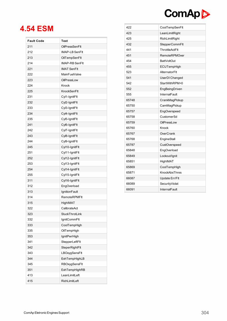
4.54 ESMFault Code Text
211 OilPressSenFlt
212 IMAP-LBSenFlt
213 OilTempSenFlt
214 IMAP-RBSenFlt
221 IMAT SenFlt
222 MainFuelValve
223 OilPressLow
224 Knock
225 KnockSenFlt
231 Cyl1-IgnitFlt
232 Cyl2-IgnitFlt
233 Cyl3-IgnitFlt
234 Cyl4-IgnitFlt
235 Cyl5-IgnitFlt
241 Cyl6-IgnitFlt
242 Cyl7-IgnitFlt
243 Cyl8-IgnitFlt
244 Cyl9-IgnitFlt
245 Cyl10-IgnitFlt
251 Cyl11-IgnitFlt
252 Cyl12-IgnitFlt
253 Cyl13-IgnitFlt
254 Cyl14-IgnitFlt
255 Cyl15-IgnitFlt
311 Cyl16-IgnitFlt
312 EngOverload
313 IgnitionFault
314 RemoteRPMFlt
315 HighIMAT
322 CalibrateAct
323 StuckThrotLink
332 IgnitCommFlt
333 CoolTempHigh
335 OilTempHigh
353 IgnitPwrHigh
341 StepperLeftFlt
342 SteperRightFlt
343 LBOxygSensFlt
344 ExhTempHighLB
345 RBOxygSensFlt
351 ExhTempHighRB
413 LeanLimitLeft
415 RichLimitLeft
422 CoolTempSenFlt
423 LeanLimitRight
425 RichLimitRight
432 StepperCommFlt
441 ThrottleActFlt
451 RemoteRPMOver
454 BattVoltOut
455 ECUTempHigh
523 AlternatorFlt
541 UserDI Changed
542 StartWithRPM>0
552 EngBeingDriven
555 InternalFault
65748 CrankMagPickup
65750 CamMagPickup
65757 EngOverspeed
65758 CustomerSd
65759 OilPressLow
65760 Knock
65767 OverCrank
65768 EngineStall
65787 CustOverspeed
65848 EngOverload
65849 Lockout/Ignit
65851 HighIMAT
65869 CoolTempHigh
65871 KnockAbsThres
66087 Update Err/Flt
66089 SecurityViolat
66091 InternalFault
ComAp EletronicEnginesSupport 304
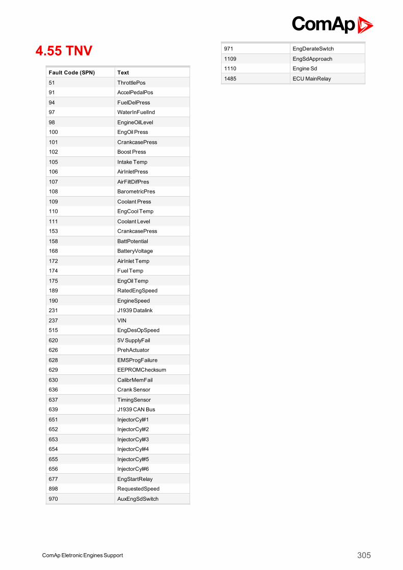
4.55 TNVFault Code (SPN) Text
51 ThrottlePos
91 AccelPedalPos
94 FuelDelPress
97 WaterInFuelInd
98 EngineOilLevel
100 EngOil Press
101 CrankcasePress
102 Boost Press
105 Intake Temp
106 AirInletPress
107 AirFiltDifPres
108 BarometricPres
109 Coolant Press
110 EngCool Temp
111 Coolant Level
153 CrankcasePress
158 BattPotential
168 BatteryVoltage
172 AirInlet Temp
174 Fuel Temp
175 EngOil Temp
189 RatedEngSpeed
190 EngineSpeed
231 J1939 Datalink
237 VIN
515 EngDesOpSpeed
620 5VSupplyFail
626 PrehActuator
628 EMSProgFailure
629 EEPROMChecksum
630 CalibrMemFail
636 CrankSensor
637 TimingSensor
639 J1939 CAN Bus
651 InjectorCyl#1
652 InjectorCyl#2
653 InjectorCyl#3
654 InjectorCyl#4
655 InjectorCyl#5
656 InjectorCyl#6
677 EngStartRelay
898 RequestedSpeed
970 AuxEngSdSwitch
971 EngDerateSwtch
1109 EngSdApproach
1110 Engine Sd
1485 ECUMainRelay
ComApEletronicEnginesSupport 305
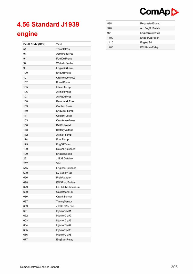
4.56 Standard J1939engine
Fault Code (SPN) Text
51 ThrottlePos
91 AccelPedalPos
94 FuelDelPress
97 WaterInFuelInd
98 EngineOilLevel
100 EngOil Press
101 CrankcasePress
102 Boost Press
105 Intake Temp
106 AirInletPress
107 AirFiltDifPres
108 BarometricPres
109 Coolant Press
110 EngCool Temp
111 Coolant Level
153 CrankcasePress
158 BattPotential
168 BatteryVoltage
172 AirInlet Temp
174 Fuel Temp
175 EngOil Temp
189 RatedEngSpeed
190 EngineSpeed
231 J1939 Datalink
237 VIN
515 EngDesOpSpeed
620 5VSupplyFail
626 PrehActuator
628 EMSProgFailure
629 EEPROMChecksum
630 CalibrMemFail
636 CrankSensor
637 TimingSensor
639 J1939 CAN Bus
651 InjectorCyl#1
652 InjectorCyl#2
653 InjectorCyl#3
654 InjectorCyl#4
655 InjectorCyl#5
656 InjectorCyl#6
677 EngStartRelay
898 RequestedSpeed
970 AuxEngSdSwitch
971 EngDerateSwtch
1109 EngSdApproach
1110 Engine Sd
1485 ECUMainRelay
ComApEletronicEnginesSupport 306
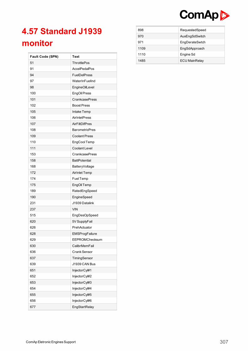
4.57 Standard J1939monitor
Fault Code (SPN) Text
51 ThrottlePos
91 AccelPedalPos
94 FuelDelPress
97 WaterInFuelInd
98 EngineOilLevel
100 EngOil Press
101 CrankcasePress
102 Boost Press
105 Intake Temp
106 AirInletPress
107 AirFiltDifPres
108 BarometricPres
109 Coolant Press
110 EngCool Temp
111 Coolant Level
153 CrankcasePress
158 BattPotential
168 BatteryVoltage
172 AirInlet Temp
174 Fuel Temp
175 EngOil Temp
189 RatedEngSpeed
190 EngineSpeed
231 J1939 Datalink
237 VIN
515 EngDesOpSpeed
620 5VSupplyFail
626 PrehActuator
628 EMSProgFailure
629 EEPROMChecksum
630 CalibrMemFail
636 CrankSensor
637 TimingSensor
639 J1939 CAN Bus
651 InjectorCyl#1
652 InjectorCyl#2
653 InjectorCyl#3
654 InjectorCyl#4
655 InjectorCyl#5
656 InjectorCyl#6
677 EngStartRelay
898 RequestedSpeed
970 AuxEngSdSwitch
971 EngDerateSwtch
1109 EngSdApproach
1110 Engine Sd
1485 ECUMainRelay
ComApEletronicEnginesSupport 307