Embed Size (px)
Citation preview

HILL INTERNATIONAL, INC. AFG/0361/TF 030397EVALUATION OF INVESTMENT OPTIONS FOR THE DEVELOPMENT PROJECT NO. PAG238/R BORHAN/REV.3. OCTOBER 9, 2004OF OIL AND GAS INFRASTRUCTURE IN AFGHANISTAN TASK 4: KABUL-SHEBERGHAN GAS PIPELINE
PAGE 1
TABLE OF CONTENTS
TABLE OF CONTENTS...................................................................................................................................... 1
ANNEXES ............................................................................................................................................................. 4
LIST OF FIGURES AND TABLES.................................................................................................................... 5
ACRONYMS AND ABBREVIATIONS ............................................................................................................. 6
TABLE OF CONVERSION FACTORS............................................................................................................. 9
THE AFGHAN CALENDAR ............................................................................................................................ 10
SOURCES OF INFORMATION....................................................................................................................... 11
1.0 EXECUTIVE SUMMARY .................................................................................................................. 12
1.1 INTRODUCTION ................................................................................................................................... 121.2 THE MAIN ROUTE............................................................................................................................... 141.3 PIPELINE CAPACITY ............................................................................................................................ 151.4 COST ESTIMATE.................................................................................................................................. 171.5 PROJECT SCHEDULE............................................................................................................................ 181.6 GAS PRICING AND TARIFFS................................................................................................................. 18
1.6.1 Proposed Tariff Structure.............................................................................................................. 191.7 KEY FACTORS..................................................................................................................................... 201.8 OTHER RELEVANT PIPELINE STUDIES................................................................................................. 20
2.0 TERMS OF REFERENCE.................................................................................................................. 22
3.0 PIPELINE ROUTING AND CONFIGURATION ............................................................................ 25
3.1 BACKGROUND .................................................................................................................................... 253.1.1 Dependency on Firewood and its Consequences .......................................................................... 26
3.2 OVERVIEW OF THE PROPOSED GAS TRANSMISSION SYSTEM .............................................................. 273.3 DESCRIPTION OF THE PIPELINE ROUTE ............................................................................................... 27
3.3.1 The Primary Route ........................................................................................................................ 293.3.2 Alternate Route A (Km 181 – Km. 297.7)...................................................................................... 303.3.3 Alternate Route B (Km. 336.7 – Km. 387.5).................................................................................. 303.3.4 Alternate Route C ( Km. 420 – Km. 432) ...................................................................................... 31
3.4 PIPELINE DESIGN CRITERIA ................................................................................................................ 313.4.1 Gas Composition and Characteristics .......................................................................................... 313.4.2 Load Factor................................................................................................................................... 323.4.3 Pipeline Capacity .......................................................................................................................... 323.4.4 Gas Reserves ................................................................................................................................. 333.4.5 Operating Pressures...................................................................................................................... 333.4.6 Pipe wall Thickness....................................................................................................................... 333.4.7 Pipe Roughness ............................................................................................................................. 333.4.8 Gas Temperature........................................................................................................................... 343.4.9 Codes and Standards..................................................................................................................... 34
3.5 PIPELINE HYDRAULICS ....................................................................................................................... 343.5.1 Phase I........................................................................................................................................... 373.5.2 Phase-II:........................................................................................................................................ 383.5.3 Phase-III........................................................................................................................................ 39
3.6 GAS COMPRESSION FACILITIES........................................................................................................... 413.7 PIPELINE SUPPORT SYSTEM ................................................................................................................ 41
3.7.1 Control System .............................................................................................................................. 413.7.2 Custody Transfer and Metering .................................................................................................... 423.7.3 Metering System ............................................................................................................................ 423.7.4 Communications and SCADA ...................................................................................................... 43

HILL INTERNATIONAL, INC. AFG/0361/TF 030397EVALUATION OF INVESTMENT OPTIONS FOR THE DEVELOPMENT PROJECT NO. PAG238/R BORHAN/REV.3. OCTOBER 9, 2004OF OIL AND GAS INFRASTRUCTURE IN AFGHANISTAN TASK 4: KABUL-SHEBERGHAN GAS PIPELINE
PAGE 2
3.7.5 Data Monitoring and Control Facility .......................................................................................... 43
4.0 PIPELINE CONSTRUCTION............................................................................................................ 45
4.1 INTRODUCTION ................................................................................................................................... 454.2 TERRAIN DESCRIPTION, SEISMICITY AND FAULT LINES...................................................................... 47
4.2.1 Route Description.......................................................................................................................... 474.2.2 Section I terrain............................................................................................................................. 474.2.2.1 Option 1.................................................................................................................................... 474.2.2.2 Option 2.................................................................................................................................... 484.2.3 Section II terrain ........................................................................................................................... 484.2.3.1 Option 1.................................................................................................................................... 484.2.3.2 Option 2.................................................................................................................................... 484.2.4 Section III terrain .......................................................................................................................... 494.2.5 Seismicity ...................................................................................................................................... 494.2.5.1 Km. 0 – Km. 50: Minor damage probable................................................................................ 494.2.5.2 Km. 50 – Km. 350 Moderate damage probable........................................................................ 494.2.5.3 Km. 350 – Km 508 Major damage probable. ........................................................................... 504.2.6 Fault Lines .................................................................................................................................... 50
4.3 PIPELINE SAFETY FEATURES AND SYSTEMS ....................................................................................... 514.4 SEISMIC PROTECTION, FAULT-LINE CROSSINGS, ROAD AND RIVER CROSSINGS ................................. 52
4.4.1 Seismic Protection......................................................................................................................... 524.4.2 Fault-line Crossings...................................................................................................................... 524.4.3 Road and River Crossings............................................................................................................. 524.4.3.1 Roads........................................................................................................................................ 524.4.3.2 Rivers........................................................................................................................................ 53
4.5 HABITATION AND AGRICULTURE........................................................................................................ 544.6 ACCESS ROADS AND STORAGE SITES. ................................................................................................ 54
4.6.1 Access Roads................................................................................................................................. 544.6.2 Storage Sites.................................................................................................................................. 55
4.7 TERRAIN PROTECTION AND RESTORATION ........................................................................................ 554.7.1 Terrain Protection and Mitigation Measures................................................................................ 554.7.2 Terrain Restoration Measures....................................................................................................... 56
4.8 LINE-PIPE MANUFACTURE AND MATERIALS INSPECTION ................................................................... 574.9 PIG TRAPS ........................................................................................................................................... 574.10 ISOLATION AND BLOCK VALVES (DRAWING: AFGHAN-M-007) ......................................................... 57
4.10.1 Isolation Valves ........................................................................................................................ 584.10.2 Block valves.............................................................................................................................. 58
4.11 MATERIAL AND EQUIPMENT DELIVERY LOGISTICS. ........................................................................... 584.12 ROUTE SURVEY AND LAND ACQUISITION........................................................................................... 59
4.12.1 Sections I & III ......................................................................................................................... 594.12.2 Section II .................................................................................................................................. 60
4.13 RIGHT OF WAY (ROW) CONSTRUCTION............................................................................................. 604.13.1 Desert ....................................................................................................................................... 604.13.2 Cultivated Land ........................................................................................................................ 604.13.3 Sebka/Marsh............................................................................................................................. 614.13.4 Rocky and Mountain Areas ...................................................................................................... 61
4.14 TRENCHING AND PADDING ................................................................................................................. 624.15 PIPE BENDS......................................................................................................................................... 624.16 WELDING............................................................................................................................................ 634.17 JOINT WRAPPING ................................................................................................................................ 634.18 LOWERING-IN ..................................................................................................................................... 644.19 BACKFILLING AND REVETMENTS........................................................................................................ 644.20 PIPELINE STATIONS AND FACILITIES................................................................................................... 64
4.20.1 Sheberghan Pipeline Station. (Drawing: Afghan-M-001) ........................................................ 654.20.2 Mazar-e-Sharif (Drawing: Afghan-M-002).............................................................................. 65
HILL INTERNATIONAL, INC. AFG/0361/TF 030397EVALUATION OF INVESTMENT OPTIONS FOR THE DEVELOPMENT PROJECT NO. PAG238/R BORHAN/REV.3. OCTOBER 9, 2004OF OIL AND GAS INFRASTRUCTURE IN AFGHANISTAN TASK 4: KABUL-SHEBERGHAN GAS PIPELINE
PAGE 3
4.20.3 Aybak (Drawing: Afghan-M-003) ............................................................................................ 654.20.4 Dowshi (Drawing: Afghan-M-004) .......................................................................................... 664.20.5 Kabul Terminal (Drawing: Afghan-M-005) ............................................................................. 664.20.6 City gate station, housing pressure reduction, heating and metering ...................................... 67
4.21 FIRE AND GAS DETECTION AND CONTROL AND FIREWATER SYSTEMS .............................................. 674.22 BRANCH-LINE CONNECTIONS AND CITY-GATE STATIONS................................................................... 684.23 CATHODIC PROTECTION ..................................................................................................................... 684.24 SCADA AND FIBER-OPTIC CABLE SYSTEMS. ..................................................................................... 69
4.24.1 SCADA System ......................................................................................................................... 694.24.2 Fiber-optic Cable System ......................................................................................................... 69
4.25 RIGHT-OF-WAY (ROW) REINSTATEMENT.......................................................................................... 704.26 AS-BUILT SURVEYS ............................................................................................................................ 70
4.26.1 Line Markers ............................................................................................................................ 714.27 TESTING REQUIREMENTS AND PROCEDURES ...................................................................................... 714.28 PIPELINE CLEANING AND GAUGING.................................................................................................... 724.29 GAS INTRODUCTION ........................................................................................................................... 724.30 PROJECT DOCUMENTATION ................................................................................................................ 73
5.0 PIPELINE COST ESTIMATE............................................................................................................ 74
6.0 PROJECT SCHEDULE....................................................................................................................... 76
6.1 PROJECT DEVELOPMENT REQUIREMENTS........................................................................................... 766.2 CONSTRUCTION PROGRAM ................................................................................................................. 77
6.2.1 Sections I & III (380 Km.) ............................................................................................................. 776.2.2 Section II (130 Km.) ...................................................................................................................... 77
7.0 GAS PRICING AND TARIFFS .......................................................................................................... 79
8.0 FINANCING OPTIONS ...................................................................................................................... 83
9.0 GAS VERSUS POWER TRANSMISSION........................................................................................ 85
HILL INTERNATIONAL, INC. AFG/0361/TF 030397EVALUATION OF INVESTMENT OPTIONS FOR THE DEVELOPMENT PROJECT NO. PAG238/R BORHAN/REV.3. OCTOBER 9, 2004OF OIL AND GAS INFRASTRUCTURE IN AFGHANISTAN TASK 4: KABUL-SHEBERGHAN GAS PIPELINE
PAGE 4
Annexes
Annex 1: Pipeline Routing DiagramsAnnex 2: Station SchematicsAnnex 3: Terrain, Land Use and Seismic MapsAnnex 4: Conceptual Cost EstimateAnnex 5: CalculationsAnnex 6: Route Survey Results and Photographs
HILL INTERNATIONAL, INC. AFG/0361/TF 030397EVALUATION OF INVESTMENT OPTIONS FOR THE DEVELOPMENT PROJECT NO. PAG238/R BORHAN/REV.3. OCTOBER 9, 2004OF OIL AND GAS INFRASTRUCTURE IN AFGHANISTAN TASK 4: KABUL-SHEBERGHAN GAS PIPELINE
PAGE 5
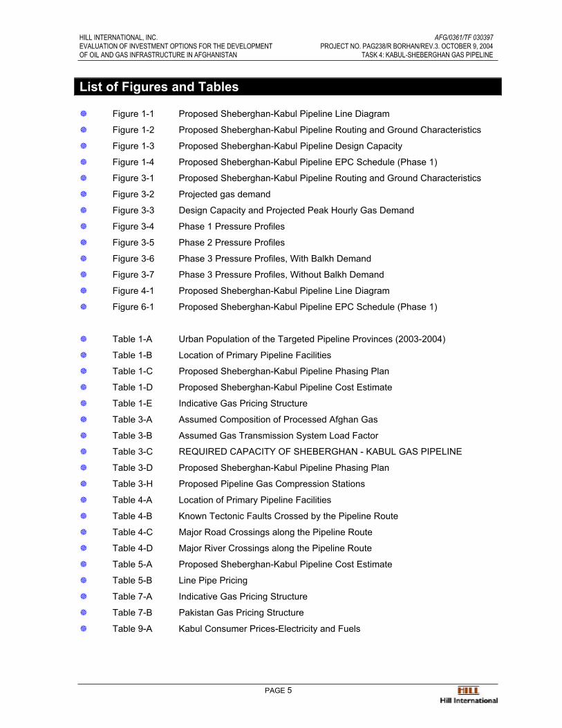
List of Figures and Tables
� Figure 1-1 Proposed Sheberghan-Kabul Pipeline Line Diagram
� Figure 1-2 Proposed Sheberghan-Kabul Pipeline Routing and Ground Characteristics
� Figure 1-3 Proposed Sheberghan-Kabul Pipeline Design Capacity
� Figure 1-4 Proposed Sheberghan-Kabul Pipeline EPC Schedule (Phase 1)
� Figure 3-1 Proposed Sheberghan-Kabul Pipeline Routing and Ground Characteristics
� Figure 3-2 Projected gas demand
� Figure 3-3 Design Capacity and Projected Peak Hourly Gas Demand
� Figure 3-4 Phase 1 Pressure Profiles
� Figure 3-5 Phase 2 Pressure Profiles
� Figure 3-6 Phase 3 Pressure Profiles, With Balkh Demand
� Figure 3-7 Phase 3 Pressure Profiles, Without Balkh Demand
� Figure 4-1 Proposed Sheberghan-Kabul Pipeline Line Diagram
� Figure 6-1 Proposed Sheberghan-Kabul Pipeline EPC Schedule (Phase 1)
� Table 1-A Urban Population of the Targeted Pipeline Provinces (2003-2004)
� Table 1-B Location of Primary Pipeline Facilities
� Table 1-C Proposed Sheberghan-Kabul Pipeline Phasing Plan
� Table 1-D Proposed Sheberghan-Kabul Pipeline Cost Estimate
� Table 1-E Indicative Gas Pricing Structure
� Table 3-A Assumed Composition of Processed Afghan Gas
� Table 3-B Assumed Gas Transmission System Load Factor
� Table 3-C REQUIRED CAPACITY OF SHEBERGHAN - KABUL GAS PIPELINE
� Table 3-D Proposed Sheberghan-Kabul Pipeline Phasing Plan
� Table 3-H Proposed Pipeline Gas Compression Stations
� Table 4-A Location of Primary Pipeline Facilities
� Table 4-B Known Tectonic Faults Crossed by the Pipeline Route
� Table 4-C Major Road Crossings along the Pipeline Route
� Table 4-D Major River Crossings along the Pipeline Route
� Table 5-A Proposed Sheberghan-Kabul Pipeline Cost Estimate
� Table 5-B Line Pipe Pricing
� Table 7-A Indicative Gas Pricing Structure
� Table 7-B Pakistan Gas Pricing Structure
� Table 9-A Kabul Consumer Prices-Electricity and Fuels
HILL INTERNATIONAL, INC. AFG/0361/TF 030397EVALUATION OF INVESTMENT OPTIONS FOR THE DEVELOPMENT PROJECT NO. PAG238/R BORHAN/REV.3. OCTOBER 9, 2004OF OIL AND GAS INFRASTRUCTURE IN AFGHANISTAN TASK 4: KABUL-SHEBERGHAN GAS PIPELINE
PAGE 6
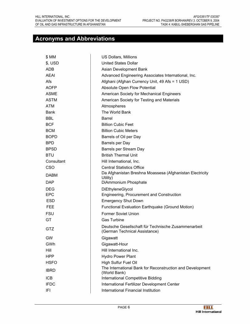
Acronyms and Abbreviations
$ MM US Dollars, Millions$, USD United States DollarADB Asian Development BankAEAI Advanced Engineering Associates International, Inc.Afs Afghani (Afghan Currency Unit, 49 Afs = 1 USD)AOFP Absolute Open Flow PotentialASME American Society for Mechanical EngineersASTM American Society for Testing and MaterialsATM AtmospheresBank The World BankBBL BarrelBCF Billion Cubic FeetBCM Billion Cubic MetersBOPD Barrels of Oil per DayBPD Barrels per DayBPSD Barrels per Stream DayBTU British Thermal UnitConsultant Hill International, Inc.CSO Central Statistics Office
DABM Da Afghanistan Breshna Moassesa (Afghanistan Electricity Utility)
DAP DiAmmonium Phosphate
DEG DiEthyleneGlycolEPC Engineering, Procurement and ConstructionESD Emergency Shut DownFEE Functional Evaluation Earthquake (Ground Motion)
FSU Former Soviet UnionGT Gas Turbine
GTZ Deutsche Gesellschaft für Technische Zusammenarbeit (German Technical Assistance)
GW GigawattGWh Gigawatt-HourHill Hill International Inc.HPP Hydro Power PlantHSFO High Sulfur Fuel Oil
IBRD The International Bank for Reconstruction and Development (World Bank)
ICB International Competitive BiddingIFDC International Fertilizer Development CenterIFI International Financial Institution

HILL INTERNATIONAL, INC. AFG/0361/TF 030397EVALUATION OF INVESTMENT OPTIONS FOR THE DEVELOPMENT PROJECT NO. PAG238/R BORHAN/REV.3. OCTOBER 9, 2004OF OIL AND GAS INFRASTRUCTURE IN AFGHANISTAN TASK 4: KABUL-SHEBERGHAN GAS PIPELINE
PAGE 7
IOC International Oil CompanyIRR Internal Rate of ReturnISBL Inside Battery LimitsKfW Kreditanstalt für WiederaufbauKG KilogramKm KilometerkW KilowattkWh Kilowatt-hourLEL Lower Explosive Limit
LPG Liquefied Petroleum Gas M3 Cubic MetersMAOP maximum allowable operating pressure
MMBO Million Barrels of OilMMBTU Million British Thermal UnitsMMCF Million Cubic FeetMMCM Million Cubic MetersMMI Ministry of Mines and IndustryMMSCF Million Standard Cubic FeetMMSCFD Million Standard Cubic Feet per DayMSCF Thousand Standard Cubic FeetMT Metric TonMW MegawattMWh Megawatt-HourMWP Ministry of Water and Powern.a Not applicableNGO Non-Governmental OrganizationO&M Operation and MaintenanceOSBL Outside Battery LimitsP&ID Piping and Instrumentation Diagram p.a. Per annump.u. Per unit PFD Process Flow DiagramPMT Project Management Team
PPA Power Purchase AgreementPPM Parts Per MillionPRRP Priority Reform and Restructuring ProgramPSI Pounds per Square InchSCADA supervisory control and data acquisition
SCFD Standard Cubic Feet per DaySCMD Standard Cubic Meter per DaySEE Safety Evaluation Earthquake (Ground Motion)
TA Technical Assistance
HILL INTERNATIONAL, INC. AFG/0361/TF 030397EVALUATION OF INVESTMENT OPTIONS FOR THE DEVELOPMENT PROJECT NO. PAG238/R BORHAN/REV.3. OCTOBER 9, 2004OF OIL AND GAS INFRASTRUCTURE IN AFGHANISTAN TASK 4: KABUL-SHEBERGHAN GAS PIPELINE
PAGE 8
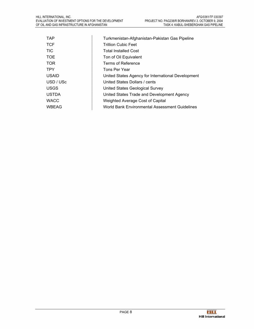
TAP Turkmenistan-Afghanistan-Pakistan Gas PipelineTCF Trillion Cubic FeetTIC Total Installed CostTOE Ton of Oil EquivalentTOR Terms of Reference TPY Tons Per YearUSAID United States Agency for International DevelopmentUSD / USc United States Dollars / cents USGS United States Geological SurveyUSTDA United States Trade and Development AgencyWACC Weighted Average Cost of CapitalWBEAG World Bank Environmental Assessment Guidelines
HILL INTERNATIONAL, INC. AFG/0361/TF 030397EVALUATION OF INVESTMENT OPTIONS FOR THE DEVELOPMENT PROJECT NO. PAG238/R BORHAN/REV.3. OCTOBER 9, 2004OF OIL AND GAS INFRASTRUCTURE IN AFGHANISTAN TASK 4: KABUL-SHEBERGHAN GAS PIPELINE
PAGE 9
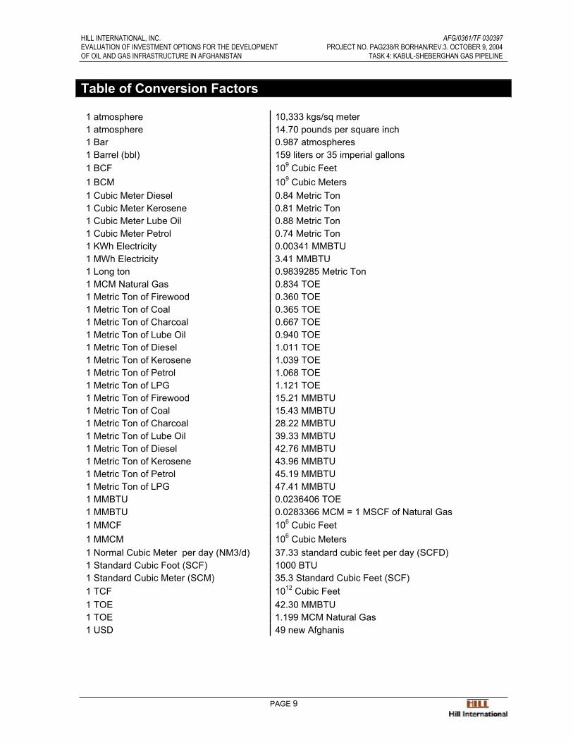
Table of Conversion Factors
1 atmosphere 10,333 kgs/sq meter1 atmosphere 14.70 pounds per square inch1 Bar 0.987 atmospheres1 Barrel (bbl) 159 liters or 35 imperial gallons1 BCF 109 Cubic Feet1 BCM 109 Cubic Meters1 Cubic Meter Diesel 0.84 Metric Ton1 Cubic Meter Kerosene 0.81 Metric Ton1 Cubic Meter Lube Oil 0.88 Metric Ton1 Cubic Meter Petrol 0.74 Metric Ton1 KWh Electricity 0.00341 MMBTU1 MWh Electricity 3.41 MMBTU1 Long ton 0.9839285 Metric Ton1 MCM Natural Gas 0.834 TOE1 Metric Ton of Firewood 0.360 TOE1 Metric Ton of Coal 0.365 TOE1 Metric Ton of Charcoal 0.667 TOE1 Metric Ton of Lube Oil 0.940 TOE1 Metric Ton of Diesel 1.011 TOE1 Metric Ton of Kerosene 1.039 TOE1 Metric Ton of Petrol 1.068 TOE1 Metric Ton of LPG 1.121 TOE1 Metric Ton of Firewood 15.21 MMBTU1 Metric Ton of Coal 15.43 MMBTU1 Metric Ton of Charcoal 28.22 MMBTU1 Metric Ton of Lube Oil 39.33 MMBTU1 Metric Ton of Diesel 42.76 MMBTU1 Metric Ton of Kerosene 43.96 MMBTU1 Metric Ton of Petrol 45.19 MMBTU1 Metric Ton of LPG 47.41 MMBTU1 MMBTU 0.0236406 TOE 1 MMBTU 0.0283366 MCM = 1 MSCF of Natural Gas1 MMCF 106 Cubic Feet1 MMCM 106 Cubic Meters1 Normal Cubic Meter per day (NM3/d) 37.33 standard cubic feet per day (SCFD)1 Standard Cubic Foot (SCF) 1000 BTU1 Standard Cubic Meter (SCM) 35.3 Standard Cubic Feet (SCF)1 TCF 1012 Cubic Feet1 TOE 42.30 MMBTU1 TOE 1.199 MCM Natural Gas1 USD 49 new Afghanis

HILL INTERNATIONAL, INC. AFG/0361/TF 030397EVALUATION OF INVESTMENT OPTIONS FOR THE DEVELOPMENT PROJECT NO. PAG238/R BORHAN/REV.3. OCTOBER 9, 2004OF OIL AND GAS INFRASTRUCTURE IN AFGHANISTAN TASK 4: KABUL-SHEBERGHAN GAS PIPELINE
PAGE 10
The Afghan Calendar
Afghanistan uses the Persian Calendar, which is a solar calendar with a starting point thatmatches that of the Islamic calendar. Its origin can be traced back to the 11th century when a group of astronomers (including the well-known poet Omar Khayyam) created what is known as the Jalaali calendar.
The current calendar has been used in Iran since 1925 and in Afghanistan since 1957.However, Afghanistan used the Islamic calendar in the years 1999-2002.
As in the Islamic calendar, years are counted since Mohammed's emigration to Medina inAD 622. At vernal equinox of that year, AP 1 started (AP = Anno Persico/Anno Persarum =Persian year).
Note that contrary to the Islamic calendar, the Persian calendar counts solar years. In theyear AD 2003 we have therefore witnessed the start of Persian year 1382, but the start ofIslamic year 1424.
The Afghan Year is calculated by subtracting 621 or 622 from the Gregorian year. The year 1382 corresponds to the Gregorian 2003-2004 (March 20 – March 21).

HILL INTERNATIONAL, INC. AFG/0361/TF 030397EVALUATION OF INVESTMENT OPTIONS FOR THE DEVELOPMENT PROJECT NO. PAG238/R BORHAN/REV.3. OCTOBER 9, 2004OF OIL AND GAS INFRASTRUCTURE IN AFGHANISTAN TASK 4: KABUL-SHEBERGHAN GAS PIPELINE
PAGE 11
Sources of Information
The data and analyses presented in this report include information gathered from the followingsources:
1) Interviews by the Hill team and associates with the MMI, the Afghan GasCompany and the Exploration Department in Sheberghan, and verbal orwritten information obtained from these entities.
2) Proprietary geologic and geophysical data obtained from the United StatesGeological Survey.
3) Asian Development Bank Report entitled “Afghanistan – Capacity Building forReconstruction and Development, Gas Sector Rehabilitation”, dated May2003.
4) SOFREGAZ Energy Markets Report entitled “TA-4088-AFG: Energy SectorReview and Gas Development Master Plan”, DRAFT, January 15, 2004,prepared for the Asian Development Bank
5) Norconsult – NORPLAN Association report entitled “Project AFG 03170Power Sector Master Plan Update”, FINAL DRAFT, 16 October 2003,prepared for the Ministry of Water & Power, Afghanistan
6) Government of Afghanistan & International Agency Report entitled “SecuringAfghanistan’s Future: Accomplishments and the Strategic Path Forward”prepared for International Conference, March 31- April 1 2004, by TheGovernment of Afghanistan, The Asian Development, Bank, The UnitedNations Assistance Mission to Afghanistan, The United Nations DevelopmentProgram, and The World Bank Group
7) Report entitled “Petroleum Geology and Resources of Afghanistan” by USGS authors John Kingston and James Clarke, published 1995
8) Report entitled “Geology and Oil and Gas Potential of Northern Afghanistan”prepared by Ministry of Geology of the USSR dated 1970.
9) Document entitled “Gas Potential of Northern Afghanistan – Production Data”,C.Wandrey, USGS Fax of 27 Feb 2004 to A. Oduolowu.
10) Report entitled “Near-Term Oil and Gas Production Rates from SelectedSheberghan Fields”, Gustavson Associates commissioned by HillInternational, April 2004.
11) Acres International Limited Report entitled “Afghanistan Power Sector MasterPlan”, prepared for the Canadian International Development Agency (CIDA),June 1980.
12) Sproule Associates Limited Report entitled “Power Sector Master PlanDevelopment – Energy Resources Availability – Oil and Gas”, June 1979,prepared for Acres International Limited.

HILL INTERNATIONAL, INC. AFG/0361/TF 030397EVALUATION OF INVESTMENT OPTIONS FOR THE DEVELOPMENT PROJECT NO. PAG238/R BORHAN/REV.3. OCTOBER 9, 2004OF OIL AND GAS INFRASTRUCTURE IN AFGHANISTAN TASK 4: KABUL-SHEBERGHAN GAS PIPELINE
PAGE 12
1.0 Executive Summary
1.1 Introduction
This study reviews and outlines the construction and related requirements for a 508Kilometer long natural gas pipeline from the Northern Afghanistan gas fields at Sheberghan,via the towns of Mazar-e-Sharif. Kholm, Baghlan, through the Hindu Kush range ofmountains to Baghram and Kabul. Natural gas will be supplied to the intermediate townsalong the pipeline route, through branch lines and city gate stations. The proposed pipeline will serve over 80% of the country’s urban population1 of 4.6 million inhabitants:
Table 1-A: Urban Population of the Targeted Pipeline Provinces (2003-2004)
Region Province Provincial Capital Urban Population 000’s
Central Parwan Charikar 37
Central Kabul Kabul 2,829
East Nangarhar Jalalabad 102
North East Bughlan Pol-e Khomri 117
North East Kunduz Kunduz 181
North Balkh Mazar-E-Sharif 261
North Jowzjan Sheberghan 51
North Sari Pul Sar-I-Pul 37
North Faryab Meymaneh 84
Total 3,707
Source: CSO 2003 - 2004 Population Statistics
The main transmission pipeline will be constructed of 24” diameter, 0.375” and 0.500” wallthickness, high grade (API 5LX60) longitudinally welded steel pipe, suitable for safe andsecure operation in areas of high seismic activity, notably in the 150 Km. section through the Hindu Kush mountain range, between the towns of Pol-i-Khomri and Baghram where thepipeline crosses eleven major geologic fault lines. Fortunately, welded steel pipelines areremarkably flexible and precautions are taken with the route selection and the pipelinedesign to minimize the effects of seismic activities.
The pipeline will be buried for virtually all of its length at varying depths up to 2m dependingon the terrain. In areas of seismic activity, the axial strains on the pipeline will be reduced by minimum possible burial depth and low-density backfill with no compaction. The use of lowfriction coefficient coatings will allow for sliding at the pipe-soil interface, thereby reducing the friction force transmitted to the pipeline.
1 According to the Central Statistics Office (CSO) of Afghanistan, the current (2003/2004) population of thecountry is 22.2 million. This population includes 4.6 million urban dwellers, 16.1 million rural inhabitants, and 1.5 million nomads.
HILL INTERNATIONAL, INC. AFG/0361/TF 030397EVALUATION OF INVESTMENT OPTIONS FOR THE DEVELOPMENT PROJECT NO. PAG238/R BORHAN/REV.3. OCTOBER 9, 2004OF OIL AND GAS INFRASTRUCTURE IN AFGHANISTAN TASK 4: KABUL-SHEBERGHAN GAS PIPELINE
PAGE 13
For geologic fault crossings, it is envisaged to cross the faults at an angle (between fault and pipeline axis) between 70 to 90 degrees depending on the nature of the fault. Crossingthrust faults will require more care and analysis since the pipe will be compressed and proneto the possibility of local buckling. For the most severe faults, carrying the pipeline aboveground on H-bent supports may be the most suitable option.
A fiber optic cable will be installed in the same trench with the buried pipeline to ensuresecure operational control and communications.
Isolation valves are installed in the pipeline at regular intervals and block valves at majorroad and river crossings for security and maintenance.
As and when the gas field reservoir pressures decline and/or gas demand increases, it willbe necessary to install gas compressors at three locations where interconnections will beprovided for their installation at a later date.
Selected towns along the pipeline are planned to be connected to the pipeline by branchlines to city gate stations.
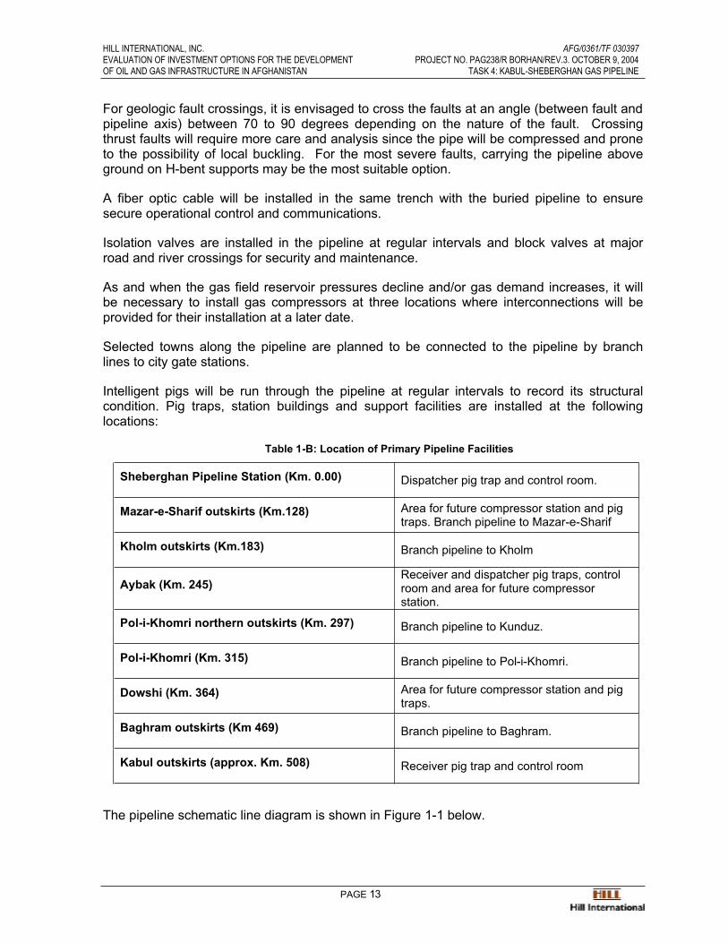
Intelligent pigs will be run through the pipeline at regular intervals to record its structuralcondition. Pig traps, station buildings and support facilities are installed at the followinglocations:
Table 1-B: Location of Primary Pipeline Facilities
Sheberghan Pipeline Station (Km. 0.00) Dispatcher pig trap and control room.
Mazar-e-Sharif outskirts (Km.128) Area for future compressor station and pig traps. Branch pipeline to Mazar-e-Sharif
Kholm outskirts (Km.183) Branch pipeline to Kholm
Aybak (Km. 245)Receiver and dispatcher pig traps, control room and area for future compressor station.
Pol-i-Khomri northern outskirts (Km. 297) Branch pipeline to Kunduz.
Pol-i-Khomri (Km. 315) Branch pipeline to Pol-i-Khomri.
Dowshi (Km. 364) Area for future compressor station and pig traps.
Baghram outskirts (Km 469) Branch pipeline to Baghram.
Kabul outskirts (approx. Km. 508) Receiver pig trap and control room
The pipeline schematic line diagram is shown in Figure 1-1 below.

HILL INTERNATIONAL, INC. AFG/0361/TF 030397EVALUATION OF INVESTMENT OPTIONS FOR THE DEVELOPMENT PROJECT NO. PAG238/R BORHAN/REV.3. OCTOBER 9, 2004OF OIL AND GAS INFRASTRUCTURE IN AFGHANISTAN TASK 4: KABUL-SHEBERGHAN GAS PIPELINE
PAGE 14
Figure 1-1: Proposed Sheberghan-Kabul Pipeline Line Diagram
1.2 The Main Route
The selected main pipeline route commences at a Gas Collection Site south of Sheberghanand ends at a point called Kabul City Gate at Km. 508.
Three alternate route branches were considered during the study with the intention ofreducing pipeline distance or bypassing potentially difficult areas for pipeline construction.Subsequent field surveys confirmed that the main route was most likely to be the easiest interms of construction and logistics. It is envisioned that during the full survey prior to detailed pipeline design, these alternate routes will be revisited.
Figure 1-2 on the following page shows the main pipeline route, the three alternate routes, as well as the ground characteristics along the routing.

HILL INTERNATIONAL, INC. AFG/0361/TF 030397EVALUATION OF INVESTMENT OPTIONS FOR THE DEVELOPMENT PROJECT NO. PAG238/R BORHAN/REV.3. OCTOBER 9, 2004OF OIL AND GAS INFRASTRUCTURE IN AFGHANISTAN TASK 4: KABUL-SHEBERGHAN GAS PIPELINE
PAGE 15
Figure 1-2: Proposed Sheberghan-Kabul Pipeline Routing and Ground Characteristics
1.3 Pipeline Capacity
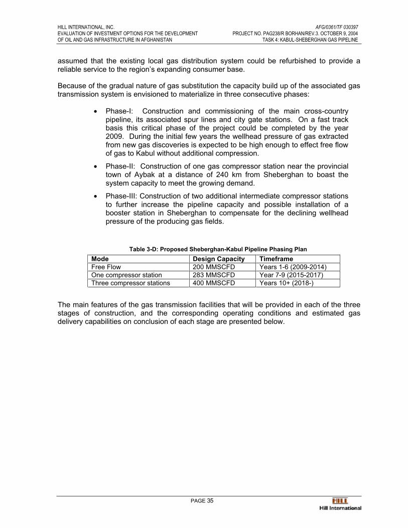
Because of the gradual nature of gas substitution, the capacity build up of the gastransmission system is envisioned to materialize in three consecutive phases:
Main Pipeline RouteAlternate Pipeline Routes

HILL INTERNATIONAL, INC. AFG/0361/TF 030397EVALUATION OF INVESTMENT OPTIONS FOR THE DEVELOPMENT PROJECT NO. PAG238/R BORHAN/REV.3. OCTOBER 9, 2004OF OIL AND GAS INFRASTRUCTURE IN AFGHANISTAN TASK 4: KABUL-SHEBERGHAN GAS PIPELINE
PAGE 16
• Phase-I: Construction and commissioning of the main cross-countrypipeline, its associated spur lines and city gate stations. On a fast trackbasis this critical phase of the project could be completed within 48months. During the initial few years the wellhead pressure of gasextracted from new gas discoveries is expected to be high enough toeffect free flow of gas to Kabul without additional compression.
• Phase-II: Construction of one gas compressor station near the provincialtown of Aybak at a distance of 240 km from Sheberghan to boost thesystem capacity to meet the growing demand.
• Phase-III: Construction of two additional intermediate compressor stations to further increase the pipeline capacity and possible installation of abooster station in Sheberghan to compensate for the declining wellheadpressure of the producing gas fields.
Figure 1-3 below shows the pipeline design capacity and the peak projected hourly gasdemand for the initial 15-years of pipeline operation. A start date of 2009 has been notionallyselected for demonstration purpose as the earliest the pipeline could come on line, assuming construction starts in 2005, and allowing 4 years for construction.
-
5
10
15
20
25
30
35
2009 2010 2011 2012 2013 2014 2015 2016 2017 2018 2019 2020 2021 2022 2023 2024 2025
MM
SC
F /
HR
-
5
10
15
20
25
30
35
MM
SC
F /
HR
THERMAL POWER KABUL NANGARHARPARWAN GHORI BALKHPHASE-I PHASE-II PHASE-IIILINE PACKING POTENTIAL
PHASE-I
PHASE-II
PHASE-IIILINE PACKING
Pipeline Design Capacity
Figure 1-3: Proposed Sheberghan-Kabul Pipeline Design Capacity
The design capacity and development plan for the three Phases of the pipeline aresummarized in Table 1-C below.
HILL INTERNATIONAL, INC. AFG/0361/TF 030397EVALUATION OF INVESTMENT OPTIONS FOR THE DEVELOPMENT PROJECT NO. PAG238/R BORHAN/REV.3. OCTOBER 9, 2004OF OIL AND GAS INFRASTRUCTURE IN AFGHANISTAN TASK 4: KABUL-SHEBERGHAN GAS PIPELINE
PAGE 17
Table 1-C: Proposed Sheberghan-Kabul Pipeline Phasing Plan
Mode Design Capacity TimeframeFree Flow 200 MMSCFD Years 1-6 (2009-2014)One compressor station 283 MMSCFD Year 7-9 (2015-2017)Three compressor stations 400 MMSCFD Years 10+ (2018-)
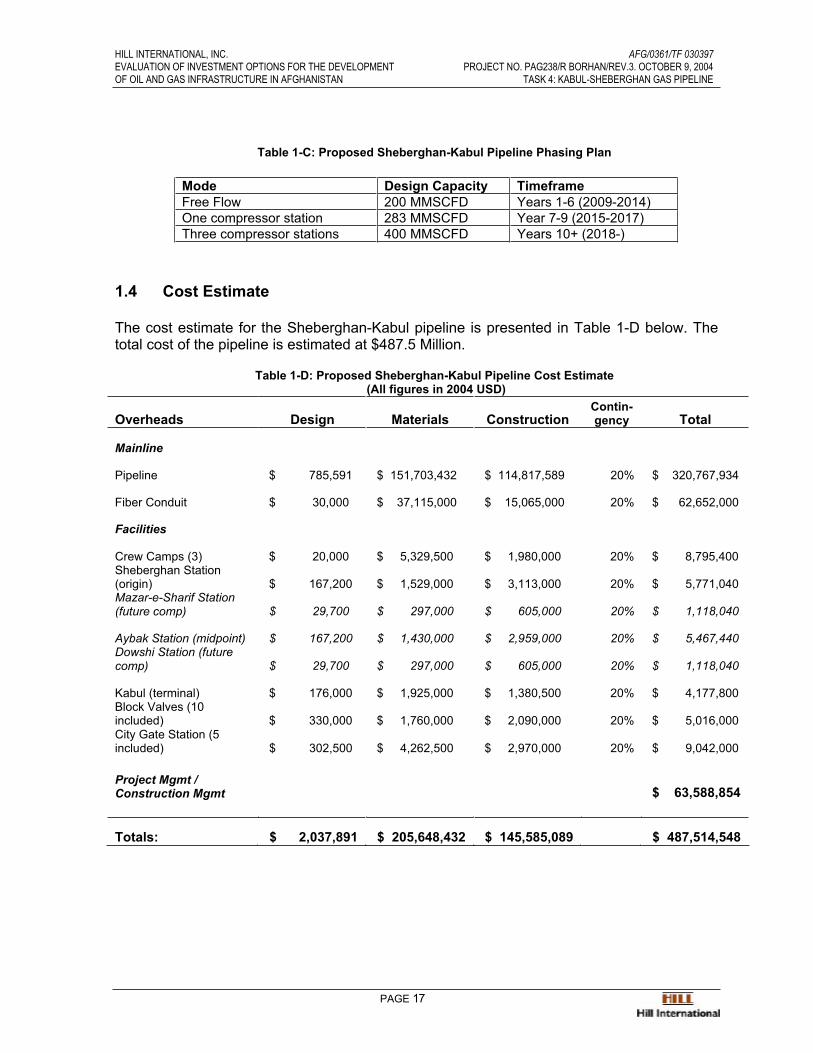
1.4 Cost Estimate
The cost estimate for the Sheberghan-Kabul pipeline is presented in Table 1-D below. Thetotal cost of the pipeline is estimated at $487.5 Million.
Table 1-D: Proposed Sheberghan-Kabul Pipeline Cost Estimate (All figures in 2004 USD)
Overheads Design Materials ConstructionContin-gency Total
Mainline
Pipeline $ 785,591 $ 151,703,432 $ 114,817,589 20% $ 320,767,934
Fiber Conduit $ 30,000 $ 37,115,000 $ 15,065,000 20% $ 62,652,000
Facilities
Crew Camps (3) $ 20,000 $ 5,329,500 $ 1,980,000 20% $ 8,795,400 Sheberghan Station (origin) $ 167,200 $ 1,529,000 $ 3,113,000 20% $ 5,771,040 Mazar-e-Sharif Station (future comp) $ 29,700 $ 297,000 $ 605,000 20% $ 1,118,040
Aybak Station (midpoint) $ 167,200 $ 1,430,000 $ 2,959,000 20% $ 5,467,440 Dowshi Station (future comp) $ 29,700 $ 297,000 $ 605,000 20% $ 1,118,040
Kabul (terminal) $ 176,000 $ 1,925,000 $ 1,380,500 20% $ 4,177,800 Block Valves (10 included) $ 330,000 $ 1,760,000 $ 2,090,000 20% $ 5,016,000 City Gate Station (5 included) $ 302,500 $ 4,262,500 $ 2,970,000 20% $ 9,042,000
Project Mgmt / Construction Mgmt $ 63,588,854
Totals: $ 2,037,891 $ 205,648,432 $ 145,585,089 $ 487,514,548
HILL INTERNATIONAL, INC. AFG/0361/TF 030397EVALUATION OF INVESTMENT OPTIONS FOR THE DEVELOPMENT PROJECT NO. PAG238/R BORHAN/REV.3. OCTOBER 9, 2004OF OIL AND GAS INFRASTRUCTURE IN AFGHANISTAN TASK 4: KABUL-SHEBERGHAN GAS PIPELINE
PAGE 18
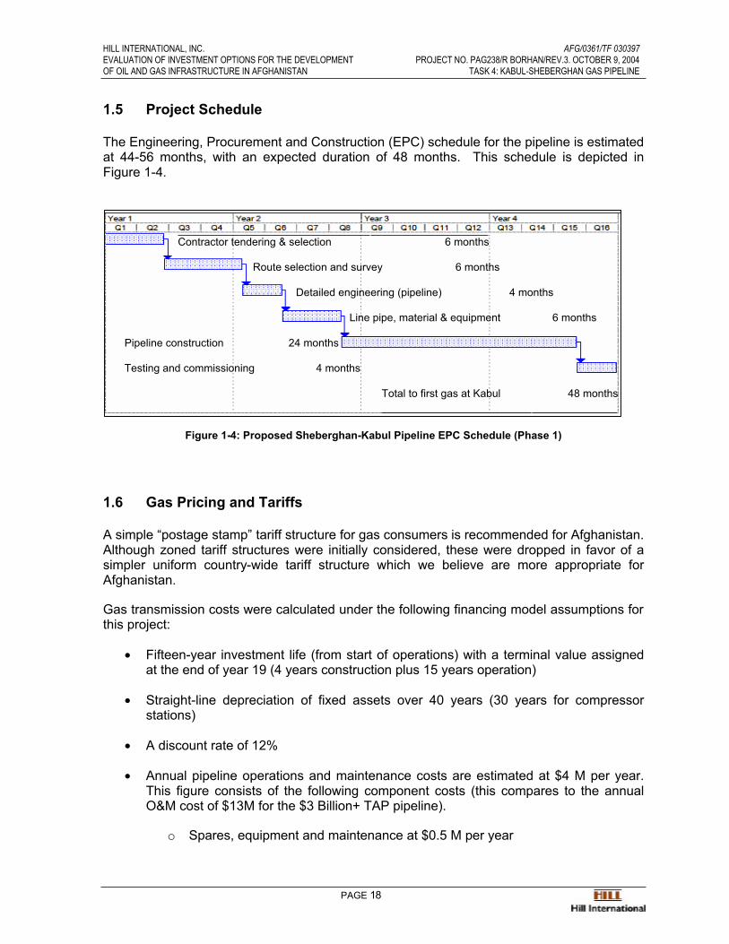
1.5 Project Schedule
The Engineering, Procurement and Construction (EPC) schedule for the pipeline is estimated at 44-56 months, with an expected duration of 48 months. This schedule is depicted inFigure 1-4.
Contractor tendering & selection 6 months
Route selection and survey 6 months
Detailed engineering (pipeline) 4 months
Line pipe, material & equipment 6 months
Pipeline construction 24 months
Testing and commissioning 4 months
Total to first gas at Kabul 48 months
Figure 1-4: Proposed Sheberghan-Kabul Pipeline EPC Schedule (Phase 1)
1.6 Gas Pricing and Tariffs
A simple “postage stamp” tariff structure for gas consumers is recommended for Afghanistan.Although zoned tariff structures were initially considered, these were dropped in favor of asimpler uniform country-wide tariff structure which we believe are more appropriate forAfghanistan.
Gas transmission costs were calculated under the following financing model assumptions for this project:
• Fifteen-year investment life (from start of operations) with a terminal value assignedat the end of year 19 (4 years construction plus 15 years operation)
• Straight-line depreciation of fixed assets over 40 years (30 years for compressorstations)
• A discount rate of 12%
• Annual pipeline operations and maintenance costs are estimated at $4 M per year.This figure consists of the following component costs (this compares to the annualO&M cost of $13M for the $3 Billion+ TAP pipeline).
o Spares, equipment and maintenance at $0.5 M per year

HILL INTERNATIONAL, INC. AFG/0361/TF 030397EVALUATION OF INVESTMENT OPTIONS FOR THE DEVELOPMENT PROJECT NO. PAG238/R BORHAN/REV.3. OCTOBER 9, 2004OF OIL AND GAS INFRASTRUCTURE IN AFGHANISTAN TASK 4: KABUL-SHEBERGHAN GAS PIPELINE
PAGE 19
o Manpower and Overheads at $1.5 M per year
o Utilities at $2.0 M per year
• All figures are on a real pre-tax basis
• Distribution costs have not been calculated in the cost of transmission, and areexpected to be financed out of the distribution margins indicated.
• The total investment cost for the pipeline is taken at $488 M.
• The cost of additional gas compressor stations is incurred the year before thecompressor station begins to operate.
Transmission Cost vs. Discount Rate
0.81
2.06
2.64
3.32
0
0.5
1
1.5
2
2.5
3
3.5
0.00% 5.00% 10.00% 15.00% 20.00%
Discount Rate
Tran
smis
sion
Cos
t USD
per
MSC
F
The average cost of transmission of one MSCF of natural gas is calculated to beapproximately $2.64 using these assumptions. Reducing the discount rate to 10% results inthe average transmission cost dropping to $2.06 per MSCF, while raising it to 15% results ina transmission cost of $3.32.
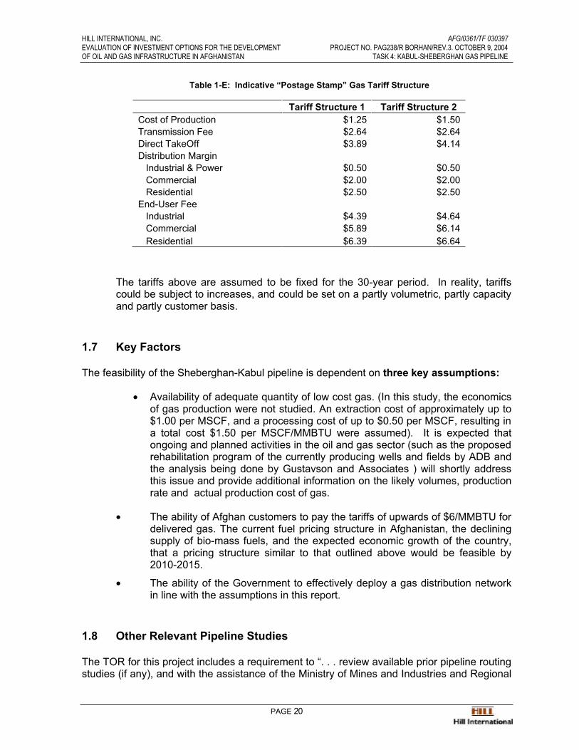
1.6.1 Proposed Tariff Structure
The following table shows two potential tariff structures which differ only in the cost of production, assumed at both $1.25 and $1.50 per MSCF. Both tariff scenariosassume full cost recovery of the pipeline construction and operation costs.
HILL INTERNATIONAL, INC. AFG/0361/TF 030397EVALUATION OF INVESTMENT OPTIONS FOR THE DEVELOPMENT PROJECT NO. PAG238/R BORHAN/REV.3. OCTOBER 9, 2004OF OIL AND GAS INFRASTRUCTURE IN AFGHANISTAN TASK 4: KABUL-SHEBERGHAN GAS PIPELINE
PAGE 20
Table 1-E: Indicative “Postage Stamp” Gas Tariff Structure
Tariff Structure 1 Tariff Structure 2Cost of Production $1.25 $1.50Transmission Fee $2.64 $2.64Direct TakeOff $3.89 $4.14Distribution Margin Industrial & Power $0.50 $0.50 Commercial $2.00 $2.00 Residential $2.50 $2.50
End-User Fee Industrial $4.39 $4.64 Commercial $5.89 $6.14 Residential $6.39 $6.64
The tariffs above are assumed to be fixed for the 30-year period. In reality, tariffscould be subject to increases, and could be set on a partly volumetric, partly capacity and partly customer basis.
1.7 Key Factors
The feasibility of the Sheberghan-Kabul pipeline is dependent on three key assumptions:
• Availability of adequate quantity of low cost gas. (In this study, the economicsof gas production were not studied. An extraction cost of approximately up to$1.00 per MSCF, and a processing cost of up to $0.50 per MSCF, resulting in a total cost $1.50 per MSCF/MMBTU were assumed). It is expected thatongoing and planned activities in the oil and gas sector (such as the proposed rehabilitation program of the currently producing wells and fields by ADB andthe analysis being done by Gustavson and Associates ) will shortly addressthis issue and provide additional information on the likely volumes, productionrate and actual production cost of gas.
• The ability of Afghan customers to pay the tariffs of upwards of $6/MMBTU for delivered gas. The current fuel pricing structure in Afghanistan, the decliningsupply of bio-mass fuels, and the expected economic growth of the country,that a pricing structure similar to that outlined above would be feasible by2010-2015.
• The ability of the Government to effectively deploy a gas distribution networkin line with the assumptions in this report.
1.8 Other Relevant Pipeline Studies
The TOR for this project includes a requirement to “. . . review available prior pipeline routing studies (if any), and with the assistance of the Ministry of Mines and Industries and Regional

HILL INTERNATIONAL, INC. AFG/0361/TF 030397EVALUATION OF INVESTMENT OPTIONS FOR THE DEVELOPMENT PROJECT NO. PAG238/R BORHAN/REV.3. OCTOBER 9, 2004OF OIL AND GAS INFRASTRUCTURE IN AFGHANISTAN TASK 4: KABUL-SHEBERGHAN GAS PIPELINE
PAGE 21
Agencies identify potential route(s) from the gas fields to Kabul . . .” The two relevantcontemporaneous studies the Consultant reviewed are the Sofregaz Energy Sector Reviewand Gas Development Master Plan (TA 4088-AFG” for the Asian Development Bank, and the Penspen report entitled “TAP Natural Gas Pipeline Feasibility Study, Inception Report”, alsofor the ADB.
Much of the information contained in the Penspen Inception Report is of relevance to thisstudy, in that the TAP study initially reviewed and recommended what is referred to as “theNorthern Route” through Afghanistan (the Final Report deals only with the alternate“Southern Route”.) Part of the “Northern Route” includes and roughly coincides with certainsections of route identified, surveyed and analyzed in this study. In the case of the Penspen study, security considerations prevented any field visits within the territory of Afghanistanother than a visit to Kabul. However, the report does provide some valuable backgroundinformation, particularly regarding constructability, environmental and seismic issues, whichcomplement this study.
Similarly, the Sofregaz report includes some information and top-down analysis that concernthe pipeline, prepared as part of the overall Gas Master Plan, including end-user Gas Tariffcalculations based on such a pipeline and good background information on potentialfinancing sources.
HILL INTERNATIONAL, INC. AFG/0361/TF 030397EVALUATION OF INVESTMENT OPTIONS FOR THE DEVELOPMENT PROJECT NO. PAG238/R BORHAN/REV.3. OCTOBER 9, 2004OF OIL AND GAS INFRASTRUCTURE IN AFGHANISTAN TASK 4: KABUL-SHEBERGHAN GAS PIPELINE
PAGE 22
2.0 Terms of Reference
AFGHANISTANEVALUATION OF INVESTMENT OPTIONS FOR THE
DEVELOPMENT OF OIL AND GAS INFRASTRUCTURETerms of Reference for Consulting Services (TF 030397)
C. Terms of Reference for: (ii) the Feasibility of a Gas pipeline from Sheberghan/Mazar-E-Sharif;
Background
C.1. The government plans to increase the availability of power to the city of Kabul based on power generated using the Afghanistan’s natural gas resources, which are located in thenorth of the country. In addition to power generation the Government would like to providegas to industrial, commercial and residential consumers for non-power uses in the city ofKabul as well as the areas along the route of the potential pipeline.
C.2. The gas reserves are estimated at 120-200 billion cubic meters (bcm) or equivalent to 4-7 trillion cubic feet (TCF) in shallow prospects and about 400 (bcm) billion cm (or 14 TCF) in deeper horizons in the northern part of the country. If proven this volume of gas isconsidered to be more than adequate to meet the power and non-power demand of Kabuland other main cities in the north and eastern part of the country. Furthermore, it isanticipated that with increased exploration, additional gas could be found in this area and inother basins around the country. Currently, some of the locally produced gas is used toproduce fertilizer at Sheberghan and also as fuel by household and commercial customersaround Sheberghan and Mazar-E-Sharif.
Objective of Study
(b) Pre-investment feasibility study for the Construction of a gas pipeline to Kabul
(i) evaluate the technical and environmental viability of constructing a pipeline to transportgas from the north to Kabul;
(ii) on the basis of the level of gas demand for Kabul, determine the economic and financialjustification for transporting the gas for power and non-power uses to the Kabul area;
(iii) determine the appropriate size and configuration of the pipeline to be constructed;
(iv) compare the options of generating power either at the existing gas fields in the Mazar-E-Sharif area with the transmission of the power to Kabul as compared to taking the gas toKabul through the pipeline and generate the power at Kabul. The study would evaluate theeconomic benefits of gas utilization for power under both options.
Scope of Study
C.4. To achieve the objectives of the study, the consultant will be expected to :
HILL INTERNATIONAL, INC. AFG/0361/TF 030397EVALUATION OF INVESTMENT OPTIONS FOR THE DEVELOPMENT PROJECT NO. PAG238/R BORHAN/REV.3. OCTOBER 9, 2004OF OIL AND GAS INFRASTRUCTURE IN AFGHANISTAN TASK 4: KABUL-SHEBERGHAN GAS PIPELINE
PAGE 23
(i) determine the appropriate volume of gas to be transported and the corresponding size and characteristics of the pipeline.
(ii) review available prior pipeline routing studies (if any), and with the assistance of theMinistry of Mines and Industries and Regional Agencies identify potential route(s) from thegas fields to Kabul taking into consideration, the gas supply/ demand profiles analyzed,topographic and geographic considerations, construction risks, and other social andenvironmental factors. For the selected route, the consultant will provide the rationale for itschoice, identify any special considerations that will impact the construction of the pipeline,including but not limited to length and size (pipe line diameter), location of compressionstations and branch spur lines. The report of the survey will include maps, photographs,aerial and on-site surveys of critical areas and any other details that will significantly impactthe construction and costs of the pipeline;
(iii) prepare a conceptual design of the selected pipeline in sufficient detail to allow for thedevelopment of a detailed engineering of the pipeline construction. The consultant shouldpay specific attention to the construction cost estimate component of the pipeline in view ofthe special topographic, environmental and social aspects of the terrain that the pipeline willtraverse; and also the likelihood of gas imports from surrounding countries to complementthe local supply for satisfying the gas demand;
(iv) develop a structure for pricing the gas to various end users; and
(v) identify and explore potential sources of financing for the project taking into consideration the special circumstances of Afghanistan. The consultant should prepare a preferred strategy for the funding of the pipeline by the private sector.
Outputs and Reports
C.5. The consultant firm would be expected to provide the following reports summarizing theresults of the analysis:
• Conceptual design of the pipeline routing including details about length ofpipeline, size (diameter), construction characteristics, etc
• A detailed routing map for the pipeline and other engineering details (such as location of compressor stations, etc)
• Total Estimated Cost for constructing the pipeline including: detailengineering, construction, operational and material costs;
• ??Structure of gas pricing and the basis for the determination of the delivery cost of gas at Kabul in US$/thousand cubic feet (US$/MCF)
• Quantitative and qualitative evaluation of the economic, financial,technical, social and environmental advantages/benefits of the gaspipeline option as compared to building the power plant in the north andtransmitting the power to Kabul.
Schedule of Completion of Tasks

HILL INTERNATIONAL, INC. AFG/0361/TF 030397EVALUATION OF INVESTMENT OPTIONS FOR THE DEVELOPMENT PROJECT NO. PAG238/R BORHAN/REV.3. OCTOBER 9, 2004OF OIL AND GAS INFRASTRUCTURE IN AFGHANISTAN TASK 4: KABUL-SHEBERGHAN GAS PIPELINE
PAGE 24
C.6. The Consultant should propose a detailed timeline for the completion of the study asoutlined above comprising; Phase 1- Completion of the Gas Utilization Study; and Phase 2will comprise the implementation of the pre-investment feasibility study of the pipeline. It isanticipated that the work will be completed within six to nine months after the award of thecontract. The Consultant’s work would be reviewed by representatives of IDA.
HILL INTERNATIONAL, INC. AFG/0361/TF 030397EVALUATION OF INVESTMENT OPTIONS FOR THE DEVELOPMENT PROJECT NO. PAG238/R BORHAN/REV.3. OCTOBER 9, 2004OF OIL AND GAS INFRASTRUCTURE IN AFGHANISTAN TASK 4: KABUL-SHEBERGHAN GAS PIPELINE
PAGE 25
3.0 Pipeline Routing and Configuration
3.1 Background
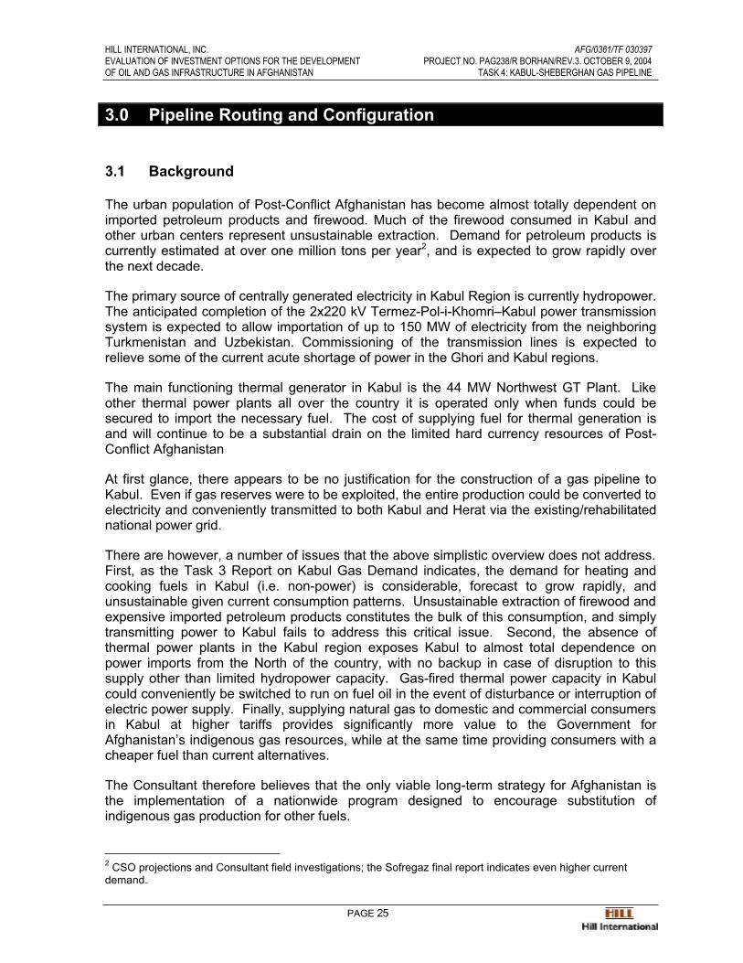
The urban population of Post-Conflict Afghanistan has become almost totally dependent onimported petroleum products and firewood. Much of the firewood consumed in Kabul andother urban centers represent unsustainable extraction. Demand for petroleum products iscurrently estimated at over one million tons per year2, and is expected to grow rapidly overthe next decade.
The primary source of centrally generated electricity in Kabul Region is currently hydropower. The anticipated completion of the 2x220 kV Termez-Pol-i-Khomri–Kabul power transmissionsystem is expected to allow importation of up to 150 MW of electricity from the neighboringTurkmenistan and Uzbekistan. Commissioning of the transmission lines is expected torelieve some of the current acute shortage of power in the Ghori and Kabul regions.
The main functioning thermal generator in Kabul is the 44 MW Northwest GT Plant. Likeother thermal power plants all over the country it is operated only when funds could besecured to import the necessary fuel. The cost of supplying fuel for thermal generation isand will continue to be a substantial drain on the limited hard currency resources of Post-Conflict Afghanistan
At first glance, there appears to be no justification for the construction of a gas pipeline toKabul. Even if gas reserves were to be exploited, the entire production could be converted to electricity and conveniently transmitted to both Kabul and Herat via the existing/rehabilitatednational power grid.
There are however, a number of issues that the above simplistic overview does not address.First, as the Task 3 Report on Kabul Gas Demand indicates, the demand for heating andcooking fuels in Kabul (i.e. non-power) is considerable, forecast to grow rapidly, andunsustainable given current consumption patterns. Unsustainable extraction of firewood and expensive imported petroleum products constitutes the bulk of this consumption, and simplytransmitting power to Kabul fails to address this critical issue. Second, the absence ofthermal power plants in the Kabul region exposes Kabul to almost total dependence onpower imports from the North of the country, with no backup in case of disruption to thissupply other than limited hydropower capacity. Gas-fired thermal power capacity in Kabulcould conveniently be switched to run on fuel oil in the event of disturbance or interruption of electric power supply. Finally, supplying natural gas to domestic and commercial consumers in Kabul at higher tariffs provides significantly more value to the Government forAfghanistan’s indigenous gas resources, while at the same time providing consumers with acheaper fuel than current alternatives.
The Consultant therefore believes that the only viable long-term strategy for Afghanistan isthe implementation of a nationwide program designed to encourage substitution ofindigenous gas production for other fuels.
2 CSO projections and Consultant field investigations; the Sofregaz final report indicates even higher current demand.

HILL INTERNATIONAL, INC. AFG/0361/TF 030397EVALUATION OF INVESTMENT OPTIONS FOR THE DEVELOPMENT PROJECT NO. PAG238/R BORHAN/REV.3. OCTOBER 9, 2004OF OIL AND GAS INFRASTRUCTURE IN AFGHANISTAN TASK 4: KABUL-SHEBERGHAN GAS PIPELINE
PAGE 26
There are compelling reasons to believe that the country’s promising gas prospects wouldvery shortly uncover sufficient reserves to make gas substitution a viable option. A numberof ongoing activities, particularly the Gustavson Associates and USGS effort to establishreserves and production figures and carry out seismic investigations, respectively, will likelyincrease the indigenous gas reserves estimates.
3.1.1 Dependency on Firewood and its Consequences
The Consultant estimates that in Kabul alone nearly one million air dried tons offirewood (approximately 355,000 TOE) are consumed annually, of which 78% isconsumed by the residential sector3. Firewood consumption amounts to 67% of allfuel consumption in the city for purposes other than generating electricity. Only asmall fraction of the firewood consumed in the city can be considered as sustainableextraction. Non-sustainable extraction of firewood is causing irrevocable deforestation of ancient woodlands and desertification of the land on which the rural poor isdependent for their subsistence.
Women and children of the rural poor spend a great deal of time every day in searchof biofuels - the time that could be devoted to productive farming, education and thewellbeing of their families. Recent studies of the economic performance of developing countries have reconfirmed that dependency on biofuels and economic deprivation go hand-in-hand4. In order to break the chain of economic deprivation the ruralpopulation needs access to other forms of energy at an affordable price.
Burning of firewood can also damage people's health as it gives off smoke thatcontains many noxious chemicals. A recent study in Gambia found that children who were carried on their mothers back as they cooked in smoky huts were six times more likely to develop acute respiratory illness than other children.5 Biofuels are also avery inefficient means of cooking compared with kerosene, LPG and natural gas.One ton of kerosene used in modern cooking stoves, for example, can replace about 14 tons of firewood burned in common wood stoves.
As sustained dependency on biofuels is recognized as the major cause of economicdeprivation worldwide, utilization of the country's indigenous gas reserves is bound to play a major role in securing the viable future of Post-Conflict Afghanistan.
3 Source: Core Group Surveys, Sofregaz Report4 Source: “COUNTRY PAPER : PAKISTAN”, Ministry of Petroleum and Natural Resources Pakistan, Regional Seminar on Commercialization of Biomass Technology, 4-8 June 2001, Guangzhou, China5 ibid
HILL INTERNATIONAL, INC. AFG/0361/TF 030397EVALUATION OF INVESTMENT OPTIONS FOR THE DEVELOPMENT PROJECT NO. PAG238/R BORHAN/REV.3. OCTOBER 9, 2004OF OIL AND GAS INFRASTRUCTURE IN AFGHANISTAN TASK 4: KABUL-SHEBERGHAN GAS PIPELINE
PAGE 27
3.2 Overview of the Proposed Gas Transmission System
The proposed gas transmission facilities are intended to provide an integrated gas deliverysystem supplying power stations, large industrial consumers and local gas distributioncenters in Balkh, Ghori and Kabul Regions. The main transmission line starts at the outletflange of a dedicated Gas Processing Plant south of Sheberghan City, the provincial capitalof Jawzjan. As future gas processing options are still to be determined (see Task 1bReport), we have assumed the beginning of the pipeline to be at the location of the currentJarquduk processing plant. The pipeline terminates at a dedicated site in the Kabul IndustrialPark region north of Kabul International Airport. There will be spur lines supplying the maincities, major industries and thermal power plants. The estimated length of the primary routeproposed is 508 kilometers.
3.3 Description of the Pipeline Route
Several potential pipeline routes were initially delineated by cartographic study of availablemaps and tactical pilotage charts, supported by preliminary field observations. A main routewas selected among the several options based on several criteria:
1. Ease of construction of a high-pressure gas transmission line
2. The least amount of access, supply and logistics difficulties
3. Avoidance of areas of habitation and agriculture
4. Shortest route between two points, while servicing as many large population centersalong the route as possible
5. Avoidance of difficult terrain to the extent possible.
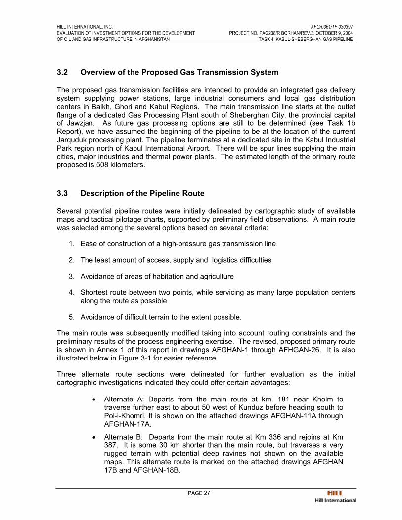
The main route was subsequently modified taking into account routing constraints and thepreliminary results of the process engineering exercise. The revised, proposed primary route is shown in Annex 1 of this report in drawings AFGHAN-1 through AFHGAN-26. It is alsoillustrated below in Figure 3-1 for easier reference.
Three alternate route sections were delineated for further evaluation as the initialcartographic investigations indicated they could offer certain advantages:
• Alternate A: Departs from the main route at km. 181 near Kholm totraverse further east to about 50 west of Kunduz before heading south toPol-i-Khomri. It is shown on the attached drawings AFGHAN-11A through AFGHAN-17A.
• Alternate B: Departs from the main route at Km 336 and rejoins at Km387. It is some 30 km shorter than the main route, but traverses a veryrugged terrain with potential deep ravines not shown on the availablemaps. This alternate route is marked on the attached drawings AFGHAN17B and AFGHAN-18B.
HILL INTERNATIONAL, INC. AFG/0361/TF 030397EVALUATION OF INVESTMENT OPTIONS FOR THE DEVELOPMENT PROJECT NO. PAG238/R BORHAN/REV.3. OCTOBER 9, 2004OF OIL AND GAS INFRASTRUCTURE IN AFGHANISTAN TASK 4: KABUL-SHEBERGHAN GAS PIPELINE
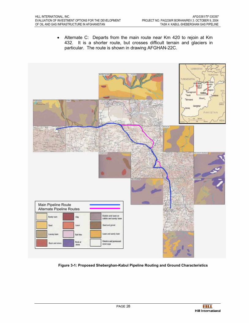
PAGE 28
• Alternate C: Departs from the main route near Km 420 to rejoin at Km432. It is a shorter route, but crosses difficult terrain and glaciers inparticular. The route is shown in drawing AFGHAN-22C.
Figure 3-1: Proposed Sheberghan-Kabul Pipeline Routing and Ground Characteristics
Main Pipeline RouteAlternate Pipeline Routes

HILL INTERNATIONAL, INC. AFG/0361/TF 030397EVALUATION OF INVESTMENT OPTIONS FOR THE DEVELOPMENT PROJECT NO. PAG238/R BORHAN/REV.3. OCTOBER 9, 2004OF OIL AND GAS INFRASTRUCTURE IN AFGHANISTAN TASK 4: KABUL-SHEBERGHAN GAS PIPELINE
PAGE 29
3.3.1 The Primary Route
The selected route commences at the current Jarquduk gas processing facility southof Sheberghan and heads due east across a comparatively flat terrain, passing south of Bargah (Km. 67) and from there along the existing underground pipeline to a point at south west of Emam Saheb (Km. 71), thence departing from the existingunderground pipeline the route heads due east passing from a point at south ofDehdadi and north of a nearby Airport (Km. 117). From Sheberghan to this point theland is flat, arid and dry. There is only one river crossing at Km 110. From this pointthe route heads east passing the south of Mazar-e-Sharif, from Km.126 to Km.130,then proceeding due east passing the south of Mazar-e-Sharif Airport (Km. 136), and south of Gur-e Mar to a point at Km 157, thence due south-east to the city of Kholm.
From the city of Kholm the route heads due south east, through a deep valley, mostly along the existing road that connects Mazar-e-Sharif to Kabul. From Km. 181 atKholm to Km. 201 the proposed route exits the valley. There are two road crossingsand two river crossings.
From Km 201 the valley becomes wide and flat, and the route heads south-eastalong the west side of the existing road, passing Aybak at Km. 240, and Robatak atKm. 277 to a point at a village called Urgurak (Km. 297). This is the junction point toAlternate A.
From Km. 297 the route heads due south, along the existing road, passing a villagecalled Duri Ye Dovvom, to a point at Km. 306, then it continuous south along theexisting road to Pol-i-Khomri (Km. 315), due south to a point (km. 336.7) which is the departing point of Alternate B. From this point the route heads south-west mostlyalong or close by the existing road to Dowshi (Km. 363), then due east along the said road to Km 384, where the route departs from the existing road. In this section thereare 4 river crossings and 4 road crossings.
From Km. 384 the route continue due east to the junction point of Alternate B (Km.387.4), thence due east to Km. 395 at south of Margah, then due south, along theedge of a deep valley called “Darai Chaharmaghzzar” to Km. 420 (departing point ofAlternate C), thence due south-west to the highest point at Km. 425 at elevation 3810m., then due south-east to Km. 432 (junction point of Alternate C), then due south toKm. 446. The terrain in this section is mountainous with small stream crossings.
From Km. 446 the route continues due south alongside the existing road to Kabulthrough a very deep valley to a point to the west of Jabal-Os-Saraj (Km. 460). Theterrain in this section is also mountainous and the valley is so narrow that for mostpart, the route has to stay at the edge of the road. There are 3 river and 3 roadcrossings at this section.
From Jabal-Os-Saraj to Kabul the terrain is flat and mostly farmlands with a lot ofirrigation canals and streams. From Jabal-Os-Saraj the proposed route heads duesouth parallel to the power line, with far enough distance from power line to avoidpipeline corrosion, to a point called Kabul City Gate at Km. 508.
HILL INTERNATIONAL, INC. AFG/0361/TF 030397EVALUATION OF INVESTMENT OPTIONS FOR THE DEVELOPMENT PROJECT NO. PAG238/R BORHAN/REV.3. OCTOBER 9, 2004OF OIL AND GAS INFRASTRUCTURE IN AFGHANISTAN TASK 4: KABUL-SHEBERGHAN GAS PIPELINE
PAGE 30
3.3.2 Alternate Route A (Km 181 – Km. 297.7)
This route departs from proposed main route near the city of Kholm (Km. 181) andheads east over deserted land south of existing road to Kunduz to Km 22, thence due south east to Km. 247, thence due south and south east along a four wheel driveaccessible road passing through a hilly area to Km. 295 where Alternate route Areaches a wide valley created by Pol-i-Khomri river. Thereafter it heads due southalong the side of the hills to Km 321 where it rejoins the proposed route.
This route was at first selected as the principal route. However, field investigationsand surveys presented an alternate route for this section which was 33 Km shorterand the new route was therefore selected as the main route.
Because the previous route had already been studied it has been included in thepackage as Alternate A.
3.3.3 Alternate Route B (Km. 336.7 – Km. 387.5)
This route is some 20 km shorter than the main route, but it traverses a very ruggedterrain with potential deep ravines not shown on the available maps. Fieldinvestigations indicated that although this route is traversable, although it maypresent construction difficulties. The Consultant has conservatively chosen to keepthe longer alternative as the primary route. It is anticipated that this route will befurther examined during detailed design, and could potentially reduce investmentcosts by approximately 2%.
Alternate B departs from the proposed route at Km. 336.7 and heads south-eastalong the ridge line and the side of a valley going uphill to Km. 357.5 where the route reaches the highest point at elevation of 2362.m, thence heads due south going down hill along the ridge line to the junction point on proposed line (Km. 387.5)
Compared to the proposed primary pipeline route, this alternate presents thefollowing advantages and disadvantages:
• Alternate B is 21.5 Km. shorter than the primary route.
• The terrain is mountainous, the slopes are sharp, and there are high cliffs.
• The proposed line is alongside of a tertiary, four wheel drive accessibleroad, which could be used as a service road.
• The primary line passes through more inhabited towns, which couldpossibly be future gas consumers.
• A disadvantage of the primary line is that from Km. 362 to Km. 387 theroute is parallel to the Andarab-Mirza Wolang fault line, hence requiringspecial earthquake-resistant construction measures and thus increasedinvestment.
The Consultant has elected to be conservative and include the higher cost primaryroute alternative as the proposed route. It is anticipated that more detailed
HILL INTERNATIONAL, INC. AFG/0361/TF 030397EVALUATION OF INVESTMENT OPTIONS FOR THE DEVELOPMENT PROJECT NO. PAG238/R BORHAN/REV.3. OCTOBER 9, 2004OF OIL AND GAS INFRASTRUCTURE IN AFGHANISTAN TASK 4: KABUL-SHEBERGHAN GAS PIPELINE
PAGE 31
investigations and surveys during the detailed design phase may confirm the viability of Alternate Route B.
3.3.4 Alternate Route C ( Km. 420 – Km. 432)
Alternate Route C departs from the proposed main route at Km. 421 and heads duesouth going uphill to a saddle pass, at Km. 422.5, at an elevation of 3700 m and thenheads due south and downhill to the junction point at Km 432.
This route forms part of the initially delineated Main Route. Close examination of the aerial maps revealed that from Km. 421.5 to Km. 422 there was a snow deposit atnorth side of the saddle pass which looked like a glacier. Field investigationsconfirmed this and in order to avoid this snow deposit, the primary route which was2.6 km longer was selected instead, bypassing the suspect area.
3.4 Pipeline Design Criteria
The conceptual design of the proposed pipeline was based on the following key designparameters.
3.4.1 Gas Composition and Characteristics
The gas entering the pipeline is assumed to be a mixture of non-associated gasesextracted from a multitude of new gas discoveries in the Amu Darya Basin anddelivered to a Central Gas Processing Plant for conversion to a high specificationpipeline quality gas. It is anticipated that over the life of the pipeline, thecharacteristics of the produced gas will undergo substantial variations. However, theprocessed gas delivered to the system shall remain dry, sweet, pipeline qualitynatural gas which is free of all liquids, solids and gum forming substances:
• Water Content : less than 6.5 lb/MSCF• Hydrocarbon Dew Point: below -10oC at any pressure.• Maximum Total Sulphur: one part per million.• Maximum Carbon Dioxide: one percent volume• Heating Value 1012 BTU/SCF
The gas meeting the above requirements would have been stripped of virtually all itsconstituents of hydrocarbons heavier than butane. The composition of the gasassumed in performance of this study was that of processed Afghan gas shown in the following Table 3-A.

HILL INTERNATIONAL, INC. AFG/0361/TF 030397EVALUATION OF INVESTMENT OPTIONS FOR THE DEVELOPMENT PROJECT NO. PAG238/R BORHAN/REV.3. OCTOBER 9, 2004OF OIL AND GAS INFRASTRUCTURE IN AFGHANISTAN TASK 4: KABUL-SHEBERGHAN GAS PIPELINE
PAGE 32
Table 3-A: Assumed Composition of Processed Afghan Gas
Component Mol %Methane 98.43Ethane 1.19Propane .14Butane .08Pentane plus .06Carbon dioxide .10Total 100.00
3.4.2 Load Factor
The overall load factor for the gas transmission system was estimated by considering the variable load factors of future thermal power generators in Kabul and an averageload factor of 30% covering all other gas consumers. The following anticipateddesign load factors were thus generated and used for pipeline design:
Table 3-B: Assumed Gas Transmission System Load Factor
Year Load Factor
2009-2010 39%
2011-2013 40%
2014-2016 39%
2017–2024 38%
3.4.3 Pipeline Capacity
The potential for gas substitution in Kabul and the Northern regions was covered inthe Task 3: Kabul Gas Demand Study report. The results are summarized in thefollowing Table 3-C.
Table 3-C: REQUIRED CAPACITY OF SHEBERGHAN - KABUL GAS PIPELINE
2009 2014 2019 2024 2049Annual Capacity BSCF 14 38 66 102 102
BCM 0.4 1.1 1.9 2.9 2.9Cumulative Throughput BSCF 0 150 418 849 3,391
BCM 4 12 24 96Load Factor 39% 39% 38% 37% 37%Peak Hourly Demand MMSCF/HR 4.0 10.95 19.75 31.0 31.0
MMSCFD 97 263 474 744 744MMCMD 2.7 7.4 13.4 21.1 21.1
HILL INTERNATIONAL, INC. AFG/0361/TF 030397EVALUATION OF INVESTMENT OPTIONS FOR THE DEVELOPMENT PROJECT NO. PAG238/R BORHAN/REV.3. OCTOBER 9, 2004OF OIL AND GAS INFRASTRUCTURE IN AFGHANISTAN TASK 4: KABUL-SHEBERGHAN GAS PIPELINE
PAGE 33
3.4.4 Gas Reserves
The volume of gas consumed during the first 15 years in the life of the gastransmission system is forecasted to reach 849 BSCF or 24 BCM. Assuming thatafter the initial 15 years of growth the demand for gas will remain constant, then therequired forty-year gas reserve will increase to 3,391 BSCF or 96 BCM. If the gasdemand is to continue to grow at a moderate rate of 2.5% per annum, then therequired forty-year gas reserve further increases to 123 BCM.
3.4.5 Operating Pressures
The pipeline will have a maximum allowable operating pressure (MAOP) of 1,100 psig (75 barg). The minimum delivery pressures at all off-takes will be kept high enough to allow delivering pipeline gas to gas turbines drivers without the need for additionalcompression.
The corresponding design pressures are:
• Line Pipes and fittings 82.5 barg
• Valves and flanges ANSI Class 600 (100 barg)
• Welding ends 84 barg
For the purposes of this study, operating conditions are assumed to be 24 hours perday and 365 days per year.
3.4.6 Pipe wall Thickness
The line pipe wall thickness shall be computed in accordance with ASME B31.8Design Code. The line pipe design factor would depend on the classification of thelocal areas traversed by the pipeline. Except for certain crossings and populatedareas the design factor was taken to be 0.72. The line pipe material was assumed tobe API 5L X60.
3.4.7 Pipe Roughness
The pipe roughness has been taken as 0.0018 inch (46 µm), which is what can beexpected from a typical regularly pigged pipeline that has been in service for anumber of years.

HILL INTERNATIONAL, INC. AFG/0361/TF 030397EVALUATION OF INVESTMENT OPTIONS FOR THE DEVELOPMENT PROJECT NO. PAG238/R BORHAN/REV.3. OCTOBER 9, 2004OF OIL AND GAS INFRASTRUCTURE IN AFGHANISTAN TASK 4: KABUL-SHEBERGHAN GAS PIPELINE
PAGE 34
3.4.8 Gas Temperature
The maximum temperature of gas leaving Sheberghan Gas Processing plant wasassumed to be 140 0F (60 0C). Similarly, the maximum temperature of gas leavingany of the three compressor stations was assumed to be 140 0F (60 0C).
3.4.9 Codes and Standards
The pipeline shall be designed in accordance with the following standards:
ANSI/ASME B 31.8 Gas Transmission Piping System
The most prominent applicable codes and standards for the different components ofthe system and construction work are:
ANSI B 16.5 Pipe Flanges and Flanged Fittings
ANSI B 16.9 Factory Made Wrought-Steel Butt-Welded Fittings
ANSI B 16.11 Forged Steel Fittings
ANSI B 16.25 Butt-Welding Ends
ANSI B 36.10 Welded and Seamless Wrought-Steel Pipe
API 5L Specification for Line Pipe
API 6D Specification for Pipeline Valves
API 1104 Welding Of Pipelines and Related Facilities
3.5 Pipeline Hydraulics
In order to determine the most suitable pipeline size, model analyses of the gas deliverycapabilities of the proposed Sheberghan-Kabul pipeline were carried out. With the aid of aninteractive pipeline simulator, a computer model of the proposed Sheberghan-Kabul pipeline was developed and used to study the pipeline performance. The desk study led toestablishment of the required pipeline size at 24 inches, delineation of the optimum locations of the intermediate compressor stations and configuration of the associated gas compression facilities. Initially the exercise was concentrated on determining the most suitable pipelinesize. Once the pipeline size was selected then the study was focused on evaluating theperformance of the gas transmission system during its three stages of development.
In determining the pipeline delivery capacity for Kabul, It was assumed that all thermal power for the Sheberghan-Mazar-E-Sharif region will be provided by generating capacity installednear Sheberghan. Therefore, the region’s demand for pipeline gas was assumed to exclude thermal generation. In Mazar-E-Sharif, Sheberghan and other towns in Jawzjan it was
HILL INTERNATIONAL, INC. AFG/0361/TF 030397EVALUATION OF INVESTMENT OPTIONS FOR THE DEVELOPMENT PROJECT NO. PAG238/R BORHAN/REV.3. OCTOBER 9, 2004OF OIL AND GAS INFRASTRUCTURE IN AFGHANISTAN TASK 4: KABUL-SHEBERGHAN GAS PIPELINE
PAGE 35
assumed that the existing local gas distribution system could be refurbished to provide areliable service to the region’s expanding consumer base.
Because of the gradual nature of gas substitution the capacity build up of the associated gas transmission system is envisioned to materialize in three consecutive phases:
• Phase-I: Construction and commissioning of the main cross-countrypipeline, its associated spur lines and city gate stations. On a fast trackbasis this critical phase of the project could be completed by the year2009. During the initial few years the wellhead pressure of gas extractedfrom new gas discoveries is expected to be high enough to effect free flow of gas to Kabul without additional compression.
• Phase-II: Construction of one gas compressor station near the provincialtown of Aybak at a distance of 240 km from Sheberghan to boast thesystem capacity to meet the growing demand.
• Phase-III: Construction of two additional intermediate compressor stationsto further increase the pipeline capacity and possible installation of abooster station in Sheberghan to compensate for the declining wellheadpressure of the producing gas fields.
Table 3-D: Proposed Sheberghan-Kabul Pipeline Phasing PlanMode Design Capacity TimeframeFree Flow 200 MMSCFD Years 1-6 (2009-2014)One compressor station 283 MMSCFD Year 7-9 (2015-2017)Three compressor stations 400 MMSCFD Years 10+ (2018-)
The main features of the gas transmission facilities that will be provided in each of the threestages of construction, and the corresponding operating conditions and estimated gasdelivery capabilities on conclusion of each stage are presented below.

HILL INTERNATIONAL, INC. AFG/0361/TF 030397EVALUATION OF INVESTMENT OPTIONS FOR THE DEVELOPMENT PROJECT NO. PAG238/R BORHAN/REV.3. OCTOBER 9, 2004OF OIL AND GAS INFRASTRUCTURE IN AFGHANISTAN TASK 4: KABUL-SHEBERGHAN GAS PIPELINE
PAGE 36
Figure 3-2: Projected Gas Demand
Figure 3-3: Design Capacity and Projected Peak Hourly Gas Demand
-
20
40
60
80
100
120
2009 2011 2013 2015 2017 2019 2021 2023 2025
BS
CF /
YE
AR
BALKH
GHORI
PARWAN
NANGARHAR
KABUL
KABU GTCCPOWER PLANTS
-
5
10
15
20
25
30
35
2009 2010 2011 2012 2013 2014 2015 2016 2017 2018 2019 2020 2021 2022 2023 2024 2025
MM
SC
F /
HR
-
5
10
15
20
25
30
35
MM
SC
F /
HR
THERMAL POWER KABUL NANGARHARPARWAN GHORI BALKHPHASE-I PHASE-II PHASE-IIILINE PACKING POTENTIAL
PHASE-I
PHASE-II
PHASE-IIILINE PACKING
Pipeline Design Capacity
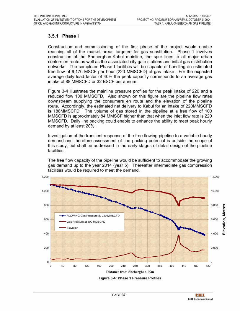
HILL INTERNATIONAL, INC. AFG/0361/TF 030397EVALUATION OF INVESTMENT OPTIONS FOR THE DEVELOPMENT PROJECT NO. PAG238/R BORHAN/REV.3. OCTOBER 9, 2004OF OIL AND GAS INFRASTRUCTURE IN AFGHANISTAN TASK 4: KABUL-SHEBERGHAN GAS PIPELINE
PAGE 37
3.5.1 Phase I
Construction and commissioning of the first phase of the project would enablereaching all of the market areas targeted for gas substitution. Phase 1 involvesconstruction of the Sheberghan-Kabul mainline, the spur lines to all major urbancenters en route as well as the associated city gate stations and initial gas distributionnetworks. The completed Phase I facilities will be capable of handling an estimatedfree flow of 9,170 MSCF per hour (220 MMSCFD) of gas intake. For the expectedaverage daily load factor of 40% the peak capacity corresponds to an average gasintake of 88 MMSCFD or 32 BSCF per annum.
Figure 3-4 illustrates the mainline pressure profiles for the peak intake of 220 and areduced flow 100 MMSCFD. Also shown on this figure are the pipeline flow ratesdownstream supplying the consumers en route and the elevation of the pipelineroute. Accordingly, the estimated net delivery to Kabul for an intake of 220MMSCFD is 188MMSCFD. The volume of gas stored in the pipeline at a free flow of 100MMSCFD is approximately 84 MMSCF higher than that when the inlet flow rate is 220 MMSCFD. Daily line packing could enable to enhance the ability to meet peak hourly demand by at least 20%.
Investigation of the transient response of the free flowing pipeline to a variable hourly demand and therefore assessment of line packing potential is outside the scope ofthis study, but shall be addressed in the early stages of detail design of the pipelinefacilities.
The free flow capacity of the pipeline would be sufficient to accommodate the growing gas demand up to the year 2014 (year 5). Thereafter intermediate gas compressionfacilities would be required to meet the demand.
Distance from Sheberghan, Km
Figure 3-4: Phase 1 Pressure Profiles
0
200
400
600
800
1,000
1,200
0 40 80 120 160 200 240 280 320 360 400 440 480 520-
2,000
4,000
6,000
8,000
10,000
12,000
Elev
atio
n, M
etre
s
FLOWING Gas Pressure @ 220 MMSCFD
Gas Pressure at 100 MMSCFD
Elevation
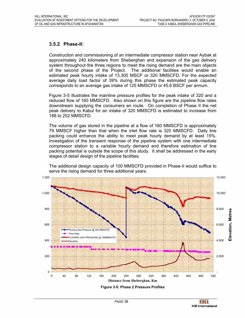
HILL INTERNATIONAL, INC. AFG/0361/TF 030397EVALUATION OF INVESTMENT OPTIONS FOR THE DEVELOPMENT PROJECT NO. PAG238/R BORHAN/REV.3. OCTOBER 9, 2004OF OIL AND GAS INFRASTRUCTURE IN AFGHANISTAN TASK 4: KABUL-SHEBERGHAN GAS PIPELINE
PAGE 38
3.5.2 Phase-II:
Construction and commissioning of an intermediate compressor station near Aybak at approximately 240 kilometers from Sheberghan and expansion of the gas deliverysystem throughout the three regions to meet the rising demand are the main objectsof the second phase of the Project. The additional facilities would enable anestimated peak hourly intake of 13,300 MSCF or 320 MMSCFD. For the expectedaverage daily load factor of 39% during this phase the estimated peak capacitycorresponds to an average gas intake of 125 MMSCFD or 45.6 BSCF per annum.
Figure 3-5 illustrates the mainline pressure profiles for the peak intake of 320 and areduced flow of 160 MMSCFD. Also shown on this figure are the pipeline flow ratesdownstream supplying the consumers en route. On completion of Phase II the netpeak delivery to Kabul for an intake of 320 MMSCFD is estimated to increase from188 to 252 MMSCFD.
The volume of gas stored in the pipeline at a flow of 160 MMSCFD is approximately79 MMSCF higher than that when the inlet flow rate is 320 MMSCFD. Daily linepacking could enhance the ability to meet peak hourly demand by at least 15%.Investigation of the transient response of the pipeline system with one intermediatecompressor station to a variable hourly demand and therefore estimation of linepacking potential is outside the scope of this study. It shall be addressed in the early stages of detail design of the pipeline facilities.
The additional design capacity of 100 MMSCFD provided in Phase-II would suffice toserve the rising demand for three additional years.
Distance from Sheberghan, Km
Figure 3-5: Phase 2 Pressure Profiles
0
200
400
600
800
1,000
1,200
0 40 80 120 160 200 240 280 320 360 400 440 480 520
S
-
2,000
4,000
6,000
8,000
10,000
12,000
Elev
atio
n, M
etre
sFllowing Gas Pressure @ 320 MMSCFD Flow RateFLOWING GAS PRESSURE @ 160MMSCFDElevation

HILL INTERNATIONAL, INC. AFG/0361/TF 030397EVALUATION OF INVESTMENT OPTIONS FOR THE DEVELOPMENT PROJECT NO. PAG238/R BORHAN/REV.3. OCTOBER 9, 2004OF OIL AND GAS INFRASTRUCTURE IN AFGHANISTAN TASK 4: KABUL-SHEBERGHAN GAS PIPELINE
PAGE 39
3.5.3 Phase-III
The facilities to be constructed under this phase include two additional intermediatecompressor stations and the associated expansion of the gas delivery system toenable serving the expanding consumer base. The most suitable location for the first of the two stations is immediately south of Mazar-e-Sharif at a distance of 128kilometers from Sheberghan. The optimum location of the second additionalcompressor station is east of Dowshi at a distance of 362 kilometers fromSheberghan. The addition of these compressor stations is estimated to enhance thepeak hourly intake from 13,300 to 17,670 MSCF or 424 MMSCFD. The average daily load factor the first five years after completion of Phase III is estimated at 38%.Therefore the estimated peak capacity would result in an average gas intake of159.6MMSCFD or 58.3 BSCF per annum.
Figure 3-6 compares the mainline pressure profiles for the peak intake of 424MMSCFD with that of an inlet flow of 160 MMSCFD. On completion of Phase III thenet peak delivery to Kabul for an intake of 424 MMSCFD is estimated to increasefrom 252 to 329 MMSCFD. Utilization of the existing (rehabilitated) smaller gastransmission line from Sheberghan to Mazar-e-Sharif would make it possible tosupply Balkh Province directly and dedicate the freed capacity to Kabul. Figure 3-7illustrates the flowing gas pressure profile for the same inlet flow of 424 MMSCFD,but with no gas deliveries to Mazar-e-Sharif. With this arrangement the supply ofpeak gas to Kabul could increase from 329 to 361 MMSCFD.
Daily line packing could also enhance the ability to meet peak hourly demand, but the presence of three intermediate compressor stations will introduce certain limitations.Nevertheless, assessment of the potential for line packing merits seriousconsideration during the detail design of the pipeline facilities.
The maximum additional design capacity of 120 MMSCFD resulting from completionof Phase-III would suffice the projected demand until 2019. Thereafter, it would bemore cost effective to provide underground gas storage facilities in the vicinity ofKabul than provide additional pipeline capacity. The provision of gas storage wouldallow increasing the pipeline load factor for supply of gas to Kabul from 38% to morethan 80%. At this load factor the annual supply of gas to the region could be morethan doubled. This level of gas supply would suffice the projected demand farbeyond that of the year 2024.

HILL INTERNATIONAL, INC. AFG/0361/TF 030397EVALUATION OF INVESTMENT OPTIONS FOR THE DEVELOPMENT PROJECT NO. PAG238/R BORHAN/REV.3. OCTOBER 9, 2004OF OIL AND GAS INFRASTRUCTURE IN AFGHANISTAN TASK 4: KABUL-SHEBERGHAN GAS PIPELINE
PAGE 40
Distance from Sheberghan, Km
Figure 3-6: Phase 3 Pressure Profiles, With Balkh Demand
Distance from Sheberghan, Km
Figure 3-7: Phase 3 Pressure Profiles, Without Balkh Demand
0
200
400
600
800
1,000
1,200
0 40 80 120 160 200 240 280 320 360 400 440 480 520-
2,000
4,000
6,000
8,000
10,000
12,000
Elev
atio
n, M
etre
s
Flow Rate GAS PRESSURE @ 404 MMSCFDGAS PRESSURE @ 232 MMSCFD Elevation
0
200
400
600
800
1,000
1,200
0 40 80 120 160 200 240 280 320 360 400 440 480 520-
2,000
4,000
6,000
8,000
10,000
12,000
Elev
atio
n, M
etre
s
Fllowing Gas Pressure @ 420 MMSCFD Flow Rate GAS PRESSURE @ 240 MMSCFD Elevation
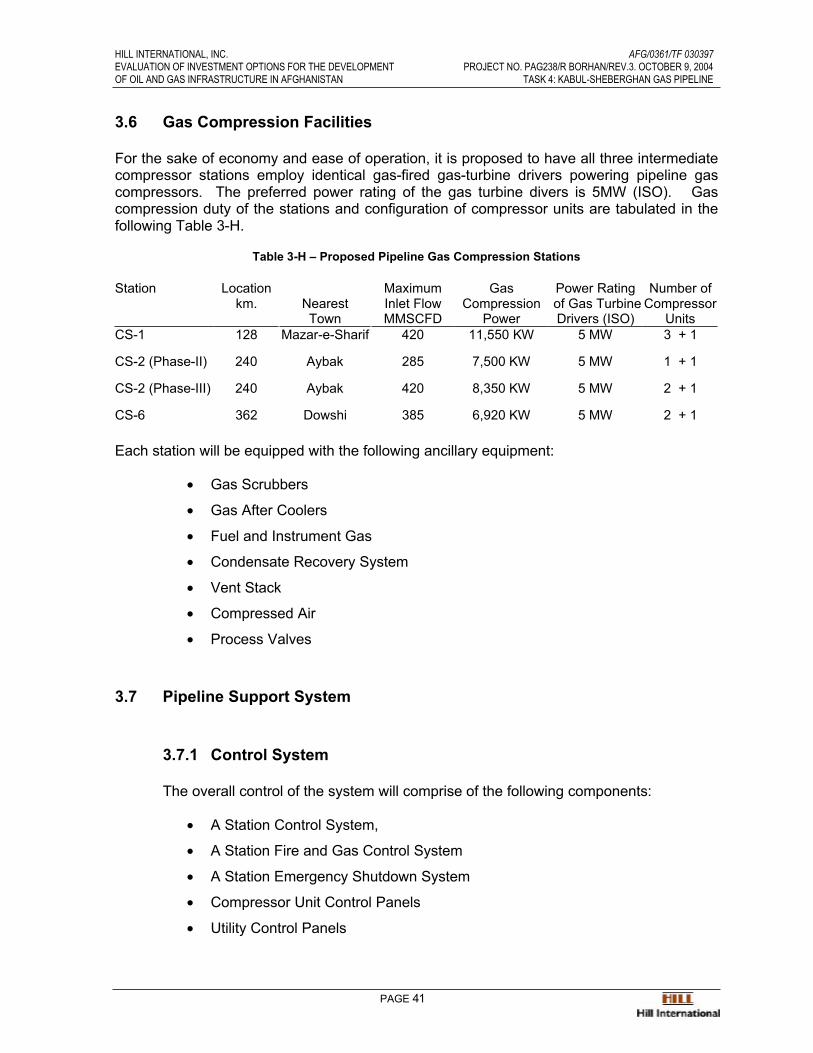
HILL INTERNATIONAL, INC. AFG/0361/TF 030397EVALUATION OF INVESTMENT OPTIONS FOR THE DEVELOPMENT PROJECT NO. PAG238/R BORHAN/REV.3. OCTOBER 9, 2004OF OIL AND GAS INFRASTRUCTURE IN AFGHANISTAN TASK 4: KABUL-SHEBERGHAN GAS PIPELINE
PAGE 41
3.6 Gas Compression Facilities
For the sake of economy and ease of operation, it is proposed to have all three intermediatecompressor stations employ identical gas-fired gas-turbine drivers powering pipeline gascompressors. The preferred power rating of the gas turbine divers is 5MW (ISO). Gascompression duty of the stations and configuration of compressor units are tabulated in thefollowing Table 3-H.
Table 3-H – Proposed Pipeline Gas Compression Stations
Station Locationkm. Nearest
Town
MaximumInlet FlowMMSCFD
GasCompression
Power
Power Rating of Gas Turbine Drivers (ISO)
Number of Compressor
UnitsCS-1 128 Mazar-e-Sharif 420 11,550 KW 5 MW 3 + 1
CS-2 (Phase-II) 240 Aybak 285 7,500 KW 5 MW 1 + 1
CS-2 (Phase-III) 240 Aybak 420 8,350 KW 5 MW 2 + 1
CS-6 362 Dowshi 385 6,920 KW 5 MW 2 + 1
Each station will be equipped with the following ancillary equipment:
• Gas Scrubbers
• Gas After Coolers
• Fuel and Instrument Gas
• Condensate Recovery System
• Vent Stack
• Compressed Air
• Process Valves
3.7 Pipeline Support System
3.7.1 Control System
The overall control of the system will comprise of the following components:
• A Station Control System,
• A Station Fire and Gas Control System
• A Station Emergency Shutdown System
• Compressor Unit Control Panels
• Utility Control Panels

HILL INTERNATIONAL, INC. AFG/0361/TF 030397EVALUATION OF INVESTMENT OPTIONS FOR THE DEVELOPMENT PROJECT NO. PAG238/R BORHAN/REV.3. OCTOBER 9, 2004OF OIL AND GAS INFRASTRUCTURE IN AFGHANISTAN TASK 4: KABUL-SHEBERGHAN GAS PIPELINE
PAGE 42
All systems will communicate with each other and provide selected repeater signalsto the Pipeline SCADA System.
3.7.2 Custody Transfer and Metering
The measurement system employed shall be well tested, internationally approvedand with a predictable measurement uncertainty so that both parties can agree on the quantity and the quality of gas being transferred. It will be based on measuring thevolume and the heating value of the gas at the point of delivery to power stations andmajor consumers and only the volume of gas delivered to all minor consumers.
Turbine Meters shall be used throughout the system. Heating value measurementsshall be carried out by on-line chromatography.
The metering systems shall be designed for initial and intermediate pipelinecapacities, but capable of being expanded to accommodate the final gas flow.
3.7.3 Metering System
The metering system will be designed and constructed as a skid or in parts whichcould be reassembled on site. The finished skids will be bolted to an in-situ concreteslab. The metering skid will be protected from direct solar radiation by means ofsunshades. Each stream will comprise:
• Inlet and outlet pneumatic actuated valves.
• Calibrated meter tube.
• Straightening vanes
• Orifice carrier fitting.
• Stainless steel orifice plate.
• Differential pressure transmitter.
• Pressure transmitter.
• Temperature transmitter.
The number of meter tubes in operation at various gas off-takes will depend on thetotal gas flow and will be switched automatically. The values at which they switche.g., from one to two and from two to one will be determined during detail design.
A gas chromatograph will be located adjacent to its sample point which will beupstream of the meter skid. It will be installed inside an enclosure to protect it fromthe environment. The chromatography control panel will produce a chromatogramand a gas analysis report and calculate the specific gravity and calorific value of thegas passing through the pipeline. This data will be transmitted to all stream flowcomputers via a serial communications link.
HILL INTERNATIONAL, INC. AFG/0361/TF 030397EVALUATION OF INVESTMENT OPTIONS FOR THE DEVELOPMENT PROJECT NO. PAG238/R BORHAN/REV.3. OCTOBER 9, 2004OF OIL AND GAS INFRASTRUCTURE IN AFGHANISTAN TASK 4: KABUL-SHEBERGHAN GAS PIPELINE
PAGE 43
3.7.4 Communications and SCADA
The proposed gas transmission system will have a dedicated communication systemwith comprehensive supervisory control and data acquisition (SCADA) facilities. Theentire pipeline system will be centrally controlled from a Control Center nearSheberghan. The primary objectives of the control center would be:
• Ensure gas demands are met to the limit of system capacity, and shortfallsare shared equally and fairly by all customers on an hourly, daily andmonthly basis.
• Continuously monitor and check the integrity and security of the gassupply system.
• Optimize operating procedures.
• Provide 24 hour emergency response.
• Co-ordinate maintenance activities with operational requirements.
• Reconcile measured quantities for billing purposes.
• Coordinate logistic support.
• Provide management with the required statistics.
3.7.5 Data Monitoring and Control Facility
Line Break Valves
The facility of monitoring line break valves is determined by the form ofcommunication used by the SCADA system. In principle it is desirable to know thestatus of each line break valve and in an emergency to be able to close it remotely.These stations will not normally be manned.
Metering Stations
The status of all equipment together with all measured values will be transmitted tothe central control center. This enables line packing and flow balance to beperformed for the purpose of identifying leaks and also reconciling measuredquantities for billing. In the event of an emergency, it may be necessary to isolate theinlet and outlet of the station. Additionally, it is advantageous to be able to remove ameter stream from service by remote control if there is an obvious discrepancy.
Compressor Stations
The status of all equipment together with all measured values will be transmitted tothe central control. Remote control facilities will include:
• Start/stop of turbo-compressor units.
• Set point values of flow, suction and discharge pressure.

HILL INTERNATIONAL, INC. AFG/0361/TF 030397EVALUATION OF INVESTMENT OPTIONS FOR THE DEVELOPMENT PROJECT NO. PAG238/R BORHAN/REV.3. OCTOBER 9, 2004OF OIL AND GAS INFRASTRUCTURE IN AFGHANISTAN TASK 4: KABUL-SHEBERGHAN GAS PIPELINE
PAGE 44
• Station on/off line.
A compressor station will therefore be capable of operating unmanned, but normally it will be manned.

HILL INTERNATIONAL, INC. AFG/0361/TF 030397EVALUATION OF INVESTMENT OPTIONS FOR THE DEVELOPMENT PROJECT NO. PAG238/R BORHAN/REV.3. OCTOBER 9, 2004OF OIL AND GAS INFRASTRUCTURE IN AFGHANISTAN TASK 4: KABUL-SHEBERGHAN GAS PIPELINE
PAGE 45
4.0 Pipeline Construction
4.1 Introduction
This section reviews and outlines the construction and related logistical requirements for a508 km. long, natural gas pipeline from the Northern Afghanistan gas fields at Sheberghan,via the towns of Mazar-e-Sharif, Kholm, Baghlan, through the Hindu Kush range ofmountains to Baghram and Kabul. Natural gas will be supplied to intermediate towns alongthe pipeline route through branch lines and city gate stations. The pipeline route is shown on the Annex 1 of this report, in drawings AFHGAN-1 through AFGHAN-26.
The main transmission pipeline is proposed to be constructed of 24” diameter, O.375” and0.500” wall thickness, high grade (API 5LX60) longitudinally welded steel pipe, suitable forsafe and secure operation in areas of high seismic activity, notably in the 150 Km. sectionthrough the Hindu Kush mountain range, between the towns of Pol-i-Khomri and Baghramwhere the pipeline crosses eleven major geologic fault lines. Fortunately, welded steelpipelines are remarkably flexible and precautions are taken with the route selection and thepipeline design to minimize the effects of seismic activities.
The pipeline will be buried for virtually all of its length at varying depths up to 2m dependingon the terrain. In areas of seismic activity, the axial strains on the pipeline will be reduced by minimum possible burial depth and low-density backfill with no compaction. The use of lowfriction coefficient coatings will allow for sliding at the pipe-soil interface, thereby reducing the friction force transmitted to the pipeline.
For geologic fault crossings, it is envisaged to cross the faults at an angle (between fault and pipeline axis) between 70 to 90 degrees depending on the nature of the fault. Crossingthrust faults will require more care and analysis since the pipe will be compressed and proneto the possibility of local buckling. For the most severe faults, carrying the pipeline aboveground on H-bent supports may be the most suitable option.
A fiber optic cable will be installed in the same trench with the buried pipeline to ensuresecure operational control and communications.
Isolation valves are installed in the pipeline at regular intervals and block valves at majorroad and river crossings for security and maintenance.
As and when the gas field reservoir pressures decline and/or gas demand increases, it willbe necessary to install gas compressors at three locations where interconnections will beprovided for their installation at a later date.
Selected towns along the pipeline are planned to be connected to the pipeline by branchlines to city gate stations.
Intelligent pigs will be run through the pipeline at regular intervals to record its structuralcondition. Pig traps, station buildings and support facilities are installed at the followinglocations:

HILL INTERNATIONAL, INC. AFG/0361/TF 030397EVALUATION OF INVESTMENT OPTIONS FOR THE DEVELOPMENT PROJECT NO. PAG238/R BORHAN/REV.3. OCTOBER 9, 2004OF OIL AND GAS INFRASTRUCTURE IN AFGHANISTAN TASK 4: KABUL-SHEBERGHAN GAS PIPELINE
PAGE 46
Table 4-A: Location of Primary Pipeline Facilities
Sheberghan Pipeline Station (Km. 0.00) Dispatcher pig trap and control room.
Mazar-e-Sharif outskirts (Km.128)Area for future compressor station and pig traps. Branch pipeline to Mazar-e-Sharif
Kholm outskirts (Km.183) Branch pipeline to Kholm
Aybak (Km. 245)Receiver and dispatcher pig traps, control room and area for future compressor station.
Pol-i-Khomri northern outskirts (Km.297) Branch pipeline to Kunduz.
Pol-i-Khomri (Km. 315) Branch pipeline to Pol-i-Khomri.
Dowshi (Km. 364) Area for future compressor station and pig traps.
Baghram outskirts (Km 469) Branch pipeline to Baghram.Kabul outskirts (approx. Km. 508) Receiver pig trap and control room
The pipeline schematic line diagram is shown in Figure 4-1 below.
Figure 4-1: Proposed Sheberghan-Kabul Pipeline Line Diagram

HILL INTERNATIONAL, INC. AFG/0361/TF 030397EVALUATION OF INVESTMENT OPTIONS FOR THE DEVELOPMENT PROJECT NO. PAG238/R BORHAN/REV.3. OCTOBER 9, 2004OF OIL AND GAS INFRASTRUCTURE IN AFGHANISTAN TASK 4: KABUL-SHEBERGHAN GAS PIPELINE
PAGE 47
4.2 Terrain Description, Seismicity and Fault Lines
4.2.1 Route Description.
The pipeline route has been selected based on terrain topography shown on theaccompanying route location maps and described in the publication ”Terrain Analysisof Afghanistan”, published by East View Cartographic, 2003. Based on theinformation contained in the aforementioned drawings, reference literature and fieldvisits, the nature of the terrain traversed by the pipeline can be classified under thethree route sections and four terrain types, as follows:
• Section I (0 – Km. 315) Sheberghan to Pol-i-Khomri:
Low sandy hills, cultivation in areas adjacent to towns, with rising, sandy androcky hills, and cultivated valleys towards Pol-i-Khomri at the eastern end.
• Section II (Km. 315 – Km. 460) Pol-i-Khomri to Southern foothills:
Narrow valleys with steep rocky/mountains/escarpments, rising from 700m to theSalang pass at 3,800 m. before descending into the southern foothills.
• Section III (Km. 460 – Km. 508) Southern foothills to Kabul:
Rocky foothills, descending into open, sandy valleys and cultivation around Kabul.
4.2.2 Section I terrain
The pipeline route commences at the Sheberghan gas field processing plant andcontinues eastwards through sandy/sand dune terrain for 5/6 Km, and then hillyundulating, rubble and sandy loam, paralleling in places the existing gas pipeline toMazar-e-Sharif, passing to the south of the town, then skirting to the north of thefoothills forming the Kuhe Mir Seyyed mountains and crossing the tributaries formingthe Balk river, 25 Km to the west of Mazar-E-Sharif and continuing on to the town ofKholm through loamy terrain and rubble and loam foothills before crossing the Darya-e-Kholm (Kholm River) south of the town of Kholm (Tashkurgan). Between Kholmand Baghram two route options are considered.
4.2.2.1 Option 1
The western route follows the Darya-e-Kholm river (up to 10 m wide in places)and the asphalted main road from Kholm to Baghlan through a wide valley ofloam and sandy loam terrain, before dropping down into the Kunduz river valley to the south east of Baghlan. (Km. 305) This route is likely to pass through a morepopulated and cultivated terrain and is the preferred option. The length of thisoption is 107 Km.
HILL INTERNATIONAL, INC. AFG/0361/TF 030397EVALUATION OF INVESTMENT OPTIONS FOR THE DEVELOPMENT PROJECT NO. PAG238/R BORHAN/REV.3. OCTOBER 9, 2004OF OIL AND GAS INFRASTRUCTURE IN AFGHANISTAN TASK 4: KABUL-SHEBERGHAN GAS PIPELINE
PAGE 48
4.2.2.2 Option 2
The eastern and longer route skirts the Kuh-i-Bidak (Bidak Mountain) beforeturning south-east through rubble and sandy loam terrain into low mountains anddropping down into the Kunduz river valley at Baghlan. This route provides ashorter branch pipeline into to Kunduz. The length of this option is 127 Km.
From where the two options join near Baghlan, the route passes through theKunduz river valley, which is broad and dissected by numerous rivers andirrigation channels and then crosses the Kunduz river which has a width of 40 to100 m, a depth of 1 m, mainly low banks and a sand and gravel river bed andcontinues through the valley to Pol-i-Khomri (Km. 315).
Up to this point on the pipeline route, there appears to be no significant difficulty in constructing a high pressure gas pipeline using conventional pipeline construction techniques and equipment.
4.2.3 Section II terrain
From Pol-i-Khomri the route follows closely the valley through which the asphaltedmain road and the Pol-i-Khomri river pass, in sand and gravel terrain (the water table in these valleys are 2 to 10 m below the surface). The Pol-i-Khomri river has a widthof 20 – 79 m, the bottom is gravel and rock and the banks are mostly low and flat,from where it continues to the near the town of Daka, (Km. 315), at which point tworoute options are available.
4.2.3.1 Option 1
The route leaves the river valley and enters into the mountain range to the south, rising to an elevation of 1,200 meters. The crests of these ranges are narrow and serrated with sharp peaks. Slopes are mostly steep (20-40 deg.), sometimesprecipitous, with widespread stacks (40-50m high) and the valleys take the formof deep and narrow gorges.
The route descends through mountainous terrain of rubble, sand and rock, intothe Andarab river valley where it rejoins the option 2 route at Km. 386.
4.2.3.2 Option 2
The route follows the Pol-i-Khomri river and the main road to the town of Dowshifrom where it follows the main road and the Andarab river. The Andarab river isup to 50m wide and 1mt deep. The river bed is sand and gravel and rocky inplaces. The banks are high. For this option the pipeline must pass through thenarrow valleys of the Pol-i-Khomri and the Andarab rivers which run alongside the main road. The terrain is rubble and loam with rocky outcrops.

HILL INTERNATIONAL, INC. AFG/0361/TF 030397EVALUATION OF INVESTMENT OPTIONS FOR THE DEVELOPMENT PROJECT NO. PAG238/R BORHAN/REV.3. OCTOBER 9, 2004OF OIL AND GAS INFRASTRUCTURE IN AFGHANISTAN TASK 4: KABUL-SHEBERGHAN GAS PIPELINE
PAGE 49
Crossing the Andarab river, the pipeline route passes into the mountain ranges to the south where it rapidly rises to an elevation of 3,800 m in the vicinity of the SalangPass (Km. 422). Prevailing peaks in this sector of the mountains have elevations inthe range of 2,500 – 5,000m Mountains above 3,500-4,000 m have permanent snowcaps and glaciers.
The crests of mountain ranges are mostly narrow and the peaks are sharp or dome-shaped. Mountainsides are steep (up to 40 degrees slope), sometimes precipitousand dissected by numerous gulleys and ravines. The mountains are crisscrossed bypack-animal trails through narrow valleys and stream beds which the pipeline routetends to follow. In the high peak areas the pipeline route passes throughintermountain valleys having flattish and/or hilly bottoms
Soils in the mountains are rubble and loam underlain with rock which crops out inplaces (on mountaintops and crests of ridges. River valleys have sand and gravelsoils. From the 3,800 m Salang Pass, the pipeline route traverses down similarterrain to an elevation of 1,600 m, before rejoining the main road to Kabul, in a valley 8Km. north of the town of Jabal os Saraj (Km.460).
4.2.4 Section III terrain
From the town of Jabal os Saraj in the southern foothills, the route enters the basin of the Panjshir river and the wide Kabul plain. The bottom of the basin is flat and isdissected by the Panjshir river, many of its tributaries and irrigation canals. ThePanjshir River is 20 – 100 m wide, has low banks and a clayey river bed. Thereafterthe terrain is mainly rubble and loam and densely cultivated for the last 60 Km. to the outskirts of Kabul.
Cultivation and irrigation will contribute to making this Section difficult to access.
4.2.5 Seismicity
The pipeline route traverses three distinct areas of seismic activity; these areas areshown on drawing Afghan – S – 001 and are classified for earthquake purposes, asfollows:
4.2.5.1 Km. 0 – Km. 50: Minor damage probable
There is little risk of damage to either the pipeline or the related facilities fromseismic activities.
4.2.5.2 Km. 50 – Km. 350 Moderate damage probable.
There is little risk of damage to either the pipeline or the related facilities fromseismic activities.
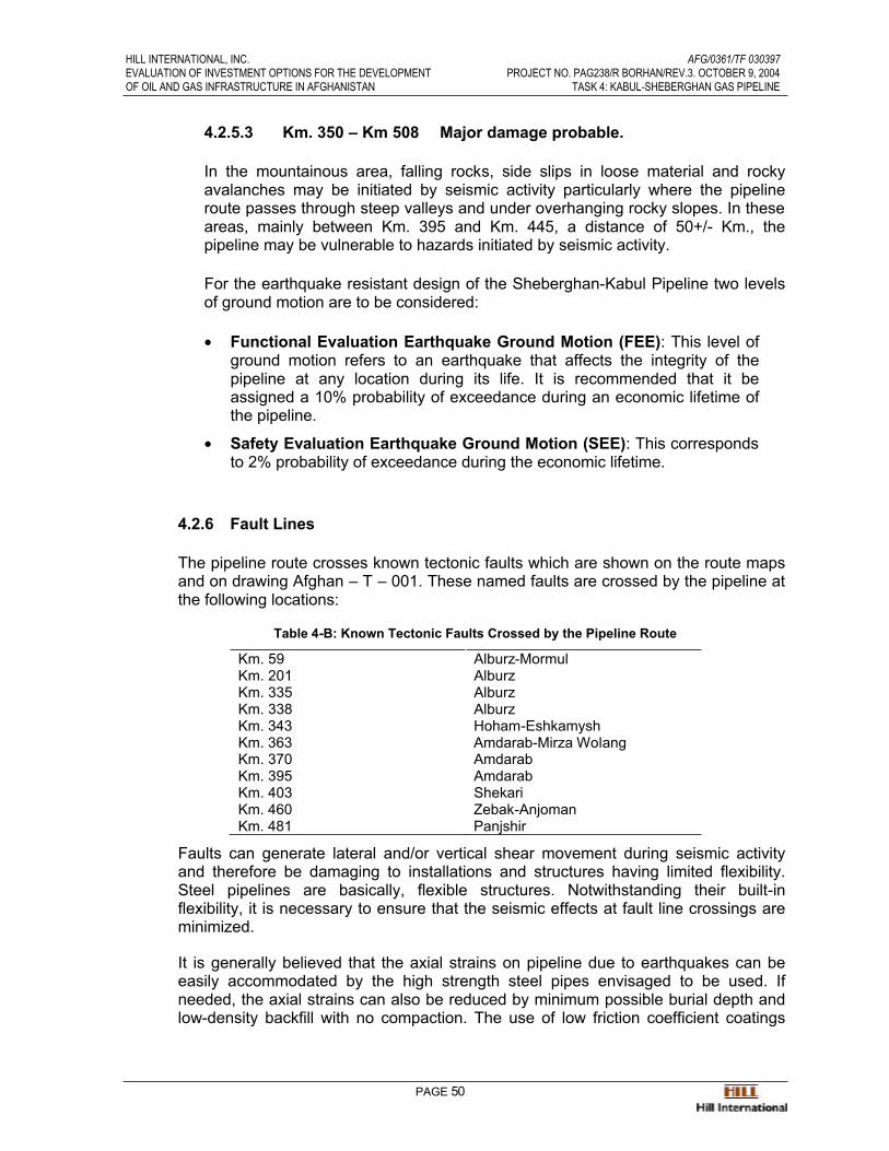
HILL INTERNATIONAL, INC. AFG/0361/TF 030397EVALUATION OF INVESTMENT OPTIONS FOR THE DEVELOPMENT PROJECT NO. PAG238/R BORHAN/REV.3. OCTOBER 9, 2004OF OIL AND GAS INFRASTRUCTURE IN AFGHANISTAN TASK 4: KABUL-SHEBERGHAN GAS PIPELINE
PAGE 50
4.2.5.3 Km. 350 – Km 508 Major damage probable.
In the mountainous area, falling rocks, side slips in loose material and rockyavalanches may be initiated by seismic activity particularly where the pipelineroute passes through steep valleys and under overhanging rocky slopes. In these areas, mainly between Km. 395 and Km. 445, a distance of 50+/- Km., thepipeline may be vulnerable to hazards initiated by seismic activity.
For the earthquake resistant design of the Sheberghan-Kabul Pipeline two levelsof ground motion are to be considered:
• Functional Evaluation Earthquake Ground Motion (FEE): This level ofground motion refers to an earthquake that affects the integrity of thepipeline at any location during its life. It is recommended that it beassigned a 10% probability of exceedance during an economic lifetime ofthe pipeline.
• Safety Evaluation Earthquake Ground Motion (SEE): This corresponds to 2% probability of exceedance during the economic lifetime.
4.2.6 Fault Lines
The pipeline route crosses known tectonic faults which are shown on the route mapsand on drawing Afghan – T – 001. These named faults are crossed by the pipeline at the following locations:
Table 4-B: Known Tectonic Faults Crossed by the Pipeline Route
Km. 59 Alburz-MormulKm. 201 AlburzKm. 335 AlburzKm. 338 AlburzKm. 343 Hoham-EshkamyshKm. 363 Amdarab-Mirza WolangKm. 370 AmdarabKm. 395 AmdarabKm. 403 ShekariKm. 460 Zebak-AnjomanKm. 481 Panjshir
Faults can generate lateral and/or vertical shear movement during seismic activityand therefore be damaging to installations and structures having limited flexibility.Steel pipelines are basically, flexible structures. Notwithstanding their built-inflexibility, it is necessary to ensure that the seismic effects at fault line crossings areminimized.
It is generally believed that the axial strains on pipeline due to earthquakes can beeasily accommodated by the high strength steel pipes envisaged to be used. Ifneeded, the axial strains can also be reduced by minimum possible burial depth andlow-density backfill with no compaction. The use of low friction coefficient coatings
HILL INTERNATIONAL, INC. AFG/0361/TF 030397EVALUATION OF INVESTMENT OPTIONS FOR THE DEVELOPMENT PROJECT NO. PAG238/R BORHAN/REV.3. OCTOBER 9, 2004OF OIL AND GAS INFRASTRUCTURE IN AFGHANISTAN TASK 4: KABUL-SHEBERGHAN GAS PIPELINE
PAGE 51
allows for sliding at the pipe-soil interface, thereby reducing the friction forcetransmitted to the pipeline.
For fault crossings, it would be beneficial to cross the faults at an angle (between fault and pipeline axis) between 70 to 90 degrees depending on the nature of the fault.Crossing thrust faults will require more care and analysis since the pipe will becompressed and prone to the possibility of local buckling. For the most severe faultscarrying the pipeline above ground on H-bent supports could be the most suitableoption.
Provided that appropriate and prudent engineering measures are taken the proposedpipeline route is feasible to cross and can transport safely the natural gas withoutendangering the lives, property and environment.
4.3 Pipeline Safety Features and Systems
The pipeline system will be designed in accordance with ASME standard B31.8 GasTransmission and Distribution Systems and pipe of a grade and wall thickness to meetpipeline transmission pressures and what is necessary to minimize the effects damagecaused by seismic activity.
In the mountain and rocky sectors of Section II, damage to the pipeline from rock falls andlandslides will be minimized by careful routing to avoid potentially hazardous locations andby burying the pipeline to ensure a minimum protective cover of 1 m.
Where it is not possible to construct a secure buried pipeline, consideration will be given tolaying the pipeline above ground, on steel H-bent frames, secured on concrete foundationsbedded into rock, and sheltered by robust, overhead steel or concrete shields.
Where the buried pipeline traverses up or down steep mountainous slopes the it will belocated to avoid watershed gulleys likely to be subject to flash floods and revetted atfrequent intervals direct any flood water away from the pipeline and prevent backfill materialfrom being washed away. Additionally, the pipeline will be secured in place by concreteanchor blocks to prevent movement.
Pipeline block valves are designed to be installed at every 50Km. These are fitted withautomatic shut-down actuators, initiated by the SCADA and leak detection systems, throughthe fiber-optic cable laid alongside the pipeline. Automatic closure of the pipeline blockvalves is initiated by the system on detection of a gas leak or pipeline rupture.
All major rivers and road crossings may be protected by automatic or manually operatedisolation valves.
The leak detection package will be software-based and resides in the SCADA system. Thiscomprises a proprietary, well proven program making use of real time pipeline modeling, flow metering, pressure, temperature and all relevant data available from the pipeline,Sheberghan, Aybak and Kabul terminal stations. The master SCADA system in theSheberghan Pipeline Station control room detects and locates leaks in the pipeline,automatically initiates an ESD and closes the pipeline block valves.

HILL INTERNATIONAL, INC. AFG/0361/TF 030397EVALUATION OF INVESTMENT OPTIONS FOR THE DEVELOPMENT PROJECT NO. PAG238/R BORHAN/REV.3. OCTOBER 9, 2004OF OIL AND GAS INFRASTRUCTURE IN AFGHANISTAN TASK 4: KABUL-SHEBERGHAN GAS PIPELINE
PAGE 52
Running regular intelligent pigs through the pipeline from Sheberghan to Aybak (a distanceof 245 Km.) and from Aybak to Kabul (a distance of 263 Km.) allows the structural conditionof the pipeline to be monitored and recorded. The runs shall be through shorter lengths of the pipeline as and when future compressor and pig trap facilities are installed.
4.4 Seismic Protection, Fault-line Crossings, Road and River Crossings
4.4.1 Seismic Protection
Where the pipeline route cannot by-pass or avoid sectors liable to possible damageresulting from rock falls or avalanches and if it has to be laid above-ground thenreinforced concrete shields will be constructed over the pipeline If it is possible tobury the pipeline in these sectors, they will be laid in trenches cut into virgin rock andbackfilled with a lean concrete mix.
4.4.2 Fault-line Crossings
At fault-line crossings the pipeline will be laid above-ground on a series of steel H-bent structures spaced at 10m intervals and piled into the ground. The pipelinealignment will be made at an angle of 45º to the line of the fault and the pipeline wall thickness is increased from 0.375” to 0.5”.
The H-bent crossing extends across to either side of the fault and the pipeline restsunrestrained, on steel slip plates welded to the horizontal member of the H-bent andthe underside of the pipeline, allowing freedom of horizontal and vertical movement.Depending on the length of the crossing, the pipeline may require restraining halfway.
At either side of the fault crossing, the pipeline will be secured by concrete anchorblocks.
4.4.3 Road and River Crossings
4.4.3.1 Roads
Major road pipeline crossings are laid through vented, steel sleeves laid with 1.5meters of cover under the road and extending a minimum of 5m on either side.The pipeline is laid through Williamson-type insulators inside the steel sleeve and the ends of the sleeve are sealed. The fiber-optic cable is pulled through a50/100mm. coated steel pipe laid adjacent to the steel sleeve and the trenchbackfilled with a lean mix concrete.

HILL INTERNATIONAL, INC. AFG/0361/TF 030397EVALUATION OF INVESTMENT OPTIONS FOR THE DEVELOPMENT PROJECT NO. PAG238/R BORHAN/REV.3. OCTOBER 9, 2004OF OIL AND GAS INFRASTRUCTURE IN AFGHANISTAN TASK 4: KABUL-SHEBERGHAN GAS PIPELINE
PAGE 53
Manual or automatic operation isolation valves may be installed on both sides ofthe crossing.
From information gathered during the field visits and examination of aerial maps,the following roads requiring this treatment are as follows:
Table 4-C: Major Road Crossings along the Pipeline Route
Km. 6 Sheberghan – Sar-i-Pul.Km. 110 Mazar-e-Sharif – Sari-Asya – south.Km. 117 Mazar-e-Sharif – Airport.Km. 127 Mazar-e-Sharif – south.Km. 180 Mazar-e-Sharif – Kholm.Km. 185 – 281 6 crossings Kholm – Baghlan.Km. 322 – 342 3 crossings Pol-i-Khomri – Dowshi.Km. 365 – 452 5 crossings Dowshi – Jabal os Saraj.Km. 460 Jabal os Saraj – GolbaharKm. 465 Golbahar – CharikarKm. 480 Charikar – Baghram.Km. 482 Baghram – Kabul.
All other minor roads/tracks shall be crossed by deepening the trench to increase the pipeline cover to 1.5m
4.4.3.2 Rivers
Major river crossings are “open cut” and the pipeline installed with concreteweight coating to secure it in position. The pipeline will be installed with aminimum of 2m of cover below the river bed. The river banks at the crossing willbe revetted to prevent erosion and the pipeline secured in the trench on eitherside, by concrete anchor blocks.
The fiber optic cable is pulled through a 50/100mm. coated steel pipe secured tothe pipeline concrete weight coating by stainless steel bands
Consideration will be given to the installation of manual or automatic operationisolation valves on either side of the river crossing.
Major river crossings are as follows:
Table 4-D: Major River Crossings along the Pipeline Route
Km.110 Balkh river, near Mazar-e-SharifKm.185 Darya-e-Kholm river, near KholmKm.195 Darya-e-Kholm river, near KholmKm. 217 Darya-e-Kholm river, near KholmKm. 317 Pol-i-Khomri river.Km. 364 Darya-e-Andarab river.Km. 466 Panjshir river.
In Section II, narrow and deep ravines will be crossed on suspension or H-bentbridges to ensure safety and to allow the construction and installation of long

HILL INTERNATIONAL, INC. AFG/0361/TF 030397EVALUATION OF INVESTMENT OPTIONS FOR THE DEVELOPMENT PROJECT NO. PAG238/R BORHAN/REV.3. OCTOBER 9, 2004OF OIL AND GAS INFRASTRUCTURE IN AFGHANISTAN TASK 4: KABUL-SHEBERGHAN GAS PIPELINE
PAGE 54
radius pipe bends that allow intelligent pigs to pass through the pipeline. Thealignment and design of these bridge crossings will depend upon topography,potential rock falls and avalanches.
4.5 Habitation and Agriculture
Information regarding agricultural development and areas of habitation are shown in theaccompanying route location drawings and will be further investigated during detailed design survey.
In general terms, the pipeline is located to ensure the shortest route whilst avoiding areas of habitation and agriculture. The standards used for the identification of pipeline designrequirements in built-up areas of habitation shall conform to ASME B31.8 Gas Transmission and Distribution Systems.
The pipeline will traverses areas of agricultural development where crop damage may occuras a result of construction activities. The extent and nature of such damage made by ROWand pipeline construction activities and the compensation required must be discussed withthe landowner/tenant in advance of construction activity. Agricultural development iscentered mainly on the towns and villages along the pipeline route in Sections I and II.
The detailed design survey team will mark the pipeline route and the locations where itpasses through cultivated land. Prior to the commencement of construction activities, thePMT’s ROW & Land Acquisition Officer shall contact the landowner, identify the extent of the crop being cultivated and conclude an agreement for compensation and permission for thepipeline to be constructed across his land.
4.6 Access Roads and Storage Sites.
4.6.1 Access Roads
Access for pipeline construction spreads in Sections I & III is mostly provided by the20/25m wide ROWs. There are numerous crossing tracks in these sections which can be used to provide access for the transportation of construction personnel andmaterials to the construction worksites.
In Section II and where the pipeline route is close to the main road, this will be usedfor access to the pipeline construction worksites.
Where the pipeline passes into the mountains, the ROW will be used for access tothe pipeline construction worksites, which can be spread over several kilometers. Itwill however, be necessary to construct access roads around steep ROW grades and narrow gorges. These access roads may be constructed to follow the many packanimal tracks that exist throughout the mountains or new access roads may be found to be necessary.
HILL INTERNATIONAL, INC. AFG/0361/TF 030397EVALUATION OF INVESTMENT OPTIONS FOR THE DEVELOPMENT PROJECT NO. PAG238/R BORHAN/REV.3. OCTOBER 9, 2004OF OIL AND GAS INFRASTRUCTURE IN AFGHANISTAN TASK 4: KABUL-SHEBERGHAN GAS PIPELINE
PAGE 55
4.6.2 Storage Sites
Throughout the length of the pipeline, storage sites/depots will be established atstrategic locations, close to the main road and pipeline for line pipe to be off-loadedfrom conventional road transport, pipe semi-trailer vehicles and stored for subsequentre-loading as required, onto smaller construction vehicles. The line pipe will then betransported and strung along the pipeline ROW. (Line-pipe is usually manufactured in 10/12m lengths and the semi-trailer vehicle is a long vehicle requiring good access),
Other permanent and construction materials such as valves, flanges and fittings andpipeline construction consumables will be stored in a secure site/depot locationadjacent to the construction spread camps which are located within 1 -2 hours drivefrom the main pipeline construction spread work sites.
4.7 Terrain Protection And Restoration
Protection and restoration of the natural terrain along the proposed Sheberghan-KabulPipeline Route Corridor shall be prime consideration during construction and commissioningof the pipeline. Guidelines shall be developed at the onset of the construction phasecovering:
• Protection of the naturally existing conditions as much as possible takingprecautions before the construction of the pipeline where necessary;
• Protection of the construction sites against erosion and avalanche;
• Mitigation of the potential impacts on topography and landscape;
• Mitigation of the potential impacts on natural drainage;
• Restoration after soil removal or spoil;
• Restoration of quarries and soil storage sites;
• Restoration of special areas, e. g., residential areas, agricultural areas,surface water bodies, pasture lands, etc., after construction;
• Restoration of special crossings, i.e., roads, railways, rivers, irrigation anddrainage channels, after construction;
• Restoration of terrain through which the access roads pass; and
• Restoration of pipe storage yards and construction camps.
4.7.1 Terrain Protection and Mitigation Measures
The pipeline design, construction techniques and operating practices should bebased on minimizing surface disturbance and effects on other resources, andmaintaining reclamation potential of the construction area. Therefore, this sectioncovers measures against possible terrain disturbances that can result from pipeline

HILL INTERNATIONAL, INC. AFG/0361/TF 030397EVALUATION OF INVESTMENT OPTIONS FOR THE DEVELOPMENT PROJECT NO. PAG238/R BORHAN/REV.3. OCTOBER 9, 2004OF OIL AND GAS INFRASTRUCTURE IN AFGHANISTAN TASK 4: KABUL-SHEBERGHAN GAS PIPELINE
PAGE 56
construction activities regardless of the jurisdiction on the specific land involved.Therefore, it would be necessary to incorporate the necessary measures against:
• Soil erosion,
• impacts on existing drainage courses,
• pollution due to construction activities,
• impacts of storage facilities,
• environmental problems regarding quarries.
The general conditions of the mountainous section of the route indicate that erosion is a major cause of damage to the terrain along the pipeline route. Three types oferosion may occur either due to natural conditions, and/or due to the disturbance bythe construction works: water erosion, wind erosion and gravity erosion.
Disturbance of the existing drainage system by the construction works or the pipelineitself would almost certainly cause erosion (if soil is impermeable), or rising of thegroundwater level (if the soil is permeable). Consequently, when the route is notparallel to the slope, especially in areas with considerable inclination, drainage across the pipeline shall be provided with a drainage system appropriate to the siteconditions.
Terrain protection also includes measures against pollution, which may occur duringconstruction works, e.g. contamination of watercourses with cement, silt dischargedue to excavation and de-watering activities, etc.
In addition, environmental impacts of the pipe and soil storage shall be minimized by taking appropriate measures, which are also briefly given in the report.
Finally, the selection of quarries shall be based on minimizing ensuing environmentalimpacts.
4.7.2 Terrain Restoration Measures
As a general rule the terrain shall be brought back to conditions not lower than thoseexisting before the start of the works and no construction or operation activity shouldadversely affect the environment or the landscape.
The pipeline route passes through various types of areas such as residential areas,agricultural areas, protected areas, surface water bodies, etc. Before specifying therestoration requirements of any section of the route corridor all relevant authoritieshaving jurisdiction over that section will have to be contacted and all necessarypermits/licenses secured. In this respect special reports shall be preparedhighlighting:
• Proposed protection/mitigation measures against probable damages to the terrain along the selected pipeline route, which may occur during theconstruction phase; and
HILL INTERNATIONAL, INC. AFG/0361/TF 030397EVALUATION OF INVESTMENT OPTIONS FOR THE DEVELOPMENT PROJECT NO. PAG238/R BORHAN/REV.3. OCTOBER 9, 2004OF OIL AND GAS INFRASTRUCTURE IN AFGHANISTAN TASK 4: KABUL-SHEBERGHAN GAS PIPELINE
PAGE 57
• Proposed terrain restoration after completion of construction activitiesrelated to the pipeline installation.
4.8 Line-pipe Manufacture and Materials Inspection
Line-pipe will be manufactured to the internationally accepted American Petroleum Institutecode such as API 5L. The pipe will be grade LX60 (60,000 PSI yield stress), longitudinallyseam welded, with a wall thickness of 0.375” and for special crossings, 0.500”to ensureconformity with the design pressure code requirements, service conditions and the effects of seismic activity. The pipe is manufactured in standard lengths by API accredited and certified pipe mills.
The pipe will be factory coated with a three layer, Fusion Bonded Epoxy (FBE) coating at the pipe mill.
Manufacturing and coating operations will be inspected by a recognized inspection authorityresponsible for witnessing all manufacturing and hydraulic pressure tests, the approval ofpipe material certificates, weld inspection and calibration and corrosion coat application testreports.
All other permanent pipeline materials and equipment will be inspected at the point ofmanufacture and be manufactured to acceptable standards.
4.9 Pig traps
The pig launchers/receivers will be designed to handle an intelligent pig and be pre-fabricated and skid mounted. The pig traps will be designed and tested in accordance withthe requirements for pressure vessels and include pressure relief valves, vent/blow-downpiping systems, quick opening end closures and key-operated, valve interlock system toprevent opening end closures when the vessel is pressurized.
A loading/unloading cradle of adjustable height will facilitate pig handling.
Initially three pig trap installations and related facilities will be installed in the pipeline. At alater date and depending on reservoir conditions and gas demand, two additional pig trapinstallations will be installed in the pipeline at future compressor station sites. Valves and off-take pipe work will be installed in the pipeline to allow for their future installation withouthaving to terminate the flow of natural gas through the pipeline.
4.10 Isolation and Block Valves (Drawing: Afghan-M-007)
Isolation and block valves will be welded in-line; full bore ball valves with dual seals to allowfor seal maintenance with the valve in service. The valves shall conform to ANSI pressurerating requirements and to API or DIN standards and all installations will include a by-passline.
HILL INTERNATIONAL, INC. AFG/0361/TF 030397EVALUATION OF INVESTMENT OPTIONS FOR THE DEVELOPMENT PROJECT NO. PAG238/R BORHAN/REV.3. OCTOBER 9, 2004OF OIL AND GAS INFRASTRUCTURE IN AFGHANISTAN TASK 4: KABUL-SHEBERGHAN GAS PIPELINE
PAGE 58
4.10.1 Isolation Valves
Isolation valves may be installed on either side of all major road and river crossings.The valves are activated manually from a local control panel, and are equipped withgas powered, hydraulic actuators. For security, the valve installations are housed in alockable concrete shelter located upstream and downstream of the road crossingsleeve or the banks of the river crossings.
4.10.2 Block valves
Block valves are installed, in concrete shelters and at suitably accessible 50Km. +/-locations along the pipeline. Valve actuation is initiated by Remote Telemetry Units(RTU’s) at each valve location, through the fiber-optic cable link to the SupervisoryControl and Data Acquisition (SCADA) control and leak detection system. The control signal trips solar powered solenoid valves to hydraulically actuate the valve.
Each block valve is opened or closed by means of a double acting, hydraulicactuator. The actuator is powered by a self-contained Hydraulic Power Unit (HPU)containing an insulated hydraulic storage tank and hand pump, a high pressuregas/oil bladder accumulator for operating the valve and a similar, smaller lowpressure accumulator for powering the logic control circuit.
In the event of a leak being detected in the pipeline, the valves are automaticallyactivated by the SCADA and leak detection system at Sheberghan control room toclose, the signal transmitted through the fiber-optic cable.
Re-opening the valves will be performed manually at each valve station.
Block valves will be located to allow for fast and easy access by the maintenancecrew and where possible are combined with the locations for fiber-optic cablerepeater stations and cathodic protection stations.
The smaller diameter branch pipelines to city gate stations will have isolation valvesinstalled at the take-off junction from the main pipeline.
4.11 Material and Equipment Delivery Logistics.
Key items of pipeline material comprise line pipe, valves and fittings and pig trap assemblies. The world market for line pipe manufacture is demand driven and the time taken tocommence manufacture in the mill can vary significantly. Most modern, internationallyaccepted, API certified pipe mills have a facility to apply a fusion bonded epoxy resin (FBE)coating to the manufactured line pipe.
The lead time to commence manufacturing line pipe that represents the size beingconsidered, (24”dia. x 0.375”and 0.500” wall thickness, LX60 grade, longitudinally seamwelded pipe) averages between 3 to 6 months. The pipe order would be for an approximatetotal of 80,000 tons. The order should be manufactured in 3 to 4 months fromcommencement of the manufacturing run and be shipped in 25,000 ton loads.
HILL INTERNATIONAL, INC. AFG/0361/TF 030397EVALUATION OF INVESTMENT OPTIONS FOR THE DEVELOPMENT PROJECT NO. PAG238/R BORHAN/REV.3. OCTOBER 9, 2004OF OIL AND GAS INFRASTRUCTURE IN AFGHANISTAN TASK 4: KABUL-SHEBERGHAN GAS PIPELINE
PAGE 59
Delivery times to pipeline construction sites in Afghanistan depend on the location of the pipe mill, the availability of shipping the off-loading port for Afghanistan and the availability ofsuitable road transport vehicles to transport it to storage sites/depots along the pipelineroute.
Pipe mills with FBE coating facilities are located in the Far East (Japan and India areexamples) and in the Mediterranean (Italy and Greece). From the Far East the mostconvenient port for offloading is Karachi in Pakistan. From the Mediterranean shipmentsshould ideally pass through the Suez Canal to reach Pakistan, although there are alternativeroutes through the Black and Caspian Seas and interconnecting waterways.
All permanent pipeline materials and equipment will have to be imported into Afghanistan.This is foreseen to be undertaken through the nearest port in Pakistan, (Bin Qasim, theindustrial port near Karachi) and then transported by road to the storage sites along thepipeline route in Afghanistan, and will involve one way journeys of between 1,500 to 2,000Km.
Line pipe must be transported without damaging the factory applied coating, necessitatingthe use of dedicated semi-trailer trucks loaded with pipes stacked three levels high, (a load of approximately 16 to 18 tons). As the total weight of line-pipe alone is likely to exceed 80,000tons, over 5,000 truck journeys will be required.
Full-bore ball valves with actuators have a delivery time of up to 6 months and there is asimilar delivery period for scraper trap assemblies.
The transport of other pipe line materials such as valves and fittings, pig trap assemblies,fiber optic cable and pipeline consumables will increase the transport requirements and willcomprise a significant logistics exercise.
4.12 Route Survey and Land Acquisition
Pipeline routing will be undertaken by experienced pipeline construction engineers leading ateam of surveyors. The pipeline route will be inspected ‘on the ground’, surveyed and marked to facilitate land acquisition. Road and river crossings require detailed investigation andsurvey before engineering design can proceed.
4.12.1 Sections I & III
These sections of the pipeline pose no particular problems for route location andsurvey as most of the terrain traversed by the pipeline allows easy access and longstretches of relatively flat and straight sections of the pipeline route can be rapidlylocated and surveyed. The optional route traverses similar terrain. The route locationand survey should be completed within 2/3 months.

HILL INTERNATIONAL, INC. AFG/0361/TF 030397EVALUATION OF INVESTMENT OPTIONS FOR THE DEVELOPMENT PROJECT NO. PAG238/R BORHAN/REV.3. OCTOBER 9, 2004OF OIL AND GAS INFRASTRUCTURE IN AFGHANISTAN TASK 4: KABUL-SHEBERGHAN GAS PIPELINE
PAGE 60
4.12.2 Section II
This section traverses difficult terrain and requires further detailed inspection by thepipeline engineer before an acceptable route is selected for survey. All optionalroutes in this section will be investigated before a final route is selected.
Where the pipeline route runs adjacent to the main road and the river, therequirements for route selection and survey access pose no problem.
Where the route passes into the mountains and traverses the Salang Pass (elevation 3,800 m), and access is limited to the possible use of pack animal tracks, terrainconditions will dictate the time required to locate and survey an acceptable pipelineroute. It is anticipated that route location and survey activities in this sector will take in excess of a month to complete, depending upon the time of the year. (Winters in thissector start early and last long and most of the high terrain is subject to heavysnowfalls).
The survey will include alignment traverses, levels and chainage distances betweenchanges in direction, the locations of isolation and block valves and identify pipelinesectors that may be subject to the rock fall and avalanches. The survey will alsorecord information to allow land ownership to be identified and also terraingeotechnical information (rock, soil etc.) as well as any other relevant informationlikely to be of use by the PMT and the turnkey construction contractor.
4.13 Right of Way (ROW) Construction
For the purpose of this study the terrain through which the pipeline passes comprise fourtypes of ground conditions, as follows:
4.13.1 Desert
This type of hilly terrain appears to be limited to the Section I, with sand and dunesaround the gas field area of Sheberghan. In Section I, a minimum of constructionactivity will be required for a 20/25 M wide ROW and a 1m wide, 2m deep trench.
4.13.2 Cultivated Land
In Section I, cultivated land will be crossed adjacent to the towns and villages alongthe pipeline route and in Section III, through the plains around Baghram and Kabul.
Areas of cultivation include irrigation canals. Crossing these pose no constructionproblems, however, depending upon the nature and extent of the crop beingcultivated at the time, it may be necessary to install temporary lengths of galvanizedsteel conduit under the ROW to allow irrigation to continue.

HILL INTERNATIONAL, INC. AFG/0361/TF 030397EVALUATION OF INVESTMENT OPTIONS FOR THE DEVELOPMENT PROJECT NO. PAG238/R BORHAN/REV.3. OCTOBER 9, 2004OF OIL AND GAS INFRASTRUCTURE IN AFGHANISTAN TASK 4: KABUL-SHEBERGHAN GAS PIPELINE
PAGE 61
If the land is under cultivation and the crop is advanced in growth at the time ofconstruction, the land-owner may wish to harvest the crop before constructioncommences. Where the land has been fenced it will be necessary to constructtemporary fence gates.
Around Pol-i-Khomri (Section I) and Baghram/Kabul (Section II) there are areas ofcultivation that have extensive irrigation networks requiring the construction andinstallation of temporary facilities such as bridges or galvanized steel conduits.Pipeline trenches in these sectors will be subject to flooding and necessitating thepipeline to be laid with concrete weights.
4.13.3 Sebka/Marsh
In Section I the ROW traverses areas of Sebka in the vicinity of Mazar-e-Sharif andKholm.
Sebka is salt laden desert soil that is usually overlying an area of high water table.During dry summers a crust forms on the surface that is easily broken and, with thepassage of heavy traffic, becomes exceedingly dusty with deep loose fine particlesthat can easily cause wheeled vehicles to become stuck. In the wet season ROWaccess is difficult. Where possible these sections will be avoided.
4.13.4 Rocky and Mountain Areas
Section II poses the most difficult construction terrain in which to construct a buriedpipeline. Where the pipeline is laid alongside valleys containing the main road andriver, construction activities are restricted by the space available for constructionoperations and the maintenance of traffic activity.
In the mountain sectors away from the road and river valley, it may be necessary drill and blast a suitable ROW and trench through rocky sectors. The ROW will beconstructed to ensure that when the pipe trench is excavated (1m. wide and 2 + mdeep); it remains wide enough to allow the unimpeded movement of constructionequipment.
Where the pipeline is buried under deep ravines and over rocky outcrops andescarpments, the ROW and trench will be constructed to allow the installation of long-radius pipe bends for the passage of an intelligent pig, all of which require substantial rock/earth works.
Where the ROW is constructed up or down steep mountain sides, it will be necessary to construct access roads to by pass these sectors to allow the transport of materials, fuel and personnel to construction worksites.
Although welded steel pipelines are remarkable resilient to damage resulting fromseismic initiated ground movements and are inherently flexible, they are more liableto be damaged by landslides, rock falls and avalanches resulting from such activity.Sectors on the pipeline route where there is a possibility of potential damage will, if

HILL INTERNATIONAL, INC. AFG/0361/TF 030397EVALUATION OF INVESTMENT OPTIONS FOR THE DEVELOPMENT PROJECT NO. PAG238/R BORHAN/REV.3. OCTOBER 9, 2004OF OIL AND GAS INFRASTRUCTURE IN AFGHANISTAN TASK 4: KABUL-SHEBERGHAN GAS PIPELINE
PAGE 62
possible, be avoided, however if re-routing is not possible, alternative solutions forpipeline protection, such as the construction of steel or reinforced concrete shelters,will be considered.
The ROW and trench will not be constructed in watershed areas or on mountain side slopes likely to be affected by landslides. Where the buried pipeline crosses underwatercourses/rivers likely to be subject to flash floods, it will be protected fromdamage by water-born rocks and boulders by being encased in concrete.
4.14 Trenching and Padding
The pipe trench is excavated on one side of the ROW. Excavated material is placedon the opposite side of the trench to the ROW, from where it can be used forbackfilling.
Trench excavation in non-rocky terrain (mainly Sectors I & II) can be undertaken bywheeled ditching machines which will cut a trench to a depth of 2/3 m in sandy gravel which will ensure a cover of 1m over the pipeline when it is laid and river and roadcrossings, the pipeline will be trenched to ensure a cover of at least 2m or deeperunder the riverbed.
In rocky terrain and, depending upon the nature of the rock, the trench may first beripped before being excavated. In harder rock, it will be necessary to use explosivesto achieve the depth required; following which mechanical excavators may be used to excavate the shattered rock from the trench.
Padding material (soft earth) is required in all rock trenches. 20/30 cm. of padding isplaced in the bottom of rocky trenches and the welded pipeline is laid on top of this.Padding material is backfilled around and 10/20 cm. over the pipe, the fiber opticcable is laid on top of this and covered by 20 cm. before any of the excavated rockymaterial is used to backfill the remainder of the trench.
Obtaining suitable padding material in Section II may prove difficult and have to betransported from other locations.
4.15 Pipe Bends
The line-pipe is field bent to conform to the contour of the ROW and trench. Pipe bendingoperations are undertaken on a pipe-by-pipe basis; each pipe length located on the ROW,the extent of the bend required measured by a field engineer and marked on the applicablepipe. The pipe is then bent to the measured radius by a mobile pipe-bending machine withan internal, air powered, expanding mandrill, to prevent buckling. Long radius bends will beconstructed in the same way.

HILL INTERNATIONAL, INC. AFG/0361/TF 030397EVALUATION OF INVESTMENT OPTIONS FOR THE DEVELOPMENT PROJECT NO. PAG238/R BORHAN/REV.3. OCTOBER 9, 2004OF OIL AND GAS INFRASTRUCTURE IN AFGHANISTAN TASK 4: KABUL-SHEBERGHAN GAS PIPELINE
PAGE 63
4.16 Welding
Prior to the commencement of welding activities, the construction contractor’s weldingengineer will prepare weld procedures for approval by the PMT’s welding engineers orconsultants. The procedures are used by the welding inspectors, as the weldingspecification. The contractor’s welders will be required to undertake a weld test at theconstruction contractor’s camp site before being allowed to weld on the pipeline. Theinspectors are responsible for the approval or otherwise of the welder test and thecertification of the welder who is assigned an identification number to be marked on the pipe at each field weld for which they were responsible.
All field welds will be subject to visual and ultrasonic inspection. Thereafter, a percentage ofall spread welds will be radiographed, starting from 100% at the commencement of weldingactivities to 10%-15% when the overall quality of the welds has been found to be consistently acceptable. Should any weld be found to be unacceptable, the frequency of radiographicinspection will revert to 100% until the welding inspector is satisfied with the quality, at which time the frequency of radiograph inspection will be reduced. Tie-in welds, welds in river androad crossings, onto block and isolation valves and in station piping are subject to 100%visual, ultrasonic and radiographic inspection.
The welding inspectors, their radiographic equipment and laboratories for processing the film are a part of the day-to-day construction spread activity. All related welding, ultrasonic andradiographic inspection data will be archived as permanent records.
Line-pipe will be manufactured with ends suitable for weld preparation in the field. Fieldpreparation will be made using a mobile, motorized, end milling machine to cut the joint endgeometry and finish suitable for automatic welding. The pipe is lifted from the ROW, where it has been strung alongside the trench, an internal, air-powered, expanding line-up clamp isinserted in the pipe end and the next pipe is lifted into position over the clamp, positionedand held in place with the correct gap to allow welding to proceed. When the weld iscompleted, the line-up clamp is released and brought forward, inside the pipe, to the nextpipe to be welded and the process repeated.
Upon completion the weld will be brush cleaned
Welded-up sections of pipeline (1/2Km. Lengths) are left in place on the ROW, adjacent tothe trench, off the ground on ‘skids’ (sandbags or wooden sleepers and sandbags) ready for ultrasonic and radiographic inspection and a 100 psi compressed air leak test prior to jointwrapping.
4.17 Joint Wrapping
After the successful completion of the compressed air test a mobile rig is used to shot blastthe pipe around the weld area, apply the FBE coating and field cure it using a mobileinduction heater. The wrapped joint is then ‘holiday detector’ inspected for soundness andpinholes.
At road and river crossings joint wrapping may be applied manually.

HILL INTERNATIONAL, INC. AFG/0361/TF 030397EVALUATION OF INVESTMENT OPTIONS FOR THE DEVELOPMENT PROJECT NO. PAG238/R BORHAN/REV.3. OCTOBER 9, 2004OF OIL AND GAS INFRASTRUCTURE IN AFGHANISTAN TASK 4: KABUL-SHEBERGHAN GAS PIPELINE
PAGE 64
4.18 Lowering-in
Lowering-in of the welded-up sections of the pipeline will be undertaken by the side-boomtractors to support rubber-tired cradles under the coated pipeline, to raise it off the supporting skids, move it out over the trench and flex it into the trench.
In mountain terrain lowering-in necessitates the use of additional side boom/crane equipment to anchor the pipe during the lowering-in activity, to prevent the pipe from buckling. If the pipe buckles, the buckle must be cut-out and a new section of pipe welded in place.
At river crossings and depending on the length of the crossing, when the crossing has beenexcavated and the pipe section has been welded-up, tested and coated, the completedsection will be lifted by cranes or side booms, moved into position and flexed into the trench. Concrete weights will be placed over the pipeline to secure it in place.
If the river crossing is dry at the time of construction, the installation may form part of thenormal pipeline spread construction sequence.
4.19 Backfilling and Revetments
In non-rocky sections of the pipeline, excavated trench material will first be used to backfillthe pipeline and cover it to a depth of 20cm. The backfill will then be compacted and the fiberoptic cable laid on top and to the side of the pipe. The fiber-optic cable will be covered by adistinctive marker and the remainder of the trench back-filled and compacted.
In rocky terrain, the trench around and over the pipeline will be filled with padding materialand compacted. The fiber optic cable is laid on top, marked and covered as before with 20-30 cm. of padding material before the remainder of the trench is backfilled. Where excavated rocky material is used as backfill, a protective shield will be pulled along over the padding toshield the pipeline and fiber-optic cable from damage.
On steep slopes in mountain areas, substantial mortar-based, dressed stone or concreterevetments will be constructed around the buried pipeline at frequent intervals, to deflectstorm water away from the buried pipeline and prevent backfill being washed out fromaround the pipeline and fiber optic cable. Concrete anchor blocks will be constructed aroundthe buried pipeline to prevent slippage.
Buried river and ravine crossings in rocky and mountainous sectors will be backfilled withconcrete to secure the pipeline in place to prevent damage.
4.20 Pipeline Stations and Facilities
Initial and future pig traps and compressor stations are assumed to comprise the followingfacilities:
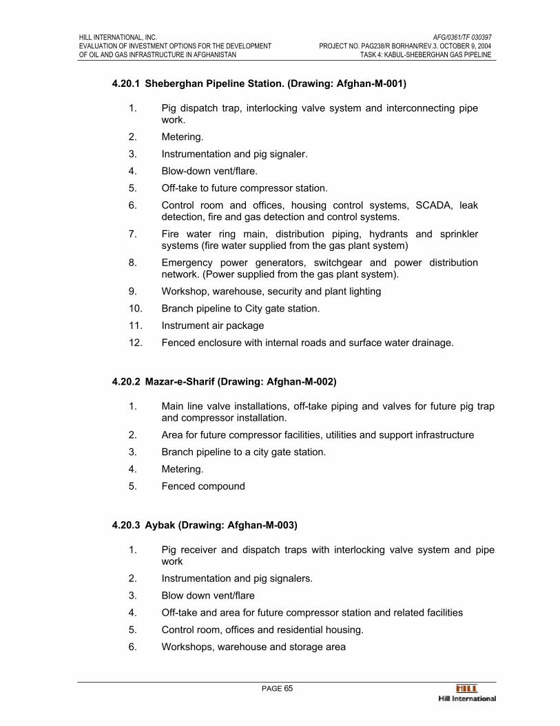
HILL INTERNATIONAL, INC. AFG/0361/TF 030397EVALUATION OF INVESTMENT OPTIONS FOR THE DEVELOPMENT PROJECT NO. PAG238/R BORHAN/REV.3. OCTOBER 9, 2004OF OIL AND GAS INFRASTRUCTURE IN AFGHANISTAN TASK 4: KABUL-SHEBERGHAN GAS PIPELINE
PAGE 65
4.20.1 Sheberghan Pipeline Station. (Drawing: Afghan-M-001)
1. Pig dispatch trap, interlocking valve system and interconnecting pipework.
2. Metering.
3. Instrumentation and pig signaler.
4. Blow-down vent/flare.
5. Off-take to future compressor station.
6. Control room and offices, housing control systems, SCADA, leakdetection, fire and gas detection and control systems.
7. Fire water ring main, distribution piping, hydrants and sprinklersystems (fire water supplied from the gas plant system)
8. Emergency power generators, switchgear and power distributionnetwork. (Power supplied from the gas plant system).
9. Workshop, warehouse, security and plant lighting
10. Branch pipeline to City gate station.
11. Instrument air package
12. Fenced enclosure with internal roads and surface water drainage.
4.20.2 Mazar-e-Sharif (Drawing: Afghan-M-002)
1. Main line valve installations, off-take piping and valves for future pig trapand compressor installation.
2. Area for future compressor facilities, utilities and support infrastructure
3. Branch pipeline to a city gate station.
4. Metering.
5. Fenced compound
4.20.3 Aybak (Drawing: Afghan-M-003)
1. Pig receiver and dispatch traps with interlocking valve system and pipework
2. Instrumentation and pig signalers.
3. Blow down vent/flare
4. Off-take and area for future compressor station and related facilities
5. Control room, offices and residential housing.
6. Workshops, warehouse and storage area
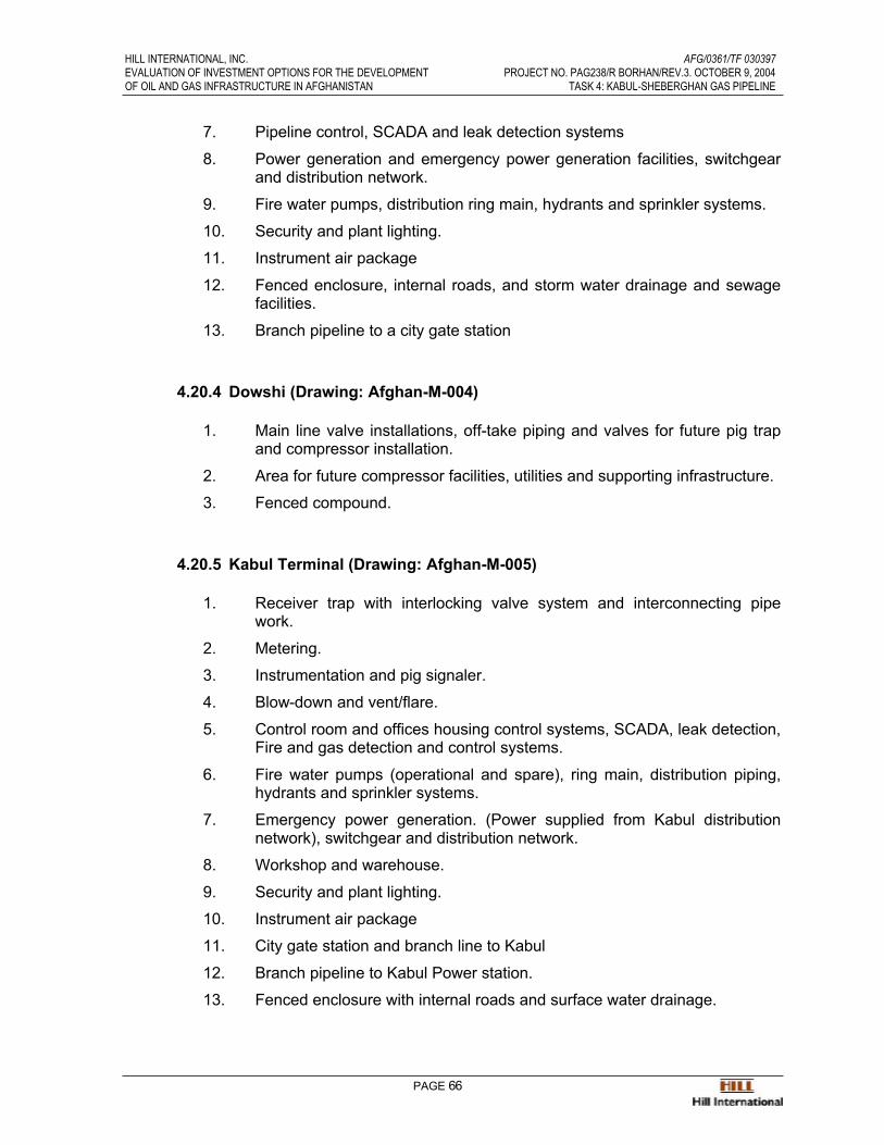
HILL INTERNATIONAL, INC. AFG/0361/TF 030397EVALUATION OF INVESTMENT OPTIONS FOR THE DEVELOPMENT PROJECT NO. PAG238/R BORHAN/REV.3. OCTOBER 9, 2004OF OIL AND GAS INFRASTRUCTURE IN AFGHANISTAN TASK 4: KABUL-SHEBERGHAN GAS PIPELINE
PAGE 66
7. Pipeline control, SCADA and leak detection systems
8. Power generation and emergency power generation facilities, switchgearand distribution network.
9. Fire water pumps, distribution ring main, hydrants and sprinkler systems.
10. Security and plant lighting.
11. Instrument air package
12. Fenced enclosure, internal roads, and storm water drainage and sewagefacilities.
13. Branch pipeline to a city gate station
4.20.4 Dowshi (Drawing: Afghan-M-004)
1. Main line valve installations, off-take piping and valves for future pig trapand compressor installation.
2. Area for future compressor facilities, utilities and supporting infrastructure.
3. Fenced compound.
4.20.5 Kabul Terminal (Drawing: Afghan-M-005)
1. Receiver trap with interlocking valve system and interconnecting pipework.
2. Metering.
3. Instrumentation and pig signaler.
4. Blow-down and vent/flare.
5. Control room and offices housing control systems, SCADA, leak detection, Fire and gas detection and control systems.
6. Fire water pumps (operational and spare), ring main, distribution piping,hydrants and sprinkler systems.
7. Emergency power generation. (Power supplied from Kabul distributionnetwork), switchgear and distribution network.
8. Workshop and warehouse.
9. Security and plant lighting.
10. Instrument air package
11. City gate station and branch line to Kabul
12. Branch pipeline to Kabul Power station.
13. Fenced enclosure with internal roads and surface water drainage.
HILL INTERNATIONAL, INC. AFG/0361/TF 030397EVALUATION OF INVESTMENT OPTIONS FOR THE DEVELOPMENT PROJECT NO. PAG238/R BORHAN/REV.3. OCTOBER 9, 2004OF OIL AND GAS INFRASTRUCTURE IN AFGHANISTAN TASK 4: KABUL-SHEBERGHAN GAS PIPELINE
PAGE 67
4.20.6 City gate station, housing pressure reduction, heating and metering
1. Blow-down vent/flare.
2. Security and plant lighting
3. Fenced enclosure
4. Fire and gas detection and control and fire-water facilities are supplied bythe Power Station.
4.21 Fire and Gas Detection and Control and Firewater Systems
The Fire and Gas (F&G) detection and control systems for Sheberghan, Aybak and Kabulwill be based on a dual redundant PLC configuration powered from the station UPS systemand comprise the following:
Gas detectors are installed at strategic locations throughout the station site, to initiate analarm (visual and audible) at the F&G panel when gas is detected at 25% Lower ExplosiveLimit (LEL) and to initiate an Emergency Shut-Down (ESD) and the closure of main pipelineblock valves into and out of the station, at 75% LEL gas detection.
Ultra-Violet (U.V.) fire detectors are installed at strategic locations throughout the station site, to initiate an alarm (visual and audible) at the F&G panel on a single detector tripping and, on co-incidence detection (two out of any two or more U.V. detectors), initiate an ESD andclosure of the main pipeline block valves into and out of the station.
Smoke Detectors are installed in the offices. An ESD at the Sheberghan pipeline station willtransmit a signal to the gas process plant control system for further action
A buried fire-water ring main is installed around the station site. The ring main is suppliedfrom a fire water tank and is pressurized by a jockey pump and supplies fire hydrants andsprinkler systems where installed. When a hydrant valve is opened or the sprinkler system is activated, the drop in the ring main pressure initiates and alarm on the Fire and Gas controlpanel (visual and audible), starts-up the firewater pumps and initiates an ESD and theclosure of the main pipeline isolation valves into and out of the Stations.
Firewater for the Sheberghan pipeline station is supplied by the gas processing plant system
Alarms and control actions at each station are managed by the local F&G control system andthe signals are routed into the main process control and SCADA systems. Facilities areprovided on the F&G and SCADA systems control panels to allow the output signals to beisolated for routine testing without initiating any output signals.
Manual, break-glass, alarm points are installed at strategic locations to allow the initiation ofan ESD.
Portable fire extinguishers are located throughout each station site.
HILL INTERNATIONAL, INC. AFG/0361/TF 030397EVALUATION OF INVESTMENT OPTIONS FOR THE DEVELOPMENT PROJECT NO. PAG238/R BORHAN/REV.3. OCTOBER 9, 2004OF OIL AND GAS INFRASTRUCTURE IN AFGHANISTAN TASK 4: KABUL-SHEBERGHAN GAS PIPELINE
PAGE 68
4.22 Branch-line Connections and City-gate Stations
Small diameter, buried pipelines supply gas from the main pipeline to city gate stations at the outskirts of the following towns:
• Km. 0 to Sheberghan (approx. 10 Km.).
• Km. 140 to Mazar-E-Sharif (approx 2 Km.).
• Km. 183 to Kholm (approx ½ Km.).
• Km. 248 to Kunduz (approx. 50Km.).
• Km. 295 to Baghlan (approx.1 Km.).
• Km. 469 to Baghram (approx 10Km.).
• Km. 508 to Kabul Power Station and Kabul city.
City gate stations comprise secure buildings containing metering, pressure reduction, gasheating, odorizing and sampling equipment/instrumentation. Data collection is through thefiber optic cable system. Power is supplied by town systems backed-up by solar powerpanels mounted on the roof feeding long life NiCad storage batteries in the building.
Gas, U.V detectors and local F&G panels are installed inside the building and are controlledby local F&G panels. Gas or fire detection initiates a closure of inlet valves into the buildingand alarms through the Fiber-optic cable to the appropriate main line station control room.
City gate stations may be unmanned.
From the city gate stations gas is distributed into the towns through buried, low pressure,high density polyethylene or similar, approved plastic pipe systems to each meteredconsumer location.
4.23 Cathodic Protection
Corrosion protection (CP) surveys will be undertaken during the pipeline survey to measurethe extent and corrosive nature of the terrain through which the pipeline is laid.
Based on the survey results and subsequent engineering, the system may comprise animpressed current system from CP stations located at 50Km. intervals. The stations adjacent to the ends of the pipeline and at locations where power is available will be powered bymains electricity. Other stations will be powered by solar panels
The buried pipeline will be insulated from above ground installations by monolithic insulation flanges and fitted with over-voltage protection to prevent damage caused by high voltage inthe line as a result of lightning strikes or other fault conditions.
CP test posts for the evaluation of CP potentials will be installed at regular intervals along the pipeline and at road and river crossings, insulation joints and CP station drain points.
HILL INTERNATIONAL, INC. AFG/0361/TF 030397EVALUATION OF INVESTMENT OPTIONS FOR THE DEVELOPMENT PROJECT NO. PAG238/R BORHAN/REV.3. OCTOBER 9, 2004OF OIL AND GAS INFRASTRUCTURE IN AFGHANISTAN TASK 4: KABUL-SHEBERGHAN GAS PIPELINE
PAGE 69
Corrosion monitoring probes and corrosion inhibitor injection facilities will be installed in thepipeline at the inlet to the Sheberghan station to monitor corrosion in the pipeline resultingfrom of a malfunction of the gas treatment plant and to inject corrosion inhibitor into thepipeline.
Until such time as construction is completed and the permanent CP system is installed andcommissioned and, depending on the soil resistivity, it may be necessary to providetemporary protection facilities. Temporary protection will be provided by the installation ofpackaged magnesium anodes in sufficient quantities to obtain protective potentialsthroughout the continuously welded section.
4.24 SCADA and Fiber-optic Cable Systems.
4.24.1 SCADA System
The pipeline, block valve installations, CP stations, Fiber-optic repeater stations,compressor stations, branch lines and city gate stations are monitored and controlled by a state of the art SCADA (Supervisory Control and Data Acquisition System). Themaster terminal unit is located in the Sheberghan pipeline control room withsubsidiary units at Aybak and Kabul stations. ESD and F&G detection systems forman integral part of the overall control system.
The control systems at each station site include:
• Field Instruments.
• Analyzers and actuators
• Controllers.
• Telecommunications.
• SCADA
• Emergency Shutdown Systems
• Fire and Gas Detection and Control Systems
4.24.2 Fiber-optic Cable System
A single mode fiber- optic cable will be connected to the SCADA system at theSheberghan pipeline control room via an electronic gateway and communicate withAybak and Kabul stations, city gate stations and pipeline block valves. Provision isincluded for interconnecting future stations.
The fiber-optic cable will be laid in the trench above the pipeline and marked with aplastic warning tape. Each length of cable (approx 4/5 Km,) is field spliced andconnected into repeater stations and terminals. The cable comprises a specified

HILL INTERNATIONAL, INC. AFG/0361/TF 030397EVALUATION OF INVESTMENT OPTIONS FOR THE DEVELOPMENT PROJECT NO. PAG238/R BORHAN/REV.3. OCTOBER 9, 2004OF OIL AND GAS INFRASTRUCTURE IN AFGHANISTAN TASK 4: KABUL-SHEBERGHAN GAS PIPELINE
PAGE 70
number of single mode optical fibers housed in loose tubes filled with a waterblocking compound, in an armored cable.
Due to range limitations of the fiber-optic transmission system, a signal booster isrequired at intermediate locations along the pipeline route. (approx. 100 Km.Intervals), and where possible and for ease of access/maintenance these stations are combined with block valve and CP station locations.
The repeater stations will be housed in partially buried, concrete structures andcomprise batteries, cabinet-housed transmission equipment and the fiber-optic cableterminations. A solar array is mounted on the top of the repeater station enclosure toprovide power for the signal boosters. The installation will be security fenced.
The fiber-optic system will be used primarily for control of pipeline systems and voice communications. Line capacity may allow for a secondary use of the fiber-optic cable system to be used for telecommunications services between the towns along thepipeline alignment.
4.25 Right-of-Way (ROW) Reinstatement
On completion of construction and testing of the pipeline, ROW and land used for pipelineconstruction and installation will be reinstated to an acceptable condition. Roads, crossingtracks, irrigation channels, bridges and landowners fences will be repaired or replaced andbrought back into operational service.
All waste construction debris will be collected and returned to the contractor’s warehouse forsafe disposal.
In Section II the ROW will be reinstated to prevent erosion resulting from the creation of new watercourses and access roads will be up-graded to facilitate operational inspection andmaintenance activities.
It is not anticipated that the pipeline will be constructed through areas of woodland or forest.
4.26 As-built Surveys
An ‘as-built’ survey will be undertaken by the turnkey pipeline contractor on completion of allconstruction activities. Route survey drawings will be produced, to an acceptable scale, toinclude pipeline alignment and profiles and details such as pipe identification numbers andlengths, locations of block and isolation valves, hydrostatic test data, CP stations and testpoints, fiber-optic repeater stations and cable splice locations, road, track, river and irrigationchannel crossings, take off points for branch pipelines and their routes to the towns beingsupplied with natural gas and city gate station locations.

HILL INTERNATIONAL, INC. AFG/0361/TF 030397EVALUATION OF INVESTMENT OPTIONS FOR THE DEVELOPMENT PROJECT NO. PAG238/R BORHAN/REV.3. OCTOBER 9, 2004OF OIL AND GAS INFRASTRUCTURE IN AFGHANISTAN TASK 4: KABUL-SHEBERGHAN GAS PIPELINE
PAGE 71
4.26.1 Line Markers
Concurrent with the as-built survey, Km. marker posts will be installed along thepipeline ROW to mark the centerline of the buried pipeline. The marker posts will bemade of pre-cast reinforced concrete and will be concreted into place on to the ROW.
All road and river crossings are similarly marked.
4.27 Testing Requirements and Procedures
During construction, 100 psi air leak tests will be undertaken on the welded sections of thepipeline before the joints are field wrapped.
Hydrostatic pressure testing the pipeline requires treated, clean water. To ensure itsavailability, it may be necessary for the contractor to sink a borehole to produce thequantities and rates of production required to fill the pipeline sections being tested.
Test water will be filtered, all debris and sand particles removed and then transferred into asteel tank for the addition of corrosion inhibitor before being used in the pipeline. The pipeline is pressure tested in sections between block valves, or if required in shorter lengths.
For the test, a rubber cupped pig will be loaded into the pipeline at a dispatcher trap andpropelled through the pipeline by a high volume/pressure hydraulic test pump. The volume of test water pumped into the pipeline is metered and recorded against the pump dischargepressure, to monitor the location of the pig in the pipeline.
When all the air in the pipeline has been expelled ahead of the pig and the pipeline is full ofwater, a high pressure plunger pump is connected to pressurize the pipeline to the testpressure required. The test pressure will be recorded on a chart pressure recorder (time vpressure) and held for a specified time (24 Hrs.) to prove pipeline structural integrity. Thetesting procedures and results will be signed off by the test engineer and witnessed by thePMT’s inspector of engineer.
In Section II, particularly where the pipeline traverses the Salang Pass, variations in elevation over short distances (2,744 meters over 60 Km. in the north and 2,243 meters over 32 Km. in the south) and static water pressures necessitate testing the pipeline in shorter lengths (5 to8Km.) to ensure the required test pressure is met without exceeding the pipe yield pressure.
The availability of the quantities and quality of test water in these areas is uncertain andrequires investigation.
Should test water be unavailable, a possible alternative to field hydraulic testing is to yieldtest each pipe joint in the pipe mill to ensure the structural integrity and subject each field toa 100% radiographic inspection.
An evaluation of the test options will be made when an accurate pipeline route profile hasbeen produced and the requirements for multiple testing of short sections of pipeline and the availability of test water has been established.

HILL INTERNATIONAL, INC. AFG/0361/TF 030397EVALUATION OF INVESTMENT OPTIONS FOR THE DEVELOPMENT PROJECT NO. PAG238/R BORHAN/REV.3. OCTOBER 9, 2004OF OIL AND GAS INFRASTRUCTURE IN AFGHANISTAN TASK 4: KABUL-SHEBERGHAN GAS PIPELINE
PAGE 72
All tie-in welds for test sections will be subjected to 100% radiographic inspection.
4.28 Pipeline Cleaning and Gauging
Upon completion of each section of the pipeline between block valves or scraper trapinstallations and following the completion of the hydrostatic pressure test, rubber cuppedcleaning pigs are run through the pipeline to clear out test water.
Following this, a gauging pig is passed through the pipeline to detect ovality, dents, bucklesor pipe joint weld metal penetration likely to impede the progress of or damage an intelligent pig. The gauging pig is fitted with a light metal disc which deforms or tears as it passesthrough the pipeline to indicate the presence of internal protrusions and/or pipe deformity.
4.29 Gas Introduction
The pipeline between the pig traps at each station, (Sheberghan – Aybak and Aybak –Kabul) will be dried out before the introduction of natural gas is commenced.
At the Sheberghan station pig dispatch trap a nitrogen slug will be introduced into thepipeline behind a rubber-cupped pig or sphere, followed by natural gas from the gas processplant. At the Aybak station receiver pig trap displaced air will be bled off through the blow-down piping system.
When the pig ( and the nitrogen slug) is be detected by the pig signaler on entry into theAybak pig receiver trap, the nitrogen slug will be diverted into the by-pass line, a pig will belaunched from the dispatch trap and the filling operation repeated in the section from Aybakstation to Kabul station.
At all stages of this operation the location of the pig and the nitrogen/air interface will bemonitored and recorded, as the rate of the filling operation is controlled by the volume andpressure of natural gas being metered into the pipeline at Sheberghan and the back pressure inside the pipeline controlled by the blow down piping system at the receiver traps. The gasfilling operation must be continuous
The nitrogen slug can be vented to atmosphere at the Kabul station pig receiver trap.
Instrumentation will be installed in the pig trap blow down piping system to monitor andanalyze the composition of the air/nitrogen/natural gas mixture to ensure that the pipeline is free of potentially dangerous concentrations.
On completion of the gas filling operation, an intelligent pig will be run between station pigtraps, to measure and record the structural condition of the pipeline to be used as a benchmark for future intelligent pig inspections.

HILL INTERNATIONAL, INC. AFG/0361/TF 030397EVALUATION OF INVESTMENT OPTIONS FOR THE DEVELOPMENT PROJECT NO. PAG238/R BORHAN/REV.3. OCTOBER 9, 2004OF OIL AND GAS INFRASTRUCTURE IN AFGHANISTAN TASK 4: KABUL-SHEBERGHAN GAS PIPELINE
PAGE 73
4.30 Project Documentation
Records and as-built drawings and documentation together with test records, operational and maintenance documentation is, on completion of the construction contract, formally handedover by the turn-key construction contractor to the PMT. This comprises the following
• Pipe mill metallurgical and pressure tests.
• Factory applied P.E. coating inspection.
• Shipment inspection.
• Pipeline equipment manufacturer’s certification, pressure tests, drawingsand documents. (valves, pipe fittings, pig trap assemblies, interconnectingpipe work, instrumentation, control systems, fiber-optic cable and systems, cathodic protection materials and systems, metering equipment etc.,).
• Field weld ultrasonic and radiographic test documentation
• Pipeline system hydrostatic test reports,
• Gauging pig test reports
• Pipeline system as-built drawings. (Pipeline alignment, elevations, valve,cathodic protection repeater stations and ground beds, fiber-optic cablesplices and repeater stations
• SCADA and Leak detection and control systems documentation
• Maintenance and operations manuals.
• Spares provisioning lists.
On acceptance of the pipeline systems completed by the turn-key contractor, the PMT shallarchive all related documentation for operational control and reference purposes and formthe basis for the PMT to prepare the requirements for the establishment of resources andprograms for operational and maintenance activities.
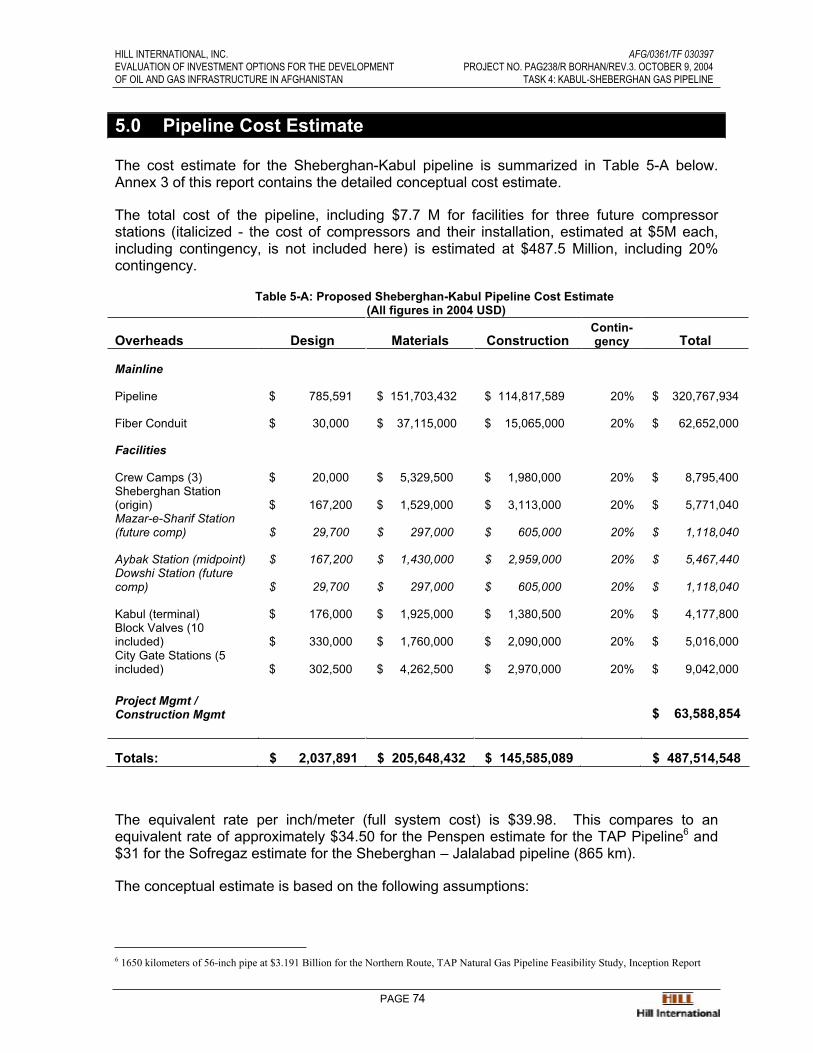
HILL INTERNATIONAL, INC. AFG/0361/TF 030397EVALUATION OF INVESTMENT OPTIONS FOR THE DEVELOPMENT PROJECT NO. PAG238/R BORHAN/REV.3. OCTOBER 9, 2004OF OIL AND GAS INFRASTRUCTURE IN AFGHANISTAN TASK 4: KABUL-SHEBERGHAN GAS PIPELINE
PAGE 74
5.0 Pipeline Cost Estimate
The cost estimate for the Sheberghan-Kabul pipeline is summarized in Table 5-A below.Annex 3 of this report contains the detailed conceptual cost estimate.
The total cost of the pipeline, including $7.7 M for facilities for three future compressorstations (italicized - the cost of compressors and their installation, estimated at $5M each,including contingency, is not included here) is estimated at $487.5 Million, including 20%contingency.
Table 5-A: Proposed Sheberghan-Kabul Pipeline Cost Estimate (All figures in 2004 USD)
Overheads Design Materials ConstructionContin-gency Total
Mainline
Pipeline $ 785,591 $ 151,703,432 $ 114,817,589 20% $ 320,767,934
Fiber Conduit $ 30,000 $ 37,115,000 $ 15,065,000 20% $ 62,652,000
Facilities
Crew Camps (3) $ 20,000 $ 5,329,500 $ 1,980,000 20% $ 8,795,400 Sheberghan Station (origin) $ 167,200 $ 1,529,000 $ 3,113,000 20% $ 5,771,040 Mazar-e-Sharif Station (future comp) $ 29,700 $ 297,000 $ 605,000 20% $ 1,118,040
Aybak Station (midpoint) $ 167,200 $ 1,430,000 $ 2,959,000 20% $ 5,467,440 Dowshi Station (future comp) $ 29,700 $ 297,000 $ 605,000 20% $ 1,118,040
Kabul (terminal) $ 176,000 $ 1,925,000 $ 1,380,500 20% $ 4,177,800 Block Valves (10 included) $ 330,000 $ 1,760,000 $ 2,090,000 20% $ 5,016,000 City Gate Stations (5 included) $ 302,500 $ 4,262,500 $ 2,970,000 20% $ 9,042,000
Project Mgmt / Construction Mgmt $ 63,588,854
Totals: $ 2,037,891 $ 205,648,432 $ 145,585,089 $ 487,514,548
The equivalent rate per inch/meter (full system cost) is $39.98. This compares to anequivalent rate of approximately $34.50 for the Penspen estimate for the TAP Pipeline6 and$31 for the Sofregaz estimate for the Sheberghan – Jalalabad pipeline (865 km).
The conceptual estimate is based on the following assumptions:
6 1650 kilometers of 56-inch pipe at $3.191 Billion for the Northern Route, TAP Natural Gas Pipeline Feasibility Study, Inception Report

HILL INTERNATIONAL, INC. AFG/0361/TF 030397EVALUATION OF INVESTMENT OPTIONS FOR THE DEVELOPMENT PROJECT NO. PAG238/R BORHAN/REV.3. OCTOBER 9, 2004OF OIL AND GAS INFRASTRUCTURE IN AFGHANISTAN TASK 4: KABUL-SHEBERGHAN GAS PIPELINE
PAGE 75
Line Pipe
The following table shows the line pipe quantities and pricing used under different terrainconditions.
Table 5-B: Line Pipe Pricing
Terrain/Description MetersTotal Cost excluding
Contingency Cost/MeterCross Country - Agricultural 126,000 $ 57,129,923 $453.41 Cross Country - Desert 176,000 $ 79,800,527 $453.41 Cross Country -Mountainous (Light) 153,000 $ 71,881,892 $469.82 Cross Country - Mountainous (Heavy) 50,000 $ 26,771,654 $535.43 Blasting 80,000 $ 25,498,688 $318.73 Bores 3,000 $ 4,759,843 $1,586.61
Pricing
All pricing is assumed to be 2004 USD, built in Afghanistan. No escalation has beenincluded in the estimates.
Contingencies and Markups
Project Contingency is taken at 20%. All Construction estimates also include a 10%contractor’s markup figure. Contingency is intended to cover unforeseen conditions, risks,currency fluctuations, escalation, schedule slippage, and cost overruns.
Block Valves
Ten block valves have been included in the estimate
Compressor Stations
The cost of the facilities for all three future compression stations has been included in theestimate. The cost of the 5 MW compressors and their installation has not been included in the base estimate, although they have been factored into the NPV and IRR calculations.Each 5 MW compressor is estimated at $5 M including delivery and installation.
Major Crossings and Tunnels
No major river or railroad crossings or tunnels are anticipated.
Construction Costs
Construction costs include ROW surveying and preparation, crossings, trenching, pipelaying,backfill and cover, installation and erection of facilities, and testing
Material Costs
Material Costs include fabrication and delivery.

HILL INTERNATIONAL, INC. AFG/0361/TF 030397EVALUATION OF INVESTMENT OPTIONS FOR THE DEVELOPMENT PROJECT NO. PAG238/R BORHAN/REV.3. OCTOBER 9, 2004OF OIL AND GAS INFRASTRUCTURE IN AFGHANISTAN TASK 4: KABUL-SHEBERGHAN GAS PIPELINE
PAGE 76
6.0 Project Schedule
6.1 Project Development Requirements
In developing the infrastructure for the construction and operation of a natural gas pipelineand related distribution systems in Afghanistan, it is essential to plan and manage all phases carefully to create a well-structured, operational organization for the timely and economiccompletion of the project construction phase and the management of continuing day-to-dayoperational activities.
This necessitates early creation of a well structured project development strategy by a multi-national, Project Management Team (PMT) and the subsequent appointment of consultants,to assist with the preparation of preliminary engineering investigations and inquirydocuments, following which it will be possible to proceed with the selection of a turn-keyconstruction contractor to undertake detailed engineering, material and equipmentprocurement and construction.
The first task for the PMT, with assistance from its consultants, will be to prepare a detailedcost estimate and program of work for approval by the Government and Funding agencies.
The PMT could take 6-9 months to become fully established and operational. It should, as aminimum, comprise the following in-country key personnel and facilities:
• Project Manager
• Deputy Project Manager
• Lawyer and Advisor
• Government liaison officer; (customs, roads, communications, securityetc.)
• Right-of-way and land acquisition officer
• Contracts Engineer and Administrator
• QA/QC Engineer
• Planning Engineer
• Cost control Engineer/Accountant
• Pipeline Engineer
• Mechanical Engineer
• Civil Engineer
• Electrical Engineer
• Instrument and Control Engineer
• Secretaries and Office Personnel
HILL INTERNATIONAL, INC. AFG/0361/TF 030397EVALUATION OF INVESTMENT OPTIONS FOR THE DEVELOPMENT PROJECT NO. PAG238/R BORHAN/REV.3. OCTOBER 9, 2004OF OIL AND GAS INFRASTRUCTURE IN AFGHANISTAN TASK 4: KABUL-SHEBERGHAN GAS PIPELINE
PAGE 77
• Offices and support facilities
The establishment of the PMT, appointment of consultants, the completion of preliminaryengineering studies, pipeline route location, placing of orders for long delivery items ofmaterial and equipment should be commenced as soon as the resources are available, toallow the establishment of a viable project program.
Consultants will be required to support the PMT and to provide temporary engineering andrelated personnel to fill vacant positions and to undertake the specialist studies that will berequired.
The selection of a turnkey construction contractor should be by competitive tendering frompre-qualified, international construction contractors with proven experience of detailedengineering design, pipeline materials and equipment procurement, inspection, logisticsmanagement and pipeline project construction activities.
The turnkey contractor will establish design and project management facilities in Kabul andconstruction camps and related facilities at strategic locations along the pipeline route.
It is assumed that the security situation in Afghanistan will have improved by the time thepipeline construction is to commence. It is recommended, however, that security for theproject be subcontracted by the general contractor to a specialized security firm.
6.2 Construction Program
As there is no international, turnkey pipeline construction contractors currently working inAfghanistan, all construction and related equipment, services and support facilities must beimported. Mobilization by the selected contractor may take up to 6 months beforeconstruction activities could start.
6.2.1 Sections I & III (380 Km.)
Using two/three pipeline spreads for construction, the pipeline can be constructed ata rate of approximately 2 Km. per day per spread, in normal terrain. If rock or sub-surface rock is present and it can be ripped before being excavated, then thisprogress can be maintained. Should rocky terrain be encountered which cannot beripped, drilling and blasting will be required for the ROW and trenching, and will slowdown progress. This can be accelerated by the use of additional construction teamsand equipment.
6.2.2 Section II (130 Km.)
Conventional pipeline spread construction techniques cannot be used in this section.The more difficult terrain will require the construction of a ROW which is adequatelysized for access by construction equipment and the excavation of the trench, both ofwhich are likely to be through steep sided, rocky terrain.
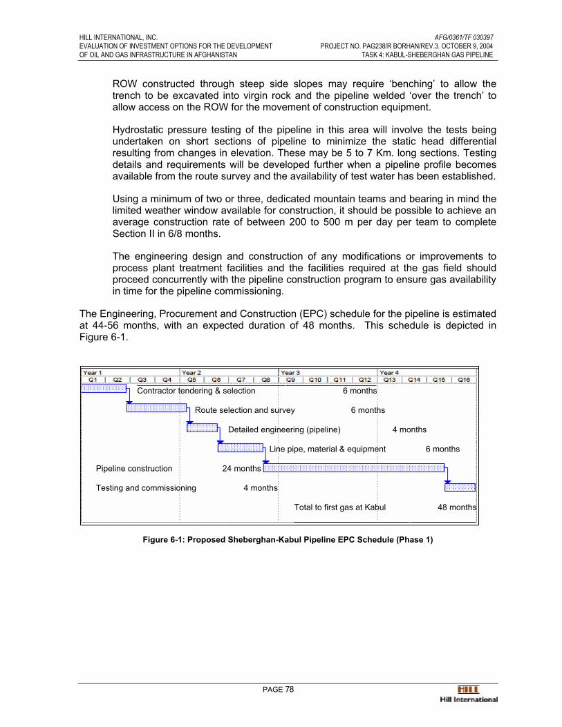
HILL INTERNATIONAL, INC. AFG/0361/TF 030397EVALUATION OF INVESTMENT OPTIONS FOR THE DEVELOPMENT PROJECT NO. PAG238/R BORHAN/REV.3. OCTOBER 9, 2004OF OIL AND GAS INFRASTRUCTURE IN AFGHANISTAN TASK 4: KABUL-SHEBERGHAN GAS PIPELINE
PAGE 78
ROW constructed through steep side slopes may require ‘benching’ to allow thetrench to be excavated into virgin rock and the pipeline welded ‘over the trench’ toallow access on the ROW for the movement of construction equipment.
Hydrostatic pressure testing of the pipeline in this area will involve the tests beingundertaken on short sections of pipeline to minimize the static head differentialresulting from changes in elevation. These may be 5 to 7 Km. long sections. Testingdetails and requirements will be developed further when a pipeline profile becomesavailable from the route survey and the availability of test water has been established.
Using a minimum of two or three, dedicated mountain teams and bearing in mind thelimited weather window available for construction, it should be possible to achieve an average construction rate of between 200 to 500 m per day per team to completeSection II in 6/8 months.
The engineering design and construction of any modifications or improvements toprocess plant treatment facilities and the facilities required at the gas field shouldproceed concurrently with the pipeline construction program to ensure gas availability in time for the pipeline commissioning.
The Engineering, Procurement and Construction (EPC) schedule for the pipeline is estimated at 44-56 months, with an expected duration of 48 months. This schedule is depicted inFigure 6-1.
Contractor tendering & selection 6 months
Route selection and survey 6 months
Detailed engineering (pipeline) 4 months
Line pipe, material & equipment 6 months
Pipeline construction 24 months
Testing and commissioning 4 months
Total to first gas at Kabul 48 months
Figure 6-1: Proposed Sheberghan-Kabul Pipeline EPC Schedule (Phase 1)
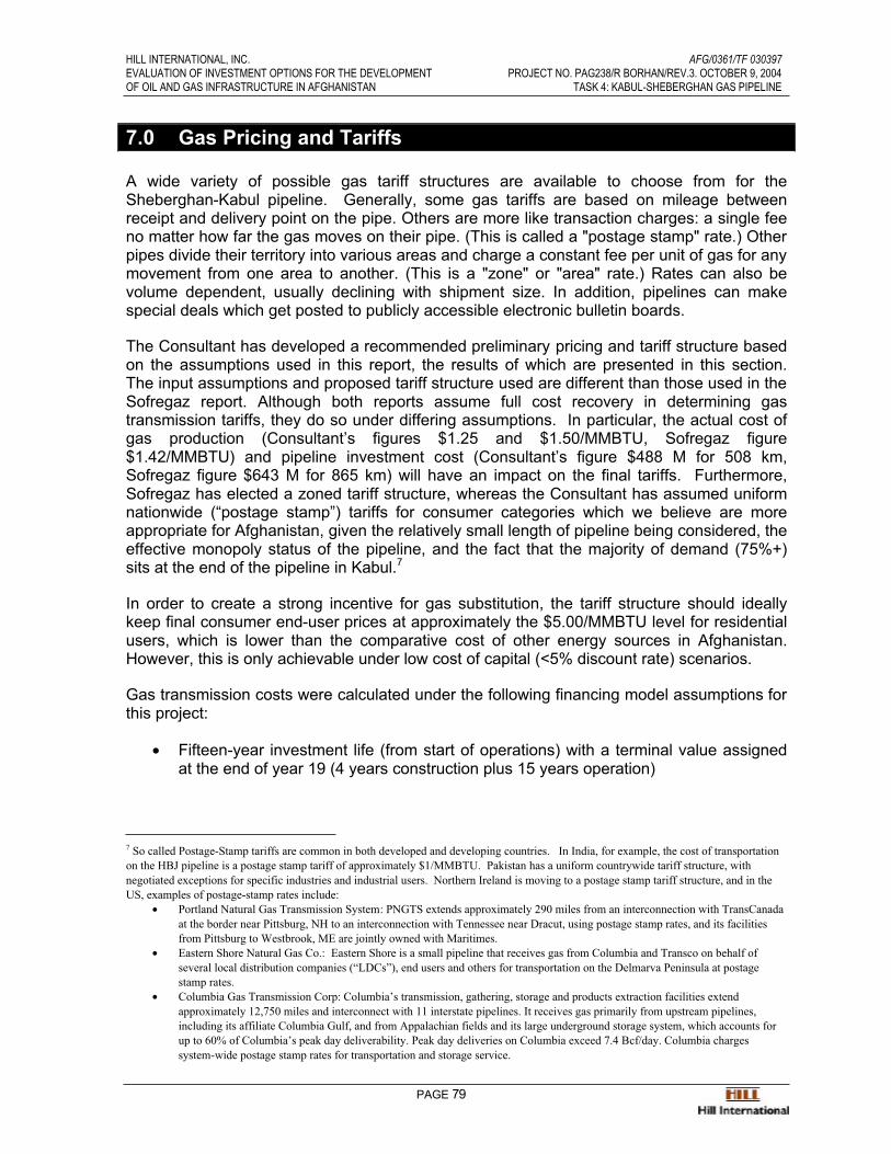
HILL INTERNATIONAL, INC. AFG/0361/TF 030397EVALUATION OF INVESTMENT OPTIONS FOR THE DEVELOPMENT PROJECT NO. PAG238/R BORHAN/REV.3. OCTOBER 9, 2004OF OIL AND GAS INFRASTRUCTURE IN AFGHANISTAN TASK 4: KABUL-SHEBERGHAN GAS PIPELINE
PAGE 79
7.0 Gas Pricing and Tariffs
A wide variety of possible gas tariff structures are available to choose from for theSheberghan-Kabul pipeline. Generally, some gas tariffs are based on mileage betweenreceipt and delivery point on the pipe. Others are more like transaction charges: a single feeno matter how far the gas moves on their pipe. (This is called a "postage stamp" rate.) Other pipes divide their territory into various areas and charge a constant fee per unit of gas for any movement from one area to another. (This is a "zone" or "area" rate.) Rates can also bevolume dependent, usually declining with shipment size. In addition, pipelines can makespecial deals which get posted to publicly accessible electronic bulletin boards.
The Consultant has developed a recommended preliminary pricing and tariff structure basedon the assumptions used in this report, the results of which are presented in this section.The input assumptions and proposed tariff structure used are different than those used in the Sofregaz report. Although both reports assume full cost recovery in determining gastransmission tariffs, they do so under differing assumptions. In particular, the actual cost ofgas production (Consultant’s figures $1.25 and $1.50/MMBTU, Sofregaz figure$1.42/MMBTU) and pipeline investment cost (Consultant’s figure $488 M for 508 km,Sofregaz figure $643 M for 865 km) will have an impact on the final tariffs. Furthermore,Sofregaz has elected a zoned tariff structure, whereas the Consultant has assumed uniformnationwide (“postage stamp”) tariffs for consumer categories which we believe are moreappropriate for Afghanistan, given the relatively small length of pipeline being considered, theeffective monopoly status of the pipeline, and the fact that the majority of demand (75%+)sits at the end of the pipeline in Kabul.7
In order to create a strong incentive for gas substitution, the tariff structure should ideallykeep final consumer end-user prices at approximately the $5.00/MMBTU level for residentialusers, which is lower than the comparative cost of other energy sources in Afghanistan.However, this is only achievable under low cost of capital (<5% discount rate) scenarios.
Gas transmission costs were calculated under the following financing model assumptions for this project:
• Fifteen-year investment life (from start of operations) with a terminal value assignedat the end of year 19 (4 years construction plus 15 years operation)
7 So called Postage-Stamp tariffs are common in both developed and developing countries. In India, for example, the cost of transportation on the HBJ pipeline is a postage stamp tariff of approximately $1/MMBTU. Pakistan has a uniform countrywide tariff structure, with negotiated exceptions for specific industries and industrial users. Northern Ireland is moving to a postage stamp tariff structure, and in the US, examples of postage-stamp rates include:
• Portland Natural Gas Transmission System: PNGTS extends approximately 290 miles from an interconnection with TransCanada at the border near Pittsburg, NH to an interconnection with Tennessee near Dracut, using postage stamp rates, and its facilities from Pittsburg to Westbrook, ME are jointly owned with Maritimes.
• Eastern Shore Natural Gas Co.: Eastern Shore is a small pipeline that receives gas from Columbia and Transco on behalf of several local distribution companies (“LDCs”), end users and others for transportation on the Delmarva Peninsula at postage stamp rates.
• Columbia Gas Transmission Corp: Columbia’s transmission, gathering, storage and products extraction facilities extend approximately 12,750 miles and interconnect with 11 interstate pipelines. It receives gas primarily from upstream pipelines, including its affiliate Columbia Gulf, and from Appalachian fields and its large underground storage system, which accounts for up to 60% of Columbia’s peak day deliverability. Peak day deliveries on Columbia exceed 7.4 Bcf/day. Columbia charges system-wide postage stamp rates for transportation and storage service.
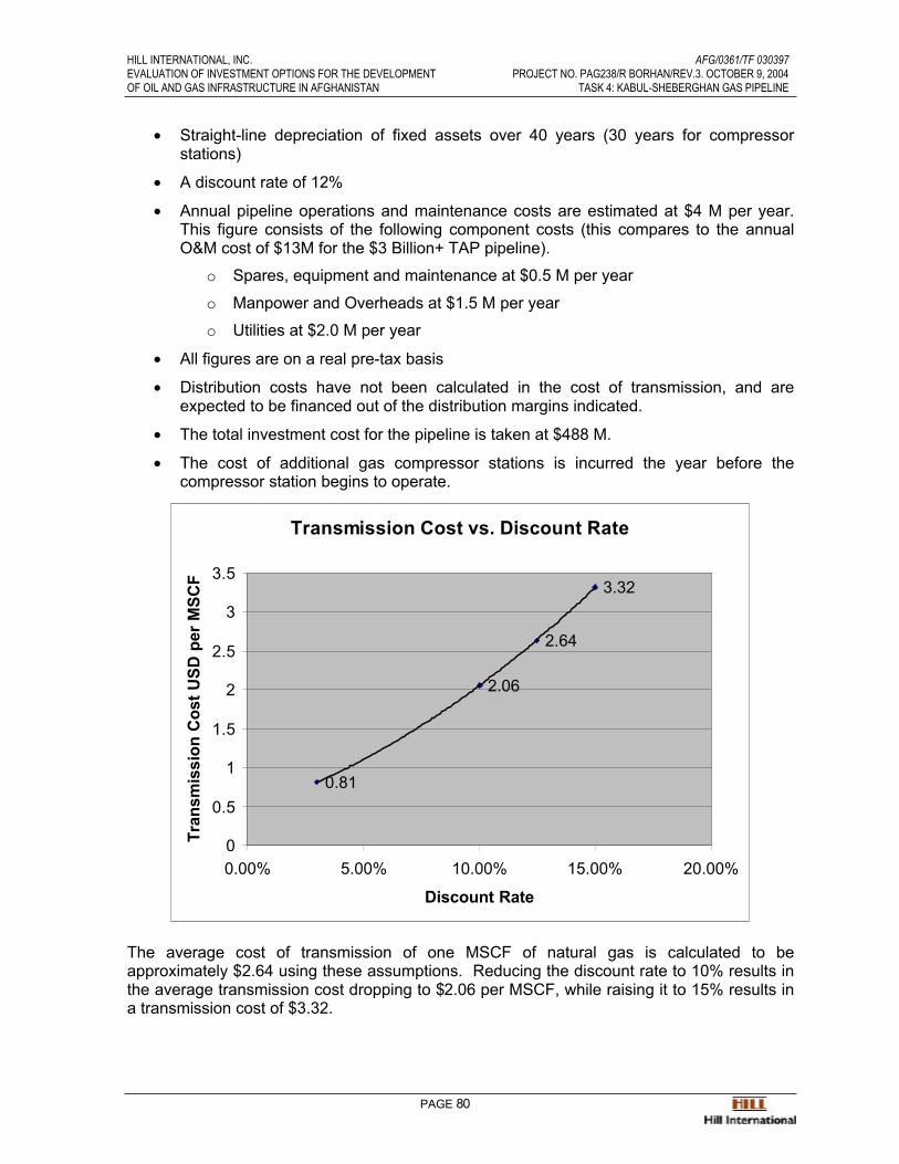
HILL INTERNATIONAL, INC. AFG/0361/TF 030397EVALUATION OF INVESTMENT OPTIONS FOR THE DEVELOPMENT PROJECT NO. PAG238/R BORHAN/REV.3. OCTOBER 9, 2004OF OIL AND GAS INFRASTRUCTURE IN AFGHANISTAN TASK 4: KABUL-SHEBERGHAN GAS PIPELINE
PAGE 80
• Straight-line depreciation of fixed assets over 40 years (30 years for compressorstations)
• A discount rate of 12%
• Annual pipeline operations and maintenance costs are estimated at $4 M per year.This figure consists of the following component costs (this compares to the annualO&M cost of $13M for the $3 Billion+ TAP pipeline).
o Spares, equipment and maintenance at $0.5 M per year
o Manpower and Overheads at $1.5 M per year
o Utilities at $2.0 M per year
• All figures are on a real pre-tax basis
• Distribution costs have not been calculated in the cost of transmission, and areexpected to be financed out of the distribution margins indicated.
• The total investment cost for the pipeline is taken at $488 M.
• The cost of additional gas compressor stations is incurred the year before thecompressor station begins to operate.
Transmission Cost vs. Discount Rate
0.81
2.06
2.64
3.32
0
0.5
1
1.5
2
2.5
3
3.5
0.00% 5.00% 10.00% 15.00% 20.00%
Discount Rate
Tran
smis
sion
Cos
t USD
per
MSC
F
The average cost of transmission of one MSCF of natural gas is calculated to beapproximately $2.64 using these assumptions. Reducing the discount rate to 10% results inthe average transmission cost dropping to $2.06 per MSCF, while raising it to 15% results ina transmission cost of $3.32.

HILL INTERNATIONAL, INC. AFG/0361/TF 030397EVALUATION OF INVESTMENT OPTIONS FOR THE DEVELOPMENT PROJECT NO. PAG238/R BORHAN/REV.3. OCTOBER 9, 2004OF OIL AND GAS INFRASTRUCTURE IN AFGHANISTAN TASK 4: KABUL-SHEBERGHAN GAS PIPELINE
PAGE 81
The following table shows two potential tariff structures which differ only in the cost ofproduction, assumed at both $1.25 and $1.50 per MSCF. Both tariff scenarios assume fullcost recovery of the pipeline construction and operation costs.
Table 7-A: Indicative “Postage Stamp” Gas Tariff Structure
Tariff Structure 1 Tariff Structure 2Cost of Production $1.25 $1.50Transmission Fee $2.64 $2.64Direct TakeOff $3.89 $4.14Distribution Margin Industrial & Power $0.50 $0.50 Commercial $2.00 $2.00 Residential $2.50 $2.50End-User Fee Industrial $4.39 $4.64 Commercial $5.89 $6.14 Residential $6.39 $6.64
The tariffs above are assumed to be fixed for the 30-year period. In reality, tariffs would besubject to increases, and would likely be set on a partly volumetric, partly capacity and partly customer basis.
Distribution costs have been assumed to be $0.50 per MSCF for Industrial and Powerconsumers and $2.00 and $2.50 per MSCF, respectively, for commercial and residentialconsumers. It is estimated that a household consuming 35 MMBTU per annum wouldcontribute approximately $87.50 (35 MMBTU x $2.50) per year to the distribution margin,which, at an average connection cost of $1,000 per household would result in a 8.75%project IRR over 30 years for the distribution sector.
As an illustrative example, neighboring Pakistan’s gas tariff structure is presented in Table 7-B below. Note that unlike the above tariffs, Pakistan’s rate structure appears to indicate aheavy level of subsidies for certain sectors. However, a subsidized gas pricing is notrecommended for Afghanistan.

HILL INTERNATIONAL, INC. AFG/0361/TF 030397EVALUATION OF INVESTMENT OPTIONS FOR THE DEVELOPMENT PROJECT NO. PAG238/R BORHAN/REV.3. OCTOBER 9, 2004OF OIL AND GAS INFRASTRUCTURE IN AFGHANISTAN TASK 4: KABUL-SHEBERGHAN GAS PIPELINE
PAGE 82
Table 7-B: Pakistan Gas Pricing Structure
USD/MMBTU
CategoryW.E.F. 26-3-2003
Rs. MMBTU (@ 54.64 Rs/USD – eff. 26-3-2003)
(A) DOMESTIC(i) upto 3.55 MCFT/MONTH 67.95 1.24 (ii) 3.55 TO 7.1 MCFT/MONTH 102.37 1.87 (iii) 7.1 TO 10.64 MCFT/MONTH 163.78 3.00 (iv) All over 10.64 MCFT/MONTH 213.06 3.90 (B) COMMERCIAL 190.02 3.48 (C) INDUSTRIAL (i) General 168.88 3.09 (ii) Cement 222.32 4.07 (D) CNG STATION 168.88 3.09 (E) FERTILIZER (ON SNGPL & SSGCL SYSTEM) (i) FOR FEED STOCK (a) Pak American Fertilizer Ltd (PAFL) 36.77 0.67 (b) FFC Jorden 36.77 0.67 (c)Dadoud / Pak Arab 62.57 1.15(d) Pak China / Hazara 66.4 1.22 (ii) FOR FUEL 168.88 3.09 (i)Daood & Pak Arab (On Mari's System) 168.88 3.09 (iii) FOR FEEK STOCK (a) Engro Chemical (New) 13.09 0.24 (b) Engro Chemical (Old) 61.68 1.13 (c) FFC (Plants) 61.68 1.13(d) Pak Saudi 61.68 1.13 (iv) FOR FUEL 168.88 3.09 (F) POWER (ON SNGPL & SSGCL SYSTEM) 168.88 3.09 (G) LIBERTY POWER LIMITED 222.89 4.08 (i) RAW GAS SOD TO WAPDA' S GUDDU POWER STATION (a) Kandkot (866 BTU) (III) MARI (754) 163.15 2.99(b) Mari (754) 158.68 2.90 (c) Sara Suri Fields 158.68 2.90
Source: Pakistan Ministry of Petroleum and Natural Resources, http://www.pakistan.gov.pk/petroleum-division/infoservices

HILL INTERNATIONAL, INC. AFG/0361/TF 030397EVALUATION OF INVESTMENT OPTIONS FOR THE DEVELOPMENT PROJECT NO. PAG238/R BORHAN/REV.3. OCTOBER 9, 2004OF OIL AND GAS INFRASTRUCTURE IN AFGHANISTAN TASK 4: KABUL-SHEBERGHAN GAS PIPELINE
PAGE 83
8.0 Financing Options
Financing options for infrastructure projects in Afghanistan’s energy sector have beendiscussed in a number of other reports, particularly the Norconsult and Sofregaz reports,where efforts have been made to identify potential sources of funding for energy sectorinvestments. As noted in the previous work, almost all of the committed funding forreconstruction in the country to date has a specific humanitarian purpose. Investments inenergy infrastructure, identified in the current report as well as in other studies, remainlargely unimplemented.
To avoid repetition, the Consultant is not repeating the background information on potentialsources of financing in this report. Annex 4 of this report includes relevant excerpts from theSofregaz report on this subject.
With regard to financing a large capital-intensive project such as the Sheberghan-Kabulpipeline, the following issues need to be considered in recommending whether private sector participation in the sector is realistic:
• Large volumes of public funds are unlikely to be available over the long termfor Afghanistan’s energy infrastructure needs;
• Operating subsidies for energy companies are beyond the fiscal ability of thecentral government;
• Accessibility and utilization of funds from bilateral and multilateral sources aredoubtful for this type of investment in Afghanistan at this stage of itsdevelopment;
• Local funding is limited and can play a role primarily in civil works and otherlabor intensive phases of each investment; and
• Commercial banks, private investors and export credit agencies will notbecome major players in the energy sector until infrastructure improvement isunder way.
The Consultant believes that there are limited short or medium-term opportunities for privatesector participation in large infrastructure projects, particularly a $500 M pipeline project.Lack of gas sector development, an uncertain regulatory and institutional framework, political risk and security concerns, uncertainly over Afghanistan’s sustainability, combined with thelack of recent data on gas reserves and production potential implies that initial infrastructureinvestments will have to be made with donor funding until the political and investment climate is improved enough to attract private sector investment.
Indeed the economic analyses leading to the indicative tariff structure presented in Section7.0 of this report show that under commercial terms, the cost of gas transmission risessubstantially, likely placing gas outside the reach of Kabul customers, the primary demandsource for gas conversion.
Based on the current economic, political and security climate in Afghanistan, coupled withlimited knowledge of the available gas reserves and uncertain regulatory and institutionalframework, the Consultant therefore concludes that the Sheberghan-Kabul pipeline beconsidered as a long-term investment option in the development of Afghanistan’s oil and gas

HILL INTERNATIONAL, INC. AFG/0361/TF 030397EVALUATION OF INVESTMENT OPTIONS FOR THE DEVELOPMENT PROJECT NO. PAG238/R BORHAN/REV.3. OCTOBER 9, 2004OF OIL AND GAS INFRASTRUCTURE IN AFGHANISTAN TASK 4: KABUL-SHEBERGHAN GAS PIPELINE
PAGE 84
sector and power supply scenarios for Kabul, and that the economics of the pipeline be re-evaluated after 4-5 years (2010) when the status of gas availability and the powerdevelopment program for Kabul are better defined.

HILL INTERNATIONAL, INC. AFG/0361/TF 030397EVALUATION OF INVESTMENT OPTIONS FOR THE DEVELOPMENT PROJECT NO. PAG238/R BORHAN/REV.3. OCTOBER 9, 2004OF OIL AND GAS INFRASTRUCTURE IN AFGHANISTAN TASK 4: KABUL-SHEBERGHAN GAS PIPELINE
PAGE 85
9.0 Gas Versus Power Transmission
In examining the trade-off between transmitting gas versus electricity to Kabul, it is evidentthat any incremental power generation that can be transmitted through existing transmissionlines (or planned/ongoing transmission capacity increases to existing lines) will result incheaper delivered energy to Kabul. This existing capacity is estimated by Norconsult in thePower Sector Master Plan to be approximately 250 MW. However, by 2015, demand isprojected to exceed this capacity, resulting in three required investment projects: a gastransmission pipeline to Kabul, a 500-kV power transmission line, or one of the two majorHPP candidates (Baghdara or Surubi).8
Norconsult states that “in very broad terms, the cost of building a new 500-kV line fromSheberghan to Kabul are similar to those of building the gas pipeline.”9 Under Norconsult’sassumptions, these costs are $250 M for the gas pipeline and $263 M for the transmissionline. Note that Norconsult assumes that all of the gas in the pipeline will be used for powergeneration.
Using our forecasted range of 40%-50% of total pipeline capacity as the share of powergeneration use, the pro-rata investment cost of this share of the proposed Sheberghan-Kabulpipeline is estimated at $195 M to $244M. This compares to building the new 500-kV linefrom Sheberghan to Kabul for $263M. In other words, looking at power transmission versusgas transmission alone, the gas pipeline is slightly more advantageous economically.
Power transmission by itself does not address the large and growing demand for heating and cooking fuels, which, unless alternatives such as natural gas are developed, will continue tobe a substantial drain on Afghanistan’s foreign exchange balance. The incremental costdifferential between natural gas and imported fuel is on the order of over $2.00 per MMBTU(see Table 9-A), and imported fuel demand is currently over one million tons and expected to grow rapidly.
Table 9-A: Kabul Consumer Prices - Electricity and Fuels
2003 Prices Unit New Afghanis US Cents $/MMBTU
Afs/MMBTU
Electricity(current subsidized pricing) kWh 0.40 0.82 2.41 118
Electricity A
(min. cost recovery,$0.03/kWh imported power)
kWh 2.00 4.10 12.05 590
LPG kg 33.11 68.00 14.34 703Kerosene kg 18.48 37.96 8.63 423Charcoal kg 7.79 16.04 5.68 278Firewood kg 5.02 10.33 6.79 333
Natural Gas B mscf $4.80 - 7.32 235-359
Source: Draft Activity 2 Report- Energy review, Sofregaz, December 2003; A,B Consultant calculations
8 Norconsult-Norplan Association, Draft Power Sector Master Plan, Appendix F – Economic and Financial Analyses9 ibid

HILL INTERNATIONAL, INC. AFG/0361/TF 030397EVALUATION OF INVESTMENT OPTIONS FOR THE DEVELOPMENT PROJECT NO. PAG238/R BORHAN/REV.3. OCTOBER 9, 2004OF OIL AND GAS INFRASTRUCTURE IN AFGHANISTAN TASK 4: KABUL-SHEBERGHAN GAS PIPELINE
PAGE 86
Similarly, the incremental cost differential between using unsubsidized electricity for heatingand cooking versus natural gas on a per MMBTU basis is over $5.00 per MMBTU, makingelectric power almost twice as expensive as gas for these applications.
The other considerations that favor gas transmission versus electricity transmission to Kabul,include the availability of the option of building dual fired (gas/oil) power plants in Kabul toprovide security of power supply for the Kabul region in the event of political unrest anddisturbances in the North that disrupts power transmission. Gas supply to Kabul would allowpower generation from such dual fired power plants. Furthermore, in cases of emergencythat include both power transmission and gas supply disruptions from the north, a dual-firedpower plant in Kabul may be switched to burn oil (diesel), thereby securing Kabul’s powersupply by providing an alternative fuel in the event of political unrest. Such an optiontherefore would provide the government a means of addressing any likely disruptions to thepower supply to Kabul from the north, which could leave the Kabul region exposed with only limited hydropower resources to provide power, and may potentially bring catastrophicconsequences.
Annex 1: Pipeline Routing Diagrams
Overall Pipeline Routing MapDrawing Index
LegendPipeline Schematic
Primary Route: AFGHAN-1 through AFGHAN-26Alternate Route “A”Alternate Route “B”Alternate Route “C”


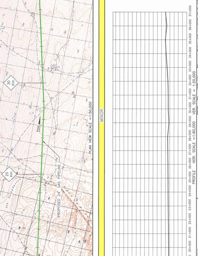

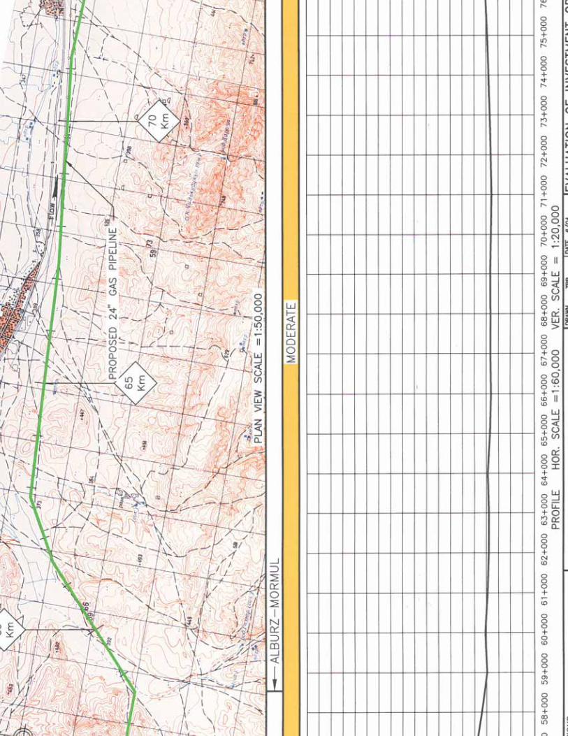
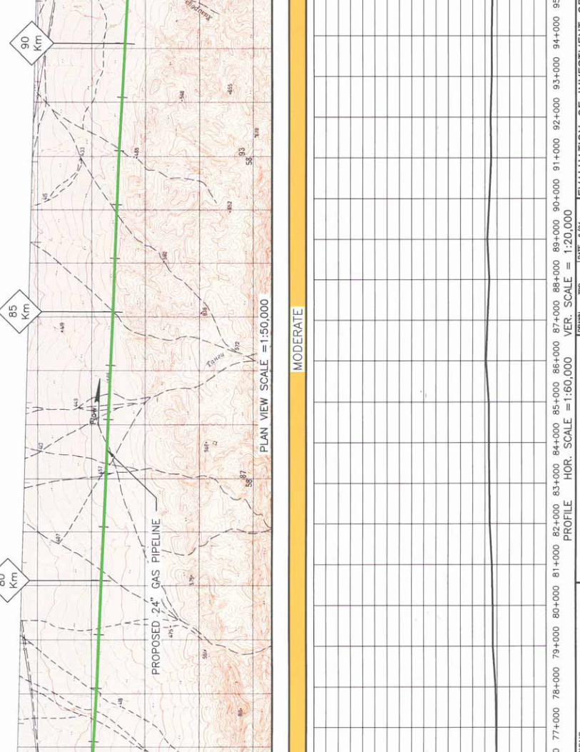

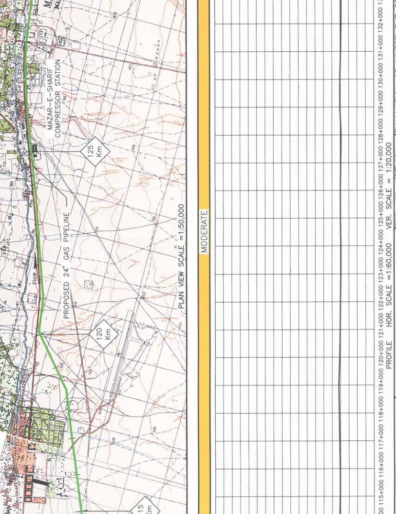

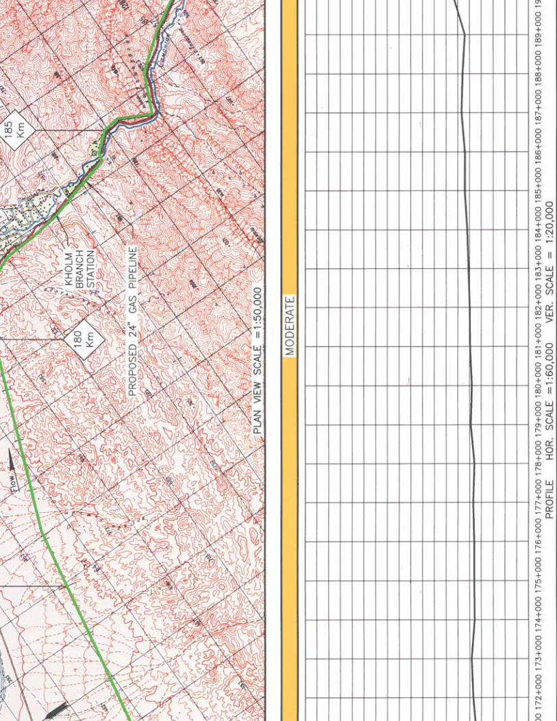

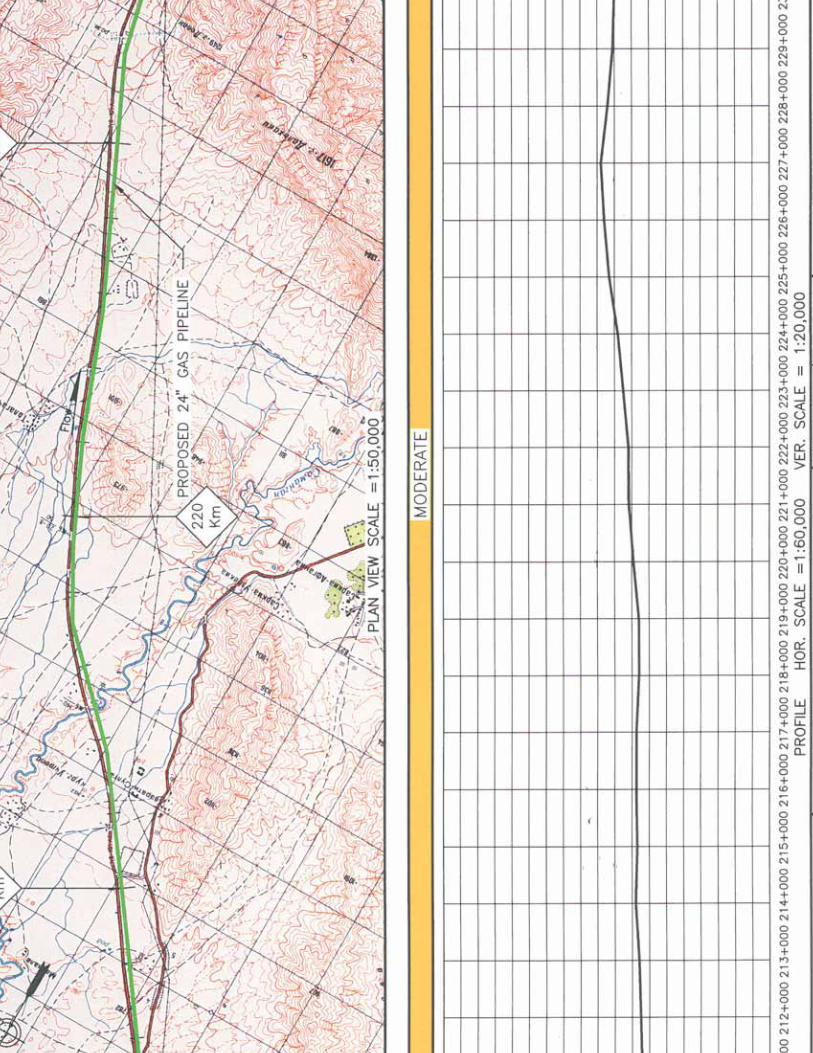
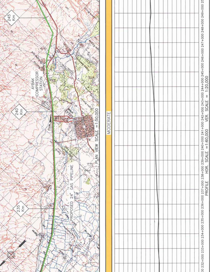


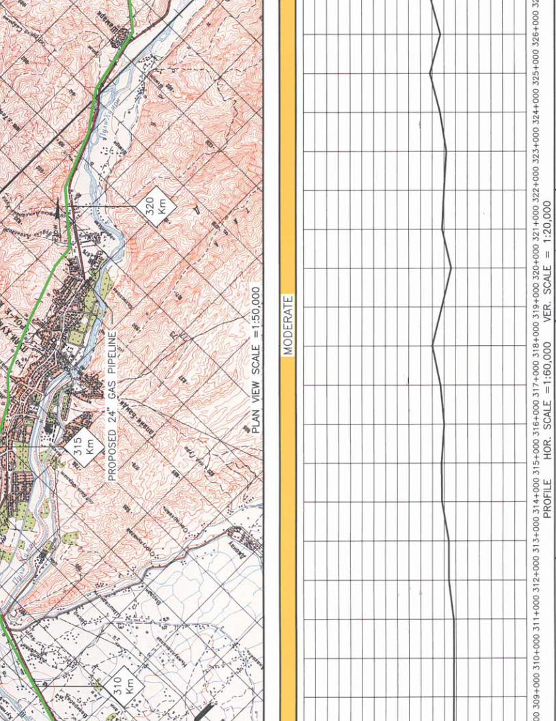


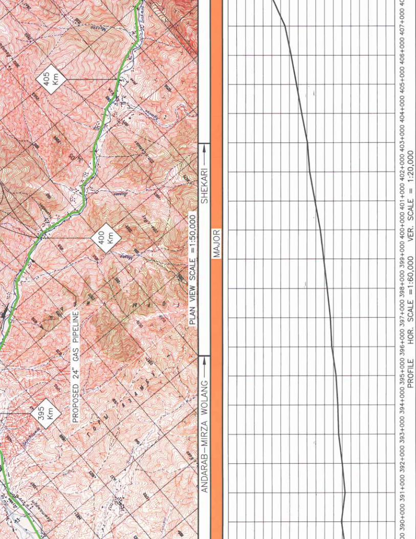

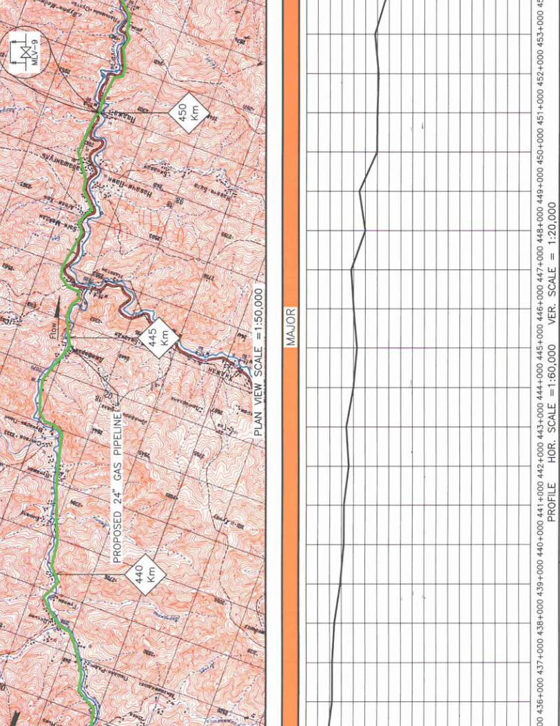
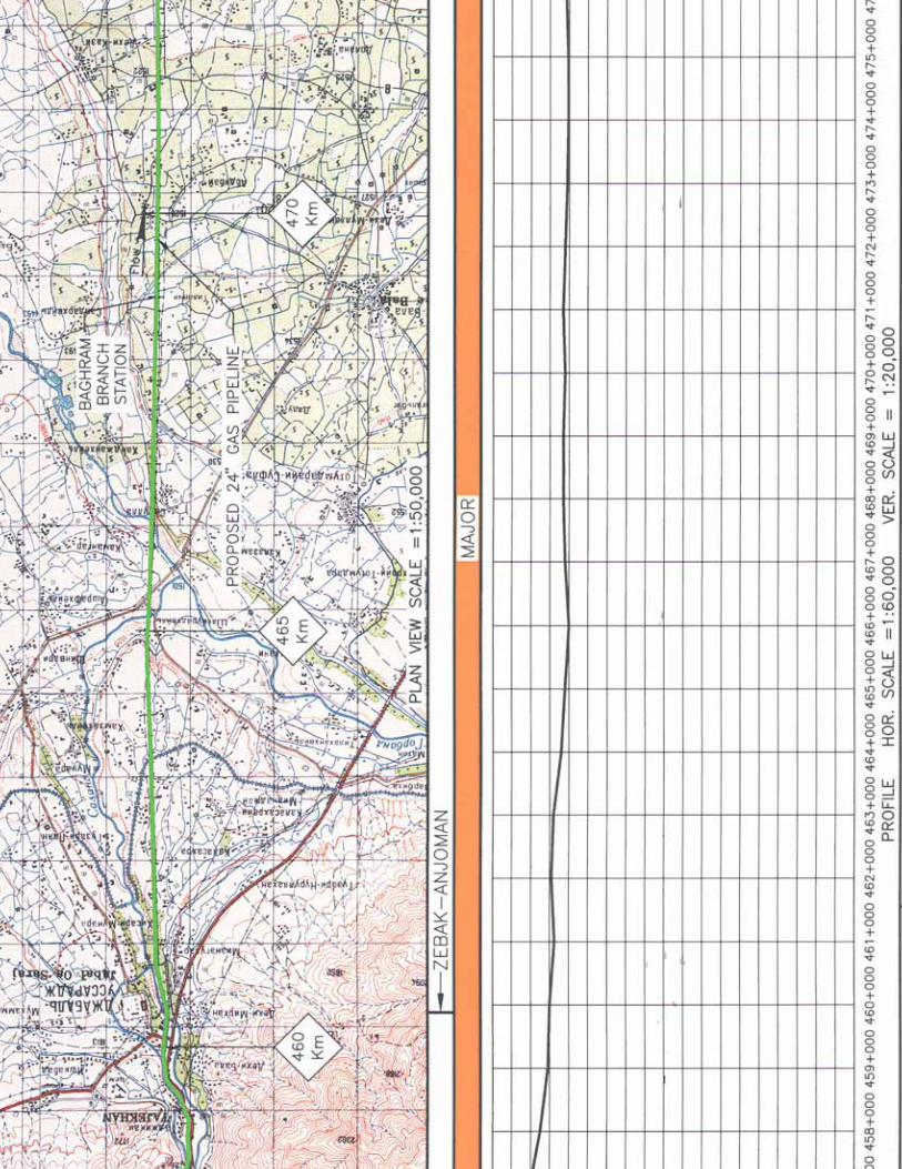

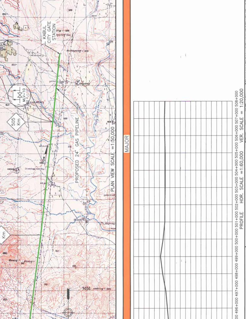


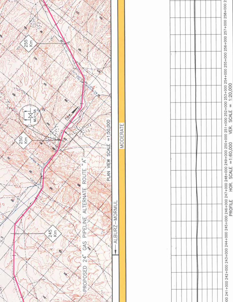

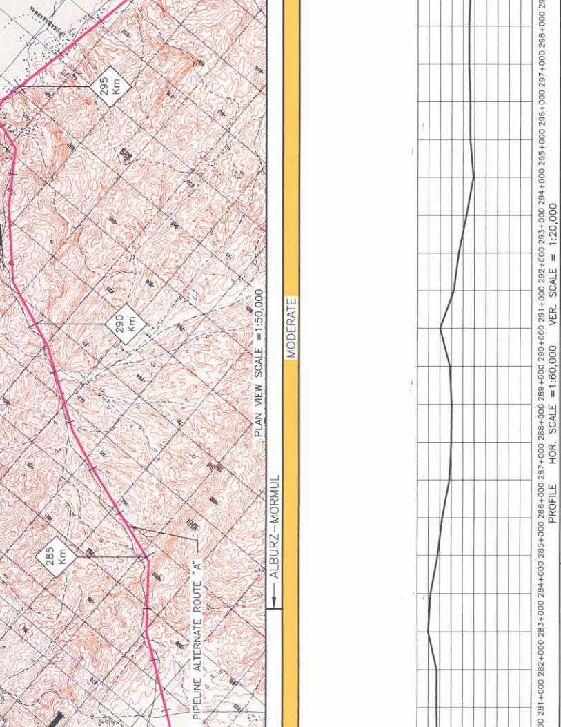
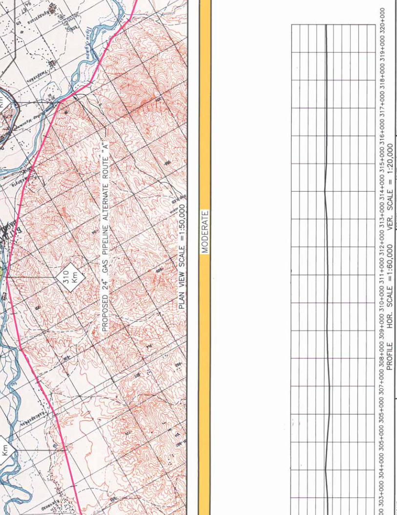

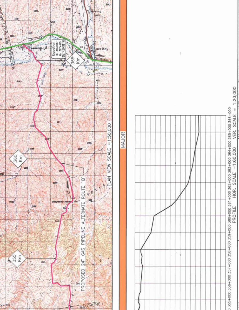
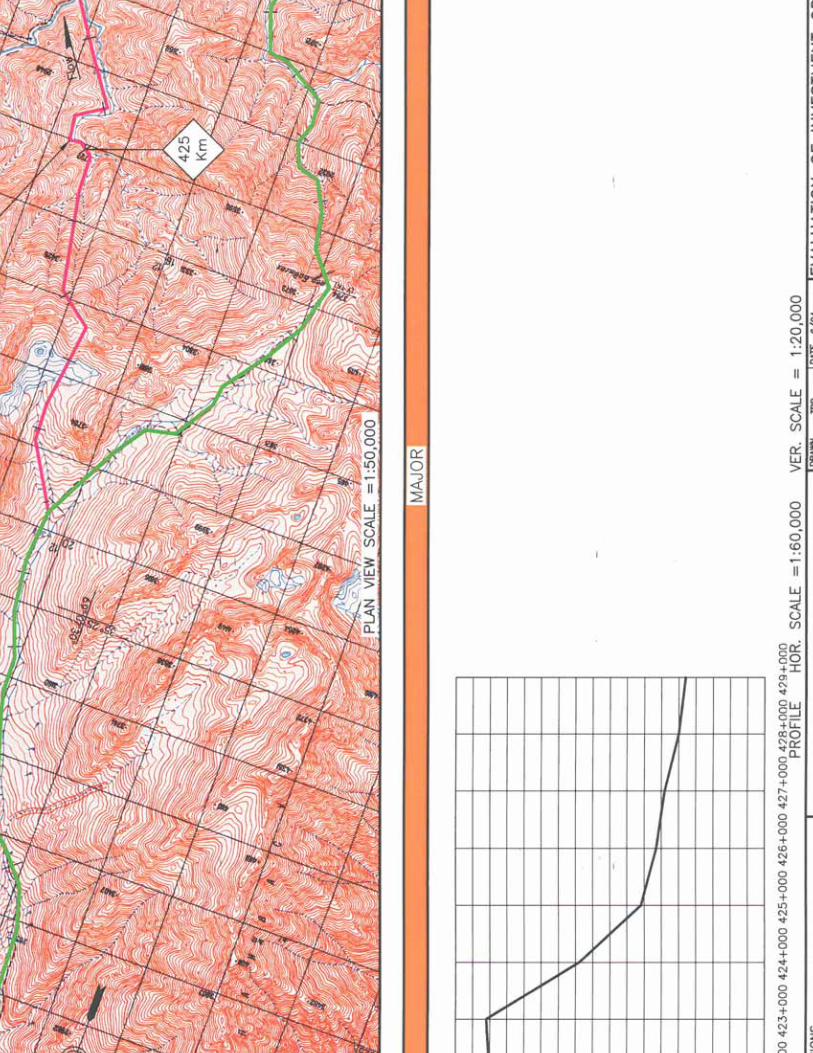
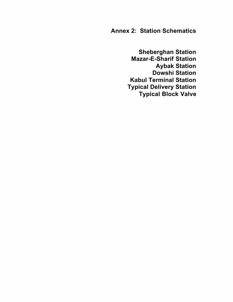
Annex 2: Station Schematics
Sheberghan StationMazar-E-Sharif Station
Aybak StationDowshi Station
Kabul Terminal StationTypical Delivery Station
Typical Block Valve

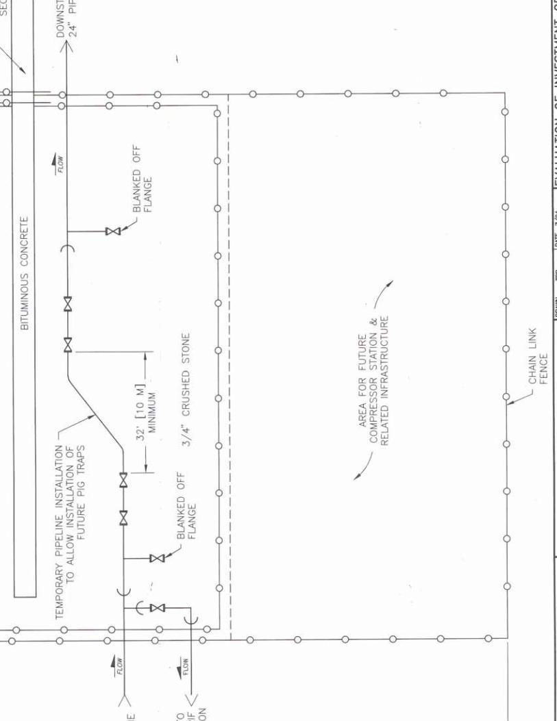


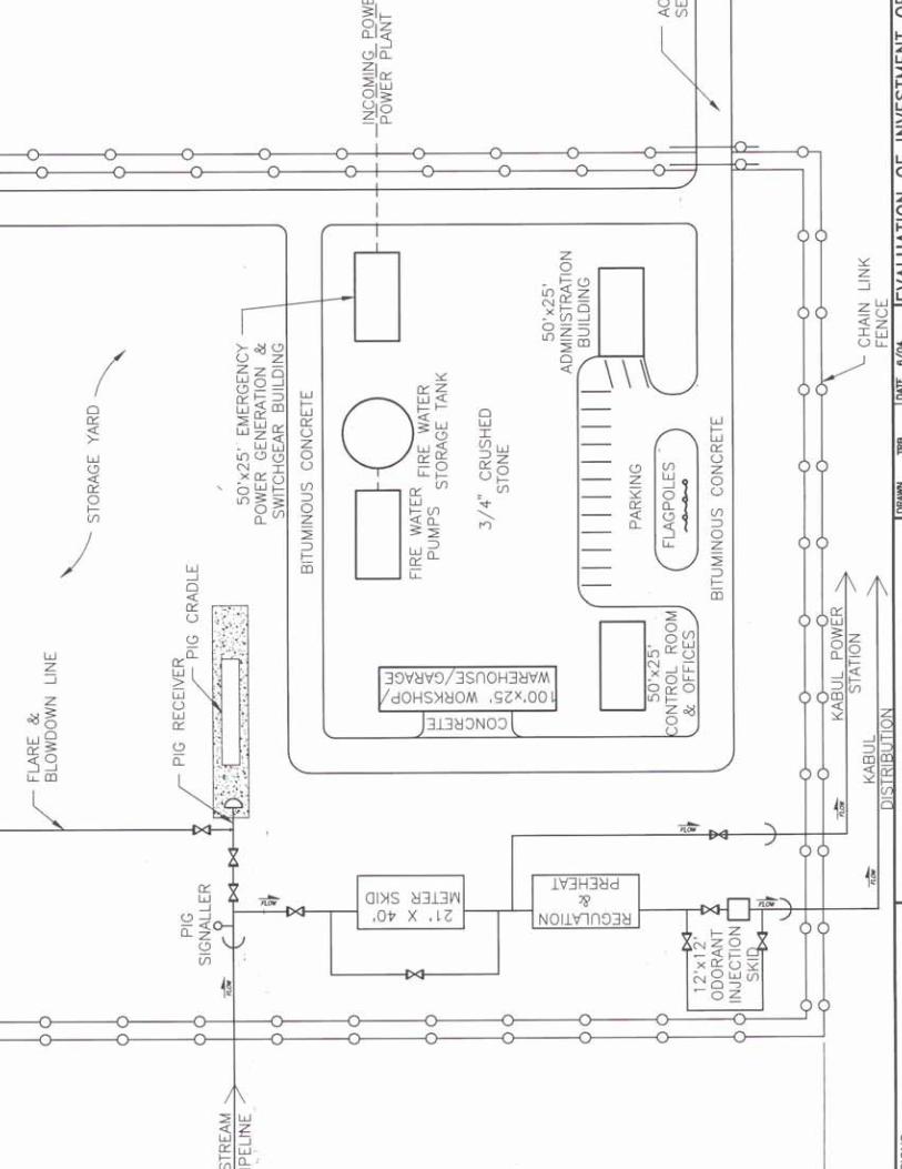


Annex 3: Terrain, Land Use and Seismic Maps


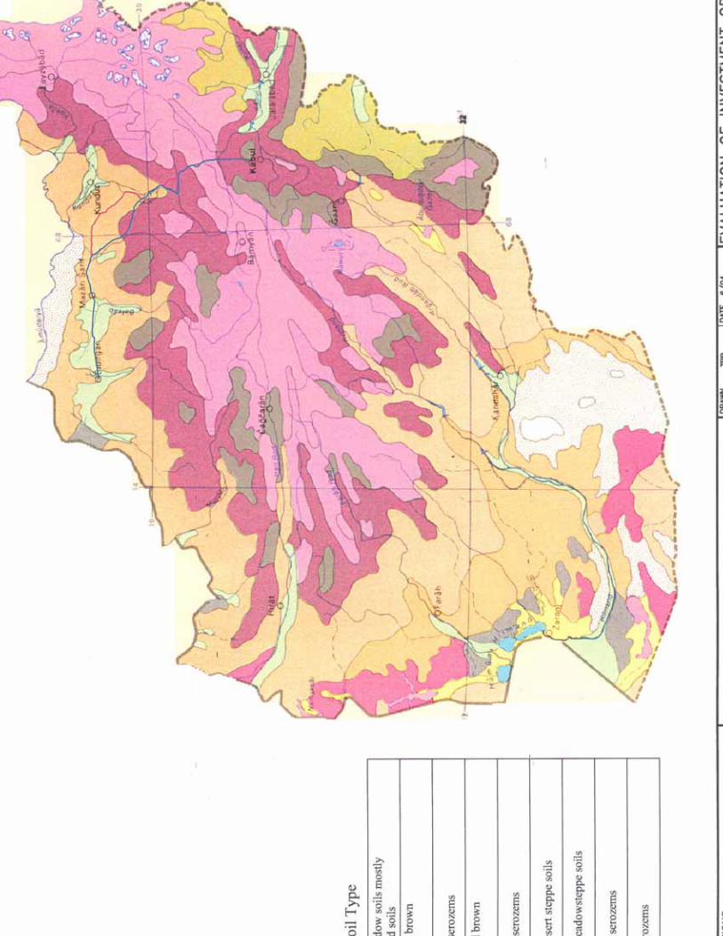


Annex 4: Conceptual Cost Estimate
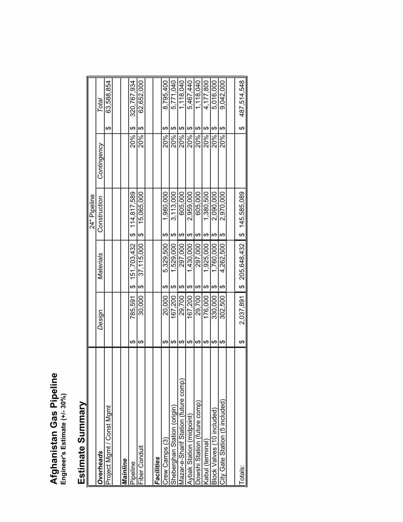
Afg
hani
stan
Gas
Pip
elin
eEn
gine
er's
Est
imat
e (+
/- 30
%)
Estim
ate
Sum
mar
y
Overheads
Des
ign
Mat
eria
lsC
onst
ruct
ion
Con
tinge
ncy
Tota
lP
roje
ct M
gmt /
Con
st M
gmt
63,5
88,8
54$
Mainline
Pip
elin
e78
5,59
1$
151,
703,
432
$
114,
817,
589
$
20%
320,
767,
934
$
Fi
ber C
ondu
it30
,000
$
37,1
15,0
00$
15,0
65,0
00$
20%
62,6
52,0
00$
Facilities
Cre
w C
amps
(3)
20,0
00$
5,
329,
500
$
1,98
0,00
0$
20
%8,
795,
400
$
She
berg
han
Sta
tion
(orig
in)
167,
200
$
1,
529,
000
$
3,11
3,00
0$
20
%5,
771,
040
$
Maz
ar-e
-Sha
rif S
tatio
n (fu
ture
com
p)29
,700
$
297,
000
$
60
5,00
0$
20%
1,11
8,04
0$
A
ybak
Sta
tion
(mid
poin
t)16
7,20
0$
1,43
0,00
0$
2,
959,
000
$
20%
5,46
7,44
0$
D
owsh
i Sta
tion
(futu
re c
omp)
29,7
00$
29
7,00
0$
605,
000
$
20
%1,
118,
040
$
Kab
ul (t
erm
inal
)17
6,00
0$
1,92
5,00
0$
1,
380,
500
$
20%
4,17
7,80
0$
B
lock
Val
ves
(10
incl
uded
)33
0,00
0$
1,76
0,00
0$
2,
090,
000
$
20%
5,01
6,00
0$
C
ity G
ate
Sta
tion
(5 in
clud
ed)
302,
500
$
4,
262,
500
$
2,97
0,00
0$
20
%9,
042,
000
$
Tota
ls:
2,03
7,89
1$
20
5,64
8,43
2$
14
5,58
5,08
9$
48
7,51
4,54
8$
24" P
ipel
ine

Afg
hani
stan
Gas
Pip
elin
eEn
gine
er's
Est
imat
e (+
/- 30
%)
24"
Pipe
line
- Mai
nlin
eC
ost p
erD
esig
nTo
tal M
ater
ials
Con
stru
ctio
nTo
tal
Met
ers
Feet
Foot
Cro
ss C
ount
ry -
Agr
icul
tura
l12
6,00
041
3,38
655
$
165,
354
$
$3
4,22
8,34
822
,736
,221
$
57
,129
,923
$
C
ross
Cou
ntry
- D
eser
t17
6,00
057
7,42
855
$
230,
971
$
$4
7,81
1,02
531
,758
,531
$
79
,800
,527
$
C
ross
Cou
ntry
-Mou
ntai
nous
(Lig
ht)
153,
000
501,
969
60$
20
0,78
7$
$41,
562,
993
30,1
18,1
11$
71,8
81,8
92$
Cro
ss C
ount
ry -
Mou
ntai
nous
(Hea
vy)
50,0
0016
4,04
280
$
65,6
17$
$1
3,58
2,67
813
,123
,360
$
26
,771
,654
$
B
last
ing
80,0
0026
2,46
745
$
104,
987
$
$1
3,58
2,67
811
,811
,024
$
25
,498
,688
$
B
ores
3,00
09,
843
400
$
7,
874
$
$814
,961
3,93
7,00
8$
4,75
9,84
3$
C
P/A
C M
itiga
tion
508,
000
1,66
6,66
70.
80$
10
,000
$
$1
20,7
501,
333,
333
$
1,
464,
083
$S
ub-T
otal
s50
8,00
01,
666,
667
785,
591
$
15
1,70
3,43
2$
114,
817,
589
$
267,
306,
612
$
Leng
th

Afg
hani
stan
Gas
Pip
elin
eEn
gine
er's
Est
imat
e (+
/- 30
%)
Faci
litie
s - 2
4" P
ipel
ine
400
MM
SCF/
DC
ost
Des
ign
Mat
eria
lsC
onst
ruct
ion
Mar
kup
Tota
lS
ourc
e/C
omm
ents
Pip
elin
e O
rigin
Sta
tion
Pip
elin
e Ti
e-In
w/P
ig B
arre
ls7,
000
$
270,
000
$
180,
000
$
10%
502,
700
$
Pow
ell C
ontro
ls fo
r Val
ves
(24"
- $1
8K) D
uke
for B
arre
lsS
ite D
evel
opm
ent
15,0
00$
15,0
00$
500,
000
$
10%
583,
000
$
Sca
led
from
Met
er S
tatio
n C
osts
Sta
tion
Pip
ing
20,0
00$
140,
000
$
1,40
0,00
0$
10%
1,71
6,00
0$
Flar
e/B
low
dow
n S
yste
m10
,000
$
50
,000
$
70
,000
$
10%
143,
000
$
Con
trols
5,00
0$
35
,000
$
20
,000
$
10%
66,0
00$
No
Com
pres
sor C
ontro
lsE
mer
genc
y G
ener
ator
5,00
0$
15
0,00
0$
10
,000
$
10%
181,
500
$
Cat
, tur
boch
arge
d, 2
00 k
W, b
ased
on
expe
rienc
eE
lect
rical
Sw
itchg
ear
10,0
00$
120,
000
$
40,0
00$
10
%18
7,00
0$
S
nied
er o
n-lin
e ca
talo
g
Adm
in B
uild
ing
20,0
00$
125,
000
$
125,
000
$
10%
297,
000
$
Mea
ns M
460
Offi
ce B
uild
ing
2-4
Sto
ries
Con
trol B
uild
ing
20,0
00$
125,
000
$
125,
000
$
10%
297,
000
$
Mea
ns M
460
Offi
ce B
uild
ing
2-4
Sto
ries
Wor
ksho
p20
,000
$
18
0,00
0$
18
0,00
0$
10
%41
8,00
0$
M
eans
M26
0 G
arag
e, A
uto
Sal
esW
areh
ouse
Gar
age
Bui
ldin
g20
,000
$
18
0,00
0$
18
0,00
0$
10
%41
8,00
0$
M
eans
M26
0 G
arag
e, A
uto
Sal
esS
ub-T
otal
s15
2,00
0$
1,39
0,00
0$
2,83
0,00
0$
4,80
9,20
0$
Ayb
ak S
tatio
n
Pip
elin
e Ti
e-In
w/P
ig B
arre
ls7,
000
$
270,
000
$
180,
000
$
10%
502,
700
$
Pow
ell C
ontro
ls fo
r Val
ves
(24"
- $1
8K) D
uke
for B
arre
lsS
ite D
evel
opm
ent
15,0
00$
15,0
00$
500,
000
$
10%
583,
000
$
Sca
led
from
Met
er s
tatio
n co
sts
Sta
tion
Pip
ing
20,0
00$
140,
000
$
1,40
0,00
0$
10%
1,71
6,00
0$
Flar
e/B
low
dow
n S
yste
m10
,000
$
50
,000
$
70
,000
$
10%
143,
000
$
Con
trols
5,00
0$
35
,000
$
20
,000
$
10%
66,0
00$
No
Com
pres
sor C
ontro
lsE
mer
genc
y G
ener
ator
5,00
0$
15
0,00
0$
10
,000
$
10%
181,
500
$
Cat
, tur
boch
arge
d, 2
00 k
W, b
ased
on
expe
rienc
eE
lect
rical
Sw
itchg
ear
10,0
00$
120,
000
$
40,0
00$
10
%18
7,00
0$
S
nied
er o
n-lin
e ca
talo
g
Fire
Wat
er S
yste
m20
,000
$
14
0,00
0$
90
,000
$
10%
275,
000
$
Est
imat
ed fr
om s
imila
r pro
ject
s
Aux
iliar
y B
uild
ing
20,0
00$
75,0
00$
75,0
00$
10
%18
7,00
0$
M
eans
M66
0 Te
leph
one
Exc
hang
eA
dmin
Bui
ldin
g20
,000
$
12
5,00
0$
12
5,00
0$
10
%29
7,00
0$
M
eans
M46
0 O
ffice
Bui
ldin
g 2-
4 S
torie
s

Afg
hani
stan
Gas
Pip
elin
eEn
gine
er's
Est
imat
e (+
/- 30
%)
Faci
litie
s - 2
4" P
ipel
ine
400
MM
SCF/
DC
ost
War
ehou
se G
arag
e B
uild
ing
20,0
00$
180,
000
$
180,
000
$
10%
418,
000
$
Mea
ns M
260
Gar
age,
Aut
o S
ales
Sub
-Tot
als
152,
000
$
1,
300,
000
$
2,
690,
000
$
4,
556,
200
$
Futu
re S
tatio
n
Pip
elin
e Ti
e-In
w/n
o P
ig B
arre
ls7,
000
$
220,
000
$
180,
000
$
10%
447,
700
$
Pow
ell C
ontro
ls fo
r Val
ves
(24"
- $1
8K)
Site
Dev
elop
men
t15
,000
$
15
,000
$
35
0,00
0$
10
%41
8,00
0$
S
cale
d fro
m M
eter
sta
tion
cost
s
Con
trols
5,00
0$
35
,000
$
20
,000
$
10%
66,0
00$
Sub
-Tot
als
27,0
00$
270,
000
$
550,
000
$
931,
700
$
Pip
elin
e Te
rmin
us S
tatio
n
Site
Dev
elop
men
t10
,000
$
15
,000
$
15
0,00
0$
10
%19
2,50
0$
P
ig B
arre
l5,
000
$
150,
000
$
100,
000
$
10%
280,
500
$
Pow
ell C
ontro
ls fo
r Val
ves
(24"
- $1
8K) D
uke
for B
arre
lsFl
are/
Blo
wdo
wn
Sys
tem
10,0
00$
50,0
00$
70,0
00$
10
%14
3,00
0$
M
eter
ing
Sys
tem
15,0
00$
160,
000
$
135,
000
$
10%
341,
000
$
Bas
ed o
n Fr
amin
gham
96M
M/D
(out
door
inst
alla
tion,
sim
ilar t
o W
CE
)R
egul
atio
n/O
dora
nt S
yste
m15
,000
$
28
0,00
0$
13
5,00
0$
10
%47
3,00
0$
B
ased
on
Fram
ingh
am 9
6MM
/D (o
utdo
or in
stal
latio
n, s
imila
r to
WC
E)
Pre
heat
Sys
tem
5,00
0$
22
0,00
0$
75
,000
$
10%
330,
000
$
Bas
ed o
n Fr
amin
gham
Adm
in B
uild
ing
20,0
00$
125,
000
$
125,
000
$
10%
297,
000
$
Mea
ns M
460
Offi
ce B
uild
ing
2-4
Sto
ries
Con
trol B
uild
ing
20,0
00$
125,
000
$
125,
000
$
10%
297,
000
$
Mea
ns M
460
Offi
ce B
uild
ing
2-4
Sto
ries
Wor
ksho
p20
,000
$
18
0,00
0$
18
0,00
0$
10
%41
8,00
0$
M
eans
M26
0 G
arag
e, A
uto
Sal
es
Fire
Wat
er S
yste
m20
,000
$
14
0,00
0$
90
,000
$
10%
275,
000
$
Est
imat
ed fr
om s
imila
r pro
ject
sE
mer
genc
y G
ener
ator
5,00
0$
15
0,00
0$
10
,000
$
10%
181,
500
$
Cat
, tur
boch
arge
d, 2
00 k
W, b
ased
on
expe
rienc
eE
lect
rical
Sw
itchg
ear
10,0
00$
120,
000
$
40,0
00$
10
%18
7,00
0$
S
nied
er o
n-lin
e ca
talo
gC
ontro
ls5,
000
$
35,0
00$
20
,000
$
10%
66,0
00$
B
ased
on
Fram
ingh
amS
ub-T
otal
s16
0,00
0$
1,75
0,00
0$
1,25
5,00
0$
3,48
1,50
0$
Mai
nlin
e V
alve
s50
km s
paci
ng (1
0 re
quire
d)
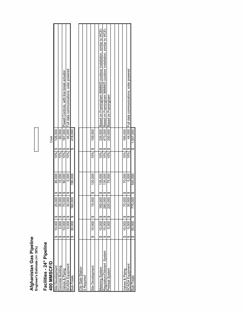
Afg
hani
stan
Gas
Pip
elin
eEn
gine
er's
Est
imat
e (+
/- 30
%)
Faci
litie
s - 2
4" P
ipel
ine
400
MM
SCF/
DC
ost
Site
Dev
elop
men
t10
,000
$
25
,000
$
80
,000
$
10%
126,
500
$
Con
cret
e B
uild
ing
5,00
0$
35
,000
$
15
,000
$
10%
60,5
00$
Val
ves
& P
ipin
g10
,000
$
70
,000
$
90
,000
$
10%
187,
000
$
Pow
ell C
ontro
ls, w
ith li
ne b
reak
act
uato
rS
CA
DA
Equ
ipm
ent
5,00
0$
30
,000
$
5,00
0$
10%
44,0
00$
Fu
ll da
ta c
omm
unic
atio
ns, s
olar
pow
ered
Sub
-Tot
als
30,0
00$
160,
000
$
190,
000
$
418,
000
$
City
Gat
e S
tatio
n5
Req
uire
d
Site
Dev
elop
men
t10
,000
$
15
,000
$
12
0,00
0$
10
%15
9,50
0$
Met
erin
g S
yste
m10
,000
$
16
0,00
0$
13
5,00
0$
10
%33
5,50
0$
B
ased
on
Fram
ingh
am 9
6MM
/D (o
utdo
or in
stal
latio
n, s
imila
r to
WC
E)
Reg
ulat
ion/
Odo
rant
Sys
tem
15,0
00$
280,
000
$
135,
000
$
10%
473,
000
$
Bas
ed o
n Fr
amin
gham
96M
M/D
(out
door
inst
alla
tion,
sim
ilar t
o W
CE
)P
rehe
at S
yste
m5,
000
$
220,
000
$
75,0
00$
10
%33
0,00
0$
B
ased
on
Fram
ingh
am
Val
ves
& P
ipin
g10
,000
$
70
,000
$
70
,000
$
10%
165,
000
$
SC
AD
A E
quip
men
t5,
000
$
30,0
00$
5,
000
$
10
%44
,000
$
Full
data
com
mun
icat
ions
, sol
ar p
ower
edS
ub-T
otal
s55
,000
$
77
5,00
0$
54
0,00
0$
1,
507,
000
$

Afg
hani
stan
Gas
Pip
elin
eEn
gine
er's
Est
imat
e (+
/- 30
%)
Fibe
r Opt
ic S
yste
mC
ost
Des
ign
Mat
eria
lsC
onst
ruct
ion
Mar
kup
Tota
lS
ourc
e/C
omm
ents
Sin
gle
Mod
e m
ulti
fiber
net
wor
k
Mai
nlin
e (5
08km
)15
,000
$
37
,000
,000
$
15,0
00,0
00$
10
%57
,216
,500
$A
mpl
ifier
Site
s5,
000
$
15,0
00$
15,0
00$
10
%38
,500
$
R
epea
ter S
ites
(RR
R)
10,0
00$
100,
000
$
50,0
00$
10
%17
6,00
0$
Sub
-Tot
als
30,0
00$
37,1
15,0
00$
15
,065
,000
$ 57
,431
,000
$
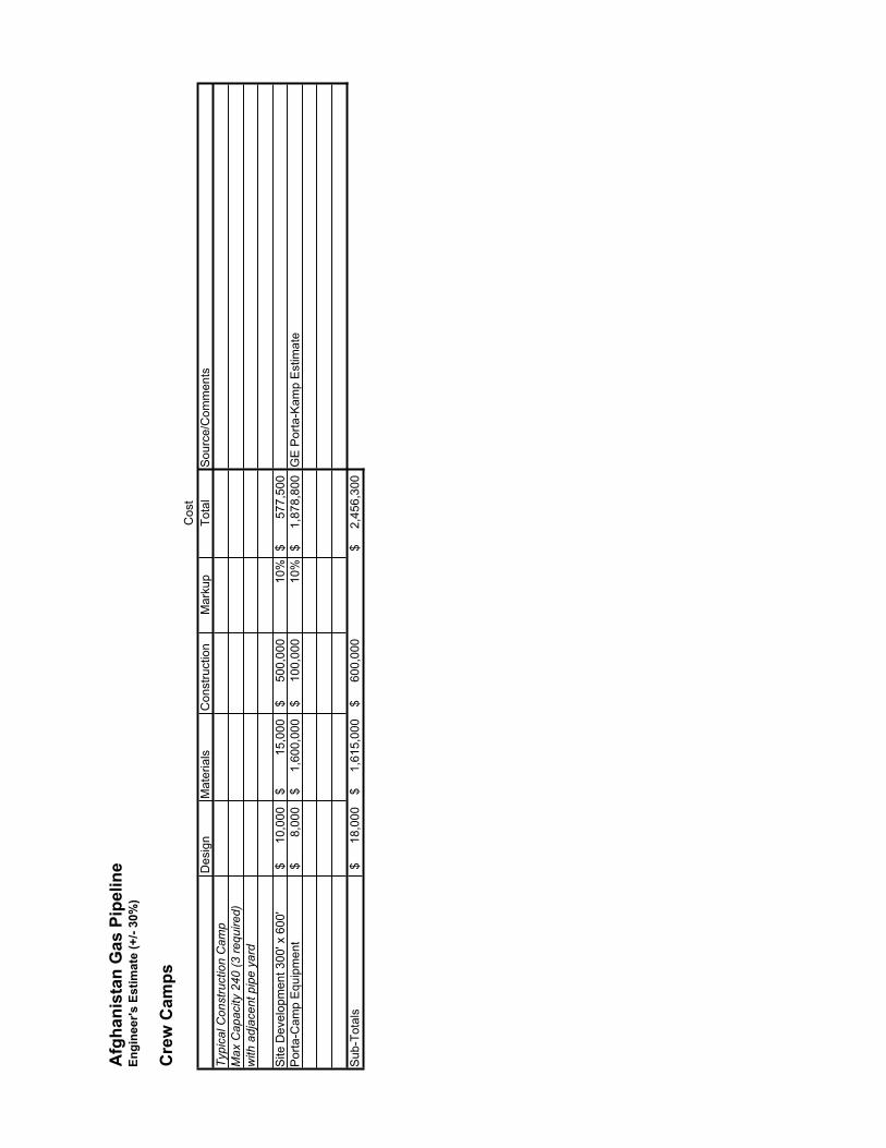
Afg
hani
stan
Gas
Pip
elin
eEn
gine
er's
Est
imat
e (+
/- 30
%)
Cre
w C
amps
Cos
tD
esig
nM
ater
ials
Con
stru
ctio
nM
arku
pTo
tal
Sou
rce/
Com
men
tsTy
pica
l Con
stru
ctio
n C
amp
Max
Cap
acity
240
(3 re
quire
d)w
ith a
djac
ent p
ipe
yard
Site
Dev
elop
men
t 300
' x 6
00'
10,0
00$
15,0
00$
500,
000
$
10
%57
7,50
0$
P
orta
-Cam
p E
quip
men
t8,
000
$
1,60
0,00
0$
100,
000
$
10
%1,
878,
800
$
G
E P
orta
-Kam
p E
stim
ate
Sub
-Tot
als
18,0
00$
1,61
5,00
0$
600,
000
$
2,
456,
300
$

Annex 5: Calculations

2009
2010
2011
2012
2013
2014
2015
2016
2017
2018
2019
2020
2021
2W
ERFU
EL
CO
NS
UM
PTI
ON
MM
SC
F/Y
R7,
417
9,32
3
12
,019
14
,474
16
,968
19
,792
22
,311
22
,769
23
,524
26
,444
29
,755
30
,860
33
,859
35
,
DA
ILY
FU
EL
CO
NS
UM
PT
MM
SC
FD20
26
33
40
46
54
61
62
64
72
82
85
93
LOA
D F
AC
TOR
50%
53%
57%
56%
55%
55%
55%
57%
58%
57%
58%
59%
58%
ENER
ATI
ON
MM
SC
F/Y
R4,
683
6,12
4
7,
769
9,64
0
11
,761
13
,986
16
,414
19
,099
22
,021
25
,145
28
,236
31
,472
34
,968
38
,
MM
SC
F/Y
R25
4
336
43
1
541
66
7
803
95
2
1,11
9
1,
303
1,50
6
1,
720
1,95
1
2,
204
2,
M
MS
CF/
YR
195
25
8
329
41
1
503
60
2
710
83
1
960
1,
092
1,22
8
1,
372
1,52
8
1,
MM
SC
F/Y
R45
1
480
59
9
732
87
9
1,03
9
1,
211
1,39
8
1,
598
1,80
5
2,
026
2,25
6
2,
504
2,
M
MS
CF/
YR
584
75
1
938
1,
146
1,37
7
1,
634
1,91
3
2,
216
2,54
4
2,
893
3,26
3
3,
648
4,02
0
4 ,
AN
D S
ELF-
GEN
ERA
TIO
NM
MS
CF/
YR
6,16
7
7,
949
10,0
66
12,4
69
15,1
89
18,0
64
21,2
00
24,6
62
28,4
25
32,4
41
36,4
73
40,6
99
45,2
23
50,
ER
AG
E D
AIL
Y D
EMA
ND
MM
SC
FD17
22
28
34
42
49
58
68
78
89
100
11
2
124
LO
AD
FA
CTO
R30
%30
%30
%30
%30
%30
%30
%30
%30
%30
%30
%30
%30
%
OTA
L A
NN
UA
L D
EMA
ND
BSC
F14
17
22
27
32
38
44
47
52
59
66
72
79
GE
DA
ILY
GA
S D
EMA
ND
MM
SCFD
37
47
61
74
88
10
4
119
13
0
142
16
1
181
19
6
217
12
4
20
0920
1020
1120
1220
1320
1420
1520
1620
1720
1820
1920
2020
212
S D
EMA
ND
MSC
F/H
R1,
679
2,00
0
2,
406
2,95
0
3,
507
4,07
8
4,
646
4,59
1
4,
597
5,25
0
5,
883
5,93
8
6,
613
6,
ENER
ATI
ON
MS
CF/
HR
1,78
1
2,
329
2,95
4
3,
666
4,47
2
5,
318
6,24
2
7,
263
8,37
3
9,
562
10,7
37
11,9
68
13,2
97
14,
M
SC
F/H
R96
128
16
4
206
25
4
305
36
2
425
49
6
573
65
4
742
83
8
MS
CF/
HR
74
98
12
5
156
19
1
229
27
0
316
36
5
415
46
7
522
58
1
MS
CF/
HR
172
18
3
228
27
8
334
39
5
461
53
2
608
68
7
770
85
8
952
1 ,
MS
CF/
HR
222
28
6
357
43
6
524
62
1
727
84
3
967
1,
100
1,24
1
1,
387
1,52
8
1,
ATI
ON
MS
CF/
HR
2,34
5
3,
023
3,82
8
4,
741
5,77
6
6,
869
8,06
1
9,
378
10,8
09
12,3
36
13,8
69
15,4
76
17,1
96
19,
MSC
F/H
R4,
024
5,02
2
6,
234
7,69
1
9,
283
10,9
47
12,7
07
13,9
69
15,4
06
17,5
86
19,7
52
21,4
14
23,8
09
25,
M
MSC
FD97
121
15
0
185
22
3
263
30
5
335
37
0
422
47
4
514
57
1
R39
%39
%40
%40
%40
%39
%39
%39
%38
%38
%38
%38
%38
%
220
220
220
220
220
220
220
220
220
220
220
220
220
220
SO
R10
010
010
010
010
010
010
010
0S
SO
R10
010
0
100
10
0
100
3
4315
502
3030
3022
022
0
220
22
0
223
26
3
320
33
5
370
42
2
450
45
0
450

0720
0820
0920
1020
1120
1220
1320
1420
1520
1620
1720
1820
1920
2020
2120
2220
2320
2420
2520
2620
2720
2820
2920
3020
31
96.6
112
0.57
149.
6518
4.63
222.
8425
2.48
292.
9632
1.25
353.
6040
3.65
434.
9947
0.33
522.
9856
5.44
626.
6252
1.03
544.
6454
4.64
544.
6454
4.64
544.
6454
4.64
544.
641.
001.
251.
551.
912.
302.
613.
033.
323.
664.
174.
504.
865.
415.
856.
485.
395.
635.
635.
635.
635.
635.
635.
6320
0.00
200.
0020
0.00
200.
0020
0.00
200.
0020
0.00
200.
0020
0.00
200.
0020
0.00
200.
0020
0.00
200.
0020
0.00
200.
0020
0.00
200.
0020
0.00
200.
0020
0.00
200.
0020
0.0 0
82.8
482
.84
82.8
482
.84
82.8
482
.84
82.8
482
.84
82.8
482
.84
82.8
482
.84
82.8
482
.84
82.8
482
.84
82.8
482
.84
82.8
411
7.16
117.
1611
7.16
117.
1611
7.16
117.
1611
7.16
117.
1611
7.16
117.
1611
7.16
117.
1611
7.16
117.
1611
7.16
117.
1620
0.00
200.
0020
0.00
200.
0028
2.84
282.
8428
2.84
400.
0040
0.00
400.
0040
0.00
400.
0040
0.00
400.
0040
0.00
400.
0040
0.00
400.
0040
0.00
400.
0040
0.00
400.
0040
0.0 0
96.6
112
0.57
149.
6518
4.63
222.
8425
2.48
282.
8432
1.25
353.
6040
0.00
400.
0040
0.00
400.
0040
0.00
400.
0040
0.00
400.
0040
0.00
400.
0040
0.00
400.
0040
0.00
400.
001.
008
1.25
71.
561
1.92
52.
324
2.63
32.
950
3.35
03.
688
4.17
14.
171
4.17
14.
171
4.17
14.
171
4.17
14.
171
4.17
14.
171
4.17
14.
171
4.17
14.
171
48%
60%
75%
92%
79%
89%
100%
80%
88%
100%
100%
100%
100%
100%
100%
100%
100%
100%
100%
100%
100%
100%
100%
34
56
78
910
1112
1314
1516
1718
1920
2122
2324
2526
2737
,951
,840
$
47,3
62,0
35$
58
,786
,669
$
72,5
30,3
49$
87
,538
,607
$
99,1
83,8
21$
11
1,10
9,45
6$
126,
198,
985
$
13
8,90
6,43
5$
157,
132,
500
$
15
7,13
2,50
0$
157,
132,
500
$
15
7,13
2,50
0$
157,
132,
500
$
15
7,13
2,50
0$
157,
132,
500
$
157,
132,
500
$
157,
132,
500
$
157,
132,
500
$
157,
132,
500
$
157,
132,
500
$
157,
132,
500
$
157,
132,
500
$
06)
($47
,981
,103
)($
15,4
67,4
40)
($37
,236
,080
)4,
000,
000
$
4,
000,
000
$
4,
000,
000
$
4,
000,
000
$
4,
000,
000
$
4,
000,
000
$
4,
000,
000
$
4,
000,
000
$
4,
000,
000
$
4,
000,
000
$
4,
000,
000
$
4,
000,
000
$
4,
000,
000
$
4,
000,
000
$
4,
000,
000
$
4,
000,
000
$
4,
000,
000
$
4,
000,
000
$
4,
000,
000
$
4,
000,
000
$
4,
000,
000
$
4,
000,
000
$
4,
000,
000
$
06)
($47
,981
,103
)41
,951
,840
$
51,3
62,0
35$
62
,786
,669
$
61,0
62,9
09$
91
,538
,607
$
103,
183,
821
$
77
,873
,376
$
130,
198,
985
$
14
2,90
6,43
5$
161,
132,
500
$
16
1,13
2,50
0$
161,
132,
500
$
16
1,13
2,50
0$
161,
132,
500
$
16
1,13
2,50
0$
161,
132,
500
$
161,
132,
500
$
161,
132,
500
$
161,
132,
500
$
161,
132,
500
$
161,
132,
500
$
161,
132,
500
$
161,
132,
500
$
06)
($47
,981
,103
)
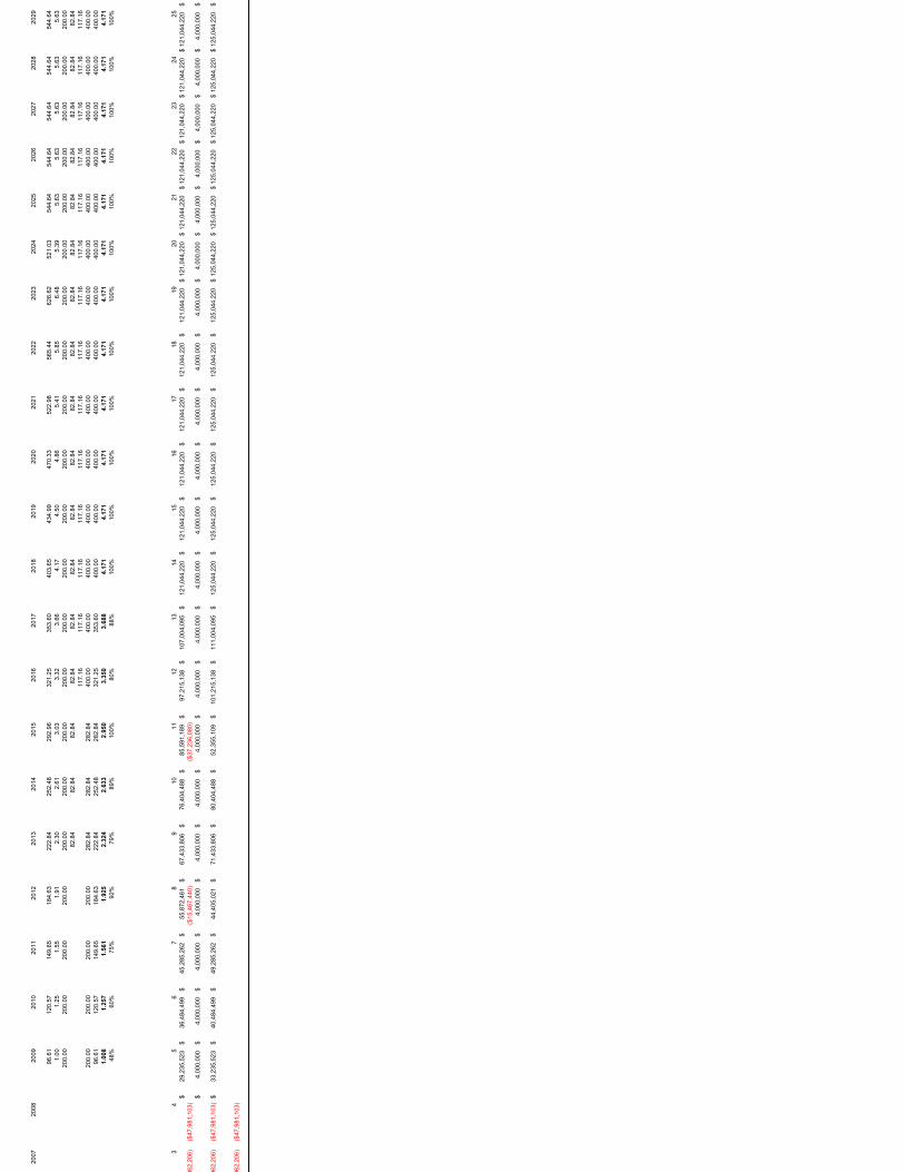
2007
2008
2009
2010
2011
2012
2013
2014
2015
2016
2017
2018
2019
2020
2021
2022
2023
2024
2025
2026
2027
2028
2029
96.6
112
0.57
149.
6518
4.63
222.
8425
2.48
292.
9632
1.25
353.
6040
3.65
434.
9947
0.33
522.
9856
5.44
626.
6252
1.03
544.
6454
4.64
544.
6454
4.64
544.
641.
001.
251.
551.
912.
302.
613.
033.
323.
664.
174.
504.
865.
415.
856.
485.
395.
635.
635.
635.
635.
6320
0.00
200.
0020
0.00
200.
0020
0.00
200.
0020
0.00
200.
0020
0.00
200.
0020
0.00
200.
0020
0.00
200.
0020
0.00
200.
0020
0.00
200.
0020
0.00
200.
0020
0.00
82.8
482
.84
82.8
482
.84
82.8
482
.84
82.8
482
.84
82.8
482
.84
82.8
482
.84
82.8
482
.84
82.8
482
.84
82.8
411
7.16
117.
1611
7.16
117.
1611
7.16
117.
1611
7.16
117.
1611
7.16
117.
1611
7.16
117.
1611
7.16
117.
1620
0.00
200.
0020
0.00
200.
0028
2.84
282.
8428
2.84
400.
0040
0.00
400.
0040
0.00
400.
0040
0.00
400.
0040
0.00
400.
0040
0.00
400.
0040
0.00
400.
0040
0.00
96.6
112
0.57
149.
6518
4.63
222.
8425
2.48
282.
8432
1.25
353.
6040
0.00
400.
0040
0.00
400.
0040
0.00
400.
0040
0.00
400.
0040
0.00
400.
0040
0.00
400.
001.
008
1.25
71.
561
1.92
52.
324
2.63
32.
950
3.35
03.
688
4.17
14.
171
4.17
14.
171
4.17
14.
171
4.17
14.
171
4.17
14.
171
4.17
14.
171
48%
60%
75%
92%
79%
89%
100%
80%
88%
100%
100%
100%
100%
100%
100%
100%
100%
100%
100%
100%
100%
34
56
78
910
1112
1314
1516
1718
1920
2122
2324
2529
,235
,523
$
36,4
84,4
99$
45
,285
,262
$
55,8
72,4
61$
67
,433
,806
$
76,4
04,4
88$
85
,591
,189
$
97,2
15,1
38$
10
7,00
4,09
5$
121,
044,
220
$
12
1,04
4,22
0$
121,
044,
220
$
12
1,04
4,22
0$
121,
044,
220
$
12
1,04
4,22
0$
121,
044,
220
$
121,
044,
220
$
121,
044,
220
$
121,
044,
220
$
121,
044,
220
$
121,
044,
220
$
1$
96
2,20
6)($
47,9
81,1
03)
($15
,467
,440
)($
37,2
36,0
80)
4,00
0,00
0$
4,
000,
000
$
4,00
0,00
0$
4,00
0,00
0$
4,00
0,00
0$
4,00
0,00
0$
4,00
0,00
0$
4,00
0,00
0$
4,00
0,00
0$
4,00
0,00
0$
4,00
0,00
0$
4,00
0,00
0$
4,00
0,00
0$
4,00
0,00
0$
4,00
0,00
0$
4,00
0,00
0$
4,00
0,00
0$
4,00
0,00
0$
4,00
0,00
0$
4,00
0,00
0$
4,00
0,00
0$
$
962,
206)
($47
,981
,103
)33
,235
,523
$
40,4
84,4
99$
49
,285
,262
$
44,4
05,0
21$
71
,433
,806
$
80,4
04,4
88$
52
,355
,109
$
101,
215,
138
$
11
1,00
4,09
5$
125,
044,
220
$
12
5,04
4,22
0$
125,
044,
220
$
12
5,04
4,22
0$
125,
044,
220
$
12
5,04
4,22
0$
125,
044,
220
$
125,
044,
220
$
125,
044,
220
$
125,
044,
220
$
125,
044,
220
$
125,
044,
220
$
1$
962,
206)
($47
,981
,103
)

2007
2008
2009
2010
2011
2012
2013
2014
2015
2016
2017
2018
2019
2020
2021
2022
2023
2024
2025
2026
2027
2028
2029
96.6
112
0.57
149.
6518
4.63
222.
8425
2.48
292.
9632
1.25
353.
6040
3.65
434.
9947
0.33
522.
9856
5.44
626.
6252
1.03
544.
6454
4.64
544.
6454
4.64
544.
641.
001.
251.
551.
912.
302.
613.
033.
323.
664.
174.
504.
865.
415.
856.
485.
395.
635.
635.
635.
635.
6320
0.00
200.
0020
0.00
200.
0020
0.00
200.
0020
0.00
200.
0020
0.00
200.
0020
0.00
200.
0020
0.00
200.
0020
0.00
200.
0020
0.00
200.
0020
0.00
200.
0020
0.00
82.8
482
.84
82.8
482
.84
82.8
482
.84
82.8
482
.84
82.8
482
.84
82.8
482
.84
82.8
482
.84
82.8
482
.84
82.8
411
7.16
117.
1611
7.16
117.
1611
7.16
117.
1611
7.16
117.
1611
7.16
117.
1611
7.16
117.
1611
7.16
117.
1620
0.00
200.
0020
0.00
200.
0028
2.84
282.
8428
2.84
400.
0040
0.00
400.
0040
0.00
400.
0040
0.00
400.
0040
0.00
400.
0040
0.00
400.
0040
0.00
400.
0040
0.00
96.6
112
0.57
149.
6518
4.63
222.
8425
2.48
282.
8432
1.25
353.
6040
0.00
400.
0040
0.00
400.
0040
0.00
400.
0040
0.00
400.
0040
0.00
400.
0040
0.00
400.
001.
008
1.25
71.
561
1.92
52.
324
2.63
32.
950
3.35
03.
688
4.17
14.
171
4.17
14.
171
4.17
14.
171
4.17
14.
171
4.17
14.
171
4.17
14.
171
48%
60%
75%
92%
79%
89%
100%
80%
88%
100%
100%
100%
100%
100%
100%
100%
100%
100%
100%
100%
100%
34
56
78
910
1112
1314
1516
1718
1920
2122
2324
2521
,931
,491
$
27,3
69,4
26$
33
,971
,457
$
41,9
13,6
12$
50
,586
,538
$
57,3
16,0
38$
64
,207
,587
$
72,9
27,4
76$
80
,270
,818
$
90,8
03,2
40$
90
,803
,240
$
90,8
03,2
40$
90
,803
,240
$
90,8
03,2
40$
90
,803
,240
$
90,8
03,2
40$
90
,803
,240
$
90,8
03,2
40$
90
,803
,240
$
90,8
03,2
40$
90
,803
,240
$
$
962,
206)
($47
,981
,103
)($
15,4
67,4
40)
($37
,236
,080
)4,
000,
000
$
4,00
0,00
0$
4,
000,
000
$
4,
000,
000
$
4,
000,
000
$
4,
000,
000
$
4,
000,
000
$
4,
000,
000
$
4,
000,
000
$
4,
000,
000
$
4,
000,
000
$
4,
000,
000
$
4,
000,
000
$
4,
000,
000
$
4,
000,
000
$
4,
000,
000
$
4,
000,
000
$
4,
000,
000
$
4,
000,
000
$
4,
000,
000
$
4,
000,
000
$
$
962,
206)
($47
,981
,103
)25
,931
,491
$
31,3
69,4
26$
37
,971
,457
$
30,4
46,1
72$
54
,586
,538
$
61,3
16,0
38$
30
,971
,507
$
76,9
27,4
76$
84
,270
,818
$
94,8
03,2
40$
94
,803
,240
$
94,8
03,2
40$
94
,803
,240
$
94,8
03,2
40$
94
,803
,240
$
94,8
03,2
40$
94
,803
,240
$
94,8
03,2
40$
94
,803
,240
$
94,8
03,2
40$
94
,803
,240
$
$
962,
206)
($47
,981
,103
)
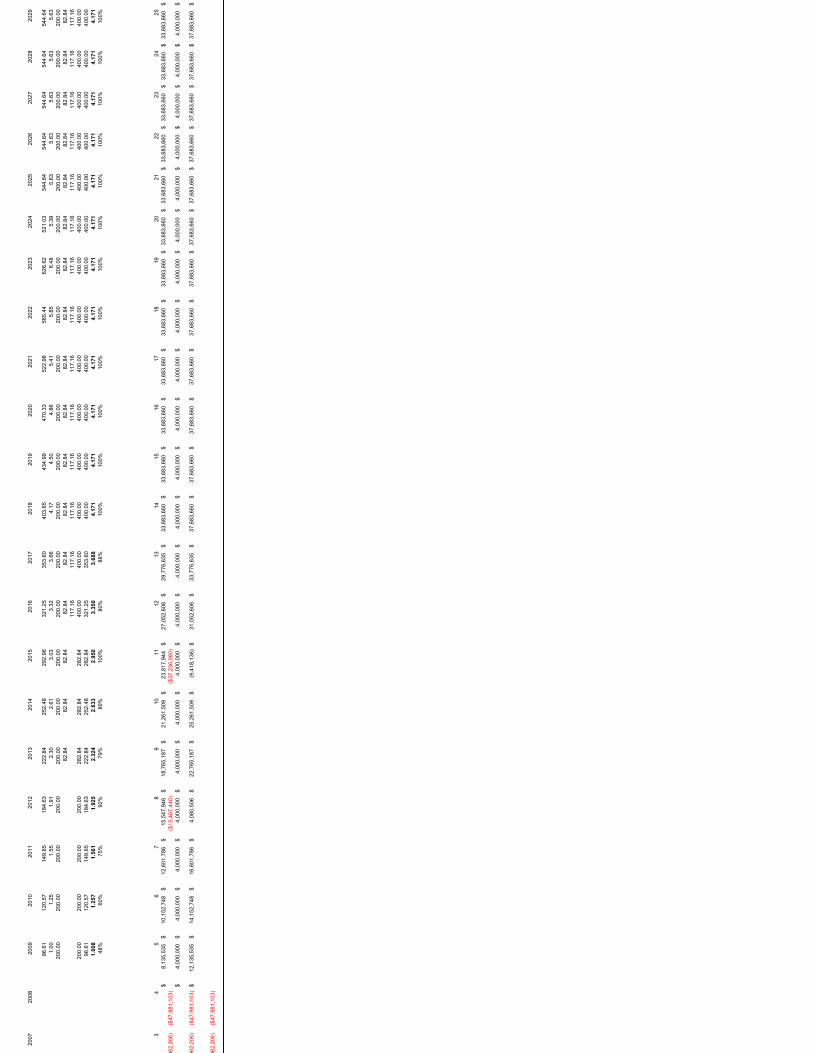
2007
2008
2009
2010
2011
2012
2013
2014
2015
2016
2017
2018
2019
2020
2021
2022
2023
2024
2025
2026
2027
2028
2029
96.6
112
0.57
149.
6518
4.63
222.
8425
2.48
292.
9632
1.25
353.
6040
3.65
434.
9947
0.33
522.
9856
5.44
626.
6252
1.03
544.
6454
4.64
544.
6454
4.64
544.
641.
001.
251.
551.
912.
302.
613.
033.
323.
664.
174.
504.
865.
415.
856.
485.
395.
635.
635.
635.
635.
6320
0.00
200.
0020
0.00
200.
0020
0.00
200.
0020
0.00
200.
0020
0.00
200.
0020
0.00
200.
0020
0.00
200.
0020
0.00
200.
0020
0.00
200.
0020
0.00
200.
0020
0.00
82.8
482
.84
82.8
482
.84
82.8
482
.84
82.8
482
.84
82.8
482
.84
82.8
482
.84
82.8
482
.84
82.8
482
.84
82.8
411
7.16
117.
1611
7.16
117.
1611
7.16
117.
1611
7.16
117.
1611
7.16
117.
1611
7.16
117.
1611
7.16
117.
1620
0.00
200.
0020
0.00
200.
0028
2.84
282.
8428
2.84
400.
0040
0.00
400.
0040
0.00
400.
0040
0.00
400.
0040
0.00
400.
0040
0.00
400.
0040
0.00
400.
0040
0.00
96.6
112
0.57
149.
6518
4.63
222.
8425
2.48
282.
8432
1.25
353.
6040
0.00
400.
0040
0.00
400.
0040
0.00
400.
0040
0.00
400.
0040
0.00
400.
0040
0.00
400.
001.
008
1.25
71.
561
1.92
52.
324
2.63
32.
950
3.35
03.
688
4.17
14.
171
4.17
14.
171
4.17
14.
171
4.17
14.
171
4.17
14.
171
4.17
14.
171
48%
60%
75%
92%
79%
89%
100%
80%
88%
100%
100%
100%
100%
100%
100%
100%
100%
100%
100%
100%
100%
34
56
78
910
1112
1314
1516
1718
1920
2122
2324
258,
135,
535
$
10,1
52,7
48$
12
,601
,786
$
15,5
47,9
46$
18
,765
,187
$
21,2
61,5
09$
23
,817
,944
$
27,0
52,6
06$
29
,776
,635
$
33,6
83,6
60$
33
,683
,660
$
33,6
83,6
60$
33
,683
,660
$
33,6
83,6
60$
33
,683
,660
$
33,6
83,6
60$
33
,683
,660
$
33,6
83,6
60$
33
,683
,660
$
33,6
83,6
60$
33
,683
,660
$
$
962,
206)
($47
,981
,103
)($
15,4
67,4
40)
($37
,236
,080
)4,
000,
000
$
4,00
0,00
0$
4,
000,
000
$
4,
000,
000
$
4,
000,
000
$
4,
000,
000
$
4,
000,
000
$
4,
000,
000
$
4,
000,
000
$
4,
000,
000
$
4,
000,
000
$
4,
000,
000
$
4,
000,
000
$
4,
000,
000
$
4,
000,
000
$
4,
000,
000
$
4,
000,
000
$
4,
000,
000
$
4,
000,
000
$
4,
000,
000
$
4,
000,
000
$
$
962,
206)
($47
,981
,103
)12
,135
,535
$
14,1
52,7
48$
16
,601
,786
$
4,08
0,50
6$
22,7
65,1
87$
25
,261
,509
$
(9,4
18,1
36)
$
31,0
52,6
06$
33
,776
,635
$
37,6
83,6
60$
37
,683
,660
$
37,6
83,6
60$
37
,683
,660
$
37,6
83,6
60$
37
,683
,660
$
37,6
83,6
60$
37
,683
,660
$
37,6
83,6
60$
37
,683
,660
$
37,6
83,6
60$
37
,683
,660
$
$
962,
206)
($47
,981
,103
)

Annex 6: Route Survey Results and Photographs
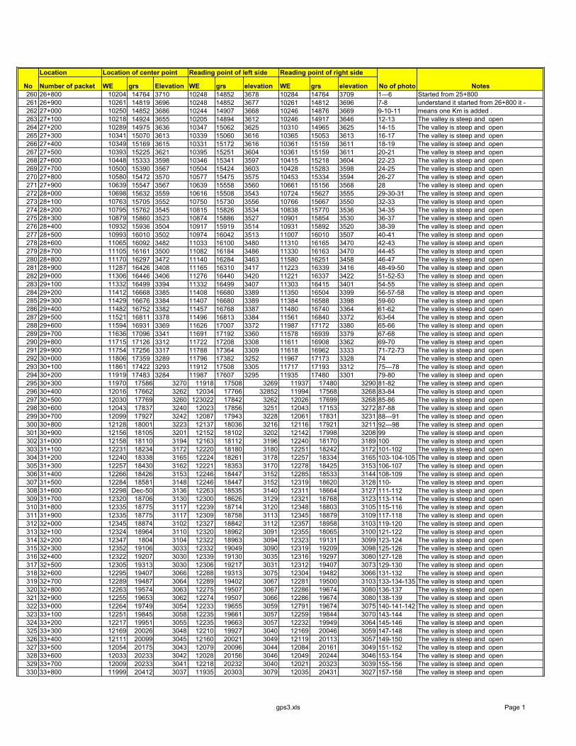
Location Location of center point Reading point of left side Reading point of right side
Number of packet WE grs Elevation WE grs elevation WE grs elevation260 26+800 10204 14764 3710 10248 14852 3678 10284 14764 3709 1---6 Started from 25+800 261 26+900 10261 14819 3696 10248 14852 3677 10261 14812 3696 7-8 understand it started from 26+800 it -262 27+000 10250 14852 3686 10244 14907 3668 10246 14876 3669 9-10-11 means one Km is added .263 27+100 10218 14924 3655 10205 14894 3612 10246 14917 3646 12-13 The valley is steep and open264 27+200 10289 14975 3636 10347 15062 3625 10310 14965 3625 14-15 The valley is steep and open265 27+300 10341 15070 3613 10339 15060 3616 10365 15053 3613 16-17 The valley is steep and open266 27+400 10349 15169 3615 10331 15172 3616 10361 15159 3611 18-19 The valley is steep and open267 27+500 10393 15225 3621 10395 15251 3604 10361 15159 3611 20-21 The valley is steep and open268 27+600 10448 15333 3598 10346 15341 3597 10415 15218 3604 22-23 The valley is steep and open269 27+700 10500 15390 3567 10504 15424 3603 10428 15283 3598 24-25 The valley is steep and open270 27+800 10580 15472 3570 10577 15475 3575 10453 15334 3594 26-27 The valley is steep and open271 27+900 10639 15547 3567 10639 15558 3560 10661 15156 3568 28 The valley is steep and open272 28+000 10698 15632 3559 10616 15508 3543 10724 15627 3555 29-30-31 The valley is steep and open273 28+100 10763 15705 3552 10750 15730 3556 10766 15667 3550 32-33 The valley is steep and open274 28+200 10795 15762 3545 10815 15826 3534 10838 15770 3536 34-35 The valley is steep and open275 28+300 10879 15860 3523 10874 15886 3527 10901 15854 3530 36-37 The valley is steep and open276 28+400 10932 15936 3504 10917 15919 3514 10931 15892 3520 38-39 The valley is steep and open277 28+500 10993 16010 3502 10974 16042 3513 11007 16010 3507 40-41 The valley is steep and open278 28+600 11065 16092 3482 11033 16100 3480 11310 16165 3470 42-43 The valley is steep and open279 28+700 11105 16161 3500 11082 16184 3486 11330 16163 3470 44-45 The valley is steep and open280 28+800 11170 16297 3472 11140 16284 3463 11580 16251 3458 46-47 The valley is steep and open281 28+900 11287 16426 3408 11165 16310 3417 11223 16339 3416 48-49-50 The valley is steep and open282 29+000 11306 16446 3406 11276 16440 3420 11221 16337 3422 51-52-53 The valley is steep and open283 29+100 11332 16499 3394 11332 16499 3407 11303 16415 3401 54-55 The valley is steep and open284 29+200 11412 16668 3385 11408 16680 3389 11350 16504 3399 56-57-58 The valley is steep and open285 29+300 11429 16676 3384 11407 16680 3389 11384 16588 3398 59-60 The valley is steep and open286 29+400 11482 16752 3382 11457 16768 3387 11480 16740 3364 61-62 The valley is steep and open287 29+500 11521 16811 3378 11496 16813 3384 11561 16840 3372 63-64 The valley is steep and open288 29+600 11594 16931 3369 11626 17007 3372 11987 17172 3380 65-66 The valley is steep and open289 29+700 11636 17096 3341 11691 17192 3360 11578 16939 3379 67-68 The valley is steep and open290 29+800 11715 17126 3312 11722 17208 3308 11611 16908 3362 69-70 The valley is steep and open291 29+900 11754 17256 3317 11788 17364 3309 11618 16962 3333 71-72-73 The valley is steep and open292 30+000 11806 17359 3289 11796 17382 3252 11967 17173 3328 74 The valley is steep and open293 30+100 11861 17422 3293 11912 17508 3305 11717 17193 3312 75---78 The valley is steep and open294 30+200 11919 17483 3284 11987 17607 3295 11935 17480 3301 79-80 The valley is steep and open295 30+300 11970 17586 3270 11918 17508 3269 11937 17480 3290 81-82 The valley is steep and open296 30+400 12016 17662 3262 12034 17766 32852 11994 17568 3268 83-84 The valley is steep and open297 30+500 12030 17769 3260 123022 17842 3262 12026 17699 3268 85-86 The valley is steep and open298 30+600 12043 17837 3240 12023 17856 3251 12043 17153 3272 87-88 The valley is steep and open299 30+700 12099 17927 3242 12087 17943 3228 12061 17831 3231 88---91 The valley is steep and open300 30+800 12128 18001 3223 12137 18036 3216 12116 17921 3211 92---98 The valley is steep and open301 30+900 12156 18105 3201 12152 18102 3202 12142 17998 3208 99 The valley is steep and open302 31+000 12158 18110 3194 12163 18112 3196 12240 18170 3189 100 The valley is steep and open303 31+100 12231 18234 3172 12220 18180 3180 12251 18242 3172 101-102 The valley is steep and open304 31+200 12240 18338 3165 12224 18261 3178 12257 18334 3165 103-104-105 The valley is steep and open305 31+300 12257 18430 3162 12221 18353 3170 12278 18425 3153 106-107 The valley is steep and open306 31+400 12266 18426 3153 12246 18447 3152 12285 18533 3144 108-109 The valley is steep and open307 31+500 12284 18581 3148 12246 18447 3152 12319 18620 3128 110- The valley is steep and open308 31+600 12298 Dec-50 3136 12263 18535 3140 12311 18664 3127 111-112 The valley is steep and open309 31+700 12320 18706 3130 12300 18626 3129 12321 18768 3123 113-114 The valley is steep and open310 31+800 12335 18775 3117 12239 18714 3120 12348 18803 3105 115-116 The valley is steep and open311 31+900 12335 18775 3117 12309 18758 3113 12345 18879 3109 117-118 The valley is steep and open312 32+000 12345 18874 3102 12327 18842 3112 12357 18958 3103 119-120 The valley is steep and open313 32+100 12324 18964 3110 12320 18962 3091 12355 18065 3100 121-122 The valley is steep and open314 32+200 12347 1804 3104 12322 18963 3094 12323 19131 3099 123-124 The valley is steep and open315 32+300 12352 19106 3033 12332 19049 3090 12319 19209 3098 125-126 The valley is steep and open316 32+400 12322 19207 3030 12339 19130 3035 12316 19297 3080 127-128 The valley is steep and open317 32+500 12305 19313 3030 12306 19217 3031 12312 19407 3073 129-130 The valley is steep and open318 32+600 12295 19407 3066 12288 19313 3075 12304 19482 3066 131-132 The valley is steep and open319 32+700 12289 19487 3064 12289 19402 3067 12281 19500 3103 133-134-135 The valley is steep and open320 32+800 12263 19574 3063 12275 19507 3067 12286 19674 3080 136-137 The valley is steep and open321 32+900 12255 19653 3062 12274 19507 3066 12286 19674 3080 138-139 The valley is steep and open322 33+000 12264 19749 3054 12233 19655 3059 12791 19674 3075 140-141-142 The valley is steep and open323 33+100 12251 19845 3058 12235 19661 3057 12259 19844 3070 143-144 The valley is steep and open324 33+200 12217 19951 3055 12235 19663 3057 12232 19949 3064 145-146 The valley is steep and open325 33+300 12169 20026 3048 12210 19927 3040 12169 20046 3059 147-148 The valley is steep and open326 33+400 12111 20099 3045 12160 20021 3049 12119 20113 3057 149-150 The valley is steep and open327 33+500 12054 20175 3043 12079 20096 3044 12084 20161 3049 151-152 The valley is steep and open328 33+600 12033 20233 3042 12028 20156 3046 12049 20244 3046 153-154 The valley is steep and open329 33+700 12009 20233 3041 12218 20232 3040 12021 20323 3039 155-156 The valley is steep and open330 33+800 11999 20412 3037 11935 20303 3079 12035 20431 3027 157-158 The valley is steep and open
No No of photo Notes
gps3.xls Page 1
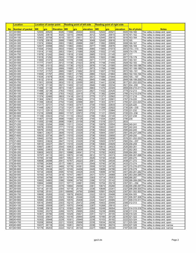
Location Location of center point Reading point of left side Reading point of right side
Number of packet WE grs Elevation WE grs elevation WE grs elevationNo No of photo Notes331 33+900 12005 20525 3026 11998 20444 3033 12022 20521 3020 159-160 The valley is steep and open332 34+000 12020 20619 3020 12015 20608 3012 12045 20615 3016 161-162 The valley is steep and open333 34+100 12063 20708 3019 12017 20611 3012 12045 20615 3016 163-164 The valley is steep and open334 34+200 11978 20816 2999 11985 20788 3049 12045 20616 3015 165 The valley is steep and open335 34+300 11974 20884 2993 11962 20886 2987 11992 20809 3008 166-167 The valley is steep and open336 34+400 12007 20998 2992 11960 20984 2977 11999 20876 2985 168-169 The valley is steep and open337 34+500 11934 21042 2933 11940 21089 2065 11945 21073 2972 170---173 The valley is steep and open338 34+600 11914 21165 2953 11941 21089 2926 11932 21145 3009 174-176 The valley is steep and open339 34+700 11878 21242 2940 11819 21309 2965 11915 21145 2971 177 The valley is steep and open340 34+800 11819 21292 2933 11799 21389 2935 11822 21386 2977 178-179 The valley is steep and open341 34+900 11800 21373 2928 11779 21448 2971 11777 21449 2941 180-181 The valley is steep and open342 35+000 11777 21447 2912 11736 21523 2876 11748 21494 2928 182-183 The valley is steep and open343 35+100 11756 21513 2902 11736 21523 2876 11734 21585 2905 184-185-186 The valley is steep and open344 35+200 11731 21622 2889 11695 21707 2873 11706 21686 2892 187-188-189 The valley is steep and open345 35+300 11707 21707 2865 11667 21692 2910 11657 21783 2872 190--191 The valley is steep and open346 35+400 11655 21797 2850 11651 21785 2880 11624 21864 2863 192-193-194 The valley is steep and open347 35+500 11634 21878 2839 11652 21785 2831 11585 21944 2850 195---197 The valley is steep and open348 35+600 11612 21914 2800 11565 21952 2845 11498 22055 2849 198-199-200 The valley is steep and open349 35+700 11501 22039 2832 11513 22055 2853 11441 22236 2817 201-202-203 The valley is steep and open350 35+800 11475 21130 2821 11493 22122 2846 11480 22234 2821 204--208 The valley is steep and open351 35+900 11488 21136 2873 11467 22224 2883 11470 22345 2859 209-210-211 The valley is steep and open352 36+000 11488 22136 2783 11503 22331 2827 11432 22420 2779 212-213 The valley is steep and open353 36+100 11488 22136 2783 11422 22415 2776 11382 22484 2766 214-215-216 The valley is steep and open354 36+200 11374 22460 2803 11418 22413 2775 11371 22562 2772 217-218 The valley is steep and open355 36+300 11364 22561 2753 11366 22564 2774 11357 22681 2767 219-220 The valley is steep and open356 36+400 11356 22634 2754 11345 22566 2691 11303 22761 2760 221-222-223 The valley is steep and open357 36+500 11317 22721 2742 11303 22747 2730 11553 22833 2733 225-225 The valley is steep and open358 36+600 11448 22821 2732 11247 22819 2720 11206 22922 2730 226---230 The valley is steep and open359 36+700 11211 22913 2722 11211 22965 2721 11177 22984 2720 231-232 The valley is steep and open360 36+800 11216 22908 2660 11157 22972 2705 11121 23045 2720 233--236 The valley is steep and open361 36+900 11109 23023 2702 11110 23022 2708 11064 23140 2757 237-238 The valley is steep and open362 37+00 11067 23104 2698 11050 23129 2745 11034 23264 2795 239 The valley is steep and open363 37+100 11055 23189 2698 11061 23159 2706 11016 23317 2833 The valley is steep and open364 37+200 11026 23294 2698 11011 23324 2736 10979 23554 2804 240-241 The valley is steep and open365 37+300 10978 23550 2771 11010 23329 2736 10932 23491 2597 242-243 The valley is steep and open366 37+400 10976 23353 2770 11010 23329 2736 10932 23503 2595 244-245 The valley is steep and open367 37+500 10961 23627 2809 11010 23329 2736 10944 23597 2581 246-247-248 The valley is steep and open368 37+600 10923 23734 2847 11010 23329 2736 10930 23650 2577 249-250 The valley is steep and open369 37+700 10940 23793 2847 11010 23329 2736 10932 23656 2576 251-252-253 The valley is steep and open370 37+800 10953 23824 2847 11010 23329 2736 10920 23767 2560 254---257 The valley is steep and open371 37+900 10910 24027 2847 11010 23329 2736 10840 23929 2529 258-259 The valley is steep and open372 38+000 10887 23861 2544 10953 23660 2774 10813 24023 2526 260-261 The valley is steep and open373 38+100 10856 23903 2516 10912 23939 2775 10766 24200 2513 262-263 The valley is steep and open374 38+200 10805 24023 2501 10886 24041 2774 10782 24283 2508 264-265 The valley is steep and open375 38+300 10797 24110 2491 10870 24146 2812 10772 24373 2482 266-267-268 The valley is steep and open376 38+400 10785 24168 2487 10822 24131 2626 10730 24538 2491 269-270 The valley is steep and open377 38+500 10808 24098 2541 10767 24223 2581 10750 24534 2438 271-272 The valley is steep and open378 38+600 10789 24384 2517 10801 24310 2549 10740 24726 2433 273-274 The valley is steep and open379 38+700 10748 24461 2465 10776 24381 2509 10720 24702 2427 275-276-277 The valley is steep and open380 38+800 10750 25538 2427 10745 24459 2449 10699 24790 2401 278-279 The valley is steep and open381 38+900 10734 24608 2595 10740 24529 2435 10699 24790 2401 280-281-282 The valley is steep and open382 39+000 10700 24703 2418 10747 24607 2431 10701 24968 2367 283-284-285 The valley is steep and open383 39+100 10700 24789 2391 10744 24599 2393 10714 25053 2369 286-287 The valley is steep and open384 39+200 10683 24883 2386 10696 24790 2396 10723 25142 2359 288-289-290 The valley is steep and open385 39+300 10884 24986 2331 10711 24961 2395 10704 25218 2357 291---294 The valley is steep and open386 39+400 10711 25045 2370 10694 25058 2361 10673 25280 2336 295-296-297 The valley is steep and open387 39+500 10714 25135 2354 10719 25130 2338 10648 23341 2327 298-299-300 The valley is steep and open388 39+600 10708 25181 2351 106956 24790 23580 10581 25425 2307 301-302-303 The valley is steep and open389 39+700 10669 25265 2332 10679 258292 2322 10515 25488 2306 304-305 The valley is steep and open390 39+800 10629 25355 2323 10636 25346 2328 10447 25521 2291 306-307-308 The valley is steep and open391 39+900 10580 25395 2305 10570 25408 2324 10447 25585 2317 309-310-311 The valley is steep and open392 40+000 10516 25465 2303 10210 25472 2306 10403 25494 2306 312-313 The valley is steep and open393 40+100 10449 25509 2297 10570 25408 2287 10268 25610 2301 The valley is steep and open394 40+200 10398 25616 2273 10393 25607 2269 10249 26054 2241 314-315-316 The valley is steep and open395 40+300 10392 25370 2269 10375 25695 2262 10239 26089 2238 317-318 The valley is steep and open396 40+400 10361 25780 2249 10329 25821 2251 10211 26105 2238 319-320 The valley is steep and open397 40+500 10333 25831 2252 10316 25844 2249 10160 26129 2235 321-322 The valley is steep and open398 40+600 10302 25948 2229 10301 25949 2239 10103 26192 2222 323-324 The valley is steep and open399 40+700 10209 26004 2221 10303 25958 2239 10034 26239 2211 325-326 The valley is steep and open400 40+800 10227 26116 2224 10261 26074 2238 10016 26274 2203 327-328 The valley is steep and narrow401 40+900 10178 26203 2222 10213 26130 2227 19964 26330 2187 329-330 The valley is steep and narrow
gps3.xls Page 2
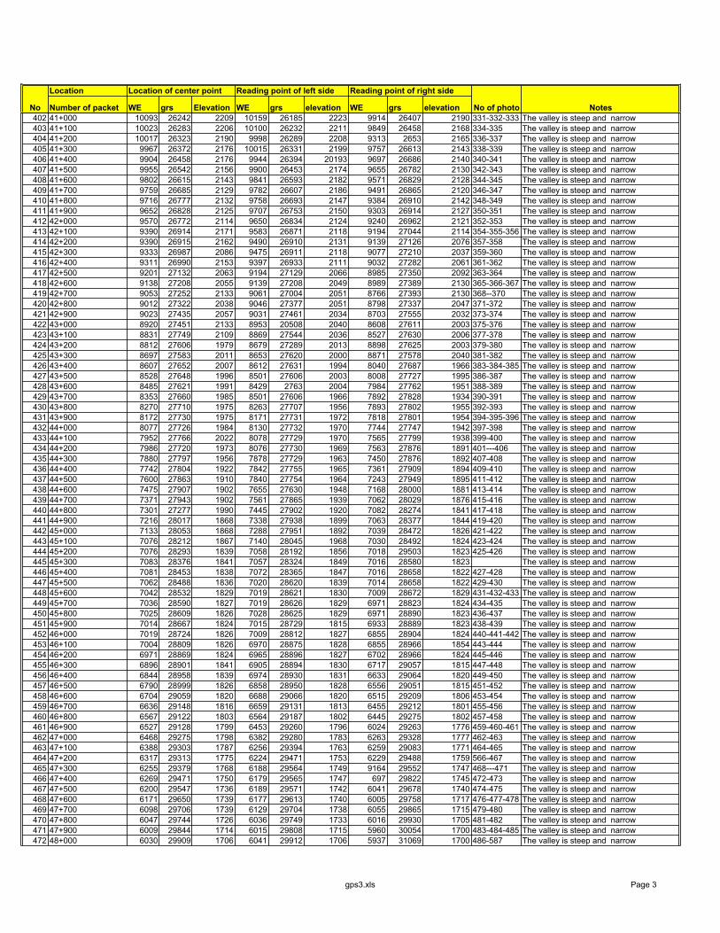
Location Location of center point Reading point of left side Reading point of right side
Number of packet WE grs Elevation WE grs elevation WE grs elevationNo No of photo Notes402 41+000 10093 26242 2209 10159 26185 2223 9914 26407 2190 331-332-333 The valley is steep and narrow403 41+100 10023 26283 2206 10100 26232 2211 9849 26458 2168 334-335 The valley is steep and narrow404 41+200 10017 26323 2190 9998 26289 2208 9313 2653 2165 336-337 The valley is steep and narrow405 41+300 9967 26372 2176 10015 26331 2199 9757 26613 2143 338-339 The valley is steep and narrow406 41+400 9904 26458 2176 9944 26394 20193 9697 26686 2140 340-341 The valley is steep and narrow407 41+500 9955 26542 2156 9900 26453 2174 9655 26782 2130 342-343 The valley is steep and narrow408 41+600 9802 26615 2143 9841 26593 2182 9571 26829 2128 344-345 The valley is steep and narrow409 41+700 9759 26685 2129 9782 26607 2186 9491 26865 2120 346-347 The valley is steep and narrow410 41+800 9716 26777 2132 9758 26693 2147 9384 26910 2142 348-349 The valley is steep and narrow411 41+900 9652 26828 2125 9707 26753 2150 9303 26914 2127 350-351 The valley is steep and narrow412 42+000 9570 26772 2114 9650 26834 2124 9240 26962 2121 352-353 The valley is steep and narrow413 42+100 9390 26914 2171 9583 26871 2118 9194 27044 2114 354-355-356 The valley is steep and narrow414 42+200 9390 26915 2162 9490 26910 2131 9139 27126 2076 357-358 The valley is steep and narrow415 42+300 9333 26987 2086 9475 26911 2118 9077 27210 2037 359-360 The valley is steep and narrow416 42+400 9311 26990 2153 9397 26933 2111 9032 27282 2061 361-362 The valley is steep and narrow417 42+500 9201 27132 2063 9194 27129 2066 8985 27350 2092 363-364 The valley is steep and narrow418 42+600 9138 27208 2055 9139 27208 2049 8989 27389 2130 365-366-367 The valley is steep and narrow419 42+700 9053 27252 2133 9061 27004 2051 8766 27393 2130 368--370 The valley is steep and narrow420 42+800 9012 27322 2038 9046 27377 2051 8798 27337 2047 371-372 The valley is steep and narrow421 42+900 9023 27435 2057 9031 27461 2034 8703 27555 2032 373-374 The valley is steep and narrow422 43+000 8920 27451 2133 8953 20508 2040 8608 27611 2003 375-376 The valley is steep and narrow423 43+100 8831 27749 2109 8869 27544 2036 8527 27630 2006 377-378 The valley is steep and narrow424 43+200 8812 27606 1979 8679 27289 2013 8898 27625 2003 379-380 The valley is steep and narrow425 43+300 8697 27583 2011 8653 27620 2000 8871 27578 2040 381-382 The valley is steep and narrow426 43+400 8607 27652 2007 8612 27631 1994 8040 27687 1966 383-384-385 The valley is steep and narrow427 43+500 8528 27648 1996 8501 27606 2003 8008 27727 1995 386-387 The valley is steep and narrow428 43+600 8485 27621 1991 8429 2763 2004 7984 27762 1951 388-389 The valley is steep and narrow429 43+700 8353 27660 1985 8501 27606 1966 7892 27828 1934 390-391 The valley is steep and narrow430 43+800 8270 27710 1975 8263 27707 1956 7893 27802 1955 392-393 The valley is steep and narrow431 43+900 8172 27730 1975 8171 27731 1972 7818 27801 1954 394-395-396 The valley is steep and narrow432 44+000 8077 27726 1984 8130 27732 1970 7744 27747 1942 397-398 The valley is steep and narrow433 44+100 7952 27766 2022 8078 27729 1970 7565 27799 1938 399-400 The valley is steep and narrow434 44+200 7986 27720 1973 8076 27730 1969 7563 27876 1891 401---406 The valley is steep and narrow435 44+300 7880 27797 1956 7878 27729 1963 7450 27876 1892 407-408 The valley is steep and narrow436 44+400 7742 27804 1922 7842 27755 1965 7361 27909 1894 409-410 The valley is steep and narrow437 44+500 7600 27863 1910 7840 27754 1964 7243 27949 1895 411-412 The valley is steep and narrow438 44+600 7475 27907 1902 7655 27630 1948 7168 28000 1881 413-414 The valley is steep and narrow439 44+700 7371 27943 1902 7561 27865 1939 7062 28029 1876 415-416 The valley is steep and narrow440 44+800 7301 27277 1990 7445 27902 1920 7082 28274 1841 417-418 The valley is steep and narrow441 44+900 7216 28017 1868 7338 27938 1899 7063 28377 1844 419-420 The valley is steep and narrow442 45+000 7133 28053 1868 7288 27951 1892 7039 28472 1826 421-422 The valley is steep and narrow443 45+100 7076 28212 1867 7140 28045 1968 7030 28492 1824 423-424 The valley is steep and narrow444 45+200 7076 28293 1839 7058 28192 1856 7018 29503 1823 425-426 The valley is steep and narrow445 45+300 7083 28376 1841 7057 28324 1849 7016 28580 1823 The valley is steep and narrow446 45+400 7081 28453 1838 7072 28365 1847 7016 28658 1822 427-428 The valley is steep and narrow447 45+500 7062 28488 1836 7020 28620 1839 7014 28658 1822 429-430 The valley is steep and narrow448 45+600 7042 28532 1829 7019 28621 1830 7009 28672 1829 431-432-433 The valley is steep and narrow449 45+700 7036 28590 1827 7019 28626 1829 6971 28823 1824 434-435 The valley is steep and narrow450 45+800 7025 28609 1826 7028 28625 1829 6971 28890 1823 436-437 The valley is steep and narrow451 45+900 7014 28667 1824 7015 28729 1815 6933 28889 1823 438-439 The valley is steep and narrow452 46+000 7019 28724 1826 7009 28812 1827 6855 28904 1824 440-441-442 The valley is steep and narrow453 46+100 7004 28809 1826 6970 28875 1828 6855 28966 1854 443-444 The valley is steep and narrow454 46+200 6971 28869 1824 6965 28896 1827 6702 28966 1824 445-446 The valley is steep and narrow455 46+300 6896 28901 1841 6905 28894 1830 6717 29057 1815 447-448 The valley is steep and narrow456 46+400 6844 28958 1839 6974 28930 1831 6633 29064 1820 449-450 The valley is steep and narrow457 46+500 6790 28999 1826 6858 28950 1828 6556 29051 1815 451-452 The valley is steep and narrow458 46+600 6704 29059 1820 6688 29066 1820 6515 29209 1806 453-454 The valley is steep and narrow459 46+700 6636 29148 1816 6659 29131 1813 6455 29212 1801 455-456 The valley is steep and narrow460 46+800 6567 29122 1803 6564 29187 1802 6445 29275 1802 457-458 The valley is steep and narrow461 46+900 6527 29128 1799 6453 29260 1796 6024 29263 1776 459-460-461 The valley is steep and narrow462 47+000 6468 29275 1798 6382 29280 1783 6263 29328 1777 462-463 The valley is steep and narrow463 47+100 6388 29303 1787 6256 29394 1763 6259 29083 1771 464-465 The valley is steep and narrow464 47+200 6317 29313 1775 6224 29471 1753 6229 29488 1759 566-467 The valley is steep and narrow465 47+300 6255 29379 1768 6188 29564 1749 9164 29552 1747 468---471 The valley is steep and narrow466 47+400 6269 29471 1750 6179 29565 1747 697 29822 1745 472-473 The valley is steep and narrow467 47+500 6200 29547 1736 6189 29571 1742 6041 29678 1740 474-475 The valley is steep and narrow468 47+600 6171 29650 1739 6177 29613 1740 6005 29758 1717 476-477-478 The valley is steep and narrow469 47+700 6098 29706 1739 6129 29704 1738 6055 29865 1715 479-480 The valley is steep and narrow470 47+800 6047 29744 1726 6036 29749 1733 6016 29930 1705 481-482 The valley is steep and narrow471 47+900 6009 29844 1714 6015 29808 1715 5960 30054 1700 483-484-485 The valley is steep and narrow472 48+000 6030 29909 1706 6041 29912 1706 5937 31069 1700 486-587 The valley is steep and narrow
gps3.xls Page 3

Location Location of center point Reading point of left side Reading point of right side
Number of packet WE grs Elevation WE grs elevation WE grs elevationNo No of photo Notes473 48+100 6052 29960 1699 6070 29995 1703 5903 30223 1699 488-489 The valley is steep and narrow474 48+200 6046 30035 1698 6024 30066 1701 5931 30304 1697 490-491 The valley is steep and narrow475 48+300 5985 30155 1698 5980 30171 1698 5774 30386 1684 492-493 The valley is steep and narrow476 48+400 5947 30288 1694 5958 30221 1696 5719 30453 1669 494-495 The valley is steep and narrow477 48+500 5913 30281 1688 5930 30265 1693 5676 30531 1674 496-497 The valley is steep and narrow478 48+600 5843 30371 1687 5854 30391 1685 5634 30594 1672 498-499 The valley is steep and narrow479 48+700 5784 30444 1683 5781 30454 1673 5536 30662 1663 500-501 The valley is steep and narrow480 48+800 5743 30497 1647 5737 30515 1672 5541 30814 1662 502-503 The valley is steep and narrow481 48+900 5680 30605 1682 5684 30588 1667 5524 30897 1642 504-505 The valley is steep and narrow482 49+000 5639 30656 1676 5634 30657 1664 5478 30982 1652 506 The valley is steep and narrow483 49+100 5572 30751 1676 5577 30725 1661 5422 31037 1652 507-508 The valley is steep and narrow484 49+200 5561 30797 1664 5534 30802 1659 5386 31089 1651 509-510 The valley is steep and narrow485 49+300 5543 30897 1659 5516 30916 1659 5386 31199 1636 511-512-513 The valley is steep and narrow486 49+400 5522 30995 1651 5502 30997 1655 5339 31199 1636 514-515 The valley is steep and narrow487 49+500 5480 31034 1653 5461 31082 1647 5274 31266 1637 516-517 The valley is steep and narrow488 49+600 5440 31086 1652 5434 31143 1654 5240 31332 1625 518-519 The valley is steep and narrow489 49+700 5392 31205 1645 5368 31205 1643 5187 31402 1612 520 The valley is steep and narrow490 49+800 5343 31265 1642 5335 31272 1628 5096 31460 1623 521 The valley is steep and narrow491 49+900 5216 31450 1632 5227 31408 1626 5088 31617 1626 522-523 The valley is steep and narrow492 50+000 5215 31443 1632 5251 31420 1606 5045 31639 1613 524-525 The valley is steep and narrow493 50+100 5174 31493 1630 5180 31469 1609 5025 31732 1604 526-527 The valley is steep and narrow494 50+200 5138 31854 1628 5143 31551 1610 4987 31784 1604 528-529 The valley is steep and narrow495 50+300 5099 31629 1611 5095 31634 1609 4922 31870 1599 530-531 The valley is steep and narrow496 50+400 5033 31739 1611 5043 31712 1605 4877 31925 1595 532-533 The valley is steep and narrow497 50+500 5016 31799 1600 5011 31801 1599 4817 31978 1584 534-535 The valley is steep and narrow498 50+600 4960 31871 1598 4964 31884 1598 4737 32059 1578 The valley is steep and narrow499 50+700 4928 31919 1596 4905 31931 1600 4656 32128 1576 536-537 The valley is steep and narrow500 50+800 4845 31998 1592 4843 31995 1588 4991 32162 1573 538-539 The valley is steep and narrow501 50+900 4790 32067 1588 4796 32060 1583 4533 32198 1567 540-541-542 The valley is steep and narrow502 51+000 4731 32122 1589 4724 32125 1583 4471 32260 1561 543-544 The valley is steep and narrow503 51+100 4635 32157 1594 4648 32168 1568 4381 32311 1562 545---548 The valley is steep and narrow504 51+200 4578 32208 1585 4573 32202 1583 4384 32413 1556 549-550 The valley is steep and narrow505 51+300 4508 32266 1568 4511 32264 1568 4359 32470 1549 551-552 The valley is steep and narrow506 51+400 4449 32324 1569 4450 32331 1557 4317 3256 1551 553-554 The valley is steep and narrow507 51+500 4379 32394 1566 4385 32395 1557 4319 32685 1544 555 The valley is steep and narrow508 51+600 4346 32474 1552 4353 32467 1557 4281 32776 1540 556-557 The valley is steep and narrow509 51+700 4390 32568 1552 4366 32577 1546 4206 32829 1537 558-559 The valley is steep and narrow510 51+800 4343 32644 1550 4342 32636 1552 4094 32905 1540 560-561-562 The valley is steep and narrow511 51+900 4328 32707 1551 4292 32811 1541 4025 33018 1538 563 The valley is steep and narrow512 52+000 4299 32797 1551 4205 32907 1534 4008 33059 1532 564-656-566 The valley is steep and narrow513 52+100 4206 32905 1546 4198 32915 1535 3949 33051 1536 567-568 The valley is steep and narrow514 52+200 4148 32948 1535 4142 32957 1540 3947 33090 1531 569-570 The valley is steep and narrow515 52+300 4099 33014 1537 4089 33025 1546 3867 33153 1530 571-572 The valley is steep and narrow516 52+400 4022 33046 1541 4022 33061 1538 3850 33230 1513 573-574 The valley is steep and narrow517 52+500 3959 33103 1539 3959 33101 1515 3855 33310 1509 575-576 The valley is steep and narrow518 52+600 3941 33159 1537 3919 33169 1528 3899 33397 1506 577-578 The valley is steep and narrow519 52+700 3877 33203 1523 3875 33231 1528 3973 33432 1508 579-580 The valley is steep and narrow520 52+800 3858 33248 1519 3441 33323 1525 3973 33535 1470 581-582 The valley is steep and narrow521 52+900 3855 33395 1504 3869 33369 1527 3938 33636 1485 583-584 The valley is steep and narrow522 53+000 3900 33471 1488 3902 33446 1507 3938 33641 1448 585-586 The valley is steep and narrow523 53+100 3929 33545 1500 3927 33551 1493 3947 33641 1448 587-588 The valley is steep and narrow524 53+200 3945 33645 1489 3936 33615 1484 3947 33875 1428 589-590 The valley is steep and narrow525 53+300 3931 33726 1493 3915 33738 1482 3947 33875 1428 591-592 The valley is steep and narrow526 53+400 3935 33736 1455 3964 33828 1472 3947 33875 1428 593-594 The valley is steep and narrow527 53+500 3935 33997 1475 3942 33909 1471 4005 33875 1428 595-596 The valley is steep and narrow528 53+600 3954 34069 1446 3964 33977 1468 4016 34256 1423 597-598 The valley is steep and narrow529 53+700 3930 34158 1409 3964 34067 1466 4018 34292 1419 599-600 The valley is steep and narrow530 53+800 3957 34158 1413 3956 34158 1401 3951 34411 1434 601-602 The valley is steep and narrow531 53+900 4010 34294 1449 3986 34241 1407 3911 34502 1424 603-604 The valley is steep and narrow532 54+000 4016 34371 1450 4006 34326 1453 3911 34538 1429 605-606 The valley is steep and narrow533 54+100 3959 34481 1452 4027 34398 1448 3882 34539 1411 607-608 The valley is steep and narrow534 54+200 3908 34540 1438 3982 34451 1444 3886 34588 1429 609-610 The valley is steep and narrow535 54+300 3882 34608 1437 3869 34609 1436 3821 34781 1416 611-612 The valley is steep and narrow536 54+400 3879 34710 1439 3868 34611 1436 3784 34935 1410 613-614 The valley is steep and narrow537 54+500 3864 34761 1432 3872 34696 1432 3766 35012 1405 615-616 The valley is steep and narrow538 54+600 3821 34879 1430 3838 34776 1429 3710 35093 1409 617-618 The valley is steep and narrow539 54+700 3773 35018 1428 3822 34924 1424 3647 35182 1405 619-620 The valley is steep and narrow540 54+800 3748 35073 1422 3777 35013 1421 3641 35259 1412 621-622 The valley is steep and narrow541 54+900 3701 35183 1411 3744 35104 1413 3582 35257 1384 623-624 The valley is steep and narrow542 55+000 3658 35267 1407 3697 35181 1411 3510 35385 1403 625--628 The valley is steep and narrow543 55+100 3598 35328 1404 3660 35238 1418 3486 35335 1402 629-630 The valley is steep and narrow
gps3.xls Page 4
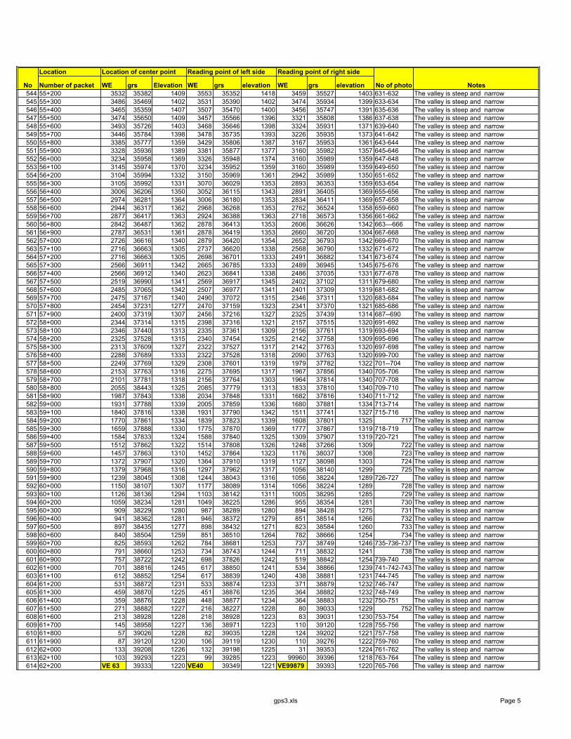
Location Location of center point Reading point of left side Reading point of right side
Number of packet WE grs Elevation WE grs elevation WE grs elevationNo No of photo Notes544 55+200 3532 35382 1409 3553 35352 1418 3459 35527 1403 631-632 The valley is steep and narrow545 55+300 3486 35469 1402 3531 35390 1402 3474 35934 1399 633-634 The valley is steep and narrow546 55+400 3465 35359 1407 3507 35470 1400 3456 35747 1391 635-636 The valley is steep and narrow547 55+500 3474 35650 1409 3457 35566 1396 3321 35808 1386 637-638 The valley is steep and narrow548 55+600 3493 35726 1403 3468 35646 1398 3324 35931 1371 639-640 The valley is steep and narrow549 55+700 3446 35784 1398 3478 35735 1393 3226 35935 1373 641-642 The valley is steep and narrow550 55+800 3385 35777 1359 3429 35806 1387 3167 35953 1361 643-644 The valley is steep and narrow551 55+900 3328 35936 1389 3381 35877 1377 3160 35982 1357 645-646 The valley is steep and narrow552 56+000 3234 35958 1369 3326 35948 1374 3160 35989 1359 647-648 The valley is steep and narrow553 56+100 3145 35974 1370 3234 35952 1359 3160 35989 1359 649-650 The valley is steep and narrow554 56+200 3104 35994 1332 3150 35969 1361 2942 35989 1350 651-652 The valley is steep and narrow555 56+300 3105 35992 1331 3070 36029 1353 2893 36353 1359 653-654 The valley is steep and narrow556 56+400 3006 36206 1350 3052 36115 1343 2891 36405 1369 655-656 The valley is steep and narrow557 56+500 2974 36281 1364 3006 36180 1353 2834 36411 1369 657-658 The valley is steep and narrow558 56+600 2944 36317 1362 2968 36268 1353 2762 36524 1358 659-660 The valley is steep and narrow559 56+700 2877 36417 1363 2924 36388 1363 2718 36573 1356 661-662 The valley is steep and narrow560 56+800 2842 36487 1362 2878 36413 1353 2606 36626 1342 663---666 The valley is steep and narrow561 56+900 2787 36531 1361 2878 36419 1353 2660 36720 1304 667-668 The valley is steep and narrow562 57+000 2726 36616 1340 2879 36420 1354 2652 36793 1342 669-670 The valley is steep and narrow563 57+100 2716 36663 1305 2737 36620 1338 2568 36790 1332 671-672 The valley is steep and narrow564 57+200 2716 36663 1305 2698 36701 1333 2491 36882 1341 673-674 The valley is steep and narrow565 57+300 2566 36911 1342 2665 36785 1333 2489 36945 1345 675-676 The valley is steep and narrow566 57+400 2566 36912 1340 2623 36841 1338 2486 37035 1331 677-678 The valley is steep and narrow567 57+500 2519 36990 1341 2569 36917 1345 2402 37102 1311 679-680 The valley is steep and narrow568 57+600 2485 37065 1342 2507 36977 1341 2401 37309 1319 681-682 The valley is steep and narrow569 57+700 2475 37167 1340 2490 37072 1315 2346 37311 1320 683-684 The valley is steep and narrow570 57+800 2454 37231 1277 2470 37159 1323 2341 37370 1321 685-686 The valley is steep and narrow571 57+900 2400 37319 1307 2456 37216 1327 2325 37439 1314 687--690 The valley is steep and narrow572 58+000 2344 37314 1315 2398 37316 1321 2157 37515 1320 691-692 The valley is steep and narrow573 58+100 2346 37440 1313 2335 37361 1309 2156 37761 1319 693-694 The valley is steep and narrow574 58+200 2325 37528 1315 2340 37454 1325 2142 37758 1309 695-696 The valley is steep and narrow575 58+300 2313 37609 1327 2322 37527 1317 2142 37763 1320 697-698 The valley is steep and narrow576 58+400 2288 37689 1333 2322 37528 1318 2090 37763 1320 699-700 The valley is steep and narrow577 58+500 2249 37769 1329 2308 37601 1319 1979 37782 1322 701--704 The valley is steep and narrow578 58+600 2153 37763 1316 2275 37695 1317 1967 37856 1340 705-706 The valley is steep and narrow579 58+700 2101 37781 1318 2156 37764 1303 1964 37814 1340 707-708 The valley is steep and narrow580 58+800 2055 38443 1325 2085 37779 1313 1833 37810 1340 709-710 The valley is steep and narrow581 58+900 1987 37843 1338 2034 37848 1331 1682 37816 1340 711-712 The valley is steep and narrow582 59+000 1931 37788 1339 2005 37859 1336 1680 37881 1334 713-714 The valley is steep and narrow583 59+100 1840 37816 1338 1931 37790 1342 1511 37741 1327 715-716 The valley is steep and narrow584 59+200 1770 37861 1334 1839 37823 1339 1608 37801 1325 717 The valley is steep and narrow585 59+300 1659 37888 1330 1775 37870 1369 1777 37867 1319 718-719 The valley is steep and narrow586 59+400 1584 37833 1324 1588 37840 1325 1309 37907 1319 720-721 The valley is steep and narrow587 59+500 1512 37862 1322 1514 37808 1326 1248 37266 1309 722 The valley is steep and narrow588 59+600 1457 37863 1310 1452 37864 1323 1176 38037 1308 723 The valley is steep and narrow589 59+700 1372 37907 1320 1364 37910 1319 1127 38098 1303 724 The valley is steep and narrow590 59+800 1379 37968 1316 1297 37962 1317 1056 38140 1299 725 The valley is steep and narrow591 59+900 1239 38045 1308 1244 38043 1316 1056 38224 1289 726-727 The valley is steep and narrow592 60+000 1150 38107 1307 1177 38089 1314 1056 38224 1289 728 The valley is steep and narrow593 60+100 1126 38136 1294 1103 38142 1311 1005 38295 1285 729 The valley is steep and narrow594 60+200 1059 38234 1281 1049 38225 1286 955 38354 1281 730 The valley is steep and narrow595 60+300 909 38229 1280 987 38289 1280 894 38428 1275 731 The valley is steep and narrow596 60+400 941 38362 1281 946 38372 1279 851 38514 1266 732 The valley is steep and narrow597 60+500 897 38435 1277 898 38432 1271 823 38584 1260 733 The valley is steep and narrow598 60+600 840 38504 1259 851 38510 1264 782 38666 1254 734 The valley is steep and narrow599 60+700 825 38593 1262 784 38681 1253 737 38749 1246 735-736-737 The valley is steep and narrow600 60+800 791 38660 1253 734 38743 1244 711 38832 1241 738 The valley is steep and narrow601 60+900 757 38722 1242 698 37826 1242 519 38842 1254 739-740 The valley is steep and narrow602 61+000 701 38816 1245 617 38850 1241 534 38866 1239 741-742-743 The valley is steep and narrow603 61+100 612 38852 1254 617 38839 1240 438 38881 1231 744-745 The valley is steep and narrow604 61+200 531 38872 1231 533 38874 1233 371 38879 1232 746-747 The valley is steep and narrow605 61+300 459 38870 1225 451 38876 1235 364 38882 1232 748-749 The valley is steep and narrow606 61+400 359 38876 1228 448 38877 1234 364 38883 1232 750-751 The valley is steep and narrow607 61+500 271 38882 1227 216 38227 1228 80 39033 1229 752 The valley is steep and narrow608 61+600 213 38928 1228 218 38928 1223 83 39031 1230 753-754 The valley is steep and narrow609 61+700 145 38958 1227 136 38971 1223 110 39120 1228 755-756 The valley is steep and narrow610 61+800 57 39026 1228 82 39035 1228 124 39202 1221 757-758 The valley is steep and narrow611 61+900 87 39120 1230 106 39119 1230 110 39276 1222 759-760 The valley is steep and narrow612 62+000 133 39208 1226 132 39198 1225 31 39353 1224 761-762 The valley is steep and narrow613 62+100 103 39293 1223 99 39285 1223 99960 39396 1218 763-764 The valley is steep and narrow614 62+200 VE 63 39333 1220 VE40 39349 1221 VE99879 39393 1220 765-766 The valley is steep and narrow
gps3.xls Page 5

Location Location of center point Reading point of left side Reading point of right side
Number of packet WE grs Elevation WE grs elevation WE grs elevationNo No of photo Notes615 62+300 99203 39647 1177 99150 40341 1242 99785 39406 1218 767 The valley is steep and narrow616 62+400 99207 39207 1180 99161 40419 1252 99684 39388 1217 768-769 The valley is steep and narrow617 62+500 99221 39778 1185 99188 40502 1261 99585 39399 1214 770-771 The valley is steep and narrow618 62+600 99212 39877 1204 99210 40585 1269 99502 39405 1213 772--774- The valley is steep and narrow619 62+700 99196 39947 1202 99252 40652 1277 99526 39399 1175 775 The valley is steep and narrow620 62+800 99189 40026 1206 99290 40712 1289 99355 39418 1208 776 The valley is steep and narrow621 62+900 99136 40095 1219 99332 40768 1303 99214 39478 1190 777 -780 The valley is steep and narrow622 63+000 99180 40175 1225 99381 40858 1321 99214 39477 1189 The valley is steep and narrow623 63+100 99151 40248 1229 99433 40925 1320 99186 39598 1288 781 The valley is steep and narrow624 63+200 99451 40983 1307 99456 40997 1327 92223 39648 1179 782-783 The valley is steep and narrow625 63+300 99451 41090 1323 99452 41080 1330 99218 39708 1187 784--786 The valley is steep and narrow626 63+400 99465 41125 1323 99468 41119 1335 99218 39775 1196 787-788 The valley is steep and narrow627 63+500 99479 41152 1325 99473 41157 1339 99204 39857 1201 789-790 The valley is steep and narrow628 63+600 99490 41187 1326 99497 41196 1341 99207 39867 1202 791 The valley is steep and narrow629 63+700 99525 41209 1327 99524 41228 1344 99196 40049 1219 792 The valley is steep and narrow630 63+800 99574 41290 1355 99574 41294 1355 99182 40163 1229 793 The valley is steep and narrow631 63+900 99611 41365 1366 99615 41365 1360 99150 40334 1245 794 The valley is steep and narrow632 64+000 99662 41422 1327 99657 41419 1368 99165 40411 1259 795 The valley is steep and narrow633 64+100 99693 41478 1370 99697 41494 1380 99186 40496 1264 796-797 The valley is steep and narrow634 64+200 99752 41559 1385 99749 41573 1389 99209 40567 1269 798 The valley is steep and narrow635 64+300 99781 41642 1405 99779 41634 1401 99249 40644 1277 799-800 The valley is steep and narrow636 64+400 99788 41722 1423 99767 41810 1436 99294 40712 1288 801-802 The valley is steep and narrow637 64+500 99767 41798 1429 99737 41886 1434 99336 40778 1306 803 The valley is steep and narrow638 64+600 99738 41880 1433 99707 41962 1444 99379 40856 1314 804 The valley is steep and narrow639 64+700 99722 41955 1445 99677 42025 1455 99428 40921 1318 805 The valley is steep and narrow640 64+800 99681 42030 1445 99672 42018 1456 99454 40994 1328 806 The valley is steep and narrow641 64+900 99627 42104 1466 99674 42094 1472 99457 41085 1338 807 The valley is steep and narrow642 65+000 99619 42136 1489 99611 42148 1490 99454 41083 1335 808-809 The valley is steep and narrow643 65+100 99605 42262 1498 99594 42237 1504 99486 41185 1339 810 The valley is steep and narrow644 65+200 99580 42323 1504 99571 42329 1503 99525 41228 1348 811-812 The valley is steep and narrow645 65+300 99574 42415 1507 99569 42401 1510 99527 41235 1351 813-814 The valley is passable and narrow646 65+400 99582 42493 1520 99564 42489 1522 99568 41292 1331 815-816 The valley is passable and narrow647 65+500 99602 42553 1525 99592 42570 1532 99616 41367 1367 817 The valley is passable and narrow648 65+600 99624 42624 1539 99605 42640 1540 99661 41430 1369 818-819 The valley is passable and narrow649 65+700 99564 42640 1555 99556 42646 1552 99694 41481 1375 820-821 The valley is passable and narrow650 65+800 99534 42649 1564 99543 42681 1570 99740 41550 1395 822 The valley is passable and narrow651 65+900 99563 42733 1607 99566 42740 1607 99785 41662 1410 823 The valley is passable and narrow652 66+000 99615 42776 1604 99608 42779 1597 99780 41727 1424 824-825 The valley is passable and narrow653 66+100 99645 42824 1604 99634 42896 1587 99764 41815 1430 826 The valley is passable and narrow654 66+200 99641 42889 1588 99639 42950 1587 99765 41815 1430 827 The valley is passable and narrow655 66+300 99634 42955 1586 99619 43016 1587 99739 41891 1435 828 The valley is passable and narrow656 66+400 99631 42010 1586 99639 43055 1588 99723 41958 1447 829-830 The valley is passable and narrow657 66+500 99639 43057 1586 99639 43053 1588 99650 42104 1474 831 The valley is passable and narrow658 66+600 99727 43109 1598 99663 43087 1611 99616 42147 1493 832-833 The valley is passable and narrow659 66+700 99727 43109 1548 99694 43200 1622 99597 42235 1508 834 The valley is passable and narrow660 66+800 99727 43109 1632 99702 43210 1614 99594 42276 1507 835 The valley is passable and narrow661 66+900 99727 43109 1648 99745 43489 1652 99574 42409 1545 836-837 The valley is passable and narrow662 67+000 99727 43109 1688 99745 43486 1652 99576 42498 1525 838-839 The valley is passable and narrow663 67+100 99737 43432 1720 99697 43497 1689 99594 42561 1534 840 The valley is passable and narrow664 67+200 99698 43495 1721 99696 43495 1744 99605 42634 1536 841 The valley is passable and narrow665 67+300 99689 43560 1729 99689 43565 1753 99549 42625 1577 842-843-844 The valley is passable and narrow666 67+400 99701 43636 1741 99702 43615 1769 99539 42673 1585 845-846 The valley is passable and narrow667 67+500 99734 43690 1744 99753 43657 1774 99582 42725 1622 847 The valley is passable and narrow668 67+600 99735 43692 1800 99760 43720 1780 99649 42887 1647 848 The valley is passable and narrow669 67+700 99759 43729 1817 99798 43783 1786 99682 42826 1647 849-850 The valley is passable and narrow670 67+800 99805 43802 1824 99825 43848 1790 99620 43017 1684 851-852 The valley is passable and narrow671 67+900 99825 43829 1840 99825 43849 1790 99616 43032 1684 853-853 The valley is passable and narrow672 68+000 99792 43872 1845 99768 43843 1816 99616 43032 1684 854-855 The valley is passable and narrow673 68+100 99795 43891 1868 99764 43838 1823 99589 43184 1722 856-857 The valley is passable and narrow674 68+200 99798 43895 1872 99764 43839 1824 99610 43208 1722 858-859 The valley is passable and narrow675 68+300 99809 43923 1858 99780 43876 1885 99622 43245 1722 860-861 The valley is passable and narrow676 68+400 99810 43934 1891 99800 43930 1890 99623 43245 1684 862---865 The valley is passable and narrow677 68+500 99801 43944 1895 99774 43926 1895 99623 43245 1684 866-867 The valley is passable and narrow678 68+600 99828 43962 1905 99790 43984 1910 99623 43245 1744 868-869 The valley is passable and narrow679 68+700 99796 43989 1932 99790 43984 1925 99693 43464 1766 870-872 The valley is passable and narrow680 68+800 99736 43992 1959 99735 43997 1955 99693 43487 1767 871 The valley is passable and narrow681 68+900 99722 44019 1989 99718 44012 1975 99683 43528 1787 873-874 The valley is passable and narrow682 69+000 99697 44030 1984 99686 44021 1978 99684 43554 1768 875 The valley is passable and narrow683 69+100 99656 44058 1983 99655 44057 1979 99700 43627 1789 876-877 The valley is passable and narrow684 69+200 99633 44082 1983 99643 44087 1979 99700 43631 1791 878 The valley is passable and narrow685 69+300 99602 44102 2005 99616 44105 2012 99724 43653 1821 879-880 The valley is passable and narrow
gps3.xls Page 6
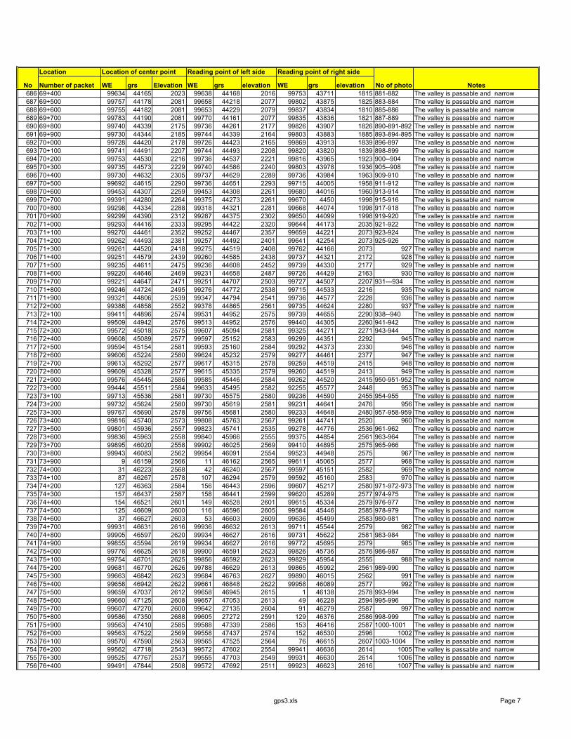
Location Location of center point Reading point of left side Reading point of right side
Number of packet WE grs Elevation WE grs elevation WE grs elevationNo No of photo Notes686 69+400 99634 44165 2023 99638 44168 2016 99753 43711 1815 881-882 The valley is passable and narrow687 69+500 99757 44178 2081 99658 44218 2077 99802 43875 1825 883-884 The valley is passable and narrow688 69+600 99755 44182 2081 99653 44229 2079 99837 43834 1810 885-886 The valley is passable and narrow689 69+700 99783 44190 2081 99770 44161 2077 99835 43836 1821 887-889 The valley is passable and narrow690 69+800 99740 44339 2175 99736 44261 2177 99826 43907 1826 890-891-892 The valley is passable and narrow691 69+900 99730 44344 2185 99744 44339 2164 99803 43883 1885 893-894-895 The valley is passable and narrow692 70+000 99728 44420 2178 99726 44423 2165 99869 43913 1839 896-897 The valley is passable and narrow693 70+100 99741 44491 2207 99744 44493 2208 99820 43820 1839 898-899 The valley is passable and narrow694 70+200 99753 44530 2216 99736 44537 2221 99816 43965 1923 900--904 The valley is passable and narrow695 70+300 99735 44573 2229 99740 44586 2240 99803 43978 1936 905--908 The valley is passable and narrow696 70+400 99730 44632 2305 99737 44629 2289 99736 43984 1963 909-910 The valley is passable and narrow697 70+500 99692 44615 2290 99736 44651 2293 99715 44005 1958 911-912 The valley is passable and narrow698 70+600 99453 44307 2259 99453 44308 2261 99680 44016 1960 913-914 The valley is passable and narrow699 70+700 99391 44280 2264 99375 44273 2261 99670 4450 1998 915-916 The valley is passable and narrow700 70+800 99298 44334 2288 99318 44321 2281 99668 44074 1998 917-918 The valley is passable and narrow701 70+900 99299 44390 2312 99287 44375 2302 99650 44099 1998 919-920 The valley is passable and narrow702 71+000 99293 44416 2333 99295 44422 2320 99644 44173 2035 921-922 The valley is passable and narrow703 71+100 99270 44461 2352 99252 44467 2357 99659 44221 2073 923-924 The valley is passable and narrow704 71+200 99262 44493 2381 99257 44492 2401 99641 42254 2073 925-926 The valley is passable and narrow705 71+300 99261 44520 2418 99275 44519 2408 99762 44166 2073 927 The valley is passable and narrow706 71+400 99251 44579 2439 99260 44585 2438 99737 44321 2172 928 The valley is passable and narrow707 71+500 99235 44611 2475 99236 44608 2452 99739 44330 2177 929 The valley is passable and narrow708 71+600 99220 44646 2469 99231 44658 2487 99726 44429 2163 930 The valley is passable and narrow709 71+700 99221 44647 2471 99251 44707 2503 99727 44507 2207 931---934 The valley is passable and narrow710 71+800 99246 44724 2495 99276 44772 2538 99715 44533 2216 935 The valley is passable and narrow711 71+900 99321 44806 2539 99347 44794 2541 99736 44577 2228 936 The valley is passable and narrow712 72+000 99388 44858 2552 99378 44865 2561 99735 44624 2280 937 The valley is passable and narrow713 72+100 99411 44896 2574 99531 44952 2575 99739 44655 2290 938--940 The valley is passable and narrow714 72+200 99509 44942 2576 99513 44952 2576 99440 44305 2260 941-942 The valley is passable and narrow715 72+300 99572 45018 2575 99607 45094 2581 99325 44271 2271 943-944 The valley is passable and narrow716 72+400 99608 45089 2577 99597 25152 2583 99299 44351 2292 945 The valley is passable and narrow717 72+500 99594 45154 2581 99593 25160 2584 99292 44373 2330 946 The valley is passable and narrow718 72+600 99606 45224 2580 99624 45232 2579 99277 44461 2377 947 The valley is passable and narrow719 72+700 99613 45292 2577 99617 45315 2578 99259 44519 2415 948 The valley is passable and narrow720 72+800 99609 45328 2577 99615 45335 2579 99260 44519 2413 949 The valley is passable and narrow721 72+900 99576 45445 2586 99585 45446 2584 99262 44520 2415 950-951-952 The valley is passable and narrow722 73+000 99444 45511 2584 99633 45495 2582 92255 45577 2448 953 The valley is passable and narrow723 73+100 99713 45536 2581 99730 45575 2580 99236 44590 2455 954-955 The valley is passable and narrow724 73+200 99732 45624 2580 99730 45619 2581 99231 44641 2476 956 The valley is passable and narrow725 73+300 99767 45690 2578 99756 45681 2580 99233 44648 2480 957-958-959 The valley is passable and narrow726 73+400 99816 45740 2573 99808 45763 2567 99261 44741 2520 960 The valley is passable and narrow727 73+500 99801 45936 2557 99823 45741 2535 99278 44776 2536 961-962 The valley is passable and narrow728 73+600 99836 45963 2558 99840 45966 2555 99375 44854 2561 963-964 The valley is passable and narrow729 73+700 99895 46020 2558 99902 46025 2569 99410 44895 2575 965-966 The valley is passable and narrow730 73+800 99943 46083 2562 99954 46091 2554 99523 44948 2575 967 The valley is passable and narrow731 73+900 9 46159 2566 11 46162 2565 99611 45065 2577 968 The valley is passable and narrow732 74+000 31 46223 2568 42 46240 2567 99597 45151 2582 969 The valley is passable and narrow733 74+100 87 46267 2578 107 46294 2579 99592 45160 2583 970 The valley is passable and narrow734 74+200 127 46363 2584 156 46443 2596 99607 45217 2580 971-972-973 The valley is passable and narrow735 74+300 157 46437 2587 158 46441 2599 99620 45289 2577 974-975 The valley is passable and narrow736 74+400 154 46521 2601 149 46528 2601 99615 45334 2579 976-977 The valley is passable and narrow737 74+500 125 46609 2600 116 46596 2605 99584 45446 2585 978-979 The valley is passable and narrow738 74+600 37 46627 2603 53 46603 2609 99636 45499 2583 980-981 The valley is passable and narrow739 74+700 99931 46631 2616 99936 46632 2613 99711 45544 2579 982 The valley is passable and narrow740 74+800 99905 46597 2620 99934 46627 2616 99731 45622 2581 983-984 The valley is passable and narrow741 74+900 99855 45594 2619 99934 46627 2616 99772 45695 2579 985 The valley is passable and narrow742 75+000 99776 46625 2618 99900 46591 2623 99826 45736 2576 986-987 The valley is passable and narrow743 75+100 99754 46701 2625 99856 46592 2623 99829 45954 2555 988 The valley is passable and narrow744 75+200 99681 46770 2626 99788 46629 2613 99865 45992 2561 989-990 The valley is passable and narrow745 75+300 99663 46842 2623 99684 46763 2627 99890 46015 2562 991 The valley is passable and narrow746 75+400 99658 46942 2622 99661 46848 2622 99958 46089 2577 992 The valley is passable and narrow747 75+500 99659 47037 2612 99658 46945 2615 1 46138 2578 993-994 The valley is passable and narrow748 75+600 99660 47125 2608 99657 47053 2613 49 46228 2594 995-996 The valley is passable and narrow749 75+700 99607 47270 2600 99642 27135 2604 91 46279 2587 997 The valley is passable and narrow750 75+800 99586 47350 2688 99605 27272 2591 129 46376 2586 998-999 The valley is passable and narrow751 75+900 99563 47410 2585 99588 47339 2586 153 46416 2587 1000-1001 The valley is passable and narrow752 76+000 99563 47522 2569 99558 47437 2574 152 46530 2596 1002 The valley is passable and narrow753 76+100 99570 47590 2563 99565 47525 2564 76 46615 2607 1003-1004 The valley is passable and narrow754 76+200 99562 47718 2543 99572 47602 2554 99941 46636 2614 1005 The valley is passable and narrow755 76+300 99525 47767 2537 99555 47703 2549 99931 46630 2614 1006 The valley is passable and narrow756 76+400 99491 47844 2508 99572 47692 2511 99923 46623 2616 1007 The valley is passable and narrow
gps3.xls Page 7

Location Location of center point Reading point of left side Reading point of right side
Number of packet WE grs Elevation WE grs elevation WE grs elevationNo No of photo Notes757 76+500 99455 47918 2500 99499 47853 2507 99930 46626 2616 1008 The valley is passable and narrow758 76+600 99410 47989 2482 99543 47926 2492 99880 46586 2620 1009 The valley is passable and narrow759 76+700 99338 48043 2469 99402 47985 2475 99688 46764 2628 1010 The valley is passable and narrow760 76+800 99278 48107 2452 99337 48044 2453 99688 46764 2628 1011-1012 The valley is passable and narrow761 76+900 99229 48196 2456 99279 48108 2451 99659 46863 2622 1013 The valley is passable and narrow762 77+000 99199 48234 2452 99228 48193 2448 99659 47033 2611 1013 The valley is passable and narrow763 77+100 99154 48347 2453 99185 48272 2455 99599 47305 2593 1014 The valley is passable and narrow764 77+200 99118 48426 2449 99155 48355 2454 99599 47309 2593 1015 The valley is passable and narrow765 77+300 99081 48495 2446 99114 48433 2450 99596 47319 2591 1016 The valley is passable and narrow766 77+400 99019 48572 2452 99070 48420 2443 99594 47324 2591 1017 The valley is passable and narrow767 77+500 99018 48615 2470 99022 48555 2456 99559 47462 2568 1018 The valley is passable and narrow768 77+600 99945 48685 2472 98997 48634 2468 99559 47468 2566 1019-1020 The valley is passable and narrow769 77+700 98905 48756 2474 98971 48697 2467 99571 47574 2556 1021 The valley is passable and narrow770 77+800 98882 48850 2474 98903 48764 2476 99570 47587 2554 1022 The valley is passable and narrow771 77+900 98857 48939 2474 98882 48855 2476 99225 47770 2523 1023 The valley is passable and narrow772 78+000 98816 49016 2475 98852 489954 2474 99466 47902 2492 1024 The valley is passable and narrow773 78+100 98818 49016 2474 98813 49016 2476 99465 47904 2492 1025 The valley is passable and narrow774 78+200 98769 49043 2473 98813 49018 2477 99402 47986 2476 1026-1027 The valley is passable and narrow775 78+300 98688 49157 2473 988776 49088 2475 99280 48106 2452 The valley is passable and narrow776 78+400 98636 49232 2479 98726 49156 2473 99280 48106 2452 1028 The valley is passable and narrow777 78+500 98601 49263 2486 98635 49212 2473 99221 48206 2447 1029 The valley is passable and narrow778 78+600 98546 24297 2487 98596 49253 2484 99187 48270 2451 1030 The valley is passable and narrow779 78+700 98470 49335 2486 98517 49326 2487 99156 43353 2451 1031--1033 The valley is passable and narrow780 78+800 98416 49226 2488 98457 49358 2482 99107 48458 2445 1034 The valley is passable and narrow781 78+900 98307 49456 2480 98406 49414 2485 99031 48563 2453 1035 The valley is passable and narrow782 79+000 98252 49511 2481 98307 49457 2479 98810 49023 2474 1036 The valley is passable and narrow783 79+100 98170 49558 2477 98229 49508 2477 98810 49024 2473 1037 The valley is passable and narrow784 79+200 98071 49592 2467 98100 49581 2472 98810 49024 2473 1038 The valley is passable and narrow785 79+300 98008 49645 2470 98073 49591 2474 98810 46025 2473 1039 The valley is passable and narrow786 79+400 97944 49703 2469 98011 49641 2473 98810 49026 2473 1040 The valley is passable and narrow787 79+500 97896 49754 2471 97941 49708 2474 98809 49027 2473 1041 The valley is passable and narrow788 79+600 97836 49826 2478 97885 49769 2472 98809 49027 2473 1042 The valley is passable and narrow789 79+700 97788 49875 2401 97744 49782 2474 98809 49028 2473 1043 The valley is passable and narrow790 79+800 97727 49929 2498 97782 49869 2490 48808 49028 2473 1044 The valley is passable and narrow791 79+900 97663 49821 2505 97740 49891 2492 98808 49029 2473 1045 The valley is passable and narrow792 80+000 97613 49821 2503 97664 49831 2505 98711 49152 2473 1046-1047 The valley is passable and narrow793 80+100 97561 49928 2513 97605 49831 2503 98624 49238 2475 1048 The valley is passable and narrow794 80+200 97471 49927 2532 97469 49926 2530 98536 49304 2478 1049 The valley is passable and narrow795 80+300 97382 49911 2528 97450 49928 2527 98359 49435 2486 1050-1052 The valley is passable and narrow796 80+400 97310 49926 2526 97377 49924 2526 98333 49444 2482 1053 The valley is passable and narrow797 80+500 97252 49856 2523 97295 49922 2521 98331 49445 2482 1054-1055 The valley is passable and narrow798 80+600 97170 49917 2526 97243 49862 2519 98316 49450 2480 1056-1057 The valley is passable and narrow799 80+700 97111 49946 2522 97152 49927 2520 98252 49491 2477 1058 The valley is passable and narrow800 80+800 97011 49996 2499 97108 49961 2518 98134 49568 2474 1059-1060 The valley is passable and narrow801 80+900 96974 50046 2489 97015 49995 2517 97944 49701 2475 1061 The valley is passable and narrow802 81+000 96950 50112 2483 96979 50051 2491 97852 49798 2480 1062 The valley is passable and narrow803 81+100 96937 50180 2474 96947 50110 2491 97835 49812 2481 1063-1064 The valley is passable and narrow804 81+200 96933 50264 2462 96925 50192 2487 97835 49811 2481 104 The valley is passable and narrow805 81+300 96910 50339 2451 96933 50267 2469 97835 49812 2481 1065 The valley is passable and narrow806 81+400 96897 50422 2429 96890 50361 2473 97794 49857 2489 1066 The valley is passable and narrow807 81+500 96873 50498 2438 96895 50424 2439 97723 49908 2500 1067 The valley is passable and narrow808 81+600 96857 50568 2449 96854 50497 2436 97668 49835 2502 1068 The valley is passable and narrow809 81+700 96851 50640 2464 96865 50590 2440 97591 49871 2515 1069 The valley is passable and narrow810 81+800 96873 50714 2469 96852 50647 2444 97421 49925 2525 1070 The valley is passable and narrow811 81+900 96901 50806 2469 96870 50699 2451 97419 49924 2526 1071- 1073 The valley is passable and narrow812 82+000 96900 50850 2471 96904 50801 2485 97416 49923 2526 1074-1075 The valley is passable and narrow813 82+100 96891 50967 2490 96909 50886 2483 96947 50105 2492 1076 The valley is passable and narrow814 82+200 96922 51040 2493 96899 50951 2485 96945 50118 2490 1077-1078 The valley is passable and narrow815 82+300 97010 51419 2421 96913 51039 2488 96905 50349 2452 1079-1080 The valley is passable and narrow816 82+400 97007 51413 2421 97012 51428 2418 96905 50351 2451 1081 The valley is passable and narrow817 82+500 97008 51428 2418 97009 51430 2419 96905 50352 2450 1082 The valley is passable and narrow818 82+600 97016 51470 2417 97011 51433 2418 96904 50353 2450 1083 The valley is passable and narrow819 82+700 97032 51519 2410 97030 51492 2399 96904 50353 2450 1084 The valley is passable and narrow820 82+800 97020 51587 2401 97033 51532 2394 96904 50353 2450 1085 The valley is passable and narrow821 82+900 97039 51624 2398 97031 51572 2394 96903 50354 2450 1086 The valley is passable and narrow822 83+000 97098 51699 2395 97050 51620 2390 96903 50358 2449 1087 The valley is passable and narrow823 83+100 97142 51764 2386 97104 51698 2389 96848 50618 2459 1088 The valley is passable and narrow824 83+200 97217 51829 2384 97134 51763 2429 96851 50637 2463 1089 The valley is passable and narrow825 83+300 97310 51841 2383 97217 51827 2385 96852 50641 2463 1090 The valley is passable and narrow826 83+400 97386 51907 2370 97328 51842 2383 96852 50645 2464 1091-1092 The valley is passable and narrow827 83+500 97361 51922 2350 97365 51892 2369 96907 50866 2484 1093 The valley is passable and narrow
gps3.xls Page 8

Location Location of center point Reading point of left side Reading point of right side
Number of packet WE grs Elevation WE grs elevation WE grs elevationNo No of photo Notes828 83+600 97340 51938 2326 97327 51919 2368 96907 50868 2485 1094 The valley is passable and narrow829 83+700 97327 51991 2264 97323 51945 2318 96891 50171 2495 1095-1096 The valley is passable and narrow830 83+800 97327 51991 2264 97292 51944 2367 96908 51112 2468 1097 The valley is passable and narrow831 83+900 97247 51937 2302 97232 51929 2363 96885 51129 2459 1098 The valley is passable and narrow832 84+000 97241 51975 2321 97233 51934 2364 97014 51429 2417 1099-1100 The valley is passable and narrow833 84+100 97213 51981 2308 97223 51989 2323 97014 51429 2418 1101-1102 The valley is passable and narrow834 84+200 97140 52016 2240 97181 52004 2308 97014 51429 2416 1103-1104 The valley is passable and narrow835 84+300 97115 52052 2237 97138 52025 2246 97023 51481 2418 1105-1106 The valley is passable and narrow836 84+400 97003 52030 2218 97063 52007 2239 97034 51531 2404 1107-1108 The valley is passable and narrow837 84+500 96918 52007 2210 97063 52008 2239 97034 51590 2395 1109 The valley is passable and narrow838 84+600 96872 51944 2209 96989 51999 2221 97093 51676 2389 1110-1111 The valley is passable and narrow839 84+700 96793 51932 2180 96914 51984 2196 97106 51695 2388 1112 The valley is passable and narrow840 84+800 96823 51938 2130 96682 51936 2210 97146 51756 2389 1113-1114 The valley is passable and narrow841 84+900 96644 51908 2161 96813 51935 2188 97234 51822 2335 1115 The valley is passable and narrow842 85+000 96592 51874 2160 96693 51976 2161 97315 51845 2351 1116-1117 The valley is passable and narrow843 85+100 96551 51927 2160 96639 51903 2147 97333 51908 2351 1118-1119 The valley is passable and narrow844 85+200 96480 51936 2160 96604 51856 2138 97320 51935 2326 1120-1121 The valley is passable and narrow845 85+300 96421 51993 2160 96553 51905 2138 97329 51937 2320 1122-1123 The valley is passable and narrow846 85+400 96420 52083 2159 96437 51942 2118 97351 51951 2282 1124-1125 The valley is passable and narrow847 85+500 96393 52127 2048 96431 51956 2110 97351 51951 2282 1126 The valley is passable and narrow848 85+600 96390 52173 2023 96425 52035 2069 97351 51951 2282 1127-1128 The valley is passable and narrow849 85+700 96388 52244 2114 96391 52143 2044 97230 51970 2320 1129-1130 The valley is passable and narrow850 85+800 96363 52336 2005 96389 52176 2027 97201 51986 2448 1131-1132 The valley is passable and narrow851 85+900 96365 52409 2002 96390 52269 2015 97171 5214 2239 1133-1134 The valley is passable and narrow852 86+000 96379 52495 1965 96367 52352 1998 97054 52000 2222 1135-1136 The valley is passable and narrow853 86+100 96350 52576 1959 96370 52416 1980 96887 51962 2221 1137-1138 The valley is passable and narrow854 86+200 96312 52654 1947 96370 52416 1959 96889 51964 2219 1139-1140 The valley is passable and narrow855 86+300 96298 52706 1918 96349 52574 1955 96777 51964 2180 1141- The valley is passable and narrow856 86+400 96245 52789 1883 96324 52643 1937 96775 51963 2175 1142 The valley is passable and narrow857 86+500 96204 52849 1883 96301 52708 1918 96627 51851 2141 1143 The valley is passable and narrow858 86+600 96182 52919 1874 96242 52787 1890 96628 51855 2125 1144 The valley is passable and narrow859 86+700 96134 52980 1865 96206 52851 1880 96593 51867 2135 1145 The valley is passable and narrow860 86+800 96052 53036 1829 96177 52929 1874 96552 51914 2156 1146 The valley is passable and narrow861 86+900 96025 53110 1809 96120 52990 1853 96468 51943 2157 1147 The valley is passable and narrow862 87+000 95988 53209 1797 96049 53021 1831 96426 52014 2063 1148-1149 The valley is passable and narrow863 87+100 95930 53194 1788 96019 53107 1817 96404 52104 2054 1150 The valley is passable and narrow864 87+200 95909 53263 1797 95948 53200 1777 96391 52187 2030 1151-1152 The valley is passable and narrow865 87+300 95898 5337 1845 95930 53210 1773 96373 52497 1950 1153-1154 The valley is passable and narrow866 87+400 95905 53452 1745 95212 53272 1774 96357 52515 1953 1155 The valley is passable and narrow867 87+500 95884 53504 1746 95881 53355 1775 96349 52532 1949 1156-1157 The valley is passable and narrow868 87+600 95843 53574 1764 95838 53583 1759 96351 52539 1949 1158 The valley is passable and narrow869 87+700 95796 53663 174.9 95838 53583 1758 96352 52545 1948 1159 The valley is passable and narrow870 87+800 95754 53740 1756 95800 53654 1755 96353 52583 1943 1160 The valley is passable and narrow871 87+900 95698 53808 1729 95754 53733 1743 96314 52652 1931 1161-1163 The valley is passable and narrow872 88+000 95652 53887 1769 95713 53801 1730 96301 52704 1916 1164 The valley is passable and narrow873 88+100 95563 53928 1696 95713 53801 1730 96253 52802 1901 1165 The valley is passable and narrow874 88+200 95431 53989 1735 95559 53936 1704 96189 52845 1919 1166-1167 The valley is passable and narrow875 88+300 95472 54019 1714 95520 53985 1691 96188 52900 1864 1168 The valley is passable and narrow876 88+400 95448 54059 1752 95450 54003 1668 96112 53006 1856 1169 The valley is passable and narrow877 88+500 95235 54158 1790 95449 54001 1668 96109 53000 1844 1170 The valley is passable and narrow878 88+600 95333 54240 1865 95403 54032 1657 95949 53100 1825 1171 The valley is passable and narrow879 88+700 95267 54322 1620 95323 54138 1679 95949 53105 1825 1172 The valley is passable and narrow880 88+800 95220 54385 1624 95311 54181 1666 95915 53247 1813 1173-1174 The valley is passable and narrow881 88+900 95196 54450 1659 95296 54247 1621 95914 53296 1815 1175-1176 The valley is passable and narrow882 89+000 95183 54534 1607 95293 54261 1580 95863 53537 1753 1177-1178 The valley is passable and narrow883 89+100 95159 54613 1591 95183 54523 1598 95862 53539 1754 1179 The valley is passable and narrow884 89+200 95103 54686 1575 95175 54537 1625 95821 53622 1756 1180-1181 The valley is passable and narrow885 89+300 95051 54748 1613 95096 54686 1591 95812 53633 1757 1182 The valley is passable and narrow886 89+400 94972 54767 1592 95066 54747 1584 95778 53698 1752 1183-1184 The valley is passable and narrow887 89+500 94972 54862 1570 94977 54755 1580 95749 53761 1740 1185 The valley is passable and narrow888 89+600 94947 54935 1601 94980 54814 1578 95703 53826 1730 1186 The valley is passable and narrow889 89+700 94892 54929 1600 94953 54892 1575 95607 53884 1712 1187 The valley is passable and narrow890 89+800 94805 55046 1629 94864 54952 1561 95549 53948 1704 1188 The valley is passable and narrow891 89+900 94811 55120 1551 94863 54951 1566 95479 54006 1701 1189 The valley is passable and narrow892 90+000 94755 55160 1542 94813 55115 1560 95445 53995 1701 1190 The valley is passable and narrow893 90+100 94220 55236 1571 94813 55115 1559 95440 53997 1701 1191 The valley is passable and narrow894 90+200 94719 55236 1569 94749 55161 1543 95335 54152 1666 1192 The valley is passable and narrow895 90+300 94564 55254 1531 94713 55239 1545 95316 54191 1725 1193 The valley is passable and narrow896 90+400 94516 55354 1565 94656 55273 1546 95221 54277 1728 1194 The valley is passable and narrow897 90+500 94517 55408 1529 94511 55333 1532 95225 54419 1604 1195 The valley is passable and narrow898 90+600 94480 55520 1553 94519 55429 1524 95185 54459 1604 1196-1198 The valley is passable and narrow
gps3.xls Page 9

Location Location of center point Reading point of left side Reading point of right side
Number of packet WE grs Elevation WE grs elevation WE grs elevationNo No of photo Notes899 90+700 94429 15570 1516 94518 55430 1524 95177 54536 1604 1199 The valley is passable and narrow900 90+800 94367 55629 1507 94479 55481 1517 95146 54633 1587 1199 The valley is passable and narrow901 90+900 94319 55715 1505 894419 55581 1512 95997 54742 1578 1200 The valley is passable and narrow902 91+000 94231 55730 1498 93365 55637 1492 94992 54742 1579 1201 The valley is passable and narrow903 91+100 94127 55803 1524 94314 55718 1501 94987 54748 1579 1202 The valley is passable and narrow904 91+200 94024 55900 1479 94226 55743 1500 94969 54864 1575 1203 The valley is passable and narrow905 91+300 93988 55943 1476 94065 55835 1480 94933 54947 1574 1204 The valley is passable and narrow906 91+400 93972 56028 1470 94063 55837 1479 94862 54954 1561 1205 The valley is passable and narrow907 91+500 93928 56107 1461 94000 55929 1479 94839 55037 1564 1206 The valley is passable and narrow908 91+600 93930 56176 1452 93984 56029 1467 94821 55113 1547 1207 The valley is passable and narrow909 91+700 93846 56237 1444 93936 56092 1465 94712 55243 1559 1208 The valley is passable and narrow910 91+800 93824 56308 1445 93941 56177 1459 94660 55276 1545 1209 The valley is passable and narrow911 91+900 93758 56374 1467 93848 56239 1451 94575 55243 1538 1210 The valley is passable and narrow912 92+000 93747 56487 1501 93829 56319 1446 94512 55446 1519 1211 The valley is passable and narrow913 92+100 93604 56502 1512 93783 56396 1444 94508 55454 1519 1212 The valley is passable and narrow914 92+200 93650 56611 1420 93711 56473 1438 94506 55455 1519 1213-1214 The valley is passable and narrow915 92+300 93616 56778 1407 93651 56553 1422 94453 55505 1519 1215 The valley is passable and narrow916 92+400 93593 56800 1406 93646 56629 1424 94419 55567 1518 1216-1217 The valley is passable and narrow917 92+500 93545 56863 1410 93630 56714 1417 94349 55648 1513 1218-1219 The valley is passable and narrow918 92+600 93482 56955 1404 93585 56789 1412 94316 55716 1507 1220 The valley is passable and narrow919 92+700 93439 56995 1412 93552 56854 1407 94225 55732 1505 1221 The valley is passable and narrow920 92+800 93316 57120 1387 93511 56933 1406 94015 55756 1499 1222 The valley is passable and narrow921 92+900 93210 57133 1393 93435 56991 1408 94068 55836 1478 1223 The valley is passable and narrow922 93+000 93200 57128 1392 93373 57031 1401 94008 55925 1475 1224 The valley is passable and narrow923 93+100 93094 57205 1372 93315 57129 1391 93981 56016 1470 1225-1226 The valley is passable and narrow924 93+200 93087 57208 1372 93261 57225 1391 93976 56023 1470 1227 The valley is passable and narrow925 93+300 93024 57257 1376 93148 57143 1384 93934 56179 1462 1228 The valley is passable and narrow926 93+400 92978 57268 1378 93033 57262 1377 93870 56237 1456 1229 The valley is passable and narrow927 93+500 92948 57343 1377 92966 57258 1377 93831 56314 1446 1230 The valley is passable and narrow928 93+600 92847 57362 1376 92936 57346 1378 93790 56388 1444 1231 The valley is passable and narrow929 93+700 92768 57367 1372 92947 57348 1382 93713 56472 1450 1232 The valley is passable and narrow930 93+800 92671 57431 1383 92857 57364 1382 93709 56480 1447 1233 The valley is passable and narrow931 93+900 92440 57472 1361 92687 57413 1366 93656 56547 1436 1234 The valley is passable and narrow932 94+000 92529 57468 1354 92684 57414 1367 93649 56624 1424 1235 The valley is passable and narrow933 94+100 92378 57468 1368 92645 57448 1365 93588 56796 1416 1236--1238 The valley is passable and narrow934 94+200 92354 57477 1345 92534 57477 1330 93545 56868 1412 1239 The valley is passable and narrow935 94+300 92273 57485 1345 92520 57493 1348 93524 56942 1411 1240 The valley is passable and narrow936 94+400 92157 57508 1355 92345 57478 1349 93443 56986 1402 1241 The valley is passable and narrow937 94+500 92060 57514 1328 92252 57492 1348 93387 57048 1401 1242 The valley is passable and narrow938 94+600 91984 57525 1331 92151 57508 1340 93321 57114 1396 1243 The valley is passable and narrow939 94+700 91880 57536 1333 92099 57506 1335 93321 57114 1396 1244 The valley is passable and narrow940 94+800 91813 57546 1314 91994 57526 1326 93229 57141 1394 1245 The valley is passable and narrow941 94+900 91707 57534 1312 91902 57534 1322 93147 57125 1390 1246 The valley is passable and narrow942 95+000 91630 57567 1308 91802 57542 1313 93099 57191 1381 1247 The valley is passable and narrow943 95+100 91579 57612 1306 91713 57531 1313 92965 57272 1380 1248 The valley is passable and narrow944 95+200 91486 57657 1306 91631 57561 1310 92938 57343 1379 1249 The valley is passable and narrow945 95+300 91390 57676 1302 91557 57624 1303 92943 57344 1330 1250 The valley is passable and narrow946 95+400 91302 57595 1288 91478 57667 1301 92843 57362 1377 1251 The valley is passable and narrow947 95+500 91267 57536 1285 91381 57669 1294 92761 57378 1369 1252-1253 The valley is passable and narrow948 95+600 91193 57493 1289 91263 57532 1287 92683 57416 1369 1254 The valley is passable and narrow949 95+700 91054 57519 1282 91102 57495 1282 92613 57471 1364 1255 The valley is passable and narrow950 95+800 91014 57537 1281 91004 57535 1277 92534 57470 1351 1256 The valley is passable and narrow951 95+900 90903 57560 1278 91004 57536 1277 92403 57465 1352 1256 The valley is passable and narrow952 96+000 90859 57582 1270 90935 57753 1272 92343 57479 1348 1257-1258 The valley is passable and narrow953 96+100 90775 57613 1263 90934 57536 1272 92253 57494 1332 1259 The valley is passable and narrow954 96+200 90684 57638 1262 90845 57593 1273 92168 57507 1340 1260 The valley is passable and narrow955 96+300 90559 57693 1254 90749 57622 1268 92085 57503 1329 1261 The valley is passable and narrow956 96+400 90497 57769 1291 90660 57633 1267 91992 57527 1325 1262 The valley is passable and narrow957 96+500 90415 57826 1249 90570 57702 1257 91890 57527 1328 1263 The valley is passable and narrow958 96+600 90269 57880 1240 90506 57762 1254 91804 57544 1313 1264 The valley is passable and narrow959 96+700 90242 57884 1241 90414 57823 1250 91724 57552 1315 1265 The valley is passable and narrow960 96+800 90145 57914 1278 90316 57867 1245 91646 57557 1311 1266 The valley is passable and narrow961 96+900 89982 57916 1315 90229 57891 1242 91561 57612 1309 1267 The valley is passable and narrow962 97+000 89881 57910 1239 90024 57924 1237 91507 57648 1304 1268 The valley is passable and narrow963 97+100 89817 57921 1234 89937 57907 1231 91397 57666 1302 1269 The valley is passable and narrow964 97+200 89745 57941 1224 89743 57953 1226 91260 57521 1293 1270 The valley is passable and narrow965 97+300 89687 57971 1222 89741 57953 1226 91098 57497 1287 1271-1272 The valley is passable and narrow966 97+400 89504 57988 1220 89740 57954 1226 91006 57533 1277 1273 The valley is passable and narrow967 97+500 89430 58023 1215 89625 57974 1223 90975 57543 1278 1274 The valley is passable and narrow968 97+600 89324 58057 1210 89527 57987 1217 90971 57544 1279 1275 The valley is passable and narrow969 97+700 89236 58087 1206 89428 58022 1216 90915 57560 1282 1276 The valley is passable and narrow
gps3.xls Page 10

Location Location of center point Reading point of left side Reading point of right side
Number of packet WE grs Elevation WE grs elevation WE grs elevationNo No of photo Notes970 97+800 89087 58116 1196 89311 58063 1216 90842 57589 1271 1277 The valley is passable and narrow971 97+900 88975 58138 1200 89228 58097 1206 90747 57620 1275 1278 The valley is passable and narrow972 98+000 88893 58161 1194 89115 58116 1199 90659 57635 1262 1279 The valley is passable and narrow973 98+100 88807 58168 1183 89984 58148 1195 90562 57689 1257 1280 The valley is passable and narrow974 98+200 88703 58188 1184 88882 58168 1192 90506 57755 1254 1281 The valley is passable and narrow975 98+300 88600 58191 1177 88810 58172 1188 90416 57823 1249 1282-1283 The valley is passable and narrow976 98+400 88497 58149 1173 88681 58175 1177 90316 57864 1244 1284 The valley is passable and narrow977 98+500 88447 58110 1209 88587 58180 1175 90231 57892 1242 1285-1286 The valley is passable and narrow978 98+600 88311 58056 1165 88497 58150 1174 90146 57923 1242 1287 The valley is passable and narrow979 98+700 88253 58028 1163 88452 58126 1162 90037 57924 1222 1288 The valley is passable and narrow980 98+800 88172 57982 1159 88304 58052 1165 89935 57907 1236 1289-1290 The valley is passable and narrow981 98+900 88002 57925 1154 88230 57990 1163 89826 57916 1232 1291 The valley is passable and narrow982 99+000 87940 57900 1155 88140 57968 1157 89737 57949 1228 1292 The valley is passable and narrow983 99+100 87786 57813 1155 88007 57919 1142 89616 57974 1224 1293 The valley is passable and narrow984 99+200 87600 57753 1138 87881 57859 1150 89539 57977 1227 1294 The valley is passable and narrow985 99+300 87600 57754 1139 87790 57812 1149 89423 58028 1217 1295 The valley is passable and narrow986 99+400 87511 57661 1136 87693 57769 1147 89323 58046 1223 1296 The valley is passable and narrow987 99+500 87212 57757 1124 87586 57754 1135 89220 58084 1202 1297 The valley is passable and narrow988 99+600 87043 57722 1116 87488 57754 1124 89109 58112 1200 1298 The valley is passable and narrow989 99+700 87030 57726 1115 87364 57775 1134 88890 58159 1199 1299 The valley is passable and narrow990 99+800 86946 57729 1112 87263 57763 1127 88892 58159 1194 1300 The valley is passable and narrow991 99+900 86817 57734 1115 87158 57746 1122 88802 58172 1183 1301- The valley is passable and narrow992 100+000 86750 57739 1103 87048 57722 1116 88681 58180 1182 1302 The valley is passable and narrow993 100+100 86637 57764 1101 86967 57736 1115 88592 58190 1179 1303--1305 The valley is passable and narrow994 100+200 86519 57764 1100 86822 57734 1111 88500 58153 1174 1306 The valley is passable and narrow995 100+300 86456 57802 1093 86761 57740 1108 88417 58108 1173 1307 The valley is passable and narrow996 100+400 86229 57757 1087 86611 57770 1104 88306 58054 1162 1308-1309 The valley is passable and narrow997 100+500 86228 57769 1089 86545 57763 1105 88231 58001 1160 1310 The valley is passable and narrow998 100+600 86126 57790 1083 86435 57813 1100 88113 57956 1157 1311 The valley is passable and narrow999 100+700 86033 57799 1081 86330 57774 1091 88042 57923 1152 1312 The valley is passable and narrow
1000 100+800 85873 57816 1073 86225 57777 1077 87896 57885 1190 1313 The valley is passable and narrow1001 100+900 85781 57796 1067 86081 57788 1077 87804 57818 1142 1314 The valley is passable and narrow1002 101+000 85694 57809 1072 86020 57793 1075 87693 57777 1139 1315 The valley is passable and narrow1003 101+100 85640 57815 1071 85817 57806 1073 87490 57760 1131 1316 The valley is passable and narrow1004 101+200 85564 57847 1067 85774 57797 1072 87489 57761 1135 1317 The valley is passable and narrow1005 101+300 85465 57901 1067 85683 57811 1071 87342 57736 1172 1318-1319 The valley is passable and narrow1006 101+400 85383 57902 1061 85659 57794 1043 87263 57754 1123 1320 The valley is passable and narrow1007 101+500 85299 57906 1059 85494 57876 1058 87161 57748 1127 1321 The valley is passable and narrow1008 101+600 85201 57881 1056 85469 57880 1065 87052 57721 1118 1322 The valley is passable and narrow1009 101+700 85098 57890 1051 85372 57896 1062 86946 57729 1117 1323 The valley is passable and narrow1010 101+800 84975 57865 1045 85281 57886 1059 86843 57728 1112 1324 The valley is passable and narrow1011 101+900 84917 57847 1041 85187 57863 1066 86756 5774 1107 1325 The valley is passable and narrow1012 102+000 84795 57875 1044 85087 57889 1048 86638 57769 1102 1326 The valley is passable and narrow1013 102+100 84679 57893 1037 84987 57873 1047 86544 57759 1095 1327 The valley is passable and narrow1014 102+200 84566 57843 1029 84906 57865 1041 86455 57806 1094 1328 The valley is passable and narrow1015 102+300 84450 57889 1029 84798 57867 1040 86341 57784 1090 1329 The valley is passable and narrow1016 102+400 84441 57989 1028 84640 57844 1027 86222 57775 1087 1330 The valley is passable and narrow1017 102+500 84419 58079 1029 84532 57844 1031 86114 57791 1083 1331 The valley is passable and narrow1018 102+600 84408 58159 1029 84444 57891 1031 86010 57804 1082 1332 The valley is passable and narrow1019 102+700 84386 58285 1034 84442 57969 1030 85872 57816 1075 1333 The valley is passable and narrow1020 102+800 84364 58356 1036 84416 58088 1029 85874 57798 1075 1334 The valley is passable and narrow1021 102+900 84339 58423 1043 84411 58167 1033 85689 57812 1070 1335 The valley is passable and narrow1022 103+000 84302 58516 1045 84392 58243 1032 85644 57819 1071 1336 The valley is passable and narrow1023 103+100 84219 58806 1115 84365 58350 1033 85537 57864 1071 1337 The valley is passable and narrow1024 103+200 84217 58806 1114 84335 58439 1042 85456 57886 1066 1338 The valley is passable and narrow1025 103+300 84218 58805 1112 84297 58524 1024 85362 57900 1062 1339 The valley is passable and narrow1026 103+400 84255 58937 1098 84296 58623 1054 85268 57886 1058 1340 The valley is passable and narrow1027 103+500 84260 59057 1101 84247 58722 1067 85168 57866 1053 1341 The valley is passable and narrow1028 103+600 84270 59135 1099 84211 58804 1068 85088 57892 1052 1342 The valley is passable and narrow1029 103+700 84276 59164 1096 84259 58957 1095 84983 57874 1047 1343 The valley is passable and narrow1030 103+800 84240 59285 1088 84258 59057 1101 84900 57863 1045 1345 The valley is passable and narrow1031 103+900 84208 59359 1081 84267 59142 1097 84802 57874 1043 1346 The valley is passable and narrow1032 104+000 84159 59436 1069 84301 59212 1091 84694 57855 1033 1347-1348 The valley is passable and narrow1033 104+100 84237 59541 1054 84243 59256 1087 84569 57841 1030 1349 The valley is passable and narrow1034 104+200 84080 59228 1052 84217 59361 1056 84431 57889 1029 1350 The valley is steep and narrow1035 104+300 84017 59677 1061 84167 59442 1054 84433 57977 1022 1351 The valley is steep and narrow1036 104+400 83994 59741 1063 84134 59539 1039 84425 58084 1031 1352-1353 The valley is steep and narrow1037 104+500 83938 59879 1061 84090 59620 1038 84410 58176 1034 1354 The valley is steep and narrow1038 104+600 83821 59960 1061 83997 59764 1065 84389 58274 1039 1355 The valley is steep and narrow1039 104+700 83779 59858 1043 83998 59764 1095 84365 58370 1038 1356 The valley is steep and narrow1040 104+800 83698 59847 1034 83955 59855 1064 84338 58447 1041 1357 The valley is steep and narrow
gps3.xls Page 11
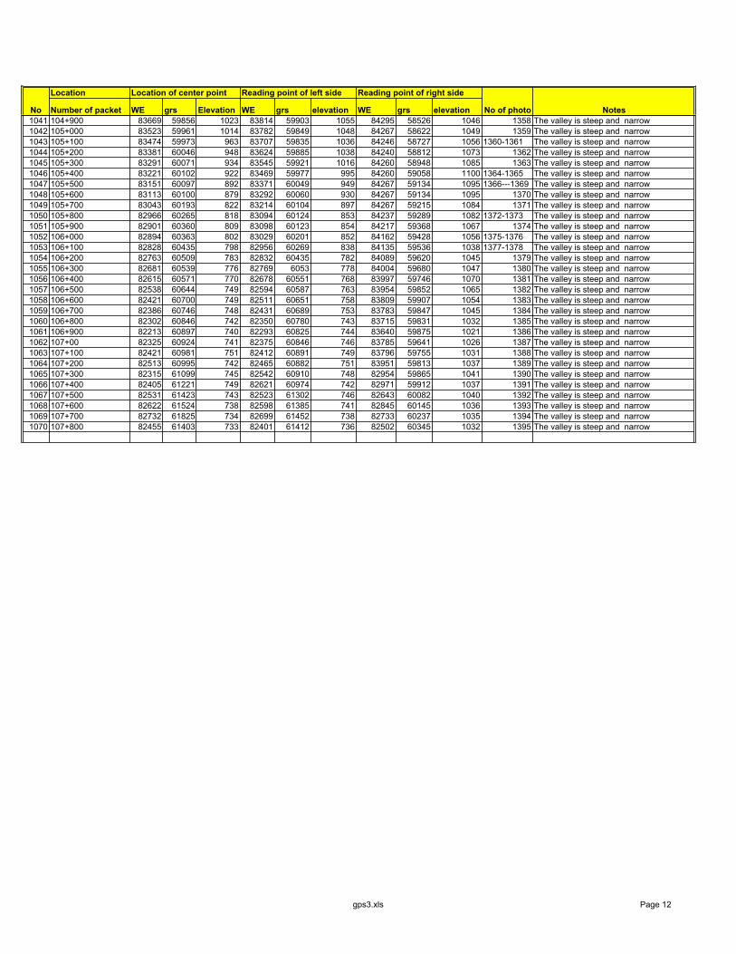
Location Location of center point Reading point of left side Reading point of right side
Number of packet WE grs Elevation WE grs elevation WE grs elevationNo No of photo Notes1041 104+900 83669 59856 1023 83814 59903 1055 84295 58526 1046 1358 The valley is steep and narrow1042 105+000 83523 59961 1014 83782 59849 1048 84267 58622 1049 1359 The valley is steep and narrow1043 105+100 83474 59973 963 83707 59835 1036 84246 58727 1056 1360-1361 The valley is steep and narrow1044 105+200 83381 60046 948 83624 59885 1038 84240 58812 1073 1362 The valley is steep and narrow1045 105+300 83291 60071 934 83545 59921 1016 84260 58948 1085 1363 The valley is steep and narrow1046 105+400 83221 60102 922 83469 59977 995 84260 59058 1100 1364-1365 The valley is steep and narrow1047 105+500 83151 60097 892 83371 60049 949 84267 59134 1095 1366---1369 The valley is steep and narrow1048 105+600 83113 60100 879 83292 60060 930 84267 59134 1095 1370 The valley is steep and narrow1049 105+700 83043 60193 822 83214 60104 897 84267 59215 1084 1371 The valley is steep and narrow1050 105+800 82966 60265 818 83094 60124 853 84237 59289 1082 1372-1373 The valley is steep and narrow1051 105+900 82901 60360 809 83098 60123 854 84217 59368 1067 1374 The valley is steep and narrow1052 106+000 82894 60363 802 83029 60201 852 84162 59428 1056 1375-1376 The valley is steep and narrow1053 106+100 82828 60435 798 82956 60269 838 84135 59536 1038 1377-1378 The valley is steep and narrow1054 106+200 82763 60509 783 82832 60435 782 84089 59620 1045 1379 The valley is steep and narrow1055 106+300 82681 60539 776 82769 6053 778 84004 59680 1047 1380 The valley is steep and narrow1056 106+400 82615 60571 770 82678 60551 768 83997 59746 1070 1381 The valley is steep and narrow1057 106+500 82538 60644 749 82594 60587 763 83954 59852 1065 1382 The valley is steep and narrow1058 106+600 82421 60700 749 82511 60651 758 83809 59907 1054 1383 The valley is steep and narrow1059 106+700 82386 60746 748 82431 60689 753 83783 59847 1045 1384 The valley is steep and narrow1060 106+800 82302 60846 742 82350 60780 743 83715 59831 1032 1385 The valley is steep and narrow1061 106+900 82213 60897 740 82293 60825 744 83640 59875 1021 1386 The valley is steep and narrow1062 107+00 82325 60924 741 82375 60846 746 83785 59641 1026 1387 The valley is steep and narrow1063 107+100 82421 60981 751 82412 60891 749 83796 59755 1031 1388 The valley is steep and narrow1064 107+200 82513 60995 742 82465 60882 751 83951 59813 1037 1389 The valley is steep and narrow1065 107+300 82315 61099 745 82542 60910 748 82954 59865 1041 1390 The valley is steep and narrow1066 107+400 82405 61221 749 82621 60974 742 82971 59912 1037 1391 The valley is steep and narrow1067 107+500 82531 61423 743 82523 61302 746 82643 60082 1040 1392 The valley is steep and narrow1068 107+600 82622 61524 738 82598 61385 741 82845 60145 1036 1393 The valley is steep and narrow1069 107+700 82732 61825 734 82699 61452 738 82733 60237 1035 1394 The valley is steep and narrow1070 107+800 82455 61403 733 82401 61412 736 82502 60345 1032 1395 The valley is steep and narrow
gps3.xls Page 12