Embed Size (px)
Citation preview

Australian Government
Department of Infrastructure and Regional DevelopmentIssued by the
Administrator of Vehicle Standardsin consultation with the
Australian Motor Vehicle Certification Boardcomprising Commonwealth, State and Territory representatives
NATIONAL CODE OF PRACTICE
VEHICLE STANDARDS BULLETIN VSB 5
MANUFACTURE AND INSTALLATIONOF ADDITIONAL SEATS
Issue 3.0 – Revision 1.0
Replaces VSB 5A & VSB 5B dated November 2003
This Code does not cover administrative requirements imposed by State, Territory and Federal jurisdictions
This Code of Practice is intended as a guide for all manufacturers and installers of additional seats used in
motor vehicles
Department of Infrastructure and Regional Development - Vehicle Safety StandardsGPO Box 594 Canberra ACT 2601
Telephone (02) 6274 7111 Fax (02) 6274 7714
PREFACE
This Vehicle Standards Bulletin 5 (VSB 5) was prepared by the Australian Motor Vehicle Certification Board to replace the version issued in November 2003 comprising two parts, VSB 5A Commercial manufacture and installation of additional seats and VSB 5B Construction and installation of additional seats by individuals. This VSB 5 specifies a range of design and performance requirements that apply to replacement or additional seats in motor vehicles in order to provide protection to occupants in the event of a crash.
The major revisions in this edition of VSB 5 include:
a) Combining the requirements of VSB 5A and VSB 5B.
b) Removing side-facing seats.
c) Introducing shoulder marking labels to indicate the range of occupants who can use the seat based on their Shoulder heights.
d) Changing the categorisation of Category 2 and Category 3 seats to revise the lower age ranges of occupants allowed to use the seats.
e) Introducing anti-submarining feature(s) in Category 2 and 3 seats.
f) Removing child safety harnesses due to difficulties in using them correctly and their likelihood of their contributing to Submarining.
g) Introducing the requirement that Category 2 and 3 seats must have seat belts that are integrated into the seat structure.
Department of Infrastructure and Regional Development - Vehicle Safety StandardsGPO Box 594 Canberra ACT 2601
Telephone (02) 6274 7111 Fax (02) 6274 7714

Table of Contents1 SCOPE..................................................................................................................5
1.1 General...........................................................................................................5
1.2 New Vehicles..................................................................................................5
1.3 In-service Vehicles..........................................................................................5
2 APPLICABILITY...................................................................................................53 EVIDENCE OF COMPLIANCE.............................................................................54 DOCUMENTS REFERRED TO IN THIS VSB 5...................................................65 SEAT CATEGORY AND SELECTION.................................................................66 SEAT LOCATION REQUIREMENTS...................................................................7
6.1 General...........................................................................................................7
6.2 Interference with Existing Safety Equipment..................................................7
6.3 Relocation of Spare Wheel.............................................................................8
6.4 Installation Kit.................................................................................................8
7 SEAT CONSTRUCTION.......................................................................................87.1 General...........................................................................................................8
7.2 Seat Dimensions.............................................................................................8
7.3 Space Requirements......................................................................................9
7.3.1 Head Space...........................................................................................10
7.3.2 Leg Space..............................................................................................11
7.4 Anti-Submarining Feature.............................................................................12
7.5 Seat Belt.......................................................................................................12
7.6 Seat belt Anchorages...................................................................................13
7.6.1 Location of seat belt anchorages...........................................................13
7.7 Strength of Seat and Seat Belt Anchorages.................................................14
7.7.1 General..................................................................................................14
7.7.2 Forward-facing Seats.............................................................................14
7.7.3 Rearward-facing Seats...........................................................................17
7.8 Child Restraint Anchorage Points.................................................................17
7.9 Head Restraints............................................................................................18
7.10 Padding.....................................................................................................20
7.10.1 Seat Padding Requirements...............................................................20
7.10.2 Energy Absorbing (Padded) Seat Backs............................................20
8 LABELLING AND MARKING OF SEATS..........................................................218.1 Manufacturer’s Labels and Installer’s Labels................................................21
8.2 Usage Labels for Category 2 and 3 Seats....................................................21
Issue 3.0 Revision 1.0 Page 3 of 24 28 March 2017

8.3 Shoulder Height Marking..............................................................................22
APPENDIX A – DEFINITIONS..................................................................................24
Issue 3.0 Revision 1.0 Page 4 of 24 28 March 2017

1 SCOPE
1.1 General
This Vehicle Standards Bulletin 5 (VSB 5) provides information for manufacturers, suppliers and installers of Additional seats in motor vehicles to assist them in ensuring that seats they manufacture, supply and/or install provide at least the minimum levels of protection to their occupants required by vehicle standards. It applies to the type of vehicles listed in Section 2.
1.2 New Vehicles
If Additional seats are fitted to a New vehicle resulting in it changing from a goods carrying vehicle (NA or NB1 category) to a passenger carrying vehicle (MA, MB or MC category), the modified vehicle must have an approved Second Stage Manufacturers plate affixed.
1.3 In-service Vehicles
Additional seats fitted into In-service vehicles may be constructed and installed in accordance with this VSB 5 as an alternative to meeting the vehicle standards requirements under the applicable state or territory transport legislation.
2 APPLICABILITY
This VSB 5 may be used for the manufacture and installation of Additional seats in the types of motor vehicles listed in Table 1:
Table 1. Vehicle ApplicabilityADR CATEGORY TYPE OF VEHICLEMA Passenger car
MB Forward control passenger vehicle
MC Off-road passenger vehicle
MD Light omnibus
NA Light goods carrying vehicle with a GVM of 3.5t or less
NB1 Medium goods carrying vehicle with GVM over 3.5t up to 4.5t
While VSB 5 has previously provided guidelines for the manufacture and installation of side-facing seats, they are no longer supported by this document due to their inherent safety problems. Manufacture and installation of such a seat must comply with all the applicable ADRs.
3 EVIDENCE OF COMPLIANCE
Seat manufacturers and installers must obtain and retain engineering evidence that a particular seat, seat belt, anchorage and/or installation comply with the requirements of this VSB 5. If a seat is imported from abroad or from another jurisdiction, it is the responsibility of the supplier/distributor to obtain and retain this information.
Issue 3.0 Revision 1.0 Page 5 of 24 28 March 2017

If a registering authority requires evidence to demonstrate that an Additional seat installation complies with the requirements of this VSB 5, the evidence must be submitted in the form of test results and engineering analysis certified by a signatory who is acceptable to the registering authority.
4 DOCUMENTS REFERRED TO IN THIS VSB 5
The following documents are referred to in this VSB 5:
Australian Design Rules (ADR)3/-- Seats and seat anchorages
4/-- Seatbelts
5/-- Seatbelt anchorages
34/-- Child restraint anchorages and child restraint anchor fittings
68/-- Occupant protection in busesNote: Reference to ADR xx/... means the latest rule is being specified of the relevant 3rd Edition
ADR at the date of modification.
The version of the ADR must either the one that applied at the time the vehicles was manufactured or a later version.
Vehicle Standard Bulletins14 National code of practice for light vehicle construction and modification
Australian/New Zealand StandardsAS/NZS 2596 Seat belt assemblies for motor vehicles
5 SEAT CATEGORY AND SELECTION
For the purpose of this VSB 5, Additional seats are divided into three categories to allow seats to be designed and installed for occupants of different ages:
Category 1 - Seats intended for use by adults and which can be used to accommodate a Child restraint.
Category 2 - Seats suitable for children approximately 4 to 12 years of age and which may be used to accommodate a Child restraint depending on the type and size of the Child restraint.
Category 3 - Seats suitable for children approximately 4 to 7 years of age and which cannot be used to accommodate a Child restraint.
Category 1 seats must comply with the version of ADR 3/--, ADR 4/-- and ADR 5/-- that applies to the vehicle. Additionally, they may be required to comply with a version of ADR 34/-- that applies to the vehicle.Note: A vehicle can no longer be classified as a goods carrying vehicle if the combined occupant
mass (based on 68kg per occupant) is equal to, or exceeds, 50% of the vehicle’s payload (the difference between the vehicle’s GVM and its ‘Unladen Mass’).
All Additional seats intended for use in front seating positions must comply with all the applicable ADRs.
Issue 3.0 Revision 1.0 Page 6 of 24 28 March 2017

6 SEAT LOCATION REQUIREMENTS
6.1 General
Careful consideration must be given to the suitability of the vehicle before Additional seat(s) are installed. If the answer to any of the questions listed in Table 2 is ‘No’, the modification should not be carried out.
Table 2. Suitability of vehicleSuitability of vehicle Yes NoIs the space available in the vehicle sufficient to accommodate the Additional seats and occupants? Specifications for the space required for Additional seats and occupants are set out in Figures 3 and 4;
Y N
Is access and egress from all seats sufficient to allow a person to enter and exit the vehicle, operate door latches, folding seat controls without difficulty or hindrance?
Y N
Will access to seats installed in a vehicle's load space remain un-obstructed by any load being carried?
Y N
If an existing seat is modified to improve access, e.g. by installing a folding mechanism, is evidence provided to demonstrate that the modified seat complies with the relevant version of ADR 3/--?
Y N
Are fittings, including seat backs, padded to prevent injury if they intrude into the head space shown in Figure 3?
Y N
Are the Additional seats, head restraints (if fitted), and their occupants located so as to not adversely affect the driver’s rearward visibility? Additional external rear vision mirrors may be required if rearward vision is impaired.
Y N
Additional seats should not be installed in the vehicle where there is a high probability that occupants will be injured in a crash − for example there is a high probability that an occupant in a rear facing seat in the rear of a small station wagon would suffer leg injuries in a rear end collision, because the occupant's legs are located in an area that will crumple as a result of the impact forces.
Additional seats shall not impose any loads on existing seats, unless it is demonstrated that the original seats can carry the additional loads
6.2 Interference with Existing Safety Equipment
The Additional seats, relocated spare wheels and their associated equipment, shall not prevent or restrict the use of existing safety devices such as seat belts and Child restraint anchorages, unless alternatives that comply with all the applicable ADRs are provided.Note: Child restraint anchorages are designed to withstand only those loads imposed by correctly
fitted child restraints.
Issue 3.0 Revision 1.0 Page 7 of 24 28 March 2017

6.3 Relocation of Spare Wheel
If Additional seats are to be installed in the spare wheel well of the vehicle, the spare wheel may need to be relocated. When relocating the spare wheel, its mounting must be of sufficient strength to withstand a deceleration of 20 times the weight of the spare wheel and its mounting in the forward, rearward or sideways direction.
The spare wheel and its mounting must not cause a hazardous projection for the vehicle's occupants.
6.4 Installation Kit
Seats supplied for installation by others shall include an installation kit which contains the following:
• Installation Instructions
Comprehensive and easily understood installation instructions which cover the make and model of vehicle that the seat is intended to fit. The installation instructions must be such that when correctly followed, the seat installation will comply with all the requirements of this VSB 5. The instructions must be in English and supporting diagrams must use SI Units.
• Installation Hardware
Installation hardware such as bolts, nuts, lock washers, spacers and backing plates sufficient to allow the seat, seat belts, and all necessary components to be installed correctly.
• Seat Label
The seat label or plate as required by the Section 8 ‘LABELLING AND MARKING OF SEATS’.
7 SEAT CONSTRUCTION
7.1 General
Seat frames must be constructed so that there are no sharp edges or projections likely to cause injury to occupants.
7.2 Seat Dimensions
The minimum effective cushion width (W) and the maximum cushion depth (D) for each seating position must be at least that shown in Figure 1 and Table 3.
Issue 3.0 Revision 1.0 Page 8 of 24 28 March 2017

Figure 1. Seat Dimensions
Table 3. Seat Dimensions
Dimensions Effective cushion width (W) min Depth (D) maxCategory 1 Seats 410 mm 500 mm
Category 2 Seats 350 mm 320 mm
Category 3 Seats 290 mm 320 mm
The effective cushion width is measured as per the one determined below:
The effective cushion width is the width of the seat cushion measured horizontally at the intersection of the seat cushion with the transverse plane through the Torso Reference Line.
The effective cushion width is determined by an analysis of seat, seat back and vehicle structure sections on the transverse plane:
o if a cushion is separated from another cushion by less than 100 mm the two cushions must be regarded as continuous; and
o if an end of the cushion is separated from adjoining structure by less than 100 mm it must be regarded as extending to the adjoining structure.
7.3 Space Requirements
The head space and leg space requirements specified below shall apply to each seating position and, if the seat is adjustable, must be maintained throughout the range of seat travel or adjustment.
The template shown in Figure 2 should be used to assist in determining compliance with these requirements.
With reference to Figure 3, position the template on the seat’s centreline with the Point D contacting the seat back.
Issue 3.0 Revision 1.0 Page 9 of 24 28 March 2017

Point C on the template represents the Seating Reference Point and is used to locate the centre of the Radius A and of Radius B.
Figure 2. Template for Determining Head and Leg SpaceIf the seatback is adjustable, set it at the manufacturer’s nominated position or if that position is unknown or not nominated, set it at 25°.
Figure 3. Head Space
7.3.1 Head Space
No part of the vehicle body or component of the roof installation may project below the shaded zone shown in Figure 3.
The head space is the area contained within:
a vertical plane at each end of the seat cushion perpendicular to vehicle’s horizontal lateral axis, and
Issue 3.0 Revision 1.0 Page 10 of 24 28 March 2017

a surface formed by an arc of Radius A extending between a line 45 degrees forward of a vertical plane through point C and 25 degrees rearward of a vertical plane through point C. The minimum requirement for Radius A for Category 1, 2 and 3 seats must be at least that shown in Table 4.
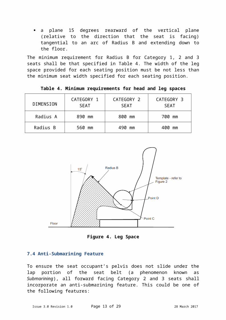
7.3.2 Leg Space
No part of the vehicle body, vehicle equipment or another seat may project into the shaded leg space shown in Figure 4.
The leg space is the area contained within:
a vertical plane at each end of the seat cushion perpendicular to the vehicle’s horizontal lateral axis, and
a plane 45 degrees forward above the horizontal plane through point C; and a plane 15 degrees rearward of the vertical plane (relative to the direction that
the seat is facing) tangential to an arc of Radius B and extending down to the floor.
The minimum requirement for Radius B for Category 1, 2 and 3 seats shall be that specified in Table 4. The width of the leg space provided for each seating position must be not less than the minimum seat width specified for each seating position.
Table 4. Minimum requirements for head and leg spaces
DIMENSIONCATEGORY 1
SEATCATEGORY 2
SEATCATEGORY 3
SEAT
Radius A 890 mm 800 mm 700 mm
Radius B 560 mm 490 mm 400 mm
Figure 4. Leg Space
Issue 3.0 Revision 1.0 Page 11 of 24 28 March 2017

7.4 Anti-Submarining Feature
To ensure the seat occupant’s pelvis does not slide under the lap portion of the seat belt (a phenomenon known as Submarining), all forward facing Category 2 and 3 seats shall incorporate an anti-submarining feature. This could be one of the following features:
An anti-submarining cushion/pan where the front edge of seat cushion has a separate bolster made from significantly higher or stiffer material than the rear of the seat cushion, or a contoured pan that provides the support necessary for the seat’s front bolster to be effective.
Or any other features that can prevent the lap belt to ride up into the abdomen area of the occupant in the event of a crash such as anti-submarining strap shown in Figure 5.
Figure 5. An Example of Anti-submarining Strap
7.5 Seat Belt
Used seat belts shall not be used for any installation undertaken in accordance with this VSB 5.
Seat belts that comply with ADR 4/04 or AS/NZS 2596 shall be fitted to all additional seating positions to restrain the occupants under impact conditions.
Child safety harness shall not be used due to increased risk of Submarining.
Retractable lap/sash (three-point) seat belts equipped with emergency locking retractor mechanisms with multiple sensitivity shall be provided for each seating position.Note: These are described in ADR 4/04 as ‘Ar4m-type seat belts’. Their retractor mechanisms
actuate when subjected to rapid changes in vehicle speed (deceleration) or belt length.
Issue 3.0 Revision 1.0 Page 12 of 24 28 March 2017
7.6 Seat belt Anchorages
7.6.1 Location of seat belt anchorages
Seat belt anchorages for Category 1 seats shall comply with ADR 5/--.
Any one belt anchorage may be used for attaching the ends of two adjacent seat belts provided that the combined strength requirements are satisfied.
Each seat belt anchorage shall be suitable for a 7/16 inch (20 UNF 2B) anchor bolt.
For Category 2 and 3 seats, the upper and lower seat belt anchorages shall be located in the seat structure.
Figure 6. Locations of Upper and Lower Seat Belt Anchorages
The upper anchorage point for Category 2 and 3 seats shall be located within the shaded area shown in Figure 6. The dimensions for the shaded area in Figure 6 are as defined in Table 5.
Table 5. Location of Seat Belt Upper Anchorage
X1 X2 Y1 Y2Category 2 120 mm Min 175 mm 380 mm 550 mmCategory 3 120 mm Min 145 mm 380 mm 450 mm
For Category 2 and 3 seats, the angle where lower anchorage point is located ( in Figure 6) shall be within the range of 30 and 80 degrees and the anchorages shall be at least 320mm apart, symmetrically arranged on either side of the seat’s centreline.
Issue 3.0 Revision 1.0 Page 13 of 24 28 March 2017

7.7 Strength of Seat and Seat Belt Anchorages
7.7.1 General
The test to examine the strength of the seat anchorages must be conducted using an example or facsimile of a typical vehicle floor on which the seat is intended to be fitted.
Seat intended to accommodate more than one occupant must withstand the following loads, applied by all occupants simultaneously.
7.7.2 Forward-facing Seats
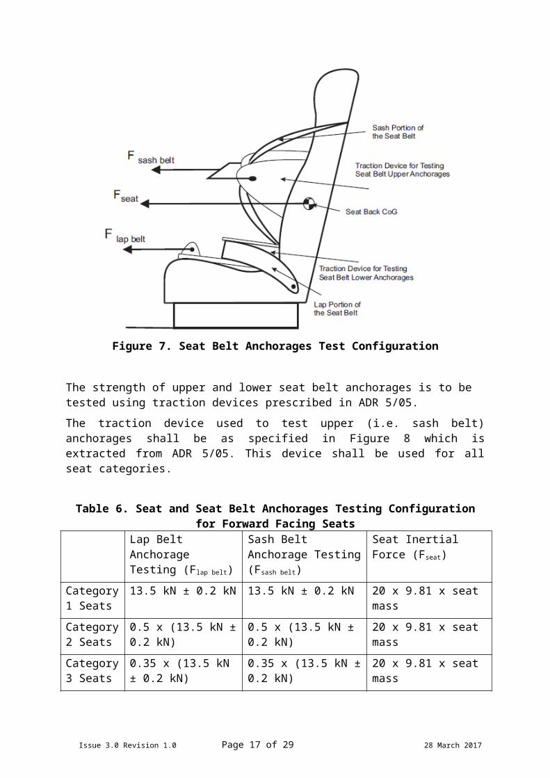
The strength of seat and seat belt anchorages on all forward facing seats must be tested in the configuration shown in Figure 7 to comply with the relevant requirements of ADR 3/--, ADR 5/-- and ADR 34/-- with the exception that the forces applied to the seat are adjusted according the category of the seats as in Table 6
Figure 7. Seat Belt Anchorages Test Configuration
The strength of upper and lower seat belt anchorages is to be tested using traction devices prescribed in ADR 5/05.
The traction device used to test upper (i.e. sash belt) anchorages shall be as specified in Figure 8 which is extracted from ADR 5/05. This device shall be used for all seat categories.
Issue 3.0 Revision 1.0 Page 14 of 24 28 March 2017
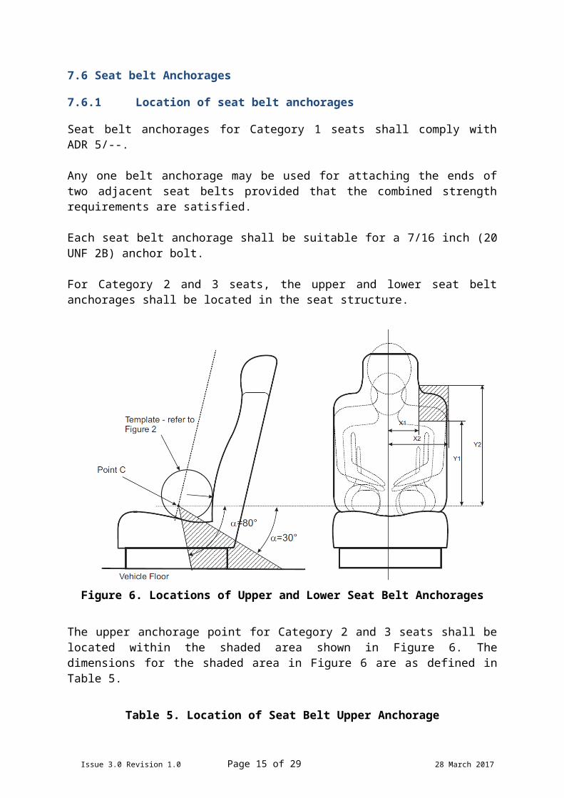
Table 6. Seat and Seat Belt Anchorages Testing Configuration for Forward Facing Seats
Lap Belt Anchorage Testing (Flap belt)
Sash Belt Anchorage Testing (Fsash belt)
Seat Inertial Force (Fseat)
Category 1 Seats
13.5 kN ± 0.2 kN 13.5 kN ± 0.2 kN 20 x 9.81 x seat mass
Category 2 Seats
0.5 x (13.5 kN ± 0.2 kN)
0.5 x (13.5 kN ± 0.2 kN)
20 x 9.81 x seat mass
Category 3 Seats
0.35 x (13.5 kN ± 0.2 kN)
0.35 x (13.5 kN ± 0.2 kN)
20 x 9.81 x seat mass
NOTE: Block covered by medium density canvas covered foam rubber at least 25mm thick.
Figure 8. Traction Device for Testing All Upper Seat belt Anchorages
Issue 3.0 Revision 1.0 Page 15 of 24 28 March 2017

NOTE: Block covered by medium density canvas covered foam rubber at least 25mm thick.
Figure 9. Traction Device for Testing Lower Seat Belt Anchorage for Category 2 or 3 seat
The device shown in Figure 9 is to be used for Category 2 and 3 seats. Category 1 seats are to be tested using a traction device with a width of 406 mm.
The seat must be able to withstand, without imposing any load on any other seat in the vehicle, a load equivalent to twenty times the weight of the seat applied in the rearward direction relative to the vehicle as shown in Figure 10.
Figure 10. Seat Rearward Test Configuration
Issue 3.0 Revision 1.0 Page 16 of 24 28 March 2017
7.7.3 Rearward-facing Seats
The strength of seat and seat belt anchorages on all rearward facing seats must be tested in the configuration shown in Figure 7 to comply with the relevant requirements of ADR 5/-- with the exception that the forces applied to the seat are adjusted according the category of the seats as listed in Table 7:
Table 7. Seat and Seat Belt Anchorages Testing Configuration for Rearward Facing Seats
Category of seat
Lap Belt Anchorage Testing (Flap belt)
Sash Belt Anchorage Testing (Fsash belt)
Seat Inertial Force (Fseat rearward)
Category 1 Seats
4.5 kN ± 0.2 kN 4.5 kN ± 0.2 kN 6.6 x 9.81 x seat mass
Category 2 Seats
0.5 x (4.5 kN ± 0.2 kN) 0.5 x (4.5 kN ± 0.2 kN) 6.6 x 9.81 x seat mass
Category 3 Seats
0.35 x (4.5 kN ± 0.2 kN) 0.35 x (4.5 kN ± 0.2 kN)
6.6 x 9.81 x seat mass
The seat must be able to withstand a load equivalent to twenty times the weight of the seat and its occupant(s) applied in the forward direction relative to the vehicle as shown in Figure 10.
7.8 Child Restraint Anchorage Points
Child restraint anchorages shall comply with the requirements of ADR 34/--.
Child restraint anchorages must not be installed to permit restraining devices such as rearward-facing and forward-facing restraints to be used on rear-facing seats.
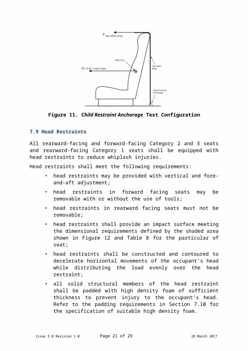
Where the Child restraint anchorages are located in or on the seat back, or in the vehicle body structure more than 100 mm below the top of the seat back longitudinally forward to the Child restraint anchorage, 20 times the mass of the entire seat in a forward longitudinal direction simultaneously with a load of 3.4 kN for each Child restraint anchorage must be imposed on the seat. The seat and anchorage point must be able to withstand these loads applied for at least one second.
Issue 3.0 Revision 1.0 Page 17 of 24 28 March 2017
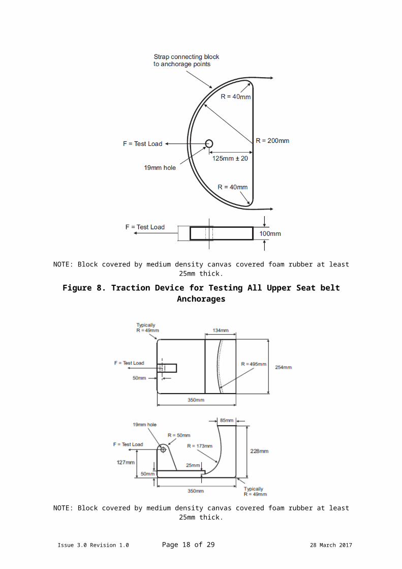
Figure 11. Child Restraint Anchorage Test Configuration
7.9 Head Restraints
All rearward-facing and forward-facing Category 2 and 3 seats and rearward-facing Category 1 seats shall be equipped with head restraints to reduce whiplash injuries.
Head restraints shall meet the following requirements:
• head restraints may be provided with vertical and fore-and-aft adjustment;
• head restraints in forward facing seats may be removable with or without the use of tools;
• head restraints in rearward facing seats must not be removable;
• head restraints shall provide an impact surface meeting the dimensional requirements defined by the shaded area shown in Figure 12 and Table 8 for the particular of seat;
• head restraints shall be constructed and contoured to decelerate horizontal movements of the occupant's head while distributing the load evenly over the head restraint;
• all solid structural members of the head restraint shall be padded with high density foam of sufficient thickness to prevent injury to the occupant's head. Refer to the padding requirements in Section 7.10 for the specification of suitable high density foam.
Issue 3.0 Revision 1.0 Page 18 of 24 28 March 2017

Figure 12. Dimensions of Head Restraints
Table 8. Minimum Dimensions of Head Restraints
DIMENSION CATEGORY 1 SEAT
CATEGORY 2 SEAT
CATEGORY 3 SEAT
E 750 mm 650 mm 560 mm
F 115 mm 115 mm 115 mm
G 250 mm 250 mm 250 mm
H 170 mm 170 mm 170 mm
The strength of the head restraints on all seats must be tested and shown in Figure13 to comply with the relevant requirements of ADR 3/-- with the exception that the applied 890 N force about point C specified for testing each seating position can be reduced for Category 2 and Category 3 seats to:
Category 2 Seats (0.5 x 890 =) 445 N;Category 3 Seats (0.35 x 890 =) 312 N.
A representative Head Form 165mm in diameter shall be used to assess the head restraint.
Issue 3.0 Revision 1.0 Page 19 of 24 28 March 2017
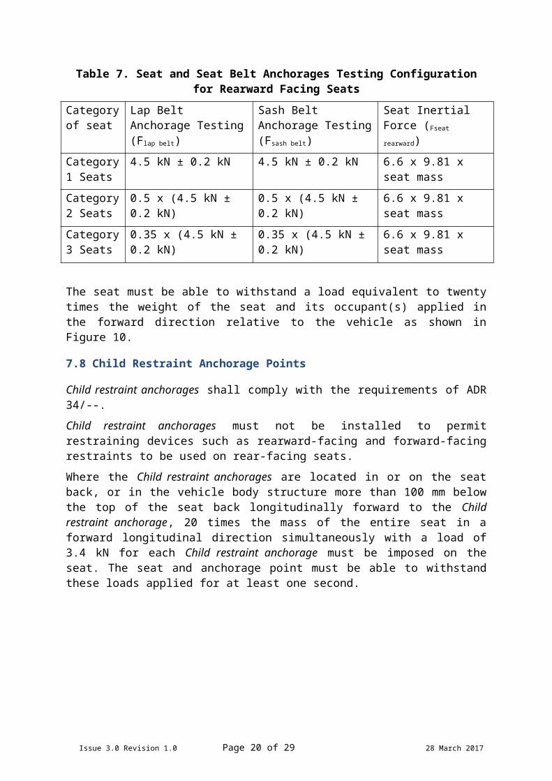
Figure 13. Head Restraint Test Configuration
A load corresponding to the seat category shall be applied to the head form at a point 65mm below the top of the head restraint.
The displacement of the rearmost point of the head form perpendicularly rearward of the displaced Torso Reference Line shall not exceed 102mm before the load exceeds 890N or the seat frame fails whichever first occurs first.
7.10 Padding
7.10.1 Seat Padding Requirements
Seat padding and upholstery must be securely attached to the seat frame to prevent movement during impact.
Loose cushions must not be used.
7.10.2 Energy Absorbing (Padded) Seat Backs
Energy absorbing material (padding) is required on all seats that have seats behind them, that is:
front row seats in vehicles with two rows;
front and second row seats in vehicles with three rows; and
front, second and third row seats in vehicles with four rows.
Energy absorbing material is not required on:
seats in vehicles with a single row of seats; or
seats installed back to back (i.e. when a rear facing seat is installed immediately behind a forward facing seat); and
The requirements for padding locations, test methods and type of material on the parts of the seat backs as per those required in Section LK of the Vehicle Standards Bulletin 14 with the exception the seat backs when tested according to the
Issue 3.0 Revision 1.0 Page 20 of 24 28 March 2017
requirements of ADR 3/02 Clause 6.4, the Head Injury Criterion (HIC) shall be less than 1000.
8 LABELLING AND MARKING OF SEATS
8.1 Manufacturer’s Labels and Installer’s Labels
Each Additional seat manufactured in accordance with this VSB 5 shall have a permanent manufacturer’s plate or label showing the name of the manufacturer and the date that the seat was manufactured. The plate or label shall be affixed in a conspicuous place on the seat.
An installer’s plate or label shall also be affixed in a conspicuous place on or near the seat.
If the seat’s manufacturer is also its installer, a single plate or label may be used. If a single plate or label is used, it shall state:
If the seat manufacturer is not the installer, the plates or labels shall state:
These plates or labels shall:
a) be made of a durable material which is not easily removed or defaced in normal use; and
b) display the required statements, clearly legible in characters at least 5mm high on a contrasting background.
Each Additional seat manufactured in accordance with this VSB 5 must also nominate - included in the instruction manual - the make(s) and model(s) of vehicle that the seat was designed for.
8.2 Usage Labels for Category 2 and 3 Seats
Category 2 and 3 seats must display the following warning label:
Issue 3.0 Revision 1.0 Page 21 of 24 28 March 2017
This seat was manufactured by (insert manufacturer’s name) on (insert build date) and installed on (insert installation date) in accordance with VSB 05(insert version number and year)
This seat was manufactured by (insert manufacturer’s name) on (insert build date) in accordance with VSB 05 (insert version number and year)
This seat was installed by (insert installer’s name) on (insert installation date) in accordance with VSB 05 (insert version number and year)

8.3 Shoulder Height Marking
Upper and lower Shoulder height markers shall be placed on Category 2 and 3 seats and shall meet the following requirements.
The marking shall be permanently fixed to the front of the seat back or otherwise permanently marked onto that surface;
The size of the label text box on the upper and lower shoulder marking shall be as defined in Figure 14 and 15 respectively.
The marking shall be positioned in close proximity to the expected occupant Shoulder height or as shown in Figure 16;
The marking shall be made from a durable material.
Figure 14. Upper Shoulder Marker
Figure 15. Lower Shoulder Marker
Locations of Lower Shoulder Height MarkerFor Category 2and 3 Seats, the horizontal centreline of the label shall be at 350±5mm above the surface of the seat cushion, measured on the centreline of the seating position, dimension X in Figure 16.
Locations of Upper Shoulder Height MarkerFor Category 2 Seats, the horizontal centreline of the label shall be at 490±5mm above the surface of the seat cushion, measured on the centreline of the seating position, dimension Y in Figure 16.
Issue 3.0 Revision 1.0 Page 22 of 24 28 March 2017
WARNINGTHIS SEAT MUST NOT BE USED BY A PERSON WITH A SHOULDER HEIGHT OUTSIDE THE INDICATED SHOULDER HEIGHT MARKING RANGE

For Category 3 Seats, the horizontal centreline of the label shall be at 410±5mm above the surface of the seat cushion, measured on the centreline of the seating position, dimension Y in Figure 16.
Figure 16. Locations of Shoulder Markers
Issue 3.0 Revision 1.0 Page 23 of 24 28 March 2017

APPENDIX A – DEFINITIONS
The following terms are used in this VSB 5.
Additional seats are the seats that change the seating capacity of the vehicle.
Australian Design Rules (ADRs) are mandatory vehicles safety, performance and environmental standards that apply to new vehicles supplied to the Australian market for use in road transport.
Child Restraint is a device to restrain a child passenger of a motor vehicle in the event of a vehicle impact and thus minimise the risk of bodily injury. It can be categorised in three major types of restraint being rearward facing restraint, forward facing restraint and booster seat.
Child Restraint Anchorage is the part of the vehicle designed to transfer loads from the upper part of the Child Restraint to the vehicle structure.
In-Service Vehicle means a motor vehicle that has been registered by a registering authority.
May indicates an option that is permissible and which does not affect compliance with this VSB 5 whether or not it is used.
Must indicates that something mandatory under legislation.
New Vehicle means a motor vehicle that has not been previously registered in Australia.
Seating Reference Point (SRP) is the vehicle manufacturer’s design reference point representing the position of the pivot centre of human torso and thigh for the rearmost normal design driving or riding position for each designated seating position in a vehicle.
Shall indicates something that is a mandatory to ensure compliance with this VSB 5.
Should indicates something that is recommended, but is not necessary to ensure compliance with this VSB 5.
Shoulder Height the vertical distance between a flat surface on which the person is seated and the top of the person's mid shoulder.
Station Wagon means a motor vehicle: body style variant of a sedan/saloon with its roof extended rearward over a shared passenger/cargo volume with access at the back via a third or fifth door and usually has one or more rows of folding or removable seats behind the driver to increase its load carrying capacity. Many MC Category vehicles are designated as station wagons.
Submarining is a phenomenon where the pelvis of the seat occupant slips forward under the lap belt in a frontal crash causing the lap belt to penetrate the soft abdomen of the occupant.
Torso Reference Line (TRL) is a line parallel to the seat back and passing through the Seating Reference Point. For seats with fully adjustable seat backs, it is a line inclined no more than 30 degrees to the vertical.
Issue 3.0 Revision 1.0 Page 24 of 24 28 March 2017