Embed Size (px)
Citation preview
TABLE OF CONTENTS
TABLE OF CONTENTS......................................1
INTRODUCTION................................................1
Digital LCD Pressure Gauge................................1
Feature...................................................................1
Specifications.........................................................2
APPLICATION ..................................................... 2
Digital LCD Pressure Gauge Operation ............. 3
STANDARD PARTS LIST ................................... 3
SAFETY PRECAUTIONS ................................... 4
VEHICLE SERVICE MANUALS......................6
FUEL PRESSURE DIAGNOSIS.........................7
HIGHER THAN NORMAL PRESSURE ........... 7
MAINTAINING SYSTEM PRESSURE.............7
WIPE UP ANY FUEL LEAKS IMMEDIATELY.9
RELIEVING SYSTEM FUEL PRESSURE ....... 9
SELECTING ADAPTORS - CONNECTING TO THE FUEL SYSTEM.........................................10
TEST PORT CONNECTIONS..........................10
IN-LINE TEE CONNECTIONS ...................... 10
Key On Engine Off Test ...................................... 11
Key On Engine On Test......................................12
In line Banjo Bolt connection ............................. 13
THREADED CONNECTIONS - STANDARD 14
THREADED CONNECTIONS - BANJO WHEN IN-LINE FLOWCONTROL VALVE IS REQUIRED. ........................................................ 15
CONNECTING TO CIS (K-JETRONIC) MECHANICAL SYSTEMS ............................... 16

INTRODUCTIONCongratulations. You have purchased a precision digital instrument manufactured to the highest quality standards. The ADD600 Fuel Injection Pressure Digital Tester Kit is designed to perform fuel pressure tests on most domestic and imported cars and trucks that are equipped with electronic fuel injection systems. The Tester Kit provides the professional automotive technician with a fast and accurate way to test and identify system faults on both mechanical (CIS) and electronic (EFi) injection systems on a large range of vehicles worldwide.The kit includes a comprehensive range of adaptors to effect 'In-Line' system connections, including 'Tee', 'Banjo Bolt', 'Test Port' and Threaded adaptors to allow fitting onto the many and various fuel injection systems likely to be encountered.The Gauge and Hose Assembly features a precision digital pressure gauge designed for accuracy, even in the lower pressure ranges to cover some SPi systems, an extra-long connection hose for improved practical use and long see-thru bleed hose for relieving fuel system pressure away from the vehicle.Both male and female coupler connections are 'Valved' for safety and to minimize the risk of fuel spray and spillage.The tester can help you identify and diagnose:• Low OR High fuel pressure • Leaking fuel injectors• Faulty fuel pressure regulator • Clogged fuel filter• Leaks in the fuel system • Faulty fuel pump
Digital LCD Pressure Gauge
Feature1.Burst pressure: 300% F.S.2.Proof pressure: 200% F.S.3.Accuracy ± 0.3% ± 1 digit @25oC4.Resolution is better than 0.1%5.Four digits LCD display6.Dual-polarity value display7.User zeroing8.Auto-off function9.Typical battery life is over 1500 times(each time180
seconds)10. Low battery indication11. Rubber shroud protection12. Software calibration13. Standards used in this calibration are traceable to the
National Institute of Standards Technology (NIST).14. Digital calibration and setting data stored in EEPROM15. Function
Continuous reading vs. Peak & hold selectable Always on vs. Auto-off selectable Auto-off time selectable Four units selectable
Pressure gauge: PSI, BAR, kgf/cm2, kPaVacuum gauge: in.Hg, mBar, Torr, hPa
Maximum display value setting Minimum display value setting
1
Specifications1.Sensor type: Silicon sensor2.Pressure range: 0~100 PSI3.Display pressure range: 0~120% F.S.4.Proof pressure: 200% F.S.5.Media: Non-corrosive liquids and gases6.Display: 4 Digits TN type LCD7.Supply voltage: 9 V DC battery8.Battery life: 1500 times typical “ON” time9.Low battery indication: “ ”= replace battery10. Current consumption: 6mA maximum11. Standby current: 5µ A maximum12. User interface: ON, ZERO13. Operating temperature: 0 ~ 45 (32 ~ 115 )℃ ℉14. Storage temperature: -10 ~ 75 (15 ~ 165 )℃ ℉15. Accuracy: ± 0.3% ± 1 digit @25 ℃16. Thermal error: ± 1% of Full Scale
WARING: Digital Pressure Gauge only be used in medium of gasoline Don’t test the other liquid otherwise it will damage the gauge.
APPLICATIONA wide range of GASOLINE fuel injection systems including:
Bosch: K, KE, KE3, L, LE2, LE3, LH. Jetronic.Bosch Motronic: M1.3, M1.7, M2.5, M3.1,ML4.1, MA3.0, A2.2 SPi. Bendix-Fenix: EFi.Chrysler: SM. Daihatsu: EFi.
Fiat: SPi, Weber 1AW. Ford: EEC1V, EFi, Weber CFi. GM: Multec SPi, EFi, Simtec EFi.Hyundai: EFi. Honda: PGM-Fi.Isuzu: 1-Tec. Kia: EFi.Lucas: L Hotwire, P Digital.Magnet Marelli: EFi, G5/G6 Mono.Mazda: EGi. Mitsubishi: ECi, MPi.Nissan: EFi, ECCS. Renault: R Electronic.Renix: MPi. Rover: SPi, PGM-Fi, M.E.M.S.Subaru: MPFi, SPFi.Suzuki: E.Toyota: EFi, TCCS.VW: Digijet, Digifant, VAG MPi.Weber-Marelli: 1AW, CFi.
2
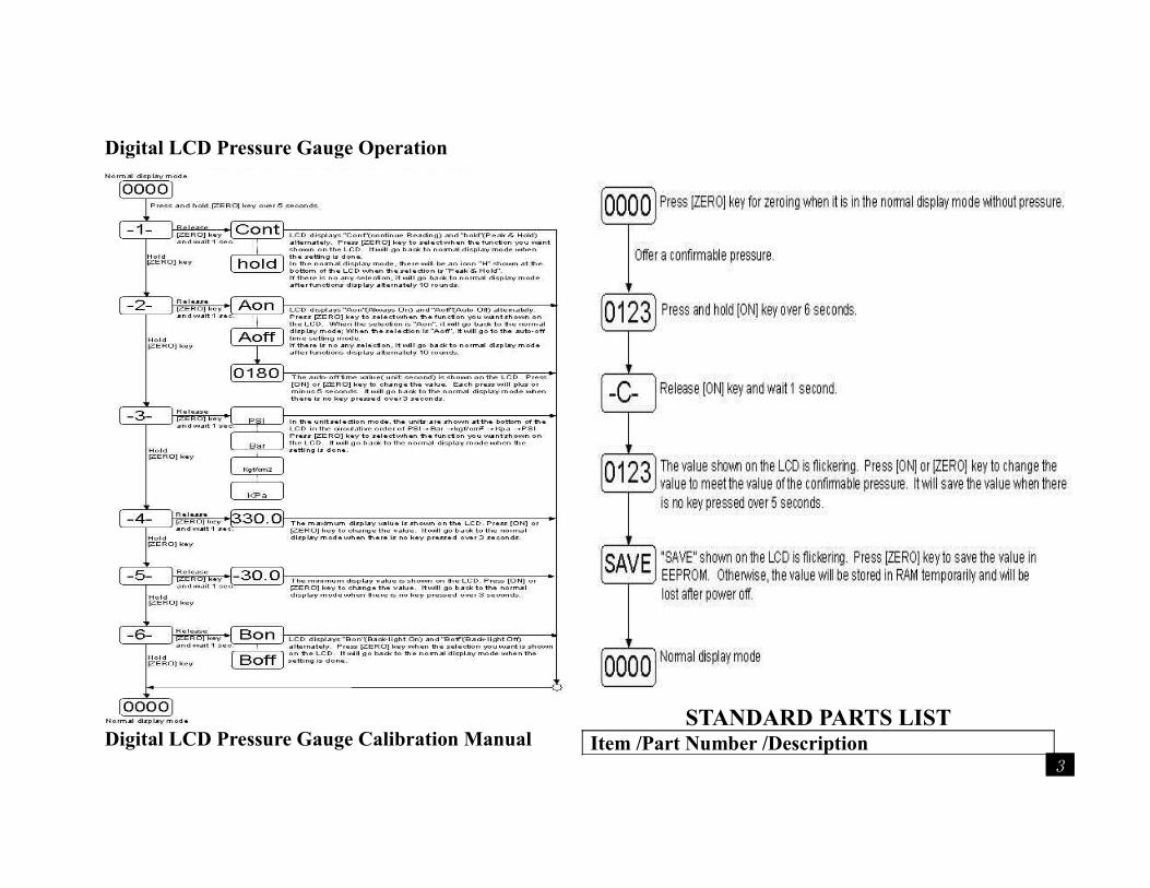
Digital LCD Pressure Gauge Operation
Digital LCD Pressure Gauge Calibration Manual
STANDARD PARTS LISTItem /Part Number /Description
3
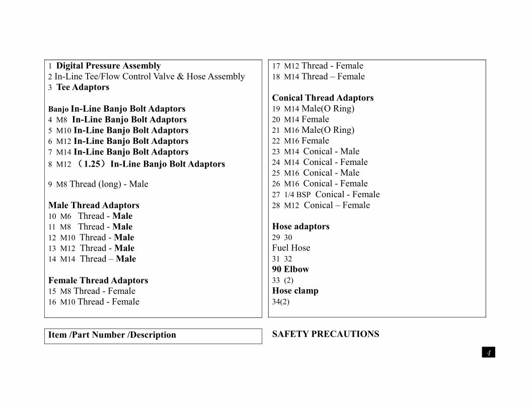
1 Digital Pressure Assembly2 In-Line Tee/Flow Control Valve & Hose Assembly3 Tee Adaptors
Banjo In-Line Banjo Bolt Adaptors4 M8 In-Line Banjo Bolt Adaptors5 M10 In-Line Banjo Bolt Adaptors6 M12 In-Line Banjo Bolt Adaptors7 M14 In-Line Banjo Bolt Adaptors8 M12 (1.25)In-Line Banjo Bolt Adaptors
9 M8 Thread (long) - Male
Male Thread Adaptors10 M6 Thread - Male11 M8 Thread - Male12 M10 Thread - Male13 M12 Thread - Male14 M14 Thread – Male
Female Thread Adaptors15 M8 Thread - Female16 M10 Thread - Female
Item /Part Number /Description
17 M12 Thread - Female18 M14 Thread – Female
Conical Thread Adaptors19 M14 Male(O Ring) 20 M14 Female21 M16 Male(O Ring)22 M16 Female23 M14 Conical - Male24 M14 Conical - Female25 M16 Conical - Male26 M16 Conical - Female27 1/4 BSP Conical - Female28 M12 Conical – Female
Hose adaptors29 30 Fuel Hose31 32 90 Elbow33 (2) Hose clamp34(2)
SAFETY PRECAUTIONS
4
To avoid personal injury, instrument damage and/or damage to equipment under test, DO NOT operates the tester before reading this manual.Always use extreme caution when working on an automobile. This manual describes common test procedures used by experienced service personnel and technicians. Many test procedures require precautions to avoid accidents that can result in personal injury, and/or vehicle or equipment damage. Always read your vehicle's service manual and follow it’s safety precautions before any test or procedure is performed.
a. When an engine is in operation, it produces carbon monoxide (a toxic and poisonous gas). To prevent serious injury or death from carbon monoxide poisoning, operate a vehicle only in a well-ventilated area.
b. To protect your eyes from propelled objects as well as hot or caustic liquids, always wear approved safety eye protection.
c. When an engine is running, several engine components rotate at a very high rate of speed (coolant fan, pulleys, fan belt, etc.). To avoid serious injury, always be conscious of moving parts and keep a safe distance from all these items as well as other potentially moving objects.
d. Engine parts become extremely hot when the engine is running. To prevent severe burns, avoid contact with hot engine parts.
e. Before starting an engine for troubleshooting, make sure the parking brakes engaged. Put the transmission in “park” (for automatic transmission) or “Neutral” (for manual transmission). Block the drive wheels with a suitable blocking device.
f. Never leave a vehicle unattended during testing.
g. When working on vehicles equipped with airbags, follow all cautions and test procedures in your vehicle's service manual to avoid accidental airbag Deployment.
h. Don't wear loose clothing or jewelry when working on an engine. Loose clothing can get caught on the fan, pulleys, belts, etc. Jewelry is highly conductive to electricity, and can cause a severe burn if it makes contact between a power source and ground.
The following safety precautions apply to fuel and fuel systems. Gasoline is an extremely flammable substance. To prevent fires and/or severe burns, always take extra precautions when troubleshooting or working on fuel systems.
i. Gasoline and battery vapors are highly flammable. To prevent an explosion or fire, keep all sparks, high temperature items or open flames away from gasoline/gasoline vapors and battery. DO NOT SMOKE NEAR THE VEHICLE DURING TESTING.
j. Gasoline and gasoline additives are toxic. AVOID CONTACT OF GASOLINE WITH SKIN. Wear protective clothing and hand covering (approved latex gloves) when performing pressure tests. In case of contact with skin, WASH THE AREA IMMEDIATELY and perform any other necessary first aid.
k. In case of emergency, keep a fire extinguisher handy. MAKE SURE it is rated for fuel/electrical and chemical fires.
l. During testing, be careful to avoid fuel spills on hot engine parts. If spills occur or if leaks are present, turn ignition off IMMEDIATELY and correct the problem. WIPE UP FUEL SPELLS IMMEDIATELY.
m. When placing the bleed-off hose into a container to collect
5
excess fuel, MAKE SURE the container is approved for gasoline.
VEHICLE SERVICE MANUALSYou must consult the manufacturer's service manual for your vehicle BEFORE performing any test procedures. Contact your local car dealership, auto parts store, bookstore, or public library for availability of these manuals.
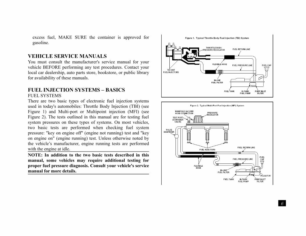
FUEL INJECTION SYSTEMS – BASICSFUEL SYSTEMSThere are two basic types of electronic fuel injection systems used in today's automobiles: Throttle Body Injection (TBI) (see Figure 1) and Multi-port or Multipoint injection (MFI) (see Figure 2). The tests outlined in this manual are for testing fuel system pressures on these types of systems. On most vehicles, two basic tests are performed when checking fuel system pressure: "key on engine off" (engine not running) test and "key on engine on" (engine running) test. Unless otherwise noted by the vehicle’s manufacturer, engine running tests are performed with the engine at idle.NOTE: In addition to the two basic tests described in this manual, some vehicles may require additional testing for proper fuel pressure diagnosis. Consult your vehicle's service manual for more details.
6
FUEL PRESSURE DIAGNOSISThe Fuel Injection System Pressure Test Kit is used to identify system faults via system pressure readings and fuel delivery rate.Faults such as: Blocked lines Blocked filters Reduced output from pump Faulty regulatorFuel pressure is affected by the condition of the fuel pipes and components that make up the supply and return sides of the system. Lower than normal pressure is usually due to a faulty supply side component. Higher than normal pressure is usually caused by a faulty return side component. A fault in the fuel pressure regulator could result in higher or lower pressure, since it divides the supply from the return side.
HIGHER THAN NORMAL PRESSUREUsually attributed to faults such as defective fuel pressure regulator,restriction (bend or kink) in return line or excessive tank pressure caused by a poor vent system. Isolate the area of restriction by disconnecting the fuel return pipe starting from the pressure regulator (only after relieving system pressure). Both outlets from the disconnection must be routed to a fuel container. Operate the fuel system and if the pressure is at the specified level when the regulator is functioning normally, then the restriction is between the disconnected return pipe and the tank. If the pressure remains high the regulator may be defective.
MAINTAINING SYSTEM PRESSUREMost fuel injection systems will maintain the fuel pressure after
the engine has been switched off to ensure fuel for easier starting. If this pressure leaks the vehicle may be hard to start.ATING INSTRUCTIONS
WARNING! Ensure you have read, understood and apply the AFETYPRECAUTIONS. Before using tools.
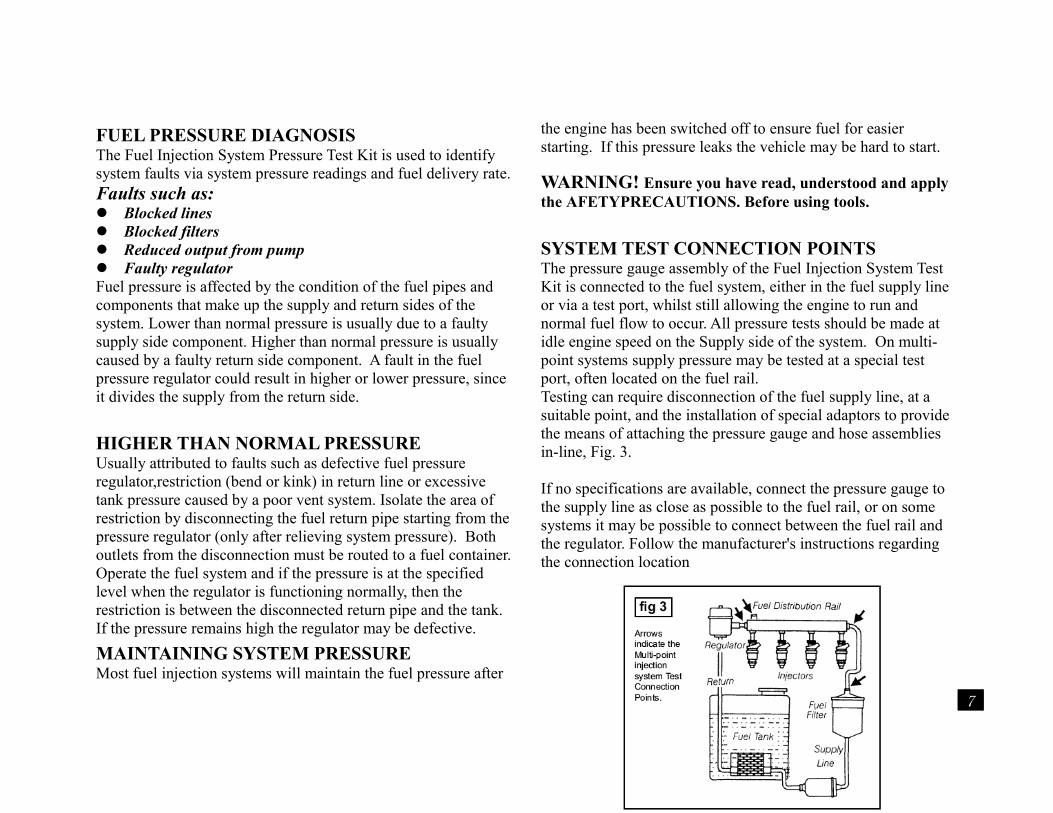
SYSTEM TEST CONNECTION POINTS The pressure gauge assembly of the Fuel Injection System Test Kit is connected to the fuel system, either in the fuel supply line or via a test port, whilst still allowing the engine to run and normal fuel flow to occur. All pressure tests should be made at idle engine speed on the Supply side of the system. On multi-point systems supply pressure may be tested at a special test port, often located on the fuel rail.Testing can require disconnection of the fuel supply line, at a suitable point, and the installation of special adaptors to provide the means of attaching the pressure gauge and hose assemblies in-line, Fig. 3.
If no specifications are available, connect the pressure gauge to the supply line as close as possible to the fuel rail, or on some systems it may be possible to connect between the fuel rail and the regulator. Follow the manufacturer's instructions regarding the connection location
7
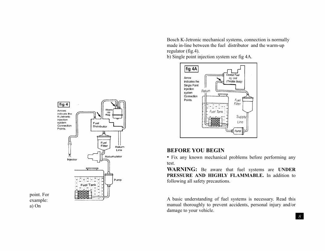
point. For example: a) On
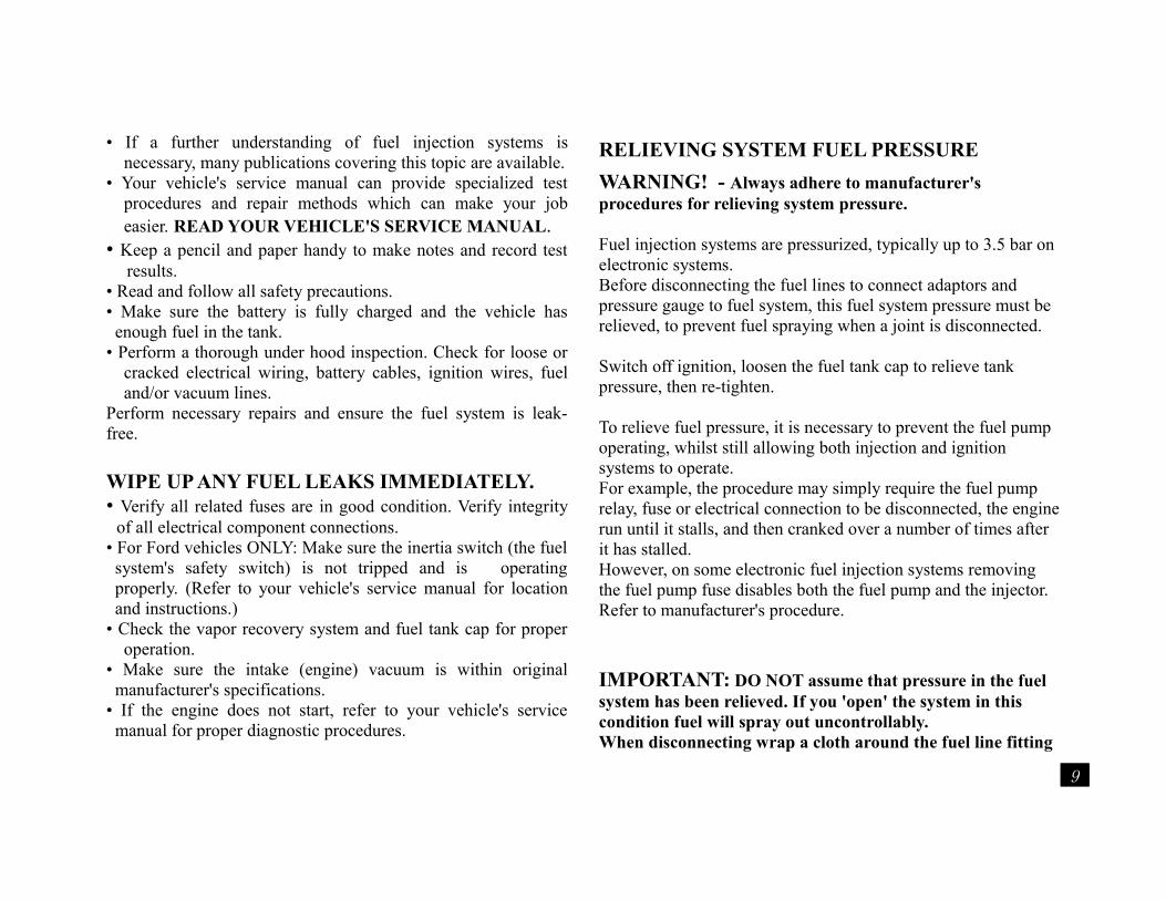
Bosch K-Jetronic mechanical systems, connection is normally made in-line between the fuel distributor and the warm-up regulator (fig.4).b) Single point injection system see fig 4A.
BEFORE YOU BEGIN• Fix any known mechanical problems before performing any test.WARNING: Be aware that fuel systems are UNDER PRESSURE AND HIGHLY FLAMMABLE. In addition to following all safety precautions.
A basic understanding of fuel systems is necessary. Read this manual thoroughly to prevent accidents, personal injury and/or damage to your vehicle.
8
• If a further understanding of fuel injection systems is necessary, many publications covering this topic are available.
• Your vehicle's service manual can provide specialized test procedures and repair methods which can make your job easier. READ YOUR VEHICLE'S SERVICE MANUAL.
• Keep a pencil and paper handy to make notes and record test results.
• Read and follow all safety precautions.• Make sure the battery is fully charged and the vehicle has enough fuel in the tank.
• Perform a thorough under hood inspection. Check for loose or cracked electrical wiring, battery cables, ignition wires, fuel and/or vacuum lines.
Perform necessary repairs and ensure the fuel system is leak-free.
WIPE UP ANY FUEL LEAKS IMMEDIATELY.• Verify all related fuses are in good condition. Verify integrity
of all electrical component connections.• For Ford vehicles ONLY: Make sure the inertia switch (the fuel system's safety switch) is not tripped and is operating properly. (Refer to your vehicle's service manual for location and instructions.)
• Check the vapor recovery system and fuel tank cap for proper operation.
• Make sure the intake (engine) vacuum is within original manufacturer's specifications.
• If the engine does not start, refer to your vehicle's service manual for proper diagnostic procedures.
RELIEVING SYSTEM FUEL PRESSURE
WARNING! - Always adhere to manufacturer's procedures for relieving system pressure.
Fuel injection systems are pressurized, typically up to 3.5 bar on electronic systems. Before disconnecting the fuel lines to connect adaptors and pressure gauge to fuel system, this fuel system pressure must be relieved, to prevent fuel spraying when a joint is disconnected.
Switch off ignition, loosen the fuel tank cap to relieve tank pressure, then re-tighten.
To relieve fuel pressure, it is necessary to prevent the fuel pump operating, whilst still allowing both injection and ignition systems to operate.For example, the procedure may simply require the fuel pump relay, fuse or electrical connection to be disconnected, the engine run until it stalls, and then cranked over a number of times after it has stalled. However, on some electronic fuel injection systems removing the fuel pump fuse disables both the fuel pump and the injector. Refer to manufacturer's procedure.
IMPORTANT: DO NOT assume that pressure in the fuel system has been relieved. If you 'open' the system in this condition fuel will spray out uncontrollably. When disconnecting wrap a cloth around the fuel line fitting
9
to absorb any fuel leakage.
SELECTING ADAPTORS - CONNECTING TO
THE FUEL SYSTEM.Vehicle, engine and fuel system combinations vary and change over time and specific adaptor applications are difficult to detail. The objective of the adaptor range is to provide the technician with the means of connecting the pressure gauge assembly onto a suitable place on the 'supply’ side of the fuel system, (normally between the fuel filter and fuel rail), in order to carry out system pressure tests/diagnosis.The ADD600 Kit provides a wide selection and combination of adaptors allowing connections to be made onto all known major systems. In addition the range of adaptors has been designed to provide variations and alternative methods of achieving entry into the fuel system, such as the In-Line Banjo Bolt Adaptors.
A guide to selection and use of the various types ofadaptors is detailed as follows:
When the pressure gauge assembly has been connected to the system, air must be bled from it using the bleed-off relief valve/hose situated directly under the gauge.
TEST PORT CONNECTIONSSystem examples: Bosch EFi/Motronic, Lucas EFi, Chrysler SM Some F.I. systems have Test Ports - a male fitting with internal schader type valve, very often located on the fuel rail.
These probably provide the most straightforward pressure test connection to a fuel injection systemTest Port connection are commonly found - 'Standard' - of the type on GM systems.
onto the test port and provide the valved coupler to connect the pressure gauge/hose directly onto the system (fig 5).Sealy Test Port Adaptors are 'Flexible' to aid connection in 'difficult to access' applications and 'Valved' at coupler end to minimize connection spray/fuel spillage.
IN-LINE TEE CONNECTIONS System examples: osch EFi, Nissan EFi/ECCS, Renix, Subaru MPFi, Toyota EFi/TCCS, VW Digijet, Ford CFi, Weber 1AWWARNING: Systems using the Tee adapter require that fuel lines be removed or disconnected. Be aware that these lines may be UNDER VERYHIGH PRESSURE and, when removed or disconnected, may cause fuel spray and/or leakage onto hot engine parts. Fuel system pressure testing requires procedures and precautions that are specific to the vehicle under test. To prevent serious accidents, and to perform an accurate fuel system pressure test, you must consult the vehicle’s service manual for roper service procedures and specifications.• The "Tee Adapter" included in the kit is intended for use on vehicles that don’t come factory equipped with fuel pressure test ports (Schrader Valves) or removable Fuel System Pressure Fittings. The Tee Adapter can only be used on vehicles that are equipped with flexible (rubber) fuel supply lines that facilitate
10
the installation of the Tee Adapter. The Tee Adapter is not suitable for use on fuel injection systems that are equipped with rigid, metallic or plastic lines or connectors. These systems require special tools and adapters to perform fuel pressure testing. Consult the vehicle's service manual for tool availability and test procedures for these vehicles.
a. Refer to the "Tee Adapter Application’s information on your specific year, make and model of vehicle. If your vehicle is on the list: Consult your vehicle's
service manual for procedures and to confirm the Tee adapter installation location.
If your vehicle is not on the list: You may still be able to use the Tee Adapter. Consult your vehicle’s service manual to determine if your vehicle is equipped with flexible rubber fuel supply lines that facilitate the use of the Tee Adapter.
b. Relieve fuel system pressure BEFORE disconnecting the fuel lines. (Refer to your vehicle's service manual for procedures.)
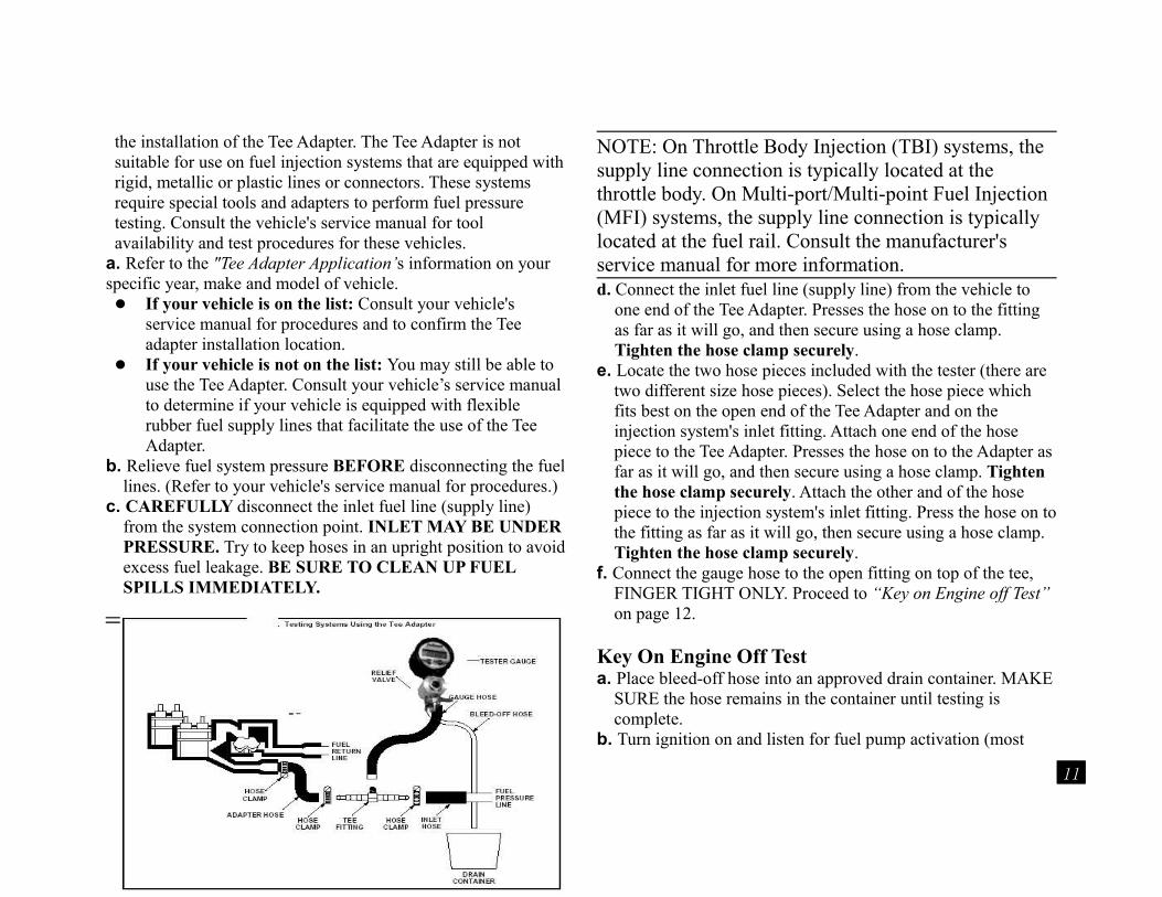
c. CAREFULLY disconnect the inlet fuel line (supply line) from the system connection point. INLET MAY BE UNDER PRESSURE. Try to keep hoses in an upright position to avoid excess fuel leakage. BE SURE TO CLEAN UP FUEL SPILLS IMMEDIATELY.
NOTE: On Throttle Body Injection (TBI) systems, the supply line connection is typically located at the throttle body. On Multi-port/Multi-point Fuel Injection (MFI) systems, the supply line connection is typically located at the fuel rail. Consult the manufacturer's service manual for more information.d. Connect the inlet fuel line (supply line) from the vehicle to
one end of the Tee Adapter. Presses the hose on to the fitting as far as it will go, and then secure using a hose clamp. Tighten the hose clamp securely.
e. Locate the two hose pieces included with the tester (there are two different size hose pieces). Select the hose piece which fits best on the open end of the Tee Adapter and on the injection system's inlet fitting. Attach one end of the hose piece to the Tee Adapter. Presses the hose on to the Adapter as far as it will go, and then secure using a hose clamp. Tighten the hose clamp securely. Attach the other and of the hose piece to the injection system's inlet fitting. Press the hose on to the fitting as far as it will go, then secure using a hose clamp. Tighten the hose clamp securely.
f. Connect the gauge hose to the open fitting on top of the tee, FINGER TIGHT ONLY. Proceed to “Key on Engine off Test” on page 12.
Key On Engine Off Testa. Place bleed-off hose into an approved drain container. MAKE
SURE the hose remains in the container until testing is complete.
b. Turn ignition on and listen for fuel pump activation (most
11
systems will activate the fuel pump circuit for approximately two seconds when the ignition is initially turned on to prime the fuel system). Check the test set-up and MAKE SURE no fuel leaks are present.
If fuel leaks are present, turn off ignition IMMEDIATELY and repair.
BE SURE TO CLEAN UP FUEL SPILLS IMMEDIATELY.
NOTE: If your fuel system does not operate as described in step b, or if the fuel system is not operating properly, refer to the manufacturer's service manual for repair procedures and/or activation instructions.c. When the fuel pump has been activated, the fuel system is
pressurized. Verify the tester gauge indicates a system pressure, which corresponds with the specifications provided in your vehicle's service manual. If the fuel pressure is within vehicle manufacturer's specifications, proceed to step “Key on Engine on Test” below. If pressure is not within manufacturer's specifications, proceed to step d.
d. Follow the test and repair procedures in your vehicle's service manual to correct the problem. After all necessary repairs have been completed, return to step a.
Key On Engine On Testa. Start and idle the engine. RECHECK THE TEST SET-UP
FOR FUELLEAKS and repair as necessary.b. Read fuel pressure from the tester gauge. If the fuel pressure
is within vehicle manufacturer's specifications proceed to step
d. If pressure is not within manufacturer's specifications, proceed to step c.
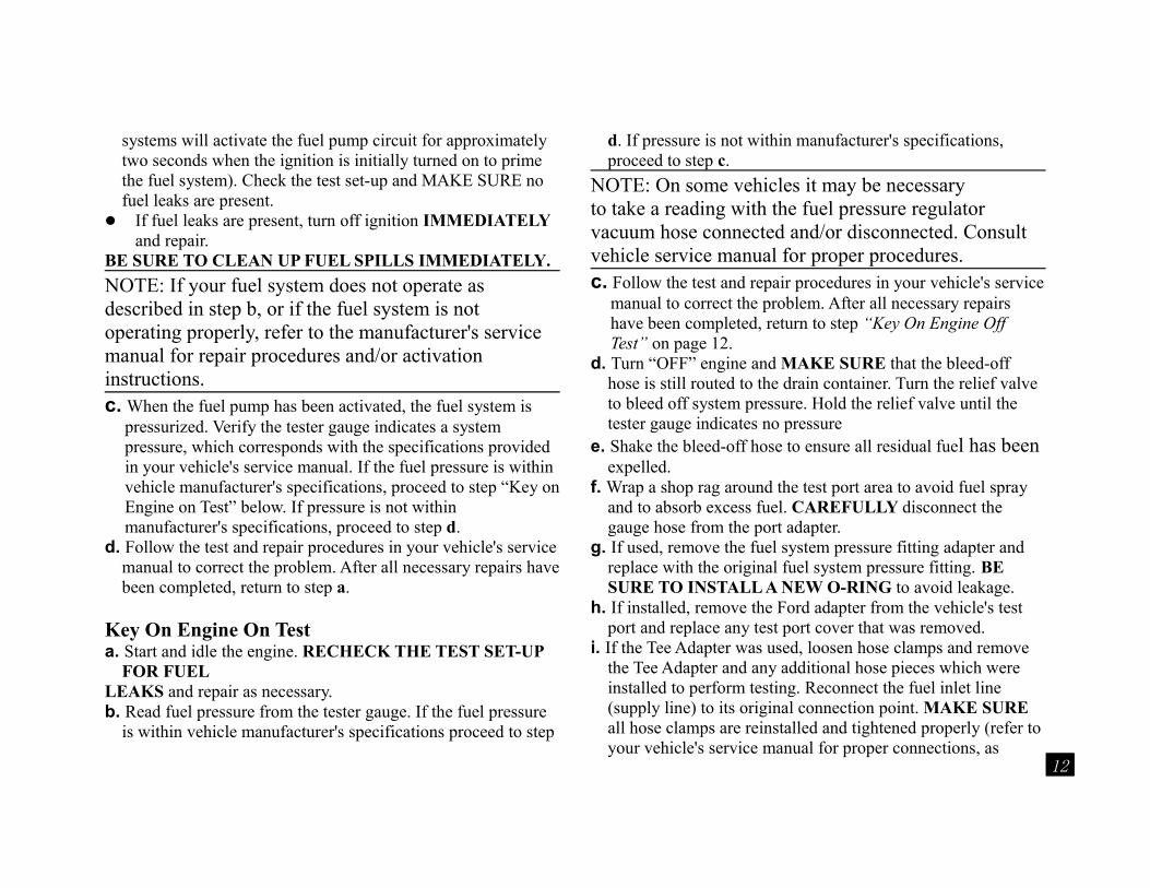
NOTE: On some vehicles it may be necessaryto take a reading with the fuel pressure regulator vacuum hose connected and/or disconnected. Consult vehicle service manual for proper procedures.c. Follow the test and repair procedures in your vehicle's service
manual to correct the problem. After all necessary repairs have been completed, return to step “Key On Engine Off Test” on page 12.
d. Turn “OFF” engine and MAKE SURE that the bleed-off hose is still routed to the drain container. Turn the relief valve to bleed off system pressure. Hold the relief valve until the tester gauge indicates no pressure
e. Shake the bleed-off hose to ensure all residual fuel has been expelled.
f. Wrap a shop rag around the test port area to avoid fuel spray and to absorb excess fuel. CAREFULLY disconnect the gauge hose from the port adapter.
g. If used, remove the fuel system pressure fitting adapter and replace with the original fuel system pressure fitting. BE SURE TO INSTALL A NEW O-RING to avoid leakage.
h. If installed, remove the Ford adapter from the vehicle's test port and replace any test port cover that was removed.
i. If the Tee Adapter was used, loosen hose clamps and remove the Tee Adapter and any additional hose pieces which were installed to perform testing. Reconnect the fuel inlet line (supply line) to its original connection point. MAKE SURE all hose clamps are reinstalled and tightened properly (refer to your vehicle's service manual for proper connections, as
12
necessary).j. Remove the bleed-off hose from the drain container and hold
both gauge hoses over the container to let any remaining fuel drain. Store the tester in a well-ventilated area to dry completely.
k. Recheck all fuel system connections, then start the engine. Check for any leaks and repair as necessary.
NOTES:• The engine may crank for several seconds before restarting.• Shop rags that have been exposed to any flammable liquids
or materials (gasoline, etc.) should be stored in an approved container to avoid hazardous conditions.
• The service life of the port adapter o-rings can be prolonged by applying a film of oil to them before storing.
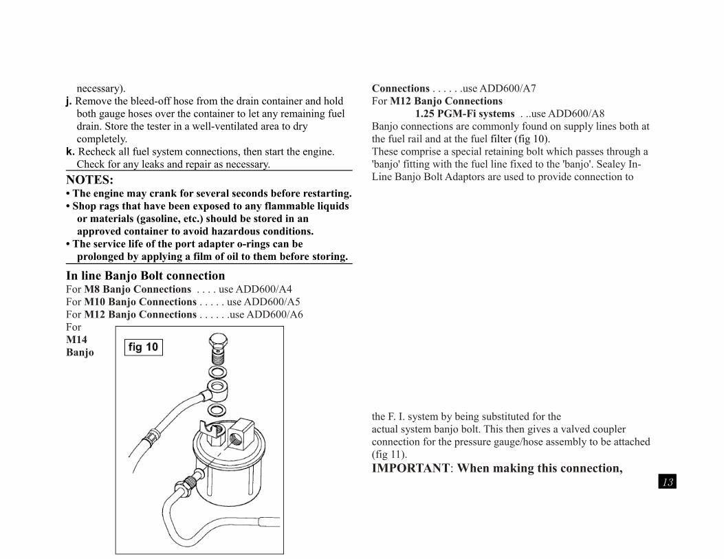
In line Banjo Bolt connectionFor M8 Banjo Connections . . . . use ADD600/A4For M10 Banjo Connections . . . . . use ADD600/A5For M12 Banjo Connections . . . . . .use ADD600/A6For M14 Banjo
Connections . . . . . .use ADD600/A7For M12 Banjo Connections
1.25 PGM-Fi systems . ..use ADD600/A8Banjo connections are commonly found on supply lines both at the fuel rail and at the fuel filter (fig 10).These comprise a special retaining bolt which passes through a 'banjo' fitting with the fuel line fixed to the 'banjo'. Sealey In-Line Banjo Bolt Adaptors are used to provide connection to
the F. I. system by being substituted for theactual system banjo bolt. This then gives a valved coupler connection for the pressure gauge/hose assembly to be attached (fig 11).IMPORTANT: When making this connection,
13
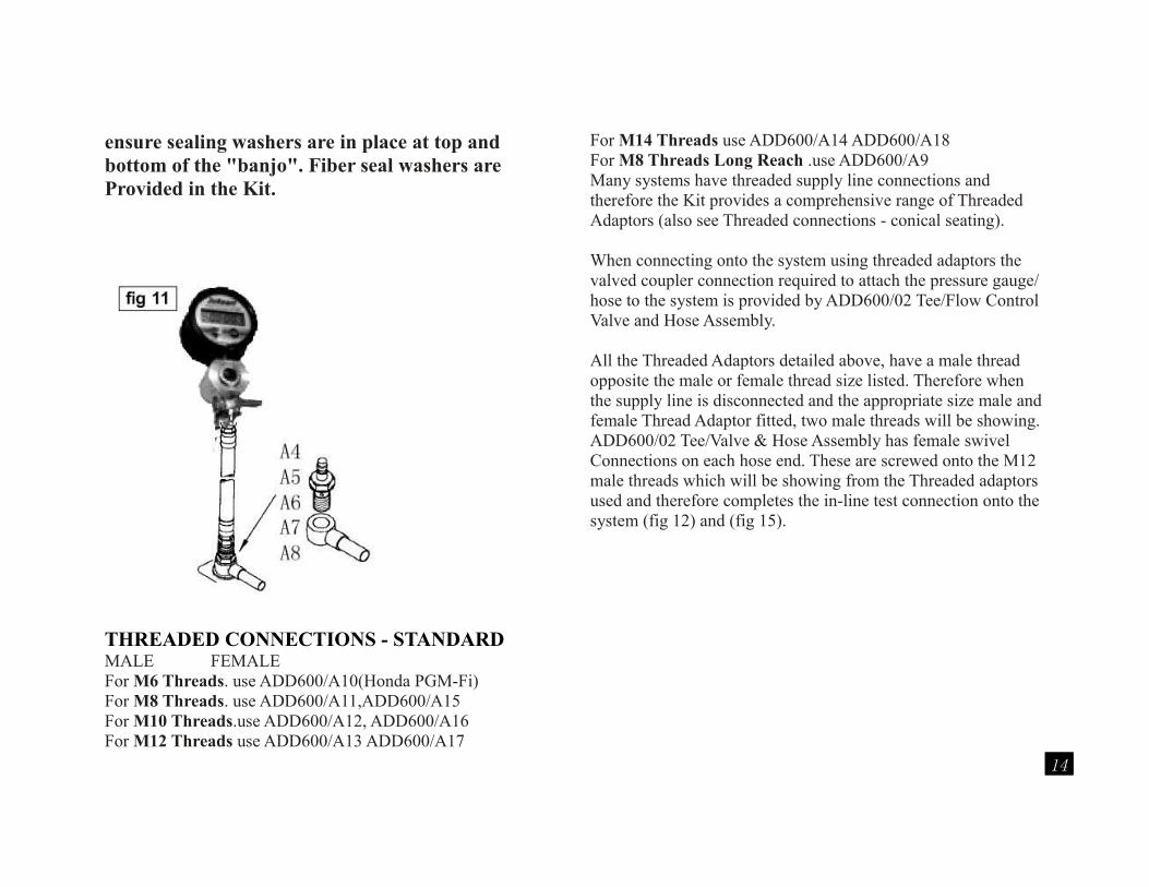
ensure sealing washers are in place at top and bottom of the "banjo". Fiber seal washers areProvided in the Kit.
THREADED CONNECTIONS - STANDARDMALE FEMALEFor M6 Threads. use ADD600/A10(Honda PGM-Fi) For M8 Threads. use ADD600/A11,ADD600/A15For M10 Threads.use ADD600/A12, ADD600/A16For M12 Threads use ADD600/A13 ADD600/A17
For M14 Threads use ADD600/A14 ADD600/A18For M8 Threads Long Reach .use ADD600/A9Many systems have threaded supply line connections and therefore the Kit provides a comprehensive range of Threaded Adaptors (also see Threaded connections - conical seating).
When connecting onto the system using threaded adaptors the valved coupler connection required to attach the pressure gauge/hose to the system is provided by ADD600/02 Tee/Flow Control Valve and Hose Assembly.
All the Threaded Adaptors detailed above, have a male thread opposite the male or female thread size listed. Therefore when the supply line is disconnected and the appropriate size male and female Thread Adaptor fitted, two male threads will be showing.ADD600/02 Tee/Valve & Hose Assembly has female swivelConnections on each hose end. These are screwed onto the M12 male threads which will be showing from the Threaded adaptors used and therefore completes the in-line test connection onto the system (fig 12) and (fig 15).
14
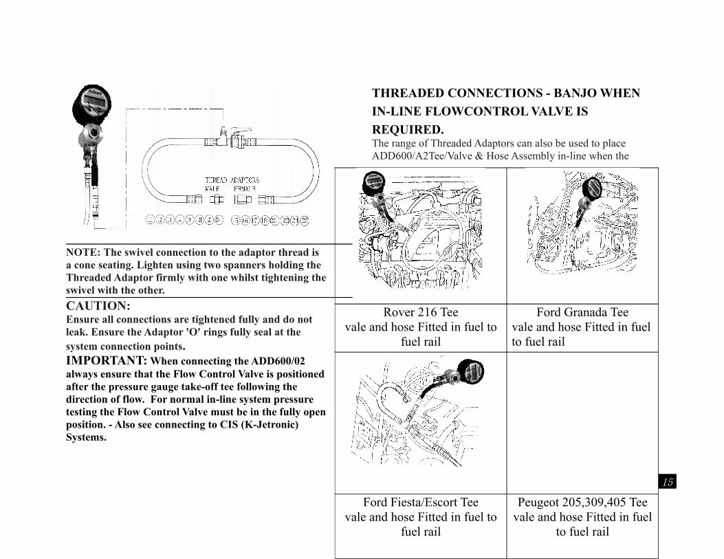
NOTE: The swivel connection to the adaptor thread is a cone seating. Lighten using two spanners holding the Threaded Adaptor firmly with one whilst tightening the swivel with the other.
CAUTION:Ensure all connections are tightened fully and do not leak. Ensure the Adaptor 'O' rings fully seal at the system connection points.IMPORTANT: When connecting the ADD600/02 always ensure that the Flow Control Valve is positioned after the pressure gauge take-off tee following the direction of flow. For normal in-line system pressure testing the Flow Control Valve must be in the fully open position. - Also see connecting to CIS (K-Jetronic) Systems.
THREADED CONNECTIONS - BANJO WHEN
IN-LINE FLOWCONTROL VALVE IS
REQUIRED.The range of Threaded Adaptors can also be used to place ADD600/A2Tee/Valve & Hose Assembly in-line when the
Rover 216 Teevale and hose Fitted in fuel to
fuel rail
Ford Granada Teevale and hose Fitted in fuel to fuel rail
Ford Fiesta/Escort Teevale and hose Fitted in fuel to
fuel rail
Peugeot 205,309,405 Teevale and hose Fitted in fuel
to fuel rail
15
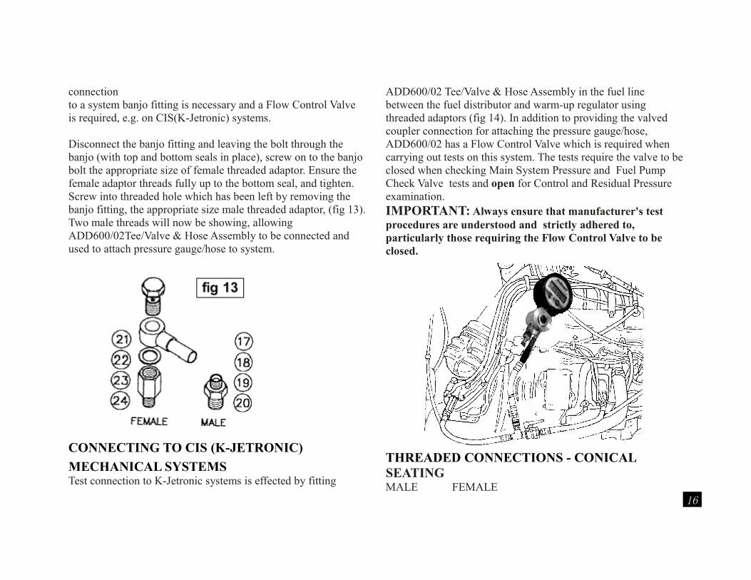
connection to a system banjo fitting is necessary and a Flow Control Valve is required, e.g. on CIS(K-Jetronic) systems.
Disconnect the banjo fitting and leaving the bolt through the banjo (with top and bottom seals in place), screw on to the banjo bolt the appropriate size of female threaded adaptor. Ensure the female adaptor threads fully up to the bottom seal, and tighten. Screw into threaded hole which has been left by removing the banjo fitting, the appropriate size male threaded adaptor, (fig 13). Two male threads will now be showing, allowing ADD600/02Tee/Valve & Hose Assembly to be connected and used to attach pressure gauge/hose to system.
CONNECTING TO CIS (K-JETRONIC)
MECHANICAL SYSTEMSTest connection to K-Jetronic systems is effected by fitting
ADD600/02 Tee/Valve & Hose Assembly in the fuel line between the fuel distributor and warm-up regulator using threaded adaptors (fig 14). In addition to providing the valved coupler connection for attaching the pressure gauge/hose,ADD600/02 has a Flow Control Valve which is required when carrying out tests on this system. The tests require the valve to be closed when checking Main System Pressure and Fuel Pump Check Valve tests and open for Control and Residual Pressure examination. IMPORTANT: Always ensure that manufacturer's test procedures are understood and strictly adhered to, particularly those requiring the Flow Control Valve to be closed.
THREADED CONNECTIONS - CONICAL SEATINGMALE FEMALE
16
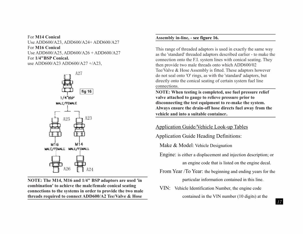
For M14 Conical Use ADD600/A23, ADD600/A24+ ADD600/A27For M16 Conical Use ADD600/A25, ADD600/A26 + ADD600/A27For 1/4"BSP Conical. use ADD600/A23 ADD600/A27 +/A23,
NOTE: The M14, M16 and 1/4" BSP adaptors are used 'in combination' to achieve the male/female conical seating connections to the systems in order to provide the two male threads required to connect ADD600/A2 Tee/Valve & Hose
Assembly in-line, - see figure 16.
This range of threaded adaptors is used in exactly the same way as the 'standard' threaded adaptors described earlier - to make the connection onto the F.I. system lines with conical seating. They then provide two male threads onto which ADD600/02 Tee/Valve & Hose Assembly is fitted. These adaptors however do not seal onto 'O' rings, as with the 'standard' adaptors, but directly onto the conical seating of certain system fuel line connections.NOTE: When testing is completed, use fuel pressure relief valve attached to gauge to relieve pressure prior to disconnecting the test equipment to re-make the system. Always ensure the drain-off hose directs fuel away from the vehicle and into a suitable container.
Application Guide/Vehicle Look-up Tables
Application Guide Heading Definitions:
Make & Model: Vehicle Designation
Engine: is either a displacement and injection description; or
an engine code that is listed on the engine decal.
From Year /To Year: the beginning and ending years for the
particular information contained in this line.
VIN: Vehicle Identification Number, the engine code
contained in the VIN number (10 digits) at the 17
base of the windshield. Imports do not use this
code in this chart .
KOEO: stands for “key on; engine off”
Normal Idle: engine at normal operating temperature, low
idle speed
Idle w/o Vacuum: applies to port injected vehicles. This is
the pressure of the system with the vacuum
removed from the fuel pressure regulator.
Deadhead: the system pressure with the return line blocked off.
CAUTION NOTE: Do not pinch plastic or braided steel lines.
Adapter Kit: indicates in which kit the listed adapter is
available.
Fitting Location: where the adapter is installed on the vehicle.
Manual Pump Energize: how to activate the fuel pump
without the engine running.
RPO: Regular Production Option; the production code
contained in the vehicle option label.
European Fuel Pressure CIS Tables:
System Pressure: pressure reading while vehicle is being
operated (driven).
Control /Differential@68℉: Pressure reading at room
temperature once vehicle has been shut down and
allowed to surpass rest pressure (while stored
indoors).
Rest pressure: pressure reading reached once vehicle has
been turned off and reached rest time .
Rest Time: amount of time required to reach rest pressure.
Using the Application Guide Look-up Tables:
The following are general guidelines for using the
enclosed Vehicle Look-up Tables
1.) Locate the vehicle in question in the look-up table headings
by utilizing one or all of the following :
- Make & Model of vehicle
- Engine
- From Year / to Year
2.) Once the vehicle has been identified, the proper adapter(s),
as well as the fitting location will need to be determined.
This information is found under the columns entitled Adapter
Fitting and Fitting Location. Following the line for the
18
specific vehicle over to the these columns to find the
information needed. The Adapter Fitting column lists the
actual fitting needed. The number listed corresponds to the
number stamped on the adapter in the kit. The Fitting
Location column will tell the technician where in the vehicle
to attach the designated adapter. Because of space limitations
and the desire to give as much information as possible to the
user, the Fitting Location column users a footnote method to
provide all the required information. The technician needs to
reference the number footnote given in this column. The
number (found in parenthesis within the column) is
referenced in the ‘Key to Look-up Table Footnotes’ found
beginning on page 00,and provides an explanation as to
where the fuel connection can be located for that specific
vehicle.
NOTE: This same method of identifying information is used with the KOEO, Normal Idle and Manual Pump Energize columns.
3.) After choosing the adapter and referencing the Fitting
Location, the additional columns of KOEO, Normal Idle w/o
Vacuum and Deadhead pressure will provide the technician
with additional pertinent information. Listed in these
columns are the actual pressure or pressure range which can
be read from the Digital Remote Fuel Pressure Gauge for the
vehicle being tested.
NOTE: KOEO indicates (for those vehicles listing a reading and/ or a footnote) that a fuel pressure reading can be made with the key on without the engine running.
4.) The European Fuel Pressure CIS tables (found on pg37-39)
list those vehicles with CIS fuel pressure systems. Use these
tables the same way described above. The difference in these
tables is in the way the information is given; ie. There are 4
columns which list the fuel pressure readings in both bar&
psi Measurement which replace the columns VIN thru
19
Deadhead Pressure.
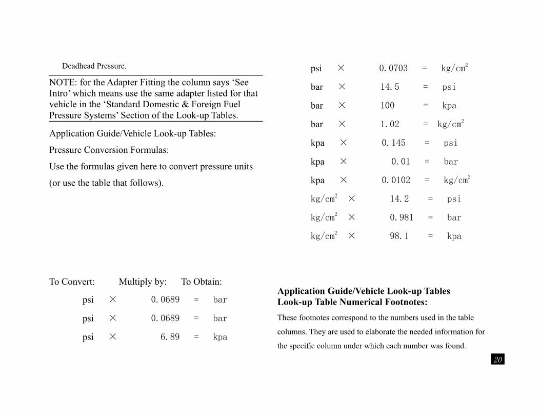
NOTE: for the Adapter Fitting the column says ‘See Intro’ which means use the same adapter listed for that vehicle in the ‘Standard Domestic & Foreign Fuel Pressure Systems’ Section of the Look-up Tables.
Application Guide/Vehicle Look-up Tables:
Pressure Conversion Formulas:
Use the formulas given here to convert pressure units
(or use the table that follows).
To Convert: Multiply by: To Obtain:
psi × 0.0689 = bar
psi × 0.0689 = bar
psi × 6.89 = kpa
psi × 0.0703 = kg/cm2
bar × 14.5 = psi
bar × 100 = kpa
bar × 1.02 = kg/cm2
kpa × 0.145 = psi
kpa × 0.01 = bar
kpa × 0.0102 = kg/cm2
kg/cm2 × 14.2 = psi
kg/cm2 × 0.981 = bar
kg/cm2 × 98.1 = kpa
Application Guide/Vehicle Look-up TablesLook-up Table Numerical Footnotes:
These footnotes correspond to the numbers used in the table
columns. They are used to elaborate the needed information for
the specific column under which each number was found.
20
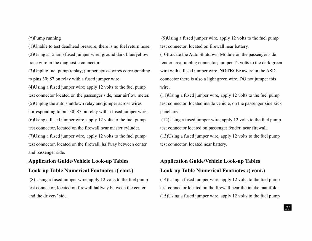
(*)Pump running
(1)Unable to test deadhead pressure; there is no fuel return hose.
(2)Using a 15 amp fused jumper wire; ground dark blue/yellow
trace wire in the diagnostic connector.
(3)Unplug fuel pump replay; jumper across wires corresponding
to pins 30; 87 on relay with a fused jumper wire.
(4)Using a fused jumper wire; apply 12 volts to the fuel pump
test connector located on the passenger side, near airflow meter.
(5)Unplug the auto shutdown relay and jumper across wires
corresponding to pins30; 87 on relay with a fused jumper wire.
(6)Using a fused jumper wire, apply 12 volts to the fuel pump
test connector, located on the firewall near master cylinder.
(7)Using a fused jumper wire, apply 12 volts to the fuel pump
test connector, located on the firewall, halfway between center
and passenger side.
Application Guide/Vehicle Look-up Tables
Look-up Table Numerical Footnotes :( cont.)
(8) Using a fused jumper wire, apply 12 volts to the fuel pump
test connector, located on firewall halfway between the center
and the drivers’ side.
(9)Using a fused jumper wire, apply 12 volts to the fuel pump
test connector, located on firewall near battery.
(10)Locate the Auto Shutdown Module on the passenger side
fender area; unplug connector; jumper 12 volts to the dark green
wire with a fused jumper wire. NOTE: Be aware in the ASD
connector there is also a light green wire. DO not jumper this
wire.
(11)Using a fused jumper wire, apply 12 volts to the fuel pump
test connector, located inside vehicle, on the passenger side kick
panel area.
(12)Using a fused jumper wire, apply 12 volts to the fuel pump
test connector located on passenger fender, near firewall.
(13)Using a fused jumper wire, apply 12 volts to the fuel pump
test connector, located near battery.
Application Guide/Vehicle Look-up Tables
Look-up Table Numerical Footnotes :( cont.)
(14)Using a fused jumper wire, apply 12 volts to the fuel pump
test connector located on the firewall near the intake manifold.
(15)Using a fused jumper wire, apply 12 volts to the fuel pump
21
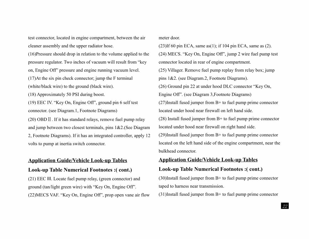
test connector, located in engine compartment, between the air
cleaner assembly and the upper radiator hose.
(16)Pressure should drop in relation to the volume applied to the
pressure regulator. Two inches of vacuum will result from “key
on, Engine Off” pressure and engine running vacuum level.
(17)At the six pin check connector; jump the F terminal
(white/black wire) to the ground (black wire).
(18) Approximately 50 PSI during boost.
(19) EEC IV. “Key On, Engine Off”, ground pin 6 self test
connector. (see Diagram.1, Footnote Diagrams)
(20) OBDⅡ. If it has standard relays, remove fuel pump relay
and jump between two closest terminals, pins 1&2.(See Diagram
2, Footnote Diagrams). If it has an integrated controller, apply 12
volts to pump at inertia switch connector.
Application Guide/Vehicle Look-up Tables
Look-up Table Numerical Footnotes :( cont.)
(21) EEC . Locate fuel pump relay, (green connector) andⅢ
ground (tan/light green wire) with “Key On, Engine Off”.
(22)MECS VAF. “Key On, Engine Off”, prop open vane air flow
meter door.
(23)If 60 pin ECA, same as(1); if 104 pin ECA, same as (2).
(24) MECS. “Key On, Engine Off”, jump 2 wire fuel pump test
connector located in rear of engine compartment.
(25) Villager. Remove fuel pump replay from relay box; jump
pins 1&2. (see Diagram.2, Footnote Diagrams).
(26) Ground pin 22 at under hood DLC connector “Key On,
Engine Off”. (see Diagram 3,Footnote Diagrams)
(27)Install fused jumper from B+ to fuel pump prime connector
located under hood near firewall on left hand side.
(28) Install fused jumper from B+ to fuel pump prime connector
located under hood near firewall on right hand side.
(29)Install fused jumper from B+ to fuel pump prime connector
located on the left hand side of the engine compartment, near the
bulkhead connector.
Application Guide/Vehicle Look-up Tables
Look-up Table Numerical Footnotes :( cont.)
(30)Install fused jumper from B+ to fuel pump prime connector
taped to harness near transmission.
(31)Install fused jumper from B+ to fuel pump prime connector
22
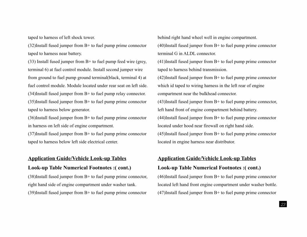
taped to harness of left shock tower.
(32)Install fused jumper from B+ to fuel pump prime connector
taped to harness near battery.
(33) Install fused jumper from B+ to fuel pump feed wire (grey,
terminal 6) at fuel control module. Install second jumper wire
from ground to fuel pump ground terminal(black, terminal 4) at
fuel control module. Module located under rear seat on left side.
(34)Install fused jumper from B+ to fuel pump relay connector.
(35)Install fused jumper from B+ to fuel pump prime connector
taped to harness below generator.
(36)Install fused jumper from B+ to fuel pump prime connector
in harness on left side of engine compartment.
(37)Install fused jumper from B+ to fuel pump prime connector
taped to harness below left side electrical center.
Application Guide/Vehicle Look-up Tables
Look-up Table Numerical Footnotes :( cont.)
(38)Install fused jumper from B+ to fuel pump prime connector,
right hand side of engine compartment under washer tank.
(39)Install fused jumper from B+ to fuel pump prime connector
behind right hand wheel well in engine compartment.
(40)Install fused jumper from B+ to fuel pump prime connector
terminal G in ALDL connector.
(41)Install fused jumper from B+ to fuel pump prime connector
taped to harness behind transmission.
(42)Install fused jumper from B+ to fuel pump prime connector
which id taped to wiring harness in the left rear of engine
compartment near the bulkhead connector.
(43)Install fused jumper from B+ to fuel pump prime connector,
left hand front of engine compartment behind battery.
(44)Install fused jumper from B+ to fuel pump prime connector
located under hood near firewall on right hand side.
(45)Install fused jumper from B+ to fuel pump prime connector
located in engine harness near distributor.
Application Guide/Vehicle Look-up Tables
Look-up Table Numerical Footnotes :( cont.)
(46)Install fused jumper from B+ to fuel pump prime connector
located left hand front engine compartment under washer bottle.
(47)Install fused jumper from B+ to fuel pump prime connector
23
near right hand wheel well in engine compartment.
(48)Install fused jumper from B+ to the data link connector,
terminal fp.
(49)Install fused jumper from B+ to fuel pump prime connector
near thermostat housing.
(50)Install fused jumper from B+ to fuel pump prime connector
located in front right hand corner of engine compartment.
(51) Ground ECU terminal 104 with key on.
(52) With a fused jumper, apply power to the black/red wire at
the fuel pump relay in the under hood relay box.
(53)Jump power to the R/L at the fuel pump relay under the
hood.
(54) Jump power to the R/G at the fuel pump relay under the
hood.
(55) Jump pins 1 (B /Y) and 3 (B/L) at the fuel pump relay.
Application Guide/Vehicle Look-up Tables
Look-up Table Numerical Footnotes :( cont.)
(56) Jump power to the fuel pump check connector (B/R) on the
left inner vender.
(57) Jump power to the fuel pump check connector (G/R) on
right inner fender.
(58) At data link connector F/P to ground, turn the key on.
(59)Jump 2 wire T-shaped connector by wiper motor. Wires are
G/W & B.
(60)At diagnosis connector, jump F/P to ground.
(61)Jump 2 wire check connector on center of firewall. Wires are
yellow/red or light green & black.
(62)Jump 2 wire yellow check connector on left side of firewall.
Wires are light green & black.
(63)Jump 2 wire yellow check connector by the air flow sensor.
Wires are black/red & black.
(64)Jump 2 wire yellow check connector behind the air flow
sensor. Wires are brown/yellow & black.
(65) Jump 2 yellow check connector behind the air flow sensor.
Wires are brown & black.
Application Guide/Vehicle Look-up Tables
Look-up Table Numerical Footnotes :( cont.)
(66)Jump 2 wire yellow connector by the fuel filter. Wires are
blue/green & black.
(67) With both hoses off, 45-55 with the lower hose on.
24
(68) Ground fuel pump at terminal 106 of the ECU.
(69) Ground ECU terminal 108 (to energize fuel pump relay)or
bypass fuel pump relay-jump black/white to white/black.
(70) Ground fuel pump at terminal 108 of the ECU or bypass
fuel pump relay.
(71) Bypass fuel pump relay #1-jump black/white to light green/
red.
(72) Ground ECU terminal 104(to energize fuel pump relay) or
bypass fuel pump relay-jump black/white to black/yellow.
(73) Ground ECU terminal 8(to energize fuel pump relay)or
bypass fuel pump relay-jump black/white to black/yellow.
(74) Bypass fuel pump relay-jump white/black to green.
(75)Jump power and ground to external fuel pump.
(76) Bypass fuel pump relay (jump white/black to orange)and
ground fuel pump at fuel pump control unit(white wire).
Application Guide/Vehicle Look-up Tables
Look-up Table Numerical Footnotes :( cont.)
(77) Ground fuel pump at ECU terminal 108 or at the fuel pump
relay.
(78) Ground fuel pump at ECU terminal 014 (to energize fuel
pump relay) or bypass fuel pump relay-jump blue/black to black/
red.
(79) Ground ECU terminal 8(to energize fuel pump relay) or
bypass fuel pump relay-jump blue/black to black/red.
(80) Ground ECU terminal 104(to energize fuel pump relay)or
bypass fuel pump relay-jump P/black to black/white.
(81) Ground ECU terminal 108 (to energize fuel pump relay)or
bypass fuel pump relay-jump black/ white to white / blue.
(82) Ground ECU terminal 104(to energize fuel pump relay)or
bypass fuel pump relay-jump black/white to white/blue.
(83) Bypass the fuel pump relay-jump blue to red/blue or ground
fuel pump relay at terminal 18 of the ECU.
(84) Ground fuel pump at ECU terminal 108 or bypass fuel
pump relay-jump orange to black.
Application Guide/Vehicle Look-up Tables
Look-up Table Numerical Footnotes :( cont.)
(85) Ground fuel pump at ECU terminal 104 or bypass fuel
pump relay-jump orange to black.
(86) Ground ECU terminal 11(to energize fuel pump relay)or
25
bypass fuel pump relay-jump black/white to black/yellow.
(86) Ground ECU terminal 11(to energize fuel pump relay)or
bypass fuel pump relay-jump black/white to black/yellow.
(87)Bypass fuel pump relay-jump black/white to black/yellow
and ground fuel pump at fuel pump control module.
(88) Ground ECU terminal 108(to energize fuel pump relay) or
bypass fuel pump relay-jump purple to purple/white.
(89) Ground ECU terminal 104(to energize fuel pump relay) or
bypass fuel pump relay-jump purple to purple/white.
(90) Bypass fuel pump relay-jump white/black to white/purple.
(91) Ground ECU terminal 104(to energize fuel pump relay) or
bypass fuel pump relay-jump black/red to light green/red.
(92) Ground ECU terminal 104(to energize fuel pump relay) or
bypass fuel pump relay-jump brown to black/red.
(93) Ground fuel pump at ECU.
Application Guide/Vehicle Look-up Tables
Look-up Table Numerical Footnotes :( cont.)
(94) Ground fuel pump at ECU terminal 108.
(95) Ground ECU terminal 104(to energize fuel pump relay) or
bypass fuel pump relay-jump black/white to black/yellow.
(96) Ground fuel pump at ECU terminal 0.
(97) Ground ECU terminal 108(to energize fuel pump relay) or
bypass fuel pump relay-jump white/green to white/blue.
(98) Between fuel filter & fuel pipe.
(99) Between fuel filter & injection body.
(100) On particular vehicles, do not perform fuel pressure check
while fuel pressure regulator system is operating (on hot restart);
otherwise the pressrue gauge might indicate incorrect readings.
Wait at least 5 minutes after hot restart to check this value.
(101) Connect diagnosis connectors and turn key on; the fuel
pump should cycle on & off.
(102) Connect green test mode connectors and turn the key on;
the pump should cycle on &off.
(103) At fuel pump relay, jump the black/white to the
purple/black. Turn on ignition switch.
Application Guide/Vehicle Look-up Tables
Look-up Table Numerical Footnotes :( cont.)
(104) At control relay, jump the black/white to the purple/black.
Turn on the ignition switch.
(105) At fuel pump relay, jump the black/blue to the purple. Turn
26
on ignition switch.
(106) With the key on, jumper terminal marked +B and FP in the
diagnosis box with a fused jumper wire.
(107) With the key on, jumper the 2 terminals together in the
round 2 cavity connector near the air flow meter with a fused
jumper wire.
(108) With the key on, jumper the 2 terminals together in the
round 2 cavity connector near the power steering reservoir with a
fused jumper wire.
(109) With the key on, jumper the 2 terminals together in the T-
shaped 2 cavity connector near the right front strur tower with a
fused jumper wire.
(110) With the key on, jumper the 2 terminals together in the T-
shaped 2 cavity connector near the air flow meter with a fused
jumper wire.
Application Guide/Vehicle Look-up Tables
Look-up Table Numerical Footnotes :( cont.)
(111) With the key on, jumper the 2 terminals together in the T-
shaped 2 cavity connector on the passenger side firewall with a
fused jumper wire.
(112) When checking fuel pressure on a CIS system, the gauge
should be hooked up in the following manner: Remove the fuel
line from the center top port of the fuel distributor (this is the
line that goes to the control pressure regulator). Placer the gauge
and valve assembly so that the valve is on the control pressure
regulator side. Connect the valve side of the gauge to the control
pressure regulator fuel line, then connect the gauge side to the
center top port of the fuel distributor. In this position, with the
gauge valve open, control pressure is measured and with the
valve closed system pressure is measured.
When checking fuel pressure on a CIS-E system, the gauge
should be hooked up in the following manner: Remove the fuel
line to the cold start injector. Place the gauge and valve assembly
so that the valve is on the fuel distributor side. Connect the valve
side of the gauge and valve assembly to the fuel distributor test
Application Guide/Vehicle Look-up Tables
Look-up Table Numerical Footnotes :( cont.)
port (8mm Banjo fitting). Connect the gauge side to the cold
start injector fuel line. In this position, with the gauge valve
open, different pressure is measured and with the valve closed,
27
system pressure is measured.
All pressure are listed in BAR=14.7 psi.
(113) To manually energize the fuel pump on the CIS or CIS-E
equipped cars, you must bridge the safety circuit on the fuel
pump relay. In most cases, applying 12 volts on pin 87 on the
harness side of the relay will energize the fuel pump. In most
cases the fuel pump relay is located in, or near, the main vehicle
fuse panel, or near the vehicle ECU. Consult appropriate service
manual for additional information.
(114) Crank engine, then turn key off. System should hold this
pressure for at least 20 minutes.
(115) Bridge terminal 36 & 39 of air flow meter plug.
(116) Crank or run engine.
(117) Jump pins 5 & 6 in diagnostic connector D1.
(118) Key on.
Application Guide/Vehicle Look-up Tables
Look-up Table Numerical Footnotes :( cont.)
(119) Using a fused jumper, apply power to black/purple wire at
fuel pump relay.
(120) Using a fused jumper, apply power to wire at terminal 87/2
of fuel injection relay.
(121) Using a fused jumper, apply power to fuse #1.
(122) Using a fused jumper, apply power to fuse #11.
(123) Using a fused jumper, apply power to fuse #18.
(124) Using a fused jumper, apply power to fuse #20.
(125) Using a fused jumper, apply power to fuse #23.
(126) Using a fused jumper, apply power to fuse #C4.
(127) Using a fused jumper, apply power to fuse #2 in the
auxiliary fuse panel.
(128) Using a fused jumper, apply power to fuse #34.
(129) Using a fused jumper, apply power to fuse #23.
(130) Using a fused jumper, apply power to the green/purple
wire at the combined relay.
(131) Using a fused jumper, apply power to the output terminal
of the fuel pump relay.
Application Guide/Vehicle Look-up Tables
Look-up Table Numerical Footnotes :( cont.)
(132) Using a fused jumper, apply power to terminal 52 of the
fuel pump relay socket.
(133) Using a fused jumper, apply power to terminal 87 of the
28
fuel pump relay socket.
(134) Using a fused jumper, apply power to the white/purple
wire at the fuel pump relay.
(135) Cycle ignition key.
(136) Fuel Filter.
(137) Fuel rail.
(138) Fuel inlet.
(139) Throttle body.
(140) Tee into pressure line.
(141) On fuel rail below EGR valve.
(142) On fuel rail below throttle body unit.
(143) Jumper pins 1 & 3 of the fuel pump relay.
(144) Jumper pins 3 & 4 of the fuel pump relay.
(145) Between filter & rail.
(146) At pressure regulator.
Application Guide/Vehicle Look-up Tables
Look-up Table Numerical Footnotes :( cont.)
(147) At main hose to throttle body unit.
(148) Cold start injector.
(149) At fuel filter outlet.
(150) At fuel rail inlet.
(151) Fuel inlet pipe.
(152) Fuel delivery pipe.
(153) At fuel rail loop.
(154) At fuel pipe & main hose.
(155) At fuel rail plug.
(156) Rear of intake manifold, left side.
(157) With a fused jumper, apply power to the blue/black wire at
the fuel pump relay, under the center of the instrument panel
next to the ECM.
(158) T-connection for pressure regulator.
(159) Do not exceed pressure listed. Slowly block return line
until pressure is reached, then release.
ADD-TECHHTTP://WWW.ADDTOOLS.NET E-mail:[email protected]: It is our policy to continually improve
29
products and as such we reserve the right to alter data, specifications and component parts without prior notice.IMPORTANT: No liability is accepted for incorrect use of this equipment. WARRANTY: Guarantee is 12 months from purchase date, proof of which will be required for any claim.
Notes:
30